8051 training kit user guide - bipom.com is distributed with several example programs that...
TRANSCRIPT
MicroTRAK 8051 Training & Project Kit
User’s Guide
Date: 19 September 2010
Document Revision: 1.06
E-mail: [email protected] Web: www.bipom.com
BiPOM Electronics
2
© 1998-2010 by BiPOM Electronics, Inc. All rights reserved. MicroTRAK User’s Guide. No part of this work may be reproduced in any manner without written permission of BiPOM Electronics. All trademarked names in this manual are the property of respective owners. WARRANTY: BiPOM Electronics warrants MicroTRAK for a period of 1 year. If the product becomes defective during this period, BiPOM Electronics will at its option, replace or repair the product. This warranty is voided if the product is subjected to physical abuse or operated outside stated electrical limits. BiPOM Electronics will not be responsible for damage to any external devices connected to the microcontroller system. BiPOM Electronics disclaims all warranties express or implied warranties of merchantability and fitness for a particular purpose. In no event shall BiPOM Electronics be liable for any indirect, special, incidental or consequential damages in connection with or arising from the use of this product. BiPOM’s liability is limited to the purchase price of this product.
3
TABLE OF CONTENTS INTRODUCTION 4 INSTALLATION 5 Installing the Hardware 5 Installing the Software 6 Configuring Communications 10
Downloading Programs 11 Opening Projects 14 Creating Projects 17 Simulation 20 Carrier Board 23 Overview 23 8051 I/O Module 24 Overview 24 MINI-MAX/51-C2 25 Overview 25 Board Layout 26 Functional Block Diagram 26 Peripherals 32 Schematics 34 TRAINING BOARD TB1 35
Overview 35 Specifications 35 Board Layout 36 Functional Blocks 37 Schematics 39
ADVANCED PROJECT IDEAS 40
4
INTRODUCTION The 8051 micro-controller, first introduced by Intel more than two decades ago, is one of the most popular micro-controllers in use today with applications ranging from industrial, medical, home automation to automotive.
The objective of the MicroTRAK is to give students, engineers, technicians, hobbyists and other users experience with micro-controllers by developing practical applications using C and 8051 Assembly language. The MicroTRAK Lab Book consists of several labs that vary from simple to complicated.
When used in a school environment, it is recommended that the labs accompany a micro-controller course during the semester. Depending on the duration of each lab during the week, each lab in the student manual can be covered during one or two lab weeks. Based on the remaining time during the semester, the instructor may have the students work on one or more advanced projects. Some advanced project ideas are listed in Advanced Project Ideas section of this manual.
This User’s Guide is intended for the instructor to get familiar with and setup the MicroTRAK for the upcoming labs. The MicroTRAK Lab Book should be given to each student group in the lab to perform various exercises during the semester.
MicroTRAK can also be used as a Project Kit for rapid prototype development and proof-of-concept. The LED’s and DIP switches on the 8051 I/O Module allow easy control and monitoring of port pins. Keypad, LCD, microcontroller board and peripheral boards are already mounted on the carrier board, resulting in a presentable, single-piece assembly for demonstration purposes. LCD and keypad also facilitate software debugging. MicroTRAK consists of: • MINI-MAX/51-C2 Micro-controller Board • Training Board ( TB-1 ), PROTO-1 Prototyping Board • LCD with backlight ( adjustable brightness) , matrix keypad • Carrier board with extra regulator, I/O Module • Demo version of Micro C Compiler/Linker/Assembler • Demo version of BASCOM51 BASIC Compiler • Full version of SDCC C Compiler • Micro-IDE Integrated Development Environment/Simulator/Debugger • Serial cable, Power Supply • Example Lab book and this User’s Guide The following external items are required for each Training Kit station: • Personal Computer (PC) with
• Minimum 256MB memory and 200 MB of available hard disk space. • One available COM (RS232 Serial) Port ( or a USB to COM converter ) • Windows 98/ME/NT/2000/XP/Vista/Windows 7(32-bit or 64-bit) or higher.
• (Optional ) Digital Voltmeter
5
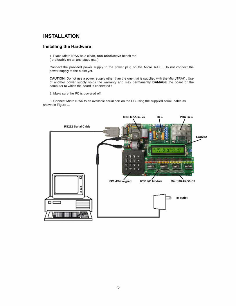
INSTALLATION Installing the Hardware 1. Place MicroTRAK on a clean, non-conductive bench top ( preferably on an anti-static mat )
Connect the provided power supply to the power plug on the MicroTRAK . Do not connect the power supply to the outlet yet.
CAUTION: Do not use a power supply other than the one that is supplied with the MicroTRAK . Use of another power supply voids the warranty and may permanently DAMAGE the board or the computer to which the board is connected !
2. Make sure the PC is powered off. 3. Connect MicroTRAK to an available serial port on the PC using the supplied serial cable as shown in Figure 1.
Figure 1
MINI-MAX/51-C2
RS232 Serial Cable
To outlet
TB-1 PROTO-1
KP1-4X4 keypad 8051 I/O Module MicroTRAK/51-С2
LCD242
6
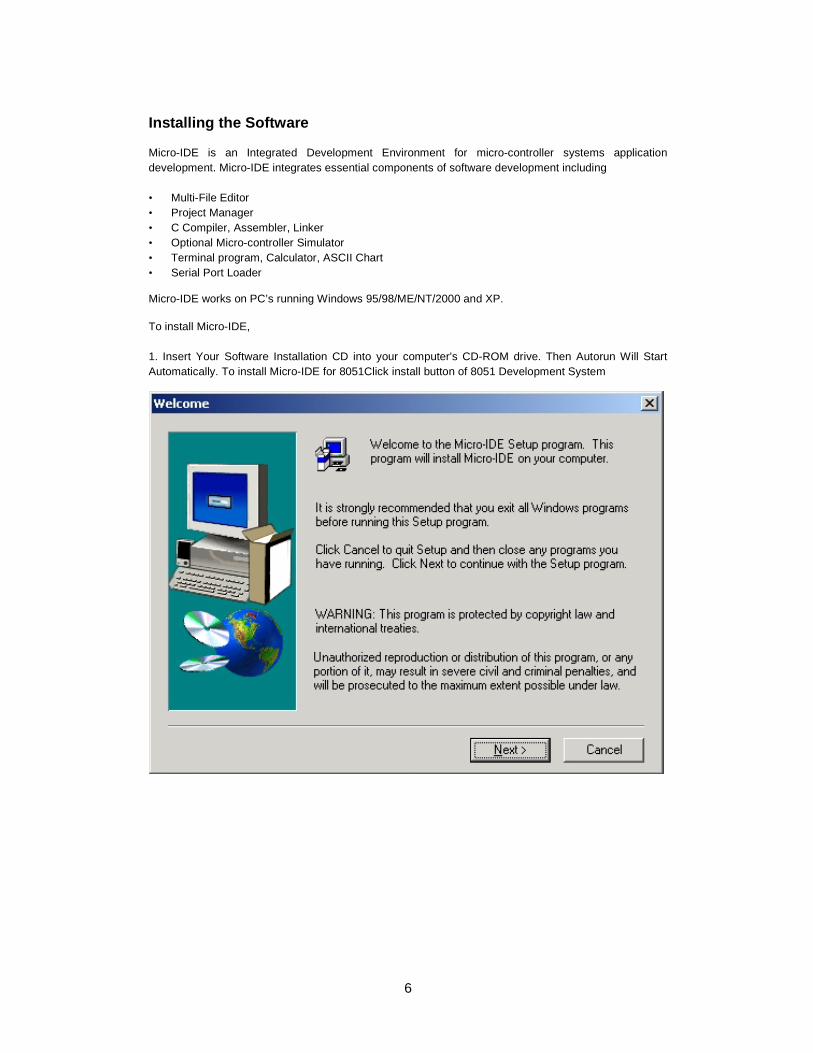
Installing the Software Micro-IDE is an Integrated Development Environment for micro-controller systems application development. Micro-IDE integrates essential components of software development including • Multi-File Editor • Project Manager • C Compiler, Assembler, Linker • Optional Micro-controller Simulator • Terminal program, Calculator, ASCII Chart • Serial Port Loader Micro-IDE works on PC’s running Windows 95/98/ME/NT/2000 and XP. To install Micro-IDE, 1. Insert Your Software Installation CD into your computer's CD-ROM drive. Then Autorun Will Start Automatically. To install Micro-IDE for 8051Click install button of 8051 Development System
7
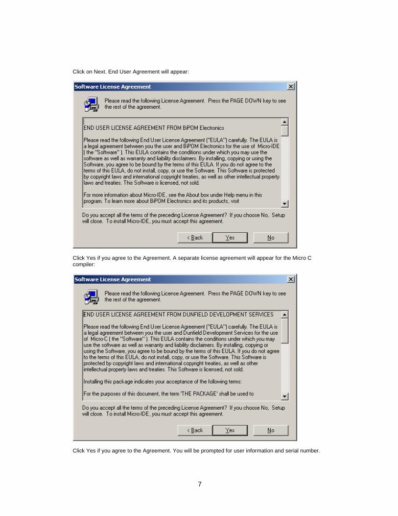
Click on Next. End User Agreement will appear:
Click Yes if you agree to the Agreement. A separate license agreement will appear for the Micro C compiler:
Click Yes if you agree to the Agreement. You will be prompted for user information and serial number.
8
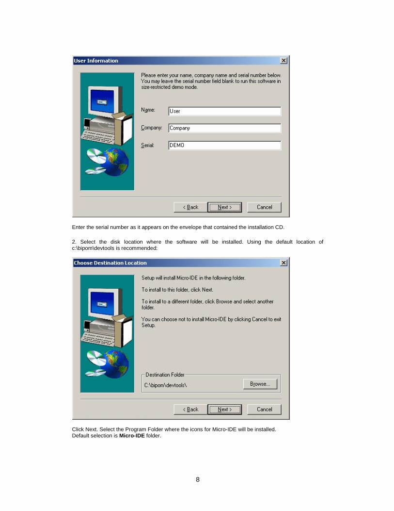
Enter the serial number as it appears on the envelope that contained the installation CD. 2. Select the disk location where the software will be installed. Using the default location of c:\bipom\devtools is recommended:
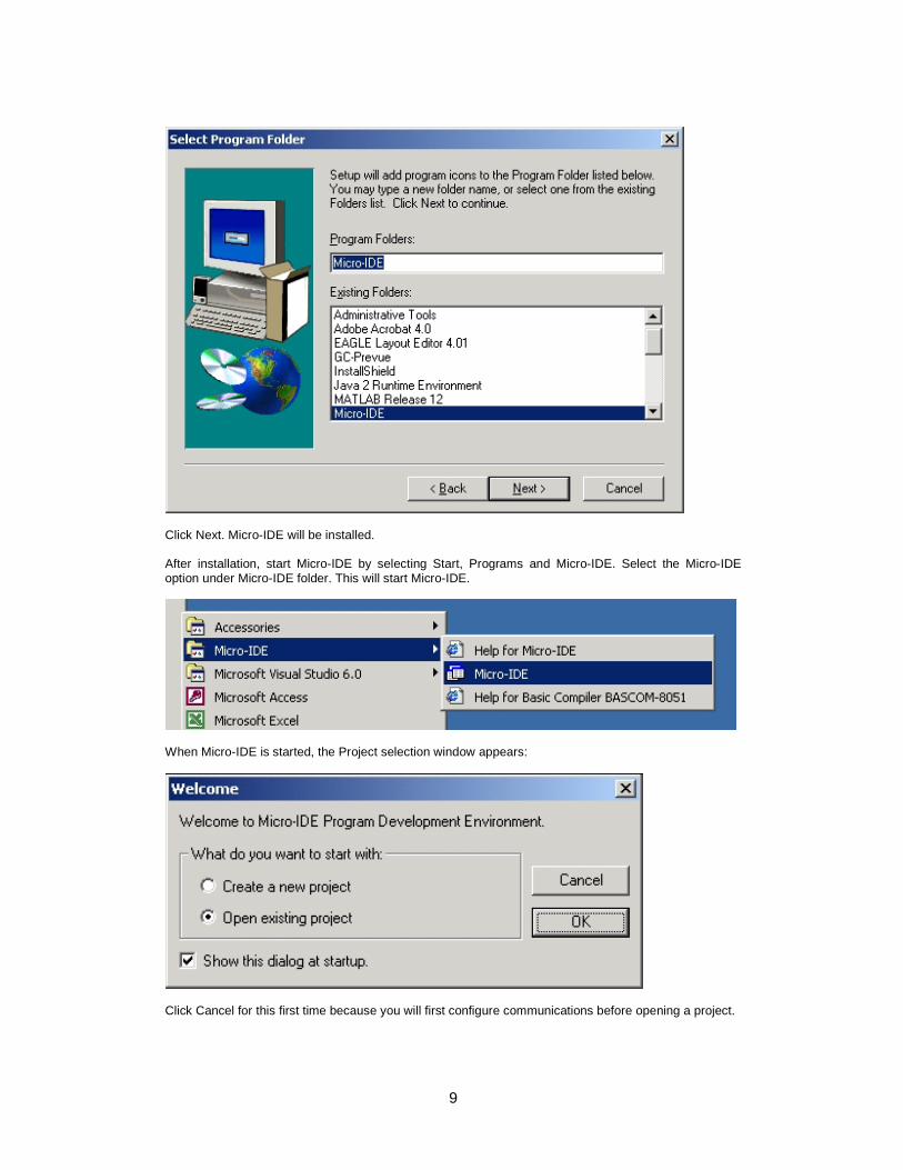
Click Next. Select the Program Folder where the icons for Micro-IDE will be installed. Default selection is Micro-IDE folder.
9
Click Next. Micro-IDE will be installed. After installation, start Micro-IDE by selecting Start, Programs and Micro-IDE. Select the Micro-IDE option under Micro-IDE folder. This will start Micro-IDE.
When Micro-IDE is started, the Project selection window appears:
Click Cancel for this first time because you will first configure communications before opening a project.

10
Configuring communications After you have started Micro-IDE, configure the correct COM port and communications parameters: 1. Select Tools and Options from the Micro-IDE menu. 2. Under Terminal tab, make sure Com Port is selected as the port that you connected to the MINI-MAX/51-C2 board. For example, if the board is connected to COM1, select COM1 under Terminal tab. Make sure that the Terminal options are set as follows:
Baud Rate: 19200 Data Bits: 8 Stop Bits: 1 Parity: None Echo: Off
3. Under Loader tab, make sure Com Port is selected as the port that you connected MINI-MAX/51-C2 board. For example, if the board is connected to COM1, select COM1 under Loader tab. Make sure that the Loader options are set as follows:
Baud Rate: 19200 Data Bits: 8 Stop Bits: 1 Parity: None Echo: Off
4. Open the Terminal window by selecting Terminal under View menu. A blank terminal screen will appear on the right side of the Micro-IDE window. ( You can resize the terminal screen by selecting the left edge of the terminal window with the left mouse button and dragging to the right. ). 5. Check communications to the MicroTRAK. Start the Terminal program by selecting Terminal under View menu. A blank terminal screen will appear on the right side of the Micro-IDE window. ( You can resize the terminal screen by selecting the left edge of the terminal window with the left mouse button and dragging to the right. ) 6. Select Tools, Terminal and Connect. This will connect the terminal to the 8051 Training Board.
11
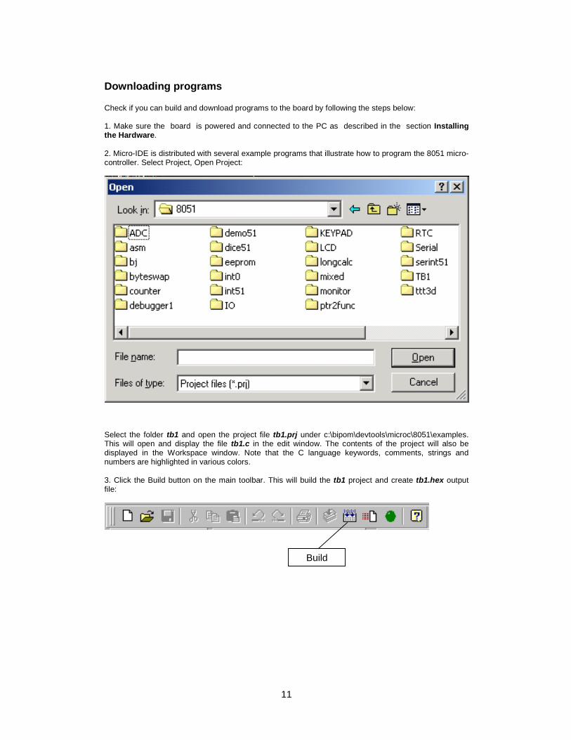
Downloading programs Check if you can build and download programs to the board by following the steps below: 1. Make sure the board is powered and connected to the PC as described in the section Installing the Hardware. 2. Micro-IDE is distributed with several example programs that illustrate how to program the 8051 micro-controller. Select Project, Open Project:
Select the folder tb1 and open the project file tb1.prj under c:\bipom\devtools\microc\8051\examples. This will open and display the file tb1.c in the edit window. The contents of the project will also be displayed in the Workspace window. Note that the C language keywords, comments, strings and numbers are highlighted in various colors. 3. Click the Build button on the main toolbar. This will build the tb1 project and create tb1.hex output file:
Build
12
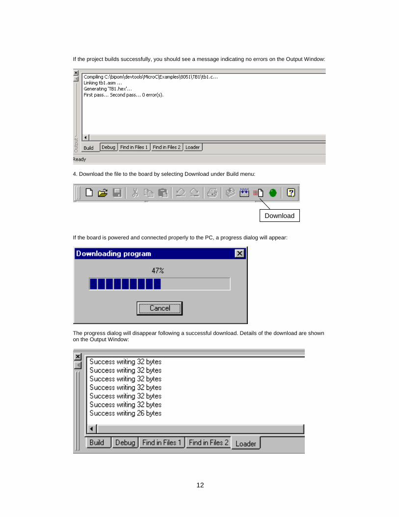
If the project builds successfully, you should see a message indicating no errors on the Output Window:
4. Download the file to the board by selecting Download under Build menu:
If the board is powered and connected properly to the PC, a progress dialog will appear:
The progress dialog will disappear following a successful download. Details of the download are shown on the Output Window:
Download
13
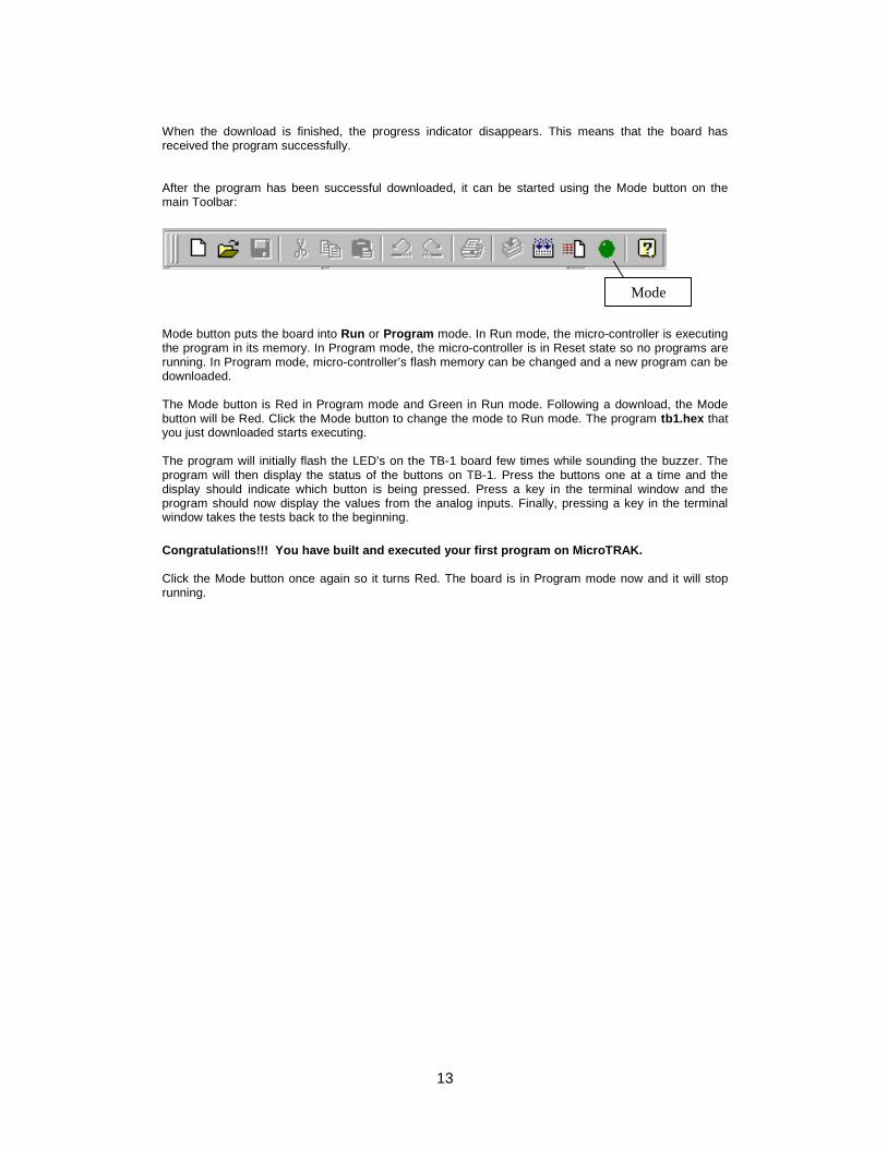
When the download is finished, the progress indicator disappears. This means that the board has received the program successfully. After the program has been successful downloaded, it can be started using the Mode button on the main Toolbar:
Mode button puts the board into Run or Program mode. In Run mode, the micro-controller is executing the program in its memory. In Program mode, the micro-controller is in Reset state so no programs are running. In Program mode, micro-controller’s flash memory can be changed and a new program can be downloaded. The Mode button is Red in Program mode and Green in Run mode. Following a download, the Mode button will be Red. Click the Mode button to change the mode to Run mode. The program tb1.hex that you just downloaded starts executing. The program will initially flash the LED’s on the TB-1 board few times while sounding the buzzer. The program will then display the status of the buttons on TB-1. Press the buttons one at a time and the display should indicate which button is being pressed. Press a key in the terminal window and the program should now display the values from the analog inputs. Finally, pressing a key in the terminal window takes the tests back to the beginning. Congratulations!!! You have built and executed your first program on MicroTRAK. Click the Mode button once again so it turns Red. The board is in Program mode now and it will stop running.
Mode
14
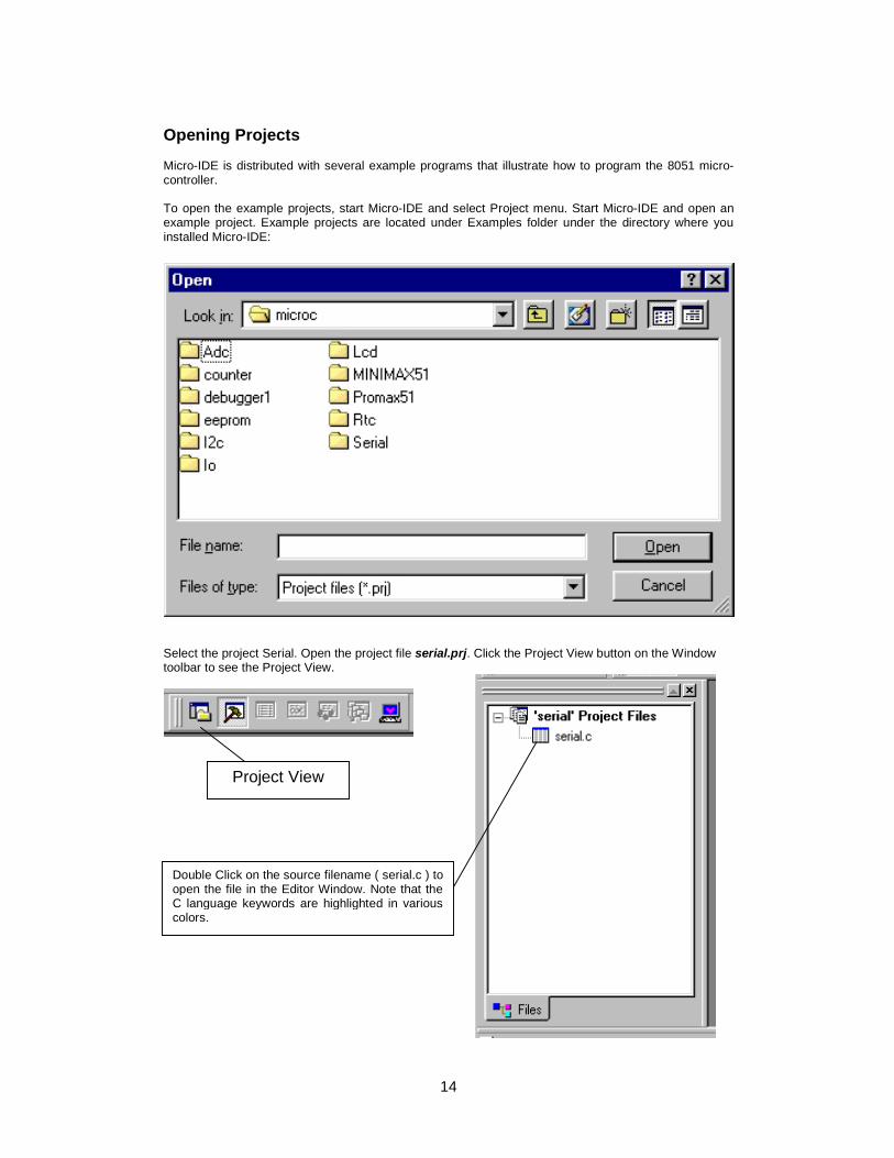
Opening Projects Micro-IDE is distributed with several example programs that illustrate how to program the 8051 micro-controller. To open the example projects, start Micro-IDE and select Project menu. Start Micro-IDE and open an example project. Example projects are located under Examples folder under the directory where you installed Micro-IDE:
Select the project Serial. Open the project file serial.prj. Click the Project View button on the Window toolbar to see the Project View.
Double Click on the source filename ( serial.c ) to open the file in the Editor Window. Note that the C language keywords are highlighted in various colors.
Project View
15
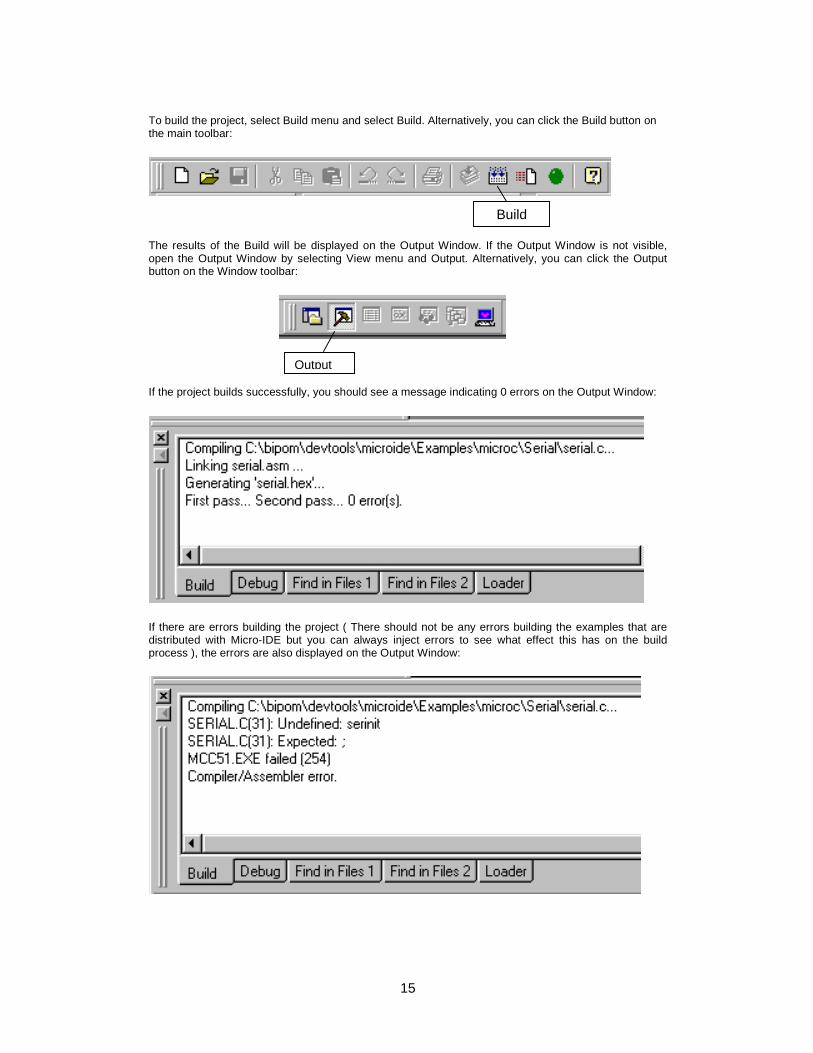
To build the project, select Build menu and select Build. Alternatively, you can click the Build button on the main toolbar:
The results of the Build will be displayed on the Output Window. If the Output Window is not visible, open the Output Window by selecting View menu and Output. Alternatively, you can click the Output button on the Window toolbar: If the project builds successfully, you should see a message indicating 0 errors on the Output Window:
If there are errors building the project ( There should not be any errors building the examples that are distributed with Micro-IDE but you can always inject errors to see what effect this has on the build process ), the errors are also displayed on the Output Window:
Build
Output

16
You can double click on the line that shows the error to immediately jump to the source line that contains the error. For example, if you click on the line SERIAL.C(31): Expected: ; your cursor will be positioned on line 31 in SERIAL.C
17
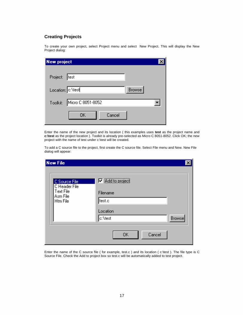
Creating Projects To create your own project, select Project menu and select New Project. This will display the New Project dialog:
Enter the name of the new project and its location ( this examples uses test as the project name and c:\test as the project location ). Toolkit is already pre-selected as Micro C 8051-8052. Click OK; the new project with the name of test under c:\test will be created. To add a C source file to the project, first create the C source file. Select File menu and New. New File dialog will appear:
Enter the name of the C source file ( for example, test.c ) and its location ( c:\test ). The file type is C Source File. Check the Add to project box so test.c will be automatically added to test project.
18
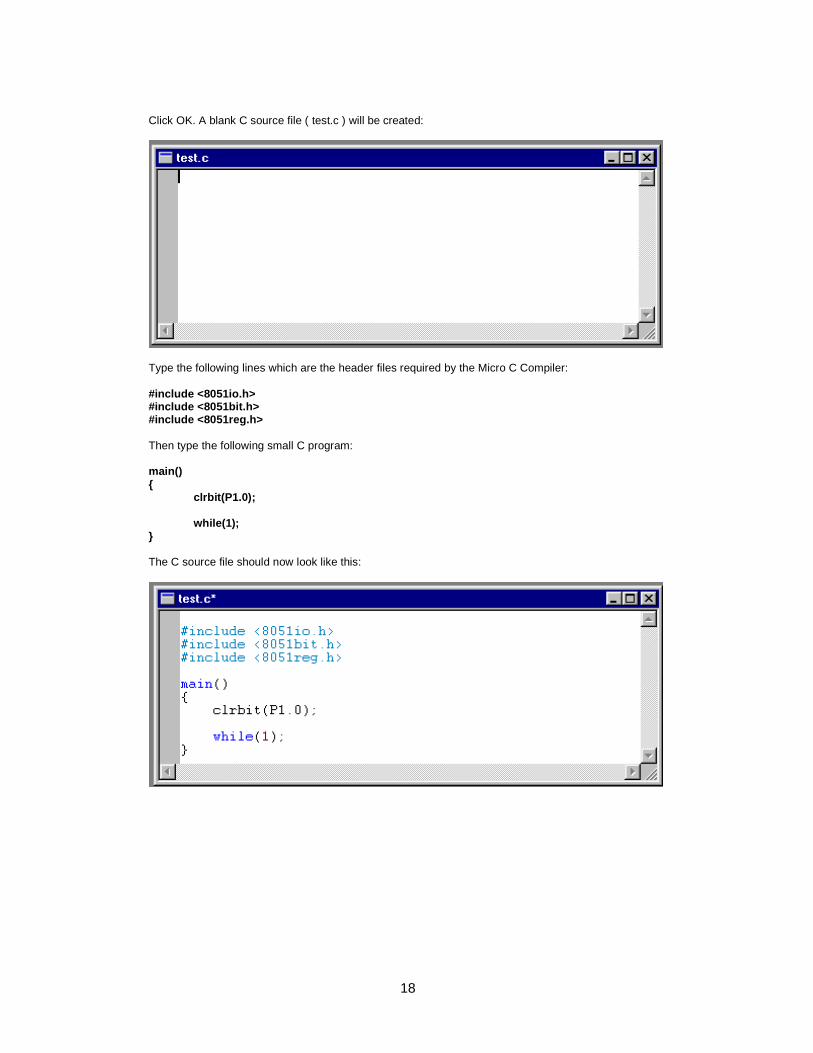
Click OK. A blank C source file ( test.c ) will be created:
Type the following lines which are the header files required by the Micro C Compiler: #include <8051io.h> #include <8051bit.h> #include <8051reg.h> Then type the following small C program: main() { clrbit(P1.0); while(1); } The C source file should now look like this:
19
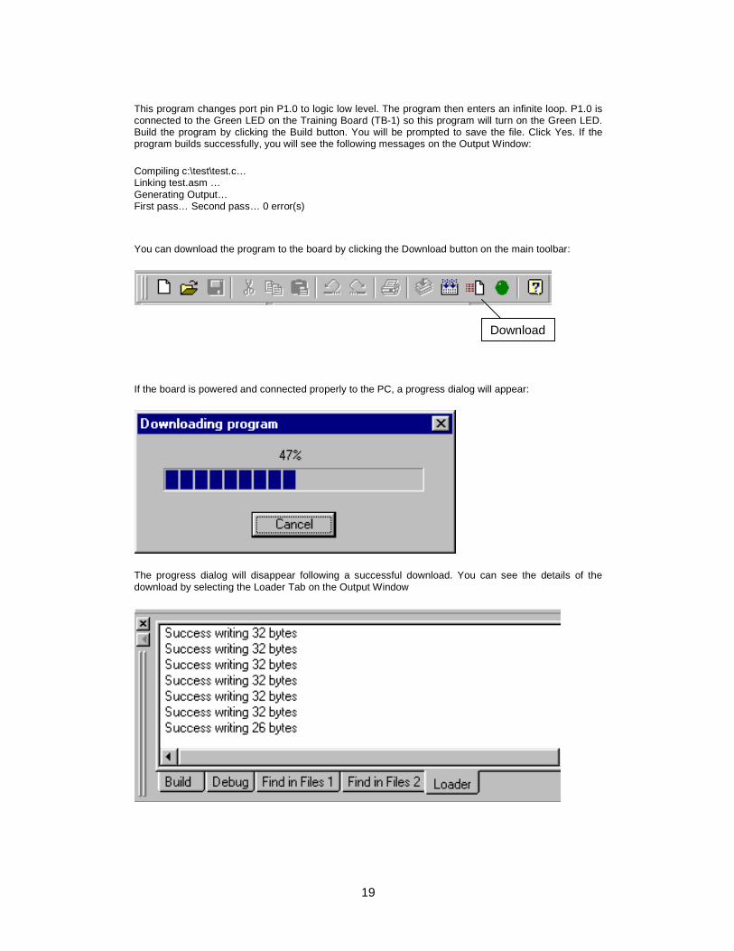
This program changes port pin P1.0 to logic low level. The program then enters an infinite loop. P1.0 is connected to the Green LED on the Training Board (TB-1) so this program will turn on the Green LED. Build the program by clicking the Build button. You will be prompted to save the file. Click Yes. If the program builds successfully, you will see the following messages on the Output Window: Compiling c:\test\test.c… Linking test.asm … Generating Output… First pass… Second pass… 0 error(s) You can download the program to the board by clicking the Download button on the main toolbar:
If the board is powered and connected properly to the PC, a progress dialog will appear:
The progress dialog will disappear following a successful download. You can see the details of the download by selecting the Loader Tab on the Output Window
Download
20
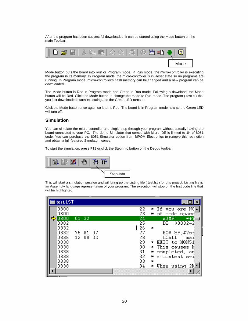
After the program has been successful downloaded, it can be started using the Mode button on the main Toolbar:
Mode button puts the board into Run or Program mode. In Run mode, the micro-controller is executing the program in its memory. In Program mode, the micro-controller is in Reset state so no programs are running. In Program mode, micro-controller’s flash memory can be changed and a new program can be downloaded. The Mode button is Red in Program mode and Green in Run mode. Following a download, the Mode button will be Red. Click the Mode button to change the mode to Run mode. The program ( test.c ) that you just downloaded starts executing and the Green LED turns on. Click the Mode button once again so it turns Red. The board is in Program mode now so the Green LED will turn off. Simulation You can simulate the micro-controller and single-step through your program without actually having the board connected to your PC. The demo Simulator that comes with Micro-IDE is limited to 1K of 8051 code. You can purchase the 8051 Simulator option from BiPOM Electronics to remove this restriction and obtain a full-featured Simulator license. To start the simulation, press F11 or click the Step Into button on the Debug toolbar:
This will start a simulation session and will bring up the Listing file ( test.lst ) for this project. Listing file is an Assembly language representation of your program. The execution will stop on the first code line that will be highlighted:
Step Into
Mode
21
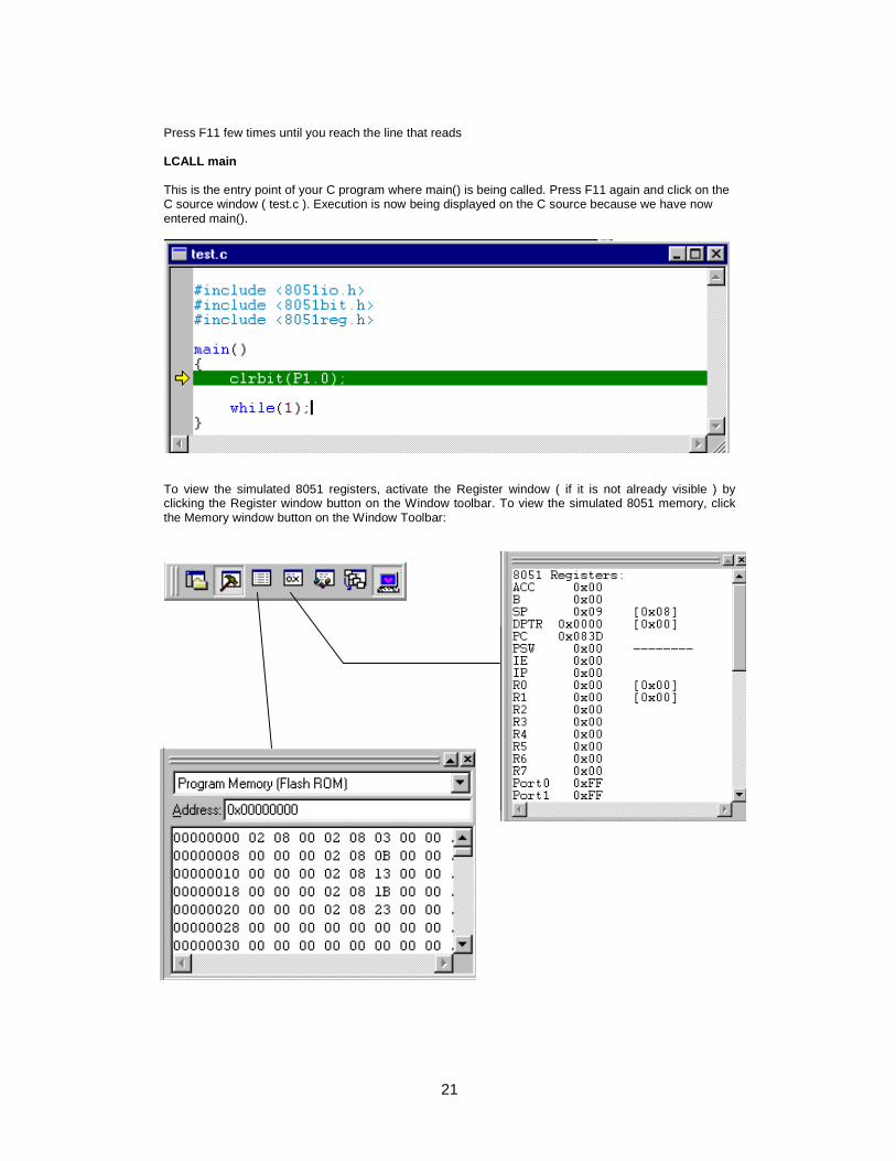
Press F11 few times until you reach the line that reads LCALL main This is the entry point of your C program where main() is being called. Press F11 again and click on the C source window ( test.c ). Execution is now being displayed on the C source because we have now entered main().
To view the simulated 8051 registers, activate the Register window ( if it is not already visible ) by clicking the Register window button on the Window toolbar. To view the simulated 8051 memory, click the Memory window button on the Window Toolbar:
22
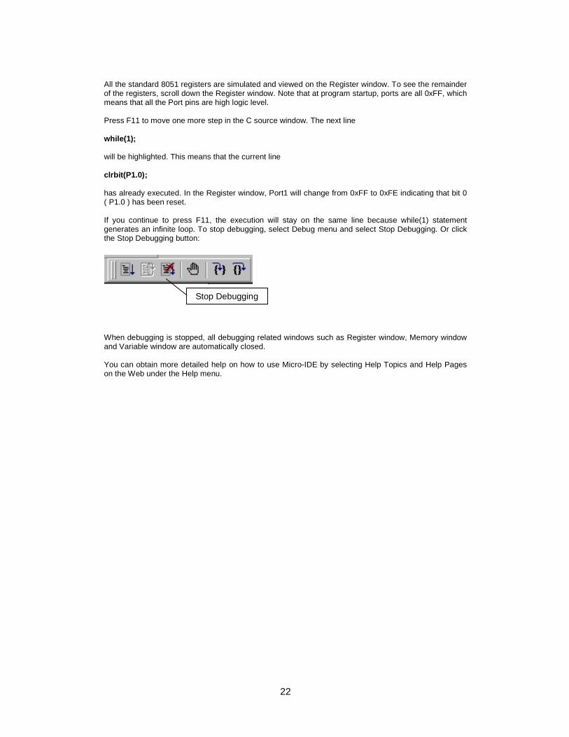
All the standard 8051 registers are simulated and viewed on the Register window. To see the remainder of the registers, scroll down the Register window. Note that at program startup, ports are all 0xFF, which means that all the Port pins are high logic level. Press F11 to move one more step in the C source window. The next line while(1); will be highlighted. This means that the current line clrbit(P1.0); has already executed. In the Register window, Port1 will change from 0xFF to 0xFE indicating that bit 0 ( P1.0 ) has been reset. If you continue to press F11, the execution will stay on the same line because while(1) statement generates an infinite loop. To stop debugging, select Debug menu and select Stop Debugging. Or click the Stop Debugging button:
When debugging is stopped, all debugging related windows such as Register window, Memory window and Variable window are automatically closed. You can obtain more detailed help on how to use Micro-IDE by selecting Help Topics and Help Pages on the Web under the Help menu.
Stop Debugging
23
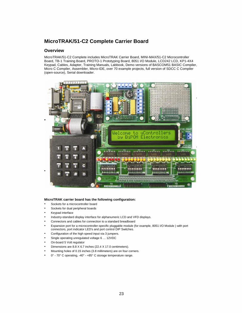
MicroTRAK/51-C2 Complete Carrier Board Overview
MicroTRAK/51-C2 Complete includes MicroTRAK Carrier Board, MINI-MAX/51-C2 Microcontroller Board, TB-1 Training Board, PROTO-1 Prototyping Board, 8051 I/O Module, LCD242 LCD, KP1-4X4 Keypad, Cables, Adapter, Training Manuals, Labbook, Demo versions of BASCOM51 BASIC Compiler, Micro C Compiler, Assembler, Micro-IDE, over 70 example projects, full version of SDCC C Compiler (open-source), Serial downloader.
MicroTRAK carrier board has the following configuration: • Sockets for a microcontroller board • Sockets for dual peripheral boards • Keypad interface • Industry-standard display interface for alphanumeric LCD and VFD displays. • Connectors and cables for connection to a standard breadboard • Expansion port for a microcontroller-specific pluggable module (for example, 8051 I/O Module ) with port
connectors, port indicator LED's and port control DIP Switches. • Configuration of the high speed input via 3 jumpers. • Single operating unregulated voltage 6 … 12VDC • On-board 5 Volt regulator • Dimensions are 8.8 X 6.7 inches (22.4 X 17.0 centimeters). • Mounting holes of 0.15 inches (3.8 millimeters) are on four corners. • 0° - 70° C operating, -40° - +85° C storage temperature range.
24
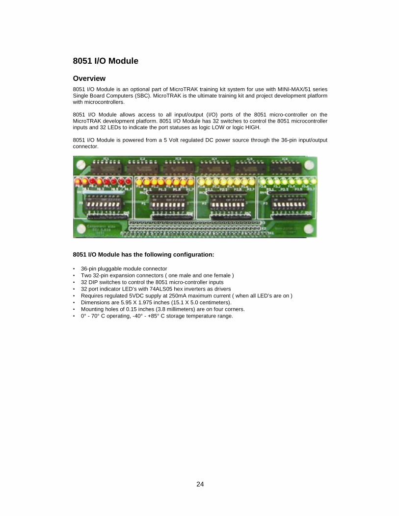
8051 I/O Module Overview
8051 I/O Module is an optional part of MicroTRAK training kit system for use with MINI-MAX/51 series Single Board Computers (SBC). MicroTRAK is the ultimate training kit and project development platform with microcontrollers. 8051 I/O Module allows access to all input/output (I/O) ports of the 8051 micro-controller on the MicroTRAK development platform. 8051 I/O Module has 32 switches to control the 8051 microcontroller inputs and 32 LEDs to indicate the port statuses as logic LOW or logic HIGH. 8051 I/O Module is powered from a 5 Volt regulated DC power source through the 36-pin input/output connector.
8051 I/O Module has the following configuration: • 36-pin pluggable module connector • Two 32-pin expansion connectors ( one male and one female ) • 32 DIP switches to control the 8051 micro-controller inputs • 32 port indicator LED’s with 74ALS05 hex inverters as drivers • Requires regulated 5VDC supply at 250mA maximum current ( when all LED’s are on ) • Dimensions are 5.95 X 1.975 inches (15.1 X 5.0 centimeters). • Mounting holes of 0.15 inches (3.8 millimeters) are on four corners. • 0° - 70° C operating, -40° - +85° C storage temperature range.
25
MINI-MAX/51-C2 Micro-controller Board Overview MINI-MAX/51-C2 is a general purpose, low-cost and highly-expandable micro-controller system. It is based on the ATMEL AT89C51ED2 single-chip Flash micro-controller. This micro-controller features • 64 Kilobytes of In-System Re-programmable Downloadable Flash Memory • 256 bytes of RAM • 1792 bytes of XRAM • 9-sources 4-level Interrupts • Programmable Counter Array with
- High Speed Output - Compare/Capture - Pulse Width Modulator
• Three 16 bit Timer/Counters • Programmable Enhanced UART Serial Channel • SPI Serial Interface • Programmable Watchdog Timer • 32 general purpose I/O pins MINI-MAX/51-C2 board complements these features by providing
• 512-byte Serial EEPROM ( optional 64-Kilobyte EEPROM ) • RS232 Serial Port • In-circuit Programming of the micro-controller through the serial port • 5-channel 10-bit ADC with 4.096V internal or an external voltage reference source • Keypad connector • LCD connector ( with programmable contrast adjustment for LCD ) • Expansion bus interface to low-cost peripheral boards such as
• Instrumentation amplifiers • Pressure inputs • Strain-gage inputs • 12 and 16-bit Analog-to-Digital Converters • Digital Input/Output cards • LED and LCD displays.
26
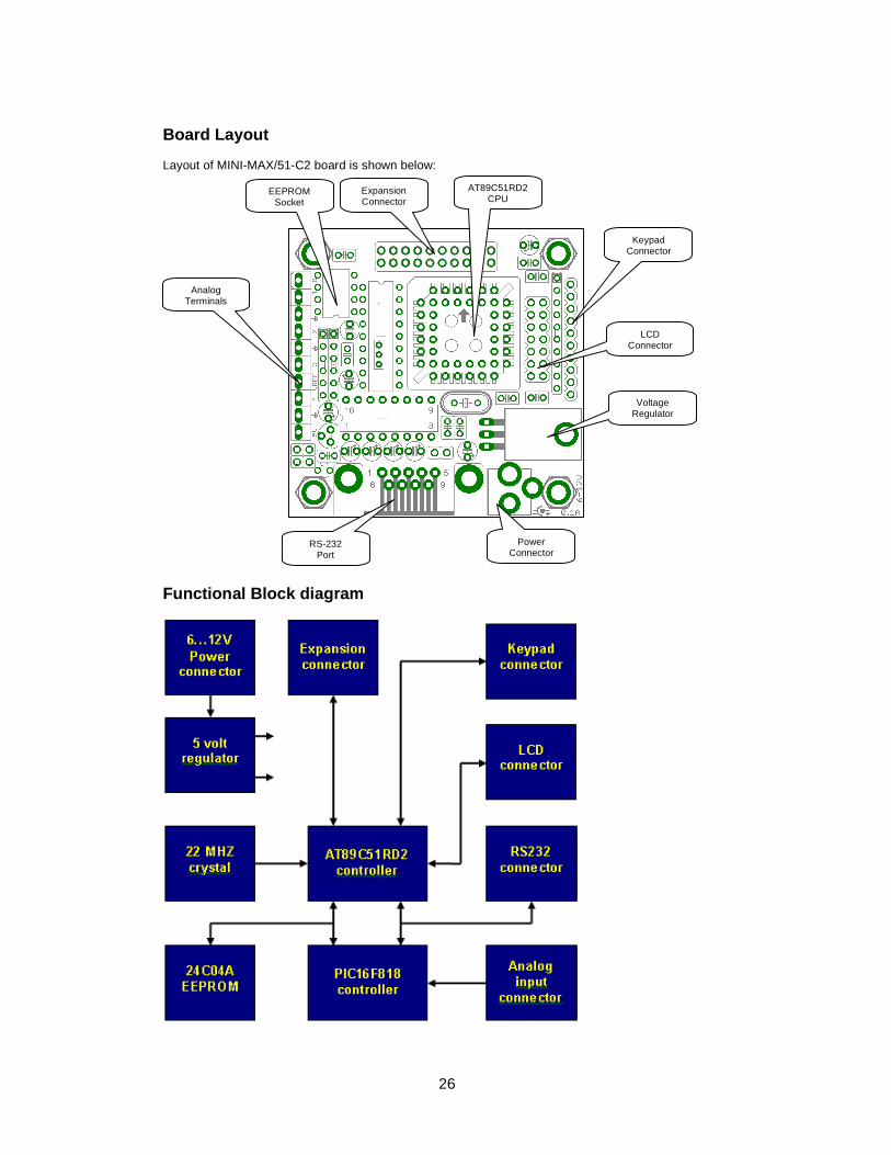
Board Layout Layout of MINI-MAX/51-C2 board is shown below: Functional Block diagram
EEPROM Socket
Expansion Connector
AT89C51RD2 CPU
Analog Terminals
RS-232 Port
Power Connector
Keypad Connector
LCD Connector
Voltage Regulator
27
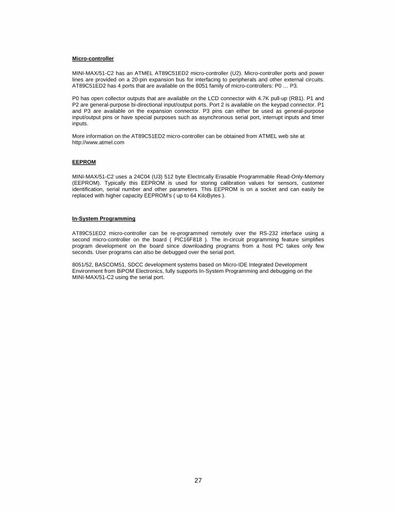
Micro-controller MINI-MAX/51-C2 has an ATMEL AT89C51ED2 micro-controller (U2). Micro-controller ports and power lines are provided on a 20-pin expansion bus for interfacing to peripherals and other external circuits. AT89C51ED2 has 4 ports that are available on the 8051 family of micro-controllers: P0 … P3. P0 has open collector outputs that are available on the LCD connector with 4.7K pull-up (RB1). P1 and P2 are general-purpose bi-directional input/output ports. Port 2 is available on the keypad connector. P1 and P3 are available on the expansion connector. P3 pins can either be used as general-purpose input/output pins or have special purposes such as asynchronous serial port, interrupt inputs and timer inputs. More information on the AT89C51ED2 micro-controller can be obtained from ATMEL web site at http://www.atmel.com
EEPROM MINI-MAX/51-C2 uses a 24C04 (U3) 512 byte Electrically Erasable Programmable Read-Only-Memory (EEPROM). Typically this EEPROM is used for storing calibration values for sensors, customer identification, serial number and other parameters. This EEPROM is on a socket and can easily be replaced with higher capacity EEPROM’s ( up to 64 KiloBytes ). In-System Programming AT89C51ED2 micro-controller can be re-programmed remotely over the RS-232 interface using a second micro-controller on the board ( PIC16F818 ). The in-circuit programming feature simplifies program development on the board since downloading programs from a host PC takes only few seconds. User programs can also be debugged over the serial port. 8051/52, BASCOM51, SDCC development systems based on Micro-IDE Integrated Development Environment from BiPOM Electronics, fully supports In-System Programming and debugging on the MINI-MAX/51-C2 using the serial port.
28
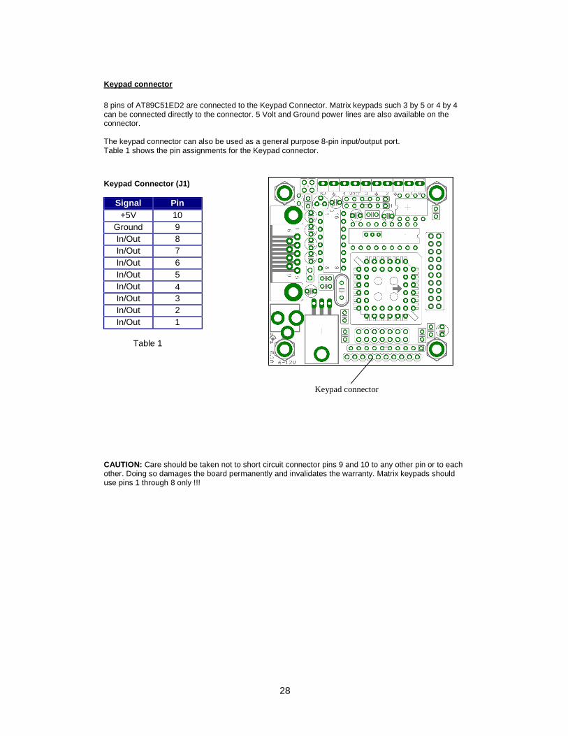
Keypad connector 8 pins of AT89C51ED2 are connected to the Keypad Connector. Matrix keypads such 3 by 5 or 4 by 4 can be connected directly to the connector. 5 Volt and Ground power lines are also available on the connector. The keypad connector can also be used as a general purpose 8-pin input/output port. Table 1 shows the pin assignments for the Keypad connector. Keypad Connector (J1)
Signal Pin +5V 10
Ground 9 In/Out 8 In/Out 7 In/Out 6 In/Out 5 In/Out 4 In/Out 3 In/Out 2 In/Out 1
Table 1
CAUTION: Care should be taken not to short circuit connector pins 9 and 10 to any other pin or to each other. Doing so damages the board permanently and invalidates the warranty. Matrix keypads should use pins 1 through 8 only !!!
Keypad connector
29
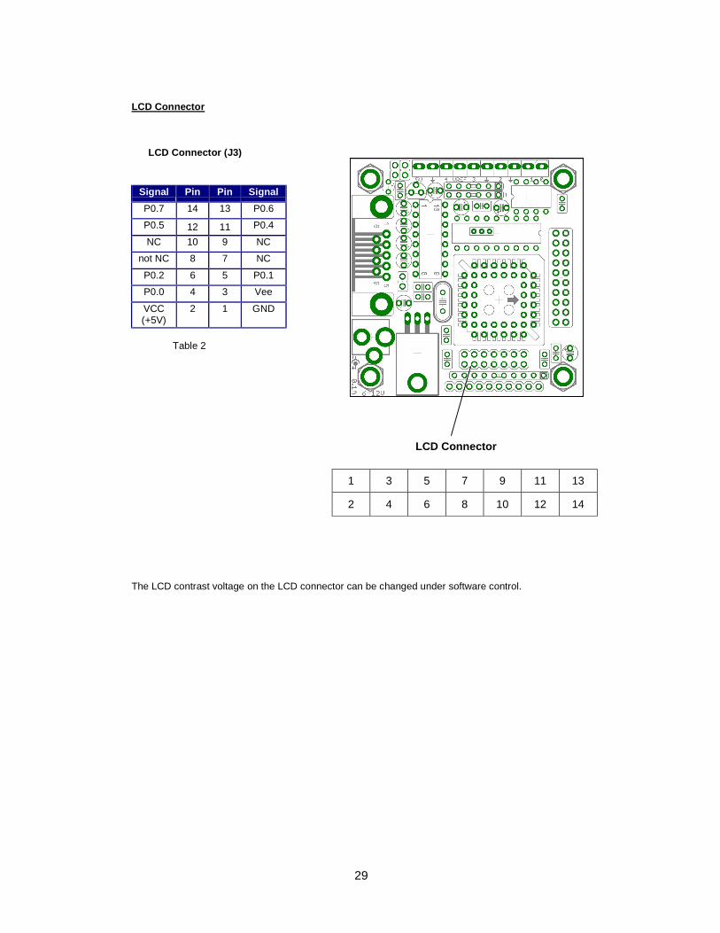
LCD Connector LCD Connector (J3)
Signal Pin Pin Signal P0.7 14 13 P0.6 P0.5 12 11 P0.4 NC 10 9 NC
not NC 8 7 NC P0.2 6 5 P0.1 P0.0 4 3 Vee VCC (+5V)
2 1 GND
Table 2
The LCD contrast voltage on the LCD connector can be changed under software control.
1 3 5 7 9 11 13
2 4 6 8 10 12 14
LCD Connector
30
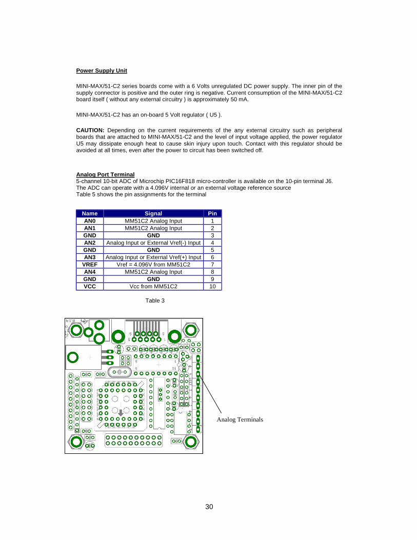
Power Supply Unit MINI-MAX/51-C2 series boards come with a 6 Volts unregulated DC power supply. The inner pin of the supply connector is positive and the outer ring is negative. Current consumption of the MINI-MAX/51-C2 board itself ( without any external circuitry ) is approximately 50 mA. MINI-MAX/51-C2 has an on-board 5 Volt regulator ( U5 ). CAUTION: Depending on the current requirements of the any external circuitry such as peripheral boards that are attached to MINI-MAX/51-C2 and the level of input voltage applied, the power regulator U5 may dissipate enough heat to cause skin injury upon touch. Contact with this regulator should be avoided at all times, even after the power to circuit has been switched off. Analog Port Terminal 5-channel 10-bit ADC of Microchip PIC16F818 micro-controller is available on the 10-pin terminal J6. The ADC can operate with a 4.096V internal or an external voltage reference source Table 5 shows the pin assignments for the terminal
Name Signal Pin AN0 MM51C2 Analog Input 1 AN1 MM51C2 Analog Input 2 GND GND 3 AN2 Analog Input or External Vref(-) Input 4 GND GND 5 AN3 Analog Input or External Vref(+) Input 6
VREF Vref = 4.096V from MM51C2 7 AN4 MM51C2 Analog Input 8 GND GND 9 VCC Vcc from MM51C2 10
Table 3
Analog Terminals
31
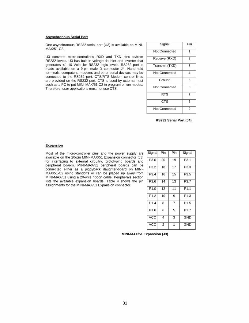
Asynchronous Serial Port One asynchronous RS232 serial port (U3) is available on MINI-MAX/51-C2. U3 converts micro-controller’s RXD and TXD pins to/from RS232 levels. U3 has built-in voltage-doubler and inverter that generates +/- 10 Volts for RS232 logic levels. RS232 port is made available on a 9-pin male D connector J4. Hand-held terminals, computers, modems and other serial devices may be connected to the RS232 port. CTS/RTS Modem control lines are provided on the RS232 port. CTS is used by external host such as a PC to put MINI-MAX/51-C2 in program or run modes. Therefore, user applications must not use CTS.
RS232 Serial Port (J4)
Expansion Most of the micro-controller pins and the power supply are available on the 20-pin MINI-MAX/51 Expansion connector (J3) for interfacing to external circuitry, prototyping boards and peripheral boards. MINI-MAX/51 peripheral boards can be connected either as a piggyback daughter-board on MINI-MAX/51-C2 using standoffs or can be placed up away from MINI-MAX/51 using a 20-wire ribbon cable. Peripherals section lists the available expansion boards. Table 4 shows the pin assignments for the MINI-MAX/51 Expansion connector.
MINI-MAX/51 Expansion (J3)
Signal Pin Not Connected 1 Receive (RXD) 2 Transmit (TXD) 3 Not Connected 4
Ground 5 Not Connected 6
RTS 7 CTS 8
Not Connected 9
Signal Pin Pin Signal P3.0 20 19 P3.1 P3.2 18 17 P3.3 P3.4 16 15 P3.5 P3.6 14 13 P3.7 P1.0 12 11 P1.1 P1.2 10 9 P1.3 P1.4 8 7 P1.5 P1.6 6 5 P1.7 VCC 4 3 GND VCC 2 1 GND
32
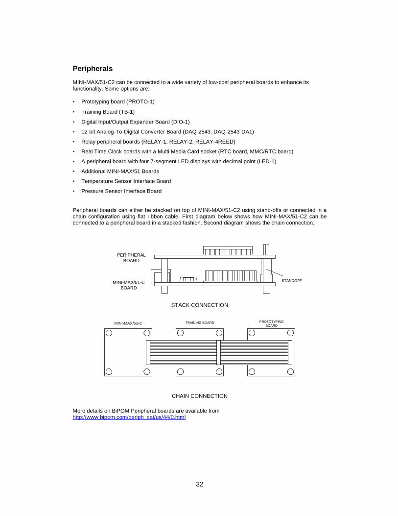
Peripherals MINI-MAX/51-C2 can be connected to a wide variety of low-cost peripheral boards to enhance its functionality. Some options are: • Prototyping board (PROTO-1)
• Training Board (TB-1)
• Digital Input/Output Expander Board (DIO-1)
• 12-bit Analog-To-Digital Converter Board (DAQ-2543, DAQ-2543-DA1)
• Relay peripheral boards (RELAY-1, RELAY-2, RELAY-4REED)
• Real Time Clock boards with a Multi Media Card socket (RTC board, MMC/RTC board)
• A peripheral board with four 7-segment LED displays with decimal point (LED-1)
• Additional MINI-MAX/51 Boards
• Temperature Sensor Interface Board
• Pressure Sensor Interface Board
Peripheral boards can either be stacked on top of MINI-MAX/51-C2 using stand-offs or connected in a chain configuration using flat ribbon cable. First diagram below shows how MINI-MAX/51-C2 can be connected to a peripheral board in a stacked fashion. Second diagram shows the chain connection.
STACK CONNECTION
CHAIN CONNECTION More details on BiPOM Peripheral boards are available from http://www.bipom.com/periph_cat/us/44/0.html
PERIPHERALBOARD
MINI-MAX/51-CBOARD
STANDOFF
MINI-MAX/51-C TRAINING BOARD PROTOTYPINGBOARD
33
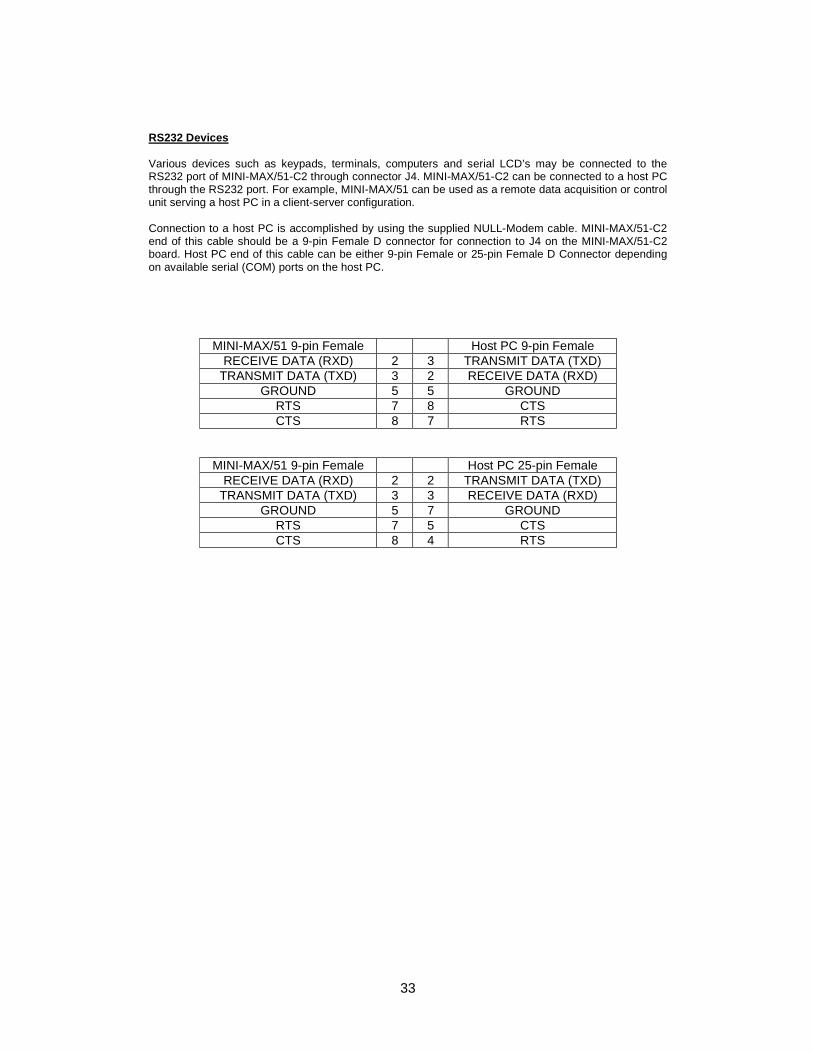
RS232 Devices Various devices such as keypads, terminals, computers and serial LCD’s may be connected to the RS232 port of MINI-MAX/51-C2 through connector J4. MINI-MAX/51-C2 can be connected to a host PC through the RS232 port. For example, MINI-MAX/51 can be used as a remote data acquisition or control unit serving a host PC in a client-server configuration. Connection to a host PC is accomplished by using the supplied NULL-Modem cable. MINI-MAX/51-C2 end of this cable should be a 9-pin Female D connector for connection to J4 on the MINI-MAX/51-C2 board. Host PC end of this cable can be either 9-pin Female or 25-pin Female D Connector depending on available serial (COM) ports on the host PC.
MINI-MAX/51 9-pin Female Host PC 9-pin Female RECEIVE DATA (RXD) 2 3 TRANSMIT DATA (TXD)
TRANSMIT DATA (TXD) 3 2 RECEIVE DATA (RXD) GROUND 5 5 GROUND
RTS 7 8 CTS CTS 8 7 RTS
MINI-MAX/51 9-pin Female Host PC 25-pin Female RECEIVE DATA (RXD) 2 2 TRANSMIT DATA (TXD)
TRANSMIT DATA (TXD) 3 3 RECEIVE DATA (RXD) GROUND 5 7 GROUND
RTS 7 5 CTS CTS 8 4 RTS
34
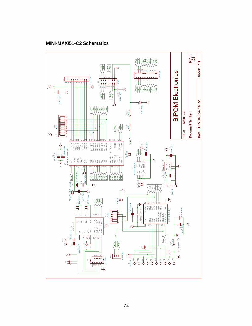
MINI-MAX/51-C2 Schematics

35
TB-1 TRAINING BOARD Overview Training Board TB-1 is an experimentation board that illustrates the many capabilities of the 8051 compatible micro-controllers. TB-1 features
- 3 Traffic light LED’s ( red, yellow, green ) - 2 interrupt inputs - 2 switch inputs ( in parallel with interrupt inputs ) - 2 timer/counter inputs - 4 channels of 8-bit analog inputs - Programmable buzzer - Expansion bus to other boards
TB-1 is already connected to the MINI-MAX/51-C2 board as part of the MicroTRAK. Specifications Dimensions are 2.35 X 2.40 inches ( 5.97 X 6.10 centimeters ). Mounting holes of 0.125 inches ( 3 millimeters ) on four corners. 0° - 70° C operating, -40° - +85° C storage temperature range
36
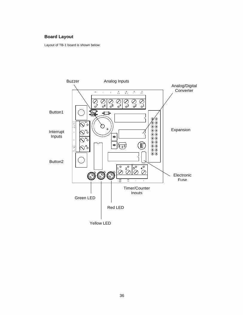
Board Layout Layout of TB-1 board is shown below:
Buzzer Analog Inputs Analog/Digital
Converter
Expansion
Electronic Fuse
Timer/Counter Inputs
Red LED
Green LED
Yellow LED
Button1
Interrupt Inputs
Button2

37
Functional Blocks Expansion TB-1 is connected to MINI-MAX/51-C2 and other boards through the Expansion Connector ( J1 ). Table 4 shows the pin assignments for the Expansion Connector.
Expansion (J1)
Signal Pin Pin Signal P3.0 20 19 P3.1 P3.2 18 17 P3.3 P3.4 16 15 P3.5 P3.6 14 13 P3.7 P1.0 12 11 P1.1 P1.2 10 9 P1.3 P1.4 8 7 P1.5 P1.6 6 5 P1.7 VCC 4 3 GND VCC 2 1 GND
Table 4
LED’s TB-1 has 3 Light Emitting Diodes ( LED’s ) that are connected in a traffic light pattern. Red and green LED’s are on each side and the yellow LED is in the middle. LED’s are driven by a 7407 buffer ( IC2 ). Each LED has two pins; cathode ( negative terminal ) and anode ( positive terminal ). The current through the LED’s are limited through current limiting resistors that tie the anode pins to Vcc. To turn an LED on, the cathode is pulled to ground through the corresponding gate of the 7407 buffer. To turn an LED off, the corresponding gate of the 7407 buffer is deactivated by setting the input of the gate to a logic high level.
38
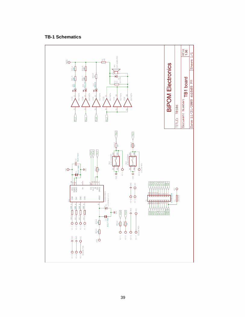
Buzzer Because the buzzer requires higher current than the LED’s, buzzer is driven by three 7407 buffer gates that are connected in parallel. Due of the inductive nature of the buzzer, a freewheeling diode ( D4 ) is used to clamp reverse voltages that may be induced on the buzzer when the buzzer is being turned on or off. Buttons There are 2 push buttons on the TB-1. Each button is connected through a protection resistor to an interrupt input ( P3.2 and P3.3 ) on the micro-controller. Pressing a button forces a logic low level on the corresponding micro-controller input. Interrupt Inputs AT89C51ED2 has port pins ( P3.2 and P3.3 ) that can be used either as general-purpose inputs/output or as interrupt inputs. A high to low logic transition or a low logic level on those inputs can cause a hardware interrupt to be generated. Timer/Counter Inputs AT89C51ED2 has port pins ( P3.4 and P3.5 ) that can be used either as general-purpose inputs/output or as timer/counter inputs. Logic level changes on these inputs can be counted by the timer hardware on the micro-controller eliminating the need for software polling loops. Analog/Digital Converter (ADC) TB-1 has a type ADC0834, 4-channel, 8-bit Analog/Digital converter. Analog inputs are available on X1 terminal block. Analog/Digital Converter is controlled by the micro-controller through 4 port lines. Chip Select (CS ) is an input to the ADC. Chip Select enables data conversion when it is logic low and disables data conversion when it is logic high. Clock is an input to the ADC. Mode of operation ( single-ended versus differential ) and channel number is entered through the DI pin one bit at a time ( on every transition of the Clock input ). The 8-bit data that corresponds to the voltage on the selected channel is output on DO one bit at a time ( on every transition of the Clock input ).
39
TB-1 Schematics
40
Advanced Project Ideas • Connecting a printer to the MicroTRAK: In this exercise, the student connects a parallel port printer
to the MINI-MAX/51-C2 board using available ports. Student then develops an 8051 program to print characters on the printer using DATA and STROBE lines.
• Using the MicroTRAK as a frequency counter: Student develops an 8051 program to measure the
frequency and/or period of an incoming signal using 8051’s interrupt inputs. The results are then displayed on the terminal window. Input signal is provided from a lab signal generator.
• Using the MicroTRAK as a temperature controller: Student develops an 8051 program to connect
LM35 or similar temperature sensor to the analog inputs. Depending on the temperature reading one of red, yellow or green LED’s are illuminated. If the temperature goes above a preset threshold, the buzzer sounds.
• Using the MicroTRAK EEPROM and the Analog-To-Digital Converter as a multi-channel data
logger.