pdf - complete book (1.39 mb)
TRANSCRIPT

Se nd do cume nt c ommen ts t o nex us3k -d oc fee dba ck@c i sc o . co m
Cisco Nexus 3000 Series NX-OS Multicast Routing Configuration Guide, Release 5.0(3)U1(1)May 2011
Americas HeadquartersCisco Systems, Inc.170 West Tasman DriveSan Jose, CA 95134-1706 USAhttp://www.cisco.comTel: 408 526-4000
800 553-NETS (6387)Fax: 408 527-0883
Text Part Number: OL-xxxxx-xx

Se nd do cume nt c ommen ts t o nex us3k -d oc fee dba ck@c i sc o . co m
THE SPECIFICATIONS AND INFORMATION REGARDING THE PRODUCTS IN THIS MANUAL ARE SUBJECT TO CHANGE WITHOUT NOTICE. ALL STATEMENTS, INFORMATION, AND RECOMMENDATIONS IN THIS MANUAL ARE BELIEVED TO BE ACCURATE BUT ARE PRESENTED WITHOUT WARRANTY OF ANY KIND, EXPRESS OR IMPLIED. USERS MUST TAKE FULL RESPONSIBILITY FOR THEIR APPLICATION OF ANY PRODUCTS.
THE SOFTWARE LICENSE AND LIMITED WARRANTY FOR THE ACCOMPANYING PRODUCT ARE SET FORTH IN THE INFORMATION PACKET THAT SHIPPED WITH THE PRODUCT AND ARE INCORPORATED HEREIN BY THIS REFERENCE. IF YOU ARE UNABLE TO LOCATE THE SOFTWARE LICENSE OR LIMITED WARRANTY, CONTACT YOUR CISCO REPRESENTATIVE FOR A COPY.
The Cisco implementation of TCP header compression is an adaptation of a program developed by the University of California, Berkeley (UCB) as part of UCB’s public domain version of the UNIX operating system. All rights reserved. Copyright © 1981, Regents of the University of California.
NOTWITHSTANDING ANY OTHER WARRANTY HEREIN, ALL DOCUMENT FILES AND SOFTWARE OF THESE SUPPLIERS ARE PROVIDED “AS IS” WITH ALL FAULTS. CISCO AND THE ABOVE-NAMED SUPPLIERS DISCLAIM ALL WARRANTIES, EXPRESSED OR IMPLIED, INCLUDING, WITHOUT LIMITATION, THOSE OF MERCHANTABILITY, FITNESS FOR A PARTICULAR PURPOSE AND NONINFRINGEMENT OR ARISING FROM A COURSE OF DEALING, USAGE, OR TRADE PRACTICE.
IN NO EVENT SHALL CISCO OR ITS SUPPLIERS BE LIABLE FOR ANY INDIRECT, SPECIAL, CONSEQUENTIAL, OR INCIDENTAL DAMAGES, INCLUDING, WITHOUT LIMITATION, LOST PROFITS OR LOSS OR DAMAGE TO DATA ARISING OUT OF THE USE OR INABILITY TO USE THIS MANUAL, EVEN IF CISCO OR ITS SUPPLIERS HAVE BEEN ADVISED OF THE POSSIBILITY OF SUCH DAMAGES.
Cisco and the Cisco Logo are trademarks of Cisco Systems, Inc. and/or its affiliates in the U.S. and other countries. A listing of Cisco's trademarks can be found at www.cisco.com/go/trademarks. Third party trademarks mentioned are the property of their respective owners. The use of the word partner does not imply a partnership relationship between Cisco and any other company. (1005R)
Any Internet Protocol (IP) addresses used in this document are not intended to be actual addresses. Any examples, command display output, and figures included in the document are shown for illustrative purposes only. Any use of actual IP addresses in illustrative content is unintentional and coincidental.
Cisco Nexus 3000 Series NX-OS Multicast Routing Configuration Guide, Release 5.0(3)U1(1)© 2011 Cisco Systems, Inc. All rights reserved.
Se nd do cume nt c ommen ts t o nex us3k -d oc fee dba ck@c i sc o . co m
Cisco NexuOL-xxxxx-xx
C O N T E N T S
Preface ix
Audience ix
Supported Switches ix
Cisco Nexus 3000 Platform Switches ix
Organization x
Document Conventions x
Related Documentation xi
Release Notes xi
Configuration Guides xi
Maintain and Operate Guides xii
Installation and Upgrade Guides xii
Licensing Guide xii
Command References xii
Technical References xii
Error and System Messages xii
Troubleshooting Guide xii
Obtaining Documentation and Submitting a Service Request xiii
C H A P T E R 1 Overview 1-1
Information About Multicast 1-1
Multicast Distribution Trees 1-2
Source Trees 1-2
Shared Trees 1-3
Multicast Forwarding 1-4
Cisco NX-OS PIM 1-5
ASM 1-7
SSM 1-7
RPF Routes for Multicast 1-7
IGMP 1-7
IGMP Snooping 1-8
Interdomain Multicast 1-8
SSM 1-8
MSDP 1-8
MRIB 1-8
iiis 3000 Series NX-OS Multicast Routing Configuration Guide, Release 5.0(3)U1(1)
Se nd do cume nt c ommen ts t o nex us3k -d oc fee dba ck@c i sc o . co m
Contents
Licensing Requirements for Multicast 1-9
Additional References 1-10
Related Documents 1-10
Technical Assistance 1-10
C H A P T E R 2 Configuring IGMP 2-1
Information About IGMP 2-1
IGMP Versions 2-2
IGMP Basics 2-2
Virtualization Support 2-4
Licensing Requirements for IGMP 2-4
Default Settings for IGMP 2-5
Configuring IGMP Parameters 2-5
Configuring IGMP Interface Parameters 2-5
Configuring an IGMP SSM Translation 2-11
Configuring the Enforce Router Alert Option Check 2-12
Verifying the IGMP Configuration 2-13
Configuration Examples for IGMP 2-14
Where to Go Next 2-14
Feature History for IGMP 2-15
C H A P T E R 3 Configuring PIM 3-1
Information About PIM 3-1
Hello Messages 3-2
Join-Prune Messages 3-3
State Refreshes 3-3
Rendezvous Points 3-4
Static RP 3-4
BSRs 3-4
Auto-RP 3-5
Anycast-RP 3-6
PIM Register Messages 3-7
Designated Routers 3-7
Administratively Scoped IP Multicast 3-7
Virtualization Support 3-8
Licensing Requirements for PIM 3-8
Guidelines and Limitations for PIM 3-8
Default Settings 3-8
ivCisco Nexus 3000 Series NX-OS Multicast Routing Configuration Guide, Release 5.0(3)U1(1)
OL-xxxxx-xx
Se nd do cume nt c ommen ts t o nex us3k -d oc fee dba ck@c i sc o . co m
Contents
Configuring PIM 3-9
Enabling the PIM Features 3-10
Configuring PIM Sparse Mode 3-11
Configuring ASM 3-15
Configuring Static RPs 3-15
Configuring BSRs 3-16
Configuring Auto-RP 3-19
Configuring a PIM Anycast-RP Set 3-21
Configuring Shared Trees Only for ASM 3-23
Configuring SSM 3-24
3-25
Setting the Maximum Number of Entries in the Multicast Routing Table 3-25
Configuring RPF Routes for Multicast 3-26
Configuring Route Maps to Control RP Information Distribution 3-27
Configuring Message Filtering 3-28
Verifying the PIM Configuration 3-32
Displaying Statistics 3-33
Displaying PIM Statistics 3-33
Clearing PIM Statistics 3-33
Configuration Examples for PIM 3-34
Configuration Example for SSM 3-34
Configuration Example for BSR 3-35
Configuration Example for PIM Anycast-RP 3-36
Where to Go Next 3-37
Additional References 3-37
Related Documents 3-37
Standards 3-37
MIBs 3-37
Feature History for PIM 3-38
C H A P T E R 4 Configuring IGMP Snooping 4-1
Information About IGMP Snooping 4-1
IGMPv1 and IGMPv2 4-2
IGMPv3 4-3
IGMP Snooping Querier 4-3
IGMP Filtering on Router Ports 4-3
IGMP Snooping with VRFs 4-3
Licensing Requirements for IGMP Snooping 4-4
Prerequisites for IGMP Snooping 4-4
vCisco Nexus 3000 Series NX-OS Multicast Routing Configuration Guide, Release 5.0(3)U1(1)
OL-xxxxx-xx
Se nd do cume nt c ommen ts t o nex us3k -d oc fee dba ck@c i sc o . co m
Contents
Default Settings 4-4
Configuring IGMP Snooping Parameters 4-5
Verifying the IGMP Snooping Configuration 4-7
Displaying IGMP Snooping Statistics 4-8
Configuration Examples for IGMP Snooping 4-8
Where to Go Next 4-8
Additional References 4-8
Related Documents 4-9
Standards 4-9
Feature History for IGMP Snooping 4-9
C H A P T E R 5 Configuring MSDP 5-1
Information About MSDP 5-1
SA Messages and Caching 5-2
MSDP Peer-RPF Forwarding 5-3
MSDP Mesh Groups 5-3
Virtualization Support 5-3
Licensing Requirements for MSDP 5-3
Prerequisites for MSDP 5-4
Default Settings 5-4
Configuring MSDP 5-4
Enabling the MSDP Feature 5-5
Configuring MSDP Peers 5-6
Configuring MSDP Peer Parameters 5-7
Configuring MSDP Global Parameters 5-10
Configuring MSDP Mesh Groups 5-11
Restarting the MSDP Process 5-12
Verifying the MSDP Configuration 5-13
Displaying Statistics 5-14
Displaying Statistics 5-14
Clearing Statistics 5-14
Configuration Examples for MSDP 5-15
Additional References 5-16
Related Documents 5-16
Standards 5-16
Feature History for IGMP 5-16
viCisco Nexus 3000 Series NX-OS Multicast Routing Configuration Guide, Release 5.0(3)U1(1)
OL-xxxxx-xx

Se nd do cume nt c ommen ts t o nex us3k -d oc fee dba ck@c i sc o . co m
Contents
A P P E N D I X A IETF RFCs for IP Multicast A-1
viiCisco Nexus 3000 Series NX-OS Multicast Routing Configuration Guide, Release 5.0(3)U1(1)
OL-xxxxx-xx

Se nd do cume nt c ommen ts t o nex us3k -d oc fee dba ck@c i sc o . co m
Contents
viiiCisco Nexus 3000 Series NX-OS Multicast Routing Configuration Guide, Release 5.0(3)U1(1)
OL-xxxxx-xx
Se nd do cume nt c ommen ts t o nex us3k -d oc fee dba ck@c i sc o . co m
Preface
This preface describes the audience, organization, and conventions of the Cisco Nexus 3000 Series NX-OS Multicast Routing Configuration Guide, Release 5.0(3)U1(1). It also provides information on how to obtain related documentation.
This chapter includes the following sections:
• Audience, page ix
• Supported Switches, page ix
• Organization, page x
• Document Conventions, page x
• Related Documentation, page xi
• Obtaining Documentation and Submitting a Service Request, page xiii
AudienceTo use this guide, you must be familiar with IP and routing technology.
Supported SwitchesThis section includes the following topics:
• Cisco Nexus 3000 Platform Switches, page ix
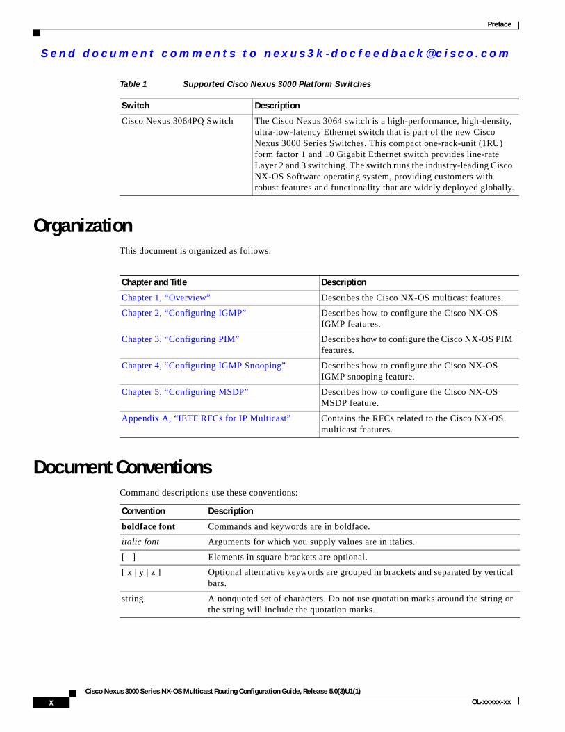
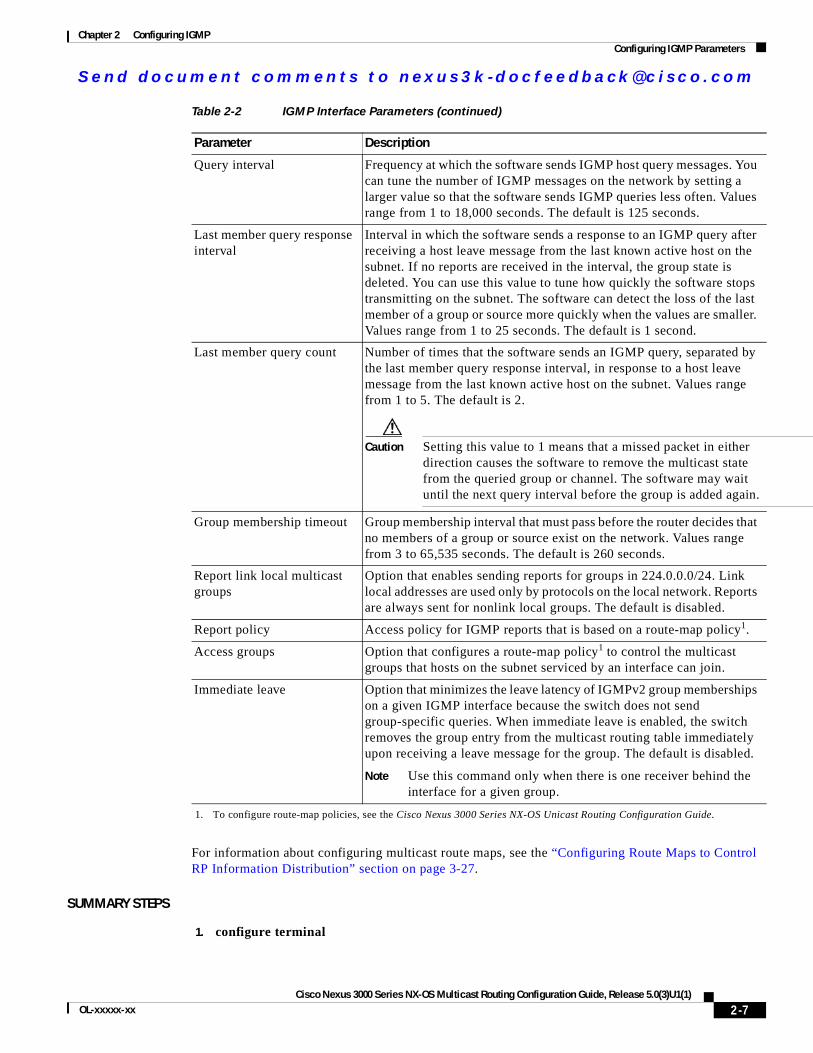
Cisco Nexus 3000 Platform SwitchesTable 1 describes the Cisco Nexus 3000 Series switch:
Note For more information about the Cisco Nexus 3000 Series, see the Cisco Nexus 3000 Series Hardware Installation Guide available at the following URL:http://www.cisco.com/en/US/products/ps9670/tsd_products_support_series_home.html
ixCisco Nexus 3000 Series NX-OS Multicast Routing Configuration Guide, Release 5.0(3)U1(1)
OL-xxxxx-xx
Se nd do cume nt c ommen ts t o nex us3k -d oc fee dba ck@c i sc o . co m
Preface
OrganizationThis document is organized as follows:
Document ConventionsCommand descriptions use these conventions:
Table 1 Supported Cisco Nexus 3000 Platform Switches
Switch Description
Cisco Nexus 3064PQ Switch The Cisco Nexus 3064 switch is a high-performance, high-density, ultra-low-latency Ethernet switch that is part of the new Cisco Nexus 3000 Series Switches. This compact one-rack-unit (1RU) form factor 1 and 10 Gigabit Ethernet switch provides line-rate Layer 2 and 3 switching. The switch runs the industry-leading Cisco NX-OS Software operating system, providing customers with robust features and functionality that are widely deployed globally.
Chapter and Title Description
Chapter 1, “Overview” Describes the Cisco NX-OS multicast features.
Chapter 2, “Configuring IGMP” Describes how to configure the Cisco NX-OS IGMP features.
Chapter 3, “Configuring PIM” Describes how to configure the Cisco NX-OS PIM features.
Chapter 4, “Configuring IGMP Snooping” Describes how to configure the Cisco NX-OS IGMP snooping feature.
Chapter 5, “Configuring MSDP” Describes how to configure the Cisco NX-OS MSDP feature.
Appendix A, “IETF RFCs for IP Multicast” Contains the RFCs related to the Cisco NX-OS multicast features.
Convention Description
boldface font Commands and keywords are in boldface.
italic font Arguments for which you supply values are in italics.
[ ] Elements in square brackets are optional.
[ x | y | z ] Optional alternative keywords are grouped in brackets and separated by vertical bars.
string A nonquoted set of characters. Do not use quotation marks around the string or the string will include the quotation marks.
xCisco Nexus 3000 Series NX-OS Multicast Routing Configuration Guide, Release 5.0(3)U1(1)
OL-xxxxx-xx
Se nd do cume nt c ommen ts t o nex us3k -d oc fee dba ck@c i sc o . co m
Preface
Screen examples use these conventions:
This document uses the following conventions:
Note Means reader take note. Notes contain helpful suggestions or references to material not covered in the manual.
Caution Means reader be careful. In this situation, you might do something that could result in equipment damage or loss of data.
Tip Means the following information will help you solve a problem.
Related DocumentationDocumentation for Cisco Nexus 3000 Series Switches and Cisco Nexus 2000 Series Fabric Extender is available at the following URL:
http://www.cisco.com/en/US/products/ps9670/tsd_products_support_series_home.html
The following are related Cisco Nexus 3000 Series documents:
Release NotesCisco Nexus 3000 Series Release Notes
Configuration GuidesCisco Nexus 3000 Series Configuration Limits for Cisco NX-OS Release 5.0(3)U1(1)
Cisco Nexus 3000 Series NX-OS Layer 2 Switching Configuration Guide
Cisco Nexus 3000 Series NX-OS Multicast Routing Configuration Guide
Cisco Nexus 3000 Series NX-OS Quality of Service Configuration Guide
Cisco Nexus 3000 Series NX-OS SAN Switching Configuration Guide
screen font Terminal sessions and information that the switch displays are in screen font.
boldface screen font
Information you must enter is in boldface screen font.
italic screen font Arguments for which you supply values are in italic screen font.
< > Nonprinting characters, such as passwords, are in angle brackets.
[ ] Default responses to system prompts are in square brackets.
!, # An exclamation point (!) or a pound sign (#) at the beginning of a line of code indicates a comment line.
xiCisco Nexus 3000 Series NX-OS Multicast Routing Configuration Guide, Release 5.0(3)U1(1)
OL-xxxxx-xx
Se nd do cume nt c ommen ts t o nex us3k -d oc fee dba ck@c i sc o . co m
Preface
Cisco Nexus 3000 Series NX-OS Security Configuration Guide
Cisco Nexus 3000 Series NX-OS System Management Configuration Guide
Cisco Nexus 3000 Series NX-OS Unicast Routing Configuration Guide
Cisco NX-OS Fundamentals Configuration Guide
Maintain and Operate GuidesCisco Nexus 3000 Series NX-OS Operations Guide
Installation and Upgrade GuidesCisco Nexus 3000 Series Hardware Installation Guide
Regulatory, Compliance, and Safety Information for the Cisco Nexus 5000 Series, Cisco Nexus 3000 Series, and Cisco Nexus 2000 Series
Licensing GuideCisco NX-OS Licensing Guide
Command ReferencesCisco Nexus 3000 Series Command Reference
Technical ReferencesCisco Nexus 3000 Series MIBs Reference
Error and System MessagesCisco NX-OS System Messages Reference
Troubleshooting GuideCisco Nexus 3000 Troubleshooting Guide
xiiCisco Nexus 3000 Series NX-OS Multicast Routing Configuration Guide, Release 5.0(3)U1(1)
OL-xxxxx-xx
Se nd do cume nt c ommen ts t o nex us3k -d oc fee dba ck@c i sc o . co m
Preface
Obtaining Documentation and Submitting a Service RequestFor information on obtaining documentation, submitting a service request, and gathering additional information, see the monthly What’s New in Cisco Product Documentation, which also lists all new and revised Cisco technical documentation, at:
http://www.cisco.com/en/US/docs/general/whatsnew/whatsnew.html
Subscribe to the What’s New in Cisco Product Documentation as an RSS feed and set content to be delivered directly to your desktop using a reader application. The RSS feeds are a free service. Cisco currently supports RSS Version 2.0.
xiiiCisco Nexus 3000 Series NX-OS Multicast Routing Configuration Guide, Release 5.0(3)U1(1)
OL-xxxxx-xx

Se nd do cume nt c ommen ts t o nex us3k -d oc fee dba ck@c i sc o . co m
Preface
xivCisco Nexus 3000 Series NX-OS Multicast Routing Configuration Guide, Release 5.0(3)U1(1)
OL-xxxxx-xx
Se nd do cume nt c ommen ts t o nex us3k -d oc fee dba ck@c i sc o . co m
Cisco Nexus 3000 Series NX-OS MulticaOL-xxxxx-xx
C H A P T E R 1
OverviewThis chapter describes the multicast features of Cisco NX-OS.
This chapter includes the following sections:
• Information About Multicast, page 1-1
• Licensing Requirements for Multicast, page 1-9
• Additional References, page 1-10
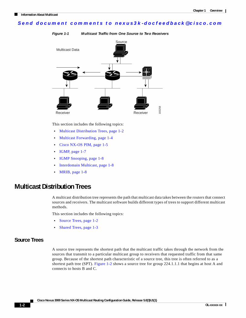
Information About MulticastIP multicast is a method of forwarding the same set of IP packets to a number of hosts within a network. You can use multicast in IPv4 networks to provide efficient delivery of data to multiple destinations.
Multicast involves both a method of delivery and discovery of senders and receivers of multicast data, which is transmitted on IP multicast addresses called groups. A multicast address that includes a group and source IP address is often referred to as a channel. The Internet Assigned Number Authority (IANA) has assigned 224.0.0.0 through 239.255.255.255 as IPv4 multicast addresses. For more information, see http://www.iana.org/assignments/multicast-addresses.
Note For a complete list of RFCs related to multicast, see Appendix A, “IETF RFCs for IP Multicast.”
The routers in the network listen for receivers to advertise their interest in receiving multicast data from selected groups. The routers then replicate and forward the data from sources to the interested receivers. Multicast data for a group is transmitted only to those LAN segments with receivers that requested it.
Figure 1-1 shows one source transmitting multicast data that is delivered to two receivers. In the figure, because the center host is on a LAN segment where no receiver requested multicast data, no data is delivered to that receiver.
1-1st Routing Configuration Guide, Release 5.0(3)U1(1)
Se nd do cume nt c ommen ts t o nex us3k -d oc fee dba ck@c i sc o . co m
Chapter 1 OverviewInformation About Multicast
Figure 1-1 Multicast Traffic from One Source to Two Receivers
This section includes the following topics:
• Multicast Distribution Trees, page 1-2
• Multicast Forwarding, page 1-4
• Cisco NX-OS PIM, page 1-5
• IGMP, page 1-7
• IGMP Snooping, page 1-8
• Interdomain Multicast, page 1-8
• MRIB, page 1-8
Multicast Distribution TreesA multicast distribution tree represents the path that multicast data takes between the routers that connect sources and receivers. The multicast software builds different types of trees to support different multicast methods.
This section includes the following topics:
• Source Trees, page 1-2
• Shared Trees, page 1-3
Source Trees
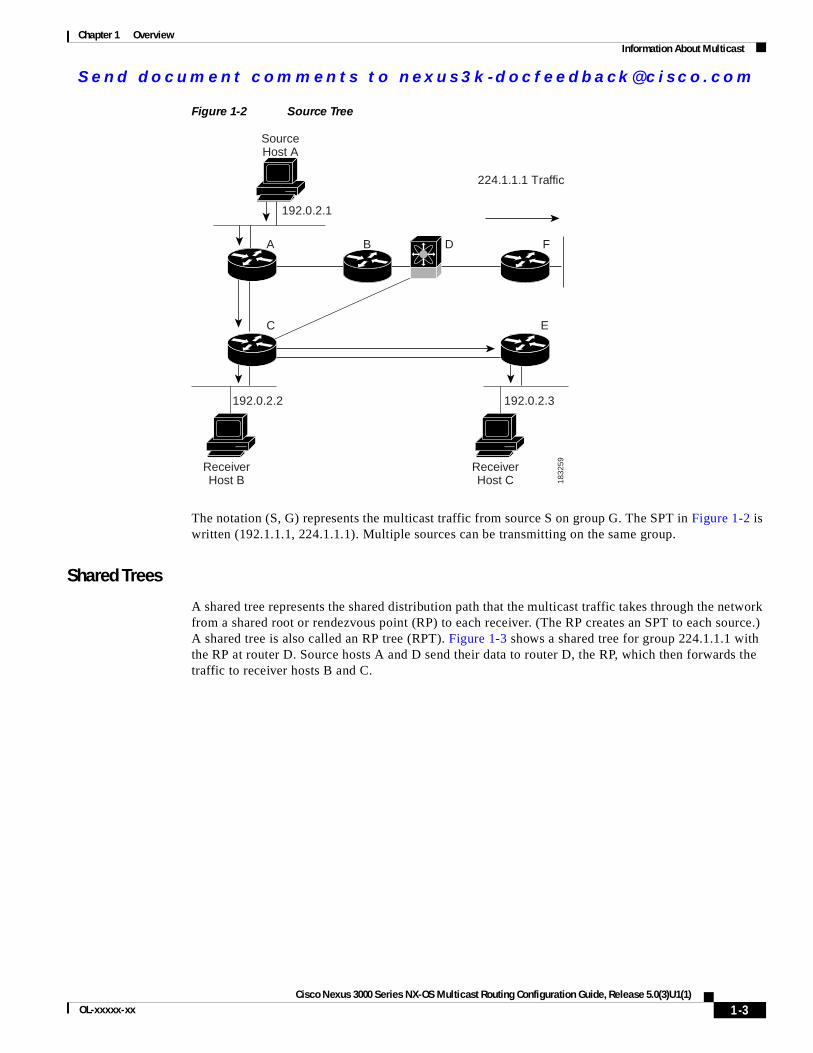
A source tree represents the shortest path that the multicast traffic takes through the network from the sources that transmit to a particular multicast group to receivers that requested traffic from that same group. Because of the shortest path characteristic of a source tree, this tree is often referred to as a shortest path tree (SPT). Figure 1-2 shows a source tree for group 224.1.1.1 that begins at host A and connects to hosts B and C.
Multicast Data
Source
Receiver Receiver 1832
58
1-2Cisco Nexus 3000 Series NX-OS Multicast Routing Configuration Guide, Release 5.0(3)U1(1)
OL-xxxxx-xx
Se nd do cume nt c ommen ts t o nex us3k -d oc fee dba ck@c i sc o . co m
Chapter 1 OverviewInformation About Multicast
Figure 1-2 Source Tree
The notation (S, G) represents the multicast traffic from source S on group G. The SPT in Figure 1-2 is written (192.1.1.1, 224.1.1.1). Multiple sources can be transmitting on the same group.
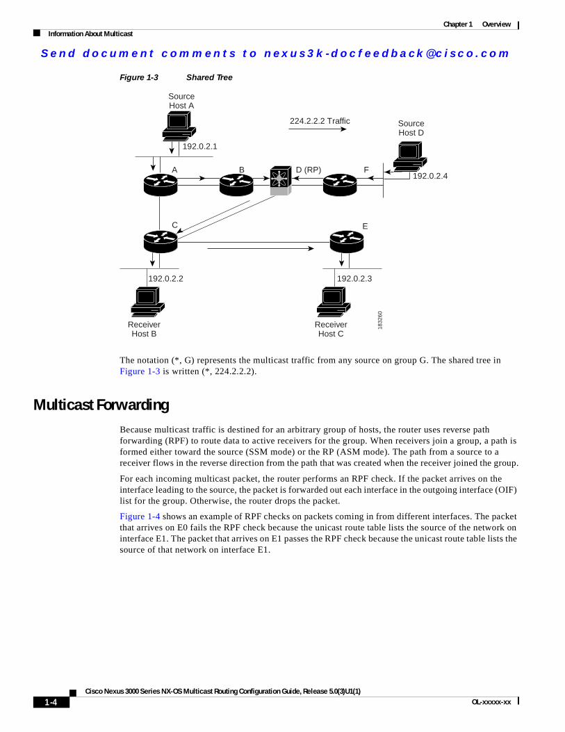
Shared Trees
A shared tree represents the shared distribution path that the multicast traffic takes through the network from a shared root or rendezvous point (RP) to each receiver. (The RP creates an SPT to each source.) A shared tree is also called an RP tree (RPT). Figure 1-3 shows a shared tree for group 224.1.1.1 with the RP at router D. Source hosts A and D send their data to router D, the RP, which then forwards the traffic to receiver hosts B and C.
SourceHost A
ReceiverHost B
ReceiverHost C 18
3259
192.0.2.1
192.0.2.2 192.0.2.3
224.1.1.1 Traffic
A
C E
B FD
1-3Cisco Nexus 3000 Series NX-OS Multicast Routing Configuration Guide, Release 5.0(3)U1(1)
OL-xxxxx-xx
Se nd do cume nt c ommen ts t o nex us3k -d oc fee dba ck@c i sc o . co m
Chapter 1 OverviewInformation About Multicast
Figure 1-3 Shared Tree
The notation (*, G) represents the multicast traffic from any source on group G. The shared tree in Figure 1-3 is written (*, 224.2.2.2).
Multicast ForwardingBecause multicast traffic is destined for an arbitrary group of hosts, the router uses reverse path forwarding (RPF) to route data to active receivers for the group. When receivers join a group, a path is formed either toward the source (SSM mode) or the RP (ASM mode). The path from a source to a receiver flows in the reverse direction from the path that was created when the receiver joined the group.
For each incoming multicast packet, the router performs an RPF check. If the packet arrives on the interface leading to the source, the packet is forwarded out each interface in the outgoing interface (OIF) list for the group. Otherwise, the router drops the packet.
Figure 1-4 shows an example of RPF checks on packets coming in from different interfaces. The packet that arrives on E0 fails the RPF check because the unicast route table lists the source of the network on interface E1. The packet that arrives on E1 passes the RPF check because the unicast route table lists the source of that network on interface E1.
SourceHost A
SourceHost D
ReceiverHost B
ReceiverHost C
1832
60
192.0.2.1
192.0.2.4
192.0.2.2 192.0.2.3
224.2.2.2 Traffic
A
C E
B FD (RP)
1-4Cisco Nexus 3000 Series NX-OS Multicast Routing Configuration Guide, Release 5.0(3)U1(1)
OL-xxxxx-xx

Se nd do cume nt c ommen ts t o nex us3k -d oc fee dba ck@c i sc o . co m
Chapter 1 OverviewInformation About Multicast
Figure 1-4 RPF Check Example
Cisco NX-OS PIMCisco NX-OS supports multicasting with Protocol Independent Multicast (PIM) sparse mode. PIM is IP routing protocol independent and can leverage whichever unicast routing protocols are used to populate the unicast routing table. In PIM sparse mode, multicast traffic is sent only to locations of the network that specifically request it. PIM dense mode is not supported by Cisco NX-OS.
Note In this publication, the term “PIM” is used for PIM sparse mode version 2.
To access multicast commands, you must enable the PIM feature. Multicast is enabled only after you enable PIM on an interface of each router in a domain. You configure PIM for an IPv4 network. By default, IGMP runs on the system.
PIM, which is used between multicast-capable routers, advertises group membership across a routing domain by constructing multicast distribution trees. PIM builds shared distribution trees on which packets from multiple sources are forwarded, as well as source distribution trees, on which packets from a single source are forwarded.
The distribution trees change automatically to reflect the topology changes due to link or router failures. PIM dynamically tracks both multicast-capable sources and receivers.
The router uses the unicast routing table and RPF routes for multicast to create multicast routing information.
Note In this publication, “PIM for IPv4” refer to the Cisco NX-OS implementation of PIM sparse mode. A PIM domain can include an IPv4 network.
E1209.165.200.224/27
E0192.0.2.0/24
InterfaceNetwork
Unicast Route Table
E1209.165.200.224/27
E0192.0.2.0/24
InterfaceNetwork
Unicast packet from source 209.165.200.225RPF check fails
Unicast packet from source 209.165.200.225RPF check succeeds
E0
E1
1832
62
1-5Cisco Nexus 3000 Series NX-OS Multicast Routing Configuration Guide, Release 5.0(3)U1(1)
OL-xxxxx-xx
Se nd do cume nt c ommen ts t o nex us3k -d oc fee dba ck@c i sc o . co m
Chapter 1 OverviewInformation About Multicast
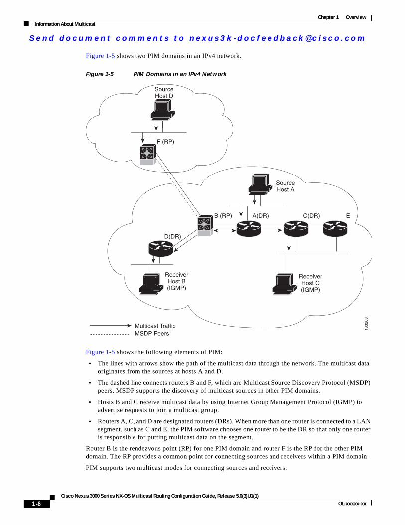
Figure 1-5 shows two PIM domains in an IPv4 network.
Figure 1-5 PIM Domains in an IPv4 Network
Figure 1-5 shows the following elements of PIM:
• The lines with arrows show the path of the multicast data through the network. The multicast data originates from the sources at hosts A and D.
• The dashed line connects routers B and F, which are Multicast Source Discovery Protocol (MSDP) peers. MSDP supports the discovery of multicast sources in other PIM domains.
• Hosts B and C receive multicast data by using Internet Group Management Protocol (IGMP) to advertise requests to join a multicast group.
• Routers A, C, and D are designated routers (DRs). When more than one router is connected to a LAN segment, such as C and E, the PIM software chooses one router to be the DR so that only one router is responsible for putting multicast data on the segment.
Router B is the rendezvous point (RP) for one PIM domain and router F is the RP for the other PIM domain. The RP provides a common point for connecting sources and receivers within a PIM domain.
PIM supports two multicast modes for connecting sources and receivers:
SourceHost A
SourceHost D
ReceiverHost B(IGMP)
ReceiverHost C(IGMP)
18
32
63
Multicast Traffic
MSDP Peers
D(DR)
B (RP)
F (RP)
EC(DR)A(DR)
1-6Cisco Nexus 3000 Series NX-OS Multicast Routing Configuration Guide, Release 5.0(3)U1(1)
OL-xxxxx-xx
Se nd do cume nt c ommen ts t o nex us3k -d oc fee dba ck@c i sc o . co m
Chapter 1 OverviewInformation About Multicast
• Any source multicast (ASM)
• Source-specific multicast (SSM)
Cisco NX-OS supports a combination of these modes for different ranges of multicast groups. You can also define RPF routes for multicast.
This section includes the following topics:
• ASM, page 1-7
• SSM, page 1-7
• RPF Routes for Multicast, page 1-7
ASM
Any Source Multicast (ASM) is a PIM tree building mode that uses shared trees to discover new sources and receivers as well as source trees to form shortest paths from receivers to sources. The shared tree uses a network node as the root, called the rendezvous point (RP). The source tree is rooted at first-hop routers, directly attached to each source that is an active sender. The ASM mode requires an RP for a group range. An RP can be configured statically or learned dynamically by the Auto-RP or BSR group-to-RP discovery protocols.
The ASM mode is the default mode when you configure RPs.
For information about configuring ASM, see the “Configuring ASM” section on page 3-15.
SSM
Source-Specific Multicast (SSM) is a PIM mode that builds a source tree that originates at the designated router on the LAN segment that receives a request to join a multicast source. Source trees are built by sending PIM join messages in the direction of the source. The SSM mode does not require you to configure RPs.
The SSM mode allows receivers to connect to sources outside the PIM domain.
For information about configuring SSM, see the “Configuring SSM” section on page 3-24.
RPF Routes for Multicast
You can configure static multicast RPF routes to override what the unicast routing table uses. This feature is used when the multicast topology is different than the unicast topology.
For information about configuring RPF routes for multicast, see the “Configuring RPF Routes for Multicast” section on page 3-26.
IGMPBy default, the Internet Group Management Protocol (IGMP) for PIM is running on the system.
The IGMP protocol is used by hosts that want to receive multicast data to request membership in multicast groups. Once the group membership is established, multicast data for the group is directed to the LAN segment of the requesting host.
You can configure IGMPv2 or IGMPv3 on an interface. You will usually configure IGMPv3 to support SSM mode. By default, the software enables IGMPv2.
1-7Cisco Nexus 3000 Series NX-OS Multicast Routing Configuration Guide, Release 5.0(3)U1(1)
OL-xxxxx-xx
Se nd do cume nt c ommen ts t o nex us3k -d oc fee dba ck@c i sc o . co m
Chapter 1 OverviewInformation About Multicast
For information about configuring IGMP, see Chapter 2, “Configuring IGMP”.
IGMP SnoopingIGMP snooping is a feature that limits multicast traffic on VLANs to the subset of ports that have known receivers. By examining (snooping) IGMP membership report messages from interested hosts, multicast traffic is sent only to VLAN ports that interested hosts reside on. By default, IGMP snooping is running on the system.
For information about configuring IGMP snooping, see Chapter 4, “Configuring IGMP Snooping.”
Interdomain MulticastCisco NX-OS provides several methods that allow multicast traffic to flow between PIM domains.
This section includes the following topics:
• SSM, page 1-8
• MSDP, page 1-8
SSM
The PIM software uses SSM to construct a shortest path tree from the designated router for the receiver to a known source IP address, which may be in another PIM domain. The ASM mode cannot access sources from another PIM domain without the use of another protocol.
Once you enable PIM in your networks, you can use SSM to reach any multicast source that has an IP address known to the designated router for the receiver.
For information about configuring SSM, see the “Configuring SSM” section on page 3-24.
MSDP
Multicast Source Discovery Protocol (MSDP) is a multicast routing protocol that is used with PIM to support the discovery of multicast sources in different PIM domains.
Note Cisco NX-OS supports the PIM Anycast-RP, which does not require MSDP configuration. For information about PIM Anycast-RP, see the “Configuring a PIM Anycast-RP Set” section on page 3-21.
For information about MSDP, see Chapter 5, “Configuring MSDP.”
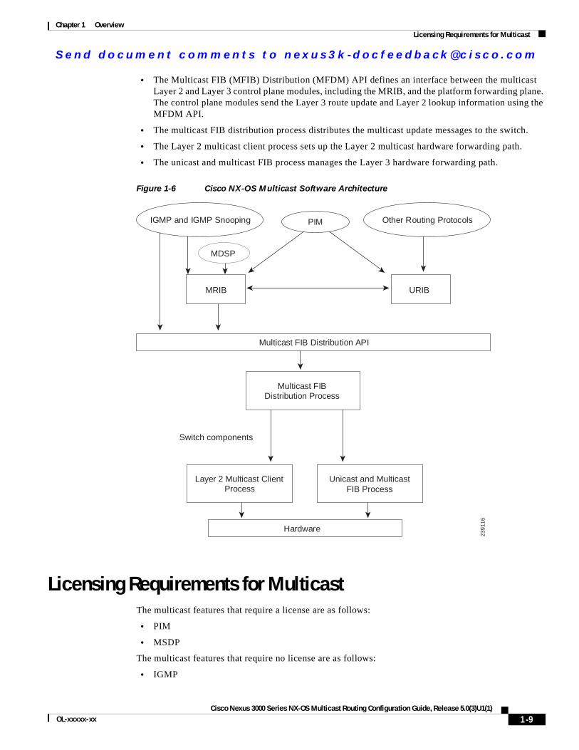
MRIBThe Cisco NX-OS IPv4 Multicast Routing Information Base (MRIB) is a repository for route information that is generated by multicast protocols such as PIM and IGMP. The MRIB does not affect the route information itself. The MRIB maintains independent route information for each virtual routing and forwarding (VRF) instance.
Figure 1-6 shows the major components of the Cisco NX-OS multicast software architecture:
1-8Cisco Nexus 3000 Series NX-OS Multicast Routing Configuration Guide, Release 5.0(3)U1(1)
OL-xxxxx-xx
Se nd do cume nt c ommen ts t o nex us3k -d oc fee dba ck@c i sc o . co m
Chapter 1 OverviewLicensing Requirements for Multicast
• The Multicast FIB (MFIB) Distribution (MFDM) API defines an interface between the multicast Layer 2 and Layer 3 control plane modules, including the MRIB, and the platform forwarding plane. The control plane modules send the Layer 3 route update and Layer 2 lookup information using the MFDM API.
• The multicast FIB distribution process distributes the multicast update messages to the switch.
• The Layer 2 multicast client process sets up the Layer 2 multicast hardware forwarding path.
• The unicast and multicast FIB process manages the Layer 3 hardware forwarding path.
Figure 1-6 Cisco NX-OS Multicast Software Architecture
Licensing Requirements for MulticastThe multicast features that require a license are as follows:
• PIM
• MSDP
The multicast features that require no license are as follows:
• IGMP
MRIB URIB
Multicast FIB Distribution API
IGMP and IGMP Snooping PIM Other Routing Protocols
Multicast FIB Distribution Process
L
Switch components
ayer 2 Multicast Client Process
Unicast and MulticastFIB Process
Hardware
2391
16
MDSP
1-9Cisco Nexus 3000 Series NX-OS Multicast Routing Configuration Guide, Release 5.0(3)U1(1)
OL-xxxxx-xx
Se nd do cume nt c ommen ts t o nex us3k -d oc fee dba ck@c i sc o . co m
Chapter 1 OverviewAdditional References
• IGMP snooping
For a complete explanation of the Cisco NX-OS licensing scheme, see the Cisco NX-OS Licensing Guide.
Additional ReferencesFor additional information related to implementing multicast, see the following sections:
• Related Documents, page 1-10
• Appendix A, “IETF RFCs for IP Multicast”
• Technical Assistance, page 1-10
Related Documents
Technical Assistance
Related Topic Document Title
CLI Commands Cisco Nexus 3000 Series Command Reference,
Description Link
Technical Assistance Center (TAC) home page, containing 30,000 pages of searchable technical content, including links to products, technologies, solutions, technical tips, and tools. Registered Cisco.com users can log in from this page to access even more content.
http://www.cisco.com/public/support/tac/home.shtml
1-10Cisco Nexus 3000 Series NX-OS Multicast Routing Configuration Guide, Release 5.0(3)U1(1)
OL-xxxxx-xx
Se nd do cume nt c ommen ts t o nex us3k -d oc fee dba ck@c i sc o . co m
Cisco Nexus 3000 Series NX-OS MulticaOL-xxxxx-xx
C H A P T E R 2
Configuring IGMPThis chapter describes how to configure the Internet Group Management Protocol (IGMP) on Cisco NX-OS switches for IPv4 networks.
This chapter includes the following sections:
• Information About IGMP, page 2-1
• Licensing Requirements for IGMP, page 2-4
• Default Settings for IGMP, page 2-5
• Configuring IGMP Parameters, page 2-5
• Verifying the IGMP Configuration, page 2-13
• Configuration Examples for IGMP, page 2-14
• Where to Go Next, page 2-14
• Feature History for IGMP, page 2-15
Information About IGMPIGMP is an IPv4 protocol that a host uses to request multicast data for a particular group. Using the information obtained through IGMP, the software maintains a list of multicast group or channel memberships on a per-interface basis. The systems that receive these IGMP packets send multicast data that they receive for requested groups or channels out the network segment of the known receivers.
By default, the IGMP process is running. You cannot enable IGMP manually on an interface. IGMP is automatically enabled when you perform one of the following configuration tasks on an interface:
• Enable PIM
• Statically bind a local multicast group
• Enable link-local group reports
This section includes the following topics:
• IGMP Versions, page 2-2
• IGMP Basics, page 2-2
• Virtualization Support, page 2-4
2-1st Routing Configuration Guide, Release 5.0(3)U1(1)
Se nd do cume nt c ommen ts t o nex us3k -d oc fee dba ck@c i sc o . co m
Chapter 2 Configuring IGMPInformation About IGMP
IGMP VersionsThe switch supports IGMPv2 and IGMPv3, as well as IGMPv1 report reception.
By default, the software enables IGMPv2 when it starts the IGMP process. You can enable IGMPv3 on interfaces where you want its capabilities.
IGMPv3 includes the following key changes from IGMPv2:
• Support for Source-Specific Multicast (SSM), which builds shortest path trees from each receiver to the source, through the following features:
– Host messages that can specify both the group and the source.
– The multicast state that is maintained for groups and sources, not just for groups as in IGMPv2.
• Hosts no longer perform report suppression, which means that hosts always send IGMP membership reports when an IGMP query message is received.
For detailed information about IGMPv2, see RFC 2236.
For detailed information about IGMPv3, see RFC 3376.
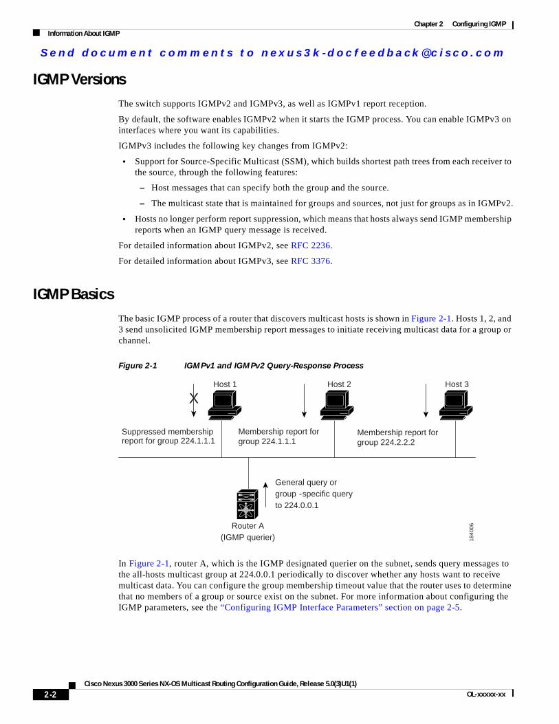
IGMP BasicsThe basic IGMP process of a router that discovers multicast hosts is shown in Figure 2-1. Hosts 1, 2, and 3 send unsolicited IGMP membership report messages to initiate receiving multicast data for a group or channel.
Figure 2-1 IGMPv1 and IGMPv2 Query-Response Process
In Figure 2-1, router A, which is the IGMP designated querier on the subnet, sends query messages to the all-hosts multicast group at 224.0.0.1 periodically to discover whether any hosts want to receive multicast data. You can configure the group membership timeout value that the router uses to determine that no members of a group or source exist on the subnet. For more information about configuring the IGMP parameters, see the “Configuring IGMP Interface Parameters” section on page 2-5.
Host 1 Host 2 Host 3
1840
06
X
Membership report for group 224.1.1.1
Router A(IGMP querier)
General query or group -specific query to 224.0.0.1
Membership report for group 224.2.2.2
Suppressed membershipreport for group 224.1.1.1
2-2Cisco Nexus 3000 Series NX-OS Multicast Routing Configuration Guide, Release 5.0(3)U1(1)
OL-xxxxx-xx
Se nd do cume nt c ommen ts t o nex us3k -d oc fee dba ck@c i sc o . co m
Chapter 2 Configuring IGMPInformation About IGMP
The software elects a router as the IGMP querier on a subnet if it has the lowest IP address. As long as a router continues to receive query messages from a router with a lower IP address, it resets a timer that is based on its querier timeout value. If the querier timer of a router expires, it becomes the designated querier. If that router later receives a host query message from a router with a lower IP address, it drops its role as the designated querier and sets its querier timer again.
In Figure 2-1, host 1’s membership report is suppressed and host 2 sends its membership report for group 224.1.1.1 first. Host 1 receives the report from host 2. Because only one membership report per group needs to be sent to the router, other hosts suppress their reports to reduce network traffic. Each host waits for a random time interval to avoid sending reports at the same time. You can configure the query maximum response time parameter to control the interval in which hosts randomize their responses.
Note IGMPv1 and IGMPv2 membership report suppression occurs only on hosts that are connected to the same port.
In Figure 2-2, router A sends the IGMPv3 group-and-source-specific query to the LAN. Hosts 2 and 3 respond to the query with membership reports that indicate that they want to receive data from the advertised group and source. This IGMPv3 feature supports SSM. For information about configuring SSM translation to support SSM for IGMPv1 and IGMPv2 hosts, see the “Configuring an IGMP SSM Translation” section on page 2-11.
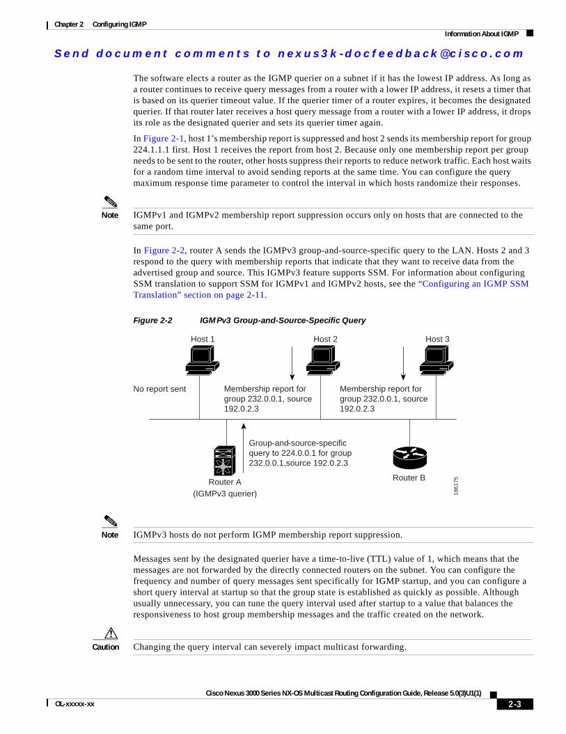
Figure 2-2 IGMPv3 Group-and-Source-Specific Query
Note IGMPv3 hosts do not perform IGMP membership report suppression.
Messages sent by the designated querier have a time-to-live (TTL) value of 1, which means that the messages are not forwarded by the directly connected routers on the subnet. You can configure the frequency and number of query messages sent specifically for IGMP startup, and you can configure a short query interval at startup so that the group state is established as quickly as possible. Although usually unnecessary, you can tune the query interval used after startup to a value that balances the responsiveness to host group membership messages and the traffic created on the network.
Caution Changing the query interval can severely impact multicast forwarding.
Router B
Host 1 Host 2 Host 3
1861
75
Membership report for group 232.0.0.1, source 192.0.2.3
Router A(IGMPv3 querier)
Group-and-source-specific query to 224.0.0.1 for group 232.0.0.1,source 192.0.2.3
No report sent Membership report for group 232.0.0.1, source 192.0.2.3
2-3Cisco Nexus 3000 Series NX-OS Multicast Routing Configuration Guide, Release 5.0(3)U1(1)
OL-xxxxx-xx
Se nd do cume nt c ommen ts t o nex us3k -d oc fee dba ck@c i sc o . co m
Chapter 2 Configuring IGMPLicensing Requirements for IGMP
When a multicast host leaves a group, a host that runs IGMPv2 or later sends an IGMP leave message. To check if this host is the last host to leave the group, the software sends an IGMP query message and starts a timer that you can configure called the last member query response interval. If no reports are received before the timer expires, the software removes the group state. The router continues to send multicast traffic for a group until its state is removed.
You can configure a robustness value to compensate for packet loss on a congested network. The robustness value is used by the IGMP software to determine the number of times to send messages.
Link local addresses in the range 224.0.0.0/24 are reserved by the Internet Assigned Numbers Authority (IANA). Network protocols on a local network segment use these addresses; routers do not forward these addresses because they have a TTL of 1. By default, the IGMP process sends membership reports only for nonlink local addresses, but you can configure the software to send reports for link local addresses.
For more information about configuring the IGMP parameters, see the “Configuring IGMP Interface Parameters” section on page 2-5.
Virtualization SupportCisco NX-OS suports virtual routing and forwarding (VRF). You can define multiple VRF instances. A VRF configured with IGMP supports the following IGMP features:
• IGMP is enabled or disabled on per interface
• IGMPv1, IGMPv2, and IGMPv3 provide router-side support
• IGMPv2 and IGMPv3 provide host-side support
• Supports configuration of IGMP querier parameters
• IGMP reporting is supported for link local multicast groups
• IGMP SSM-translation supports mapping of IGMPv2 groups to a set of sources
• Supports multicast trace-route (Mtrace) server functionality to process Mtrace requests
For information about configuring VRFs, see the Cisco Nexus 3000 Series NX-OS Unicast Routing Configuration Guide.
Licensing Requirements for IGMPThe following table shows the licensing requirements for this feature:
Product License Requirement
Cisco NX-OS IGMP requires no license. Any feature not included in a license package is bundled with the Cisco NX-OS system images and is provided at no extra charge to you. For a complete explanation of the Cisco NX-OS licensing scheme, see the Cisco NX-OS Licensing Guide.
Note Make sure the LAN Base Services license is installed on the switch to enable the Layer 3 interfaces.
2-4Cisco Nexus 3000 Series NX-OS Multicast Routing Configuration Guide, Release 5.0(3)U1(1)
OL-xxxxx-xx
Se nd do cume nt c ommen ts t o nex us3k -d oc fee dba ck@c i sc o . co m
Chapter 2 Configuring IGMPDefault Settings for IGMP
Default Settings for IGMPTable 2-1 lists the default settings for IGMP parameters.
Configuring IGMP ParametersYou can configure the IGMP global and interface parameters to affect the operation of the IGMP process.
This section includes the following topics:
• Configuring IGMP Interface Parameters, page 2-5
• Configuring an IGMP SSM Translation, page 2-11
• Configuring the Enforce Router Alert Option Check, page 2-12
Note If you are familiar with the Cisco IOS CLI, be aware that the Cisco NX-OS commands for this feature might differ from the Cisco IOS commands that you would use.
Configuring IGMP Interface ParametersYou can configure the optional IGMP interface parameters described in Table 2-2.
Table 2-1 Default IGMP Parameters
Parameters Default
IGMP version 2
Startup query interval 30 seconds
Startup query count 2
Robustness value 2
Querier timeout 255 seconds
Query timeout 255 seconds
Query max response time 10 seconds
Query interval 125 seconds
Last member query response interval 1 second
Last member query count 2
Group membership timeout 260 seconds
Report link local multicast groups Disabled
Enforce router alert Disabled
Immediate leave Disabled
2-5Cisco Nexus 3000 Series NX-OS Multicast Routing Configuration Guide, Release 5.0(3)U1(1)
OL-xxxxx-xx
Se nd do cume nt c ommen ts t o nex us3k -d oc fee dba ck@c i sc o . co m
Chapter 2 Configuring IGMPConfiguring IGMP Parameters
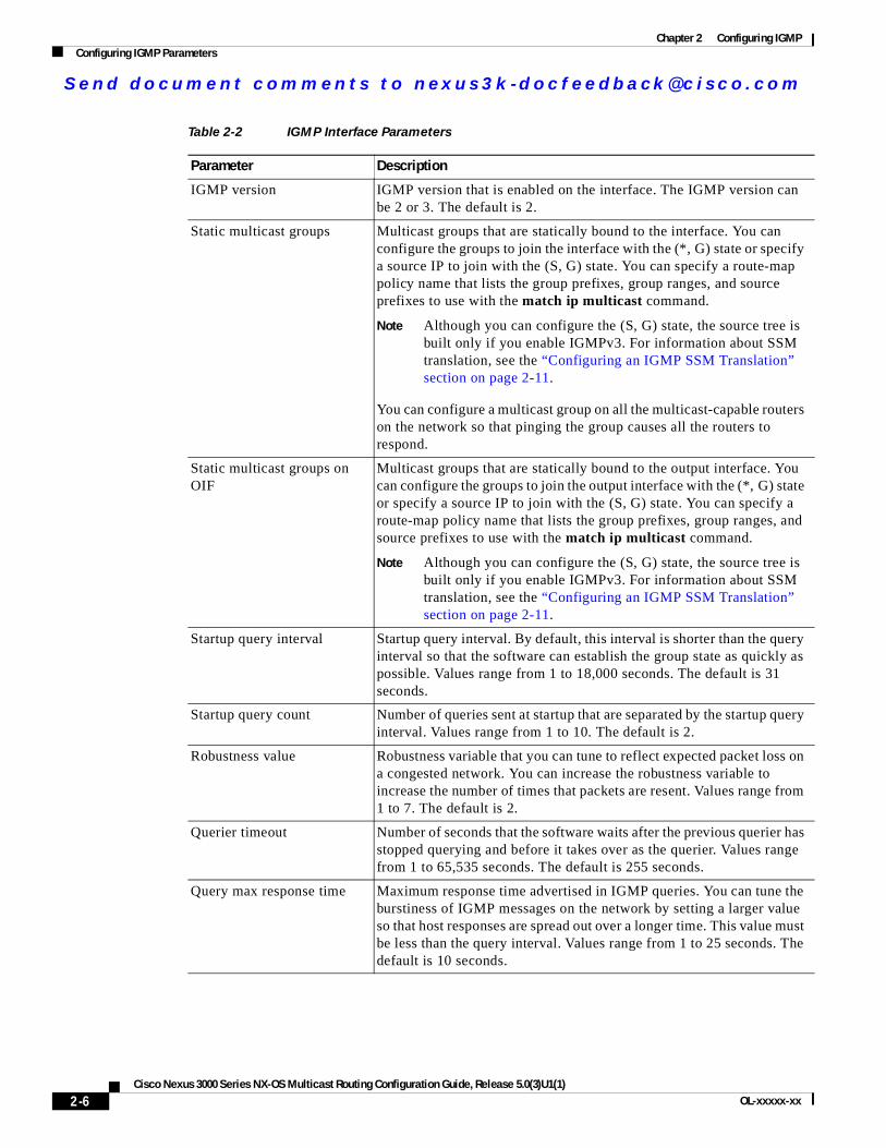
Table 2-2 IGMP Interface Parameters
Parameter Description
IGMP version IGMP version that is enabled on the interface. The IGMP version can be 2 or 3. The default is 2.
Static multicast groups Multicast groups that are statically bound to the interface. You can configure the groups to join the interface with the (*, G) state or specify a source IP to join with the (S, G) state. You can specify a route-map policy name that lists the group prefixes, group ranges, and source prefixes to use with the match ip multicast command.
Note Although you can configure the (S, G) state, the source tree is built only if you enable IGMPv3. For information about SSM translation, see the “Configuring an IGMP SSM Translation” section on page 2-11.
You can configure a multicast group on all the multicast-capable routers on the network so that pinging the group causes all the routers to respond.
Static multicast groups on OIF
Multicast groups that are statically bound to the output interface. You can configure the groups to join the output interface with the (*, G) state or specify a source IP to join with the (S, G) state. You can specify a route-map policy name that lists the group prefixes, group ranges, and source prefixes to use with the match ip multicast command.
Note Although you can configure the (S, G) state, the source tree is built only if you enable IGMPv3. For information about SSM translation, see the “Configuring an IGMP SSM Translation” section on page 2-11.
Startup query interval Startup query interval. By default, this interval is shorter than the query interval so that the software can establish the group state as quickly as possible. Values range from 1 to 18,000 seconds. The default is 31 seconds.
Startup query count Number of queries sent at startup that are separated by the startup query interval. Values range from 1 to 10. The default is 2.
Robustness value Robustness variable that you can tune to reflect expected packet loss on a congested network. You can increase the robustness variable to increase the number of times that packets are resent. Values range from 1 to 7. The default is 2.
Querier timeout Number of seconds that the software waits after the previous querier has stopped querying and before it takes over as the querier. Values range from 1 to 65,535 seconds. The default is 255 seconds.
Query max response time Maximum response time advertised in IGMP queries. You can tune the burstiness of IGMP messages on the network by setting a larger value so that host responses are spread out over a longer time. This value must be less than the query interval. Values range from 1 to 25 seconds. The default is 10 seconds.
2-6Cisco Nexus 3000 Series NX-OS Multicast Routing Configuration Guide, Release 5.0(3)U1(1)
OL-xxxxx-xx
Se nd do cume nt c ommen ts t o nex us3k -d oc fee dba ck@c i sc o . co m
Chapter 2 Configuring IGMPConfiguring IGMP Parameters
For information about configuring multicast route maps, see the “Configuring Route Maps to Control RP Information Distribution” section on page 3-27.
SUMMARY STEPS
1. configure terminal
Query interval Frequency at which the software sends IGMP host query messages. You can tune the number of IGMP messages on the network by setting a larger value so that the software sends IGMP queries less often. Values range from 1 to 18,000 seconds. The default is 125 seconds.
Last member query response interval
Interval in which the software sends a response to an IGMP query after receiving a host leave message from the last known active host on the subnet. If no reports are received in the interval, the group state is deleted. You can use this value to tune how quickly the software stops transmitting on the subnet. The software can detect the loss of the last member of a group or source more quickly when the values are smaller. Values range from 1 to 25 seconds. The default is 1 second.
Last member query count Number of times that the software sends an IGMP query, separated by the last member query response interval, in response to a host leave message from the last known active host on the subnet. Values range from 1 to 5. The default is 2.
Caution Setting this value to 1 means that a missed packet in either direction causes the software to remove the multicast state from the queried group or channel. The software may wait until the next query interval before the group is added again.
Group membership timeout Group membership interval that must pass before the router decides that no members of a group or source exist on the network. Values range from 3 to 65,535 seconds. The default is 260 seconds.
Report link local multicast groups
Option that enables sending reports for groups in 224.0.0.0/24. Link local addresses are used only by protocols on the local network. Reports are always sent for nonlink local groups. The default is disabled.
Report policy Access policy for IGMP reports that is based on a route-map policy1.
Access groups Option that configures a route-map policy1 to control the multicast groups that hosts on the subnet serviced by an interface can join.
Immediate leave Option that minimizes the leave latency of IGMPv2 group memberships on a given IGMP interface because the switch does not send group-specific queries. When immediate leave is enabled, the switch removes the group entry from the multicast routing table immediately upon receiving a leave message for the group. The default is disabled.
Note Use this command only when there is one receiver behind the interface for a given group.
1. To configure route-map policies, see the Cisco Nexus 3000 Series NX-OS Unicast Routing Configuration Guide.
Table 2-2 IGMP Interface Parameters (continued)
Parameter Description
2-7Cisco Nexus 3000 Series NX-OS Multicast Routing Configuration Guide, Release 5.0(3)U1(1)
OL-xxxxx-xx
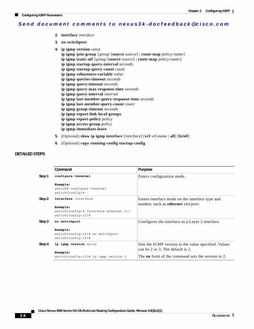
Se nd do cume nt c ommen ts t o nex us3k -d oc fee dba ck@c i sc o . co m
Chapter 2 Configuring IGMPConfiguring IGMP Parameters
2. interface interface
3. no switchport
4. ip igmp version valueip igmp join-group {group [source source] | route-map policy-name}ip igmp static-oif {group [source source] | route-map policy-name}ip igmp startup-query-interval secondsip igmp startup-query-count countip igmp robustness-variable valueip igmp querier-timeout secondsip igmp query-timeout secondsip igmp query-max-response-time secondsip igmp query-interval intervalip igmp last-member-query-response-time secondsip igmp last-member-query-count countip igmp group-timeout secondsip igmp report-link-local-groupsip igmp report-policy policyip igmp access-group policyip igmp immediate-leave
5. (Optional) show ip igmp interface [interface] [vrf vrf-name | all] [brief]
6. (Optional) copy running-config startup-config
DETAILED STEPS
Command Purpose
Step 1 configure terminal
Example:switch# configure terminalswitch(config)#
Enters configuration mode.
Step 2 interface interface
Example:switch(config)# interface ethernet 2/1switch(config-if)#
Enters interface mode on the interface type and number, such as ethernet slot/port.
Step 3 no switchport
Example:switch(config-if)# no switchportswitch(config-if)#
Configures the interface as a Layer 3 interface.
Step 4 ip igmp version value
Example:switch(config-if)# ip igmp version 3
Sets the IGMP version to the value specified. Values can be 2 or 3. The default is 2.
The no form of the command sets the version to 2.
2-8Cisco Nexus 3000 Series NX-OS Multicast Routing Configuration Guide, Release 5.0(3)U1(1)
OL-xxxxx-xx
Se nd do cume nt c ommen ts t o nex us3k -d oc fee dba ck@c i sc o . co m
Chapter 2 Configuring IGMPConfiguring IGMP Parameters
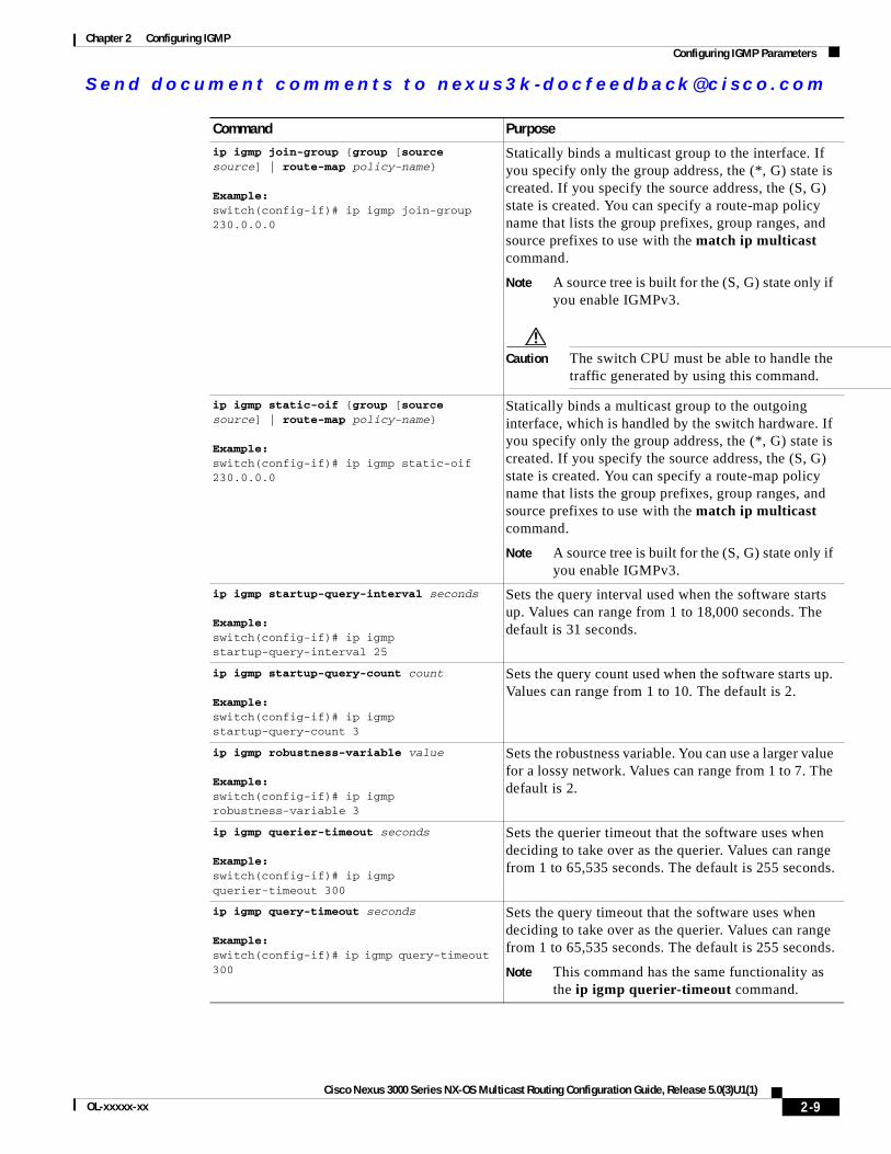
ip igmp join-group {group [source source] | route-map policy-name}
Example:switch(config-if)# ip igmp join-group 230.0.0.0
Statically binds a multicast group to the interface. If you specify only the group address, the (*, G) state is created. If you specify the source address, the (S, G) state is created. You can specify a route-map policy name that lists the group prefixes, group ranges, and source prefixes to use with the match ip multicast command.
Note A source tree is built for the (S, G) state only if you enable IGMPv3.
Caution The switch CPU must be able to handle the traffic generated by using this command.
ip igmp static-oif {group [source source] | route-map policy-name}
Example:switch(config-if)# ip igmp static-oif 230.0.0.0
Statically binds a multicast group to the outgoing interface, which is handled by the switch hardware. If you specify only the group address, the (*, G) state is created. If you specify the source address, the (S, G) state is created. You can specify a route-map policy name that lists the group prefixes, group ranges, and source prefixes to use with the match ip multicast command.
Note A source tree is built for the (S, G) state only if you enable IGMPv3.
ip igmp startup-query-interval seconds
Example:switch(config-if)# ip igmp startup-query-interval 25
Sets the query interval used when the software starts up. Values can range from 1 to 18,000 seconds. The default is 31 seconds.
ip igmp startup-query-count count
Example:switch(config-if)# ip igmp startup-query-count 3
Sets the query count used when the software starts up. Values can range from 1 to 10. The default is 2.
ip igmp robustness-variable value
Example:switch(config-if)# ip igmp robustness-variable 3
Sets the robustness variable. You can use a larger value for a lossy network. Values can range from 1 to 7. The default is 2.
ip igmp querier-timeout seconds
Example:switch(config-if)# ip igmp querier-timeout 300
Sets the querier timeout that the software uses when deciding to take over as the querier. Values can range from 1 to 65,535 seconds. The default is 255 seconds.
ip igmp query-timeout seconds
Example:switch(config-if)# ip igmp query-timeout 300
Sets the query timeout that the software uses when deciding to take over as the querier. Values can range from 1 to 65,535 seconds. The default is 255 seconds.
Note This command has the same functionality as the ip igmp querier-timeout command.
Command Purpose
2-9Cisco Nexus 3000 Series NX-OS Multicast Routing Configuration Guide, Release 5.0(3)U1(1)
OL-xxxxx-xx
Se nd do cume nt c ommen ts t o nex us3k -d oc fee dba ck@c i sc o . co m
Chapter 2 Configuring IGMPConfiguring IGMP Parameters
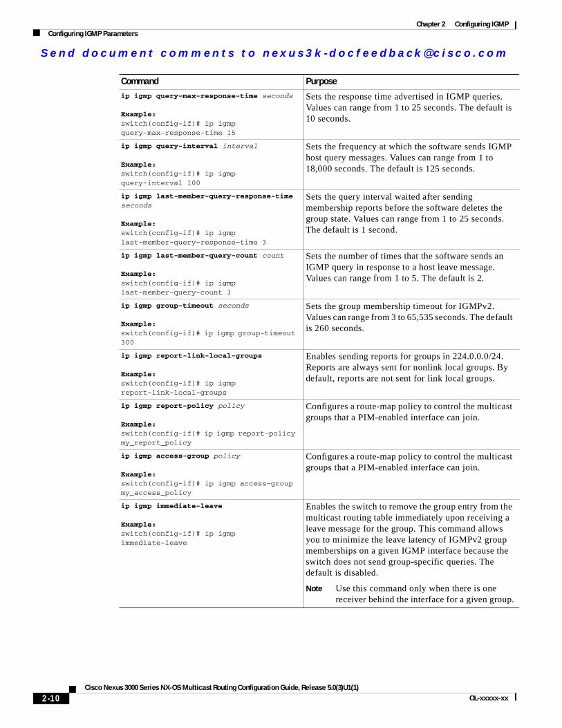
ip igmp query-max-response-time seconds
Example:switch(config-if)# ip igmp query-max-response-time 15
Sets the response time advertised in IGMP queries. Values can range from 1 to 25 seconds. The default is 10 seconds.
ip igmp query-interval interval
Example:switch(config-if)# ip igmp query-interval 100
Sets the frequency at which the software sends IGMP host query messages. Values can range from 1 to 18,000 seconds. The default is 125 seconds.
ip igmp last-member-query-response-time seconds
Example:switch(config-if)# ip igmp last-member-query-response-time 3
Sets the query interval waited after sending membership reports before the software deletes the group state. Values can range from 1 to 25 seconds. The default is 1 second.
ip igmp last-member-query-count count
Example:switch(config-if)# ip igmp last-member-query-count 3
Sets the number of times that the software sends an IGMP query in response to a host leave message. Values can range from 1 to 5. The default is 2.
ip igmp group-timeout seconds
Example:switch(config-if)# ip igmp group-timeout 300
Sets the group membership timeout for IGMPv2. Values can range from 3 to 65,535 seconds. The default is 260 seconds.
ip igmp report-link-local-groups
Example:switch(config-if)# ip igmp report-link-local-groups
Enables sending reports for groups in 224.0.0.0/24. Reports are always sent for nonlink local groups. By default, reports are not sent for link local groups.
ip igmp report-policy policy
Example:switch(config-if)# ip igmp report-policy my_report_policy
Configures a route-map policy to control the multicast groups that a PIM-enabled interface can join.
ip igmp access-group policy
Example:switch(config-if)# ip igmp access-group my_access_policy
Configures a route-map policy to control the multicast groups that a PIM-enabled interface can join.
ip igmp immediate-leave
Example:switch(config-if)# ip igmp immediate-leave
Enables the switch to remove the group entry from the multicast routing table immediately upon receiving a leave message for the group. This command allows you to minimize the leave latency of IGMPv2 group memberships on a given IGMP interface because the switch does not send group-specific queries. The default is disabled.
Note Use this command only when there is one receiver behind the interface for a given group.
Command Purpose
2-10Cisco Nexus 3000 Series NX-OS Multicast Routing Configuration Guide, Release 5.0(3)U1(1)
OL-xxxxx-xx
Se nd do cume nt c ommen ts t o nex us3k -d oc fee dba ck@c i sc o . co m
Chapter 2 Configuring IGMPConfiguring IGMP Parameters
Configuring an IGMP SSM TranslationYou can configure an SSM translation to provide SSM support when the router receives IGMPv1 or IGMPv2 membership reports. Only IGMPv3 provides the capability to specify group and source addresses in membership reports. By default, the group prefix range is 232.0.0.0/8. To modify the PIM SSM range, see the “Configuring SSM” section on page 3-24.
Table 2-3 lists the example SSM translations.
Table 2-4 shows the resulting MRIB routes that the IGMP process creates when it applies an SSM translation to the IGMP membership report. If more than one translation applies, the router creates the (S, G) state for each translation.
Note This feature is similar to SSM mapping found in some Cisco IOS software.
SUMMARY STEPS
1. configure terminal
2. ip igmp ssm-translate group-prefix source-addr
3. (Optional) show running-configuration igmp
Step 5 show ip igmp interface [interface] [vrf vrf-name | all] [brief]
Example:switch(config)# show ip igmp interface
(Optional) Displays IGMP information about the interface.
Step 6 copy running-config startup-config
Example:switch(config)# copy running-config startup-config
(Optional) Saves configuration changes.
Command Purpose
Table 2-3 Example SSM Translations
Group Prefix Source Address
232.0.0.0/8 10.1.1.1
232.0.0.0/8 10.2.2.2
232.1.0.0/16 10.3.3.3
232.1.1.0/24 10.4.4.4
Table 2-4 Example Result of Applying SSM Translations
IGMPv2 Membership Report Resulting MRIB Route
232.1.1.1 (10.4.4.4, 232.1.1.1)
232.2.2.2 (10.1.1.1, 232.2.2.2)(10.2.2.2, 232.2.2.2)
2-11Cisco Nexus 3000 Series NX-OS Multicast Routing Configuration Guide, Release 5.0(3)U1(1)
OL-xxxxx-xx
Se nd do cume nt c ommen ts t o nex us3k -d oc fee dba ck@c i sc o . co m
Chapter 2 Configuring IGMPConfiguring IGMP Parameters
4. (Optional) copy running-config startup-config
DETAILED STEPS
Configuring the Enforce Router Alert Option CheckYou can configure the enforce router alert option check for IGMPv2 and IGMPv3 packets.
SUMMARY STEPS
1. configure terminal
2. ip igmp enforce-router-alertno ip igmp enforce-router-alert
3. (Optional) show running-configuration igmp
4. (Optional) copy running-config startup-config
DETAILED STEPS
Command Purpose
Step 1 configure terminal
Example:switch# configure terminalswitch(config)#
Enters configuration mode.
Step 2 ip igmp ssm-translate group-prefix source-addr
Example:switch(config)# ip igmp ssm-translate 232.0.0.0/8 10.1.1.1
Configures the translation of IGMPv1 or IGMPv2 membership reports by the IGMP process to create the (S,G) state as if the router had received an IGMPv3 membership report.
Step 3 show running-configuration igmp
Example:switch(config)# show running-configuration igmp
(Optional) Shows the running-configuration information, including ssm-translate command lines.
Step 4 copy running-config startup-config
Example:switch(config)# copy running-config startup-config
(Optional) Saves configuration changes.
Command Purpose
Step 1 configure terminal
Example:switch# configure terminalswitch(config)#
Enters configuration mode.
2-12Cisco Nexus 3000 Series NX-OS Multicast Routing Configuration Guide, Release 5.0(3)U1(1)
OL-xxxxx-xx
Se nd do cume nt c ommen ts t o nex us3k -d oc fee dba ck@c i sc o . co m
Chapter 2 Configuring IGMPVerifying the IGMP Configuration
Verifying the IGMP ConfigurationTo display the IGMP configuration information, perform one of the following tasks:
For detailed information about the fields in the output from these commands, see the Cisco Nexus 3000 Series Command Reference,.
Step 2 ip igmp enforce-router-alert
Example:switch(config)# ip igmp enforce-router-alert
Enables the enforce router alert option check for IGMPv2 and IGMPv3 packets. By default, the enforce router alert option check is enabled.
no ip igmp enforce-router-alert
Example:switch(config)# no ip igmp enforce-router-alert
Disables the enforce router alert option check for IGMPv2 and IGMPv3 packets. By default, the enforce router alert option check is enabled.
Step 3 show running-configuration igmp
Example:switch(config)# show running-configuration igmp
(Optional) Shows the running-configuration information, including the enforce-router-alert command line.
Step 4 copy running-config startup-config
Example:switch(config)# copy running-config startup-config
(Optional) Saves configuration changes.
Command Purpose
Command Purpose
show ip igmp interface [interface] [vrf vrf-name | all] [brief]
Displays IGMP information about all interfaces or a selected interface, the default VRF, a selected VRF, or all VRFs.
show ip igmp groups [group | interface] [vrf vrf-name | all]
Displays the IGMP attached group membership for a group or interface, the default VRF, a selected VRF, or all VRFs.
show ip igmp route [group | interface] [vrf vrf-name | all]
Displays the IGMP attached group membership for a group or interface, the default VRF, a selected VRF, or all VRFs.
show ip igmp local-groups Displays the IGMP local group membership.
show running-configuration igmp Displays the IGMP running-configuration information.
show startup-configuration igmp Displays the IGMP startup-configuration information.
2-13Cisco Nexus 3000 Series NX-OS Multicast Routing Configuration Guide, Release 5.0(3)U1(1)
OL-xxxxx-xx

Se nd do cume nt c ommen ts t o nex us3k -d oc fee dba ck@c i sc o . co m
Chapter 2 Configuring IGMPConfiguration Examples for IGMP
Configuration Examples for IGMPThis example shows how to configure the IGMP parameters:
switch# configure terminalswitch(config)# ip igmp ssm-translate 232.0.0.0/8 10.1.1.1switch(config)# interface ethernet 2/1switch(config-if)# no switchportswitch(config-if)# ip igmp version 3switch(config-if)# ip igmp join-group 230.0.0.0switch(config-if)# ip igmp startup-query-interval 25switch(config-if)# ip igmp startup-query-count 3switch(config-if)# ip igmp robustness-variable 3switch(config-if)# ip igmp querier-timeout 300switch(config-if)# ip igmp query-timeout 300switch(config-if)# ip igmp query-max-response-time 15switch(config-if)# ip igmp query-interval 100switch(config-if)# ip igmp last-member-query-response-time 3switch(config-if)# ip igmp last-member-query-count 3switch(config-if)# ip igmp group-timeout 300switch(config-if)# ip igmp report-link-local-groupsswitch(config-if)# ip igmp report-policy my_report_policyswitch(config-if)# ip igmp access-group my_access_policy
This example shows how to configure a route map that accepts all multicast reports (joins):
switch(config)# route-map fooswitch(config-route-map)# exitswitch(config)# interface vlan 10switch(config-if)# no switchportswitch(config-if)# ip pim sparse-modeswitch(config-if)# ip igmp report-policy foo
This example shows how to configure a route map that denies all multicast reports (joins):
switch(config)# route-map foo deny 10switch(config-route-map)# exitswitch(config)# interface vlan 5switch(config-if)# ip pim sparse-modeswitch(config-if)# ip igmp report-policy foo
Where to Go NextYou can enable the following features that work with PIM and IGMP:
• Chapter 4, “Configuring IGMP Snooping”
• Chapter 5, “Configuring MSDP”
2-14Cisco Nexus 3000 Series NX-OS Multicast Routing Configuration Guide, Release 5.0(3)U1(1)
OL-xxxxx-xx
Se nd do cume nt c ommen ts t o nex us3k -d oc fee dba ck@c i sc o . co m
Chapter 2 Configuring IGMPFeature History for IGMP
Feature History for IGMPTable 2-5 lists the release history for this feature.
Table 2-5 Feature History for IGMP
Feature Name Releases Feature Information
IGMP 5.0(3)U1(1) This feature was introduced.
2-15Cisco Nexus 3000 Series NX-OS Multicast Routing Configuration Guide, Release 5.0(3)U1(1)
OL-xxxxx-xx

Se nd do cume nt c ommen ts t o nex us3k -d oc fee dba ck@c i sc o . co m
Chapter 2 Configuring IGMPFeature History for IGMP
2-16Cisco Nexus 3000 Series NX-OS Multicast Routing Configuration Guide, Release 5.0(3)U1(1)
OL-xxxxx-xx
Se nd do cume nt c ommen ts t o nex us3k -d oc fee dba ck@c i sc o . co m
Cisco Nexus 3000 Series NX-OS MulticaOL-xxxxx-xx
C H A P T E R 3
Configuring PIMThis chapter describes how to configure the Protocol Independent Multicast (PIM) features on Cisco NX-OS switches in your IPv4 networks.
This chapter includes the following sections:
• Information About PIM, page 3-1
• Licensing Requirements for PIM, page 3-8
• Guidelines and Limitations for PIM, page 3-8
• Default Settings, page 3-8
• Configuring PIM, page 3-9
• Verifying the PIM Configuration, page 3-32
• Displaying Statistics, page 3-33
• Configuration Examples for PIM, page 3-34
• Where to Go Next, page 3-37
• Additional References, page 3-37
• Feature History for PIM, page 3-38
Information About PIM PIM, which is used between multicast-capable routers, advertises group membership across a routing domain by constructing multicast distribution trees. PIM builds shared distribution trees on which packets from multiple sources are forwarded, as well as source distribution trees on which packets from a single source are forwarded. For more information about multicast, see the “Information About Multicast” section on page 1-1.
Cisco NX-OS supports PIM sparse mode for IPv4 networks (PIM). (In PIM sparse mode, multicast traffic is sent only to locations of the network that specifically request it.) You can configure PIM to run simultaneously on a router. You can use PIM global parameters to configure rendezvous points (RPs), message packet filtering, and statistics. You can use PIM interface parameters to enable multicast, identify PIM borders, set the PIM hello message interval, and set the designated router (DR) priority. For more information, see the “Configuring PIM Sparse Mode” section on page 3-11.
Note Cisco NX-OS does not support PIM dense mode.
3-1st Routing Configuration Guide, Release 5.0(3)U1(1)
Se nd do cume nt c ommen ts t o nex us3k -d oc fee dba ck@c i sc o . co m
Chapter 3 Configuring PIMInformation About PIM
In Cisco NX-OS, multicast is enabled only after you enable the PIM feature on each router and then enable PIM sparse mode on each interface that you want to participate in multicast. You can configure PIM for an IPv4 network. In an IPv4 network, if you have not already enabled IGMP on the router, PIM enables it automatically. For information about configuring IGMP, see Chapter 2, “Configuring IGMP”.
You use the PIM global configuration parameters to configure the range of multicast group addresses to be handled by each of the two distribution modes:
• Any Source Multicast (ASM) provides discovery of multicast sources. It builds a shared tree between sources and receivers of a multicast group and supports switching over to a source tree when a new receiver is added to a group. ASM mode requires that you configure an RP.
• Single Source Multicast (SSM) builds a source tree originating at the designated router on the LAN segment that receives a request to join a multicast source. SSM mode does not require you to configure RPs. Source discovery must be accomplished through other means.
You can combine the modes to cover different ranges of group addresses. For more information, see the “Configuring PIM” section on page 3-9.
For more information about PIM sparse mode and shared distribution trees used by the ASM mode, see RFC 4601.
For more information about PIM SSM mode, see RFC 3569.
Note Multicast equal-cost multipathing (ECMP) is on by default in the Cisco NX-OS for the Cisco Nexus 3000 Series switches; you cannot turn ECMP off. If multiple paths exist for a prefix, PIM selects the path with the lowest administrative distance in the routing table. Cisco NX-OS supports up to 16 paths to a destination.
This section includes the following topics:
• Hello Messages, page 3-2
• Join-Prune Messages, page 3-3
• State Refreshes, page 3-3
• Rendezvous Points, page 3-4
• PIM Register Messages, page 3-7
• Designated Routers, page 3-7
• Administratively Scoped IP Multicast, page 3-7
Hello MessagesThe PIM process begins when the router establishes PIM neighbor adjacencies by sending PIM hello messages to the multicast address 224.0.0.13. Hello messages are sent periodically at the interval of 30 seconds. When all neighbors have replied, then the PIM software chooses the router with the highest priority in each LAN segment as the designated router (DR). The DR priority is based on a DR priority value in the PIM hello message. If the DR priority value is not supplied by all routers, or the priorities match, the highest IP address is used to elect the DR.
Caution If you change the PIM hello interval to a lower value, we recommend that you ensure it is appropriate for your network environment.
3-2Cisco Nexus 3000 Series NX-OS Multicast Routing Configuration Guide, Release 5.0(3)U1(1)
OL-xxxxx-xx
Se nd do cume nt c ommen ts t o nex us3k -d oc fee dba ck@c i sc o . co m
Chapter 3 Configuring PIMInformation About PIM
The hello message also contains a hold-time value, which is typically 3.5 times the hello interval. If this hold time expires without a subsequent hello message from its neighbor, the switch detects a PIM failure on that link.
For added security, you can configure an MD5 hash value that the PIM software uses to authenticate PIM hello messages with PIM neighbors.
Note If PIM is disabled on the switch, the IGMP snooping software processes the PIM hello messages.
For information about configuring hello message authentication, see the “Configuring PIM Sparse Mode” section on page 3-11.
Join-Prune MessagesWhen the DR receives an IGMP membership report message from a receiver for a new group or source, the DR creates a tree to connect the receiver to the source by sending a PIM join message out the interface toward the rendezvous point (ASM mode) or source (SSM mode).The rendezvous point (RP) is the root of a shared tree, which is used by all sources and hosts in the PIM domain in the ASM mode. SSM does not use an RP but builds a shortest path tree (SPT) that is the lowest cost path between the source and the receiver.
When the DR determines that the last host has left a group or source, it sends a PIM prune message to remove the path from the distribution tree.
The routers forward the join or prune action hop by hop up the multicast distribution tree to create (join) or tear down (prune) the path.
Note In this publication, the terms “PIM join message” and “PIM prune message” are used to simplify the action taken when referring to the PIM join-prune message with only a join or prune action.
Join-prune messages are sent as quickly as possible by the software. You can filter the join-prune messages by defining a routing policy. For information about configuring the join-prune message policy, see the “Configuring PIM Sparse Mode” section on page 3-11.
You can prebuild the SPT for all known (S,G) in the routing table by triggering PIM joins upstream. To prebuild the SPT for all known (S,G)s in the routing table by triggering PIM joins upstream, even in the absence of any receivers, use the ip pim pre-build-spt command. By default, PIM (S,G) joins are triggered upstream only if the OIF-list for the (S,G) is not empty.
State RefreshesPIM requires that multicast entries are refreshed within a 3.5-minute timeout interval. The state refresh ensures that traffic is delivered only to active listeners, and it keeps routers from using unnecessary resources.
To maintain the PIM state, the last-hop DR sends join-prune messages once per minute. State creation applies to both (*, G) and (S, G) states as follows:
• (*, G) state creation example—An IGMP (*, G) report triggers the DR to send a (*, G) PIM join message toward the RP.
3-3Cisco Nexus 3000 Series NX-OS Multicast Routing Configuration Guide, Release 5.0(3)U1(1)
OL-xxxxx-xx
Se nd do cume nt c ommen ts t o nex us3k -d oc fee dba ck@c i sc o . co m
Chapter 3 Configuring PIMInformation About PIM
• (S, G) state creation example—An IGMP (S, G) report triggers the DR to send an (S, G) PIM join message toward the source.
If the state is not refreshed, the PIM software tears down the distribution tree by removing the forwarding paths in the multicast outgoing interface list of the upstream routers.
Rendezvous PointsA rendezvous point (RP) is a router that you select in a multicast network domain that acts as a shared root for a multicast shared tree. You can configure as many RPs as you like, and you can configure them to cover different group ranges.
This section includes the following topics:
• Static RP, page 3-4
• BSRs, page 3-4
• Auto-RP, page 3-5
• Anycast-RP, page 3-6
Static RP
You can statically configure an RP for a multicast group range. You must configure the address of the RP on every router in the domain.
You can define static RPs for the following reasons:
• To configure routers with the Anycast-RP address
• To manually configure an RP on a switch
For information about configuring static RPs, see the “Configuring Static RPs” section on page 3-15.
BSRs
The bootstrap router (BSR) ensures that all routers in the PIM domain have the same RP cache as the BSR. You can configure the BSR to help you select an RP set from BSR candidate RPs. The function of the BSR is to broadcast the RP set to all routers in the domain. You select one or more candidate BSRs to manage the RPs in the domain. Only one candidate BSR is elected as the BSR for the domain.
Caution Do not configure both Auto-RP and BSR protocols in the same network.
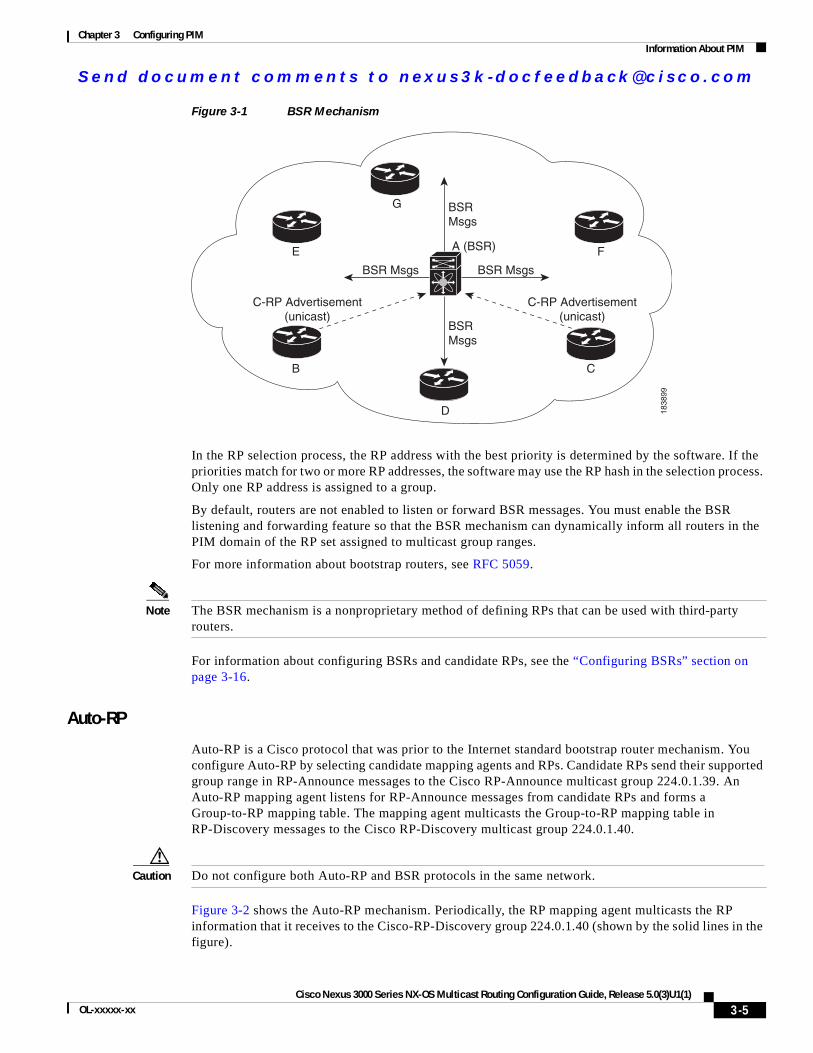
Figure 3-1 shows where the BSR mechanism. router A, the software-elected BSR, sends BSR messages out all enabled interfaces (shown by the solid lines in the figure). The messages, which contain the RP set, are flooded hop by hop to all routers in the network. Routers B and C are candidate RPs that send their candidate-RP advertisements directly to the elected BSR (shown by the dashed lines in the figure).
The elected BSR receives candidate-RP messages from all the candidate RPs in the domain. The bootstrap message sent by the BSR includes information about all of the candidate RPs. Each router uses a common algorithm to select the same RP address for a given multicast group.
3-4Cisco Nexus 3000 Series NX-OS Multicast Routing Configuration Guide, Release 5.0(3)U1(1)
OL-xxxxx-xx
Se nd do cume nt c ommen ts t o nex us3k -d oc fee dba ck@c i sc o . co m
Chapter 3 Configuring PIMInformation About PIM
Figure 3-1 BSR Mechanism
In the RP selection process, the RP address with the best priority is determined by the software. If the priorities match for two or more RP addresses, the software may use the RP hash in the selection process. Only one RP address is assigned to a group.
By default, routers are not enabled to listen or forward BSR messages. You must enable the BSR listening and forwarding feature so that the BSR mechanism can dynamically inform all routers in the PIM domain of the RP set assigned to multicast group ranges.
For more information about bootstrap routers, see RFC 5059.
Note The BSR mechanism is a nonproprietary method of defining RPs that can be used with third-party routers.
For information about configuring BSRs and candidate RPs, see the “Configuring BSRs” section on page 3-16.
Auto-RP
Auto-RP is a Cisco protocol that was prior to the Internet standard bootstrap router mechanism. You configure Auto-RP by selecting candidate mapping agents and RPs. Candidate RPs send their supported group range in RP-Announce messages to the Cisco RP-Announce multicast group 224.0.1.39. An Auto-RP mapping agent listens for RP-Announce messages from candidate RPs and forms a Group-to-RP mapping table. The mapping agent multicasts the Group-to-RP mapping table in RP-Discovery messages to the Cisco RP-Discovery multicast group 224.0.1.40.
Caution Do not configure both Auto-RP and BSR protocols in the same network.
Figure 3-2 shows the Auto-RP mechanism. Periodically, the RP mapping agent multicasts the RP information that it receives to the Cisco-RP-Discovery group 224.0.1.40 (shown by the solid lines in the figure).
18
38
99
G
E
B
F
C
D
BSR
Msgs
BSR
Msgs
BSR MsgsBSR Msgs
A (BSR)
C-RP Advertisement
(unicast)
C-RP Advertisement
(unicast)
3-5Cisco Nexus 3000 Series NX-OS Multicast Routing Configuration Guide, Release 5.0(3)U1(1)
OL-xxxxx-xx
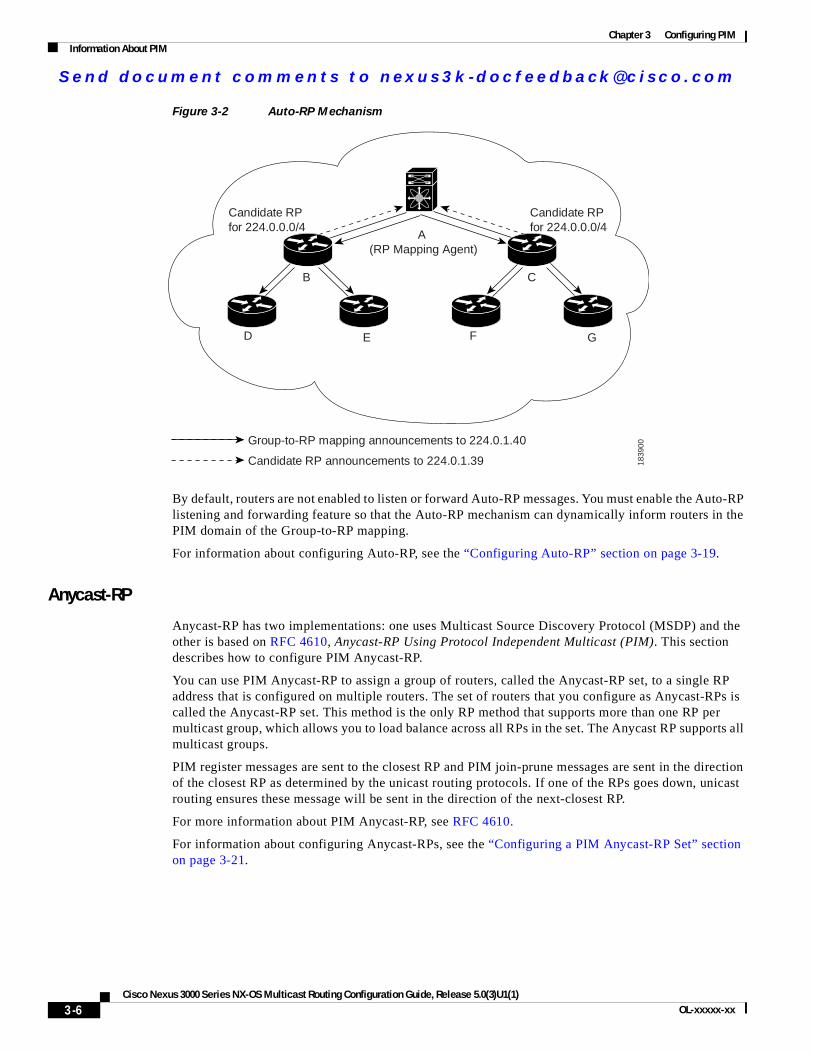
Se nd do cume nt c ommen ts t o nex us3k -d oc fee dba ck@c i sc o . co m
Chapter 3 Configuring PIMInformation About PIM
Figure 3-2 Auto-RP Mechanism
By default, routers are not enabled to listen or forward Auto-RP messages. You must enable the Auto-RP listening and forwarding feature so that the Auto-RP mechanism can dynamically inform routers in the PIM domain of the Group-to-RP mapping.
For information about configuring Auto-RP, see the “Configuring Auto-RP” section on page 3-19.
Anycast-RP
Anycast-RP has two implementations: one uses Multicast Source Discovery Protocol (MSDP) and the other is based on RFC 4610, Anycast-RP Using Protocol Independent Multicast (PIM). This section describes how to configure PIM Anycast-RP.
You can use PIM Anycast-RP to assign a group of routers, called the Anycast-RP set, to a single RP address that is configured on multiple routers. The set of routers that you configure as Anycast-RPs is called the Anycast-RP set. This method is the only RP method that supports more than one RP per multicast group, which allows you to load balance across all RPs in the set. The Anycast RP supports all multicast groups.
PIM register messages are sent to the closest RP and PIM join-prune messages are sent in the direction of the closest RP as determined by the unicast routing protocols. If one of the RPs goes down, unicast routing ensures these message will be sent in the direction of the next-closest RP.
For more information about PIM Anycast-RP, see RFC 4610.
For information about configuring Anycast-RPs, see the “Configuring a PIM Anycast-RP Set” section on page 3-21.
1839
00
B
ED
C
A(RP Mapping Agent)
GF
Candidate RP announcements to 224.0.1.39
Group-to-RP mapping announcements to 224.0.1.40
Candidate RP for 224.0.0.0/4
Candidate RP for 224.0.0.0/4
3-6Cisco Nexus 3000 Series NX-OS Multicast Routing Configuration Guide, Release 5.0(3)U1(1)
OL-xxxxx-xx
Se nd do cume nt c ommen ts t o nex us3k -d oc fee dba ck@c i sc o . co m
Chapter 3 Configuring PIMInformation About PIM
PIM Register MessagesPIM register messages are unicast to the RP by designated routers (DRs) that are directly connected to multicast sources. The PIM register message has the following functions:
• To notify the RP that a source is actively sending to a multicast group.
• To deliver multicast packets sent by the source to the RP for delivery down the shared tree.
The DR continues to send PIM register messages to the RP until it receives a Register-Stop message from the RP. The RP sends a Register-Stop message in either of the following cases:
• The RP has no receivers for the multicast group being transmitted.
• The RP has joined the SPT to the source but has not started receiving traffic from the source.
Note In Cisco NX-OS, PIM register messages are rate limited to avoid overwhelming the RP.
You can filter PIM register messages by defining a routing policy. For information about configuring the PIM register message policy, see the “Configuring Shared Trees Only for ASM” section on page 3-23.
Designated RoutersIn PIM ASM and SSM modes, the software chooses a designated router (DR) from the routers on each network segment. The DR is responsible for forwarding multicast data for specified groups and sources on that segment.
The DR for each LAN segment is determined as described in the “Hello Messages” section on page 3-2.
In ASM mode, the DR is responsible for unicasting PIM register packets to the RP. When a DR receives an IGMP membership report from a directly connected receiver, the shortest path is formed to the RP, which may or may not go through the DR. The result is a shared tree that connects all sources transmitting on the same multicast group to all receivers of that group.
In SSM mode, the DR triggers (*, G) or (S, G) PIM join messages toward the source. The path from the receiver to the source is determined hop by hop. The source must be known to the receiver or the DR.
For information about configuring the DR priority, see the “Configuring PIM Sparse Mode” section on page 3-11.
Administratively Scoped IP MulticastThe administratively scoped IP multicast method allows you to set boundaries on the delivery of multicast data. For more information, see RFC 2365.
You can configure an interface as a PIM boundary so that PIM messages are not sent out that interface. For information about configuring the domain border parameter, see the “Configuring PIM Sparse Mode” section on page 3-11.
You can use the Auto-RP scope parameter to set a time-to-live (TTL) value. For more information, see the “Configuring Shared Trees Only for ASM” section on page 3-23.
3-7Cisco Nexus 3000 Series NX-OS Multicast Routing Configuration Guide, Release 5.0(3)U1(1)
OL-xxxxx-xx
Se nd do cume nt c ommen ts t o nex us3k -d oc fee dba ck@c i sc o . co m
Chapter 3 Configuring PIMLicensing Requirements for PIM
Virtualization SupportYou can define multiple virtual routing and forwarding (VRF) instances. For each VRF, independent multicast system resources are maintained, including the MRIB.
You can use the PIM show commands with a VRF argument to provide a context for the information displayed. The default VRF is used if no VRF argument is supplied.
For information about configuring VRFs, see the Cisco Nexus 3000 Series NX-OS Unicast Routing Configuration Guide.
Licensing Requirements for PIMThe following table shows the licensing requirements for this feature:
Guidelines and Limitations for PIMPIM has the following guidelines and limitations:
• Cisco NX-OS PIM does not interoperate with any version of PIM dense mode or PIM sparse mode version 1.
• Do not configure both Auto-RP and BSR protocols in the same network.
• Configure candidate RP intervals to a minimum of 15 seconds.
• If a switch is configured with a BSR policy that should prevent it from being elected as the BSR, the switch ignores the policy. This behavior results in the following undesirable conditions:
– If a switch receives a BSM that is permitted by the policy, the switch, which incorrectly elected itself as the BSR, drops that BSM so that routers downstream fail to receive it. Downstream switches correctly filter the BSM from the incorrect BSR so that they do not receive RP information.
– A BSM received by a BSR from a different switch sends a new BSM but ensures that downstream switches do not receive the correct BSM.
Default SettingsTable 3-1 lists the default settings for PIM parameters.
Product License Requirement
Cisco NX-OS PIM require a LAN Base Services license. For a complete explanation of the Cisco NX-OS licensing scheme and how to obtain and apply licenses, see the Cisco NX-OS Licensing Guide.
Table 3-1 Default PIM Parameters
Parameters Default
Use shared trees only Disabled
Flush routes on restart Disabled
3-8Cisco Nexus 3000 Series NX-OS Multicast Routing Configuration Guide, Release 5.0(3)U1(1)
OL-xxxxx-xx
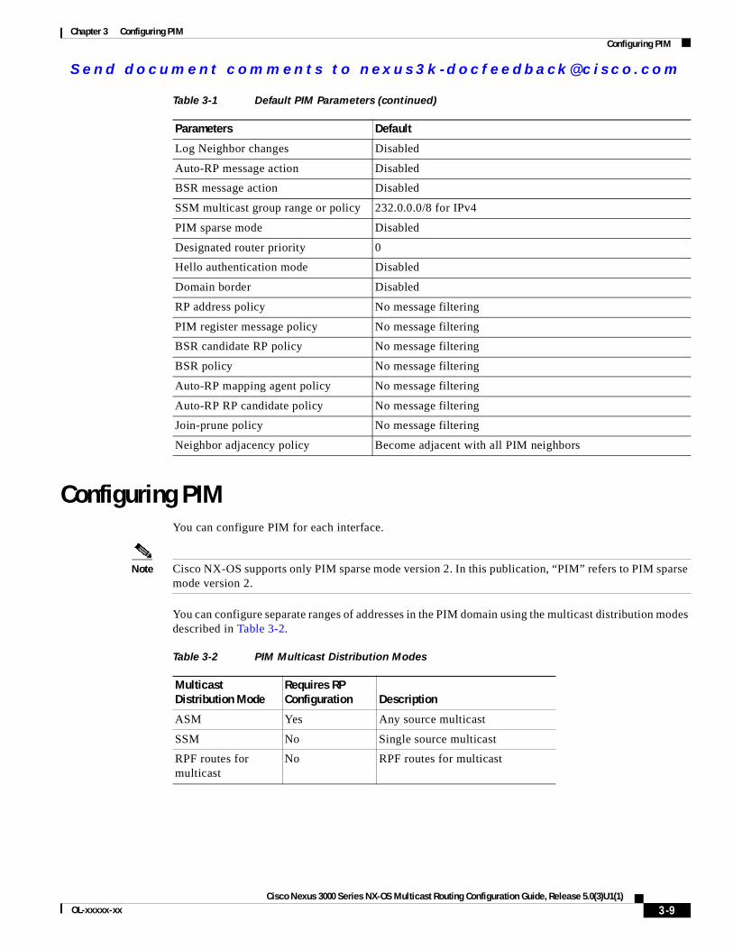
Se nd do cume nt c ommen ts t o nex us3k -d oc fee dba ck@c i sc o . co m
Chapter 3 Configuring PIMConfiguring PIM
Configuring PIMYou can configure PIM for each interface.
Note Cisco NX-OS supports only PIM sparse mode version 2. In this publication, “PIM” refers to PIM sparse mode version 2.
You can configure separate ranges of addresses in the PIM domain using the multicast distribution modes described in Table 3-2.
Log Neighbor changes Disabled
Auto-RP message action Disabled
BSR message action Disabled
SSM multicast group range or policy 232.0.0.0/8 for IPv4
PIM sparse mode Disabled
Designated router priority 0
Hello authentication mode Disabled
Domain border Disabled
RP address policy No message filtering
PIM register message policy No message filtering
BSR candidate RP policy No message filtering
BSR policy No message filtering
Auto-RP mapping agent policy No message filtering
Auto-RP RP candidate policy No message filtering
Join-prune policy No message filtering
Neighbor adjacency policy Become adjacent with all PIM neighbors
Table 3-1 Default PIM Parameters (continued)
Parameters Default
Table 3-2 PIM Multicast Distribution Modes
Multicast Distribution Mode
Requires RP Configuration Description
ASM Yes Any source multicast
SSM No Single source multicast
RPF routes for multicast
No RPF routes for multicast
3-9Cisco Nexus 3000 Series NX-OS Multicast Routing Configuration Guide, Release 5.0(3)U1(1)
OL-xxxxx-xx
Se nd do cume nt c ommen ts t o nex us3k -d oc fee dba ck@c i sc o . co m
Chapter 3 Configuring PIMConfiguring PIM
To configure PIM, follow these steps:
Step 1 From the multicast distribution modes described in Table 3-2, select the range of multicast groups that you want to configure in each mode.
Step 2 Enable the PIM features. See the “Enabling the PIM Features” section on page 3-10.
Step 3 Configure PIM sparse mode on each interface that you want to participate in a PIM domain. See the “Configuring PIM Sparse Mode” section on page 3-11.
Step 4 Follow the configuration steps for the multicast distribution modes that you selected in Step 1 as follows:
• For ASM mode, see the “Configuring ASM” section on page 3-15.
• For SSM mode, see the “Configuring SSM” section on page 3-24.
• For RPF routes for multicast, see the “Configuring RPF Routes for Multicast” section on page 3-26.
Step 5 Configure message filtering. See the “Configuring Message Filtering” section on page 3-28.
This section includes the following topics:
• Enabling the PIM Features, page 3-10
• Configuring PIM Sparse Mode, page 3-11
• Configuring ASM, page 3-15
• Configuring SSM, page 3-24
• Configuring RPF Routes for Multicast, page 3-26
• Configuring Route Maps to Control RP Information Distribution, page 3-27
• Configuring Message Filtering, page 3-28
Note If you are familiar with the Cisco IOS CLI, be aware that the Cisco NX-OS commands for this feature might differ from the Cisco IOS commands that you would use.
Enabling the PIM FeaturesBefore you can access the PIM commands, you must enable the PIM feature.
BEFORE YOU BEGIN
Ensure that you have installed the LAN Base Services license.
SUMMARY STEPS
1. configure terminal
2. feature pim
3. (Optional) show running-configuration pim
4. (Optional) copy running-config startup-config
3-10Cisco Nexus 3000 Series NX-OS Multicast Routing Configuration Guide, Release 5.0(3)U1(1)
OL-xxxxx-xx
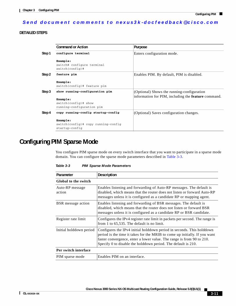
Se nd do cume nt c ommen ts t o nex us3k -d oc fee dba ck@c i sc o . co m
Chapter 3 Configuring PIMConfiguring PIM
DETAILED STEPS
Configuring PIM Sparse ModeYou configure PIM sparse mode on every switch interface that you want to participate in a sparse mode domain. You can configure the sparse mode parameters described in Table 3-3.
Command or Action Purpose
Step 1 configure terminal
Example:switch# configure terminalswitch(config)#
Enters configuration mode.
Step 2 feature pim
Example:switch(config)# feature pim
Enables PIM. By default, PIM is disabled.
Step 3 show running-configuration pim
Example:switch(config)# show running-configuration pim
(Optional) Shows the running-configuration information for PIM, including the feature command.
Step 4 copy running-config startup-config
Example:switch(config)# copy running-config startup-config
(Optional) Saves configuration changes.
Table 3-3 PIM Sparse Mode Parameters
Parameter Description
Global to the switch
Auto-RP message action
Enables listening and forwarding of Auto-RP messages. The default is disabled, which means that the router does not listen or forward Auto-RP messages unless it is configured as a candidate RP or mapping agent.
BSR message action Enables listening and forwarding of BSR messages. The default is disabled, which means that the router does not listen or forward BSR messages unless it is configured as a candidate RP or BSR candidate.
Register rate limit Configures the IPv4 register rate limit in packets per second. The range is from 1 to 65,535. The default is no limit.
Initial holddown period Configures the IPv4 initial holddown period in seconds. This holddown period is the time it takes for the MRIB to come up initially. If you want faster convergence, enter a lower value. The range is from 90 to 210. Specify 0 to disable the holddown period. The default is 210.
Per switch interface
PIM sparse mode Enables PIM on an interface.
3-11Cisco Nexus 3000 Series NX-OS Multicast Routing Configuration Guide, Release 5.0(3)U1(1)
OL-xxxxx-xx

Se nd do cume nt c ommen ts t o nex us3k -d oc fee dba ck@c i sc o . co m
Chapter 3 Configuring PIMConfiguring PIM
For information about configuring multicast route maps, see the “Configuring Route Maps to Control RP Information Distribution” section on page 3-27.
Note To configure the join-prune policy, see the “Configuring Message Filtering” section on page 3-28.
BEFORE YOU BEGIN
Ensure that you have installed the LAN Base Services license and enabled PIM.
Designated router priority
Sets the designated router (DR) priority that is advertised in PIM hello messages on this interface. On a multi-access network with multiple PIM-enabled routers, the router with the highest DR priority is elected as the DR router. If the priorities match, the software elects the DR with the highest IP address. The DR originates PIM register messages for the directly connected multicast sources and sends PIM join messages toward the rendezvous point (RP) for directly connected receivers. Values range from 1 to 4294967295. The default is 1.
Hello authentication mode
Enables an MD5 hash authentication key, or password, in PIM hello messages on the interface so that directly connected neighbors can authenticate each other. The PIM hello messages are IPsec encoded using the Authentication Header (AH) option. You can enter an unencrypted (cleartext) key, or one of these values followed by a space and the MD5 authentication key:
• 0—Specifies an unencrypted (cleartext) key
• 3—Specifies a 3-DES encrypted key
• 7—Specifies a Cisco Type 7 encrypted key
The authentication key can be up to 16 characters. The default is disabled.
Hello interval Configures the interval at which hello messages are sent in milliseconds. The range is from 1 to 4294967295. The default is 30000.
Domain border Enables the interface to be on the border of a PIM domain so that no bootstrap, candidate-RP, or Auto-RP messages are sent or received on the interface. The default is disabled.
Neighbor policy Configures which PIM neighbors to become adjacent to based on a route-map policy1 where you can specify IP addresses to become adjacent to with the match ip address command. If the policy name does not exist, or no IP addresses are configured in a policy, then adjacency is established with all neighbors. The default is to become adjacent with all PIM neighbors.
Note We recommend that you should configure this feature only if you are an experienced network administrator.
1. To configure route-map policies, see the Cisco Nexus 3000 Series NX-OS Unicast Routing Configuration Guide.
Table 3-3 PIM Sparse Mode Parameters (continued)
Parameter Description
3-12Cisco Nexus 3000 Series NX-OS Multicast Routing Configuration Guide, Release 5.0(3)U1(1)
OL-xxxxx-xx
Se nd do cume nt c ommen ts t o nex us3k -d oc fee dba ck@c i sc o . co m
Chapter 3 Configuring PIMConfiguring PIM
SUMMARY STEPS
1. configure terminal
2. (Optional) ip pim auto-rp {listen [forward] | forward [listen]}
3. (Optional) ip pim bsr {listen [forward] | forward [listen]}
4. (Optional) show ip pim rp [ip-prefix] [vrf vrf-name | all]
5. (Optional) ip pim register-rate-limit rate
6. (Optional) [ip | ipv4] routing multicast holddown holddown-period
7. (Optional) show running-configuration pim
8. interface interface
9. no switchport
10. ip pim sparse-mode
11. (Optional) ip pim dr-priority priority
12. (Optional) ip pim hello-authentication ah-md5 auth-key
13. (Optional) ip pim hello-interval interval
14. (Optional) ip pim border
15. (Optional) ip pim neighbor-policy policy-name
16. (Optional) show ip pim interface [interface | brief] [vrf vrf-name | all]
17. (Optional) copy running-config startup-config
DETAILED STEPS
Command Purpose
Step 1 configure terminal
Example:switch# configure terminalswitch(config)#
Enters configuration mode.
Step 2 ip pim auto-rp {listen [forward] | forward [listen]}
Example:switch(config)# ip pim auto-rp listen
(Optional) Enables listening or forwarding of Auto-RP messages. The default is disabled, which means that the software does not listen to or forward Auto-RP messages.
Step 3 ip pim bsr {listen [forward] | forward [listen]}
Example:switch(config)# ip pim bsr forward
(Optional) Enables listening or forwarding of BSR messages. The default is disabled, which means that the software does not listen or forward BSR messages.
Step 4 show ip pim rp [ip-prefix] [vrf vrf-name | all]
Example:switch(config)# show ip pim rp
(Optional) Displays PIM RP information, including Auto-RP and BSR listen and forward states.
3-13Cisco Nexus 3000 Series NX-OS Multicast Routing Configuration Guide, Release 5.0(3)U1(1)
OL-xxxxx-xx
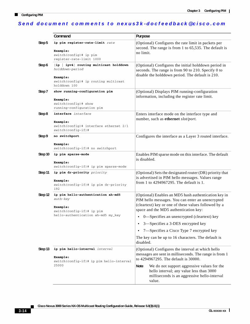
Se nd do cume nt c ommen ts t o nex us3k -d oc fee dba ck@c i sc o . co m
Chapter 3 Configuring PIMConfiguring PIM
Step 5 ip pim register-rate-limit rate
Example:switch(config)# ip pim register-rate-limit 1000
(Optional) Configures the rate limit in packets per second. The range is from 1 to 65,535. The default is no limit.
Step 6 [ip | ipv4] routing multicast holddown holddown-period
Example:switch(config)# ip routing multicast holddown 100
(Optional) Configures the initial holddown period in seconds. The range is from 90 to 210. Specify 0 to disable the holddown period. The default is 210.
Step 7 show running-configuration pim
Example:switch(config)# show running-configuration pim
(Optional) Displays PIM running-configuration information, including the register rate limit.
Step 8 interface interface
Example:switch(config)# interface ethernet 2/1switch(config-if)#
Enters interface mode on the interface type and number, such as ethernet slot/port.
Step 9 no switchport
Example:switch(config-if)# no switchport
Configures the interface as a Layer 3 routed interface.
Step 10 ip pim sparse-mode
Example:switch(config-if)# ip pim sparse-mode
Enables PIM sparse mode on this interface. The default is disabled.
Step 11 ip pim dr-priority priority
Example:switch(config-if)# ip pim dr-priority 192
(Optional) Sets the designated router (DR) priority that is advertised in PIM hello messages. Values range from 1 to 4294967295. The default is 1.
Step 12 ip pim hello-authentication ah-md5 auth-key
Example:switch(config-if)# ip pim hello-authentication ah-md5 my_key
(Optional) Enables an MD5 hash authentication key in PIM hello messages. You can enter an unencrypted (cleartext) key or one of these values followed by a space and the MD5 authentication key:
• 0—Specifies an unencrypted (cleartext) key
• 3—Specifies a 3-DES encrypted key
• 7—Specifies a Cisco Type 7 encrypted key
The key can be up to 16 characters. The default is disabled.
Step 13 ip pim hello-interval interval
Example:switch(config-if)# ip pim hello-interval 25000
(Optional) Configures the interval at which hello messages are sent in milliseconds. The range is from 1 to 4294967295. The default is 30000.
Note We do not support aggressive values for the hello interval; any value less than 3000 milliseconds is an aggressive hello-interval value.
Command Purpose
3-14Cisco Nexus 3000 Series NX-OS Multicast Routing Configuration Guide, Release 5.0(3)U1(1)
OL-xxxxx-xx
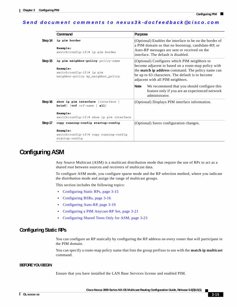
Se nd do cume nt c ommen ts t o nex us3k -d oc fee dba ck@c i sc o . co m
Chapter 3 Configuring PIMConfiguring PIM
Configuring ASMAny Source Multicast (ASM) is a multicast distribution mode that require the use of RPs to act as a shared root between sources and receivers of multicast data.
To configure ASM mode, you configure sparse mode and the RP selection method, where you indicate the distribution mode and assign the range of multicast groups.
This section includes the following topics:
• Configuring Static RPs, page 3-15
• Configuring BSRs, page 3-16
• Configuring Auto-RP, page 3-19
• Configuring a PIM Anycast-RP Set, page 3-21
• Configuring Shared Trees Only for ASM, page 3-23
Configuring Static RPs
You can configure an RP statically by configuring the RP address on every router that will participate in the PIM domain.
You can specify a route-map policy name that lists the group prefixes to use with the match ip multicast command.
BEFORE YOU BEGIN
Ensure that you have installed the LAN Base Services license and enabled PIM.
Step 14 ip pim border
Example:switch(config-if)# ip pim border
(Optional) Enables the interface to be on the border of a PIM domain so that no bootstrap, candidate-RP, or Auto-RP messages are sent or received on the interface. The default is disabled.
Step 15 ip pim neighbor-policy policy-name
Example:switch(config-if)# ip pim neighbor-policy my_neighbor_policy
(Optional) Configures which PIM neighbors to become adjacent to based on a route-map policy with the match ip address command. The policy name can be up to 63 characters. The default is to become adjacent with all PIM neighbors.
Note We recommend that you should configure this feature only if you are an experienced network administrator.
Step 16 show ip pim interface [interface | brief] [vrf vrf-name | all]
Example:switch(config-if)# show ip pim interface
(Optional) Displays PIM interface information.
Step 17 copy running-config startup-config
Example:switch(config-if)# copy running-config startup-config
(Optional) Saves configuration changes.
Command Purpose
3-15Cisco Nexus 3000 Series NX-OS Multicast Routing Configuration Guide, Release 5.0(3)U1(1)
OL-xxxxx-xx
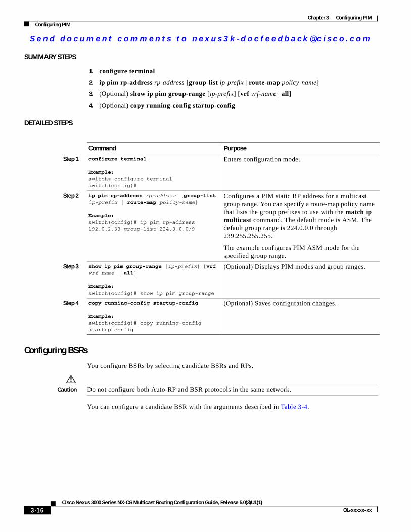
Se nd do cume nt c ommen ts t o nex us3k -d oc fee dba ck@c i sc o . co m
Chapter 3 Configuring PIMConfiguring PIM
SUMMARY STEPS
1. configure terminal
2. ip pim rp-address rp-address [group-list ip-prefix | route-map policy-name]
3. (Optional) show ip pim group-range [ip-prefix] [vrf vrf-name | all]
4. (Optional) copy running-config startup-config
DETAILED STEPS
Configuring BSRs
You configure BSRs by selecting candidate BSRs and RPs.
Caution Do not configure both Auto-RP and BSR protocols in the same network.
You can configure a candidate BSR with the arguments described in Table 3-4.
Command Purpose
Step 1 configure terminal
Example:switch# configure terminalswitch(config)#
Enters configuration mode.
Step 2 ip pim rp-address rp-address [group-list ip-prefix | route-map policy-name]
Example:switch(config)# ip pim rp-address 192.0.2.33 group-list 224.0.0.0/9
Configures a PIM static RP address for a multicast group range. You can specify a route-map policy name that lists the group prefixes to use with the match ip multicast command. The default mode is ASM. The default group range is 224.0.0.0 through 239.255.255.255.
The example configures PIM ASM mode for the specified group range.
Step 3 show ip pim group-range [ip-prefix] [vrf vrf-name | all]
Example:switch(config)# show ip pim group-range
(Optional) Displays PIM modes and group ranges.
Step 4 copy running-config startup-config
Example:switch(config)# copy running-config startup-config
(Optional) Saves configuration changes.
3-16Cisco Nexus 3000 Series NX-OS Multicast Routing Configuration Guide, Release 5.0(3)U1(1)
OL-xxxxx-xx
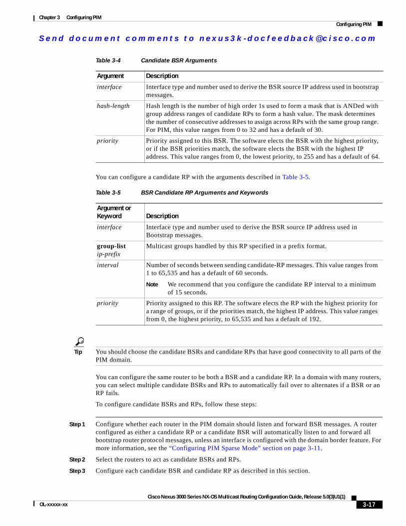
Se nd do cume nt c ommen ts t o nex us3k -d oc fee dba ck@c i sc o . co m
Chapter 3 Configuring PIMConfiguring PIM
You can configure a candidate RP with the arguments described in Table 3-5.
Tip You should choose the candidate BSRs and candidate RPs that have good connectivity to all parts of the PIM domain.
You can configure the same router to be both a BSR and a candidate RP. In a domain with many routers, you can select multiple candidate BSRs and RPs to automatically fail over to alternates if a BSR or an RP fails.
To configure candidate BSRs and RPs, follow these steps:
Step 1 Configure whether each router in the PIM domain should listen and forward BSR messages. A router configured as either a candidate RP or a candidate BSR will automatically listen to and forward all bootstrap router protocol messages, unless an interface is configured with the domain border feature. For more information, see the “Configuring PIM Sparse Mode” section on page 3-11.
Step 2 Select the routers to act as candidate BSRs and RPs.
Step 3 Configure each candidate BSR and candidate RP as described in this section.
Table 3-4 Candidate BSR Arguments
Argument Description
interface Interface type and number used to derive the BSR source IP address used in bootstrap messages.
hash-length Hash length is the number of high order 1s used to form a mask that is ANDed with group address ranges of candidate RPs to form a hash value. The mask determines the number of consecutive addresses to assign across RPs with the same group range. For PIM, this value ranges from 0 to 32 and has a default of 30.
priority Priority assigned to this BSR. The software elects the BSR with the highest priority, or if the BSR priorities match, the software elects the BSR with the highest IP address. This value ranges from 0, the lowest priority, to 255 and has a default of 64.
Table 3-5 BSR Candidate RP Arguments and Keywords
Argument or Keyword Description
interface Interface type and number used to derive the BSR source IP address used in Bootstrap messages.
group-list ip-prefix
Multicast groups handled by this RP specified in a prefix format.
interval Number of seconds between sending candidate-RP messages. This value ranges from 1 to 65,535 and has a default of 60 seconds.
Note We recommend that you configure the candidate RP interval to a minimum of 15 seconds.
priority Priority assigned to this RP. The software elects the RP with the highest priority for a range of groups, or if the priorities match, the highest IP address. This value ranges from 0, the highest priority, to 65,535 and has a default of 192.
3-17Cisco Nexus 3000 Series NX-OS Multicast Routing Configuration Guide, Release 5.0(3)U1(1)
OL-xxxxx-xx
Se nd do cume nt c ommen ts t o nex us3k -d oc fee dba ck@c i sc o . co m
Chapter 3 Configuring PIMConfiguring PIM
Step 4 Configure BSR message filtering. See the “Configuring Message Filtering” section on page 3-28.
BEFORE YOU BEGIN
Ensure that you have installed the LAN Base Services license and enabled PIM.
SUMMARY STEPS
1. configure terminal
2. ip pim [bsr] bsr-candidate interface [hash-len hash-length] [priority priority]
3. ip pim [bsr] rp-candidate interface group-list ip-prefix [priority priority] [interval interval]
4. (Optional) show ip pim group-range [ip-prefix] [vrf vrf-name | all]
5. (Optional) copy running-config startup-config
DETAILED STEPS
Command Purpose
Step 1 configure terminal
Example:switch# configure terminalswitch(config)#
Enters configuration mode.
Step 2 ip pim [bsr] bsr-candidate interface [hash-len hash-length] [priority priority]
Example:switch(config)# ip pim bsr-candidate ethernet 2/1 hash-len 24
Configures a candidate bootstrap router (BSR). The source IP address used in a bootstrap message is the IP address of the interface. The hash length ranges from 0 to 32 and has a default of 30. The priority ranges from 0 to 255 and has a default of 64. For parameter details, see Table 3-4.
Step 3 ip pim [bsr] rp-candidate interface group-list ip-prefix [priority priority] [interval interval]
Example:switch(config)# ip pim rp-candidate ethernet 2/1 group-list 239.0.0.0/24
Configures a candidate RP for BSR. The priority ranges from 0, the highest priority, to 65,535 and has a default of 192. The interval ranges from 1 to 65,535 seconds and has a default of 60.
Note We recommend that you configure the candidate RP interval to a minimum of 15 seconds.
The example configures an ASM candidate RP.
Step 4 show ip pim group-range [ip-prefix] [vrf vrf-name | all]
Example:switch(config)# show ip pim group-range
(Optional) Displays PIM modes and group ranges.
Step 5 copy running-config startup-config
Example:switch(config)# copy running-config startup-config
(Optional) Saves configuration changes.
3-18Cisco Nexus 3000 Series NX-OS Multicast Routing Configuration Guide, Release 5.0(3)U1(1)
OL-xxxxx-xx
Se nd do cume nt c ommen ts t o nex us3k -d oc fee dba ck@c i sc o . co m
Chapter 3 Configuring PIMConfiguring PIM
Configuring Auto-RP
You can configure Auto-RP by selecting candidate mapping agents and RPs. You can configure the same router to be both a mapping agent and a candidate RP.
Caution Do not configure both Auto-RP and BSR protocols in the same network.
You can configure an Auto-RP mapping agent with the arguments described in Table 3-6.
If you configure multiple Auto-RP mapping agents, only one is elected as the mapping agent for the domain. The elected mapping agent ensures that all candidate RP messages are sent out. All mapping agents receive the candidate RP messages and advertise the same RP cache in their RP-discovery messages.
You can configure a candidate RP with the arguments described in Table 3-7.
Table 3-6 Auto-RP Mapping Agent Arguments
Argument Description
interface Interface type and number used to derive the IP address of the Auto-RP mapping agent used in bootstrap messages.
scope ttl Time-To-Live (TTL) value that represents the maximum number of hops that RP-Discovery messages are forwarded. This value can range from 1 to 255 and has a default of 32.
Note See the border domain feature in the “Configuring PIM Sparse Mode” section on page 3-11.
Table 3-7 Auto-RP Candidate RP Arguments and Keywords
Argument or Keyword Description
interface Interface type and number used to derive the IP address of the candidate RP used in Bootstrap messages.
group-list ip-prefix
Multicast groups handled by this RP. Specified in a prefix format.
scope ttl Time-To-Live (TTL) value that represents the maximum number of hops that RP-Discovery messages are forwarded. This value can range from 1 to 255 and has a default of 32.
Note See the border domain feature in the “Configuring PIM Sparse Mode” section on page 3-11.
interval Number of seconds between sending RP-Announce messages. This value can range from 1 to 65,535 and has a default of 60.
Note We recommend that you configure the candidate RP interval to a minimum of 15 seconds.
3-19Cisco Nexus 3000 Series NX-OS Multicast Routing Configuration Guide, Release 5.0(3)U1(1)
OL-xxxxx-xx
Se nd do cume nt c ommen ts t o nex us3k -d oc fee dba ck@c i sc o . co m
Chapter 3 Configuring PIMConfiguring PIM
Tip You should choose mapping agents and candidate RPs that have good connectivity to all parts of the PIM domain.
To configure Auto-RP mapping agents and candidate RPs, follow these steps:
Step 1 For each router in the PIM domain, configure whether that router should listen and forward Auto-RP messages. A router configured as either a candidate RP or an Auto-RP mapping agent will automatically listen to and forward all Auto-RP protocol messages, unless an interface is configured with the domain border feature. For more information, see the “Configuring PIM Sparse Mode” section on page 3-11.
Step 2 Select the routers to act as mapping agents and candidate RPs.
Step 3 Configure each mapping agent and candidate RP as described in this section.
Step 4 Configure Auto-RP message filtering. See the “Configuring Message Filtering” section on page 3-28.
BEFORE YOU BEGIN
Ensure that you have installed the LAN Base Services license and enabled PIM.
SUMMARY STEPS
1. configure terminal
2. ip pim {send-rp-discovery | {auto-rp mapping-agent}} interface [scope ttl]
3. ip pim {send-rp-announce | {auto-rp rp-candidate}} interface group-list ip-prefix [scope ttl] [interval interval]
4. (Optional) show ip pim group-range [ip-prefix] [vrf vrf-name | all]
5. (Optional) copy running-config startup-config
DETAILED STEPS
Command Purpose
Step 1 configure terminal
Example:switch# configure terminalswitch(config)#
Enters configuration mode.
Step 2 ip pim {send-rp-discovery | {auto-rp mapping-agent}} interface [scope ttl]
Example:switch(config)# ip pim auto-rp mapping-agent ethernet 2/1
Configures an Auto-RP mapping agent. The source IP address used in Auto-RP Discovery messages is the IP address of the interface. The default scope is 32. For parameter details, see Table 3-6.
3-20Cisco Nexus 3000 Series NX-OS Multicast Routing Configuration Guide, Release 5.0(3)U1(1)
OL-xxxxx-xx
Se nd do cume nt c ommen ts t o nex us3k -d oc fee dba ck@c i sc o . co m
Chapter 3 Configuring PIMConfiguring PIM
Configuring a PIM Anycast-RP Set
To configure a PIM Anycast-RP set, follow these steps:
Step 1 Select the routers in the PIM Anycast-RP set.
Step 2 Select an IP address for the PIM Anycast-RP set.
Step 3 Configure each peer RP and local address in the PIM Anycast-RP set as described in this section.
BEFORE YOU BEGIN
Ensure that you have installed the LAN Base Services license and enabled PIM.
SUMMARY STEPS
1. configure terminal
2. interface loopback number
3. ip address ip-prefix
4. exit
5. ip pim anycast-rp anycast-rp-address anycast-rp-peer-address
6. Repeat Step 5 using the same anycast-rp for each peer RP in the RP set
7. (Optional) show ip pim group-range [ip-prefix] [vrf vrf-name | all]
8. (Optional) copy running-config startup-config
Step 3 ip pim {send-rp-announce | {auto-rp rp-candidate}} interface group-list ip-prefix [scope ttl] [interval interval]
Example:switch(config)# ip pim auto-rp rp-candidate ethernet 2/1 group-list 239.0.0.0/24
Configures an Auto-RP candidate RP. The default scope is 32. The default interval is 60 seconds. By default, the command creates an ASM candidate RP. For parameter details, see Table 3-7.
Note We recommend that you configure the candidate RP interval to a minimum of 15 seconds.
The example configures an ASM candidate RP.
Step 4 show ip pim group-range [ip-prefix] [vrf vrf-name | all]
Example:switch(config)# show ip pim group-range
(Optional) Displays PIM modes and group ranges.
Step 5 copy running-config startup-config
Example:switch(config)# copy running-config startup-config
(Optional) Saves configuration changes.
Command Purpose
3-21Cisco Nexus 3000 Series NX-OS Multicast Routing Configuration Guide, Release 5.0(3)U1(1)
OL-xxxxx-xx
Se nd do cume nt c ommen ts t o nex us3k -d oc fee dba ck@c i sc o . co m
Chapter 3 Configuring PIMConfiguring PIM
DETAILED STEPS
Command Purpose
Step 1 configure terminal
Example:switch# configure terminalswitch(config)#
Enters configuration mode.
Step 2 interface loopback number
Example:switch(config)# interface loopback 0
Configures an interface loopback.
This example configures interface loopback 0.
Step 3 ip address ip-prefix
Example:switch(config-if)# ip address 192.0.2.3/32
Configures an IP address for this interface.
This example configures an IP address for the Anycast-RP.
Step 4 exit
Example:switch(config)# exit
Returns to configuration mode.
Step 5 ip pim anycast-rp anycast-rp-address anycast-rp-peer-address
Example:switch(config)# ip pim anycast-rp 192.0.2.3 192.0.2.31
Configures a PIM Anycast-RP peer address for the specified Anycast-RP address. Each command with the same Anycast-RP address forms an Anycast-RP set. The IP addresses of RPs are used for communication with RPs in the set.
Step 6 Repeat Step 5 using the same Anycast-RP address for each peer RP in the Anycast-RP set.
—
Step 7 ip [autoconfig | ip-address [secondary]] (Optional) Generates a link-local address from the link-local prefix and a modified EUI-64 format Interface Identifier, where the EUI-64 Interface Identifier is created from the relevant HSRP virtual MAC address. the ip-address...
(Optional) Virtual IP address for the virtual router (HSRP group). The IP address must be in the same subnet as the interface IP address. You must configure the virtual IP address for at least one of the routers in the HSRP group. Other routers in the group will pick up this address. The IP address can be an IPv4 address.
Step 8 show ip pim group-range [ip-prefix] [vrf vrf-name | all]
Example:switch(config)# show ip pim group-range
(Optional) Displays PIM modes and group ranges.
Step 9 copy running-config startup-config
Example:switch(config)# copy running-config startup-config
(Optional) Saves configuration changes.
3-22Cisco Nexus 3000 Series NX-OS Multicast Routing Configuration Guide, Release 5.0(3)U1(1)
OL-xxxxx-xx
Se nd do cume nt c ommen ts t o nex us3k -d oc fee dba ck@c i sc o . co m
Chapter 3 Configuring PIMConfiguring PIM
Configuring Shared Trees Only for ASM
You can configure shared trees only on the last-hop router for Any Source Multicast (ASM) groups, which means that the router never switches over from the shared tree to the SPT when a receiver joins an active group. You can specify a group range where the use of shared trees is to be enforced with the match ip multicast command. This option does not affect the normal operation of the router when a source tree join-prune message is received.
The default is disabled, which means that the software can switch over to source trees.
Note In ASM mode, only the last-hop router switches from the shared tree to the SPT.
BEFORE YOU BEGIN
Ensure that you have installed the LAN Base Services license and enabled PIM.
SUMMARY STEPS
1. configure terminal
2. ip pim use-shared-tree-only group-list policy-name
3. (Optional) show ip pim group-range [ip-prefix] [vrf vrf-name | all]
4. (Optional) copy running-config startup-config
DETAILED STEPS
Command Purpose
Step 1 configure terminal
Example:switch# configure terminalswitch(config)#
Enters configuration mode.
Step 2 ip pim use-shared-tree-only group-list policy-name
Example:switch(config)# ip pim use-shared-tree-only group-list my_group_policy
Builds only shared trees, which means that the software never switches over from the shared tree to the SPT. You specify a route-map policy name that lists the groups to use with the match ip multicast command. By default, the software triggers a PIM (S, G) join toward the source when it receives multicast packets for a source for which it has the (*, G) state.
Step 3 show ip pim group-range [ip-prefix] [vrf vrf-name | all]
Example:switch(config)# show ip pim group-range
(Optional) Displays PIM modes and group ranges.
Step 4 copy running-config startup-config
Example:switch(config)# copy running-config startup-config
(Optional) Saves configuration changes.
3-23Cisco Nexus 3000 Series NX-OS Multicast Routing Configuration Guide, Release 5.0(3)U1(1)
OL-xxxxx-xx
Se nd do cume nt c ommen ts t o nex us3k -d oc fee dba ck@c i sc o . co m
Chapter 3 Configuring PIMConfiguring PIM
Configuring SSMSource-Specific Multicast (SSM) is a multicast distribution mode where the software on the DR connected to a receiver that is requesting data for a multicast source builds a shortest path tree (SPT) to that source.
On an IPv4 network, a host can request multicast data for a specific source only if it is running IGMPv3 and the DR for that host is running IGMPv3. You will usually enable IGMPv3 when you configure an interface for PIM in the SSM mode. For hosts running IGMPv1 or IGMPv2, you can configure group to source mapping using SSM translation. For more information, see Chapter 2, “Configuring IGMP.”
You can configure the group range that is used by SSM by specifying values on the command line. By default, the SSM group range for PIM is 232.0.0.0/8.
You can specify a route-map policy name that lists the group prefixes to use with the match ip multicast command.
Note If you want to use the default SSM group range, you do not need to configure the SSM group range.
BEFORE YOU BEGIN
Ensure that you have installed the LAN Base Services license and enabled PIM.
SUMMARY STEPS
1. configure terminal
2. ip pim ssm {range {ip-prefix | none} | route-map policy-name}no ip pim ssm {range {ip-prefix | none} | route-map policy-name}
3. (Optional) show ip pim group-range [ip-prefix] [vrf vrf-name | all]
4. (Optional) copy running-config startup-config
DETAILED STEPS
Command Purpose
Step 1 configure terminal
Example:switch# configure terminalswitch(config)#
Enters configuration mode.
Step 2 ip pim ssm range {ip-prefix | none} | route-map policy-name}
Example:switch(config)# ip pim ssm range 239.128.1.0/24
Configures up to four group ranges to be treated in SSM mode. You can specify a route-map policy name that lists the group prefixes to use with the match ip multicast command. The default range is 232.0.0.0/8. If the keyword none is specified, all group ranges are removed.
no ip pim ssm {range {ip-prefix | none} | route-map policy-name}
Example:switch(config)# no ip pim ssm range none
Removes the specified prefix from the SSM range, or removes the route-map policy. If the keyword none is specified, resets the SSM range to the default of 232.0.0.0/8.
3-24Cisco Nexus 3000 Series NX-OS Multicast Routing Configuration Guide, Release 5.0(3)U1(1)
OL-xxxxx-xx
Se nd do cume nt c ommen ts t o nex us3k -d oc fee dba ck@c i sc o . co m
Chapter 3 Configuring PIMConfiguring PIM
Setting the Maximum Number of Entries in the Multicast Routing TableYou can set the maximum number of entries in the multicast routing table.
BEFORE YOU BEGIN
Ensure that you have installed the LAN Base Services license and enabled PIM.
SUMMARY STEPS
1. configure terminal
1. hardware profile multicast max-limit max-entries
2. (Optional) show hardware profile status
3. (Optional) copy running-config startup-config
DETAILED STEPS
Step 3 show ip pim group-range [ip-prefix] [vrf vrf-name | all]
Example:switch(config)# show ip pim group-range
(Optional) Displays PIM modes and group ranges.
Step 4 copy running-config startup-config
Example:switch(config)# copy running-config startup-config
(Optional) Saves configuration changes.
Command Purpose
Command Purpose
Step 1 configure terminal
Example:switch# configure terminalswitch(config)#
Enters configuration mode.
Step 2 hardware profile multicast max-limit max-entriesExample:switch(config)# ip mroute 192.0.2.33/24 192.0.2.1
Sets the maximum number of entries in the multicast routing table. The range is from 0 to 4000.
The default is ____________
3-25Cisco Nexus 3000 Series NX-OS Multicast Routing Configuration Guide, Release 5.0(3)U1(1)
OL-xxxxx-xx
Se nd do cume nt c ommen ts t o nex us3k -d oc fee dba ck@c i sc o . co m
Chapter 3 Configuring PIMConfiguring PIM
Configuring RPF Routes for MulticastYou can define RPF routes for multicast when you want multicast data to diverge from the unicast traffic path. You can define RPF routes for multicast on border routers to enable reverse path forwarding (RPF) to an external network.
Multicast routes are used not to directly forward traffic but to make RPF checks. RPF routes for multicast cannot be redistributed. For more information about multicast forwarding, see the “Multicast Forwarding” section on page 1-4.
BEFORE YOU BEGIN
Ensure that you have installed the LAN Base Services license and enabled PIM.
SUMMARY STEPS
1. configure terminal
2. ip mroute {ip-addr mask | ip-prefix} {next-hop | nh-prefix | interface} [route-preference] [vrf vrf-name]
3. (Optional) show ip static-route [vrf vrf-name]
4. (Optional) copy running-config startup-config
DETAILED STEPS
Step 3 show hardware profile status
Example:switch(config)# show hardware profile status
(Optional) Displays the status of the entries in the multicast routing table.
Step 4 copy running-config startup-config
Example:switch(config)# copy running-config startup-config
(Optional) Saves configuration changes.
Command Purpose
Command Purpose
Step 1 configure terminal
Example:switch# configure terminalswitch(config)#
Enters configuration mode.
Step 2 ip mroute {ip-addr mask | ip-prefix} {next-hop | nh-prefix | interface} [route-preference] [vrf vrf-name]
Example:switch(config)# ip mroute 192.0.2.33/24 192.0.2.1
Configures an RPF route for multicast for use in RPF calculations. Route preference values range from 1 to 255. The default preference is 1.
3-26Cisco Nexus 3000 Series NX-OS Multicast Routing Configuration Guide, Release 5.0(3)U1(1)
OL-xxxxx-xx
Se nd do cume nt c ommen ts t o nex us3k -d oc fee dba ck@c i sc o . co m
Chapter 3 Configuring PIMConfiguring PIM
Configuring Route Maps to Control RP Information DistributionYou can configure route maps to help protect against some RP configuration errors and malicious attacks. You use route maps in commands that are described in the “Configuring Message Filtering” section on page 3-28.
By configuring route maps, you can control distribution of RP information that is distributed throughout the network. You specify the BSRs or mapping agents to be listened to on each client router and the list of candidate RPs to be advertised (listened to) on each BSR and mapping agent to ensure that what is advertised is what you expect.
Note Only the match ip multicast command has an effect in the route map.
BEFORE YOU BEGIN
Ensure that you have installed the LAN Base Services license and enabled PIM.
SUMMARY STEPS
1. configure terminal
2. route-map map-name [permit | deny] [sequence-number]
3. match ip multicast {{rp ip-address [rp-type rp-type] [group ip-prefix]} | {group ip-prefix [rp ip-address [rp-type rp-type]]}
4. (Optional) show route-map
5. (Optional) copy running-config startup-config
Step 3 show ip static-route [vrf vrf-name]
Example:switch(config)# show ip static-route
(Optional) Displays configured static routes.
Step 4 copy running-config startup-config
Example:switch(config)# copy running-config startup-config
(Optional) Saves configuration changes.
Command Purpose
3-27Cisco Nexus 3000 Series NX-OS Multicast Routing Configuration Guide, Release 5.0(3)U1(1)
OL-xxxxx-xx
Se nd do cume nt c ommen ts t o nex us3k -d oc fee dba ck@c i sc o . co m
Chapter 3 Configuring PIMConfiguring PIM
DETAILED STEPS
Configuring Message FilteringYou can configure filtering of the PIM messages described in Table 3-8.
Command Purpose
Step 1 configure terminal
Example:switch# configure terminalswitch(config)#
Enters configuration mode.
Step 2 route-map map-name [permit | deny] [sequence-number]
Example:switch(config)# route-map ASM_only permit 10switch(config-route-map)#
Enters route-map configuration mode. This configuration method uses the permit keyword.
Step 3 match ip multicast {{rp ip-address [rp-type rp-type] [group ip-prefix]} | {group ip-prefix [rp ip-address [rp-type rp-type]]}
Example:switch(config)# match ip multicast group 224.0.0.0/4 rp 0.0.0.0/0 rp-type ASM
Matches the group, RP, and RP type specified. You can specify the RP type (ASM). This configuration method requires the group and RP specified as shown in the examples.
Step 4 show route-map
Example:switch(config-route-map)# show route-map
(Optional) Displays configured route maps.
Step 5 copy running-config startup-config
Example:switch(config-route-map)# copy running-config startup-config
(Optional) Saves configuration changes.
Table 3-8 PIM Message Filtering
Message Type Description
Global to the switch
Log Neighbor changes Enables syslog messages that list the neighbor state changes to be generated. The default is disabled.
PIM register policy Enables PIM register messages to be filtered based on a route-map policy1 where you can specify group or group and source addresses with the match ip multicast command. This policy applies to routers that act as an RP. The default is disabled, which means that the software does not filter PIM register messages.
3-28Cisco Nexus 3000 Series NX-OS Multicast Routing Configuration Guide, Release 5.0(3)U1(1)
OL-xxxxx-xx
Se nd do cume nt c ommen ts t o nex us3k -d oc fee dba ck@c i sc o . co m
Chapter 3 Configuring PIMConfiguring PIM
For information about configuring multicast route maps, see the “Configuring Route Maps to Control RP Information Distribution” section on page 3-27.
BEFORE YOU BEGIN
Ensure that you have installed the LAN Base Services license and enabled PIM.
SUMMARY STEPS
1. configure terminal
2. (Optional) ip pim log-neighbor-changes
3. (Optional) ip pim register-policy policy-name
4. (Optional) ip pim bsr rp-candidate-policy policy-name
5. (Optional) ip pim bsr bsr-policy policy-name
6. (Optional) ip pim auto-rp rp-candidate-policy policy-name
7. (Optional) ip pim auto-rp mapping-agent-policy policy-name
BSR candidate RP policy
Enables BSR candidate RP messages to be filtered by the router based on a route-map policy1 where you can specify the RP and group addresses, and the type ASM with the match ip multicast command. This command can be used on routers that are eligible for BSR election. The default is no filtering of BSR messages.
BSR policy Enables BSR messages to be filtered by the BSR client routers based on a route-map policy1 where you can specify BSR source addresses with the match ip multicast command. This command can be used on client routers that listen to BSR messages. The default is no filtering of BSR messages.
Auto-RP candidate RP policy
Enables Auto-RP announce messages to be filtered by the Auto-RP mapping agents based on a route-map policy1 where you can specify the RP and group addresses, and the type ASM with the match ip multicast command. This command can be used on a mapping agent. The default is no filtering of Auto-RP messages.
Auto-RP mapping agent policy
Enables Auto-RP discover messages to be filtered by client routers based on a route-map policy1 where you can specify mapping agent source addresses with the match ip multicast command. This command can be used on client routers that listen to discover messages. The default is no filtering of Auto-RP messages.
Per switch interface
Join-prune policy Enables join-prune messages to be filtered based on a route-map policy1 where you can specify group, group and source, or group and RP addresses with the match ip multicast command. The default is no filtering of join-prune messages.
1. For information about configuring route-map policies, see the Cisco Nexus 3000 Series NX-OS Unicast Routing Configuration Guide.
Table 3-8 PIM Message Filtering (continued)
Message Type Description
3-29Cisco Nexus 3000 Series NX-OS Multicast Routing Configuration Guide, Release 5.0(3)U1(1)
OL-xxxxx-xx
Se nd do cume nt c ommen ts t o nex us3k -d oc fee dba ck@c i sc o . co m
Chapter 3 Configuring PIMConfiguring PIM
8. interface interface
9. no switchport
10. (Optional) ip pim jp-policy policy-name [in | out]
11. (Optional) show run pim
12. (Optional) copy running-config startup-config
DETAILED STEPS
Command Purpose
Step 1 configure terminal
Example:switch# configure terminalswitch(config)#
Enters configuration mode.
Step 2 ip pim log-neighbor-changes
Example:switch(config)# ip pim log-neighbor-changes
(Optional) Enables syslog messages that list the neighbor state changes to be generated. The default is disabled.
Step 3 ip pim register-policy policy-name
Example:switch(config)# ip pim register-policy my_register_policy
(Optional) Enables PIM register messages to be filtered based on a route-map policy. You can specify group or group and source addresses with the match ip multicast command.
Step 4 ip pim bsr rp-candidate-policy policy-name
Example:switch(config)# ip pim bsr rp-candidate-policy my_bsr_rp_candidate_policy
(Optional) Enables BSR candidate RP messages to be filtered by the router based on a route-map policy where you can specify the RP and group addresses, and the type ASM with the match ip multicast command. This command can be used on routers that are eligible for BSR election. The default is no filtering of BSR messages.
Step 5 ip pim bsr bsr-policy policy-name
Example:switch(config)# ip pim bsr bsr-policy my_bsr_policy
(Optional) Enables BSR messages to be filtered by the BSR client routers based on a route-map policy where you can specify BSR source addresses with the match ip multicast command. This command can be used on client routers that listen to BSR messages. The default is no filtering of BSR messages.
Step 6 ip pim auto-rp rp-candidate-policy policy-name
Example:switch(config)# ip pim auto-rp rp-candidate-policy my_auto_rp_candidate_policy
(Optional) Enables Auto-RP announce messages to be filtered by the Auto-RP mapping agents based on a route-map policy where you can specify the RP and group addresses, and the type ASM with the match ip multicast command. This command can be used on a mapping agent. The default is no filtering of Auto-RP messages.
3-30Cisco Nexus 3000 Series NX-OS Multicast Routing Configuration Guide, Release 5.0(3)U1(1)
OL-xxxxx-xx
Se nd do cume nt c ommen ts t o nex us3k -d oc fee dba ck@c i sc o . co m
Chapter 3 Configuring PIMConfiguring PIM
When routes are flushed, they are removed from the Multicast Routing Information Base (MRIB) and the Multicast Forwarding Information Base (MFIB).
When you restart PIM, the following tasks are performed:
• The PIM database is deleted.
• The MRIB and MFIB are unaffected and forwarding of traffic continues.
• The multicast route ownership is verified through the MRIB.
• Periodic PIM join and prune messages from neighbors are used to repopulate the database.
BEFORE YOU BEGIN
Ensure that you have installed the LAN Base Services license and enabled PIM.
SUMMARY STEPS
1. restart pim
2. configure terminal
Step 7 ip pim auto-rp mapping-agent-policy policy-name
Example:switch(config)# ip pim auto-rp mapping-agent-policy my_auto_rp_mapping_policy
(Optional) Enables Auto-RP discover messages to be filtered by client routers based on a route-map policy where you can specify mapping agent source addresses with the match ip multicast command. This command can be used on client routers that listen to discover messages. The default is no filtering of Auto-RP messages.
Step 8 interface interface
Example:switch(config)# interface ethernet 2/1switch(config-if)#
Enters interface mode on the specified interface.
Step 9 no switchport
Example:switch(config-if)# no switchport
Configures the interface as a Layer 3 routed interface.
Step 10 ip pim jp-policy policy-name [in | out]
Example:switch(config-if)# ip pim jp-policy my_jp_policy
(Optional) Enables join-prune messages to be filtered based on a route-map policy where you can specify group, group and source, or group and RP addresses with the match ip multicast command. The default is no filtering of join-prune messages.
This command filters messages in both incoming and outgoing directions.
Step 11 show run pim
Example:switch(config-if)# show run pim
(Optional) Displays PIM configuration commands.
Step 12 copy running-config startup-config
Example:switch(config-if)# copy running-config startup-config
(Optional) Saves configuration changes.
Command Purpose
3-31Cisco Nexus 3000 Series NX-OS Multicast Routing Configuration Guide, Release 5.0(3)U1(1)
OL-xxxxx-xx

Se nd do cume nt c ommen ts t o nex us3k -d oc fee dba ck@c i sc o . co m
Chapter 3 Configuring PIMVerifying the PIM Configuration
3. ip pim flush-routes
4. (Optional) show running-configuration pim
5. (Optional) copy running-config startup-config
DETAILED STEPS
Verifying the PIM ConfigurationTo display the PIM configuration information, perform one of the following tasks:
Command Purpose
Step 1 restart pim
Example:switch# restart pim
Restarts the PIM process.
Step 2 configure terminal
Example:switch# configure terminalswitch(config)#
Enters configuration mode.
Step 3 ip pim flush-routes
Example:switch(config)# ip pim flush-routes
Removes routes when the PIM process is restarted. By default, routes are not flushed.
Step 4 show running-configuration pim
Example:switch(config)# show running-configuration pim
(Optional) Shows the PIM running-configuration information, including the flush-routes command.
Step 5 copy running-config startup-config
Example:switch(config)# copy running-config startup-config
(Optional) Saves configuration changes.
Command Purpose
show ip mroute {source group | group [source]} [vrf vrf-name | all]
Displays the IP multicast routing table.
show ip pim group-range [vrf vrf-name | all] Displays the learned or configured group ranges and modes. For similar information, see also the show ip pim rp command.
show ip pim interface [interface | brief] [vrf vrf-name | all]
Displays information by the interface.
show ip pim neighbor [vrf vrf-name | all] Displays neighbors by the interface.
show ip pim oif-list group [source] [vrf vrf-name | all]
Displays all the interfaces in the OIF-list.
3-32Cisco Nexus 3000 Series NX-OS Multicast Routing Configuration Guide, Release 5.0(3)U1(1)
OL-xxxxx-xx
Se nd do cume nt c ommen ts t o nex us3k -d oc fee dba ck@c i sc o . co m
Chapter 3 Configuring PIMDisplaying Statistics
For detailed information about the fields in the output from these commands, see the Cisco Nexus 3000 Series Command Reference,.
Displaying StatisticsYou can display and clear PIM statistics by using the commands in this section.
This section has the following topics:
• Displaying PIM Statistics, page 3-33
• Clearing PIM Statistics, page 3-33
Displaying PIM StatisticsYou can display the PIM statistics and memory usage using the commands listed in Table 3-9. Use the show ip form of the command for PIM.
For detailed information about the fields in the output from these commands, see the Cisco Nexus 3000 Series Command Reference,.
Clearing PIM StatisticsYou can clear the PIM statistics using the commands listed in Table 3-10. Use the show ip form of the command for PIM.
show ip pim route {source group | group [source]} [vrf vrf-name | all]
Displays information for each multicast route, including interfaces on which a PIM join for that (S, G) has been received.
show ip pim rp [vrf vrf-name | all] Displays rendezvous points (RPs) known to the software, how they were learned, and their group ranges. For similar information, see also the show ip pim group-range command.
show ip pim rp-hash [vrf vrf-name | all] Displays the bootstrap router (BSR) RP hash information. For information about the RP hash, see RFC 5059.
show running-configuration pim Displays the running-configuration information.
show startup-configuration pim Displays the running-configuration information.
show ip pim vrf [vrf-name | all] [detail] Displays per-VRF information.
Command Purpose
Table 3-9 PIM Statistics Commands
Command Description
show ip pim policy statistics Displays policy statistics for Register, RP, and join-prune message policies.
3-33Cisco Nexus 3000 Series NX-OS Multicast Routing Configuration Guide, Release 5.0(3)U1(1)
OL-xxxxx-xx
Se nd do cume nt c ommen ts t o nex us3k -d oc fee dba ck@c i sc o . co m
Chapter 3 Configuring PIMConfiguration Examples for PIM
Configuration Examples for PIMThis section describes how to configure PIM using different data distribution modes and RP selection methods.
This section includes the following topics:
• Configuration Example for SSM, page 3-34
• Configuration Example for BSR, page 3-35
• Configuration Example for PIM Anycast-RP, page 3-36
Configuration Example for SSMTo configure PIM in SSM mode, follow these steps for each router in the PIM domain:
Step 1 Configure PIM sparse mode parameters on the interfaces that you want to participate in the domain. We recommend that you enable PIM on all interfaces.
switch# configure terminalswitch(config)# interface ethernet 2/1switch(config-if)# no switchportswitch(config-if)# ip pim sparse-mode
Step 2 Configure the parameters for IGMP that support SSM. See Chapter 2, “Configuring IGMP” Usually, you configure IGMPv3 on PIM interfaces to support SSM.
switch# configure terminalswitch(config)# interface ethernet 2/1switch(config-if)# no switchportswitch(config-if)# ip igmp version 3
Step 3 Configure the SSM range if you do not want to use the default range.
switch# configure terminalswitch(config)# ip pim ssm range 239.128.1.0/24
Step 4 Configure message filtering.
switch# configure terminalswitch(config)# ip pim log-neighbor-changes
This example shows how to configure PIM SSM mode:
Table 3-10 PIM Commands to Clear Statistics
Command Description
clear ip pim interface statistics interface Clears counters for the specified interface.
clear ip pim policy statistics Clears policy counters for Register, RP, and join-prune message policies.
clear ip pim statistics [vrf vrf-name | all] Clears global counters handled by the PIM process.
3-34Cisco Nexus 3000 Series NX-OS Multicast Routing Configuration Guide, Release 5.0(3)U1(1)
OL-xxxxx-xx
Se nd do cume nt c ommen ts t o nex us3k -d oc fee dba ck@c i sc o . co m
Chapter 3 Configuring PIMConfiguration Examples for PIM
configure terminal interface ethernet 2/1 no switchport ip pim sparse-mode ip igmp version 3 exit ip pim ssm range 239.128.1.0/24 ip pim log-neighbor-changes
Configuration Example for BSRTo configure PIM in ASM mode using the BSR mechanism, follow these steps for each router in the PIM domain:
Step 1 Configure PIM sparse mode parameters on the interfaces that you want to participate in the domain. We recommend that you enable PIM on all interfaces.
switch# configure terminalswitch(config)# interface ethernet 2/1switch(config-if)# no switchportswitch(config-if)# ip pim sparse-mode
Step 2 Configure whether that router should listen and forward BSR messages.
switch# configure terminalswitch(config)# ip pim bsr forward listen
Step 3 Configure the BSR parameters for each router that you want to act as a BSR.
switch# configure terminalswitch(config)# ip pim bsr-candidate ethernet 2/1 hash-len 30
Step 4 Configure the RP parameters for each router that you want to act as a candidate RP.
switch# configure terminalswitch(config)# ip pim rp-candidate ethernet 2/1 group-list 239.0.0.0/24
Step 5 Configure message filtering.
switch# configure terminalswitch(config)# ip pim log-neighbor-changes
This example shows how to configure PIM ASM mode using the BSR mechanism and how to configure the BSR and RP on the same router:
configure terminal interface ethernet 2/1 no switchport ip pim sparse-mode exit ip pim bsr forward listenip pim bsr-candidate ethernet 2/1 hash-len 30 ip pim rp-candidate ethernet 2/1 group-list 239.0.0.0/24 ip pim log-neighbor-changes
3-35Cisco Nexus 3000 Series NX-OS Multicast Routing Configuration Guide, Release 5.0(3)U1(1)
OL-xxxxx-xx
Se nd do cume nt c ommen ts t o nex us3k -d oc fee dba ck@c i sc o . co m
Chapter 3 Configuring PIMConfiguration Examples for PIM
Configuration Example for PIM Anycast-RPTo configure ASM mode using the PIM Anycast-RP method, follow these steps for each router in the PIM domain:
Step 1 Configure PIM sparse mode parameters on the interfaces that you want to participate in the domain. We recommend that you enable PIM on all interfaces.
switch# configure terminalswitch(config)# interface ethernet 2/1switch(config-if)# no switchportswitch(config-if)# ip pim sparse-mode
Step 2 Configure the RP address that you configure on all routers in the Anycast-RP set.
switch# configure terminalswitch(config)# interface loopback 0switch(config-if)# ip address 192.0.2.3/32
Step 3 Configure a loopback with an address to use in communication between routers in the Anycast-RP set for each router that you want to be in the Anycast-RP set.
switch# configure terminalswitch(config)# interface loopback 1switch(config-if)# ip address 192.0.2.31/32
Step 4 Configure the RP-address which will be used as Anycast-RP on all routers.
switch# configure terminalswitch(config)# ip pim rp-address 192.0.2.3
Step 5 Configure the Anycast-RP parameters and repeat with the IP address of each Anycast-RP for each router that you want to be in the Anycast-RP set. This example shows two Anycast-RPs.
switch# configure terminalswitch(config)# ip pim anycast-rp 192.0.2.3 193.0.2.31switch(config)# ip pim anycast-rp 192.0.2.3 193.0.2.32
Step 6 Configure message filtering.
switch# configure terminalswitch(config)# ip pim log-neighbor-changes
This example shows how to configure PIM ASM mode using two Anycast-RPs:
configure terminal interface ethernet 2/1 no switchport ip pim sparse-mode exit interface loopback 0 ip address 192.0.2.3/32 exit ip pim anycast-rp 192.0.2.3 192.0.2.31 ip pim anycast-rp 192.0.2.3 192.0.2.32 ip pim log-neighbor-changes
3-36Cisco Nexus 3000 Series NX-OS Multicast Routing Configuration Guide, Release 5.0(3)U1(1)
OL-xxxxx-xx
Se nd do cume nt c ommen ts t o nex us3k -d oc fee dba ck@c i sc o . co m
Chapter 3 Configuring PIMWhere to Go Next
Where to Go NextYou can configure the following features that work with PIM:
• Chapter 2, “Configuring IGMP”
• Chapter 4, “Configuring IGMP Snooping”
• Chapter 5, “Configuring MSDP”
Additional ReferencesFor additional information related to implementing PIM, see the following sections:
• Related Documents, page 3-37
• Standards, page 3-37
• MIBs, page 3-37
• Appendix A, “IETF RFCs for IP Multicast”
• Feature History for PIM, page 3-38
Related Documents
Standards
MIBs
Related Topic Document Title
CLI commands Cisco Nexus 3000 Series Command Reference,
Configuring VRFs Cisco Nexus 3000 Series NX-OS Unicast Routing Configuration Guide
Standards Title
No new or modified standards are supported by this feature, and support for existing standards has not been modified by this feature.
—
MIBs MIBs Link
IPMCAST-MIB To locate and download MIBs, go to the following URL:
http://www.cisco.com/public/sw-center/netmgmt/cmtk/mibs.shtml
3-37Cisco Nexus 3000 Series NX-OS Multicast Routing Configuration Guide, Release 5.0(3)U1(1)
OL-xxxxx-xx

Se nd do cume nt c ommen ts t o nex us3k -d oc fee dba ck@c i sc o . co m
Chapter 3 Configuring PIMFeature History for PIM
Feature History for PIMTable 3-11 lists the release history for this feature.
Table 3-11 Feature History for PIM
Feature Name Releases Feature Information
PIM 5.0(3)U1(1) This feature was introduced.
3-38Cisco Nexus 3000 Series NX-OS Multicast Routing Configuration Guide, Release 5.0(3)U1(1)
OL-xxxxx-xx
Se nd do cume nt c ommen ts t o nex us3k -d oc fee dba ck@c i sc o . co m
Cisco Nexus 3000 Series NX-OS MulticaOL-xxxxx-xx
C H A P T E R 4
Configuring IGMP SnoopingThis chapter describes how to configure Internet Group Management Protocol (IGMP) snooping on a Cisco NX-OS switch.
This chapter includes the following sections:
• Information About IGMP Snooping, page 4-1
• Licensing Requirements for IGMP Snooping, page 4-4
• Prerequisites for IGMP Snooping, page 4-4
• Default Settings, page 4-4
• Configuring IGMP Snooping Parameters, page 4-5
• Verifying the IGMP Snooping Configuration, page 4-7
• Displaying IGMP Snooping Statistics, page 4-8
• Configuration Examples for IGMP Snooping, page 4-8
• Where to Go Next, page 4-8
• Additional References, page 4-8
• Feature History for IGMP Snooping, page 4-9
Information About IGMP Snooping
Note We recommend that you do not disable IGMP snooping on the switch. If you disable IGMP snooping, you may see reduced multicast performance because of excessive false flooding within the switch.
The Internet Group Management Protocol (IGMP) snooping software examines Layer 2 IP multicast traffic within a VLAN to discover the ports where interested receivers reside. Using the port information, IGMP snooping can reduce bandwidth consumption in a multi-access LAN environment to avoid flooding the entire VLAN. The IGMP snooping feature tracks which ports are attached to multicast-capable routers to help the routers forward IGMP membership reports. The IGMP snooping software responds to topology change notifications. By default, IGMP snooping is enabled on the switch.
Figure 4-1 shows an IGMP snooping switch that sits between the host and the IGMP router. The IGMP snooping switch snoops the IGMP membership reports and Leave messages and forwards them only when necessary to the connected IGMP routers.
4-1st Routing Configuration Guide, Release 5.0(3)U1(1)
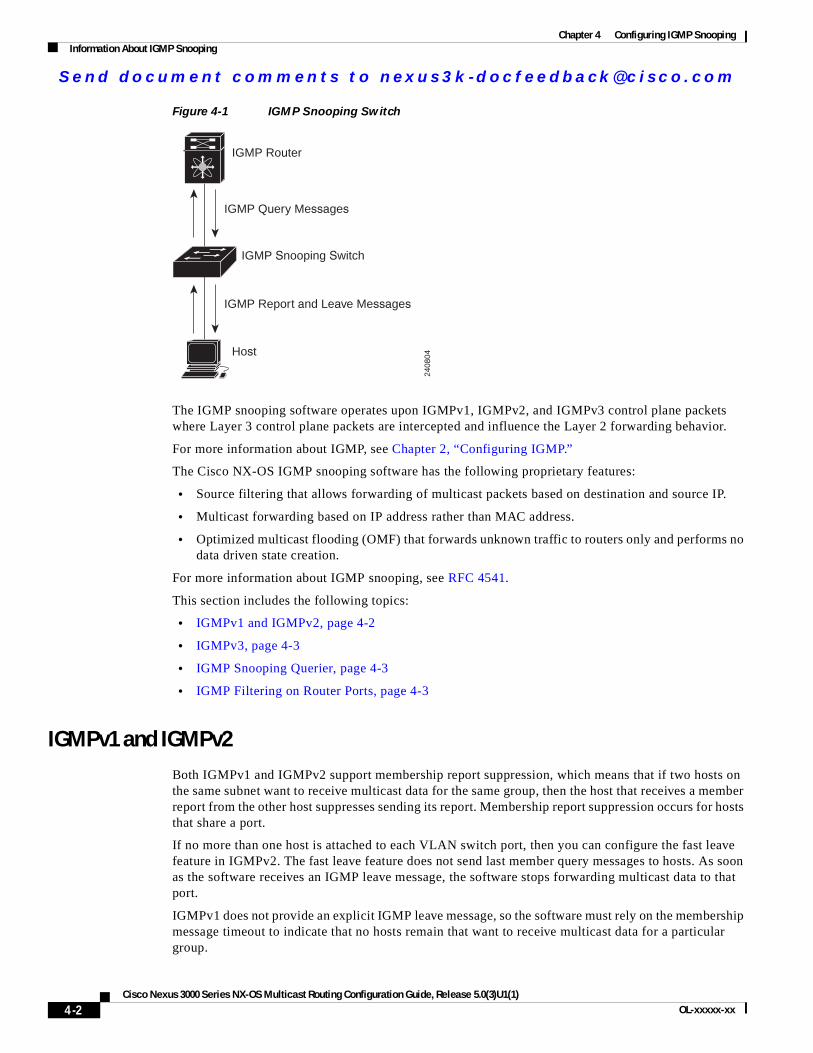
Se nd do cume nt c ommen ts t o nex us3k -d oc fee dba ck@c i sc o . co m
Chapter 4 Configuring IGMP SnoopingInformation About IGMP Snooping
Figure 4-1 IGMP Snooping Switch
The IGMP snooping software operates upon IGMPv1, IGMPv2, and IGMPv3 control plane packets where Layer 3 control plane packets are intercepted and influence the Layer 2 forwarding behavior.
For more information about IGMP, see Chapter 2, “Configuring IGMP.”
The Cisco NX-OS IGMP snooping software has the following proprietary features:
• Source filtering that allows forwarding of multicast packets based on destination and source IP.
• Multicast forwarding based on IP address rather than MAC address.
• Optimized multicast flooding (OMF) that forwards unknown traffic to routers only and performs no data driven state creation.
For more information about IGMP snooping, see RFC 4541.
This section includes the following topics:
• IGMPv1 and IGMPv2, page 4-2
• IGMPv3, page 4-3
• IGMP Snooping Querier, page 4-3
• IGMP Filtering on Router Ports, page 4-3
IGMPv1 and IGMPv2Both IGMPv1 and IGMPv2 support membership report suppression, which means that if two hosts on the same subnet want to receive multicast data for the same group, then the host that receives a member report from the other host suppresses sending its report. Membership report suppression occurs for hosts that share a port.
If no more than one host is attached to each VLAN switch port, then you can configure the fast leave feature in IGMPv2. The fast leave feature does not send last member query messages to hosts. As soon as the software receives an IGMP leave message, the software stops forwarding multicast data to that port.
IGMPv1 does not provide an explicit IGMP leave message, so the software must rely on the membership message timeout to indicate that no hosts remain that want to receive multicast data for a particular group.
2408
04
IGMP Router
IGMP Snooping Switch
Host
IGMP Query Messages
IGMP Report and Leave Messages
4-2Cisco Nexus 3000 Series NX-OS Multicast Routing Configuration Guide, Release 5.0(3)U1(1)
OL-xxxxx-xx
Se nd do cume nt c ommen ts t o nex us3k -d oc fee dba ck@c i sc o . co m
Chapter 4 Configuring IGMP SnoopingInformation About IGMP Snooping
Note The software ignores the configuration of the last member query interval when you enable the fast leave feature because it does not check for remaining hosts.
IGMPv3The IGMPv3 snooping implementation on Cisco NX-OS supports full IGMPv3 snooping, which provides constrained flooding based on the (S, G) information in the IGMPv3 reports. This source-based filtering enables the switch to constrain multicast traffic to a set of ports based on the source that sends traffic to the multicast group.
By default, the software tracks hosts on each VLAN port. The explicit tracking feature provides a fast leave mechanism. Because every IGMPv3 host sends membership reports, report suppression limits the amount of traffic that the switch sends to other multicast-capable routers. When report suppression is enabled, and no IGMPv1 or IGMPv2 hosts requested the same group, the software provides proxy reporting. The proxy feature builds the group state from membership reports from the downstream hosts and generates membership reports in response to queries from upstream queriers.
Even though the IGMPv3 membership reports provide a full accounting of group members on a LAN segment, when the last host leaves, the software sends a membership query. You can configure the parameter last member query interval. If no host responds before the timeout, the software removes the group state.
IGMP Snooping QuerierWhen PIM is not enabled on an interface because the multicast traffic does not need to be routed, you must configure an IGMP snooping querier to send membership queries. You define the querier in a VLAN that contains multicast sources and receivers but no other active querier.
When an IGMP snooping querier is enabled, it sends out periodic IGMP queries that trigger IGMP report messages from hosts that want to receive IP multicast traffic. IGMP snooping listens to these IGMP reports to establish appropriate forwarding.
IGMP Filtering on Router PortsIGMP filtering allows users to configure a router port on the switch that leads the switch to a Layer 3 multicast switch. The switch stores all manually configured static router ports in its router port list.
When an IGMP packet is received, the switch forwards the traffic through the router port in the VLAN. The switch recognizes a port as a router port through the PIM hello message or the IGMP query received by the switch.
IGMP Snooping with VRFsYou can define multiple virtual routing and forwarding (VRF) instances. An IGMP process supports all VRFs.
You can use the show commands with a VRF argument to provide a context for the information displayed. The default VRF is used if no VRF argument is supplied.
4-3Cisco Nexus 3000 Series NX-OS Multicast Routing Configuration Guide, Release 5.0(3)U1(1)
OL-xxxxx-xx
Se nd do cume nt c ommen ts t o nex us3k -d oc fee dba ck@c i sc o . co m
Chapter 4 Configuring IGMP SnoopingLicensing Requirements for IGMP Snooping
For information about configuring VRFs, see the Cisco Nexus 3000 Series NX-OS Unicast Routing Configuration Guide.
Licensing Requirements for IGMP SnoopingThe following table shows the licensing requirements for this feature:
Prerequisites for IGMP SnoopingIGMP snooping has the following prerequisites:
• You are logged onto the switch.
• For global commands, you are in the correct virtual routing and forwarding (VRF) mode. The default configuration mode shown in the examples in this chapter applies to the default VRF.
Default SettingsTable 4-1 lists the default settings for IGMP snooping parameters.
Product License Requirement
Cisco NX-OS IGMP snooping requires no license. Any feature not included in a license package is bundled with the Cisco NX-OS system images and is provided at no extra charge to you. For a complete explanation of the Cisco NX-OS licensing scheme, see the Cisco NX-OS Licensing Guide.
Note Make sure the LAN Base Services license is installed on the switch to enable the Layer 3 interfaces.
Table 4-1 Default IGMP Snooping Parameters
Parameters Default
IGMP snooping Enabled
Explicit tracking Enabled
Fast leave Disabled
Last member query interval 1 second
Snooping querier Disabled
Report suppression Enabled
Link-local groups suppression Enabled
IGMPv3 report suppression for the entire switch
Disabled
IGMPv3 report suppression per VLAN
Enabled
4-4Cisco Nexus 3000 Series NX-OS Multicast Routing Configuration Guide, Release 5.0(3)U1(1)
OL-xxxxx-xx
Se nd do cume nt c ommen ts t o nex us3k -d oc fee dba ck@c i sc o . co m
Chapter 4 Configuring IGMP SnoopingConfiguring IGMP Snooping Parameters
Configuring IGMP Snooping ParametersTo affect the operation of the IGMP snooping process, you can configure the optional IGMP snooping parameters described in Table 4-2.
SUMMARY STEPS
1. configure terminal
2. ip igmp snooping
3. vlan vlan-id
Table 4-2 IGMP Snooping Parameters
Parameter Description
IGMP snooping Enables IGMP snooping on the switch or on a per-VLAN basis. The default is enabled.
Note If the global setting is disabled, then all VLANs are treated as disabled, whether they are enabled or not.
Explicit tracking Tracks IGMPv3 membership reports from individual hosts for each port on a per-VLAN basis. The default is enabled.
Fast leave Enables the software to remove the group state when it receives an IGMP Leave report without sending an IGMP query message. This parameter is used for IGMPv2 hosts when no more than one host is present on each VLAN port. The default is disabled.
Last member query interval Sets the interval that the software waits after sending an IGMP query to verify that no hosts that want to receive a particular multicast group remain on a network segment. If no hosts respond before the last member query interval expires, the software removes the group from the associated VLAN port. Values range from 1 to 25 seconds. The default is 1 second.
Snooping querier Configures a snooping querier on an interface when you do not enable PIM because multicast traffic does not need to be routed.
Report suppression Limits the membership report traffic sent to multicast-capable routers on the switch or on a per-VLAN basis. When you disable report suppression, all IGMP reports are sent as is to multicast-capable routers. The default is enabled.
Multicast router Configures a static connection to a multicast router. The interface to the router must be in the selected VLAN.
Static group Configures a Layer 2 port of a VLAN as a static member of a multicast group.
Link-local groups suppression Configures link-local groups suppression on the switch or on a per-VLAN basis. The default is enabled.
IGMPv3 report suppression Configures IGMPv3 report suppression and proxy reporting on the switch or on a per-VLAN basis. The default is disabled for the entire switch and enabled per VLAN.
4-5Cisco Nexus 3000 Series NX-OS Multicast Routing Configuration Guide, Release 5.0(3)U1(1)
OL-xxxxx-xx

Se nd do cume nt c ommen ts t o nex us3k -d oc fee dba ck@c i sc o . co m
Chapter 4 Configuring IGMP SnoopingConfiguring IGMP Snooping Parameters
4. ip igmp snoopingip igmp snooping explicit-trackingip igmp snooping fast-leaveip igmp snooping last-member-query-interval secondsip igmp snooping querier ip-addressip igmp snooping report-suppressionip igmp snooping mrouter interface interfaceip igmp snooping static-group group-ip-addr [source source-ip-addr] interface interfaceip igmp snooping link-local-groups-suppressionip igmp snooping v3-report-suppression(Optional) copy running-config startup-config
DETAILED STEPS
Command Purpose
Step 1 configure terminal
Example:switch# configure terminalswitch(config)#
Enters configuration mode.
Step 2 ip igmp snooping
Example:switch(config)# ip igmp snooping
Enables IGMP snooping. The default is enabled.
Note If the global setting is disabled with the no form of this command, then IGMP snooping on all VLANs is disabled, whether IGMP snooping is enabled on a VLAN or not. If you disable IGMP snooping, Layer 2 multicast frames flood to all modules.
Step 3 vlan vlan-id
Example:switch(config)# vlan 2switch(config-vlan)#
Enters VLAN configuration mode.
Step 4 ip igmp snooping
Example:switch(config-vlan)# ip igmp snooping
Enables IGMP snooping for the current VLAN. The default is enabled.
ip igmp snooping explicit-tracking
Example:switch(config-vlan)# ip igmp snooping explicit-tracking
Tracks IGMPv3 membership reports from individual hosts for each port on a per-VLAN basis. The default is enabled on all VLANs.
ip igmp snooping fast-leave
Example:switch(config-vlan)# ip igmp snooping fast-leave
Supports IGMPv2 hosts that cannot be explicitly tracked because of the host report suppression mechanism of the IGMPv2 protocol. When you enable fast leave, the IGMP software assumes that no more than one host is present on each VLAN port. The default is disabled for all VLANs.
ip igmp snooping last-member-query-interval seconds
Example:switch(config-vlan)# ip igmp snooping last-member-query-interval 3
Removes the group from the associated VLAN port if no hosts respond to an IGMP query message before the last member query interval expires. Values range from 1 to 25 seconds. The default is 1 second.
4-6Cisco Nexus 3000 Series NX-OS Multicast Routing Configuration Guide, Release 5.0(3)U1(1)
OL-xxxxx-xx
Se nd do cume nt c ommen ts t o nex us3k -d oc fee dba ck@c i sc o . co m
Chapter 4 Configuring IGMP SnoopingVerifying the IGMP Snooping Configuration
Verifying the IGMP Snooping ConfigurationTo display the IGMP snooping configuration information, perform one of the following tasks:
ip igmp snooping querier ip-address
Example:switch(config-vlan)# ip igmp snooping querier 172.20.52.106
Configures a snooping querier when you do not enable PIM because multicast traffic does not need to be routed. The IP address is used as the source in messages.
ip igmp snooping report-suppression
Example:switch(config-vlan)# ip igmp snooping report-suppression
Limits the membership report traffic sent to multicast-capable routers. When you disable report suppression, all IGMP reports are sent as is to multicast-capable routers. The default is enabled.
Note This command can also be entered in global configuration mode to affect all interfaces.
ip igmp snooping mrouter interface interface
Example:switch(config-vlan)# ip igmp snooping mrouter interface ethernet 2/1
Configures a static connection to a multicast router. The interface to the router must be in the selected VLAN. You can specify the interface by the type and the number, such as ethernet slot/port.
ip igmp snooping static-group group-ip-addr [source source-ip-addr] interface interface
Example:switch(config-vlan)# ip igmp snooping static-group 230.0.0.1 interface ethernet 2/1
Configures a Layer 2 port of a VLAN as a static member of a multicast group. You can specify the interface by the type and the number, such as ethernet slot/port.
ip igmp snooping link-local-groups-suppression
Example:switch(config-vlan)# ip igmp snooping link-local-groups-suppression
Configures link-local groups suppression. The default is enabled.
Note This command can also be entered in global configuration mode to affect all interfaces.
ip igmp snooping v3-report-suppression
Example:switch(config-vlan)# ip igmp snooping v3-report-suppression
Configures IGMPv3 report suppression and proxy reporting. The default is disabled for the global command for the entire switch and enabled per VLAN.
Note This command can also be entered in global configuration mode to affect all interfaces.
Step 5 copy running-config startup-config
Example:switch(config)# copy running-config startup-config
(Optional) Saves configuration changes.
Command Purpose
Command Purpose
show ip igmp snooping [vlan vlan-id] Displays IGMP snooping configuration by VLAN.
show ip igmp snooping groups [source [group] | group [source]] [vlan vlan-id] [detail]
Displays IGMP snooping information about groups by VLAN.
4-7Cisco Nexus 3000 Series NX-OS Multicast Routing Configuration Guide, Release 5.0(3)U1(1)
OL-xxxxx-xx
Se nd do cume nt c ommen ts t o nex us3k -d oc fee dba ck@c i sc o . co m
Chapter 4 Configuring IGMP SnoopingDisplaying IGMP Snooping Statistics
For detailed information about the fields in the output from these commands, see the Cisco Nexus 3000 Series Command Reference,.
Displaying IGMP Snooping StatisticsUse the show ip igmp snooping statistics vlan command to display IGMP snooping statistics.
Use the clear ip igmp snooping statistics vlan command to clear IGMP snooping statistics.
For detailed information about using these commands, see the Cisco Nexus 3000 Series Command Reference,.
Configuration Examples for IGMP SnoopingThis example shows how to configure the IGMP snooping parameters:
configure terminal ip igmp snooping vlan 2 ip igmp snooping ip igmp snooping explicit-tracking ip igmp snooping fast-leave ip igmp snooping last-member-query-interval 3 ip igmp snooping querier 172.20.52.106 ip igmp snooping report-suppression ip igmp snooping mrouter interface ethernet 2/1 ip igmp snooping static-group 230.0.0.1 interface ethernet 2/1 ip igmp snooping link-local-groups-suppression ip igmp snooping v3-report-suppression
Where to Go NextYou can enable the following features that work with PIM:
• Chapter 2, “Configuring IGMP”
• Chapter 5, “Configuring MSDP”
Additional ReferencesFor additional information related to implementing IGMP snooping, see the following sections:
• Related Documents, page 4-9
show ip igmp snooping querier [vlan vlan-id] Displays IGMP snooping queriers by VLAN.
show ip igmp snooping mroute [vlan vlan-id] Displays multicast router ports by VLAN.
show ip igmp snooping explicit-tracking [vlan vlan-id]
Displays IGMP snooping explicit tracking information by VLAN.
Command Purpose
4-8Cisco Nexus 3000 Series NX-OS Multicast Routing Configuration Guide, Release 5.0(3)U1(1)
OL-xxxxx-xx
Se nd do cume nt c ommen ts t o nex us3k -d oc fee dba ck@c i sc o . co m
Chapter 4 Configuring IGMP SnoopingFeature History for IGMP Snooping
• Standards, page 4-9
• Feature History for IGMP Snooping, page 4-9
Related Documents
Standards
Feature History for IGMP SnoopingTable 4-3 lists the release history for this feature.
Related Topic Document Title
CLI commands Cisco Nexus 3000 Series Command Reference,
Standards Title
No new or modified standards are supported by this feature, and support for existing standards has not been modified by this feature.
—
Table 4-3 Feature History for IGMP Snooping
Feature Name Releases Feature Information
IGMP Snooping 5.0(3)U1(1) This feature was introduced.
4-9Cisco Nexus 3000 Series NX-OS Multicast Routing Configuration Guide, Release 5.0(3)U1(1)
OL-xxxxx-xx

Se nd do cume nt c ommen ts t o nex us3k -d oc fee dba ck@c i sc o . co m
Chapter 4 Configuring IGMP SnoopingFeature History for IGMP Snooping
4-10Cisco Nexus 3000 Series NX-OS Multicast Routing Configuration Guide, Release 5.0(3)U1(1)
OL-xxxxx-xx
Se nd do cume nt c ommen ts t o nex us3k -d oc fee dba ck@c i sc o . co m
Cisco Nexus 3000 Series NX-OS MulticaOL-xxxxx-xx
C H A P T E R 5
Configuring MSDPThis chapter describes how to configure Multicast Source Discovery Protocol (MSDP) on a Cisco NX-OS switch.
This chapter includes the following sections:
• Information About MSDP, page 5-1
• Licensing Requirements for MSDP, page 5-3
• Prerequisites for MSDP, page 5-4
• Default Settings, page 5-4
• Configuring MSDP, page 5-4
• Verifying the MSDP Configuration, page 5-13
• Displaying Statistics, page 5-14
• Configuration Examples for MSDP, page 5-15
• Additional References, page 5-16
Information About MSDPYou can use MSDP to exchange multicast source information between multiple BGP-enabled Protocol Independent Multicast (PIM) sparse-mode domains. For information about PIM, see Chapter 3, “Configuring PIM.” For information about BGP, see the Cisco Nexus 3000 Series NX-OS Unicast Routing Configuration Guide.
When a receiver for a group matches the group transmitted by a source in another domain, the rendezvous point (RP) sends PIM join messages in the direction of the source to build a shortest path tree. The designated router (DR) sends packets on the source-tree within the source domain, which may travel through the RP in the source domain and along the branches of the source-tree to other domains. In domains where there are receivers, RPs in those domains can be on the source-tree. The peering relationship is conducted over a TCP connection.
Figure 5-1 shows four PIM domains. The connected RPs (routers) are called MSDP peers because each RP maintains its own set of multicast sources. Source host 1 sends the multicast data to group 224.1.1.1. On RP 6, the MSDP process learns about the source through PIM register messages and generates Source-Active (SA) messages to its MSDP peers that contain information about the sources in its domain. When RP 3 and RP 5 receive the SA messages, they forward them to their MSDP peers. When RP 5 receives the request from host 2 for the multicast data on group 224.1.1.1, it builds a shortest path tree to the source by sending a PIM join message in the direction of host 1 at 192.1.1.1.
5-1st Routing Configuration Guide, Release 5.0(3)U1(1)
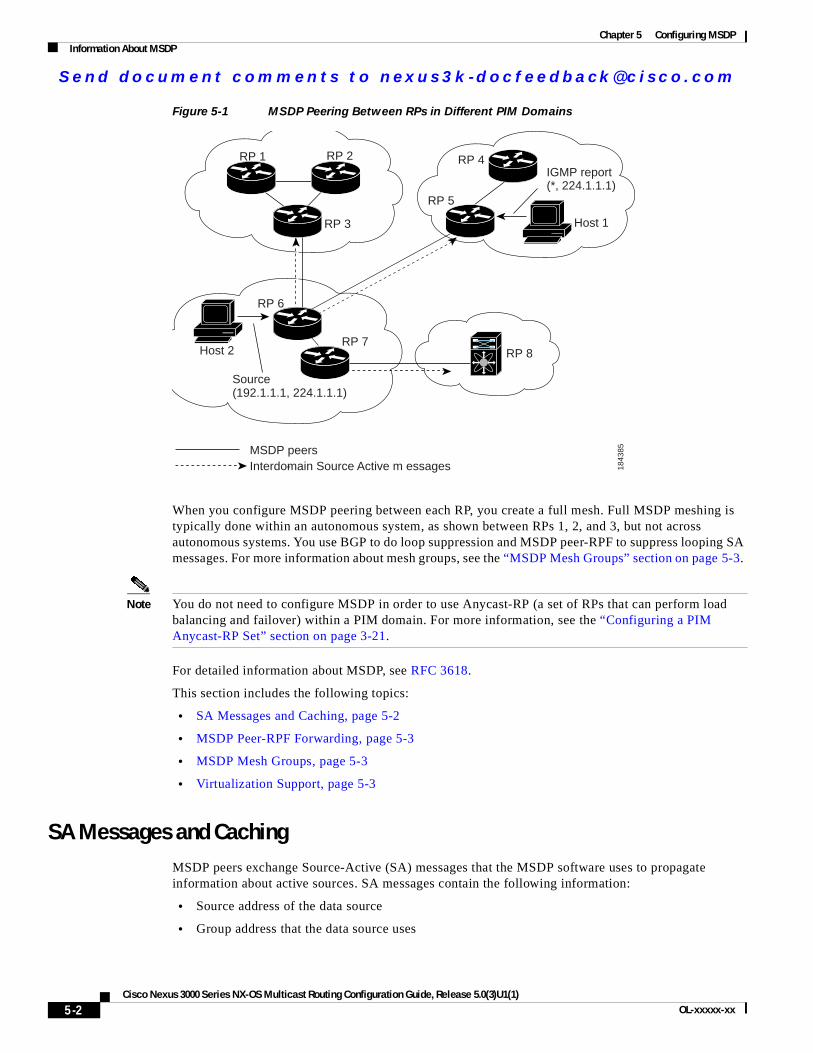
Se nd do cume nt c ommen ts t o nex us3k -d oc fee dba ck@c i sc o . co m
Chapter 5 Configuring MSDPInformation About MSDP
Figure 5-1 MSDP Peering Between RPs in Different PIM Domains
When you configure MSDP peering between each RP, you create a full mesh. Full MSDP meshing is typically done within an autonomous system, as shown between RPs 1, 2, and 3, but not across autonomous systems. You use BGP to do loop suppression and MSDP peer-RPF to suppress looping SA messages. For more information about mesh groups, see the “MSDP Mesh Groups” section on page 5-3.
Note You do not need to configure MSDP in order to use Anycast-RP (a set of RPs that can perform load balancing and failover) within a PIM domain. For more information, see the “Configuring a PIM Anycast-RP Set” section on page 3-21.
For detailed information about MSDP, see RFC 3618.
This section includes the following topics:
• SA Messages and Caching, page 5-2
• MSDP Peer-RPF Forwarding, page 5-3
• MSDP Mesh Groups, page 5-3
• Virtualization Support, page 5-3
SA Messages and CachingMSDP peers exchange Source-Active (SA) messages that the MSDP software uses to propagate information about active sources. SA messages contain the following information:
• Source address of the data source
• Group address that the data source uses
Source(192.1.1.1, 224.1.1.1)
IGMP report(*, 224.1.1.1)
MSDP peersInterdomain Source- Active m essages 18
4385
RP 5
RP 6
RP 7RP 8
RP 4RP 1 RP 2
RP 3
Host 2
Host 1
5-2Cisco Nexus 3000 Series NX-OS Multicast Routing Configuration Guide, Release 5.0(3)U1(1)
OL-xxxxx-xx
Se nd do cume nt c ommen ts t o nex us3k -d oc fee dba ck@c i sc o . co m
Chapter 5 Configuring MSDPLicensing Requirements for MSDP
• IP address of the RP or the configured originator ID
When a PIM register message advertises a new source, the MSDP process reencapsulates the message in an SA message that is immediately forwarded to all MSDP peers.
The SA cache holds the information for all sources learned through SA messages. Caching reduces the join latency for new receivers of a group because the information for all known groups can be found in the cache. You can limit the number of cached source entries by configuring the SA limit peer parameter. You can limit the number of cached source entries for a specific group prefix by configuring the group limit global parameter.
The MSDP software sends SA messages for each group in the SA cache every 60 seconds or at the configured SA interval global parameter. An entry in the SA cache is removed if an SA message for that source and group is not received within SA interval plus 3 seconds.
MSDP Peer-RPF ForwardingMSDP peers forward the SA messages that they receive away from the originating RP. This action is called peer-RPF flooding. The router examines the BGP routing table to determine which peer is the next hop in the direction of the originating RP of the SA message. This peer is called a reverse path forwarding (RPF) peer.
If the MSDP peer receives the same SA message from a non-RPF peer in the direction of the originating RP, it drops the message. Otherwise, it forwards the message to all its MSDP peers.
MSDP Mesh GroupsYou can use MSDP mesh groups to reduce the number of SA messages that are generated by peer-RPF flooding. In Figure 5-1, RPs 1, 2, and 3 receive SA messages from RP 6. By configuring a peering relationship between all the routers in a mesh and then configuring a mesh group of these routers, the SA messages that originate at a peer are sent by that peer to all other peers. SA messages received by peers in the mesh are not forwarded. An SA message that originates at RP 3 is forwarded to RP 1 and RP 2, but these RPs do not forward those messages to other RPs in the mesh.
A router can participate in multiple mesh groups. By default, no mesh groups are configured.
Virtualization SupportYou can define multiple virtual routing and forwarding (VRF) instances. The MSDP configuration applies to the selected VRF.
You can use the show commands with a VRF argument to provide a context for the information displayed. The default VRF is used if no VRF argument is supplied.
For information about configuring VRFs, see the Cisco Nexus 3000 Series NX-OS Unicast Routing Configuration Guide.
Licensing Requirements for MSDPThe following table shows the licensing requirements for this feature:
5-3Cisco Nexus 3000 Series NX-OS Multicast Routing Configuration Guide, Release 5.0(3)U1(1)
OL-xxxxx-xx
Se nd do cume nt c ommen ts t o nex us3k -d oc fee dba ck@c i sc o . co m
Chapter 5 Configuring MSDPPrerequisites for MSDP
Prerequisites for MSDPMSDP has the following prerequisites:
• You are logged onto the switch.
• For global commands, you are in the correct virtual routing and forwarding (VRF) mode. The default configuration mode shown in the examples in this chapter applies to the default VRF.
• You configured PIM for the networks where you want to configure MSDP.
• You configured BGP for the PIM domains where you want to configure MSDP.
Default SettingsTable 5-1 lists the default settings for MSDP parameters.
Configuring MSDPYou can establish MSDP peering by configuring the MSDP peers within each PIM domain.
To configure MSDP peering, follow these steps:
Step 1 Select the routers to act as MSDP peers.
Step 2 Enable the MSDP feature. See the “Enabling the MSDP Feature” section on page 5-5.
Step 3 Configure the MSDP peers for each router identified in Step 1. See the “Configuring MSDP Peers” section on page 5-6.
Product License Requirement
Cisco NX-OS MSDP requires a LAN Base Services license. For a complete explanation of the Cisco NX-OS licensing scheme and how to obtain and apply licenses, see the Cisco NX-OS Licensing Guide.
Table 5-1 Default MSDP Parameters
Parameters Default
Description Peer has no description
Administrative shutdown Peer is enabled when it is defined
MD5 password No MD5 password is enabled
SA policy IN All SA messages are received
SA policy OUT All registered sources are sent in SA messages
SA limit No limit is defined
Originator interface name RP address of the local system
Group limit No group limit is defined
SA interval 60 seconds
5-4Cisco Nexus 3000 Series NX-OS Multicast Routing Configuration Guide, Release 5.0(3)U1(1)
OL-xxxxx-xx
Se nd do cume nt c ommen ts t o nex us3k -d oc fee dba ck@c i sc o . co m
Chapter 5 Configuring MSDPConfiguring MSDP
Step 4 Configure the optional MSDP peer parameters for each MSDP peer. See the “Configuring MSDP Peer Parameters” section on page 5-7.
Step 5 Configure the optional global parameters for each MSDP peer. See the “Configuring MSDP Global Parameters” section on page 5-10.
Step 6 Configure the optional mesh groups for each MSDP peer. See the “Configuring MSDP Mesh Groups” section on page 5-11.
Note The MSDP commands that you enter before you enable MSDP are cached and then run when MSDP is enabled. Use the ip msdp peer or ip msdp originator-id command to enable MSDP.
This section includes the following topics:
• Enabling the MSDP Feature, page 5-5
• Configuring MSDP Peers, page 5-6
• Configuring MSDP Peer Parameters, page 5-7
• Configuring MSDP Global Parameters, page 5-10
• Configuring MSDP Mesh Groups, page 5-11
• Restarting the MSDP Process, page 5-12
Note If you are familiar with the Cisco IOS CLI, be aware that the Cisco NX-OS commands for this feature might differ from the Cisco IOS commands that you would use.
Enabling the MSDP FeatureBefore you can access the MSDP commands, you must enable the MSDP feature.
SUMMARY STEPS
1. configure terminal
2. feature msdp
3. (Optional) show running-configuration | grep feature
4. (Optional) copy running-config startup-config
5-5Cisco Nexus 3000 Series NX-OS Multicast Routing Configuration Guide, Release 5.0(3)U1(1)
OL-xxxxx-xx
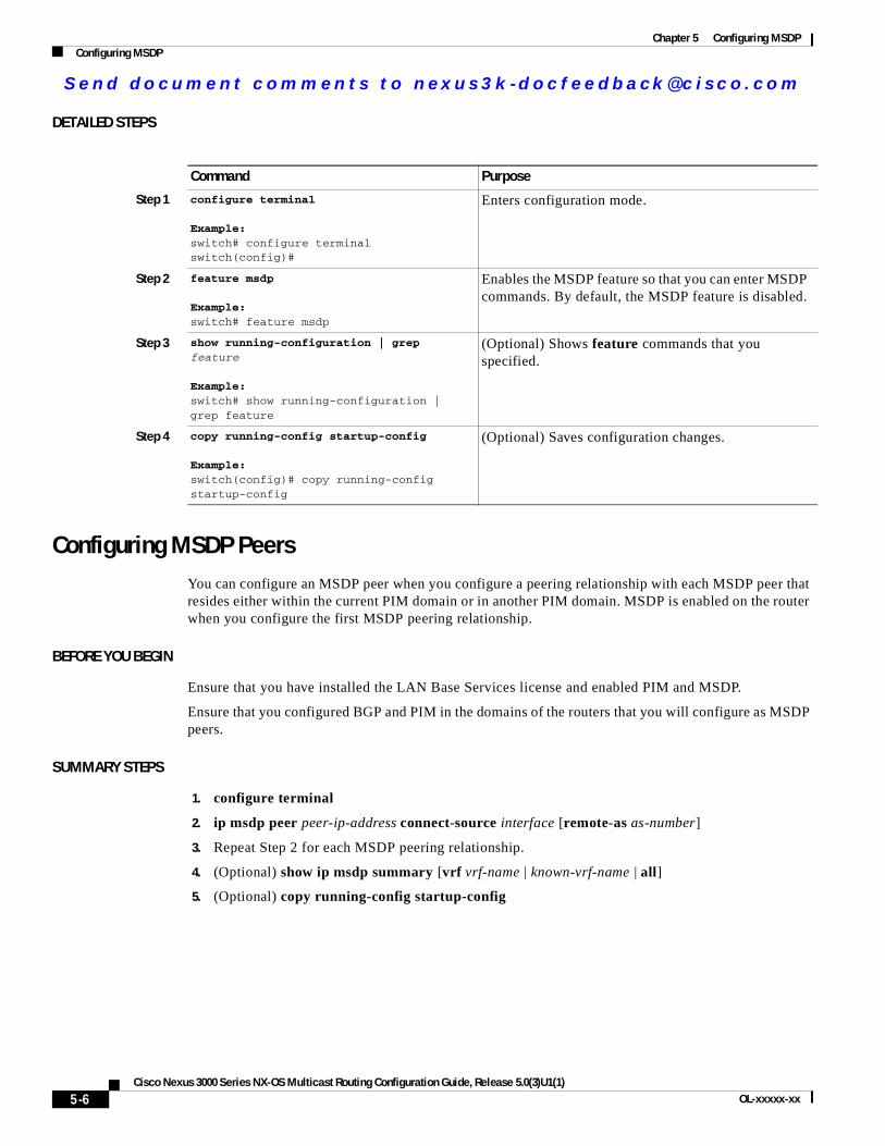
Se nd do cume nt c ommen ts t o nex us3k -d oc fee dba ck@c i sc o . co m
Chapter 5 Configuring MSDPConfiguring MSDP
DETAILED STEPS
Configuring MSDP PeersYou can configure an MSDP peer when you configure a peering relationship with each MSDP peer that resides either within the current PIM domain or in another PIM domain. MSDP is enabled on the router when you configure the first MSDP peering relationship.
BEFORE YOU BEGIN
Ensure that you have installed the LAN Base Services license and enabled PIM and MSDP.
Ensure that you configured BGP and PIM in the domains of the routers that you will configure as MSDP peers.
SUMMARY STEPS
1. configure terminal
2. ip msdp peer peer-ip-address connect-source interface [remote-as as-number]
3. Repeat Step 2 for each MSDP peering relationship.
4. (Optional) show ip msdp summary [vrf vrf-name | known-vrf-name | all]
5. (Optional) copy running-config startup-config
Command Purpose
Step 1 configure terminal
Example:switch# configure terminalswitch(config)#
Enters configuration mode.
Step 2 feature msdp
Example:switch# feature msdp
Enables the MSDP feature so that you can enter MSDP commands. By default, the MSDP feature is disabled.
Step 3 show running-configuration | grep feature
Example:switch# show running-configuration | grep feature
(Optional) Shows feature commands that you specified.
Step 4 copy running-config startup-config
Example:switch(config)# copy running-config startup-config
(Optional) Saves configuration changes.
5-6Cisco Nexus 3000 Series NX-OS Multicast Routing Configuration Guide, Release 5.0(3)U1(1)
OL-xxxxx-xx
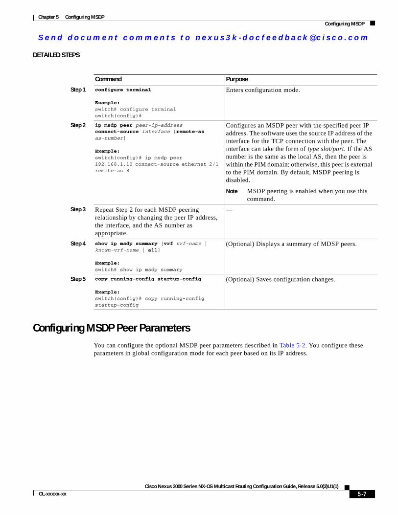
Se nd do cume nt c ommen ts t o nex us3k -d oc fee dba ck@c i sc o . co m
Chapter 5 Configuring MSDPConfiguring MSDP
DETAILED STEPS
Configuring MSDP Peer ParametersYou can configure the optional MSDP peer parameters described in Table 5-2. You configure these parameters in global configuration mode for each peer based on its IP address.
Command Purpose
Step 1 configure terminal
Example:switch# configure terminalswitch(config)#
Enters configuration mode.
Step 2 ip msdp peer peer-ip-address connect-source interface [remote-as as-number]
Example:switch(config)# ip msdp peer 192.168.1.10 connect-source ethernet 2/1 remote-as 8
Configures an MSDP peer with the specified peer IP address. The software uses the source IP address of the interface for the TCP connection with the peer. The interface can take the form of type slot/port. If the AS number is the same as the local AS, then the peer is within the PIM domain; otherwise, this peer is external to the PIM domain. By default, MSDP peering is disabled.
Note MSDP peering is enabled when you use this command.
Step 3 Repeat Step 2 for each MSDP peering relationship by changing the peer IP address, the interface, and the AS number as appropriate.
—
Step 4 show ip msdp summary [vrf vrf-name | known-vrf-name | all]
Example:switch# show ip msdp summary
(Optional) Displays a summary of MDSP peers.
Step 5 copy running-config startup-config
Example:switch(config)# copy running-config startup-config
(Optional) Saves configuration changes.
5-7Cisco Nexus 3000 Series NX-OS Multicast Routing Configuration Guide, Release 5.0(3)U1(1)
OL-xxxxx-xx
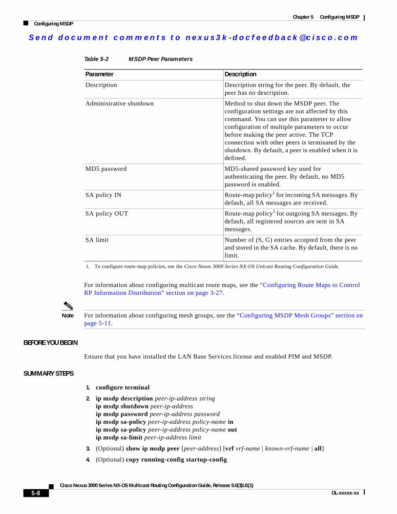
Se nd do cume nt c ommen ts t o nex us3k -d oc fee dba ck@c i sc o . co m
Chapter 5 Configuring MSDPConfiguring MSDP
For information about configuring multicast route maps, see the “Configuring Route Maps to Control RP Information Distribution” section on page 3-27.
Note For information about configuring mesh groups, see the “Configuring MSDP Mesh Groups” section on page 5-11.
BEFORE YOU BEGIN
Ensure that you have installed the LAN Base Services license and enabled PIM and MSDP.
SUMMARY STEPS
1. configure terminal
2. ip msdp description peer-ip-address stringip msdp shutdown peer-ip-addressip msdp password peer-ip-address passwordip msdp sa-policy peer-ip-address policy-name inip msdp sa-policy peer-ip-address policy-name outip msdp sa-limit peer-ip-address limit
3. (Optional) show ip msdp peer [peer-address] [vrf vrf-name | known-vrf-name | all]
4. (Optional) copy running-config startup-config
Table 5-2 MSDP Peer Parameters
Parameter Description
Description Description string for the peer. By default, the peer has no description.
Administrative shutdown Method to shut down the MSDP peer. The configuration settings are not affected by this command. You can use this parameter to allow configuration of multiple parameters to occur before making the peer active. The TCP connection with other peers is terminated by the shutdown. By default, a peer is enabled when it is defined.
MD5 password MD5-shared password key used for authenticating the peer. By default, no MD5 password is enabled.
SA policy IN Route-map policy1 for incoming SA messages. By default, all SA messages are received.
1. To configure route-map policies, see the Cisco Nexus 3000 Series NX-OS Unicast Routing Configuration Guide.
SA policy OUT Route-map policy1 for outgoing SA messages. By default, all registered sources are sent in SA messages.
SA limit Number of (S, G) entries accepted from the peer and stored in the SA cache. By default, there is no limit.
5-8Cisco Nexus 3000 Series NX-OS Multicast Routing Configuration Guide, Release 5.0(3)U1(1)
OL-xxxxx-xx
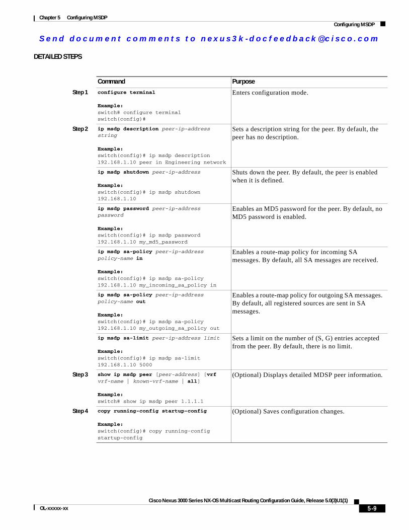
Se nd do cume nt c ommen ts t o nex us3k -d oc fee dba ck@c i sc o . co m
Chapter 5 Configuring MSDPConfiguring MSDP
DETAILED STEPS
Command Purpose
Step 1 configure terminal
Example:switch# configure terminalswitch(config)#
Enters configuration mode.
Step 2 ip msdp description peer-ip-address string
Example:switch(config)# ip msdp description 192.168.1.10 peer in Engineering network
Sets a description string for the peer. By default, the peer has no description.
ip msdp shutdown peer-ip-address
Example:switch(config)# ip msdp shutdown 192.168.1.10
Shuts down the peer. By default, the peer is enabled when it is defined.
ip msdp password peer-ip-address password
Example:switch(config)# ip msdp password 192.168.1.10 my_md5_password
Enables an MD5 password for the peer. By default, no MD5 password is enabled.
ip msdp sa-policy peer-ip-address policy-name in
Example:switch(config)# ip msdp sa-policy 192.168.1.10 my_incoming_sa_policy in
Enables a route-map policy for incoming SA messages. By default, all SA messages are received.
ip msdp sa-policy peer-ip-address policy-name out
Example:switch(config)# ip msdp sa-policy 192.168.1.10 my_outgoing_sa_policy out
Enables a route-map policy for outgoing SA messages. By default, all registered sources are sent in SA messages.
ip msdp sa-limit peer-ip-address limit
Example:switch(config)# ip msdp sa-limit 192.168.1.10 5000
Sets a limit on the number of (S, G) entries accepted from the peer. By default, there is no limit.
Step 3 show ip msdp peer [peer-address] [vrf vrf-name | known-vrf-name | all]
Example:switch# show ip msdp peer 1.1.1.1
(Optional) Displays detailed MDSP peer information.
Step 4 copy running-config startup-config
Example:switch(config)# copy running-config startup-config
(Optional) Saves configuration changes.
5-9Cisco Nexus 3000 Series NX-OS Multicast Routing Configuration Guide, Release 5.0(3)U1(1)
OL-xxxxx-xx
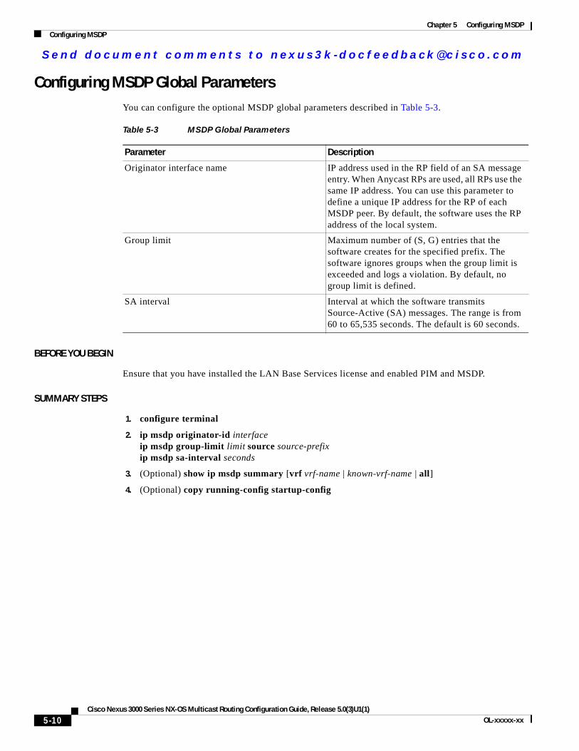
Se nd do cume nt c ommen ts t o nex us3k -d oc fee dba ck@c i sc o . co m
Chapter 5 Configuring MSDPConfiguring MSDP
Configuring MSDP Global ParametersYou can configure the optional MSDP global parameters described in Table 5-3.
BEFORE YOU BEGIN
Ensure that you have installed the LAN Base Services license and enabled PIM and MSDP.
SUMMARY STEPS
1. configure terminal
2. ip msdp originator-id interfaceip msdp group-limit limit source source-prefixip msdp sa-interval seconds
3. (Optional) show ip msdp summary [vrf vrf-name | known-vrf-name | all]
4. (Optional) copy running-config startup-config
Table 5-3 MSDP Global Parameters
Parameter Description
Originator interface name IP address used in the RP field of an SA message entry. When Anycast RPs are used, all RPs use the same IP address. You can use this parameter to define a unique IP address for the RP of each MSDP peer. By default, the software uses the RP address of the local system.
Group limit Maximum number of (S, G) entries that the software creates for the specified prefix. The software ignores groups when the group limit is exceeded and logs a violation. By default, no group limit is defined.
SA interval Interval at which the software transmits Source-Active (SA) messages. The range is from 60 to 65,535 seconds. The default is 60 seconds.
5-10Cisco Nexus 3000 Series NX-OS Multicast Routing Configuration Guide, Release 5.0(3)U1(1)
OL-xxxxx-xx
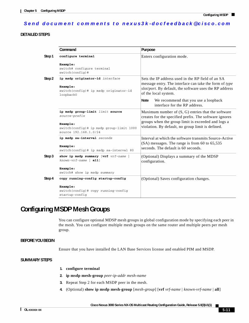
Se nd do cume nt c ommen ts t o nex us3k -d oc fee dba ck@c i sc o . co m
Chapter 5 Configuring MSDPConfiguring MSDP
DETAILED STEPS
Configuring MSDP Mesh GroupsYou can configure optional MDSP mesh groups in global configuration mode by specifying each peer in the mesh. You can configure multiple mesh groups on the same router and multiple peers per mesh group.
BEFORE YOU BEGIN
Ensure that you have installed the LAN Base Services license and enabled PIM and MSDP.
SUMMARY STEPS
1. configure terminal
2. ip msdp mesh-group peer-ip-addr mesh-name
3. Repeat Step 2 for each MSDP peer in the mesh.
4. (Optional) show ip msdp mesh-group [mesh-group] [vrf vrf-name | known-vrf-name | all]
Command Purpose
Step 1 configure terminal
Example:switch# configure terminalswitch(config)#
Enters configuration mode.
Step 2 ip msdp originator-id interface
Example:switch(config)# ip msdp originator-id loopback0
Sets the IP address used in the RP field of an SA message entry. The interface can take the form of type slot/port. By default, the software uses the RP address of the local system.
Note We recommend that you use a loopback interface for the RP address.
ip msdp group-limit limit source source-prefix
Example:switch(config)# ip msdp group-limit 1000 source 192.168.1.0/24
Maximum number of (S, G) entries that the software creates for the specified prefix. The software ignores groups when the group limit is exceeded and logs a violation. By default, no group limit is defined.
ip msdp sa-interval seconds
Example:switch(config)# ip msdp sa-interval 80
Interval at which the software transmits Source-Active (SA) messages. The range is from 60 to 65,535 seconds. The default is 60 seconds.
Step 3 show ip msdp summary [vrf vrf-name | known-vrf-name | all]
Example:switch# show ip msdp summary
(Optional) Displays a summary of the MDSP configuration.
Step 4 copy running-config startup-config
Example:switch(config)# copy running-config startup-config
(Optional) Saves configuration changes.
5-11Cisco Nexus 3000 Series NX-OS Multicast Routing Configuration Guide, Release 5.0(3)U1(1)
OL-xxxxx-xx
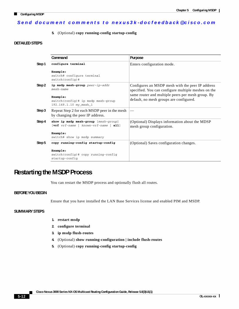
Se nd do cume nt c ommen ts t o nex us3k -d oc fee dba ck@c i sc o . co m
Chapter 5 Configuring MSDPConfiguring MSDP
5. (Optional) copy running-config startup-config
DETAILED STEPS
Restarting the MSDP ProcessYou can restart the MSDP process and optionally flush all routes.
BEFORE YOU BEGIN
Ensure that you have installed the LAN Base Services license and enabled PIM and MSDP.
SUMMARY STEPS
1. restart msdp
2. configure terminal
3. ip msdp flush-routes
4. (Optional) show running-configuration | include flush-routes
5. (Optional) copy running-config startup-config
Command Purpose
Step 1 configure terminal
Example:switch# configure terminalswitch(config)#
Enters configuration mode.
Step 2 ip msdp mesh-group peer-ip-addr mesh-name
Example:switch(config)# ip msdp mesh-group 192.168.1.10 my_mesh_1
Configures an MSDP mesh with the peer IP address specified. You can configure multiple meshes on the same router and multiple peers per mesh group. By default, no mesh groups are configured.
Step 3 Repeat Step 2 for each MSDP peer in the mesh by changing the peer IP address.
—
Step 4 show ip msdp mesh-group [mesh-group] [vrf vrf-name | known-vrf-name | all]
Example:switch# show ip msdp summary
(Optional) Displays information about the MDSP mesh group configuration.
Step 5 copy running-config startup-config
Example:switch(config)# copy running-config startup-config
(Optional) Saves configuration changes.
5-12Cisco Nexus 3000 Series NX-OS Multicast Routing Configuration Guide, Release 5.0(3)U1(1)
OL-xxxxx-xx
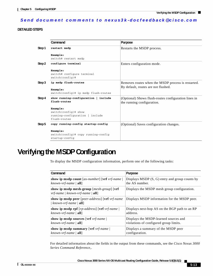
Se nd do cume nt c ommen ts t o nex us3k -d oc fee dba ck@c i sc o . co m
Chapter 5 Configuring MSDPVerifying the MSDP Configuration
DETAILED STEPS
Verifying the MSDP ConfigurationTo display the MSDP configuration information, perform one of the following tasks:
For detailed information about the fields in the output from these commands, see the Cisco Nexus 3000 Series Command Reference,.
Command Purpose
Step 1 restart msdp
Example:switch# restart msdp
Restarts the MSDP process.
Step 2 configure terminal
Example:switch# configure terminalswitch(config)#
Enters configuration mode.
Step 3 ip msdp flush-routes
Example:switch(config)# ip msdp flush-routes
Removes routes when the MSDP process is restarted. By default, routes are not flushed.
Step 4 show running-configuration | include flush-routes
Example:switch(config)# show running-configuration | include flush-routes
(Optional) Shows flush-routes configuration lines in the running configuration.
Step 5 copy running-config startup-config
Example:switch(config)# copy running-config startup-config
(Optional) Saves configuration changes.
Command Purpose
show ip msdp count [as-number] [vrf vrf-name | known-vrf-name | all]
Displays MSDP (S, G) entry and group counts by the AS number.
show ip msdp mesh-group [mesh-group] [vrf vrf-name | known-vrf-name | all]
Displays the MSDP mesh group configuration.
show ip msdp peer [peer-address] [vrf vrf-name | known-vrf-name | all]
Displays MSDP information for the MSDP peer.
show ip msdp rpf [rp-address] [vrf vrf-name | known-vrf-name | all]
Displays next-hop AS on the BGP path to an RP address.
show ip msdp sources [vrf vrf-name | known-vrf-name | all]
Displays the MSDP-learned sources and violations of configured group limits.
show ip msdp summary [vrf vrf-name | known-vrf-name | all]
Displays a summary of the MSDP peer configuration.
5-13Cisco Nexus 3000 Series NX-OS Multicast Routing Configuration Guide, Release 5.0(3)U1(1)
OL-xxxxx-xx
Se nd do cume nt c ommen ts t o nex us3k -d oc fee dba ck@c i sc o . co m
Chapter 5 Configuring MSDPDisplaying Statistics
Displaying StatisticsYou can display and clear MSDP statistics by using the features in this section.
This section has the following topics:
• Displaying Statistics, page 5-14
• Clearing Statistics, page 5-14
Displaying StatisticsYou can display MSDP statistics using the commands listed in Table 5-4.
Clearing StatisticsYou can clear the MSDP statistics using the commands listed in Table 5-5.
Table 5-4 MSDP Statistics Commands
Command Purpose
show ip msdp [as-number] internal event-history {errors | messages}
Displays memory allocation statistics.
show ip msdp policy statistics sa-policy peer-address {in | out} [vrf vrf-name | known-vrf-name | all]
Displays the MSDP policy statistics for the MSDP peer.
show ip msdp {sa-cache | route} [source-address] [group-address] [vrf vrf-name | known-vrf-name | all] [asn-number] [peer peer-address]
Displays the MSDP SA route cache. If you specify the source address, all groups for that source are displayed. If you specify a group address, all sources for that group are displayed.
Table 5-5 MSDP Clear Statistics Commands
Command Description
clear ip msdp peer [peer-address] [vrf vrf-name | known-vrf-name]
Clears the TCP connection to an MSDP peer.
clear ip msdp policy statistics sa-policy peer-address {in | out} [vrf vrf-name | known-vrf-name]
Clears statistics counters for MSDP peer SA policies.
clear ip msdp statistics [peer-address] [vrf vrf-name | known-vrf-name]
Clears statistics for MSDP peers.
clear ip msdp {sa-cache | route} [group-address] [vrf vrf-name | known-vrf-name | all]
Clears the group entries in the SA cache.
5-14Cisco Nexus 3000 Series NX-OS Multicast Routing Configuration Guide, Release 5.0(3)U1(1)
OL-xxxxx-xx
Se nd do cume nt c ommen ts t o nex us3k -d oc fee dba ck@c i sc o . co m
Chapter 5 Configuring MSDPConfiguration Examples for MSDP
Configuration Examples for MSDPTo configure MSDP peers, some of the optional parameters, and a mesh group, follow these steps for each MSDP peer:
Step 1 Configure the MSDP peering relationship with other routers.
switch# configure terminalswitch(config)# ip msdp peer 192.168.1.10 connect-source ethernet 1/0 remote-as 8
Step 2 Configure the optional peer parameters.
switch# configure terminalswitch(config)# ip msdp password 192.168.1.10 my_peer_password_AB
Step 3 Configure the optional global parameters.
switch# configure terminalswitch(config)# ip msdp sa-interval 80
Step 4 Configure the peers in each mesh group.
switch# configure terminalswitch(config)# ip msdp mesh-group 192.168.1.10 mesh_group_1
This example shows how to configure a subset of the MSDP peering that is shown in Figure 5-1.
• RP 3: 192.168.3.10 (AS 7)
configure terminal ip msdp peer 192.168.1.10 connect-source ethernet 1/1 ip msdp peer 192.168.2.10 connect-source ethernet 1/2 ip msdp peer 192.168.6.10 connect-source ethernet 1/3 remote-as 9 ip msdp password 192.168.6.10 my_peer_password_36 ip msdp sa-interval 80 ip msdp mesh-group 192.168.1.10 mesh_group_123 ip msdp mesh-group 192.168.2.10 mesh_group_123 ip msdp mesh-group 192.168.3.10 mesh_group_123
• RP 5: 192.168.5.10 (AS 8)
configure terminal ip msdp peer 192.168.4.10 connect-source ethernet 1/1 ip msdp peer 192.168.6.10 connect-source ethernet 1/2 remote-as 9 ip msdp password 192.168.6.10 my_peer_password_56 ip msdp sa-interval 80
• RP 6: 192.168.6.10 (AS 9)
configure terminal ip msdp peer 192.168.7.10 connect-source ethernet 1/1 ip msdp peer 192.168.3.10 connect-source ethernet 1/2 remote-as 7 ip msdp peer 192.168.5.10 connect-source ethernet 1/3 remote-as 8 ip msdp password 192.168.3.10 my_peer_password_36 ip msdp password 192.168.5.10 my_peer_password_56 ip msdp sa-interval 80
5-15Cisco Nexus 3000 Series NX-OS Multicast Routing Configuration Guide, Release 5.0(3)U1(1)
OL-xxxxx-xx
Se nd do cume nt c ommen ts t o nex us3k -d oc fee dba ck@c i sc o . co m
Chapter 5 Configuring MSDPAdditional References
Additional ReferencesFor additional information related to implementing MSDP, see the following sections:
• Related Documents, page 5-16
• Standards, page 5-16
• Appendix A, “IETF RFCs for IP Multicast”
Related Documents
Standards
Feature History for IGMPTable 5-6 lists the release history for this feature.
Related Topic Document Title
CLI commands Cisco Nexus 3000 Series Command Reference,
Standards Title
No new or modified standards are supported by this feature, and support for existing standards has not been modified by this feature.
—
Table 5-6 Feature History for MSDP
Feature Name Releases Feature Information
MSDP 5.0(3)U1(1) This feature was introduced.
5-16Cisco Nexus 3000 Series NX-OS Multicast Routing Configuration Guide, Release 5.0(3)U1(1)
OL-xxxxx-xx
Se nd do cume nt c ommen ts t o nex us3k -d oc fee dba ck@c i sc o . co m
Cisco Nexus 3000 Series NX-OS Multicast RouOL-xxxxx-xx
A
P P E N D I X A IETF RFCs for IP MulticastThis appendix contains Internet Engineering Task Force (IETF) RFCs related to IP multicast. For information about IETF RFCs, see http://www.ietf.org/rfc.html.
RFCs Title
RFC 2236 Internet Group Management Protocol, Version 2
RFC 2365 Administratively Scoped IP Multicast
RFC 2858 Multiprotocol Extensions for BGP-4
RFC 3376 Internet Group Management Protocol, Version 3
RFC 3446 Anycast Rendezvous Point (RP) mechanism using Protocol Independent Multicast (PIM) and Multicast Source Discovery Protocol (MSDP)
RFC 3569 An Overview of Source-Specific Multicast (SSM)
RFC 3618 Multicast Source Discovery Protocol (MSDP)
RFC 4541 Considerations for Internet Group Management Protocol (IGMP) Snooping Switches
RFC 4601 Protocol Independent Multicast - Sparse Mode (PIM-SM): Protocol Specification (Revised)
RFC 4610 Anycast-RP Using Protocol Independent Multicast (PIM)
RFC 5059 Bootstrap Router (BSR) Mechanism for Protocol Independent Multicast (PIM)
RFC 5132 IP Multicast MIB
A-1ting Configuration Guide, Release 5.0(3)U1(1)

Se nd do cume nt c ommen ts t o nex us3k -d oc fee dba ck@c i sc o . co m
Appendix A IETF RFCs for IP Multicast
A-2Cisco Nexus 3000 Series NX-OS Multicast Routing Configuration Guide, Release 5.0(3)U1(1)
OL-xxxxx-xx
Se nd do cume nt c ommen ts t o nex us3k -d oc fee dba ck@c i sc o . co m
Cisco Nexus 3000 Series NX-OS MulticaOL-xxxxx-xx
I N D E X
Symbols
(*, G)
description 1-4
state creation 3-3
static groups 2-6
static groups on the OIF 2-6
(S, G)
description 1-3
IGMPv3 snooping 4-3
state creation 3-3
static groups 2-6
static groups on the OIF 2-6
A
Anycast-RP
configuring an Anycast-RP set 3-21
description 3-6
MSDP (Note) 5-2
Any Source Multicast. See ASM mode
ASM mode
configuring 3-15
configuring shared trees only 3-23
description 3-2
join-prune messages 3-3
autonomous systems
MSDP 5-2
Auto-RP
candidate RP configuration steps 3-20
candidate RPs, configuring 3-19
configuring 3-19
description 3-5
mapping agent configuration steps 3-20
mapping agents
configuring 3-19
configuring route maps 3-27
RP-Announce messages 3-5
RP-Discovery messages 3-5
B
BGP
autonomous systems
MSDP 5-2
MSDP 5-2
bootstrap router. See BSRs
BSRs
candidate BSR configuration steps 3-17
candidate BSRs
configuring 3-16
description 3-4
candidate RP configuration steps 3-17
candidate-RP messages
description 3-4
candidate RPs, configuring 3-17
configuring 3-16
description 3-4
messages
description 3-4
enabling listen and forward 3-5
route maps, configuring 3-27
RP configuration steps 3-17
IN-1st Routing Configuration Guide, Release 5.0(3)U1(1)
Se nd do cume nt c ommen ts t o nex us3k -d oc fee dba ck@c i sc o . co m
Index
D
designated routers. See DRs
documentation
related documents i-xi
DRs
description 3-7
PIM domains 1-6
priority and PIM hello message 3-2
SSM mode 3-24
E
ECMP 3-2
equal-cost multipathing 3-2
I
IGMP
all-hosts multicast group 2-2
configuration, example 2-14
description 2-1
enabling 2-1
IGMPv3
changes from IGMPv2 2-2
description 2-3
SSM 2-3
licensing requirements 2-4
parameters
configuring 2-5
default settings 2-5
PIM domains 1-6
queriers
description 2-3
designated 2-2
TTL 2-3
version, default (IGMPv2) 2-2
versions, description 2-2
IGMP commands
IN-2Cisco Nexus 3000 Series NX-OS Multicast Routing Configuration G
iip igmp enforce-router-alert 2-13
ip igmp access-group 2-10
ip igmp flush-routes 2-13
ip igmp group-timeout 2-10
ip igmp immediate-leave 2-10
ip igmp join-group 2-9
ip igmp last-member-query-count 2-10
ip igmp last-member-query-response-time 2-10
ip igmp querier-timeout 2-9
ip igmp query-interval 2-10
ip igmp query-max-response-time 2-10
ip igmp query-timeout 2-9
ip igmp report-link-local-groups 2-10
ip igmp report-policy 2-10
ip igmp robustness-variable 2-9
ip igmp ssm-translate 2-12
ip igmp startup-query-count 2-9
ip igmp startup-query-interval 2-9
ip igmp static-oif 2-9
ip igmp version 2-8
IGMP configuration
access groups 2-7
example 2-14
group membership timeout 2-2, 2-7
immediate leave 2-7
last member query count 2-7
last member query response interval 2-7
member query response interval 2-4
number of query messages 2-3
parameters 2-5
parameters, default settings 2-5
querier timeout 2-6
query interval 2-7
query maximum response time 2-3
query max response time 2-6
report link local multicast groups 2-7
report policy 2-7
reports for link local addresses 2-4
robustness value 2-4, 2-6
uide, Release 5.0(3)U1(1)OL-xxxxx-xx
Se nd do cume nt c ommen ts t o nex us3k -d oc fee dba ck@c i sc o . co m
Index
startup query count 2-6
startup query interval 2-6
static multicast groups 2-6
Static multicast groups on OIF 2-6
version 2-6
IGMP membership reports
IGMPv3 suppression 2-3
initiating receipt of multicast data 2-2
SSM translation 2-11
suppressing 2-3
IGMP queriers
description 2-3
designated 2-2
TTL 2-3
IGMP show commands
show ip igmp groups 2-13
show ip igmp interface 2-13
show ip igmp local-groups 2-13
show ip igmp route 2-13
show running-configuration igmp 2-13
show startup-configuration igmp 2-13
IGMP snooping
configuration, example 4-8
description 4-1
licensing requirements 4-4
membership report suppression 4-2
parameters, configuring 4-5
parameters, default settings 4-4
prerequisites 4-4
proprietary features 4-2
querier, description 4-3
statistics 4-8
switch example 4-1
vPC statistics 4-8
IGMP snooping commands
ip igmp snooping 4-6
ip igmp snooping explicit-tracking 4-6
ip igmp snooping fast-leave 4-6
ip igmp snooping last-member-query-interval 4-6
Cisco Nexus 3000 Series NX-OOL-xxxxx-xx
ip igmp snooping link-local-groups-suppression 4-7
ip igmp snooping mrouter interface 4-7
ip igmp snooping querier 4-7
ip igmp snooping report-suppression 4-7
ip igmp snooping static-group 4-7
ip igmp snooping v3-report-suppression 4-7
IGMP snooping configuration
enabling 4-5
example 4-8
explicit tracking 4-5
fast leave 4-5
IGMPv3 report suppression 4-5
last member query interval 4-5
Link-local groups suppression 4-5
multicast routers 4-5
parameters
configuring 4-5
default settings 4-4
report suppression 4-5
snooping querier 4-5
static groups 4-5
IGMP snooping show commands
show ip igmp snooping 4-7
show ip igmp snooping explicit-tracking 4-8
show ip igmp snooping groups 4-7
show ip igmp snooping mroute 4-8
show ip igmp snooping querier 4-8
IGMPv3
changes from IGMPv2 2-2
description 2-3
SSM 2-3
interdomain multicast protocols
MSDP 1-8
SSM 1-8
Internet Group Management Protocol. See IGMP
L
licensing requirements, multicast 1-9
IN-3S Multicast Routing Configuration Guide, Release 5.0(3)U1(1)
Se nd do cume nt c ommen ts t o nex us3k -d oc fee dba ck@c i sc o . co m
Index
M
mapping agents. See Auto-RP
MFIB
description 1-9
flushing routes 3-31
MRIB and M6RIB
description 1-8
flushing routes 3-31
MSDP
Anycast-RP (Note) 5-2
configuration, example 5-15
description 5-1
full mesh, description 5-2
interdomain multicast protocol 1-8
licensing requirements 5-3
mesh groups, description 5-3
parameters, default settings 5-4
peering, steps to configure 5-4
peer-RPF flooding, description 5-3
peers, description 5-1
PIM domains 1-6, 5-1
prerequisites 5-4
SA cache, description 5-3
SA messages, and PIM register messages 5-3
SA messages, description 5-1, 5-2
statistics
clearing 5-14
displaying 5-14
MSDP commands
feature msdp 5-6
ip msdp description 5-9
ip msdp flush-routes 5-13
ip msdp group-limit 5-11
ip msdp mesh-group 5-12
ip msdp originator-id 5-11
ip msdp password 5-9
ip msdp peer 5-7
ip msdp sa-interval 5-11
IN-4Cisco Nexus 3000 Series NX-OS Multicast Routing Configuration G
ip msdp sa-limit 5-9
ip msdp sa-policy 5-9
ip msdp shutdown 5-9
MSDP configuration
administrative shutdown 5-8
commands, cached (Note) 5-5
description field 5-8
enabling 5-5
example 5-15
group limit 5-10
MD5 password 5-8
mesh groups 5-11
originator interface name 5-10
parameters, default settings
5-4
peering, steps to configure 5-4
peers and peering relationship 5-6
restarting the MSDP process 5-12
SA messages
interval 5-10
limit 5-8
policy IN 5-8
policy OUT 5-8
MSDP show commands
show ip msdp 5-14
show ip msdp count 5-13
show ip msdp mesh-group 5-13
show ip msdp peer 5-13
show ip msdp policy statistics sa-policy 5-14
show ip msdp route 5-14
show ip msdp rpf 5-13
show ip msdp sa-cache 5-14
show ip msdp sources 5-13
show ip msdp summary 5-13
MSDP statistics commands
clear ip msdp peer 5-14
clear ip msdp policy statistics sa-policy 5-14
clear ip msdp route 5-14
clear ip msdp sa-cache 5-14
uide, Release 5.0(3)U1(1)OL-xxxxx-xx
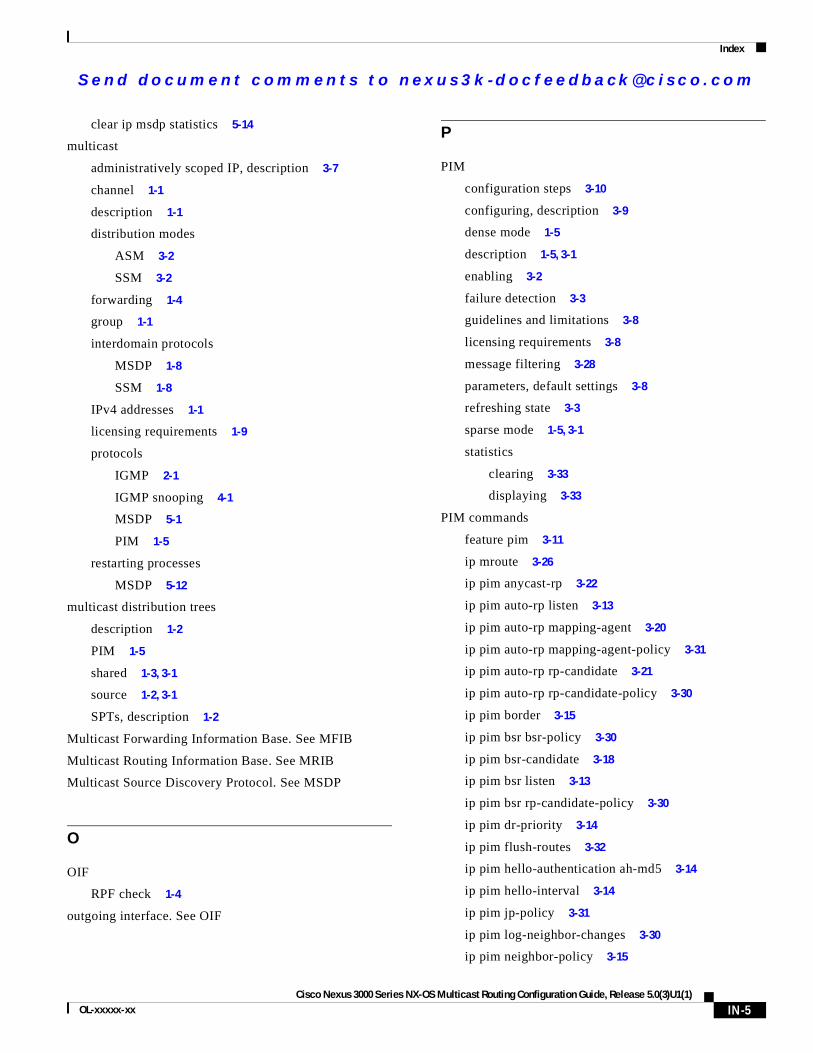
Se nd do cume nt c ommen ts t o nex us3k -d oc fee dba ck@c i sc o . co m
Index
clear ip msdp statistics 5-14
multicast
administratively scoped IP, description 3-7
channel 1-1
description 1-1
distribution modes
ASM 3-2
SSM 3-2
forwarding 1-4
group 1-1
interdomain protocols
MSDP 1-8
SSM 1-8
IPv4 addresses 1-1
licensing requirements 1-9
protocols
IGMP 2-1
IGMP snooping 4-1
MSDP 5-1
PIM 1-5
restarting processes
MSDP 5-12
multicast distribution trees
description 1-2
PIM 1-5
shared 1-3, 3-1
source 1-2, 3-1
SPTs, description 1-2
Multicast Forwarding Information Base. See MFIB
Multicast Routing Information Base. See MRIB
Multicast Source Discovery Protocol. See MSDP
O
OIF
RPF check 1-4
outgoing interface. See OIF
Cisco Nexus 3000 Series NX-OOL-xxxxx-xx
P
PIM
configuration steps 3-10
configuring, description 3-9
dense mode 1-5
description 1-5, 3-1
enabling 3-2
failure detection 3-3
guidelines and limitations 3-8
licensing requirements 3-8
message filtering 3-28
parameters, default settings 3-8
refreshing state 3-3
sparse mode 1-5, 3-1
statistics
clearing 3-33
displaying 3-33
PIM commands
feature pim 3-11
ip mroute 3-26
ip pim anycast-rp 3-22
ip pim auto-rp listen 3-13
ip pim auto-rp mapping-agent 3-20
ip pim auto-rp mapping-agent-policy 3-31
ip pim auto-rp rp-candidate 3-21
ip pim auto-rp rp-candidate-policy 3-30
ip pim border 3-15
ip pim bsr bsr-policy 3-30
ip pim bsr-candidate 3-18
ip pim bsr listen 3-13
ip pim bsr rp-candidate-policy 3-30
ip pim dr-priority 3-14
ip pim flush-routes 3-32
ip pim hello-authentication ah-md5 3-14
ip pim hello-interval 3-14
ip pim jp-policy 3-31
ip pim log-neighbor-changes 3-30
ip pim neighbor-policy 3-15
IN-5S Multicast Routing Configuration Guide, Release 5.0(3)U1(1)
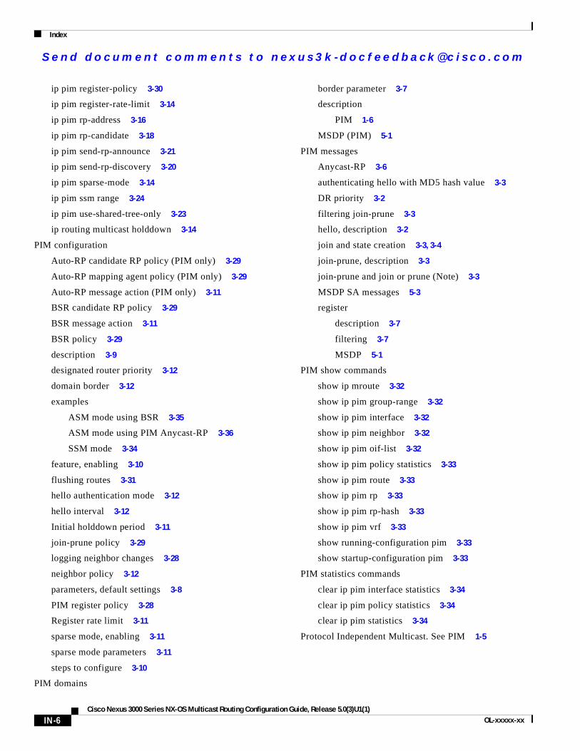
Se nd do cume nt c ommen ts t o nex us3k -d oc fee dba ck@c i sc o . co m
Index
ip pim register-policy 3-30
ip pim register-rate-limit 3-14
ip pim rp-address 3-16
ip pim rp-candidate 3-18
ip pim send-rp-announce 3-21
ip pim send-rp-discovery 3-20
ip pim sparse-mode 3-14
ip pim ssm range 3-24
ip pim use-shared-tree-only 3-23
ip routing multicast holddown 3-14
PIM configuration
Auto-RP candidate RP policy (PIM only) 3-29
Auto-RP mapping agent policy (PIM only) 3-29
Auto-RP message action (PIM only) 3-11
BSR candidate RP policy 3-29
BSR message action 3-11
BSR policy 3-29
description 3-9
designated router priority 3-12
domain border 3-12
examples
ASM mode using BSR 3-35
ASM mode using PIM Anycast-RP 3-36
SSM mode 3-34
feature, enabling 3-10
flushing routes 3-31
hello authentication mode 3-12
hello interval 3-12
Initial holddown period 3-11
join-prune policy 3-29
logging neighbor changes 3-28
neighbor policy 3-12
parameters, default settings 3-8
PIM register policy 3-28
Register rate limit 3-11
sparse mode, enabling 3-11
sparse mode parameters 3-11
steps to configure 3-10
PIM domains
IN-6Cisco Nexus 3000 Series NX-OS Multicast Routing Configuration G
border parameter 3-7
description
PIM 1-6
MSDP (PIM) 5-1
PIM messages
Anycast-RP 3-6
authenticating hello with MD5 hash value 3-3
DR priority 3-2
filtering join-prune 3-3
hello, description 3-2
join and state creation 3-3, 3-4
join-prune, description 3-3
join-prune and join or prune (Note) 3-3
MSDP SA messages 5-3
register
description 3-7
filtering 3-7
MSDP 5-1
PIM show commands
show ip mroute 3-32
show ip pim group-range 3-32
show ip pim interface 3-32
show ip pim neighbor 3-32
show ip pim oif-list 3-32
show ip pim policy statistics 3-33
show ip pim route 3-33
show ip pim rp 3-33
show ip pim rp-hash 3-33
show ip pim vrf 3-33
show running-configuration pim 3-33
show startup-configuration pim 3-33
PIM statistics commands
clear ip pim interface statistics 3-34
clear ip pim policy statistics 3-34
clear ip pim statistics 3-34
Protocol Independent Multicast. See PIM 1-5
uide, Release 5.0(3)U1(1)OL-xxxxx-xx
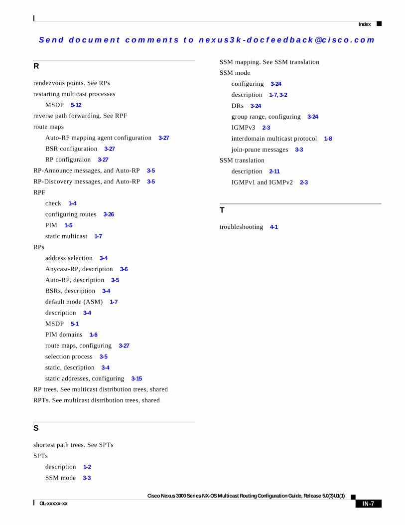
Se nd do cume nt c ommen ts t o nex us3k -d oc fee dba ck@c i sc o . co m
Index
R
rendezvous points. See RPs
restarting multicast processes
MSDP 5-12
reverse path forwarding. See RPF
route maps
Auto-RP mapping agent configuration 3-27
BSR configuration 3-27
RP configuraion 3-27
RP-Announce messages, and Auto-RP 3-5
RP-Discovery messages, and Auto-RP 3-5
RPF
check 1-4
configuring routes 3-26
PIM 1-5
static multicast 1-7
RPs
address selection 3-4
Anycast-RP, description 3-6
Auto-RP, description 3-5
BSRs, description 3-4
default mode (ASM) 1-7
description 3-4
MSDP 5-1
PIM domains 1-6
route maps, configuring 3-27
selection process 3-5
static, description 3-4
static addresses, configuring 3-15
RP trees. See multicast distribution trees, shared
RPTs. See multicast distribution trees, shared
S
shortest path trees. See SPTs
SPTs
description 1-2
SSM mode 3-3
Cisco Nexus 3000 Series NX-OOL-xxxxx-xx
SSM mapping. See SSM translation
SSM mode
configuring 3-24
description 1-7, 3-2
DRs 3-24
group range, configuring 3-24
IGMPv3 2-3
interdomain multicast protocol 1-8
join-prune messages 3-3
SSM translation
description 2-11
IGMPv1 and IGMPv2 2-3
T
troubleshooting 4-1
IN-7S Multicast Routing Configuration Guide, Release 5.0(3)U1(1)

Se nd do cume nt c ommen ts t o nex us3k -d oc fee dba ck@c i sc o . co m
Index
IN-8Cisco Nexus 3000 Series NX-OS Multicast Routing Configuration G
uide, Release 5.0(3)U1(1)OL-xxxxx-xx