pd series internal gear pumps - thybotech · connection type options bsp & npt threaded...
TRANSCRIPT
PD SERIES Internal Gear Pumps
2 3
APPLICATIONS & INDUSTRY
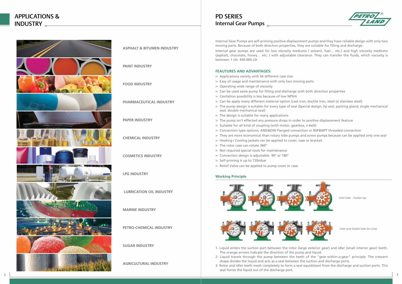
Internal Gear Pumps are self-priming positive displacement pumps and they have reliable design with only two moving parts. Because of both direction properties, they are suitable for filling and discharge.
Internal gear pumps are used for low viscosity mediums ( solvent, fuel… etc.) and high viscosity mediums (asphalt, chocolate, honey… etc. ) with adjustable clearance. They can transfer the fluids, which viscosity is between 1 cSt- 450.000 cSt
FEAUTURES AND ADVANTAGES: Applications variety with 56 different case size
Easy of usage and maintenance with only two moving parts
Operating wide range of viscosity
Can be used same pump for filling and discharge with both direction properties
Cavitation possibility is less because of low NPSHr
Can be apply many different material option (cast iron, ductile iron, steel or stainless steel)
The pump design is suitable for every type of seal (Special design, lip seal, packing gland, single mechanical seal, double mechanical seal)
The design is suitable for many applications
The pump isn’t effected any pressure drops in order to positive displacement feature
Suitable for all kind of coupling (with motor, gearbox, v-belt)
Connection type options, ANSI&DIN Flanged connection or BSP&NPT threaded connection
They are more economical than rotary lobe pumps and screw pumps because can be applied only one seal
Heating / Cooling jackets can be applied to cover, case or bracket
The rotor case can rotate 360°
Not required special tools for maintenance
Connection design is adjustable 90° or 180°
Self-priming is up to 720mbar
Relief Valve can be applied to pump cover or case
PD SERIESInternal Gear Pumps
1- Liquid enters the suction port between the rotor (large exterior gear) and idler (small interior gear) teeth. The orange arrows indicate the direction of the pump and liquid.
2- Liquid travels through the pump between the teeth of the "gear-within-a-gear" principle. The crescent shape divides the liquid and acts as a seal between the suction and discharge ports.
3- Rotor and idler teeth mesh completely to form a seal equidistant from the discharge and suction ports. This seal forces the liquid out of the discharge port.
Inlet Side – Outlet Up
Inlet and Outlet Side (In-Line)
ASPHALT & BITUMEN INDUSTRY
PAINT INDUSTRY
FOOD INDUSTRY
PHARMACEUTICAL INDUSTRY
PAPER INDUSTRY
CHEMICAL INDUSTRY
COSMETICS INDUSTRY
LPG INDUSTRY
LUBRICATION OIL INDUSTRY
MARINE INDUSTRY
PETRO-CHEMICAL INDUSTRY
SUGAR INDUSTRY
AGRICULTURAL INDUSTRY
Working Principle
4 5
FEATURES:
Applications variety with 8 different case size
Can be apply many different material option (cast iron, ductile iron, steel or stainless steel)
Operating low and medium viscosity
Self-priming is up to 720mbar
No need gearbox for low viscosity applications
The pump design is suitable for lip seal, packing gland and mechanical seal
It is economical solution with direct coupling
OPTIONS:
Heating / Cooling jacket can be applied to cover
Relief Valve can be applied to pump cover
Connection type options BSP & NPT threaded connection
Direct Coupling
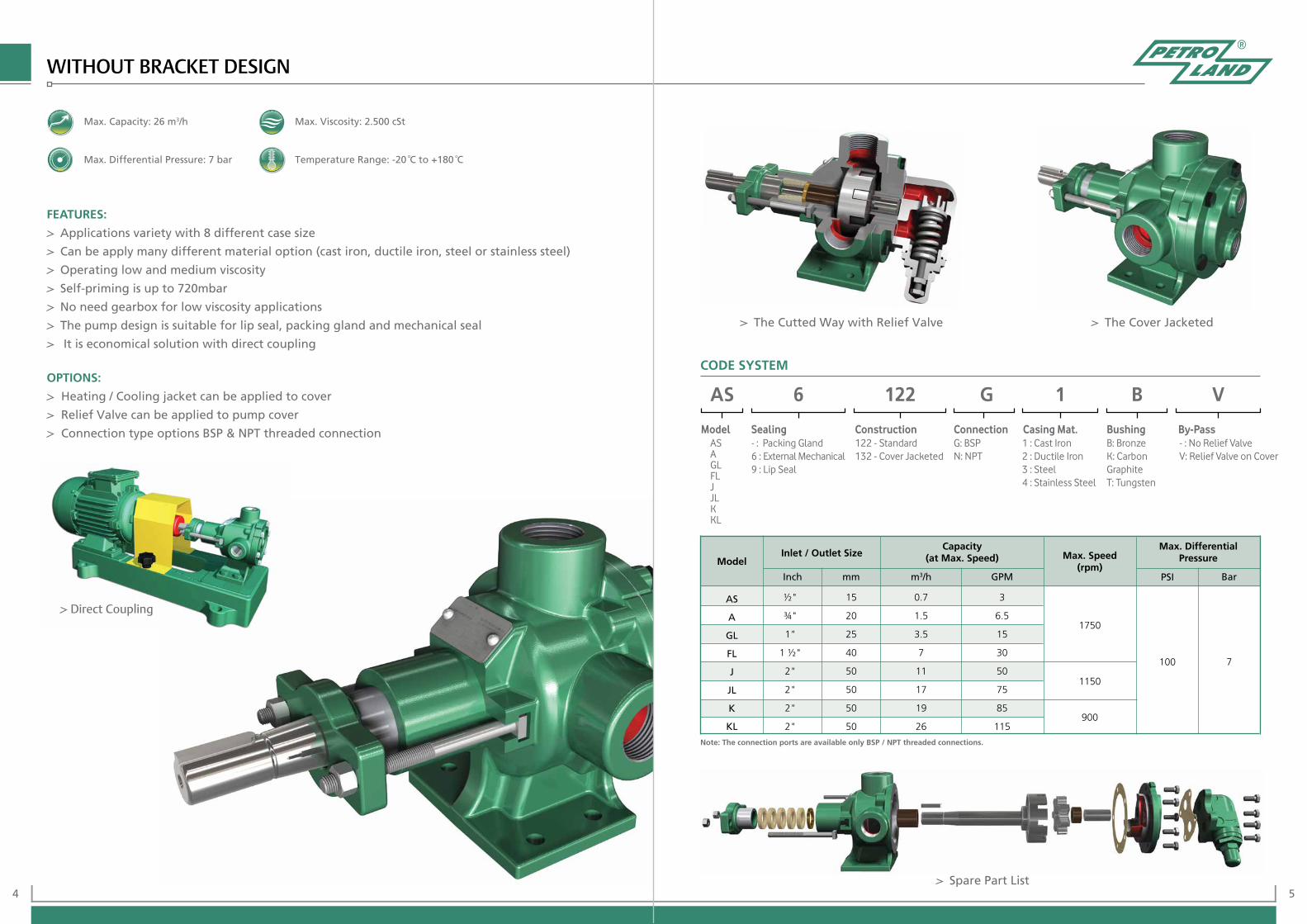
The Cutted Way with Relief Valve The Cover Jacketed
Spare Part List
Note: The connection ports are available only BSP / NPT threaded connections.
Max. Capacity: 26 m3/h
Max. Differential Pressure: 7 bar
Max. Viscosity: 2.500 cSt
Temperature Range: -20 °C to +180 °C
Model
Capacity (at Max. Speed) Max. Speed
(rpm)
Max. Differential PressureInlet / Outlet Size
Inch mm m3/h GPM PSI Bar
AS
A
GL
FL
J
JL
K
KL
½"
¾"
1"
1 ½"
2"
2"
2"
2"
15
20
25
40
50
50
50
50
0.7
1.5
3.5
7
11
17
19
26
3
6.5
15
30
50
75
85
115
1750
1150
900
100 7
ASAGLFLJJLKKL
122 - Standard132 - Cover Jacketed
- : Packing Gland6 : External Mechanical 9 : Lip Seal
1 : Cast Iron2 : Ductile Iron3 : Steel4 : Stainless Steel
G: BSPN: NPT
B: BronzeK: Carbon GraphiteT: Tungsten
- : No Relief ValveV: Relief Valve on Cover
CODE SYSTEM
Model Sealing Construction Connection Casing Mat. Bushing By-Pass
AS 6 122 G 1 B V
WITHOUT BRACKET DESIGN
6 7
FEATURES Applications variety with 19 different case size Can be apply many different material option (cast iron, ductile iron, steel or stainless steel)
Operating wide range of viscosity Self-priming is up to 720mbar The pump design is suitable for every type of seal (Special design, lip seal, packing gland, single mechanical seal, double mechanical seal)
OPTIONS
Heating / Cooling jackets can be applied to cover, case or bracket
Relief Valve can be applied to pump cover
Connection type options, ANSI&DIN Flanged connection or BSP&NPT threaded connection
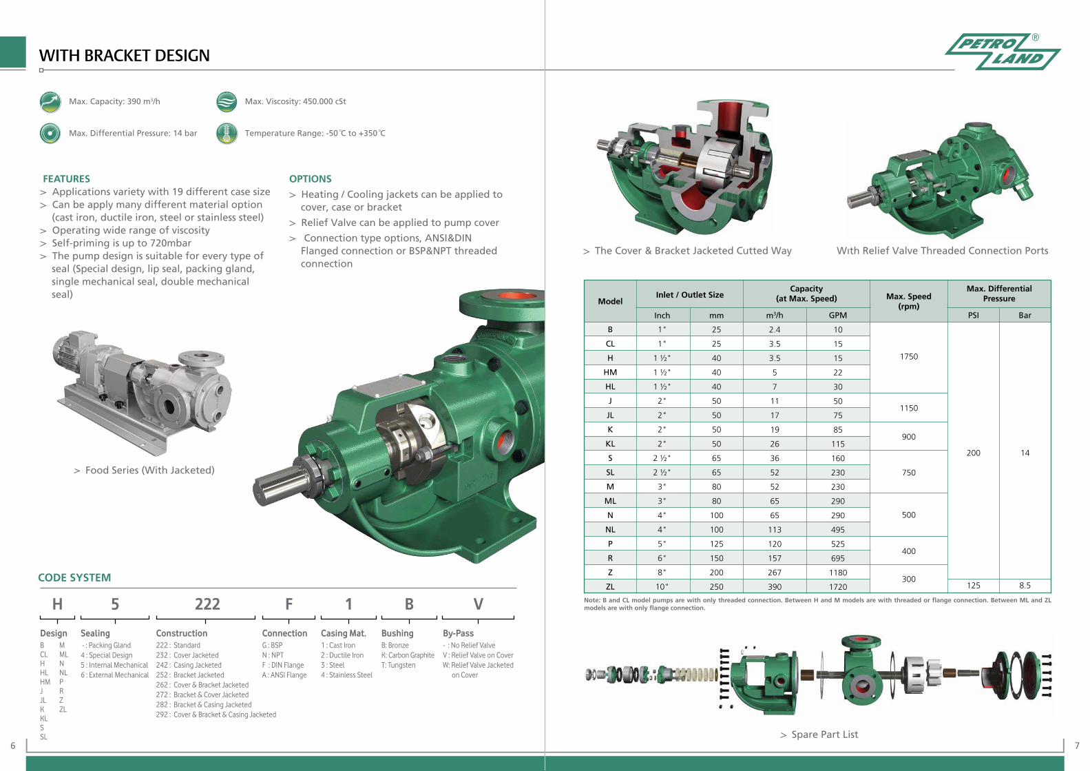
Food Series (With Jacketed)
The Cover & Bracket Jacketed Cutted Way
Spare Part List
Wıth Relief Valve Threaded Connection Ports
Note: B and CL model pumps are with only threaded connection. Between H and M models are with threaded or flange connection. Between ML and ZL models are with only flange connection.
Model
Capacity (at Max. Speed) Max. Speed
(rpm)
Max. Differential Pressure
B
CL
H
HM
HL
J
JL
K
KL
S
SL
M
ML
N
NL
P
R
Z
ZL
1"
1"
1 ½"
1 ½"
1 ½"
2"
2"
2"
2"
2 ½"
2 ½"
3"
3"
4"
4"
5"
6"
8"
10"
25
25
40
40
40
50
50
50
50
65
65
80
80
100
100
125
150
200
250
2.4
3.5
3.5
5
7
11
17
19
26
36
52
52
65
65
113
120
157
267
390
10
15
15
22
30
50
75
85
115
160
230
230
290
290
495
525
695
1180
1720 125
200
750
500
400
3008.5
14
1750
1150
900
Inlet / Outlet Size
Inch mm m3/h GPM PSI Bar
Max. Capacity: 390 m3/h
Max. Differential Pressure: 14 bar
Max. Viscosity: 450.000 cSt
Temperature Range: -50 °C to +350 °C
CODE SYSTEM
H 5 222 F 1 B V
Design Sealing Construction Connection Casing Mat. Bushing By-PassBCLHHLHMJJLKKLSSL
MMLNNLPRZZL
- : Packing Gland4 : Special Design5 : Internal Mechanical6 : External Mechanical
222 : Standard232 : Cover Jacketed242 : Casing Jacketed252 : Bracket Jacketed262 : Cover & Bracket Jacketed272 : Bracket & Cover Jacketed282 : Bracket & Casing Jacketed292 : Cover & Bracket & Casing Jacketed
1 : Cast Iron2 : Ductile Iron3 : Steel4 : Stainless Steel
G : BSPN : NPTF : DIN FlangeA : ANSI Flange
B: BronzeK: Carbon GraphiteT: Tungsten
- : No Relief ValveV : Relief Valve on CoverW: Relief Valve Jacketed on Cover
WITH BRACKET DESIGN

8 9
IN-LINE DESIGN
FEATURES:
Applications variety with 17 different case size
Can be apply many different material option (cast iron, ductile iron, steel or stainless steel)
Operating wide range of viscosity
Self-priming is up to 720mbar
The pump design is suitable for every type of seal (Special design, lip seal, packing gland, single mechanical seal, double mechanical seal)
OPTIONS:
Heating / Cooling jackets can be applied to cover, case or bracket
Relief Valve can be applied to pump cover
Connection type options ANSI&DIN Flanged connection
Spare Part List
Food Series (With Jacketed)
Relief Valve on Cover Cutted Way with Relief Valve on
Casing (with Jacketed)
Note: In-Line design pumps are only with flange connection.
125
200
1150
900
500
300
400
750
8.5
14
Model
Capacity (at Max. Speed) Max. Speed
(rpm)
Max. Differential PressureInlet / Outlet Size
Inch mm m3/h GPM PSI Bar
H
HM
HL
J
JL
K
KL
S
SL
M
ML
N
NL
P
R
Z
ZL
1 ½"
1 ½"
1 ½"
2"
2"
2"
2"
2 ½"
2 ½"
3"
3"
4"
4"
5"
6"
8"
10"
40
40
40
50
50
50
50
65
65
80
80
100
100
125
150
200
250
3.5
5
7
11
17
19
26
36
52
52
65
65
113
120
157
267
390
15
22
30
50
75
85
115
160
230
230
290
290
495
525
695
1180
1720
1750
CODE SYSTEM
H 5 422 F 1 B V
Model Sealing Construction Connection Casing Mat. Bushing By-PassHHMHLJJLKKLSSL
MMLNNLPRZZL
- : Packing Gland4 : Special Design 5 : Internal Mechanical6 : External Mechanical
422 : Standard432 : Cover Jacketed452 : Bracket Jacketed462 : Cover & Bracket Jacketed
1 : Cast Iron2 : Ductile Iron3 : Steel4 : Stainless Steel
F : DIN FlangeA : ANSI Flange
B : BronzeK : Carbon GraphiteT : Tungsten
- : No Relief ValveV : Relief Valve on CoverW: Relief Valve Jacketed on CoverX : Relief Valve on CasingY : Relief Valve Jacketed on Casing
Max. Capacity: 390 m3/h
Max. Differential Pressure: 14 bar
Max. Viscosity: 450.000 cSt
Temperature Range: -50 °C to +350 °C
10 11
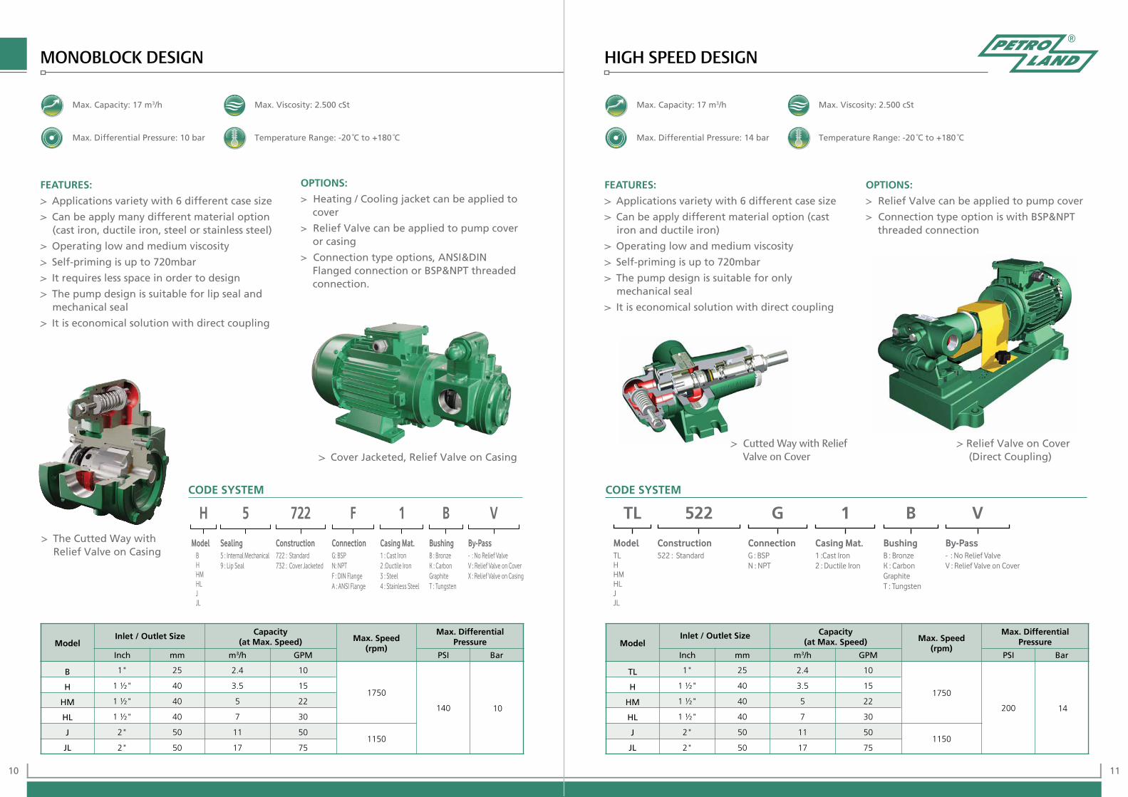
MONOBLOCK DESIGN HIGH SPEED DESIGN
FEATURES:
Applications variety with 6 different case size
Can be apply many different material option (cast iron, ductile iron, steel or stainless steel)
Operating low and medium viscosity
Self-priming is up to 720mbar
It requires less space in order to design
The pump design is suitable for lip seal and mechanical seal
It is economical solution with direct coupling
OPTIONS:
Heating / Cooling jacket can be applied to cover
Relief Valve can be applied to pump cover or casing
Connection type options, ANSI&DIN Flanged connection or BSP&NPT threaded connection.
Cover Jacketed, Relief Valve on Casing
The Cutted Way with Relief Valve on Casing
Relief Valve on Cover (Direct Coupling)
Cutted Way with Relief Valve on Cover
FEATURES:
Applications variety with 6 different case size
Can be apply different material option (cast iron and ductile iron)
Operating low and medium viscosity
Self-priming is up to 720mbar
The pump design is suitable for only mechanical seal
It is economical solution with direct coupling
OPTIONS:
Relief Valve can be applied to pump cover
Connection type option is with BSP&NPT threaded connection
ModelCapacity
(at Max. Speed) Max. Speed (rpm)
Inlet / Outlet Size
B
H
HM
HL
J
JL
1"
1 ½"
1 ½"
1 ½"
2"
2"
25
40
40
40
50
50
2.4
3.5
5
7
11
17
10
15
22
30
50
75
1750
1150
140 10
Max. Capacity: 17 m3/h
Max. Differential Pressure: 10 bar
Max. Viscosity: 2.500 cSt
Temperature Range: -20 °C to +180 °C
Max. Capacity: 17 m3/h
Max. Differential Pressure: 14 bar
Max. Viscosity: 2.500 cSt
Temperature Range: -20 °C to +180 °C
Max. Differential Pressure
Inch mm m3/h GPM PSI BarModel
Capacity (at Max. Speed) Max. Speed
(rpm)
Inlet / Outlet Size
TL
H
HM
HL
J
JL
1"
1 ½"
1 ½"
1 ½"
2"
2"
25
40
40
40
50
50
2.4
3.5
5
7
11
17
10
15
22
30
50
75
1750
1150
200 14
Max. Differential Pressure
Inch mm m3/h GPM PSI Bar
CODE SYSTEMCODE SYSTEM
TL 522 G 1 B V
Model Construction Connection Casing Mat. Bushing By-PassTLHHMHLJJL
522 : Standard 1 :Cast Iron2 : Ductile Iron
G : BSP N : NPT
B : BronzeK : Carbon GraphiteT : Tungsten
- : No Relief ValveV : Relief Valve on Cover
H 5 722 F 1 B V
Model Sealing Construction Connection Casing Mat. Bushing By-PassBHHMHLJJL
5 : Internal Mechanical9 : Lip Seal
722 : Standard732 : Cover Jacketed
1 : Cast Iron2 :Ductile Iron3 : Steel4 : Stainless Steel
G: BSP N: NPT F : DIN FlangeA : ANSI Flange
B : BronzeK : Carbon GraphiteT : Tungsten
- : No Relief ValveV : Relief Valve on CoverX : Relief Valve on Casing
www.petroland.com.tr
PETROLAND POMPA A.Ş.Aydınlı Mh. İstanbul Anadolu Yakası O.S.B.1.Sokak No:7 Tuzla - İstanbul / TURKEYTel: +90 216 593 46 60 (6 line)Fax: +90 216 593 46 66E-mail : [email protected]