pc180 modbus communication manual - profire energy...pc180 modbus communication manual injection...
TRANSCRIPT

PC180 MODBUS COMMUNICATION MANUALI N J E C T I O N M A N A G E M E N T S Y S T E M

The PC180 Chemical Management System (CMS) is an electronic control and monitoring system designed to augment chemical injection pumps found in oil and gas fields. This system helps reduce the amount of waste during the chemical injection process. The PC180 calculates and manages an optimal chemical injection cycle for the desired injection rate.
1 Introduction ...........................................................................................................................................2
1.1 References ........................................................................................................................ 3
2 Controller Setup ....................................................................................................................................4
2.1 Communication Settings ................................................................................................ 5
2.1.1 Station Address ................................................................................................... 5
2.1.2 Protocol ............................................................................................................... 5
2.1.3 Baud Rate ............................................................................................................ 5
2.1.4 Data Bits .............................................................................................................. 6
2.1.5 Parity ................................................................................................................... 6
2.1.6 Stop Bits .............................................................................................................. 6
3 Layer 1 Operation .................................................................................................................................7
4 Layer 2 Operation .................................................................................................................................9
5 Layer 3 Operation ...............................................................................................................................11
5.1 Address Coding .............................................................................................................. 13
6 Application Layer Operation ............................................................................................................15
6.1 Basic Operation .............................................................................................................. 16
6.1.1 History Logs ...................................................................................................... 16
6.1.2 Register Set Access .......................................................................................... 16
6.2 Automatic Dependent Parameter Update ................................................................... 17
6.3 Concurrency Issues ........................................................................................................ 17
6.3.1 Controller Operation ......................................................................................... 17
6.3.2 History Logs ...................................................................................................... 18
6.4 Error Reporting .............................................................................................................. 18
7 Register Formats .................................................................................................................................20
7.1 Date/Time Register ........................................................................................................ 21
7.2 Elapsed Time Register ................................................................................................... 21
7.3 Double Word Register .................................................................................................... 22
8 Register Map .......................................................................................................................................23
8.1 Coils ................................................................................................................................ 24
8.2 Input Discretes ............................................................................................................... 25
8.3 Input Registers ............................................................................................................... 26
9 Acronyms .............................................................................................................................................46

1 | Introduction
1 | Introduction 3
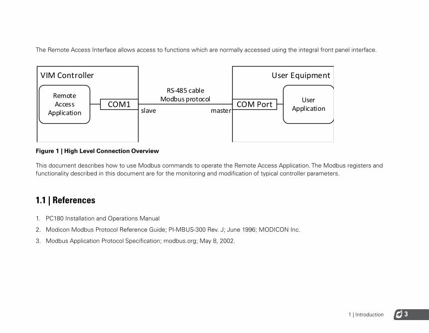
The Remote Access Interface allows access to functions which are normally accessed using the integral front panel interface.
Figure 1 | High Level Connection Overview
This document describes how to use Modbus commands to operate the Remote Access Application. The Modbus registers and functionality described in this document are for the monitoring and modification of typical controller parameters.
1.1 | References
1. PC180 Installation and Operations Manual
2. Modicon Modbus Protocol Reference Guide; PI-MBUS-300 Rev. J; June 1996; MODICON Inc.
3. Modbus Application Protocol Specification; modbus.org; May 8, 2002.
VIM Controller
Remote Access
ApplicationCOM1
User Equipment
COM Port User Applicationslave master
RS-485 cableModbus protocol
2 | Controller Setup
2 | Installation 5
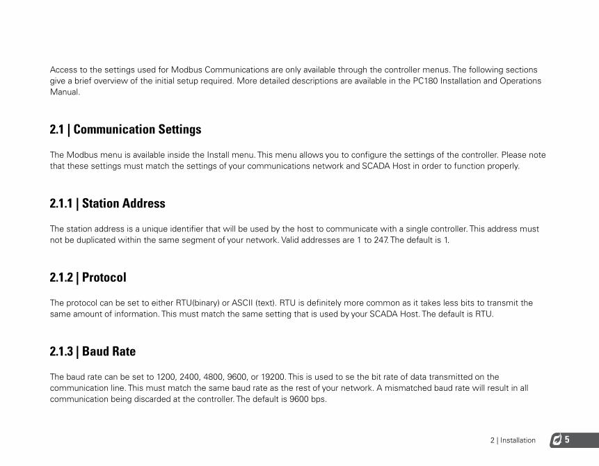
Access to the settings used for Modbus Communications are only available through the controller menus. The following sections give a brief overview of the initial setup required. More detailed descriptions are available in the PC180 Installation and Operations Manual.
2.1 | Communication Settings
The Modbus menu is available inside the Install menu. This menu allows you to configure the settings of the controller. Please note that these settings must match the settings of your communications network and SCADA Host in order to function properly.
2.1.1 | Station Address
The station address is a unique identifier that will be used by the host to communicate with a single controller. This address must not be duplicated within the same segment of your network. Valid addresses are 1 to 247. The default is 1.
2.1.2 | Protocol
The protocol can be set to either RTU(binary) or ASCII (text). RTU is definitely more common as it takes less bits to transmit the same amount of information. This must match the same setting that is used by your SCADA Host. The default is RTU.
2.1.3 | Baud Rate
The baud rate can be set to 1200, 2400, 4800, 9600, or 19200. This is used to se the bit rate of data transmitted on the communication line. This must match the same baud rate as the rest of your network. A mismatched baud rate will result in all communication being discarded at the controller. The default is 9600 bps.
2 | Installation6
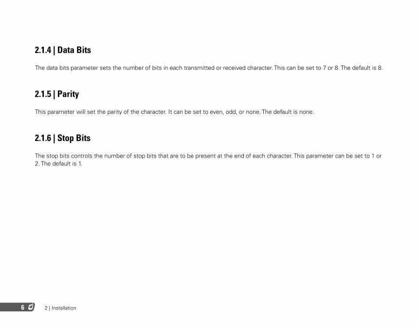
2.1.4 | Data Bits
The data bits parameter sets the number of bits in each transmitted or received character. This can be set to 7 or 8. The default is 8.
2.1.5 | Parity
This parameter will set the parity of the character. It can be set to even, odd, or none. The default is none.
2.1.6 | Stop Bits
The stop bits controls the number of stop bits that are to be present at the end of each character. This parameter can be set to 1 or 2. The default is 1.

3 | Layer 1 Operation
3 | Layer 1 Operation8
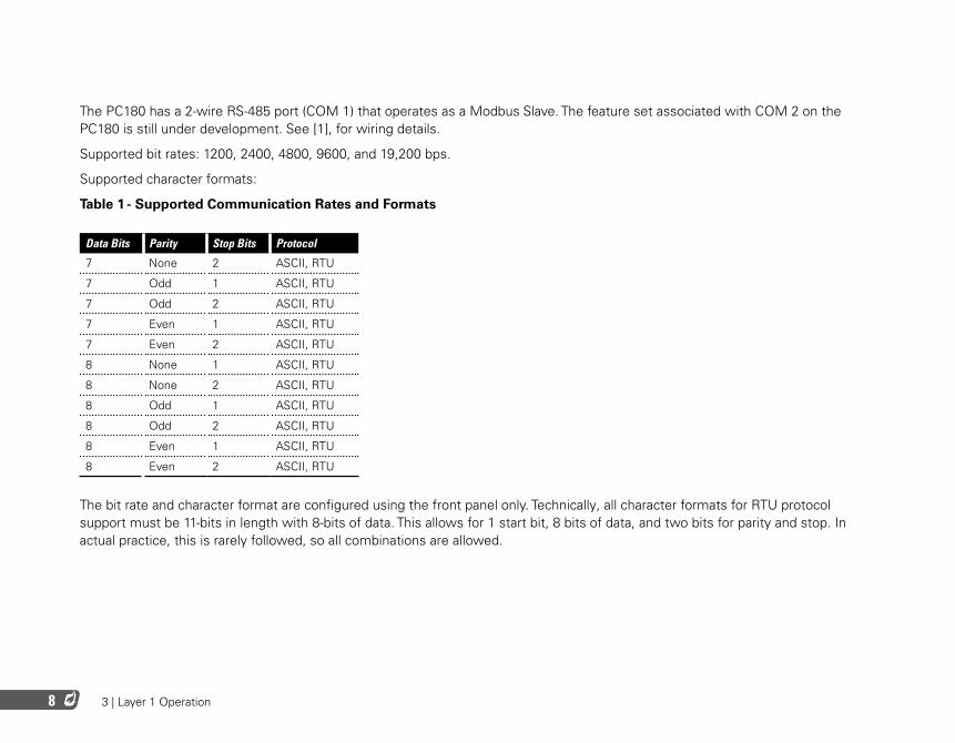
The PC180 has a 2-wire RS-485 port (COM 1) that operates as a Modbus Slave. The feature set associated with COM 2 on the PC180 is still under development. See [1], for wiring details.
Supported bit rates: 1200, 2400, 4800, 9600, and 19,200 bps.
Supported character formats:
Table 1 - Supported Communication Rates and Formats
Data Bits Parity Stop Bits Protocol
7 None 2 ASCII, RTU
7 Odd 1 ASCII, RTU
7 Odd 2 ASCII, RTU
7 Even 1 ASCII, RTU
7 Even 2 ASCII, RTU
8 None 1 ASCII, RTU
8 None 2 ASCII, RTU
8 Odd 1 ASCII, RTU
8 Odd 2 ASCII, RTU
8 Even 1 ASCII, RTU
8 Even 2 ASCII, RTU
The bit rate and character format are configured using the front panel only. Technically, all character formats for RTU protocol support must be 11-bits in length with 8-bits of data. This allows for 1 start bit, 8 bits of data, and two bits for parity and stop. In actual practice, this is rarely followed, so all combinations are allowed.

4 | Layer 2 Operation
4 | Layer 2 Operation10
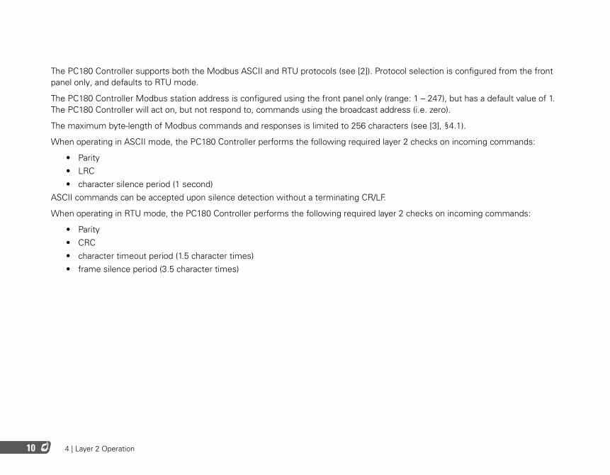
The PC180 Controller supports both the Modbus ASCII and RTU protocols (see [2]). Protocol selection is configured from the front panel only, and defaults to RTU mode.
The PC180 Controller Modbus station address is configured using the front panel only (range: 1 – 247), but has a default value of 1. The PC180 Controller will act on, but not respond to, commands using the broadcast address (i.e. zero).
The maximum byte-length of Modbus commands and responses is limited to 256 characters (see [3], §4.1).
When operating in ASCII mode, the PC180 Controller performs the following required layer 2 checks on incoming commands:
• Parity• LRC• character silence period (1 second)
ASCII commands can be accepted upon silence detection without a terminating CR/LF.
When operating in RTU mode, the PC180 Controller performs the following required layer 2 checks on incoming commands:
• Parity• CRC• character timeout period (1.5 character times)• frame silence period (3.5 character times)

5 | Layer 3 Operation
5 | Layer 3 Operation12
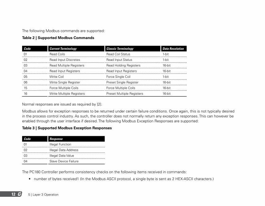
The following Modbus commands are supported:
Table 2 | Supported Modbus Commands
Code Current Terminology Classic Terminology Data Resolution
01 Read Coils Read Coil Status 1-bit
02 Read Input Discretes Read Input Status 1-bit
03 Read Multiple Registers Read Holding Registers 16-bit
04 Read Input Registers Read Input Registers 16-bit
05 Write Coil Force Single Coil 1-bit
06 Write Single Register Preset Single Register 16-bit
15 Force Multiple Coils Force Multiple Coils 16-bit
16 Write Multiple Registers Preset Multiple Registers 16-bit
Normal responses are issued as required by [2].
Modbus allows for exception responses to be returned under certain failure conditions. Once again, this is not typically desired in the process control industry. As such, the controller does not normally return any exception responses. This can however be enabled through the user interface if desired. The following Modbus Exception Responses are supported:
Table 3 | Supported Modbus Exception Responses
Code Response
01 Illegal Function
02 Illegal Data Address
03 Illegal Data Value
04 Slave Device Failure
The PC180 Controller performs consistency checks on the following items received in commands:
• number of bytes received1 (In the Modbus ASCII protocol, a single byte is sent as 2 HEX-ASCII characters.)
5 | Layer 3 Operation 13
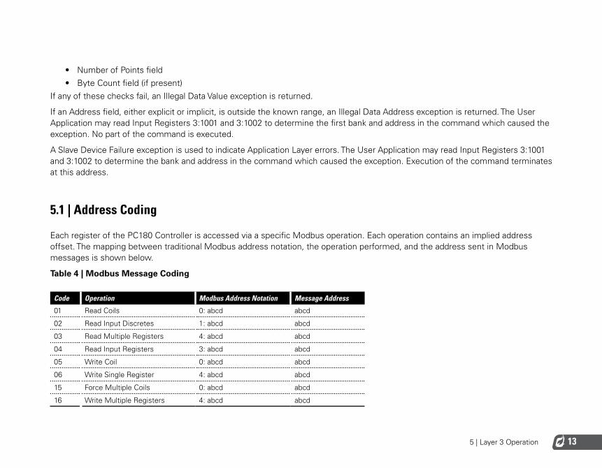
• Number of Points field• Byte Count field (if present)
If any of these checks fail, an Illegal Data Value exception is returned.
If an Address field, either explicit or implicit, is outside the known range, an Illegal Data Address exception is returned. The User Application may read Input Registers 3:1001 and 3:1002 to determine the first bank and address in the command which caused the exception. No part of the command is executed.
A Slave Device Failure exception is used to indicate Application Layer errors. The User Application may read Input Registers 3:1001 and 3:1002 to determine the bank and address in the command which caused the exception. Execution of the command terminates at this address.
5.1 | Address Coding
Each register of the PC180 Controller is accessed via a specific Modbus operation. Each operation contains an implied address offset. The mapping between traditional Modbus address notation, the operation performed, and the address sent in Modbus messages is shown below.
Table 4 | Modbus Message Coding
Code Operation Modbus Address Notation Message Address
01 Read Coils 0: abcd abcd
02 Read Input Discretes 1: abcd abcd
03 Read Multiple Registers 4: abcd abcd
04 Read Input Registers 3: abcd abcd
05 Write Coil 0: abcd abcd
06 Write Single Register 4: abcd abcd
15 Force Multiple Coils 0: abcd abcd
16 Write Multiple Registers 4: abcd abcd
5 | Layer 3 Operation14
For example, accessing register 4:4000 is done via the following operations: ReadMultipleRegisters, WriteSingleRegister, and WriteMultipleRegisters. All of these operations use the address value 4000. Accessing register 0:4000 is done with the following operations: ReadCoils and WriteCoils. These two operations also use the address value 4000, but access a different register.

6 | Application Layer Operation
6 | Application Layer Operation16
6.1 | Basic Operation
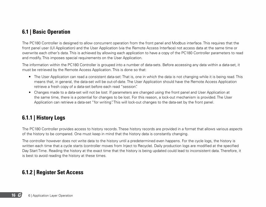
The PC180 Controller is designed to allow concurrent operation from the front panel and Modbus interface. This requires that the front panel user (UI Application) and the User Application (via the Remote Access Interface) not access data at the same time or overwrite each other’s data. This is achieved by allowing each application to have a copy of the PC180 Controller parameters to read and modify. This imposes special requirements on the User Application.
The information within the PC180 Controller is grouped into a number of data-sets. Before accessing any data within a data-set, it must be retrieved by the Remote Access Application. This is done so that:
• The User Application can read a consistent data-set: That is, one in which the data is not changing while it is being read. This means that, in general, the data-set will be out-of-date. The User Application should have the Remote Access Application retrieve a fresh copy of a data-set before each read “session”.
• Changes made to a data-set will not be lost: If parameters are changed using the front panel and User Application at the same time, there is a potential for changes to be lost. For this reason, a lock-out mechanism is provided. The User Application can retrieve a data-set “for writing”. This will lock-out changes to the data-set by the front panel.
6.1.1 | History Logs
The PC180 Controller provides access to history records. These history records are provided in a format that allows various aspects of the history to be compared. One must keep in mind that the history data is constantly changing.
The controller however does not write data to the history until a predetermined even happens. For the cycle logs, the history is written each time that a cycle starts (controller moves from Inject to Recycle). Daily production logs are modified at the specified Day Start Time. Reading the history at the exact time that the history is being updated could lead to inconsistent data. Therefore, it is best to avoid reading the history at these times.
6.1.2 | Register Set Access
6 | Application Layer Operation 17
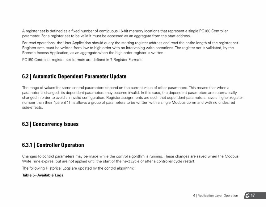
A register set is defined as a fixed number of contiguous 16-bit memory locations that represent a single PC180 Controller parameter. For a register set to be valid it must be accessed as an aggregate from the start address.
For read operations, the User Application should query the starting register address and read the entire length of the register set. Register sets must be written from low to high order with no intervening write operations. The register set is validated, by the Remote Access Application, as an aggregate when the high order register is written.
PC180 Controller register set formats are defined in 7 Register Formats
6.2 | Automatic Dependent Parameter Update
The range of values for some control parameters depend on the current value of other parameters. This means that when a parameter is changed, its dependent parameters may become invalid. In this case, the dependent parameters are automatically changed in order to avoid an invalid configuration. Register assignments are such that dependent parameters have a higher register number than their “parent”. This allows a group of parameters to be written with a single Modbus command with no undesired side-effects.
6.3 | Concurrency Issues
6.3.1 | Controller Operation
Changes to control parameters may be made while the control algorithm is running. These changes are saved when the Modbus Write Time expires, but are not applied until the start of the next cycle or after a controller cycle restart.
The following Historical Logs are updated by the control algorithm:
Table 5 - Available Logs
6 | Application Layer Operation18
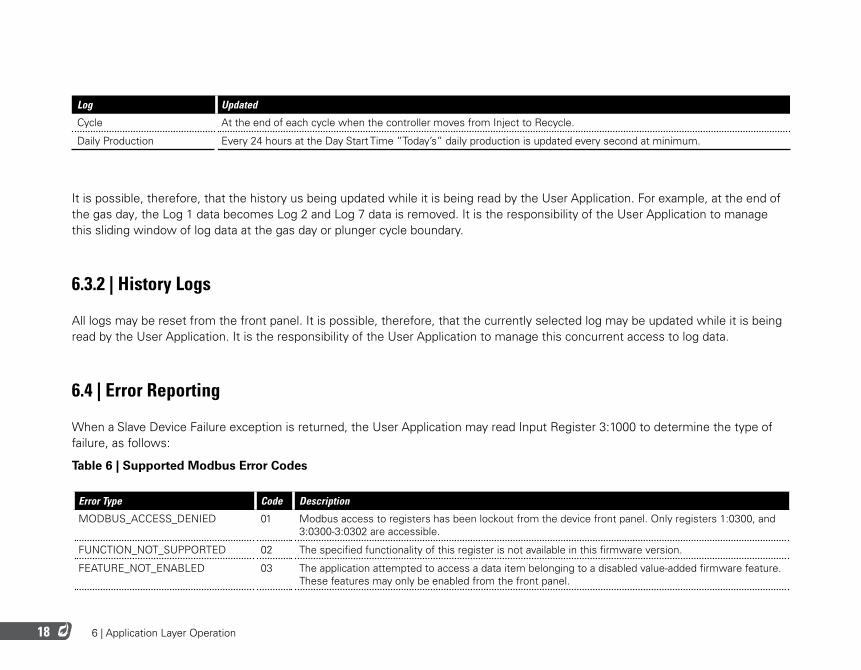
Log Updated
Cycle At the end of each cycle when the controller moves from Inject to Recycle.
Daily Production Every 24 hours at the Day Start Time ”Today’s” daily production is updated every second at minimum.
It is possible, therefore, that the history us being updated while it is being read by the User Application. For example, at the end of the gas day, the Log 1 data becomes Log 2 and Log 7 data is removed. It is the responsibility of the User Application to manage this sliding window of log data at the gas day or plunger cycle boundary.
6.3.2 | History Logs
All logs may be reset from the front panel. It is possible, therefore, that the currently selected log may be updated while it is being read by the User Application. It is the responsibility of the User Application to manage this concurrent access to log data.
6.4 | Error Reporting
When a Slave Device Failure exception is returned, the User Application may read Input Register 3:1000 to determine the type of failure, as follows:
Table 6 | Supported Modbus Error Codes
Error Type Code Description
MODBUS_ACCESS_DENIED 01 Modbus access to registers has been lockout from the device front panel. Only registers 1:0300, and 3:0300-3:0302 are accessible.
FUNCTION_NOT_SUPPORTED 02 The specified functionality of this register is not available in this firmware version.
FEATURE_NOT_ENABLED 03 The application attempted to access a data item belonging to a disabled value-added firmware feature. These features may only be enabled from the front panel.
6 | Application Layer Operation 19
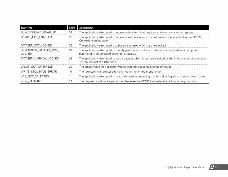
Error Type Code Description
FUNCTION_NOT_ENABLED 04 The application attempted to access a data item that requires activation via another register.
DEVICE_NOT_ENABLED 05 The application attempted to access a real device which is not present (i.e. enabled) in the PC180 Controller configuration.
DATASET_NOT_LOCKED 06 The application attempted to write to a dataset which was not locked.
DEPENDENT_DATASET_NOT_LOCKED
07 The application attempted to modify parameter in a locked dataset that required an auto update parameter in an unlocked dependent dataset.
DATASET_ALREADY_LOCKED 08 The application attempted to lock a dataset which is currently locked by the integral control panel user. Try the request at a later time.
VALUE_OUT_OF_RANGE 09 The preset value for a register was outside the acceptable range of values.
WRITE_SEQUENCE_ERROR 10 The registers in a register set were not written in the proper order.
LOG_NOT_SELECTED 11 The application attempted to read a data value belonging to a historical log which has not been loaded.
LOW_BATTERY 12 The request could not be performed because the PC180 Controller is in a low battery condition.

7 | Register Formats
7 | Register Formats 21
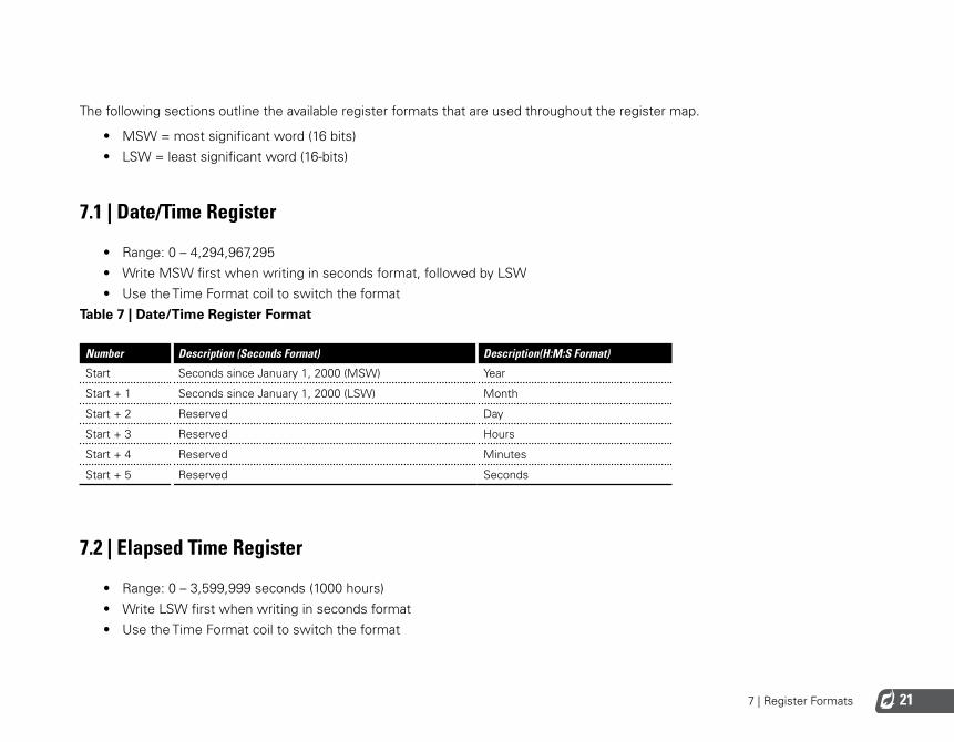
The following sections outline the available register formats that are used throughout the register map.
• MSW = most significant word (16 bits)• LSW = least significant word (16-bits)
7.1 | Date/Time Register
• Range: 0 – 4,294,967,295• Write MSW first when writing in seconds format, followed by LSW• Use the Time Format coil to switch the format
Table 7 | Date/Time Register Format
Number Description (Seconds Format) Description(H:M:S Format)
Start Seconds since January 1, 2000 (MSW) Year
Start + 1 Seconds since January 1, 2000 (LSW) Month
Start + 2 Reserved Day
Start + 3 Reserved Hours
Start + 4 Reserved Minutes
Start + 5 Reserved Seconds
7.2 | Elapsed Time Register
• Range: 0 – 3,599,999 seconds (1000 hours)• Write LSW first when writing in seconds format• Use the Time Format coil to switch the format
7 | Register Formats22
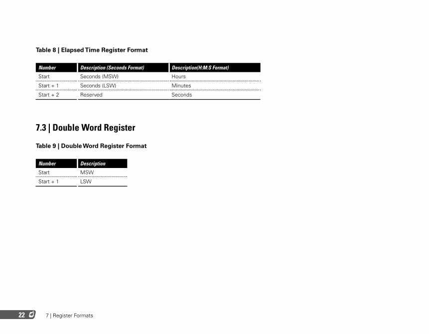
Table 8 | Elapsed Time Register Format
Number Description (Seconds Format) Description(H:M:S Format)
Start Seconds (MSW) Hours
Start + 1 Seconds (LSW) Minutes
Start + 2 Reserved Seconds
7.3 | Double Word Register
Table 9 | Double Word Register Format
Number Description
Start MSW
Start + 1 LSW

8 | Register Map
8 | Register Map24
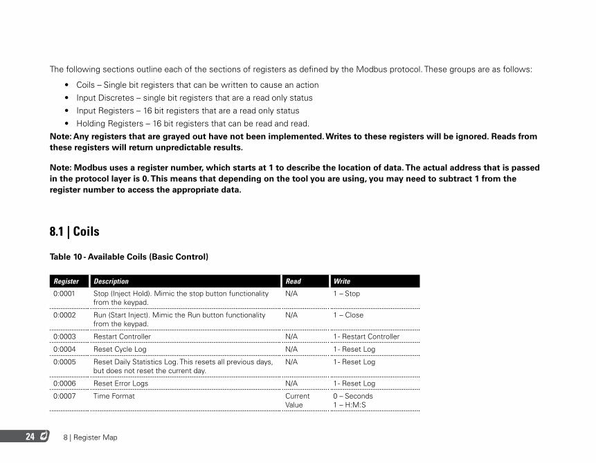
The following sections outline each of the sections of registers as defined by the Modbus protocol. These groups are as follows:
• Coils – Single bit registers that can be written to cause an action• Input Discretes – single bit registers that are a read only status• Input Registers – 16 bit registers that are a read only status• Holding Registers – 16 bit registers that can be read and read.
Note: Any registers that are grayed out have not been implemented. Writes to these registers will be ignored. Reads from these registers will return unpredictable results.
Note: Modbus uses a register number, which starts at 1 to describe the location of data. The actual address that is passed in the protocol layer is 0. This means that depending on the tool you are using, you may need to subtract 1 from the register number to access the appropriate data.
8.1 | Coils
Table 10 - Available Coils (Basic Control)
Register Description Read Write
0:0001 Stop (Inject Hold). Mimic the stop button functionality from the keypad.
N/A 1 – Stop
0:0002 Run (Start Inject). Mimic the Run button functionality from the keypad.
N/A 1 – Close
0:0003 Restart Controller N/A 1 - Restart Controller
0:0004 Reset Cycle Log N/A 1 - Reset Log
0:0005 Reset Daily Statistics Log. This resets all previous days, but does not reset the current day.
N/A 1 - Reset Log
0:0006 Reset Error Logs N/A 1 - Reset Log
0:0007 Time Format Current Value
0 – Seconds 1 – H:M:S
8 | Register Map 25
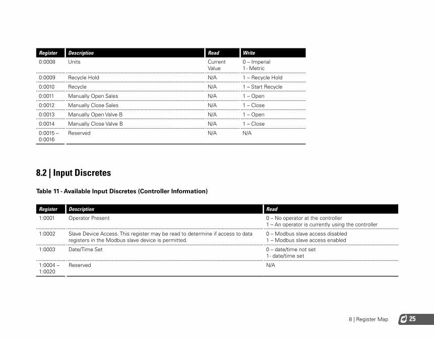
Register Description Read Write
0:0008 Units Current Value
0 – Imperial 1 - Metric
0:0009 Recycle Hold N/A 1 – Recycle Hold
0:0010 Recycle N/A 1 – Start Recycle
0:0011 Manually Open Sales N/A 1 – Open
0:0012 Manually Close Sales N/A 1 – Close
0:0013 Manually Open Valve B N/A 1 – Open
0:0014 Manually Close Valve B N/A 1 – Close
0:0015 – 0:0016
Reserved N/A N/A
8.2 | Input Discretes
Table 11 - Available Input Discretes (Controller Information)
Register Description Read
1:0001 Operator Present 0 – No operator at the controller 1 – An operator is currently using the controller
1:0002 Slave Device Access. This register may be read to determine if access to data registers in the Modbus slave device is permitted.
0 – Modbus slave access disabled 1 – Modbus slave access enabled
1:0003 Date/Time Set 0 – date/time not set 1 - date/time set
1:0004 – 1:0020
Reserved N/A
8 | Register Map26
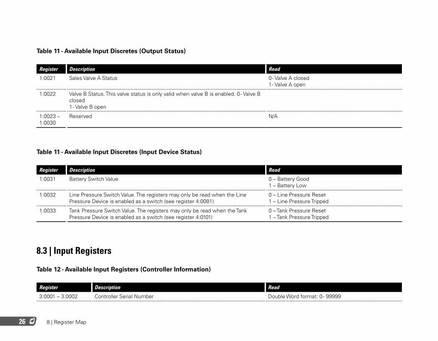
Table 11 - Available Input Discretes (Output Status)
Register Description Read
1:0021 Sales Valve A Status 0 - Valve A closed 1 - Valve A open
1:0022 Valve B Status. This valve status is only valid when valve B is enabled. 0 - Valve B closed 1 - Valve B open
1:0023 – 1:0030
Reserved N/A
Table 11 - Available Input Discretes (Input Device Status)
Register Description Read
1:0031 Battery Switch Value 0 – Battery Good 1 – Battery Low
1:0032 Line Pressure Switch Value. The registers may only be read when the Line Pressure Device is enabled as a switch (see register 4:0081)
0 – Line Pressure Reset 1 – Line Pressure Tripped
1:0033 Tank Pressure Switch Value. The registers may only be read when the Tank Pressure Device is enabled as a switch (see register 4:0101)
0 – Tank Pressure Reset 1 – Tank Pressure Tripped
8.3 | Input Registers
Table 12 - Available Input Registers (Controller Information)
Register Description Read
3:0001 – 3:0002 Controller Serial Number Double Word format: 0 - 99999
8 | Register Map 27
Register Description Read
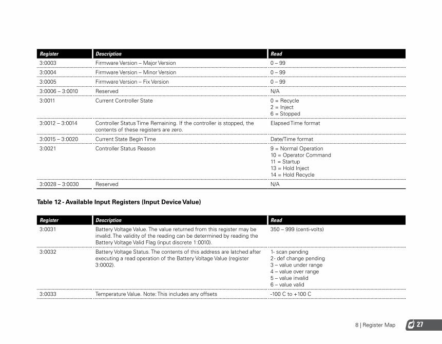
3:0003 Firmware Version – Major Version 0 – 99
3:0004 Firmware Version – Minor Version 0 – 99
3:0005 Firmware Version – Fix Version 0 – 99
3:0006 – 3:0010 Reserved N/A
3:0011 Current Controller State 0 = Recycle 2 = Inject 6 = Stopped
3:0012 – 3:0014 Controller Status Time Remaining. If the controller is stopped, the contents of these registers are zero.
Elapsed Time format
3:0015 – 3:0020 Current State Begin Time Date/Time format
3:0021 Controller Status Reason 9 = Normal Operation 10 = Operator Command 11 = Startup 13 = Hold Inject 14 = Hold Recycle
3:0028 – 3:0030 Reserved N/A
Table 12 - Available Input Registers (Input Device Value)
Register Description Read
3:0031 Battery Voltage Value. The value returned from this register may be invalid. The validity of the reading can be determined by reading the Battery Voltage Valid Flag (input discrete 1:0010).
350 – 999 (centi-volts)
3:0032 Battery Voltage Status. The contents of this address are latched after executing a read operation of the Battery Voltage Value (register 3:0002).
1- scan pending 2 - def change pending 3 – value under range 4 – value over range 5 – value invalid 6 – value valid
3:0033 Temperature Value. Note: This includes any offsets -100 C to +100 C
8 | Register Map28
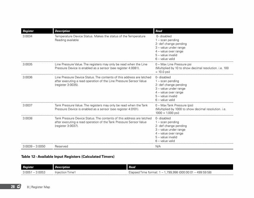
Register Description Read
3:0034 Temperature Device Status. Makes the status of the Temperature Reading available
0 - disabled 1 – scan pending 2 - def change pending 3 – value under range 4 – value over range 5 – value invalid 6 – value valid
3:0035 Line Pressure Value. The registers may only be read when the Line Pressure Device is enabled as a sensor (see register 4:0081).
0 – Max Line Pressure psi (Multiplied by 10 to show decimal resolution. i.e. 100 = 10.0 psi)
3:0036 Line Pressure Device Status. The contents of this address are latched after executing a read operation of the Line Pressure Sensor Value (register 3:0035).
0 - disabled 1 – scan pending 2 - def change pending 3 – value under range 4 – value over range 5 – value invalid 6 – value valid
3:0037 Tank Pressure Value. The registers may only be read when the Tank Pressure Device is enabled as a sensor (see register 4:0101).
0 – Max Tank Pressure (psi) (Multiplied by 1000 to show decimal resolution. i.e. 1000 = 1.000 psi)
3:0038 Tank Pressure Device Status. The contents of this address are latched after executing a read operation of the Tank Pressure Sensor Value (register 3:0037).
0 - disabled 1 – scan pending 2 - def change pending 3 – value under range 4 – value over range 5 – value invalid 6 – value valid
3:0039 – 3:0050 Reserved N/A
Table 12 - Available Input Registers (Calculated Timers)
Register Description Read
3:0051 – 3:0053 Injection Time1 Elapsed Time format: 1 – 1,799,998 (000:00:01 – 499:59:58)
8 | Register Map 29
Register Description Read
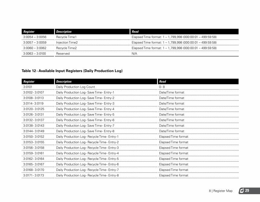
3:0054 – 3:0056 Recycle Time1 Elapsed Time format: 1 – 1,799,998 (000:00:01 – 499:59:58)
3:0057 – 3:0059 Injection Time2 Elapsed Time format: 1 – 1,799,998 (000:00:01 – 499:59:58)
3:0060 – 3:0062 Recycle Time2 Elapsed Time format: 1 – 1,799,998 (000:00:01 – 499:59:58)
3:0063 – 3:0100 Reserved N/A
Table 12 - Available Input Registers (Daily Production Log)
Register Description Read
3:0101 Daily Production Log Count 0 - 8
3:0102 - 3:0107 Daily Production Log - Save Time - Entry -1 Date/Time format
3:0108 - 3:0113 Daily Production Log - Save Time - Entry -2 Date/Time format
3:0114 - 3:0119 Daily Production Log - Save Time - Entry -3 Date/Time format
3:0120 - 3:0125 Daily Production Log - Save Time - Entry -4 Date/Time format
3:0126 - 3:0131 Daily Production Log - Save Time - Entry -5 Date/Time format
3:0132 - 3:0137 Daily Production Log - Save Time - Entry -6 Date/Time format
3:0138 - 3:0143 Daily Production Log - Save Time - Entry -7 Date/Time format
3:0144 - 3:0149 Daily Production Log - Save Time - Entry -8 Date/Time format
3:0150 - 3:0152 Daily Production Log - Recycle Time - Entry -1 Elapsed Time format
3:0153 - 3:0155 Daily Production Log - Recycle Time - Entry -2 Elapsed Time format
3:0156 - 3:0158 Daily Production Log - Recycle Time - Entry -3 Elapsed Time format
3:0159 - 3:0161 Daily Production Log - Recycle Time - Entry -4 Elapsed Time format
3:0162 - 3:0164 Daily Production Log - Recycle Time - Entry -5 Elapsed Time format
3:0165 - 3:0167 Daily Production Log - Recycle Time - Entry -6 Elapsed Time format
3:0168 - 3:0170 Daily Production Log - Recycle Time - Entry -7 Elapsed Time format
3:0171 - 3:0173 Daily Production Log - Recycle Time - Entry -8 Elapsed Time format
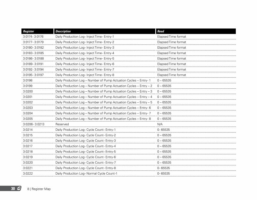
8 | Register Map30
Register Description Read
3:0174 - 3:0176 Daily Production Log - Inject Time - Entry -1 Elapsed Time format
3:0177 - 3:0179 Daily Production Log - Inject Time - Entry -2 Elapsed Time format
3:0180 - 3:0182 Daily Production Log - Inject Time - Entry -3 Elapsed Time format
3:0183 - 3:0185 Daily Production Log - Inject Time - Entry -4 Elapsed Time format
3:0186 - 3:0188 Daily Production Log - Inject Time - Entry -5 Elapsed Time format
3:0189 - 3:0191 Daily Production Log - Inject Time - Entry -6 Elapsed Time format
3:0192 - 3:0194 Daily Production Log - Inject Time - Entry -7 Elapsed Time format
3:0195 - 3:0197 Daily Production Log - Inject Time - Entry -8 Elapsed Time format
3:0198 Daily Production Log – Number of Pump Actuation Cycles – Entry - 1 0 – 65535
3:0199 Daily Production Log – Number of Pump Actuation Cycles – Entry – 2 0 – 65535
3:0200 Daily Production Log – Number of Pump Actuation Cycles – Entry – 3 0 – 65535
3:0201 Daily Production Log – Number of Pump Actuation Cycles – Entry – 4 0 – 65535
3:0202 Daily Production Log – Number of Pump Actuation Cycles – Entry – 5 0 – 65535
3:0203 Daily Production Log – Number of Pump Actuation Cycles – Entry - 6 0 – 65535
3:0204 Daily Production Log – Number of Pump Actuation Cycles – Entry - 7 0 – 65535
3:0205 Daily Production Log – Number of Pump Actuation Cycles – Entry - 8 0 – 65535
3:0206 - 3:0213 Reserved N/A
3:0214 Daily Production Log - Cycle Count - Entry -1 0 - 65535
3:0215 Daily Production Log - Cycle Count - Entry -2 0 – 65535
3:0216 Daily Production Log - Cycle Count - Entry -3 0 – 65535
3:0217 Daily Production Log - Cycle Count - Entry -4 0 – 65535
3:0218 Daily Production Log - Cycle Count - Entry -5 0 – 65535
3:0219 Daily Production Log - Cycle Count - Entry -6 0 – 65535
3:0220 Daily Production Log - Cycle Count - Entry -7 0 – 65535
3:0221 Daily Production Log - Cycle Count - Entry -8 0 - 65535
3:0222 Daily Production Log - Normal Cycle Count -1 0 - 65535
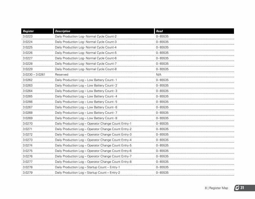
8 | Register Map 31
Register Description Read
3:0223 Daily Production Log - Normal Cycle Count -2 0 - 65535
3:0224 Daily Production Log - Normal Cycle Count -3 0 - 65535
3:0225 Daily Production Log - Normal Cycle Count -4 0 - 65535
3:0226 Daily Production Log - Normal Cycle Count -5 0 - 65535
3:0227 Daily Production Log - Normal Cycle Count -6 0 - 65535
3:0228 Daily Production Log - Normal Cycle Count -7 0 - 65535
3:0229 Daily Production Log - Normal Cycle Count -8 0 - 65535
3:0230 – 3:0261 Reserved N/A
3:0262 Daily Production Log – Low Battery Count - 1 0 - 65535
3:0263 Daily Production Log – Low Battery Count - 2 0 - 65535
3:0264 Daily Production Log – Low Battery Count - 3 0 - 65535
3:0265 Daily Production Log – Low Battery Count - 4 0 - 65535
3:0266 Daily Production Log – Low Battery Count - 5 0 - 65535
3:0267 Daily Production Log – Low Battery Count - 6 0 - 65535
3:0268 Daily Production Log – Low Battery Count - 7 0 - 65535
3:0269 Daily Production Log – Low Battery Count - 8 0 - 65535
3:0270 Daily Production Log – Operator Change Count Entry -1 0 - 65535
3:0271 Daily Production Log – Operator Change Count Entry -2 0 - 65535
3:0272 Daily Production Log – Operator Change Count Entry -3 0 - 65535
3:0273 Daily Production Log – Operator Change Count Entry -4 0 - 65535
3:0274 Daily Production Log – Operator Change Count Entry -5 0 - 65535
3:0275 Daily Production Log – Operator Change Count Entry -6 0 - 65535
3:0276 Daily Production Log – Operator Change Count Entry -7 0 - 65535
3:0277 Daily Production Log – Operator Change Count Entry -8 0 - 65535
3:0278 Daily Production Log – Startup Count – Entry -1 0 - 65535
3:0279 Daily Production Log – Startup Count – Entry -2 0 - 65535
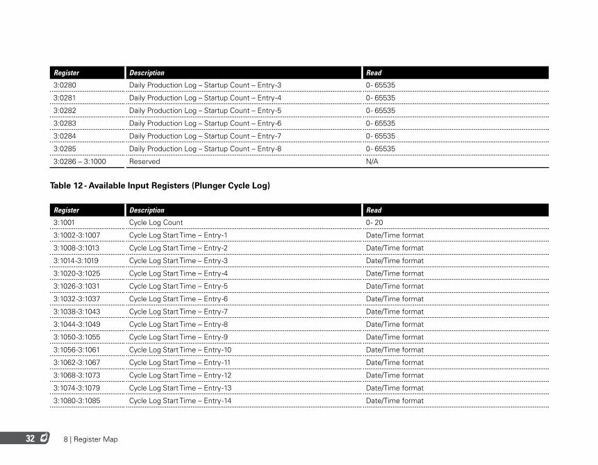
8 | Register Map32
Register Description Read
3:0280 Daily Production Log – Startup Count – Entry -3 0 - 65535
3:0281 Daily Production Log – Startup Count – Entry -4 0 - 65535
3:0282 Daily Production Log – Startup Count – Entry -5 0 - 65535
3:0283 Daily Production Log – Startup Count – Entry -6 0 - 65535
3:0284 Daily Production Log – Startup Count – Entry -7 0 - 65535
3:0285 Daily Production Log – Startup Count – Entry -8 0 - 65535
3:0286 – 3:1000 Reserved N/A
Table 12 - Available Input Registers (Plunger Cycle Log)
Register Description Read
3:1001 Cycle Log Count 0 - 20
3:1002 -3:1007 Cycle Log Start Time – Entry -1 Date/Time format
3:1008 -3:1013 Cycle Log Start Time – Entry -2 Date/Time format
3:1014 -3:1019 Cycle Log Start Time – Entry -3 Date/Time format
3:1020 -3:1025 Cycle Log Start Time – Entry -4 Date/Time format
3:1026 -3:1031 Cycle Log Start Time – Entry -5 Date/Time format
3:1032 -3:1037 Cycle Log Start Time – Entry -6 Date/Time format
3:1038 -3:1043 Cycle Log Start Time – Entry -7 Date/Time format
3:1044 -3:1049 Cycle Log Start Time – Entry -8 Date/Time format
3:1050 -3:1055 Cycle Log Start Time – Entry -9 Date/Time format
3:1056 -3:1061 Cycle Log Start Time – Entry -10 Date/Time format
3:1062 -3:1067 Cycle Log Start Time – Entry -11 Date/Time format
3:1068 -3:1073 Cycle Log Start Time – Entry -12 Date/Time format
3:1074 -3:1079 Cycle Log Start Time – Entry -13 Date/Time format
3:1080 -3:1085 Cycle Log Start Time – Entry -14 Date/Time format
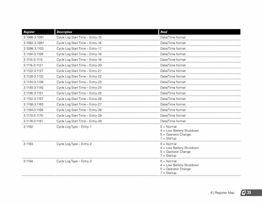
8 | Register Map 33
Register Description Read
3:1086 -3:1091 Cycle Log Start Time – Entry -15 Date/Time format
3:1092 -3:1097 Cycle Log Start Time – Entry -16 Date/Time format
3:1098 -3:1103 Cycle Log Start Time – Entry -17 Date/Time format
3:1104 -3:1109 Cycle Log Start Time – Entry -18 Date/Time format
3:1110 -3:1115 Cycle Log Start Time – Entry -19 Date/Time format
3:1116 -3:1121 Cycle Log Start Time – Entry -20 Date/Time format
3:1122 -3:1127 Cycle Log Start Time – Entry -21 Date/Time format
3:1128 -3:1133 Cycle Log Start Time – Entry -22 Date/Time format
3:1134 -3:1139 Cycle Log Start Time – Entry -23 Date/Time format
3:1140 -3:1145 Cycle Log Start Time – Entry -24 Date/Time format
3:1146 -3:1151 Cycle Log Start Time – Entry -25 Date/Time format
3:1152 -3:1157 Cycle Log Start Time – Entry -26 Date/Time format
3:1158 -3:1163 Cycle Log Start Time – Entry -27 Date/Time format
3:1164-3:1169 Cycle Log Start Time – Entry -28 Date/Time format
3:1170-3:1175 Cycle Log Start Time – Entry -29 Date/Time format
3:1176-3:1181 Cycle Log Start Time – Entry -30 Date/Time format
3:1182 Cycle Log Type – Entry -1 0 = Normal 4 = Low Battery Shutdown 5 = Operator Change 7 = Startup
3:1183 Cycle Log Type – Entry -2 0 = Normal 4 = Low Battery Shutdown 5 = Operator Change 7 = Startup
3:1184 Cycle Log Type – Entry -3 0 = Normal 4 = Low Battery Shutdown 5 = Operator Change 7 = Startup
8 | Register Map34
Register Description Read
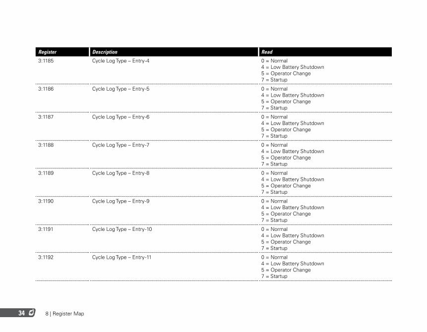
3:1185 Cycle Log Type – Entry -4 0 = Normal 4 = Low Battery Shutdown 5 = Operator Change 7 = Startup
3:1186 Cycle Log Type – Entry -5 0 = Normal 4 = Low Battery Shutdown 5 = Operator Change 7 = Startup
3:1187 Cycle Log Type – Entry -6 0 = Normal 4 = Low Battery Shutdown 5 = Operator Change 7 = Startup
3:1188 Cycle Log Type – Entry -7 0 = Normal 4 = Low Battery Shutdown 5 = Operator Change 7 = Startup
3:1189 Cycle Log Type – Entry -8 0 = Normal 4 = Low Battery Shutdown 5 = Operator Change 7 = Startup
3:1190 Cycle Log Type – Entry -9 0 = Normal 4 = Low Battery Shutdown 5 = Operator Change 7 = Startup
3:1191 Cycle Log Type – Entry -10 0 = Normal 4 = Low Battery Shutdown 5 = Operator Change 7 = Startup
3:1192 Cycle Log Type – Entry -11 0 = Normal 4 = Low Battery Shutdown 5 = Operator Change 7 = Startup
8 | Register Map 35
Register Description Read
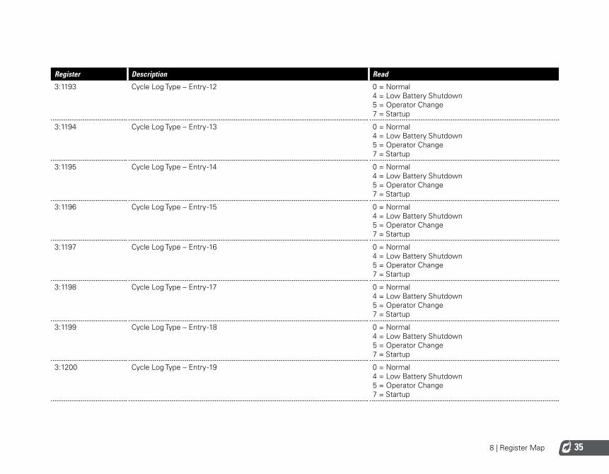
3:1193 Cycle Log Type – Entry -12 0 = Normal 4 = Low Battery Shutdown 5 = Operator Change 7 = Startup
3:1194 Cycle Log Type – Entry -13 0 = Normal 4 = Low Battery Shutdown 5 = Operator Change 7 = Startup
3:1195 Cycle Log Type – Entry -14 0 = Normal 4 = Low Battery Shutdown 5 = Operator Change 7 = Startup
3:1196 Cycle Log Type – Entry -15 0 = Normal 4 = Low Battery Shutdown 5 = Operator Change 7 = Startup
3:1197 Cycle Log Type – Entry -16 0 = Normal 4 = Low Battery Shutdown 5 = Operator Change 7 = Startup
3:1198 Cycle Log Type – Entry -17 0 = Normal 4 = Low Battery Shutdown 5 = Operator Change 7 = Startup
3:1199 Cycle Log Type – Entry -18 0 = Normal 4 = Low Battery Shutdown 5 = Operator Change 7 = Startup
3:1200 Cycle Log Type – Entry -19 0 = Normal 4 = Low Battery Shutdown 5 = Operator Change 7 = Startup

8 | Register Map36
Register Description Read
3:1201 Cycle Log Type – Entry -20 0 = Normal 4 = Low Battery Shutdown 5 = Operator Change 7 = Startup
3:1202 Cycle Log Type – Entry -21 0 = Normal 4 = Low Battery Shutdown 5 = Operator Change 7 = Startup
3:1203 Cycle Log Type – Entry -22 0 = Normal 4 = Low Battery Shutdown 5 = Operator Change 7 = Startup
3:1204 Cycle Log Type – Entry -23 0 = Normal 4 = Low Battery Shutdown 5 = Operator Change 7 = Startup
3:1205 Cycle Log Type – Entry -24 0 = Normal 4 = Low Battery Shutdown 5 = Operator Change 7 = Startup
3:1206 Cycle Log Type – Entry -25 0 = Normal 4 = Low Battery Shutdown 5 = Operator Change 7 = Startup
3:1207 Cycle Log Type – Entry -26 0 = Normal 4 = Low Battery Shutdown 5 = Operator Change 7 = Startup
3:1208 Cycle Log Type – Entry -27 0 = Normal 4 = Low Battery Shutdown 5 = Operator Change 7 = Startup
8 | Register Map 37
Register Description Read
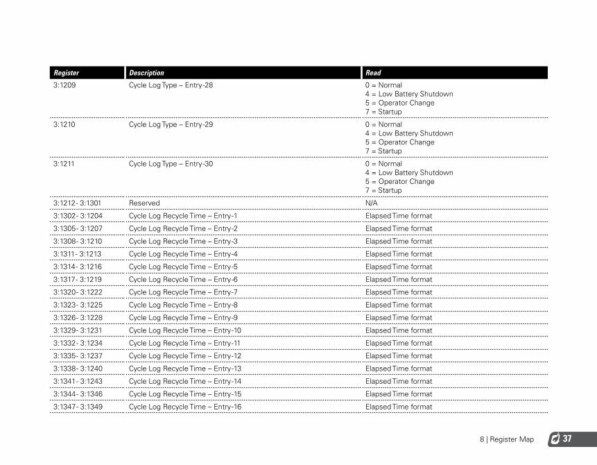
3:1209 Cycle Log Type – Entry -28 0 = Normal 4 = Low Battery Shutdown 5 = Operator Change 7 = Startup
3:1210 Cycle Log Type – Entry -29 0 = Normal 4 = Low Battery Shutdown 5 = Operator Change 7 = Startup
3:1211 Cycle Log Type – Entry -30 0 = Normal 4 = Low Battery Shutdown 5 = Operator Change 7 = Startup
3:1212 - 3:1301 Reserved N/A
3:1302 - 3:1204 Cycle Log Recycle Time – Entry -1 Elapsed Time format
3:1305 - 3:1207 Cycle Log Recycle Time – Entry -2 Elapsed Time format
3:1308 - 3:1210 Cycle Log Recycle Time – Entry -3 Elapsed Time format
3:1311 - 3:1213 Cycle Log Recycle Time – Entry -4 Elapsed Time format
3:1314 - 3:1216 Cycle Log Recycle Time – Entry -5 Elapsed Time format
3:1317 - 3:1219 Cycle Log Recycle Time – Entry -6 Elapsed Time format
3:1320 - 3:1222 Cycle Log Recycle Time – Entry -7 Elapsed Time format
3:1323 - 3:1225 Cycle Log Recycle Time – Entry -8 Elapsed Time format
3:1326 - 3:1228 Cycle Log Recycle Time – Entry -9 Elapsed Time format
3:1329 - 3:1231 Cycle Log Recycle Time – Entry -10 Elapsed Time format
3:1332 - 3:1234 Cycle Log Recycle Time – Entry -11 Elapsed Time format
3:1335 - 3:1237 Cycle Log Recycle Time – Entry -12 Elapsed Time format
3:1338 - 3:1240 Cycle Log Recycle Time – Entry -13 Elapsed Time format
3:1341 - 3:1243 Cycle Log Recycle Time – Entry -14 Elapsed Time format
3:1344 - 3:1346 Cycle Log Recycle Time – Entry -15 Elapsed Time format
3:1347 - 3:1349 Cycle Log Recycle Time – Entry -16 Elapsed Time format
8 | Register Map38
Register Description Read
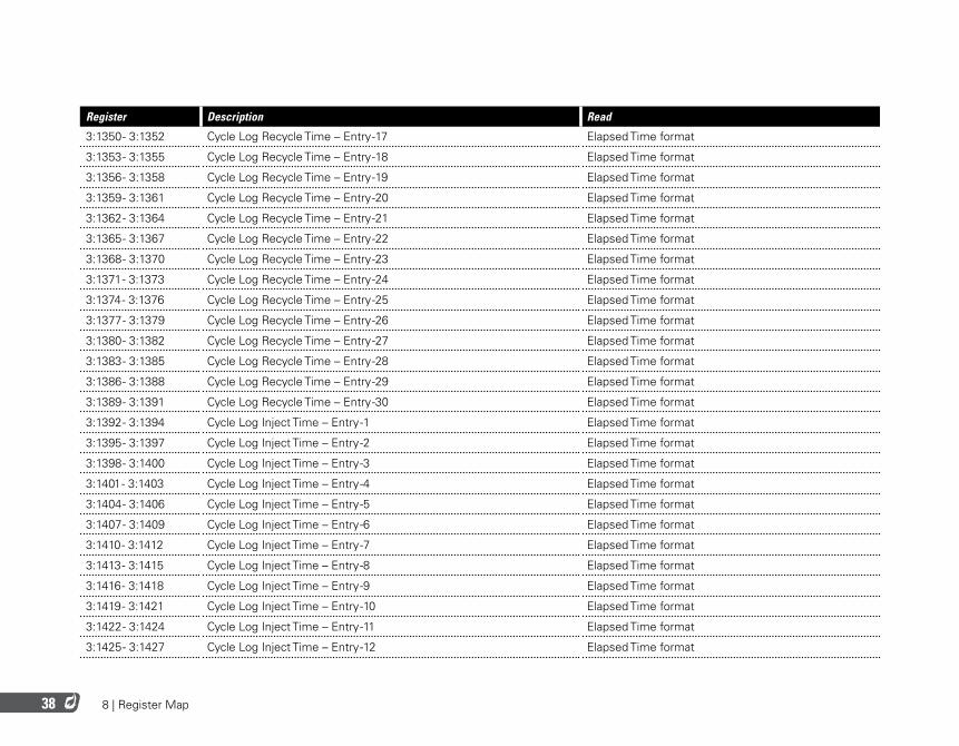
3:1350 - 3:1352 Cycle Log Recycle Time – Entry -17 Elapsed Time format
3:1353 - 3:1355 Cycle Log Recycle Time – Entry -18 Elapsed Time format
3:1356 - 3:1358 Cycle Log Recycle Time – Entry -19 Elapsed Time format
3:1359 - 3:1361 Cycle Log Recycle Time – Entry -20 Elapsed Time format
3:1362 - 3:1364 Cycle Log Recycle Time – Entry -21 Elapsed Time format
3:1365 - 3:1367 Cycle Log Recycle Time – Entry -22 Elapsed Time format
3:1368 - 3:1370 Cycle Log Recycle Time – Entry -23 Elapsed Time format
3:1371 - 3:1373 Cycle Log Recycle Time – Entry -24 Elapsed Time format
3:1374 - 3:1376 Cycle Log Recycle Time – Entry -25 Elapsed Time format
3:1377 - 3:1379 Cycle Log Recycle Time – Entry -26 Elapsed Time format
3:1380 - 3:1382 Cycle Log Recycle Time – Entry -27 Elapsed Time format
3:1383 - 3:1385 Cycle Log Recycle Time – Entry -28 Elapsed Time format
3:1386 - 3:1388 Cycle Log Recycle Time – Entry -29 Elapsed Time format
3:1389 - 3:1391 Cycle Log Recycle Time – Entry -30 Elapsed Time format
3:1392 - 3:1394 Cycle Log Inject Time – Entry -1 Elapsed Time format
3:1395 - 3:1397 Cycle Log Inject Time – Entry -2 Elapsed Time format
3:1398 - 3:1400 Cycle Log Inject Time – Entry -3 Elapsed Time format
3:1401 - 3:1403 Cycle Log Inject Time – Entry -4 Elapsed Time format
3:1404 - 3:1406 Cycle Log Inject Time – Entry -5 Elapsed Time format
3:1407 - 3:1409 Cycle Log Inject Time – Entry -6 Elapsed Time format
3:1410 - 3:1412 Cycle Log Inject Time – Entry -7 Elapsed Time format
3:1413 - 3:1415 Cycle Log Inject Time – Entry -8 Elapsed Time format
3:1416 - 3:1418 Cycle Log Inject Time – Entry -9 Elapsed Time format
3:1419 - 3:1421 Cycle Log Inject Time – Entry -10 Elapsed Time format
3:1422 - 3:1424 Cycle Log Inject Time – Entry -11 Elapsed Time format
3:1425 - 3:1427 Cycle Log Inject Time – Entry -12 Elapsed Time format
8 | Register Map 39
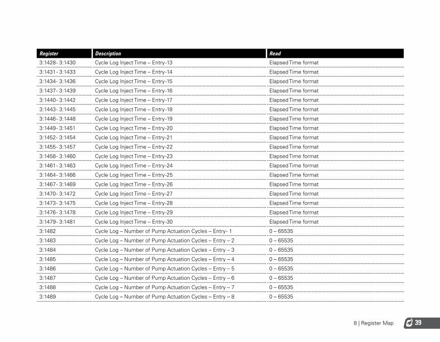
Register Description Read
3:1428 - 3:1430 Cycle Log Inject Time – Entry -13 Elapsed Time format
3:1431 - 3:1433 Cycle Log Inject Time – Entry -14 Elapsed Time format
3:1434 - 3:1436 Cycle Log Inject Time – Entry -15 Elapsed Time format
3:1437 - 3:1439 Cycle Log Inject Time – Entry -16 Elapsed Time format
3:1440 - 3:1442 Cycle Log Inject Time – Entry -17 Elapsed Time format
3:1443 - 3:1445 Cycle Log Inject Time – Entry -18 Elapsed Time format
3:1446 - 3:1448 Cycle Log Inject Time – Entry -19 Elapsed Time format
3:1449 - 3:1451 Cycle Log Inject Time – Entry -20 Elapsed Time format
3:1452 - 3:1454 Cycle Log Inject Time – Entry -21 Elapsed Time format
3:1455 - 3:1457 Cycle Log Inject Time – Entry -22 Elapsed Time format
3:1458 - 3:1460 Cycle Log Inject Time – Entry -23 Elapsed Time format
3:1461 - 3:1463 Cycle Log Inject Time – Entry -24 Elapsed Time format
3:1464 - 3:1466 Cycle Log Inject Time – Entry -25 Elapsed Time format
3:1467 - 3:1469 Cycle Log Inject Time – Entry -26 Elapsed Time format
3:1470 - 3:1472 Cycle Log Inject Time – Entry -27 Elapsed Time format
3:1473 - 3:1475 Cycle Log Inject Time – Entry -28 Elapsed Time format
3:1476 - 3:1478 Cycle Log Inject Time – Entry -29 Elapsed Time format
3:1479 - 3:1481 Cycle Log Inject Time – Entry -30 Elapsed Time format
3:1482 Cycle Log – Number of Pump Actuation Cycles – Entry - 1 0 – 65535
3:1483 Cycle Log – Number of Pump Actuation Cycles – Entry – 2 0 – 65535
3:1484 Cycle Log – Number of Pump Actuation Cycles – Entry – 3 0 – 65535
3:1485 Cycle Log – Number of Pump Actuation Cycles – Entry – 4 0 – 65535
3:1486 Cycle Log – Number of Pump Actuation Cycles – Entry – 5 0 – 65535
3:1487 Cycle Log – Number of Pump Actuation Cycles – Entry – 6 0 – 65535
3:1488 Cycle Log – Number of Pump Actuation Cycles – Entry – 7 0 – 65535
3:1489 Cycle Log – Number of Pump Actuation Cycles – Entry – 8 0 – 65535
8 | Register Map40
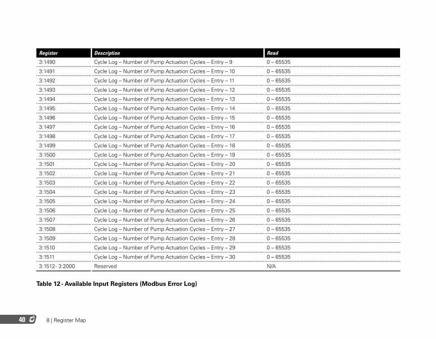
Register Description Read
3:1490 Cycle Log – Number of Pump Actuation Cycles – Entry – 9 0 – 65535
3:1491 Cycle Log – Number of Pump Actuation Cycles – Entry – 10 0 – 65535
3:1492 Cycle Log – Number of Pump Actuation Cycles – Entry – 11 0 – 65535
3:1493 Cycle Log – Number of Pump Actuation Cycles – Entry – 12 0 – 65535
3:1494 Cycle Log – Number of Pump Actuation Cycles – Entry – 13 0 – 65535
3:1495 Cycle Log – Number of Pump Actuation Cycles – Entry – 14 0 – 65535
3:1496 Cycle Log – Number of Pump Actuation Cycles – Entry – 15 0 – 65535
3:1497 Cycle Log – Number of Pump Actuation Cycles – Entry – 16 0 – 65535
3:1498 Cycle Log – Number of Pump Actuation Cycles – Entry – 17 0 – 65535
3:1499 Cycle Log – Number of Pump Actuation Cycles – Entry – 18 0 – 65535
3:1500 Cycle Log – Number of Pump Actuation Cycles – Entry – 19 0 – 65535
3:1501 Cycle Log – Number of Pump Actuation Cycles – Entry – 20 0 – 65535
3:1502 Cycle Log – Number of Pump Actuation Cycles – Entry – 21 0 – 65535
3:1503 Cycle Log – Number of Pump Actuation Cycles – Entry – 22 0 – 65535
3:1504 Cycle Log – Number of Pump Actuation Cycles – Entry – 23 0 – 65535
3:1505 Cycle Log – Number of Pump Actuation Cycles – Entry – 24 0 – 65535
3:1506 Cycle Log – Number of Pump Actuation Cycles – Entry – 25 0 – 65535
3:1507 Cycle Log – Number of Pump Actuation Cycles – Entry – 26 0 – 65535
3:1508 Cycle Log – Number of Pump Actuation Cycles – Entry – 27 0 – 65535
3:1509 Cycle Log – Number of Pump Actuation Cycles – Entry – 28 0 – 65535
3:1510 Cycle Log – Number of Pump Actuation Cycles – Entry – 29 0 – 65535
3:1511 Cycle Log – Number of Pump Actuation Cycles – Entry – 30 0 – 65535
3:1512 - 3:2000 Reserved N/A
Table 12 - Available Input Registers (Modbus Error Log)
8 | Register Map 41
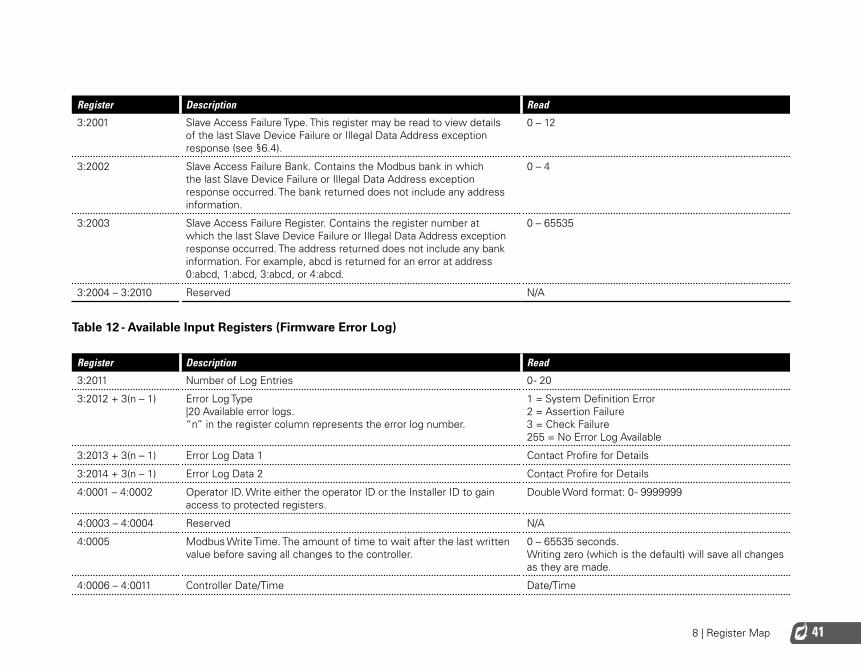
Register Description Read
3:2001 Slave Access Failure Type. This register may be read to view details of the last Slave Device Failure or Illegal Data Address exception response (see §6.4).
0 – 12
3:2002 Slave Access Failure Bank. Contains the Modbus bank in which the last Slave Device Failure or Illegal Data Address exception response occurred. The bank returned does not include any address information.
0 – 4
3:2003 Slave Access Failure Register. Contains the register number at which the last Slave Device Failure or Illegal Data Address exception response occurred. The address returned does not include any bank information. For example, abcd is returned for an error at address 0:abcd, 1:abcd, 3:abcd, or 4:abcd.
0 – 65535
3:2004 – 3:2010 Reserved N/A
Table 12 - Available Input Registers (Firmware Error Log)
Register Description Read
3:2011 Number of Log Entries 0 - 20
3:2012 + 3(n – 1) Error Log Type |20 Available error logs. “n” in the register column represents the error log number.
1 = System Definition Error 2 = Assertion Failure 3 = Check Failure 255 = No Error Log Available
3:2013 + 3(n – 1) Error Log Data 1 Contact Profire for Details
3:2014 + 3(n – 1) Error Log Data 2 Contact Profire for Details
4:0001 – 4:0002 Operator ID. Write either the operator ID or the Installer ID to gain access to protected registers.
Double Word format: 0 - 9999999
4:0003 – 4:0004 Reserved N/A
4:0005 Modbus Write Time. The amount of time to wait after the last written value before saving all changes to the controller.
0 – 65535 seconds. Writing zero (which is the default) will save all changes as they are made.
4:0006 – 4:0011 Controller Date/Time Date/Time
8 | Register Map42
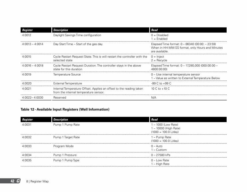
Register Description Read
4:0012 Daylight Savings Time configuration 0 = Disabled 1 = Enabled
4:0013 – 4:0014 Day Start Time – Start of the gas day. Elapsed Time format: 0 – 86340 (00:00: – 23:59) When in HH:MM:SS format, only Hours and Minutes are available.
4:0015 Cycle Restart Request State. This is will restart the controller with the selected state
0 = Inject 2 = Recycle
4:0016 – 4:0018 Cycle Restart Request Duration. The controller stays in the above state for this duration
Elapsed Time format: 0 – 17,280,000 (000:00:00 – 4800:00:00)
4:0019 Temperature Source 0 – Use internal temperature sensor 1 – Value as written to External Temperature Below
4:0020 External Temperature -99 C to +99 C
4:0021 Internal Temperature Offset. Applies an offset to the reading taken from the internal temperature sensor.
10 C to +10 C
4:0022– 4:0030 Reserved N/A
Table 12 - Available Input Registers (Well Information)
Register Description Read
4:0031 Pump 1 Pump Rate 1 – 1000 (Low Rate) 1 – 10000 (High Rate) (1000 = 100.0 L/day)
4:0032 Pump 1 Target Rate 1 – Pump Rate (1000 = 100.0 L/day)
4:0033 Program Mode 0 – Auto 1 – Custom
4:0034 Pump 1 Pressure 0 – 27580 kPa
4:0035 Pump 1 Pump Type 0 – Low Rate 1 – High Rate
8 | Register Map 43
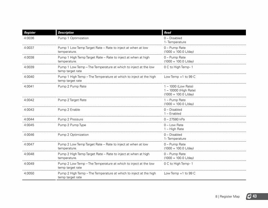
Register Description Read
4:0036 Pump 1 Optimization 0 – Disabled 1 - Temperature
4:0037 Pump 1 Low Temp Target Rate – Rate to inject at when at low temperature.
0 – Pump Rate (1000 = 100.0 L/day)
4:0038 Pump 1 High Temp Target Rate – Rate to inject at when at high temperature.
0 – Pump Rate (1000 = 100.0 L/day)
4:0039 Pump 1 Low Temp – The Temperature at which to inject at the low temp target rate
0 C to High Temp - 1
4:0040 Pump 1 High Temp – The Temperature at which to inject at the high temp target rate
Low Temp +1 to 99 C
4:0041 Pump 2 Pump Rate 1 – 1000 (Low Rate) 1 – 10000 (High Rate) (1000 = 100.0 L/day)
4:0042 Pump 2 Target Rate 1 – Pump Rate (1000 = 100.0 L/day)
4:0043 Pump 2 Enable 0 – Disabled 1 – Enabled
4:0044 Pump 2 Pressure 0 – 27580 kPa
4:0045 Pump 2 Pump Type 0 – Low Rate 1 – High Rate
4:0046 Pump 2 Optimization 0 – Disabled 1 - Temperature
4:0047 Pump 2 Low Temp Target Rate – Rate to inject at when at low temperature.
0 – Pump Rate (1000 = 100.0 L/day)
4:0048 Pump 2 High Temp Target Rate – Rate to inject at when at high temperature.
0 – Pump Rate (1000 = 100.0 L/day)
4:0049 Pump 2 Low Temp – The Temperature at which to inject at the low temp target rate
0 C to High Temp - 1
4:0050 Pump 2 High Temp – The Temperature at which to inject at the high temp target rate
Low Temp +1 to 99 C
8 | Register Map44
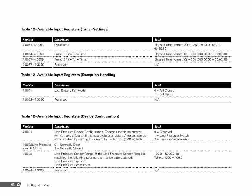
Table 12 - Available Input Registers (Timer Settings)
Register Description Read
4:0051 - 4:0053 Cycle Time Elapsed Time format: 30 s – 3599 s (000:00:30 – 00:59:59)
4:0054 - 4:0056 Pump 1 Fine Tune Time Elapsed Time format: 0s – 30s (000:00:00 – 00:00:30)
4:0057 - 4:0059 Pump 2 Fine Tune Time Elapsed Time format: 0s – 30s (000:00:00 – 00:00:30)
4:0057– 4:0070 Reserved N/A
Table 12 - Available Input Registers (Exception Handling)
Register Description Read
4:0071 Low Battery Fail Mode 0 – Fail Closed 1 – Fail Open
4:0072– 4:0080 Reserved N/A
Table 12 - Available Input Registers (Device Configuration)
Register Description Read
4:0081 Line Pressure Device Configuration. Changes to this parameter will not take effect until the next cycle or a restart. A restart can be accomplished by setting the Controller restart coil (0:0003) high.
0 = Disabled 1 = Line Pressure Switch 2 = Line Pressure Sensor
4:0082Line Pressure Switch Mode
0 = Normally Open 1 = Normally Closed
4:0083 Line Pressure Sensor Range. If the Line Pressure Sensor Range is modified the following parameters may be auto-updated: Line Pressure Trip Point Line Pressure Reset Point
100.0 – 5000.0 psi Where 1000 = 100.0
4:0084– 4:0100 Reserved N/A
8 | Register Map 45
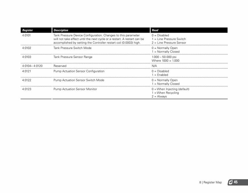
Register Description Read
4:0101 Tank Pressure Device Configuration. Changes to this parameter will not take effect until the next cycle or a restart. A restart can be accomplished by setting the Controller restart coil (0:0003) high.
0 = Disabled 1 = Line Pressure Switch 2 = Line Pressure Sensor
4:0102 Tank Pressure Switch Mode 0 = Normally Open 1 = Normally Closed
4:0103 Tank Pressure Sensor Range 1.000 – 50.000 psi Where 1000 = 1.000
4:0104– 4:0120 Reserved N/A
4:0121 Pump Actuation Sensor Configuration 0 = Disabled 1 = Enabled
4:0122 Pump Actuation Sensor Switch Mode 0 = Normally Open 1 = Normally Closed
4:0123 Pump Actuation Sensor Monitor 0 = When Injecting (default) 1 = When Recycling 2 = Always

9 | Acronyms
9 | Acronyms 47
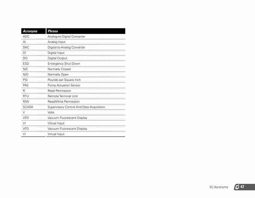
Acronyms PhraseADC Analog-to-Digital Converter
AI Analog Input
DAC Digital-to-Analog Converter
DI Digital Input
DO Digital Output
ESD Emergency Shut Down
N/C Normally Closed
N/O Normally Open
PSI Pounds per Square Inch
PAS Pump Actuation Sensor
R Read Permission
RTU Remote Terminal Unit
R/W Read/Write Permission
SCADA Supervisory Control And Data Acquisition
V Volts
VFD Vacuum Fluorescent Display
VI Virtual Input
VFD Vacuum Fluorescent Display
VI Virtual Input


www.profireenergy.com© 2014 PROFIRE