pc hardware servicing - · pdf filelearning outcome 1: plan and prepare for termination and...
TRANSCRIPT

1 | P a g e
PC HARDWARE SERVICING The Strengthened Technical‐Vocational Education Program
How to Use this Module .......................................................................................................
Introduction ..........................................................................................................................
Technical Terms ....................................................................................................................
Learning Outcome #1 .......................................................................................................... 1
Information Sheet #1‐1 ....................................................................................................... 2
Operation Sheet #1‐1 .......................................................................................................... 6
Learning Outcome #2 .......................................................................................................... 8
Information Sheet #2.1 ....................................................................................................... 9
Activity Sheet #2.1 ............................................................................................................ 10
Learning Outcome #3 ........................................................................................................ 13
Job Sheet

2 | P a g e
PC HARDWARE SERVICING The Strengthened Technical‐Vocational Education Program
Welcome to the Module “Terminating and Connecting Electrical Wiring and Electronic Circuits”. This module contains training materials and activities for you to complete. The unit of competency “Terminate and Connect Electrical Wiring and Electronic Circuits” contains knowledge, skills and attitudes required for a Computer Hardware Servicing NC II course. You are required to go through a series of learning activities in order to complete each of the learning outcomes of the module. In each learning outcome there are Job Sheets, and Activity Sheets. Follow these activities on your own and answer the Self-Check at the end of each learning activity. If you have questions, do not hesitate to ask your teacher for assistance. Recognition of Prior Learning (RPL) You may already have some of the knowledge and skills covered in this module because you have:
o been working for some time o completed training in this area. If you can demonstrate to your teacher that you are competent in a particular skill or
skills, talk to him/her about having them formally recognized so you do not have to do the same training again. If you have a qualification or Certificate of Competency from previous trainings show it to your teacher. If the skills you acquired are still current and relevant to this module, they may become part of the evidence you can present for RPL. If you are not sure about the currency of your skills, discuss it with your teacher.
After completing this module ask your teacher to assess your competency. Result of
your assessment will be recorded in your competency profile. All the learning activities are designed for you to complete at your own pace.
Inside this module you will find the activities for you to complete followed by
relevant information sheets for each learning outcome. Each learning outcome may have more than one learning activity.

3 | P a g e
PC HARDWARE SERVICING The Strengthened Technical‐Vocational Education Program
Program/Course : Computer Hardware Servicing NC II
Unit of Competency : Terminate and Connect Electrical Wiring and Electronic Circuits
Module : Terminating and Connecting Electrical Wiring and Electronic Circuits
INTRODUCTION
This module contains information and suggested learning activities on Computer Hardware
Servicing NC II. It includes the following competencies: plan and prepare for termination/
connections of electrical wiring/electronic circuits, terminate/connect electrical wiring/electronic
circuits, and test termination/connections of electrical wiring/electronic circuits.
It consists of three (3) learning outcomes. Each learning outcome contains learning activities
supported by each instructional sheet. Upon completion of this module, report to your teacher to
assess your achievement of knowledge and skills requirement of this module. If you pass the
assessment, you will be given a certificate of completion.
SUMMARY OF LEARNING OUTCOMES:
Upon completion of the module you should be able to:
LO1. Plan and prepare for termination and connection of electrical wiring and electronic circuits.
LO2. Terminate and connect electrical wiring and electronic circuits.
LO3. Test Termination and connection of electrical wiring and /electronic circuit.
REFERENCES:
1. Agpaoa, Feliciano, Interior and Exterior Wiring Troubleshooting, National books Store, 1991 2. Enriquez, Michael, Simple Electronics (Basic) Fully Illustrated, Antonio M. Andes Sr.
Electronics Book Series 3. www.electronics‐lab.com 4. www.wikipedia.com

4 | P a g e
PC HARDWARE SERVICING The Strengthened Technical‐Vocational Education Program
Voltage ‐ The measure of the push on each electron which makes the electron
move. The term potential difference and voltage are often used
interchangeably to mean the “push”, thus, you may see the term
electromotive force (EMF) or just the word potential to describe the
electron push in certain instances.
Current ‐ The flow of electrons in the circuit.
Resistance ‐ The opposition to current flow.
Power ‐ The rate of doing work.
Resistor ‐ A device designed intentionally to have a definite amount of
resistance
Capacitor ‐ A device that stores electrical energy.
Termination - The point where a line, channel or circuit ends.
OHS ‐ Occupational Health and Safety

5 | P a g e
PC HARDWARE SERVICING The Strengthened Technical‐Vocational Education Program
Program/ Course : Computer Hardware Servicing NC II
Unit of Competency : Terminate and Connect Electrical Wiring and Electronic Circuits
Module #3 : Terminating and Connecting Electrical Wiring and Electronic Circuits
Learning Outcome 1: Plan and Prepare for Termination and Connection of Electrical
Wiring and Electronic Circuits
Assessment Criteria:
1. Materials are checked according to specifications and task. 2. Appropriate tools and equipment are selected according to task requirements. 3. Task is planned to ensure that OHS guidelines and procedures are followed. 4. Electrical wiring electronics circuits are appropriately prepared for connection/
termination in accordance with instructions and worksite procedure.
References:
1. Agpaoa, Feliciano, Interior and Exterior Wiring Troubleshooting, National books Store, 1991
2. Enriquez, Michael, Simple Electronics (Basic) Fully Illustrated, Antonio M. Andes Sr. Electronics Book Series
3. Cardenas, Elpidio, Fundamentals and Elements of Electricity, National Book Store, 1991
4. www.wikipedia.com
6 | P a g e
PC HARDWARE SERVICING The Strengthened Technical‐Vocational Education Program
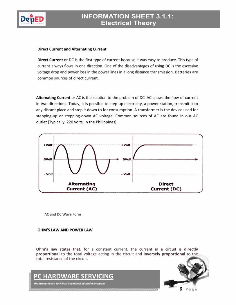
Direct Current and Alternating Current
Direct Current or DC is the first type of current because it was easy to produce. This type of
current always flows in one direction. One of the disadvantages of using DC is the excessive
voltage drop and power loss in the power lines in a long distance transmission. Batteries are
common sources of direct current.
Alternating Current or AC is the solution to the problem of DC. AC allows the flow of current
in two directions. Today, it is possible to step‐up electricity, a power station, transmit it to
any distant place and step it down to for consumption. A transformer is the device used for
stepping‐up or stepping‐down AC voltage. Common sources of AC are found in our AC
outlet (Typically, 220 volts, in the Philippines).
OHM’S LAW AND POWER LAW
Ohm’s law states that, for a constant current, the current in a circuit is directly proportional to the total voltage acting in the circuit and inversely proportional to the total resistance of the circuit.
AC and DC Wave Form

7 | P a g e
PC HARDWARE SERVICING The Strengthened Technical‐Vocational Education Program
The law may be expressed by the following equation if the current I is in amperes, EMF E is in volts, and the resistance R is in ohms.
The relationship of the foregoing three variables was discovered by Georg Simon Ohm,
who theorized that current is in direct proportion to resistance. The relationship is
explained algebraically, using this formula:
R = E/I
Resistance
E = I x R I = E/R
Voltage Current
where:
E – EMF in Volts R – Resistance I – Current in Amperes

8 | P a g e
PC HARDWARE SERVICING The Strengthened Technical‐Vocational Education Program
A. Practice Problems:
1.
2.
E = 25 V R = 25 Ω
Required…
G. I
H. P
I = ?
E = ? R = 72 Ω
Required…
E. E
F. P
I = 9A
E = ? P = 100W
Required…
C. R
D. E
I = 25 A
9 | P a g e
PC HARDWARE SERVICING The Strengthened Technical‐Vocational Education Program
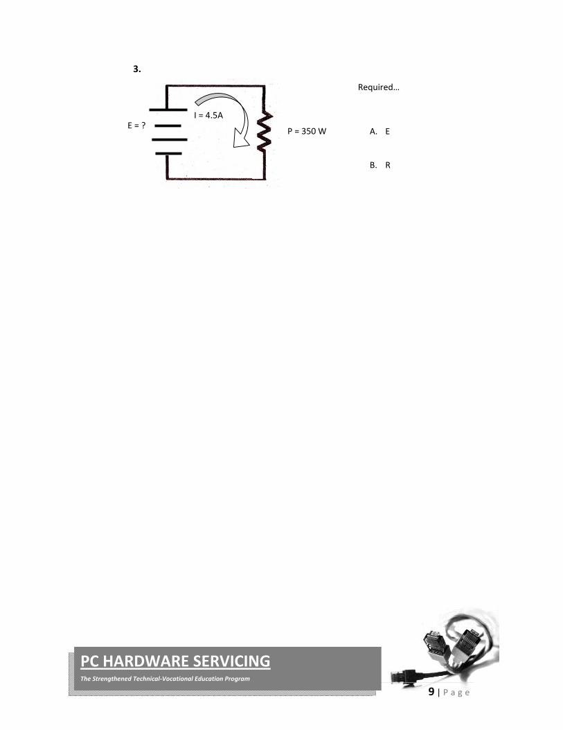
3.
E = ? P = 350 W
Required…
A. E
B. R
I = 4.5A

10 | P a g e
PC HARDWARE SERVICING The Strengthened Technical‐Vocational Education Program
A Simple circuit contains the minimum things needed to have a functioning electric
circuit. A simple circuit requires the following:
AC/DC source Equipment that will operate on either an AC or DC power source Battery – A dc voltage source containing two or more cells that convert
chemical energy to electrical energy. Cell‐ Single unit used to convert chemical energy into a DC electrical
voltage.
FUSE Once you design a simple circuit on electronics, it
is important to include a fuse in the primary or
secondary of a transformer.
Fuse is a safety device used to protect an electrical circuit from the effect of excessive current. Its essential component is usually a strip of metal that will melt at a given temperature. A fuse is so designed that the strip of metal can easily be placed in the electric circuit. If the current in the circuit exceed a predetermined value, the fusible metal will melt and thus break, or open the circuit.
A fuse is usually rated in Amperes, which represent the maximum continuous current it could handle without blowing.
The most popular type of fuse in Electronics is 3AG type. This code describes the case size and material where “G” indicates a glass materials and “A” indicates that intended for automotive application. A 3AG fuse measures approximately 32mm x 6mm.
Wires and Cable
A wire is a single slender rod or filament of drawn metal. This definition restricts the term to what would ordinarily be understood as solid wire. The word “slender” is used because the length of a wire is usually large when compared to its diameter. If a wire is covered with insulation, It is an insulated wire. Although the term “wire” properly refers to the metal, it also includes the insulation.
A conductor is a wire suitable for carrying an electric current.
11 | P a g e
PC HARDWARE SERVICING The Strengthened Technical‐Vocational Education Program
A stranded conductor is a conductor composed of a group of wire or any combination of group of wires. The wires in a stranded conductor are usually twisted together and not insulated from each other.
A cable is either a stranded conductor (single‐conductor cable) or a combination of conductors insulated from one another (multiple‐conductor cable). The term “cable” is a general one and usually applies only to the large sizes of conductor. A small cable is more often called a stranded wire or cord (such as that used for an iron or a lamp cord). Cables may be bare or insulated. Insulated cables may be sheathed (covered) with lead, or protective armor.
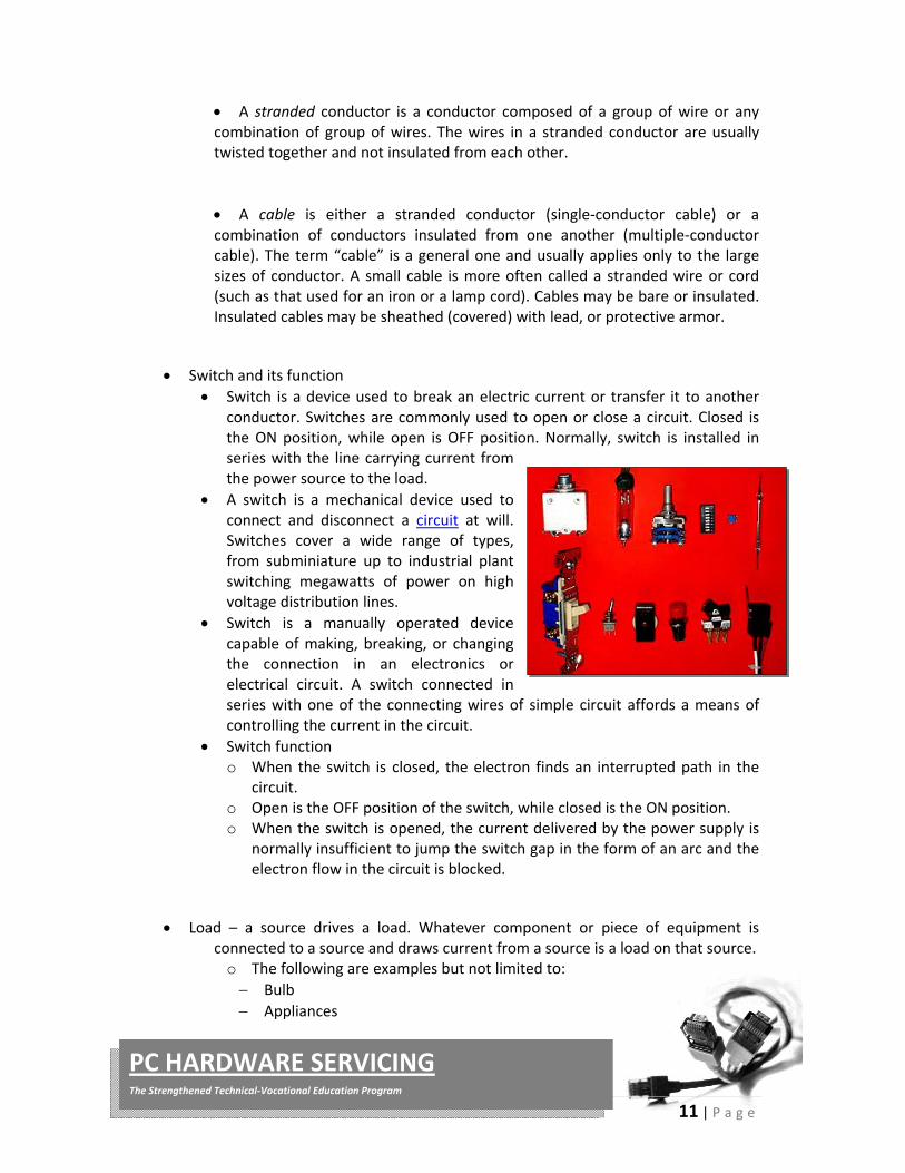
Switch and its function
Switch is a device used to break an electric current or transfer it to another conductor. Switches are commonly used to open or close a circuit. Closed is the ON position, while open is OFF position. Normally, switch is installed in series with the line carrying current from the power source to the load.
A switch is a mechanical device used to connect and disconnect a circuit at will. Switches cover a wide range of types, from subminiature up to industrial plant switching megawatts of power on high voltage distribution lines.
Switch is a manually operated device capable of making, breaking, or changing the connection in an electronics or electrical circuit. A switch connected in series with one of the connecting wires of simple circuit affords a means of controlling the current in the circuit.
Switch function o When the switch is closed, the electron finds an interrupted path in the
circuit. o Open is the OFF position of the switch, while closed is the ON position. o When the switch is opened, the current delivered by the power supply is
normally insufficient to jump the switch gap in the form of an arc and the electron flow in the circuit is blocked.
Load – a source drives a load. Whatever component or piece of equipment is connected to a source and draws current from a source is a load on that source.
o The following are examples but not limited to:
Bulb
Appliances

12 | P a g e
PC HARDWARE SERVICING The Strengthened Technical‐Vocational Education Program
I. Classifications of Electronic Component
A. Passive devices ‐ A Passive Device is one that contributes no power gain
(amplification) to a circuit or system. It has no control action and does not
require any input other than a signal to perform its function. In other words,
"A component with no brains!" Examples are Resistors, Capacitors and
Inductors.
RESISTOR
This is the most common component in electronics.
It is used mainly to control current and voltage
within the circuit. You can identify a simple resistor
by its simple cigar shape with a wire lead coming
out of each end. It uses a system of color coded
bands to identify the value of the component
(measured in Ohms)
Capacitors, or "caps", vary in size and shape ‐ from
a small surface mount model up to a huge electric
motor cap the size of paint can. Whatever the size
or shape, the purpose is the same. It stores
electrical energy in the form of electrostatic charge.
It is charged with a magnetic field and when that
field collapses it produces current in the opposite
direction. Inductors are used in Alternating Current
circuits to oppose changes in the existing current.

13 | P a g e
PC HARDWARE SERVICING The Strengthened Technical‐Vocational Education Program
B. Active Devices are components that are capable of controlling voltages or
currents and can create a switching action in the circuit. In other words,
"Devices with smarts!" Examples are Diodes, Transistors and Integrated
circuits.
Diodes are basically a one‐way valve for electrical
current. They let it flow in one direction (from
positive to negative) and not in the other direction.
Most diodes are similar in appearance to a resistor
and will have a painted line on one end showing the
direction or flow (white side is negative). If the
negative side is on the negative end of the circuit,
current will flow. If the negative is on the positive
side of the circuit no current will flow.
LEDs are simply diodes that emit light of one form
or another. They are used as indicator devices.
Example: LED lit equals machine on. They come in
several sizes and colors. Some even emit Infrared
Light which cannot be seen by the human eye.
The transistor is possibly the most important
invention of this decade. It performs two basic
functions. 1) It acts as a switch turning current on
and off. 2) It acts as an amplifier. This makes an
output signal that is a magnified version of the
input signal.
Integrated Circuits, or ICs, are complex circuits
inside one simple package. Silicon and metals are
used to simulate resistors, capacitors, transistors,
etc. It is a space saving miracle.

14 | P a g e
PC HARDWARE SERVICING The Strengthened Technical‐Vocational Education Program
ELECTRONIC SCHEMATIC SYMBOLS
Wires and connections
Component Circuit Symbol Function of Component
Wire To pass current very easily from one part of
a circuit to another.
Wires joined
A 'blob' should be drawn where wires are
connected (joined), but it is sometimes
omitted. Wires connected at 'crossroads'
should be staggered slightly to form two T‐
junctions, as shown on the right.
Wires not joined
In complex diagrams it is often necessary to
draw wires crossing even though they are
not connected. I prefer the 'bridge' symbol
shown on the right because the simple
crossing on the left may be misread as a
joint where you have forgotten to add a
'blob'!
Power Supplies/Source
Component Circuit Symbol Function of Component
Cell
Supplies electrical energy.
The larger terminal (on the left) is positive (+).
A single cell is often called a battery, but
strictly a battery is two or more cells joined
together.
Battery
Supplies electrical energy. A battery is more
than one cell.
The larger terminal (on the left) is positive (+).
DC supply
Supplies electrical energy.
DC = Direct Current, always flowing in one
direction.

15 | P a g e
PC HARDWARE SERVICING The Strengthened Technical‐Vocational Education Program
AC supply
Supplies electrical energy.
AC = Alternating Current, continually changing
direction.
Fuse
A safety device which will 'blow' (melt) if the
current flowing through it exceeds a specified
value.
Transformer
Two coils of wire linked by an iron core.
Transformers are used to step up (increase)
and step down (decrease) AC voltages. Energy
is transferred between the coils by the
magnetic field in the core. There is no electrical
connection between the coils.
Earth
(Ground)
A connection to earth. For many electronic
circuits this is the 0V (zero volts) of the power
supply, but for mains electricity and some
radio circuits it really means the earth. It is also
known as ground.
Output Devices/Loads: Lamps, Heater, Motor
Component Circuit Symbol Function of Component
Lamp (lighting)
A transducer which converts electrical
energy to light. This symbol is used for a
lamp providing illumination, for example a
car headlamp or torch bulb.
Lamp (indicator)
A transducer which converts electrical
energy to light. This symbol is used for a
lamp which is an indicator, for example a
warning light on a car dashboard.
Heater A transducer which converts electrical
energy to heat.
Motor A transducer which converts electrical
energy to kinetic energy (motion).
16 | P a g e
PC HARDWARE SERVICING The Strengthened Technical‐Vocational Education Program
Bell
A transducer which converts electrical
energy to sound.
Buzzer
A transducer which converts electrical
energy to sound.
Inductor
(Coil, Solenoid)
A coil of wire which creates a magnetic field
when current passes through it. It may have
an iron core inside the coil. It can be used
as a transducer converting electrical energy
to mechanical energy by pulling on
something.
Switches
Component Circuit Symbol Function of Component
Push Switch
(push‐to‐
make)
A push switch allows current to flow only when the
button is pressed. This is the switch used to operate a
doorbell.
Push‐to‐Break
Switch
This type of push switch is normally closed (on); it is
open (off) only when the button is pressed.
On‐Off Switch
(SPST)
SPST = Single Pole, Single Throw.
An on‐off switch allows current to flow only when it
is in the closed (on) position.
2‐way Switch
(SPDT)
SPDT = Single Pole, Double Throw.
A 2‐way changeover switch directs the flow of
current to one of two routes according to its position.
Some SPDT switches have a central off position and
are described as 'on‐off‐on'.

17 | P a g e
PC HARDWARE SERVICING The Strengthened Technical‐Vocational Education Program
Dual On‐Off
Switch
(DPST)
DPST = Double Pole, Single Throw.
A dual on‐off switch which is often used to switch
mains electricity because it can isolate both the live
and neutral connections.
Complete the table below:
A. Identify each of these symbols:
COMPONENTS SYMBOLS
1.
2.
3.
4.
5.

18 | P a g e
PC HARDWARE SERVICING The Strengthened Technical‐Vocational Education Program
B. Identify the following basic electronic components
COMPONENT FIGURE
1.
2.
3.
4.
19 | P a g e
PC HARDWARE SERVICING The Strengthened Technical‐Vocational Education Program
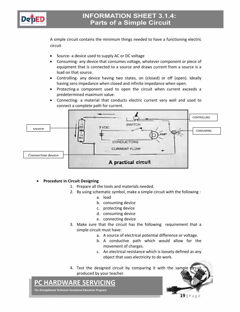
A simple circuit contains the minimum things needed to have a functioning electric
circuit
Source‐ a device used to supply AC or DC voltage
Consuming‐ any device that consumes voltage, whatever component or piece of equipment that is connected to a source and draws current from a source is a load on that source.
Controlling‐ any device having two states, on (closed) or off (open). Ideally having zero impedance when closed and infinite impedance when open.
Protecting‐a component used to open the circuit when current exceeds a predetermined maximum value.
Connecting‐ a material that conducts electric current very well and used to connect a complete path for current.
Procedure in Circuit Designing 1. Prepare all the tools and materials needed. 2. By using schematic symbol, make a simple circuit with the following :
a. load b. consuming device c. protecting device d. consuming device e. connecting device
3. Make sure that the circuit has the following requirement that a simple circuit must have:
a. A source of electrical potential difference or voltage. b. A conductive path which would allow for the
movement of charges. c. An electrical resistance which is loosely defined as any
object that uses electricity to do work.
4. Test the designed circuit by comparing it with the sample circuit produced by your teacher.
CONTROLLING
CONSUMINGsource
Connecting device

20 | P a g e
PC HARDWARE SERVICING The Strengthened Technical‐Vocational Education Program
A. Fill in the blanks with what is referred to by each of the following.
1. _______________________ Interconnection of components which provides an
electrical path between two or more components.
2. _______________________ A type of circuit in which the flow of current is cut off.
3. _______________________ A circuit in which the components are connected from
end to end so that the current has only one path to
follow through the circuit.
4. _______________________ A circuit where there is more than one path for the
current to flow through.
5. _______________________ A device used to supply AC or DC voltage.
6. _______________________ Any device having two states, ON or OFF.
7. _______________________ A safety device used to protect an electrical circuit
from the effect of excessive current.
8. _______________________ pathway for carrying an electrical current.
9. _______________________ Components or pieces of equipment connected to a
source which draws current from a source.
10. _______________________ A DC voltage source containing two or more cells that
convert chemical energy to electrical energy.

21 | P a g e
PC HARDWARE SERVICING The Strengthened Technical‐Vocational Education Program
A. Initial Steps in Using Analog Multi‐tester
1. Connect the test probe to the appropriate jack. The red test probe to the positive (+) jack and the black to the common (‐) jack.
2. Check if the pointer rests exactly at the infinite zero position in ohmmeter range.
‐COM
(Black)
+ POS
(Red)

22 | P a g e
PC HARDWARE SERVICING The Strengthened Technical‐Vocational Education Program
3. Check the probes if they are in condition. (Ohmmeter calibration) a. Set the Multi‐tester to corresponding selector resistance range. b. Short the two test probes lead together.
Zero Ohm
Adjustment
knob
Note:
The pointer should deflect
towards zero ohm reading

23 | P a g e
PC HARDWARE SERVICING The Strengthened Technical‐Vocational Education Program
B. Resistance Measurements 1. Always do the “Initial Steps in Using Analog Multi‐tester”. 2. In testing resistors, capacitors, diodes etc. do not touch both test probe lead,
because our body also has resistance that could affect the reading value of the electronic components we are testing.
3. If you do not know the value of the resistor to be measured, find the ohmmeter selector setting until you have a clear reading in the ohmmeter scale.
Zero ohm
Adjust the ohm adjustment if the pointer could not rest exactly at “O” ohm reading.
As indicated, the pointer rests out of the range of ohmmeter scale. Adjust the ohm adjustment counter clockwise until the pointer rests “O” ohm reading.
Ohmmeter Selector
Range
(x1, x10, x1K, x10K
ohms)
Ohm
Adjustment
Ohmmeter Scale
(From infinite to Zero)
Infinite Resistance
open resistor – Open
connection or

24 | P a g e
PC HARDWARE SERVICING The Strengthened Technical‐Vocational Education Program
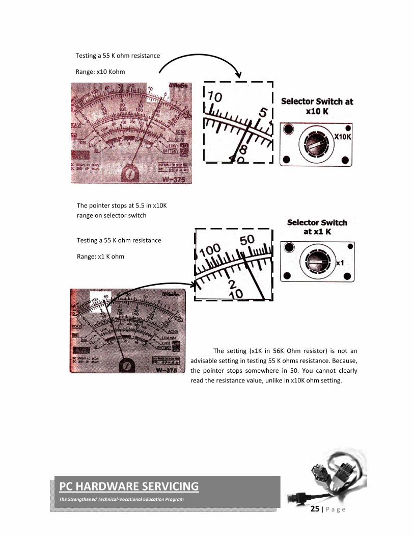
4. Select the desired resistance range scale with selector switch.
25 | P a g e
PC HARDWARE SERVICING The Strengthened Technical‐Vocational Education Program
Testing a 55 K ohm resistance
Range: x10 Kohm
The pointer stops at 5.5 in x10K
range on selector switch
Testing a 55 K ohm resistance
Range: x1 K ohm
The setting (x1K in 56K Ohm resistor) is not an
advisable setting in testing 55 K ohms resistance. Because,
the pointer stops somewhere in 50. You cannot clearly
read the resistance value, unlike in x10K ohm setting.