pbasic compiler manual · 2006-05-28 · picbasic compiler. however, the picbasic compiler will not...
TRANSCRIPT
PicBasic Compiler
microEngineering Labs, Inc.
COPYRIGHT NOTICE
Copyright ©2004 microEngineering Labs, Inc.
All rights reserved.
This manual describes the use and operation of the PicBasic Compiler
from microEngineering Labs, Inc. Use of the PicBasic Compiler without
first obtaining a license is a violation of law. To obtain a license, along
with the latest version of the product and documentation, contact
microEngineering Labs, Inc.
Publication and redistribution of this manual over the Internet or in any
other medium without prior written consent is expressly forbidden. In all
cases this copyright notice must remain intact and unchanged.
microEngineering Labs, Inc.
Box 60039
Colorado Springs CO 80960-0039
(719) 520-5323
(719) 520-1867 fax
email: [email protected]
web: www.melabs.com
TRADEMARKS
EPIC and PicBasic are trademarks of microEngineering Labs, Inc.
BASIC Stamp and PBASIC are trademarks of Parallax, Inc.
PICmicro is a registered trademark of Microchip Technology Inc.

PicBasic Compiler
microEngineering Labs, Inc.
6/04

PicBasic Compiler
i
TABLE OF CONTENTS
1. Introduction . . . . . . . . . . . . . . . . . . . . . . . . . . . . . . . . . . . . . . 1
1.1. About This Manual . . . . . . . . . . . . . . . . . . . . . . . . 2
2. Compiler Basics . . . . . . . . . . . . . . . . . . . . . . . . . . . . . . . . . . 3
2.1. The PICmicro MCUs . . . . . . . . . . . . . . . . . . . . . . . 3
2.2. The Pins . . . . . . . . . . . . . . . . . . . . . . . . . . . . . . . . 4
2.3. Software Installation . . . . . . . . . . . . . . . . . . . . . . . 5
2.4. Getting Started . . . . . . . . . . . . . . . . . . . . . . . . . . . 5
2.5. Program That PICmicro MCU . . . . . . . . . . . . . . . . 7
2.6. It’s Alive . . . . . . . . . . . . . . . . . . . . . . . . . . . . . . . . . 8
2.7. I’ve Got Troubles . . . . . . . . . . . . . . . . . . . . . . . . . . 9
2.8. Coding Style . . . . . . . . . . . . . . . . . . . . . . . . . . . . 11
2.8.1. Comments . . . . . . . . . . . . . . . . . . . . . . 11
2.8.2. Symbols . . . . . . . . . . . . . . . . . . . . . . . . 11
2.8.3. Labels . . . . . . . . . . . . . . . . . . . . . . . . . 12
2.8.4. GOTO . . . . . . . . . . . . . . . . . . . . . . . . . 12
3. Command Line Options . . . . . . . . . . . . . . . . . . . . . . . . . . . . 13
3.1. Usage . . . . . . . . . . . . . . . . . . . . . . . . . . . . . . . . . 13
3.2. Options . . . . . . . . . . . . . . . . . . . . . . . . . . . . . . . . 14
3.2.1. Option -C . . . . . . . . . . . . . . . . . . . . . . . 14
3.2.2. Option -D . . . . . . . . . . . . . . . . . . . . . . . 14
3.2.3. Option -L . . . . . . . . . . . . . . . . . . . . . . . 15
3.2.4. Option -OB . . . . . . . . . . . . . . . . . . . . . 15
3.2.5. Option -P## . . . . . . . . . . . . . . . . . . . . . 15
3.2.6. Option -Q . . . . . . . . . . . . . . . . . . . . . . . 16
3.2.7. Option -S . . . . . . . . . . . . . . . . . . . . . . . 16
4. PicBasic Programming . . . . . . . . . . . . . . . . . . . . . . . . . . . . 17
4.1. Comments . . . . . . . . . . . . . . . . . . . . . . . . . . . . . . 17
4.2. Numeric Constants . . . . . . . . . . . . . . . . . . . . . . . 17
4.3. String Constants . . . . . . . . . . . . . . . . . . . . . . . . . 17
4.4. Identifiers . . . . . . . . . . . . . . . . . . . . . . . . . . . . . . . 18
4.5. Line Labels . . . . . . . . . . . . . . . . . . . . . . . . . . . . . 18
4.6. Variables . . . . . . . . . . . . . . . . . . . . . . . . . . . . . . . 18
4.7. Symbols . . . . . . . . . . . . . . . . . . . . . . . . . . . . . . . . 21
4.8. Multi-statement Lines . . . . . . . . . . . . . . . . . . . . . 21
PicBasic Compiler
ii
5. PicBasic Statement Reference . . . . . . . . . . . . . . . . . . . . . 23
5.1. BRANCH . . . . . . . . . . . . . . . . . . . . . . . . . . . . . . 24
5.2. BUTTON . . . . . . . . . . . . . . . . . . . . . . . . . . . . . . 25
5.3. CALL . . . . . . . . . . . . . . . . . . . . . . . . . . . . . . . . . 26
5.4. DEBUG . . . . . . . . . . . . . . . . . . . . . . . . . . . . . . . 27
5.5. EEPROM . . . . . . . . . . . . . . . . . . . . . . . . . . . . . . 28
5.6. END . . . . . . . . . . . . . . . . . . . . . . . . . . . . . . . . . . 29
5.7. FOR..NEXT . . . . . . . . . . . . . . . . . . . . . . . . . . . . 30
5.8. GOSUB . . . . . . . . . . . . . . . . . . . . . . . . . . . . . . . 31
5.9. GOTO . . . . . . . . . . . . . . . . . . . . . . . . . . . . . . . . 32
5.10. HIGH . . . . . . . . . . . . . . . . . . . . . . . . . . . . . . . . 33
5.11. I2CIN . . . . . . . . . . . . . . . . . . . . . . . . . . . . . . . . 34
5.12. I2COUT . . . . . . . . . . . . . . . . . . . . . . . . . . . . . . 37
5.13. IF..THEN . . . . . . . . . . . . . . . . . . . . . . . . . . . . . 38
5.14. INPUT . . . . . . . . . . . . . . . . . . . . . . . . . . . . . . . 39
5.15. {LET} . . . . . . . . . . . . . . . . . . . . . . . . . . . . . . . . 40
5.15.1. Multiplication . . . . . . . . . . . . . . . . . . 41
5.15.2. Bitwise NOT Operators . . . . . . . . . . 41
5.16. LOOKDOW N . . . . . . . . . . . . . . . . . . . . . . . . . . 42
5.17. LOOKUP . . . . . . . . . . . . . . . . . . . . . . . . . . . . . 43
5.18. LOW . . . . . . . . . . . . . . . . . . . . . . . . . . . . . . . . . 44
5.19. NAP . . . . . . . . . . . . . . . . . . . . . . . . . . . . . . . . . 45
5.20. OUTPUT . . . . . . . . . . . . . . . . . . . . . . . . . . . . . 46
5.21. PAUSE . . . . . . . . . . . . . . . . . . . . . . . . . . . . . . . 47
5.22. PEEK . . . . . . . . . . . . . . . . . . . . . . . . . . . . . . . . 47
5.23. POKE . . . . . . . . . . . . . . . . . . . . . . . . . . . . . . . . 50
5.24. POT . . . . . . . . . . . . . . . . . . . . . . . . . . . . . . . . . 51
5.25. PULSIN . . . . . . . . . . . . . . . . . . . . . . . . . . . . . . 52
5.26. PULSOUT . . . . . . . . . . . . . . . . . . . . . . . . . . . . 53
5.27. PW M . . . . . . . . . . . . . . . . . . . . . . . . . . . . . . . . 54
5.28. RANDOM . . . . . . . . . . . . . . . . . . . . . . . . . . . . . 55
5.29. READ . . . . . . . . . . . . . . . . . . . . . . . . . . . . . . . . 56
5.30. RETURN . . . . . . . . . . . . . . . . . . . . . . . . . . . . . 57
5.31. REVERSE . . . . . . . . . . . . . . . . . . . . . . . . . . . . 58
5.32. SERIN . . . . . . . . . . . . . . . . . . . . . . . . . . . . . . . 58
5.33. SEROUT . . . . . . . . . . . . . . . . . . . . . . . . . . . . . 60
5.34. SLEEP . . . . . . . . . . . . . . . . . . . . . . . . . . . . . . . 63
5.35. SOUND . . . . . . . . . . . . . . . . . . . . . . . . . . . . . . 64
5.36. TOGGLE . . . . . . . . . . . . . . . . . . . . . . . . . . . . . 65
5.37. W RITE . . . . . . . . . . . . . . . . . . . . . . . . . . . . . . . 66

PicBasic Compiler
iii
6. Structure of a Compiled Program . . . . . . . . . . . . . . . . . . . . 67
6.1. Target (PICmicro MCU) Specific Header (B##.INC)
. . . . . . . . . . . . . . . . . . . . . . . . . . . . . . . . . . . . 67
6.2. PBH.INC . . . . . . . . . . . . . . . . . . . . . . . . . . . . . . . 68
6.3. PBC Generated Code . . . . . . . . . . . . . . . . . . . . . 69
6.4. PBL.INC . . . . . . . . . . . . . . . . . . . . . . . . . . . . . . . 69
7. Other PicBasic Considerations . . . . . . . . . . . . . . . . . . . . . . 71
7.1. How Fast is Fast Enough? . . . . . . . . . . . . . . . . . 71
7.2. Assembly Language . . . . . . . . . . . . . . . . . . . . . . 72
7.2.1. Programming in Assembly Language
. . . . . . . . . . . . . . . . . . . . . . . . . . . . . 72
7.2.2. Assembly Language Examples . . . . . . 73
7.2.3. Placement of In-line Assembly . . . . . . 76
7.2.4. The PICmicro Macro Assembler . . . . . 77
7.3. Interrupts . . . . . . . . . . . . . . . . . . . . . . . . . . . . . . . 78
7.4. Life After 2K . . . . . . . . . . . . . . . . . . . . . . . . . . . . . 80
8. Compiler / Stamp Differences . . . . . . . . . . . . . . . . . . . . . . . 81
8.1. Execution Speed . . . . . . . . . . . . . . . . . . . . . . . . . 81
8.2. Digital I/O . . . . . . . . . . . . . . . . . . . . . . . . . . . . . . . 81
8.3. Missing PC Interface . . . . . . . . . . . . . . . . . . . . . . 82
8.4. BUTTON . . . . . . . . . . . . . . . . . . . . . . . . . . . . . . . 82
8.5. EEPROM, READ and W RITE . . . . . . . . . . . . . . . 83
8.6. GOSUB/RETURN . . . . . . . . . . . . . . . . . . . . . . . . 83
8.7. RANDOM . . . . . . . . . . . . . . . . . . . . . . . . . . . . . . 84
8.8. SERIN/SEROUT . . . . . . . . . . . . . . . . . . . . . . . . . 84
8.9. Low Power Instructions . . . . . . . . . . . . . . . . . . . . 84
8.10. SLEEP . . . . . . . . . . . . . . . . . . . . . . . . . . . . . . . . 84
Appendix A . . . . . . . . . . . . . . . . . . . . . . . . . . . . . . . . . . . . . . . . 87
Summary of Microchip Assembly Instruction Set . . . . 87
Appendix B . . . . . . . . . . . . . . . . . . . . . . . . . . . . . . . . . . . . . . . . 89
Contact Information . . . . . . . . . . . . . . . . . . . . . . . . . . . 89
PicBasic Compiler
iv

PicBasic Compiler
1
1. Introduction
The PicBasic Compiler (or PBC) makes it quick and easy for you to
program Microchip Technology’s powerful PICmicro microcontrollers
(MCUs). The English-like BASIC language is much easier to read and
write than the quirky Microchip assembly language.
PBC also allows programs written for the original BASIC Stamp I to be
compiled for direct execution on members of the PICmicro MCU family of
microcontrollers. W hy would you want to do this?
Speed
Since PBC programs execute directly from the code space of the
PICmicro MCU rather than being fetched from a serial EEPROM, PBC
programs execute much faster than equivalent programs on a BASIC
Stamp. In fact, some instructions execute hundreds of times faster!
Cost
W hy pay $34 per project or, worse yet, per product? PBC allows
programs to be compiled directly into PICmicro MCUs costing $2 to $10.
W ith this kind of savings, the investment in the PicBasic Compiler and a
PICmicro MCU programmer could easily pay for itself after only a few
projects. Better yet, this lower cost could turn what was just a good idea
into a viable and competitive product.
Program Size
There is no fixed limit on the number of statements a program can have.
Maximum program length is dependent upon how many different
instructions are used (i.e. the number of different library routines that
must be loaded) and the code space available in the particular PICmicro
MCU.
PICmicro MCU Hardware
PBC defaults to create files that run on a PIC16F84 (or PIC16F84A)
clocked at 4MHz. Only a minimum of other parts are necessary: 2 22pf
capacitors for the 4MHz crystal, a 4.7K pull-up resistor tied to the /MCLR
pin and a suitable 5- volt power supply.
PicBasic Compiler
2
Many PICmicro MCUs other than the 16F84 may be used with the
PicBasic Compiler. However, the PicBasic Compiler will not work with
the older 16C5x series PICmicro MCUs. The 16C5x only provides a two
level stack. The PicBasic Compiler requires the 8 level stack provided by
the 14-bit core PICmicro MCUs.
1.1. About This Manual
This manual cannot be a full treatise on the BASIC language. It
describes the PicBasic Compiler instruction set and provides examples
on how to use it. If you are not familiar with BASIC programming, you
should acquire a book on the topic. Or just jump right in. BASIC is
designed as an easy-to-use language and there are additional example
programs on the disk and web site that can help get you started.
The next section of this manual covers installing the PicBasic Compiler
and writing your first program. Following is a section that describes
different options for compiling programs.
Programming basics are covered next, followed by a reference section
listing each PicBasic command in detail. The reference section shows
each command prototype, a description of the command and some
examples. Curly brackets, {}, indicate optional parameters.
The remainder of the manual provides information for advanced
programmers - all the inner workings of the compiler.

PicBasic Compiler
3
2. Compiler Basics
2.1. The PICmicro MCUs
The PicBasic Compiler produces code that may be programmed into a
wide variety of PICmicro microcontrollers having from 8 to 40 or more
pins and various on-chip features including A/D converters and hardware
timers and serial ports.
There are some PICmicro MCUs that will not work with the PicBasic
Compiler, notably the PIC16C5x series including the PIC16C54 and
PIC16C58. These PICmicro MCUs are based on the older 12-bit core
rather than the more current 14-bit core. The PicBasic Compiler requires
some of the features only available with the 14-bit core, the foremost of
which being the 8-level stack.
There are many, many PICmicro MCUs, some pin compatible with the ‘5x
series, that may be used with the PicBasic Compiler. See the
README.TXT file for the latest chip support list. For direct replacement of
a PIC16C54, 56 or 58, the PIC16C554, 558, 620(A), 621(A) and 622(A)
work well with the compiler and are very nearly the same price.*
For general purpose PICmicro MCU development using the PicBasic
Compiler, the PIC16F84 and PIC16F628 are the current PICmicro MCUs
of choice. These 18-pin microcontrollers uses flash technology to allow
rapid erasing and reprogramming to speed program debugging. W ith the
click of the mouse in the programming software, the PICmicro MCU can
be instantly erased and then reprogrammed again and again. Other
PICmicro MCUs in the 12C67x, 14000 and 16Cxxx series are either one-
time programmable (OTP) or have a quartz window in the top (JW ) to
allow erasure by exposure to ultraviolet light for several minutes.
The PIC16F84 also contains 64 bytes (128 bytes for the PIC16F628) of
non-volatile data EEPROM memory that can be used to store program
data and other parameters even when the power is turned off. This data
area can be accessed simply by using the PicBasic Compiler’s READ and
WRITE commands. (Program code is always permanently stored in the
PICmicro MCU’s code space whether the power is on or off.)
By using the ‘F84 for initial program testing, the debugging process may
be sped along. Once the main routines of a program are operating
PicBasic Compiler
4
satisfactorily, a PICmicro MCU with more capabilities or expanded
features of the compiler may be utilized.
W hile many PICmicro MCU features will be discussed in this manual, for
full PICmicro MCU information it is necessary to obtain the appropriate
PICmicro MCU Data Sheets or the CD-ROM from Microchip Technology.
Refer to Appendix B for contact information.
*Selling price is dictated by Microchip Technology Inc. and its distributors.
2.2. The Pins
Pins used by PicBasic Compiler commands are numbered 0 - 7 as with
the BASIC Stamp I. These pins are mapped onto PICmicro MCU
hardware port B such that Pin0 refers to PORTB pin 0 or simply
PORTB.0 (or RB0), Pin1 refers to PORTB.1 and so forth up to Pin7
referring PORTB.7. The pin number, 0 - 7, has nothing to do with the
physical pin number of a PICmicro MCU. Depending on the particular
PICmicro MCU, Pin0 could be physical pin 6, 21 or 33, but in every case
it is PORTB.0.
PicBasic instructions that reference a pin number such as HIGH or LOW
want only the pin number 0 - 7, eg. High 3 (set Pin3 high). If High
Pin3 is entered instead, the results are unexpected. Always use only
the number or a SYMBOL that equates to a number with pin manipulation
instructions.
On the other hand, if the current state of a pin is required, to read a
switch for example, the whole pin name would be used, eg. If Pin4 =
0 Then loop. In this case the state of Pin4 (PORTB.4) is read and if it
is low (0) the program jumps to the label loop:. If Pin4 is high (1), the
program continues with the next instruction after the If..Then.
All of the pins may be set at the same time using the predefined variable
Pins. For example, Pins = 255 sets all of the pins high. The variable
Dirs is also predefined to allow setting of the pin’s directions.
There are only 8 pins, Pin0 - Pin7, defined by the BS1 while a PICmicro
MCU may have 13, 22, 33 or more actual I/O pins. Some library routines
such as I2COUT make use of some of these additional I/O pins

PicBasic Compiler
5
automatically. For access to other I/O pins, the PEEK and POKE
instructions were created.
2.3. Software Installation
The included software should be copied to your hard drive before use.
To install the software to your hard drive, run (click on) INSTALL.BAT. If
the PBC directory already exists, you may get an error message and the
installation will continue.
All of the necessary files will be installed to a subdirectory named C:\PBC
on the hard drive. The README.TXT file has the latest information about
the PicBasic Compiler.
2.4. Getting Started
For operation of the PicBasic Compiler you will use the included IDE or a
text editor or word processor for creation of your program source file,
some sort of PICmicro MCU programmer such as our EPIC Plus
PICmicro Programmer or melabs Serial Programmer, and the PicBasic
Compiler itself. Of course you also need a PC to run it all on.
The sequence of events goes something like this:
First, start the included or one of the other available IDEs/editors. Select
the PICmicro MCU you intend to use from the IDE’s drop-down list. Next,
create the BASIC source file for the program or open one of the BASIC
source files included with PBC. The source file name usually (but isn’t
required to) ends with the extension .BAS.
The text file that is created must be pure ASCII text. It must not contain
any special codes that might be inserted by word processors for their
own purposes. You are usually given the option of saving the file as pure
DOS or ASCII text by most word processors.
The following program provides a good first test of a PICmicro MCU in
the real world. You may type it in or you can simply grab it from the
SAMPLES subdirectory included on the original PicBasic Compiler
distribution disk. The file is named BLINK.BAS. The BASIC source file
should be created in or moved to the same directory where the PBC.EXE
file is located.
PicBasic Compiler
6
‘Example program to blink an LED connected to PORTB.0
about once a second
loop: High 0 ‘Turn on LED
Pause 500 ‘Delay for .5 seconds
Low 0 ‘Turn off LED
Pause 500 ‘Delay for .5 seconds
Goto loop ‘Go back and blink LED forever
End
Once you are satisfied that the program you have written will work
flawlessly, you can execute the PicBasic Compiler by clicking on the
IDE’s build or compile button. If you are using DOS, enter PBP followed
by the name of your text file at a DOS prompt. For example, if the text
file you created is named BLINK.BAS, at the DOS command prompt
enter:
PBC blink
The compiler will display an initialization (copyright) message and
process your file. If it likes your file, it will create an assembler source
code file (in this case named BLINK.ASM) and automatically invoke its
assembler to complete the task. If all goes well, the final PICmicro MCU
code file will be created (in this case, BLINK.HEX). If you have made the
compiler unhappy, it will issue a string of errors that will need to be
corrected in your BASIC source file before you try compilation again.
To help ensure that your original file is flawless, it is best to start by
writing and testing a short piece of your program, rather than to write the
entire 100,000 line monolith all at once and then try to debug it from end
to end.
The PicBasic Compiler defaults to creating code for the PIC16F84. To
compile code for PICmicro MCUs other than the ‘F84, simply use the -P
command line option described later in the manual to specify a different
target processor. For example, if you intend to run the above program,
BLINK.BAS, on a PIC16C74, compile it using the command:
PBC -p16C74 blink
PicBasic Compiler
7
2.5. Program That PICmicro MCU
There are two steps left - putting your compiled program into the
PICmicro microcontroller and testing it.
The PicBasic Compiler generates standard 8-bit Merged Intel HEX
(.HEX) files that may be used with any PICmicro MCU programmer
including our EPIC Plus PICmicro Programmer and melabs Serial
Programmer. PICmicro MCUs cannot be programmed with BASIC
Stamp programming cables.
The following is an example of how a PICmicro MCU may be
programmed using one of our programmers.
Make sure there are no PICmicro MCUs installed in the programmer
programming socket or any attached adapters.
If you are using the EPIC Programmer, hook it to the PC parallel printer
port using a DB25 male to DB25 female printer extension cable.
If you are using the melabs Serial Programmer, hook it to the PC serial
port using a DB9 male to DB9 female serial cable or hook it to the USB
port using a USB-to-serial adapter.
Plug the AC adapter into the wall and then into the programmer (or attach
2 fresh 9-volt batteries to the EPIC Programmer and connect the “Batt
ON” jumper. Using an AC adapter instead of batteries is highly
recommended.)
The LED(s) on the EPIC Programmer may be on or off at this point. Do
not insert a PICmicro MCU into the programming socket when an LED is
on or before the programming software has been started. The LED
should glow green on the melabs Serial Programmer indicating it is
ready.
Launch the programmer software. Once the programming screen is
displayed, select the PICmicro MCU you will be programming. Next, use
the mouse to click on Open file. Select BLINK.HEX or another file you
would like to program into the PICmicro MCU from the dialog box.
Once the file has been loaded, you can look at the Code or Memory
window to see your PICmicro MCU program code. You should also look
PicBasic Compiler
8
at the Configuration window and verify that it is as desired before
proceeding.
In general, the Oscillator should be set to XT for a 4MHz crystal and the
W atchdog Timer should be set to ON for PicBasic programs. Most
importantly, Code Protect should be OFF when programming any
windowed (JW ) PICmicro MCUs. You may not be able to erase a
windowed PICmicro MCU that has been code protected. You can find
more information on these configuration fuses in the Microchip data sheet
for the device you are using.
W hen it all looks marvelous, it is time to insert a PICmicro MCU into the
programming socket and click on Program. The PICmicro MCU will first
be checked to make sure it is blank and then your code will be
programmed into it.
Once the programming is complete and the LED is no longer red, it is
time to test your program.
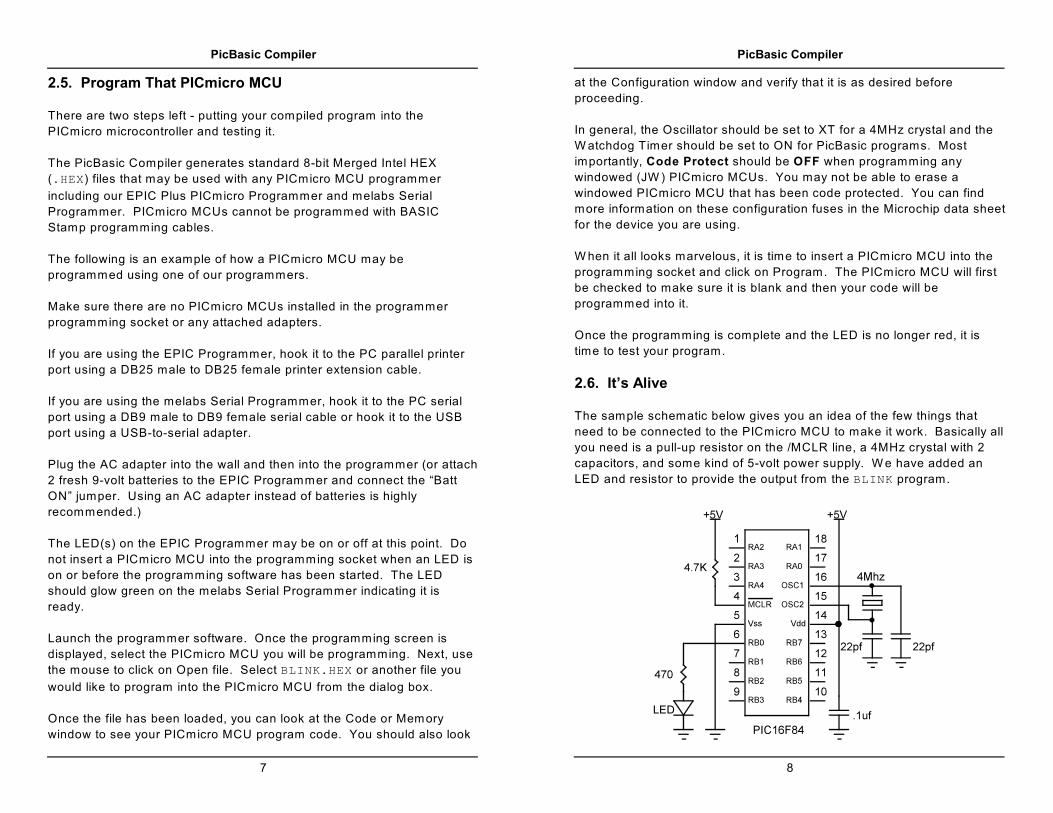
2.6. It’s Alive
The sample schematic below gives you an idea of the few things that
need to be connected to the PICmicro MCU to make it work. Basically all
you need is a pull-up resistor on the /MCLR line, a 4MHz crystal with 2
capacitors, and some kind of 5-volt power supply. W e have added an
LED and resistor to provide the output from the BLINK program.
PicBasic Compiler
9
Build and double check this simple circuit on a breadboard and plug in
the PICmicro MCU you just programmed. Our line of PICProto
prototyping boards is perfect for this kind of thing.
Connect a power supply. Your PICmicro MCU should come to life and
start blinking the LED about once a second. If it does not blink, check all
of the connections and make sure 5 volts is present at the appropriate
pins on the PICmicro MCU.
From these simple beginnings, you can create your own world-
conquering application.
2.7. I’ve Got Troubles
The most common problems with getting PICmicro MCUs running involve
making sure the few external components are of the appropriate value
and properly connected to the PICmicro MCU. Following are some hints
to help get things up and running.
Make sure the /MCLR pin is connected to 5 volts either through some
kind of voltage protected reset circuit or simply with a 4.7K resistor. If
you leave the pin unconnected, its level floats around and sometimes the
PICmicro MCU will work but usually it won’t. The PICmicro MCU has an
on-chip power-on-reset circuit so in general just an external pull-up
resistor is adequate. But in some cases the PICmicro MCU may not
power up properly and an external circuit may be necessary. See the
Microchip PICmicro MCU data books for more information.
Be sure you have a good crystal with the proper value capacitors
connected to it. Capacitor values can be hard to read. If the values are
off too much, the oscillator won’t start and run properly. A 4MHz crystal
with two 22pf (picofarad) ceramic disk capacitors is a good start for most
PICmicro MCUs. Once again, check out the Microchip data books for
additional thoughts on the matter.
Make sure your power supply is up to the task. W hile the PICmicro MCU
itself consumes very little power, the power supply must be filtered fairly
well. If the PICmicro MCU is controlling devices that pull a lot of current
from your power supply, they can put enough of a glitch on the supply
lines to cause the PICmicro MCU to stop working properly. Even an LED
display can create enough of an instantaneous drain to momentarily
PicBasic Compiler
10
clobber a small power supply (like a 9-volt battery) and cause the
PICmicro MCU to lose its place.
Check the PICmicro MCU data sheets. Some devices have features that
can interfere with expected pin operations. The PIC16C62x and ‘F62x
parts (the 16C620, 621, 622, 16F627 and 628) are a good example of
this. These PICmicro MCUs have analog comparators on PORTA.
W hen these chips start up, PORTA is set to analog mode. This makes
the pin functions on PORTA work in an unexpected manner. To change
the pins to digital, simply add the lines:
Symbol CMCON = $1f
Poke CMCON, 7
near the front of your program.
Any PICmicro MCU with analog inputs, such as the PIC12C67x,
PIC16C7xx and PIC16F87x series devices, will come up in analog mode.
You must set the pins to digital if that is how you intend to use them:
Symbol ADCON1 = $9f
Poke ADCON1, 7
Another example of potential disaster is that PORTA, pin 4 exhibits
unusual behavior when used as an output. This is because the pin has
an open collector output rather then the usual bipolar stage of the rest of
the output pins. This means it can pull to ground when set to 0, but it will
simply float when set to a 1, instead of going high. To make this pin act
in the expected manner, add a pull-up resistor between the pin and 5
volts. The value of the resistor may be between 1K and 33K, depending
on the drive necessary for the connected input. This pin acts as any
other pin when used as an input.
All of the PICmicro MCU pins are set to inputs on power-up. If you need
a pin to be an output, set it to an output, or use a PicBasic command that
does it for you. Once again, review the PICmicro MCU data sheets to
become familiar with the idiosyncrasies of a particular part.
Start small. W rite short programs to test features you are unsure of or
might be having trouble with. Once these smaller programs are working
properly, you can build on them.

PicBasic Compiler
11
Try doing things a different way. Sometimes what you are trying to do
looks like it should work but doesn’t, no matter how hard you pound on it.
Usually there is more than one way to skin a program. Try approaching
the problem from a different angle and maybe enlightenment will ensue.
2.8. Coding Style
W riting readable and maintainable programs is an art. There are a few
simple techniques you can follow that may help you become an artist.
2.8.1. Comments
Use lots of comments. Even though it may be perfectly obvious to you
what the code is doing as you write it, someone else looking at the
program (or even yourself when you are someone else later in life) may
not have any idea of what you were trying to achieve. W hile comments
take up space in your BASIC source file, they do not take up any
additional space in the PICmicro MCU so use them freely.
Make the comments tell you something useful about what the program is
doing. A comment like “Set Pin0 to 1" simply explains the syntax of the
language but does nothing to tell you why you have the need to do this.
Something more like “Turn on the Battery Low LED” might be a lot more
useful.
A block of comments before a section of code and at the beginning of the
program can describe what is about to happen in more detail than just the
space remaining after each statement. But don’t include a comment
block instead of individual line comments - use both.
At the beginning of the program describe what the program is intended to
do, who wrote it and when. It may also be useful to list revision
information and dates. Even specifying what each pin is connected to
can be helpful in remembering what hardware this particular program is
designed to run on. If it is intended to be run with a non-standard crystal
or special compiler options, be sure to list those.
2.8.2. Symbols
Use SYMBOL to make the name of a pin or variable something more
coherent than Pin0 or B1. In addition to the liberal use of comments,
PicBasic Compiler
12
descriptive pin and variable names can greatly enhance readability. The
following code fragment demonstrates:
Symbol BattLED = Pin0 ‘Assign Pin0 a more
useful name
Symbol Capacity = B1 ‘Variable B1 will
contain the remaining
battery capacity
If Capacity < 10 Then battlow ‘If battery
capacity is
low, go
indicate it
Goto othercode ‘Else go do something
else
battlow: BattLED = 1 ‘Turn on the Battery Low
LED
Goto othercode ‘Go about other business
2.8.3. Labels
Labels should also be more meaningful than “label1:" or “here:”. Even a
label like “loop:” is more descriptive (though only slightly). Usually the
line or routine you are jumping to does something unique. Try and give
at least a hint of its function with the label, and then follow up with a
comment.
2.8.4. GOTO
Finally, try not to use too many GOTOs. W hile the language is not as
robust as it might be and GOTOs are a necessary evil, try to minimize their
use as much as possible. Try to write your code in logical sections and
not jump around too much. GOSUBs can be helpful in achieving this.

PicBasic Compiler
13
3. Command Line Options
3.1. Usage
The PicBasic Compiler can be invoked from the DOS command line
using the following command format :
PBC Options Filename
Zero or more options can be used to modify the manner in which PBC
compiles the specified file. Options begin with a minus ( '- ' ). The
character following the minus is a letter which selects the option.
Additional characters may follow if the Option requires more
information. Each Option must be separated by a space though no
spaces may occur within an Option. Any Option not recognized by
PBC will generate a fatal error.
The first item not starting with a minus is assumed to be the filename. If
no extension is specified and the -Q option is not invoked, the default
extension .BAS is used. If a path is specified, that directory is searched
for the named file. Regardless of where the source file is found, files
generated by PBC are placed in the current directory.
By default, PBC automatically launches the assembler (PM.EXE) if the
compilation is performed without error. PBC expects to find PM.EXE in
the same directory as PBC.EXE. If the compilation has errors or the -S
option is used, PM is not launched.
If PBC is invoked with no parameters or filename, a brief help screen is
displayed.
PicBasic Compiler
14
3.2. Options
Option Description
C Suppress PBC Extensions
D†Generates Listing, Symbol Table, and Map File
L†Generates Listing
OB†Generates Binary rather than Merged Intel HEX
P## Specify Target (e.g. PIC16F84)
Q Forces use of explicit extension for Source Name
S Skips execution of Assembler when done
† Option is passed directly to PM, if invoked after compilation.
3.2.1. Option -C
In order to given the user options in extending the PBASIC language,
PBC provides some additional capabilities above and beyond the original
specifications for PBASIC. Commands such as PEEK and POKE, inline
assembly, the CALL statement, and additional variables (W7 through W39
and B14 through B79) are language extensions. The -C option disables
these extensions, forcing strict compatibility with original PBASIC on the
program being compiled. Using any of these extensions with -C will
generate errors.
This option is useful mainly for programs developed on the BASIC Stamp
I which may have variable names which conflict with extension keywords.
3.2.2. Option -D
The -D option causes the assembler to generate a symbol table, a listing
and a map file in addition to the normal executable image. See the
PICmicro Macro Assembler's manual on disk for more information on the
-D option.

PicBasic Compiler
15
3.2.3. Option -L
The -L option causes the assembler to generate a listing in addition to
the normal executable image. See the PICmicro Macro Assembler's
manual on disk for more information on the -L option.
Unlike PM, PBC's -L option doesn't allow the user to select an arbitrary
name for the listing file.
3.2.4. Option -OB
The -OB option forces the assembler to generate the program's
executable image as binary rather than the normal Merged Intel HEX.
See the PICmicro Macro Assembler's manual on disk for more
information on the -OB option.
3.2.5. Option -P##
By default, PBC compiles programs for the PIC16F84. PBC
accomplishes this by adding the following line to the beginning of
generated programs:
include "B16F84.INC"
The -P option can be used to select another target from the PICmicro
MCU family. For example:
PBC -p16F628 filename
would generate this line at the start of the program:
include "B16F628.INC"
This would allow the generated program to assemble and run on a
PIC16F628. Check the INC directory for available B*.INC files.
PicBasic Compiler
16
3.2.6. Option -Q
Normally, when no extension is explicitly specified for the source
filename, the default extension .BAS is used. The -Q option prevents this
and forces the programmer to explicitly define the extension (if any) of the
source filename.
3.2.7. Option -S
Normally, when PBC successfully compiles a program, it automatically
launches the assembler. This is done to convert the assembler output of
PBC to an executable image. The -S option prevents this, leaving PCB's
output in the generated .ASM file.
Since -S prevents the assembler from being invoked, options that are
simply passed to the assembler (-D, -L, and -OB) are effectively
overridden by -S.

PicBasic Compiler
17
4. PicBasic Programming
4.1. Comments
All well written programs contain adequate comments, unless you're
Microsoft, in which case they're contained on three CD-ROMs. A PBC
comment starts with either the REM keyword or the single quote (‘ ). All
following characters on this line are ignored.
4.2. Numeric Constants
PBC allows numeric constants to be defined in the three bases: decimal,
binary and hexadecimal. Binary values are defined using the prefix '% '
and hexadecimal values using the prefix '$ '. Decimal values are the
default and require no prefix.
100 ‘ Decimal Value 100
%100 ‘ Binary Value for Decimal 4
$100 ‘ Hexadecimal Value for Decimal 256
For ease of programming, single characters are converted to their ASCII
equivalents. Character constants must be quoted using double quotes
and must contain only one character (otherwise, they are string
constants).
"A" ‘ ASCII Value for Decimal 65
"d" ‘ ASCII Value for Decimal 100
4.3. String Constants
PBC doesn't provide string handling capabilities, but strings can be used
with some commands. A string contains one or more characters and is
delimited by double quotes. No escape sequences are supported for non-
ASCII characters (although most PBC commands have this handling
built-in).
"Hello" ‘ String (Short for "H","e","l","l","o")
Strings are usually treated as a list of individual character values.
PicBasic Compiler
18
4.4. Identifiers
An identifier is, quite simply, a name. Identifiers are used in PBC for line
labels and symbol names. An identifier is any sequence of letters, digits,
and underscores, although it must not start with a digit. Identifiers are not
case sensitive, thus label, LABEL and Label are all treated as equivalent.
And while labels might be any number of characters in length, PBC only
recognizes the first 32.
4.5. Line Labels
In order to mark statements that the program might wish to reference with
the GOTO or GOSUB commands, PBC uses line labels. Unlike many older
BASICs, PBC doesn't allow line numbers and doesn't require that each
line be labeled. Rather, any PBC line may start with a line label, which is
simply an identifier followed by a colon ( : ).
here: serout 0,N2400,("Hello, World!",13,10)
goto here
4.6. Variables
A number of variables have been predefined for temporary data storage
in your PicBasic program. Byte-sized variables are named B0, B1, B2
and so forth. W ord-sized variables are named W0, W1, W2 and so forth.
These word-sized variables are made up of two byte-sized variables. For
example, W0 consists of B0 and B1; W1 is made up of B2 and B3 and so
forth. Any of these variables can, in effect, be renamed using the
SYMBOL command to have more meaning within your program.
These variables are actually stored in the PICmicro MCU’s RAM
registers. B0 is stored in the first available RAM location, $0C for the
PIC16F84 and some of the smaller PICmicro MCUs, or $20 for the
PIC16C74 and other larger PICmicro MCUs. Refer to the Microchip
PICmicro MCU data books for the actual location of the start of the RAM
registers for a given PICmicro MCU.
The variables are assigned to RAM sequentially up to and including B21
at which point variables internal to the compiler library subroutines are
assigned. These assignments are done in the file PBH.INC in the INC
subdirectory. You may refer to it for additional information.

PicBasic Compiler
19
For a PICmicro MCU with only 36 bytes of RAM, such as the PIC16C84,
the 22 user variable bytes and the internal library variables use all of the
RAM that is available. For larger PICmicro MCUs like the PIC16F84 with
68 bytes of RAM and the PIC16C74 with 192 bytes of RAM, additional
user variables may be accessed. These variables continue at B22 and
run through B79 (also W11 through W39.) A particular PICmicro MCU
may not have actual RAM at all of these additional locations. If you try to
use a variable with no RAM location, the compiler will not generate an
error, but your program will not do what you expect.
This table lists the highest user variable names that should be used with
each PICmicro MCU:
BASIC Stamp I B13 W6
PIC16C61
B21 W10
PIC16C71
PIC16C710
PIC16C84
PIC16F83
PIC12F629
B47 W23PIC12F675
PIC16F630
PIC16F676
PIC16C711B51 W25
PIC16F84
PIC16C554
B63 W31PIC16C620
PIC16C621
All other
supported
PICmicro MCUs
B79 W39
PicBasic Compiler
20
The first two bytes, B0 and B1, may also be used as bit variables: Bit0,
Bit1, ..., Bit15.
Additionally, the variable names Port, Dirs and Pins are predefined.
Pins references PICmicro MCU hardware PORTB. Dirs references the
data direction register for PICmicro MCU hardware PORTB (TRISB). A
Dir of 0 sets its associated Pin to an input and a Dir of 1 sets its
associated Pin to an output. Most instructions set the Pin ’s direction
automatically. Port is a word variable that combines Pins and Dirs.
Like W0, these are overlaid and can be referenced as bits (Pin0, Pin1...
and Dir0, Dir1...).
W hen powered up or reset, Dirs is set to $00 (all pins input) and all
other variables are set to $00. All variable values are unsigned. Thus, bits
have the value 0 or 1, bytes 0 to 255, and words 0 to 65535.
The following table lists the predefined variables:
W ord Variables Byte Variables Bit Variables
W0B0 Bit0,Bit1,... Bit7
B1 Bit8,Bit9,... Bit15
W1B2
B3
W2B4
B5
......
...
W39B78
B79
PortPins Pin0,Pin1,... Pin7
Dirs Dir0,Dir1,... Dir7
W hile the use of fixed names might seem to be limiting and lead to ugly
programs, these variables may be given more useful names via the
SYMBOL statement.

PicBasic Compiler
21
4.7. Symbols
In order to make programs more readable, PBC allows the user to define
his own symbols. These symbols may be used to represent constants,
variables or other symbols. They may not be used for line labels. Only
one symbol may be defined per SYMBOL statement.
Symbol Ten = 10 ‘ Symbolic Constants
Symbol Count = W3 ‘ Named Word Variable
Symbol BitVar = BIT0 ‘ Named Bit Variable
Symbol Alias = BitVar ‘ An Alias for BitVar
4.8. Multi-statement Lines
In order to allow more compact programs and logical grouping of related
commands, PBC supports the use of the colon (:) to separate
statements placed on the same line. Thus, the following two examples
are equivalent:
W2 = W0
W0 = W1
W1 = W2
is the same as:
W2 = W0 : W0 = W1 : W1 = W2
This does not, however, change the size of the generated code.
PicBasic Compiler
22

PicBasic Compiler
23
5. PicBasic Statement Reference
BRANCH Computed GOTO (equiv. to ON..GOTO).
BUTTON Debounce and auto-repeat input on specified pin.
CALL Call assembly language subroutine at specified label.†
DEBUG Debugging statement (Ignored by PBC).
EEPROM Define initial contents of on-chip EEPROM.
END Stop execution and enter low power mode.
FOR..NEXT Repeatedly execute statement(s).
GOSUB Call BASIC subroutine at specified label.
GOTO Continue execution at specified label.
HIGH Make pin output high.
I2CIN Read bytes from I C device.2 †
I2COUT Write bytes to I C device.2 †
IF..THEN GOTO if specified condition is true.
INPUT Make pin an input.
[LET] Perform math and assign result to variable.
LOOKDOWN Search table for value.
LOOKUP Fetch value from table.
LOW Make pin output low.
NAP Power down processor for short period of time.
OUTPUT Make pin output.
PAUSE Delay (1mSec resolution).
PEEK Read byte from PICmicro MCU register.†
POKE Write byte to PICmicro MCU register.†
POT Read potentiometer on specified pin.
PULSIN Measure pulse width (10uSec resolution).
PULSOUT Generate pulse (10uSec resolution).
PWM Output pulse width modulated pulse train to pin.
RANDOM Generate pseudo-random number.
READ Read byte from on-chip EEPROM.
RETURN Continue execution at statement following GOSUB.
REVERSE Make output pin an input or an input pin an output.
SERIN Asynchronous serial input (8N1).
SEROUT Asynchronous serial output (8N1).
SLEEP Power down processor.
SOUND Generate tone or white-noise on specified pin.
TOGGLE Make pin output and toggle state.
WRITE Write byte to on-chip EEPROM.
† PicBasic language extension not found in PBASIC.
PicBasic Compiler
24
5.1. BRANCH
BRANCH Offset, ( Label{, Label} )
Uses Offset to index into the list of labels. Execution resumes at the
indexed label. For example, if Offset is zero, execution resumes at the
first label specified in the list. If Offset is one, at the second label. And
so on. If Offset is equal to or greater than the number of labels, no
action is taken and execution resumes with the following statement.
Branch B10,(label1,label2,label3) ‘If B10=0
goto label1;
if B10=1
goto label2;
if B10=2
goto label3

PicBasic Compiler
25
5.2. BUTTON
BUTTON Pin, Down, Delay, Rate, Var, Action, Label
Read input, perform debounce and auto-repeat on Pin.
Pin Pin number (0..7).
Down State of pin when button is pressed (0..1).
Delay Cycle count before auto-repeat starts (0..255). If 0, no debounce
or auto-repeat is performed. If 255, debounce, but no auto-
repeat, is performed.
Rate Auto-repeat rate (0..255).
Var Byte variable used for delay/repeat countdown. Should be
initialized to 0 prior to use.
ActionState of button to perform GOTO (0 if not pressed, 1 if pressed).
Label Execution resumes at this label if Action is true.
Button 2,0,100,10,B0,0,skip ‘Check for button
pressed on Pin2
and goto skip if
not
PicBasic Compiler
26
5.3. CALL
CALL Label
Executes the assembly language subroutine named Label. CALL is a
PicBasic Compiler statement and is not supported on the BASIC Stamp.
See the section on assembly language for more information.
Call pass ‘Call assembly language subroutine
named pass

PicBasic Compiler
27
5.4. DEBUG
PBC does not support the PBASIC DEBUG statement. PBC will, however,
parse DEBUG statements correctly and report syntax errors.
PicBasic Compiler
28
5.5. EEPROM
EEPROM { Location, } ( Constant{, Constant} )
Stores constants in consecutive bytes in on-chip EEPROM. If the optional
location value is omitted, the first EEPROM statement starts storing at
address 0 and subsequent statements store at the following locations. If
the location value is specified, it specifies the location where these
values are stored.
Constant can be a numeric constant or a string constant. Only the least
significant byte of numeric values are stored. Strings are stored as
consecutive bytes of ASCII values. No length or terminator is added
automatically.
EEPROM only works with PICmicro MCUs with on-chip EEPROM such as
the PIC16F84 and PIC16F628. The data is stored in the EEPROM space
at the time the PICmicro MCU is programmed, not each time the program
is run.
Eeprom 5,(10,20,30) ‘Store 10, 20 and 30
starting at EEPROM
location 5
PicBasic Compiler
29
5.6. END
END
Stops program execution and enters the low power mode by executing
continuous NAP commands.
End
PicBasic Compiler
30
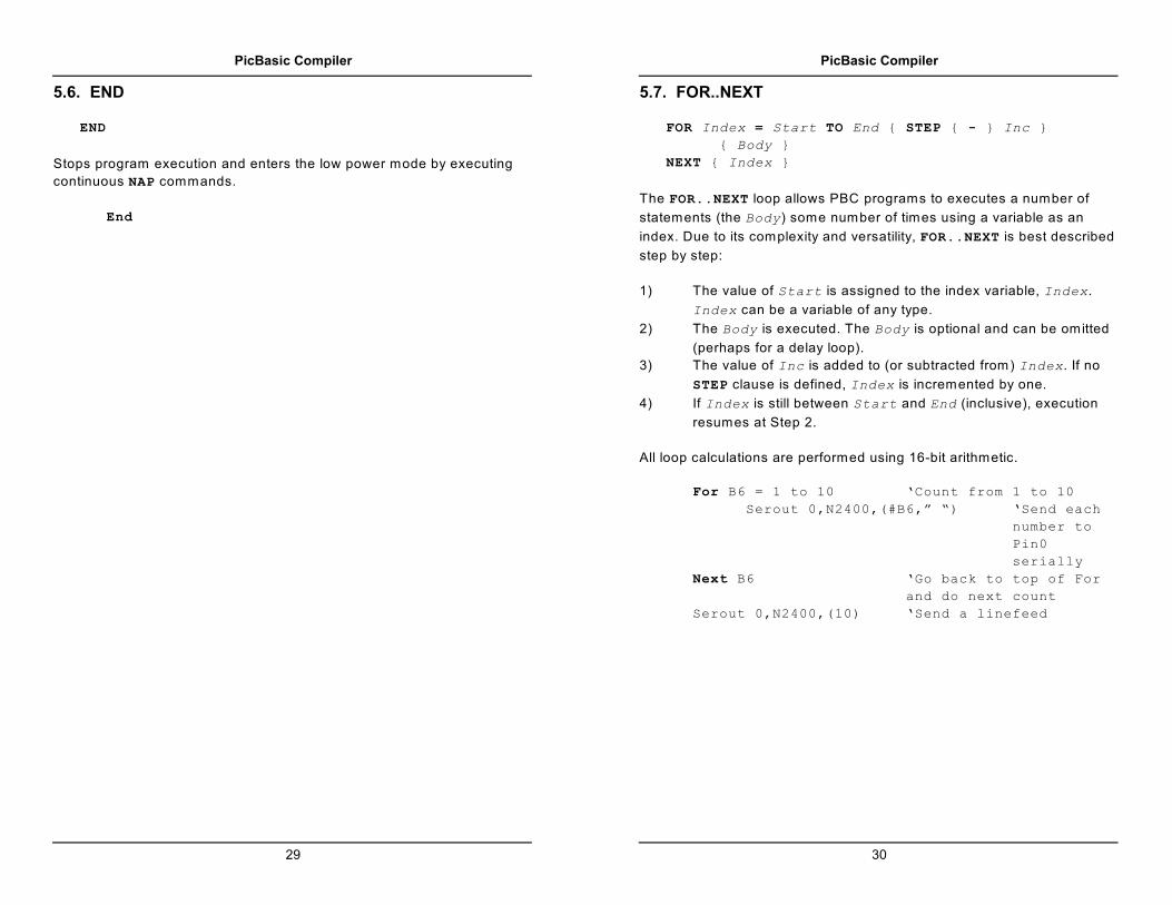
5.7. FOR..NEXT
FOR Index = Start TO End { STEP { - } Inc }
{ Body }
NEXT { Index }
The FOR..NEXT loop allows PBC programs to executes a number of
statements (the Body) some number of times using a variable as an
index. Due to its complexity and versatility, FOR..NEXT is best described
step by step:
1) The value of Start is assigned to the index variable, Index.
Index can be a variable of any type.
2) The Body is executed. The Body is optional and can be omitted
(perhaps for a delay loop).
3) The value of Inc is added to (or subtracted from) Index. If no
STEP clause is defined, Index is incremented by one.
4) If Index is still between Start and End (inclusive), execution
resumes at Step 2.
All loop calculations are performed using 16-bit arithmetic.
For B6 = 1 to 10 ‘Count from 1 to 10
Serout 0,N2400,(#B6,” “) ‘Send each
number to
Pin0
serially
Next B6 ‘Go back to top of For
and do next count
Serout 0,N2400,(10) ‘Send a linefeed

PicBasic Compiler
31
5.8. GOSUB
GOSUB Label
Executes the statements at Label. Unlike GOTO, when the RETURN
statement is reached, execution resumes with the statement following the
GOSUB statement. The code between Label and the RETURN statement
is called a subroutine.
Subroutines can be nested. In other words, it is possible for a subroutine
to call other subroutines. Such nesting should be restricted to no more
than four levels deep.
Gosub beep ‘Execute subroutine named beep
...
beep: High 0 ‘Turn on LED connected to Pin0
Sound 1,(80,10) ‘Beep speaker connected to
Pin1
Low 0 ‘Turn off LED connected to Pin0
Return ‘Go back to main routine that called
us
PicBasic Compiler
32
5.9. GOTO
GOTO Label
Program execution continues with the statements at Label.
Goto send ‘Jump to statement labeled send
...
send: Serout 0,N2400,(“Hi”) ‘Send “Hi” out Pin0
serially
PicBasic Compiler
33
5.10. HIGH
HIGH Pin
Makes the specified pin output high. The pin is automatically made an
output pin. Only the pin number itself, i.e. 0 to 7, is specified (i.e. NOTPin0.)
High 0 ‘Make Pin0 an output and set it high
(~5 volts)
PicBasic Compiler
34
5.11. I2CIN
I2CIN Control, Address, Var{, Var}
Sends Control and Address out the I C clock and data lines and puts2
the byte(s) received into Var.
I2CIN and I2COUT can be used to read and write data to a serial
EEPROM with a 2-wire I C interface such as the Microchip 24LC01B,2
24LC02B and similar devices. This allows data to be stored in non-
volatile memory so that it can be maintained even after the power is
turned off. These commands operate in the I C master byte read and2
write modes and may also be used to talk to other devices with an I C2
interface like temperature sensors and A/D converters.
The lower 7 bits of the Control byte contain the control code along with
chip select or additional address information, depending on the particular
device. The high order bit is a flag indicating whether the following
Address is to be sent as an 8 bit or 16 bit address. If this flag is low, the
Address is sent as 8 bits. The control code for a serial EEPROM is
usually %1010.
For example, when communicating with a 24LC01B, the Address
required is 8 bits, the control code is %1010 and the chip select is unused
so the Control byte would be %01010000 or $50. Formats of Control
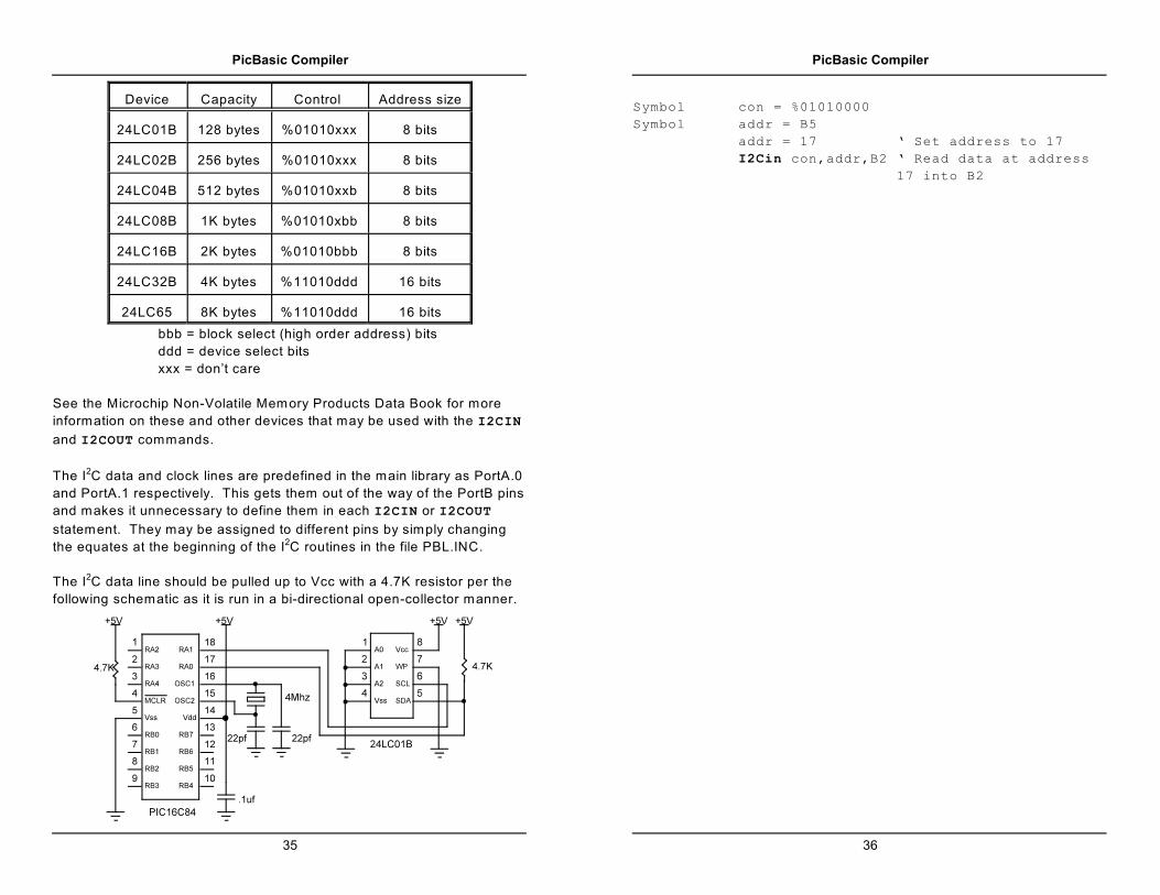
bytes for some of the different parts follow:
PicBasic Compiler
35
Device Capacity Control Address size
24LC01B 128 bytes %01010xxx 8 bits
24LC02B 256 bytes %01010xxx 8 bits
24LC04B 512 bytes %01010xxb 8 bits
24LC08B 1K bytes %01010xbb 8 bits
24LC16B 2K bytes %01010bbb 8 bits
24LC32B 4K bytes %11010ddd 16 bits
24LC65 8K bytes %11010ddd 16 bits
bbb = block select (high order address) bits
ddd = device select bits
xxx = don’t care
See the Microchip Non-Volatile Memory Products Data Book for more
information on these and other devices that may be used with the I2CIN
and I2COUT commands.
The I C data and clock lines are predefined in the main library as PortA.02
and PortA.1 respectively. This gets them out of the way of the PortB pins
and makes it unnecessary to define them in each I2CIN or I2COUT
statement. They may be assigned to different pins by simply changing
the equates at the beginning of the I C routines in the file PBL.INC.2
The I C data line should be pulled up to Vcc with a 4.7K resistor per the2
following schematic as it is run in a bi-directional open-collector manner.
PicBasic Compiler
36
Symbol con = %01010000
Symbol addr = B5
addr = 17 ‘ Set address to 17
I2Cin con,addr,B2 ‘ Read data at address
17 into B2

PicBasic Compiler
37
5.12. I2COUT
I2COUT Control, Address, ( Value{, Value })
I2COUT sends Control and Address out the I C clock and data lines2
followed by Value.
W hen writing to a serial EEPROM it is necessary to wait 10ms (device
dependent) for the write to complete before attempting communication
with the device again. If a subsequent I2CIN or I2COUT is attempted
before the write is complete, the access will be ignored.
W hile a single I2COUT statement may be used to write multiple bytes at
once, doing so would violate the above write timing requirement for serial
EEPROMs. The multiple byte write feature may be useful with I C2
devices other than serial EEPROMs that don’t have to wait between
writes.
See the I2CIN command above for the rest of the story.
Symbol con = %01010000
Symbol addr = B5
addr = 17 ‘ Set address to 17
I2Cout con,addr,(56) ‘ Send the byte 56
to address 17
Pause 10 ‘ Wait 10ms for write to
complete
addr = 127 ‘ Set address to 127
I2Cout con,addr,(B12) ‘ Send the byte in
B12 to address 127
Pause 10 ‘ Wait 10ms for write to
complete
PicBasic Compiler
38
5.13. IF..THEN
IF Comp { AND/OR Comp } THEN Label
Performs one or more comparisons. Each Comp term can relate a
variable to a constant or other variable and must be in the following form:
Var ( < | <= | = | <> | >= | > ) Value
All comparisons are unsigned since PBC only supports unsigned types. A
variable must occur on the left.
The THEN in an IF..THEN is essentially a GOTO. If the condition is true,
the program will GOTO the label after the THEN. If the condition evaluates
to false, the program will continue at the next line after the IF..THEN.
Another statement may not be placed after the THEN, it must be a label.
If Pin0 = 0 Then pushd ‘If button connected to
Pin0 is pushed (0), jump
to label pushd
If B0 >= 40 Then old ‘If the value in
variable B0 is greater
than or equal to 40,
jump to old
PicBasic Compiler
39
5.14. INPUT
INPUT Pin
Makes the specified pin an input. Only the pin number itself, i.e. 0 to 7, is
specified (i.e. NOT Pin0.)
Input 1 ‘Make Pin1 an input
PicBasic Compiler
40
5.15. {LET}
{ LET } Var = { - } Value { Op Value }
Assigns a value to a variable. The value may be a constant, the value of
another variable or the result of one or more binary operations. The
operations are performed strictly left to right and all operations are
performed with 16-bit precision. Unary negation may only be performed
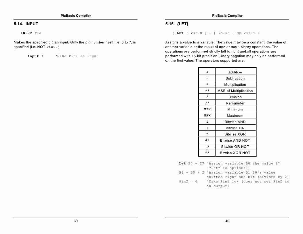
on the first value. The operators supported are:
+ Addition
- Subtraction
* Multiplication
** MSB of Multiplication
/ Division
// Remainder
MIN Minimum
MAX Maximum
& Bitwise AND
| Bitwise OR
^ Bitwise XOR
&/ Bitwise AND NOT
|/ Bitwise OR NOT
^/ Bitwise XOR NOT
Let B0 = 27 ‘Assign variable B0 the value 27
(“Let” is optional)
B1 = B0 / 2 ‘Assign variable B1 B0's value
shifted right one bit (divided by 2)
Pin2 = 0 ‘Make Pin2 low (does not set Pin2 to
an output)

PicBasic Compiler
41
5.15.1. Multiplication
PBC performs 16x16 multiplication. The '* ' operator returns the lower 16
bits of the 32-bit result. This is the typical multiplication found in most
programming languages. The '** ' operator returns the upper 16 bits of
the 32-bit result. These two operators can be used in conjunction to
perform 16x16 multiplication to produce 32-bit results.
W1 = W0 * 1000 ‘Multiply value in W0 by 1000
and place the result in W1
W2 = W1 ** W0 ‘Multiply W1 by W0 and place
the high order 16 bits (which
may be 0) in W2
5.15.2. Bitwise NOT Operators
Along with the normal bitwise binary operators (AND, OR, XOR), PBC also
supports NOT versions. These versions perform a bitwise complement on
the right-hand value prior to performing the operation.
B3 = B3 &/ %11110000 ‘Same as B3 = B3 &
%00001111
PicBasic Compiler
42
5.16. LOOKDOWN
LOOKDOWN Search, ( Constant{, Constant} ), Var
The LOOKDOWN statement searches a list of Constant values for the
presence of the Search value. If found, the index of the matching
constant is stored in Var. Thus, if the value is found first in the list, Var is
set to zero. If second in the list, Var is set to one. And so on. If not found,
no action is taken and Var remains unchanged.
The constant list can be a mixture of numeric and string constants. Each
character in a string is treated as a separate constant with the character's
ASCII value.
Serin 1,N2400,B0 ‘Get hexadecimal
character from Pin1
serially
Lookdown B0,(“0123456789ABCDEF”),B1 ‘Convert
hexadecimal
character in
B0 to
decimal
value B1
Serout 0,N2400,(#B1) ‘Send decimal value to
Pin0 serially

PicBasic Compiler
43
5.17. LOOKUP
LOOKUP Index, ( Constant{, Constant} ), Var
The LOOKUP statement can be used to retrieve values from a table of
constants. If Index is zero, Var is set to the value of the first Constant.
If Index is one, Var is set to the value of the second Constant. And so
on. If Index is greater than or equal to the number of entries in the
constant list, no action is taken and Var remains unchanged.
The constant list can be a mixture of numeric and string constants. Each
character in a string is treated as a separate constant equal to the
character's ASCII value.
For B0 = 0 to 5 ‘Count from 0 to 5
Lookup B0,(“Hello!”),B1 ‘Get character
number B0 from
string to variable
B1
Serout 0,N2400,(B1) ‘Send character in
B1 to Pin0
serially
Next B0 ‘Do next character
PicBasic Compiler
44
5.18. LOW
LOW Pin
Makes the specified pin output low. The pin is automatically made an
output pin. Only the pin number itself, i.e. 0 to 7, is specified (i.e. NOT
Pin0.)
Low 0 ‘Make Pin0 an output and set it low (0
volts)

PicBasic Compiler
45
5.19. NAP
NAP Period
Places PICmicro MCU in low power mode for short periods of time.
During this NAP, power consumption is reduced to minimum. The listed
periods are only approximate because the timing is derived from the
W atchdog Timer which is R/C driven and varies greatly from chip to chip
and over temperature:
Period Delay (Approx.)
0 18 mSec
1 36 mSec
2 72 mSec
3 144 mSec
4 288 mSec
5 576 mSec
6 1.152 Sec
7 2.304 Sec
Nap 7 ‘Low power pause for about 2.3 seconds
PicBasic Compiler
46
5.20. OUTPUT
OUTPUT Pin
Make the specified pin an output. Only the pin number itself, i.e. 0 to 7, is
specified (i.e. NOT Pin0.)
Output 0 ‘Make Pin0 an output

PicBasic Compiler
47
5.21. PAUSE
PAUSE Period
Pauses the program for Period milliseconds. Period is 16-bits, so
delays can be up to 65,535 milliseconds (a little over a minute). Unlike
the other delay functions (NAP and SLEEP), PAUSE doesn't put the
PICmicro MCU into low power mode. Thus, PAUSE consumes more
power but is also more accurate. It has the same accuracy as the system
clock.
Pause 1000 ‘Delay for 1 second
PicBasic Compiler
48
5.22. PEEK
PEEK Address, Var
Reads the PICmicro MCU register at the specified Address and stores
the result in Var. Special PICmicro MCU features such as A/D converters
and additional I/O ports may be read using PEEK. PEEK is a PicBasic
Compiler statement and is not supported on the BASIC Stamp.
PEEK and POKE allow direct access to all of the registers on a PICmicro
MCU including PORTA, PORTB, PORTC, PORTD, PORTE and their
associated data direction (TRIS) registers. PEEK and POKE operate on
all of the bits, i.e. the entire byte, of the particular register at once. W hen
you POKE data to PORTA, the entire port is updated, not just one
individual bit.
If substantial individual bit manipulation is required, it is recommended
that those I/O functions be assigned to a pin on PORTB and less
demanding byte access be left to the other I/O ports. Alternatively
variable B0 allows manipulation of its individual bits. It can first be set up
as desired and then POKEd to PORTA, for example, to ease bit
manipulation. Following are examples of this technique. This technique
may be used with any PICmicro MCU register.
‘ Read PortA bits using intermediate variable B0
Symbol PortA = 5 ‘Define PortA register
location
Symbol TrisA = $85 ‘Define PortA direction
register location
Poke TrisA,255 ‘Make all PortA pins
inputs
loop: Peek PortA,B0 ‘Get current PortA pin
states to variable B0
If Bit0 = 1 Then zerohigh ‘Jump to
label
zerohigh if
Bit0 (RA0)
is high
PicBasic Compiler
49
If Bit1 = 0 Then onelow ‘Jump to label
onelow if Bit1
(RA1) is low
Goto loop ‘Go check some more
zerohigh: High 0 ‘Set Pin0 (RB0) high
Goto loop ‘Go do some more
onelow: Low 1 ‘Set Pin1 (RB1) low
Goto loop ‘Go do some more
End
‘ Set PortA bits using intermediate variable B0
Symbol PortA = 5 ‘Define PortA register
location
Symbol TrisA = $85 ‘Define PortA direction
register location
Poke TrisA,0 ‘Make all PortA pins
outputs
Peek PortA,B0 ‘Get current PortA pin
states to variable B0
Bit1 = 1 ‘Set Bit1 in B0 which will
become PortA pin 1 high
Bit3 = 0 ‘Set Bit3 in B0 which will
become PortA pin 3 low
‘Bit0, 2 and 4 will remain
unchanged
Poke PortA,B0 ‘Send the new byte to
PortA to complete the
change
End
PicBasic Compiler
50
5.23. POKE
POKE Address, Value
W rites Value to the PICmicro MCU register at the specified Address.
Special PICmicro MCU features such as A/D converters and additional
I/O ports may be written using POKE. POKE is a PicBasic Compiler
statement and is not supported on the BASIC Stamp. (See PEEK for
more information.)
Poke $85,0 ‘Write 0 to register hexadecimal 85
(Sets PortA to all outputs)

PicBasic Compiler
51
5.24. POT
POT Pin, Scale, Var
Reads a potentiometer (or some other resistive device) on Pin. Pins are
numbered 0 to 7.
The resistance is measured by timing the discharge of a capacitor
through the resistor (typically 5K to 50K). Scale is used to adjust for
varying R/C constants. For larger R/C constants, Scale should be set
low (a minimum value of one). For smaller R/C constants, Scale should
be set to its maximum value (255). If Scale is set correctly, Var should
be zero near minimum resistance and 255 near maximum resistance.
Scale must be determined experimentally. To do so, set the device
under measure to maximum resistance and read it with Scale set to
127. Adjust Scale until the Pot command returns 254. If 255, decrease
the scale. If 253 or lower, increase the scale. (NOTE: This is the same
type of process performed by the Alt-P option of the BS1 environment).
Use the following code to automate the process. Make sure that you set
the pot to maximum resistance.
For B1 = 1 To 255
POT 0,B1,B0
If B0 > 253 Then calibrated
Next B1
Serout 2,0,("Increase R or C.",10,13)
End
calibrated:
Serout 2,0,("Scale= ",#B1,10,13)
PicBasic Compiler
52
5.25. PULSIN
PULSIN Pin, State, Var
Measures pulse width in 10 uSec units on Pin. If State is zero, the
width of a low pulse is measured. If State is one, the width of a high
pulse is measured. The measured width is placed in Var, which can take
measurements from 10 uSec to 655,350 uSec for 16-bit variables. If the
pulse edge never happens or the width of the pulse is too great to
measure, Var is set to zero. If an 8-bit variable is used, only the LSB of
the 16-bit measurement is used. Pins are numbered from 0 to 7.
Pulsin 4,1,W3 ‘Measure high pulse on Pin4
and place width * 10uSec in W3

PicBasic Compiler
53
5.26. PULSOUT
PULSOUT Pin, Period
Generates a pulse on Pin of specified Period in 10 uSec units. Since
Period is 16-bits, pulses of up to 655,350 uSec can be generated. The
pulse is generated by toggling the pin twice, thus the initial state of the pin
determines the polarity of the pulse. The pin is automatically made an
output pin. Pins are number 0 to 7.
Pulsout 5,100 ‘Send a pulse 1mSec long to
Pin5
PicBasic Compiler
54
5.27. PWM
PWM Pin, Duty, Cycle
Outputs PW M pulse train on Pin. Each cycle of PW M consists of 256
steps. The Duty cycle for each PW M cycle ranges from 0 (0%) to 255
(100%). This PW M cycle is repeated Cycle times. Pins are numbered
from 0 to 7.
The pin is made an output just prior to pulse generation and reverts to an
input after generation stops. This allows a simple R/C circuit to be used
as a simple D/A converter:
Pwm 7,127,100 ‘Send a 50% duty cycle PWM
signal out Pin7 for 100 cycles

PicBasic Compiler
55
5.28. RANDOM
RANDOM Var
Performs one iteration of pseudo-randomization on Var. Var must be a
16-bit variable. (NOTE: PBC does not support the use of the PORT
variable with the RANDOM statement). The pseudo-random algorithm used
has a walking length of 65535 (only zero is not produced).
Random W4 ‘Get a random number to W4
PicBasic Compiler
56
5.29. READ
READ Address, Var
Reads the EEPROM byte at the specified Address and stores the result
in Var. If Address is 255 and the device is a PIC16C84, 16F627, 628,
83 or 84, Var is assigned the number of EEPROM bytes available.
Address 255 is not valid for 16F87x devices. This instruction may only
be used with a PICmicro MCU that has an on-chip EEPROM data area
such as the PIC16C84, 16F62x, 8x and 87x.
Read 5,B2 ‘Put the value at EEPROM location 5
into B2
PicBasic Compiler
57
5.30. RETURN
RETURN
Returns from subroutine. RETURN resumes execution at the statement
following the GOSUB which called the subroutine.
Gosub sub1 ‘Go to subroutine labeled sub1
...
sub1: Serout 0,N2400,(“Lunch”) ‘Send “Lunch” out
Pin0 serially
Return ‘Return to main program after
Gosub
PicBasic Compiler
58
5.31. REVERSE
REVERSE Pin
If the pin is an input, it is made an output. If the pin is an output, it is made
an input. Pins are numbered 0 to 7.
Output 4 ‘Make Pin4 an output
Reverse 4 ‘Change Pin4 to an input

PicBasic Compiler
59
5.32. SERIN
SERIN Pin, Mode,{ ( Qual{, Qual} ), } Item{, Item}
Receives one or more items on Pin in standard asynchronous format
using 8 data bits, no parity and one stop bit. Mode is one of the following:
Symbol Value Baud Rate Mode
T2400 0 2400
TTL TrueT1200 1 1200
T9600 2 9600†
T300 3 300
N2400 4 2400
TTL InvertedN1200 5 1200
N9600 6 9600†
N300 7 300
† 9600 baud is an addition to the PicBasic Compiler and is not available
on the BASIC Stamp I.
The list of data items to be received may be preceded by one or more
qualifiers enclosed within parenthesizes. SERIN must receive these bytes
in exact order before receiving the data items. If any byte received does
not match the next byte in the qualifier sequence, the qualification
process resets (i.e. the next received byte is compared to the first item in
the qualifier list). A Qualifier can be a constant, variable or a string
constant. Each character of a string is treated as an individual qualifier.
Once the qualifiers are satisfied, SERIN begins storing data in the
variables associated with each Item. If the variable name is used alone,
the value of the received ASCII character is stored in the variable. If
PicBasic Compiler
60
variable is preceded by a pound sign ( # ), then SERIN converts a
decimal value in ASCII and stores the result in that variable. All non-digits
received prior to the first digit of the decimal value are ignored and
discarded. The non-digit character which terminates the decimal value is
also discarded.
W hile single-chip RS-232 level converters are common and inexpensive,
the excellent I/O specifications of the PICmicro MCU allow most
applications to run without level converters. Rather, inverted input
(N9600..N300) can be used is conjunction with a current limiting resistor.
Serin 1,N2400,(“A”),B0 ‘Wait until the
character “A” is
received serially on
Pin1 and put next
character into B0

PicBasic Compiler
61
5.33. SEROUT
SEROUT Pin, Mode, ( Item{, Item} )
Sends one or more items to Pin is standard asynchronous format using
8 data bits, no parity and one stop. Mode is one of the following:
Symbol Value Baud Rate Mode
T2400 0 2400
TTL TrueT1200 1 1200
T9600 2 9600†
T300 3 300
N2400 4 2400
TTL InvertedN1200 5 1200
N9600 6 9600†
N300 7 300
OT2400 8 2400
Open DrainOT1200 9 1200
OT9600 10 9600†
OT300 11 300
ON2400 12 2400
Open SourceON1200 13 1200
ON9600 14 9600†
ON300 15 300
† 9600 baud is an addition to the PicBasic Compiler and is not available
on the BASIC Stamp I.
SEROUT supports three different data types which may be mixed and
matched freely within a single SEROUT statement.
1) A string constant is output as a literal string of characters.
2) A numeric value (either a variable or a constant) will send the
corresponding ASCII character. Most notably, 13 is carriage
return and 10 is line feed.
3) A numeric value preceded by a pound sign ( # ) will send the
PicBasic Compiler
62
ASCII representation of its decimal value. For example, if W0 =
123, then #W0 (or #123) will send '1 ', '2 ', '3 '.
W hile single-chip RS-232 level converters are common and inexpensive,
thanks to current RS-232 implementation and the excellent I/O
specifications of the PICmicro MCU, most applications don't require level
converters. Rather, inverted TTL (N300..N9600) can be used. A current
limiting resistor is suggested (RS-232 is suppose to be short-tolerant).
Serout 0,N2400,(#B0,10) ‘Send the ASCII value of
B0 followed by a
linefeed out Pin0
serially

PicBasic Compiler
63
5.34. SLEEP
SLEEP Period
Places PICmicro MCU in low power mode for Period seconds. Period
is 16-bits, so delays can be up to 65,535 seconds (just over 18 hours).
SLEEP uses the W atchdog Timer to periodically wake up to see if the
Period has expired so its resolution is the maximum timeout for the
W atchdog Timer, 2.3 seconds.
Sleep 60 ‘Sleep for 1 minute
PicBasic Compiler
64
5.35. SOUND
SOUND Pin, ( Note, Duration{, Note, Duration} )
Generates tone and/or white noise on the specified Pin. Note 0 is
silence. Notes 1-127 are tones. Notes 128-255 are white noise. Tones
and white noises are in ascending order (i.e. 1 and 128 are the lowest
frequencies, 127 and 255 are the highest). Duration is 0-255 and
determines how long the Note is played. Note and Duration needn't
be constants. Pins are numbered 0 to 7.
SOUND outputs TTL-level square waves. Thanks to the excellent I/O
characteristics of the PICmicro MCU, a speaker can be driven through a
capacitor. Piezo speakers can be driven directly.
Sound 7,(100,10,50,10) ‘Send 2 sounds
consecutively to Pin7

PicBasic Compiler
65
5.36. TOGGLE
TOGGLE Pin
Inverts the state of the specified pin. The pin is automatically made an
output pin. Pins are numbered 0 to 7.
Low 0 ‘Start Pin0 as low
Toggle 0 ‘Change state of Pin0 to high
PicBasic Compiler
66
5.37. WRITE
WRITE Address, Value
W rites byte Value to the EEPROM at the specified Address. This
instruction may only be used with a PICmicro MCU that has an on-chip
EEPROM data area such as the PIC16C84, 16F62x, 8x and 87x.
Write 5,B0 ‘Send value of B0 to EEPROM location
5
PicBasic Compiler
67
6. Structure of a Compiled Program
PBC is designed to be easy to use. Programs can be compiled and run
with little thought to PBC's internal workings. Some people, however, only
have confidence in a product when they understand its internal workings.
Others are just plain curious.
This section is for them. It describes the output generated by PBC and
gives some idea of exactly what is going on.
6.1. Target (PICmicro MCU) Specific Header (B##.INC)
The first thing a PBC generated program does is define the symbol PBCX
to be 1 if PBC extensions are enabled, or 0 if PBC extensions are
disabled (-C option). This allows the library to selectively define additional
variables and functions needed for PBC extensions.
Next, a target specific header file is included. By default, this file is
B16F84.INC, although this can be changed using the -P option.
This header is, in turn, responsible for including (via MACLIB) the
processor specific header supplied with PM. The PM header, in turn,
defines all the processor specific information needed to assemble
programs for that PICmicro MCU.
The B##.INC header then uses the DEVICE pseudo-op to set the
processor's fuses. For NAP and SLEEP to work, the W atchdog Timer
must be enabled. The oscillator must also be set appropriately. Other
fuse positions can be set at the user's discretion. See the Microchip data
sheet for the particular device for information about the configuration
fuses.
The DATA pseudo-op is next used to select the data segment as the
current segment. It should also place the load pointer at the base of
usable RAM in the target processor. In the case of a PIC16Cxxx, this will
either be 0Ch or 20h. Selecting one of these addresses is important
because PBC's internal bit numbering scheme relies on selecting one of
these two addresses.
PicBasic Compiler
68
The header should then execute NLIST to disable listing. This hides
tedious, uninteresting and unchanging implementation details in
PBH.INC.
Then PBH.INC is included. If desired, macro and bit addresses defined in
PBH.INC can be overridden by being defined here.
W hen PBH.INC is done, listing is enabled and the code segment is
selected. At this point, any target specific library routines should be
added. Since these routines must be assembled before the user's code is
assembled, they must assemble unconditionally (unlike the normal library
routines). Hence, such target specific routines should be as brief as
possible.
The last thing left to do is define the main label, which is where the user's
code will start execution.
6.2. PBH.INC
PBH.INC first defines user variables in the data segment. This is followed
by the definition of working and temporary registers used by PBC's
libraries. User variables can occupy up to 80 bytes of memory unless the
-C option is used, in which case only 14 bytes are used. W orking
variables and temporary registers occupy another 13-16 bytes.
PINx, DIRx, and other bit locations are numbered. All bits of interest
(PORT, TRIS, and the bits of W0) need to be spanned by an 8-bit value in
order to take best advantage of the W register. Since normal PICmicro
MCU numbering requires 11 bits, a custom system was developed. Its
details are uninteresting, but it is important to understand that PBC bit
numbers need to be converted before use and cannot be used verbatim
in an assembly language subroutine.
A number of macros are defined. Some are simple utility macros. Some
perform the bit mapping mentioned earlier. And some macros access the
PINS and DIRS registers. These are particularly interesting since they
can be overridden by definitions in B##.INC.
The code segment is then selected and startup code is generated. This is
followed by a set mandatory library routines. The FW@Pin and FW@Mask

PicBasic Compiler
69
functions are responsible for the run time mapping of PBC bit numbers
onto the FSR and W registers.
6.3. PBC Generated Code
B##.INC and PBH.INC have now laid all the ground work for the
compiled code. The code segment is the current segment and the load
pointer is set to main, the place where the user's code begins execution.
After the user's code is assembled, PBC's library PBL.INC is included.
6.4. PBL.INC
PBL.INC contains library support routines. Most of the routines
corresponding to PBC statements end in the '@ ' character. Block
comments indicate each routine's functionality. Routines are ordered
such that every routine in the library is only dependent on routines which
occur later in the library. Each routine is conditionally assembled only if it
is explicitly referenced (via the REF operator). In this way, only needed
library routines are actually assembled.
The first module in PBL.INC is end@. Unlike other modules in the library,
end@ is always assembled. This simulates the END statement implicitly at
the end of each PBC program.
PicBasic Compiler
70

PicBasic Compiler
71
7. Other PicBasic Considerations
7.1. How Fast is Fast Enough?
The PicBasic Compiler generates programs intended to be run on a
PICmicro MCU with a 4MHz crystal or ceramic resonator. All of the time
sensitive instructions assume a 1 microsecond instruction time for their
delays. This allows a Pause 1000, for example, to wait 1 second and
the SERIN and SEROUT command’s baud rates to be accurate.
There are times, however, when it would be useful to run the PICmicro
MCU at a frequency other than 4MHz. Even though the compiled
programs move along at a pretty good clip, it might be nice to run them
even faster. Or maybe it is desirable to do serial input or output at 19,200
baud rather than the current top speed of 9600 baud.
PicBasic Compiler programs may be run at clock frequencies other than
4MHz if you pay attention to what happens to the time dependent
instructions. If you wish to run the serial bus at 19,200 as described
above, you would simply clock the PICmicro MCU with an 8MHz crystal
rather than a 4MHz crystal. This, in effect, makes everything run twice as
fast, including the SERIN and SEROUT commands. If you tell SERIN or
SEROUT to run at 9600 baud, the doubling of the crystal speed will double
the actual baud rate to 19,200 baud.
However, keep in mind commands such as PAUSE and SOUND will also
run twice as fast. The Pause 1000 mentioned above would only wait
half a second with an 8MHz crystal before allowing program execution to
continue.
This technique may also be used to enhance the resolution of the
PULSIN and PULSOUT instructions. At 4MHz these instructions operate
with a 10 microsecond resolution. If a 20MHz crystal is used, the
resolution is increased 5 times to 2 microseconds. There is a tradeoff
however. The pulse width is still measured to a 16-bit word variable.
W ith a 2 microsecond resolution, the maximum measurable pulse width
would be 131,070 microseconds.
Going the other direction and running with a 32.768Khz oscillator is
problematic. It may be desirable to attempt this for reduced power
consumption reasons and it will work to some extent. The SERIN and
PicBasic Compiler
72
SEROUT commands will be unusable and the W atchdog Timer may cause
the program to restart periodically. Experiment to find out if your
particular application is possible at this clock speed. It doesn’t hurt to try.
The time dependent instructions are I2CIN, I2COUT, PAUSE, POT,
PULSIN, PULSOUT, PWM, SERIN, SEROUT, SLEEP, and SOUND. It is
possible to modify the actual library routines to maintain proper
instruction timing at clock speeds other than 4MHz, although with some
functions a fair bit of effort may be required.
7.2. Assembly Language
Assembly language routines can be a useful adjunct to a PicBasic
Compiler program. W hile in general most tasks can be done completely
in PicBasic, there are times when it might be necessary to do a particular
task faster, or using a smaller amount of code space, or just differently
than the compiler does it. At those times it is useful to have the
capabilities of an in-line assembler.
It can be beneficial to write most of a program quickly using the PicBasic
language and then sprinkle in a few lines of assembly code to increase
the functionality. This additional code may be inserted directly into the
PicBasic program, added to the main library, or included as another file.
7.2.1. Programming in Assembly Language
PBC programs may contain in-line assembly; one or more lines of
assembly code preceded by the ASM keyword and ended by the ENDASM
keyword. Both keywords appear on their lines alone.
The lines of assembly are copied verbatim to the assembly output file.
This allows the PBC program to use all of the facilities of PM, the
PICmicro Macro Assembler. This also, however, requires that the
programmer have some familiarity with the PBC libraries. PBC’s
notational conventions are similar to other commercial compilers and
should come as no shock to programmers experienced enough to
attempt in-line assembly.
All symbol names defined in a PBC program are similarly defined in
assembly, but with the name preceded with an underscore ( _ ). This
allows access to user variables, constants, and even labeled locations, in

PicBasic Compiler
73
assembly. Similarly, system variable (such as W0) names are also
preceded by underscores (such as _W0).
Thus, any name defined in assembly starting with an underscore has the
possibility of conflicting with a PBC generated symbol. If conflict is
avoided, can these underscored assembly values be accessed from
PBC? No. Remember, the underscored names generated by PBC are
only shadows of the actual information defined in the compiler. Since in-
line assembly is copied directly to the output file and not processed by
the compiler, the compiler not only lacks any type or value information
about assembly symbols, it is completely unaware that they exist. If
variables are to be shared between assembly and PBC, either use
predefined system variables or define the variables in PBC.
Just as underscored symbols have possible conflicts, so do symbols not
starting with underscores. The problem is internal library variables.
Luckily, most library variables contain an '@ ' or make reference to one of
the working registers (such as R0). Avoiding such names should be
reduce problems. If you should have a name collision, the compiler will
report the duplicate definitions as an error.
7.2.2. Assembly Language Examples
To write a byte to PORTA in PicBasic you could simply:
Poke 5,B0 ‘Send whatever is in variable
B0 to PortA (register 5)
But for code speed and size reasons you might write:
asm ‘The following code is written
in assembler
clrb RP0 ;Make sure we’re pointing to
the proper register page
mov 5,_B0 ;Send whatever is in variable
B0 to PortA (register 5)
endasm
This code takes 3 words of code space and runs in 3 microseconds (with
a 4MHz oscillator) as opposed to the PicBasic statement which takes up
a little more code space but takes several microseconds longer to
PicBasic Compiler
74
execute. (The clrb RP0 isn’t strictly necessary. The compiler normally
clears that bit before returning from a library routine. But better safe...)
Note that in the assembly example above the variable B0 was preceded
by an underscore ( _ ). By convention, PicBasic labels and variables that
are accessed in assembler must be preceded by an underscore. This is
to keep lower level label assignments from interfering with PicBasic
labels and variables.
You might also note that the comment delimiter changed from the single
quote (‘) in PicBasic to the semi-colon (;) after the ASM command.
Unfortunately, each language’s syntax has a different requirement for this
character.
Larger assembly language routines may be included in your program or
in a separate file. If a routine is used by only one particular PicBasic
program, it would make sense to include the assembler code within the
PicBasic file. This routine can then be accessed using the CALL
command.
‘PicBasic example program with embedded assembly
language subroutines
loop: For B0 = 0 To 255 ‘Count up B0 in a
For..Next loop
Call shiftout ‘Call assembly routine
to shift B0 out PortA
Next B0 ‘Do next count
Call shiftin ‘Shift in a byte from
PortA to B0
Serout 0,N2400,(B0) ‘Send the byte out
serially on Pin0
Goto loop ‘Go do it all again
End
asm ‘Assembly language code
follows
_shiftout mov T0,#8 ;Setup temporary variable with
bit count

PicBasic Compiler
75
soloop rr _B0 ;Get low order bit of data
byte to carry
jnc solow ;If no carry then data bit
should be low
setb PortA.0 ;Otherwise set data bit
high
skip ;Skip over next instruction
solow clrb PortA.0 ;Set data bit low
setb PortA.1 ;Toggle clock high
clrb PortA.1 ;Toggle clock back low
djnz T0,soloop ;Loop to do all 8 bits
return ;Go back to main program when
done
_shiftin mov T0,#8 ;Setup temporary variable with
bit count
siloop setb PortA.1 ;Toggle clock high
clrb PortA.1 ;Toggle clock back low
clc ;Preset carry to off
snb PortA.0 ;If data bit is low then
skip over next
instruction
stc ;Else set carry to on
rl _B0 ;Roll bit into result byte B0
djnz T0,siloop ;Loop to do all 8 bits
goto done ;Exit through library
routine Done
endasm ‘End of assembly language code
Don’t forget to put an END or GOTO or some other mechanism at the end
of your PicBasic code to keep the processor from “falling into” your
assembler subroutines upon execution.
Also note that the function terminates by jumping to DONE rather than
simply returning. Returning would be fine, but the DONE function
performs other housecleaning needed by PBC (resetting the RP0 bit and
hitting the W atchdog). W is not affected by done.
If the assembler routine is destined to be used by several PicBasic
programs, it makes sense to put it into its own separate text file and
simply tell the assembler to INCLUDE this file.
PicBasic Compiler
76
‘PicBasic example program with assembler code included
in a separate file
loop: For B0 = 0 To 255 ‘Count up B0 in a For..Next
loop
Call shiftout ‘Call assembly routine to
shift B0 out PortA
Next B0 ‘Do next count
Call shiftin ‘Shift in a byte from PortA to
B0
Serout 0,N2400,(B0) ‘Send the byte out
serially on Pin0
Goto loop ‘Go do it all again
End
asm ‘Assembly language code
follows
include “shift.inc” ;Assembly code
will be inserted
here
endasm
The third option for using assembly code with a PicBasic program is to
add the code right into the PBH.INC or PBL.INC files. These files are
automatically included by the compiler.
This is the avenue most fraught with danger. These files are built in a
particular manner and caution should be exercised before changing
them. Also, as updates to the compiler are released, these files will
change and your routines would need to follow the changes. If this is the
path of choice, be sure to make copies of the original files and only work
from those copies.
7.2.3. Placement of In-line Assembly
PBC statements execute in order of appearance in the source. The first
executable line that appears is where the program starts execution. That
statement literally appears in memory right behind the controller’s startup
code. Similarly, the END implicit at the end of every PBC program is

PicBasic Compiler
77
accomplished by having the code for the END function appear first and
unconditionally in the library. It appears in memory directly behind the
user's last statements. This method saves two unneeded jumps and
everything normally works out all right.
The tendency of programmers is to place their own library functions
written using the inline assembler either before or after their code. In light
of the above explanation, this could create some obvious problems. If
they appear early in the program, the assembly routines execute prior to
any PBC instructions (some programmers will invariably exploit this
feature). If they appear at the tail of the program, execution which "falls
off the end" of the PBC statements may mysteriously find themselves
unintentionally executing assembly routines.
W hat should you do? Simple. Unlike a hosted system (such as the PC or
the Mac), there is little reason for an embedded system to terminate.
Thus, place your assembly routines after your PBC code. If you need to
terminate your program, explicitly place an END statement at the end of
your code rather then relying on the implicit END.
7.2.4. The PICmicro Macro Assembler
The PICmicro Macro Assembler (PM) included with the PicBasic
Compiler can use “8051 style” mnemonics or the Microchip mnemonics.
The included header files which define the register and bit names,
however, are in the 8051 form. This format includes the register name
and bit name into one symbol. This makes it quicker and easier to write
the code but also makes it somewhat incompatible with Microchip code
that may be scattered through their data books.
It is a fairly simple matter to convert these symbols as they are typed in
or use your text editor’s or word processor’s search and replace function
to change them.
For example, if the Microchip code says:
bsf status,rp0 ;set bit rp0
the equivalent PM code would be:
bsf rp0 ;set bit rp0
PicBasic Compiler
78
The reason behind this change is that the symbol RP0 is defined to
already include the information that it is in the Status register. See the
PM include files, P16F8x.INC for example, for a complete list of these
symbol definitions for each PICmicro MCU.
The assembler instruction set is listed in the appendix of this document.
For complete information on the PICmicro Macro Assembler, see the
PM.TXT file on disk.
7.3. Interrupts
Interrupts can be a scary and useful way to make your program really
difficult to debug.
Interrupts are triggered by hardware events, either an I/O pin changing
state or a timer timing out and so forth. If enabled (which by default they
aren’t), an interrupt causes the processor to stop whatever it is doing and
jump to a specific routine in the PICmicro MCU called an interrupt
handler.
Interrupts are not for the faint of heart. They can be very tricky to
implement properly, but at the same time they can provide very useful
functions. For example, an interrupt could be used to buffer serial input
data behind the scenes while the main PicBasic program is off doing
something else. (This particular usage would require a PICmicro MCU
with a hardware serial port.)
The PicBasic Compiler does not directly support interrupts, but that does
not mean they cannot be used. The PicBasic library routines are not
reentrant. This means that you cannot execute PicBasic statements from
within an interrupt handler - the interrupt handler must be written in
assembly language. This statement alone should be enough to strike
fear into the heart of the BASIC programmer.
However, if you just gotta do it, here are some hints on how to go about
it.
W hen an interrupt occurs, the PICmicro MCU stores the address of the
next instruction it was supposed to execute on the stack and jumps to
location 4. The first thing this means is that you need an extra location
on the PICmicro MCU stack, which is only 8 deep to begin with.

PicBasic Compiler
79
The PicBasic library routines can use up to 4 stack locations themselves.
The remaining 4 are reserved for CALLs and nested BASIC GOSUBs.
You must make sure that your GOSUBs are only nested 3 deep at most
with no CALLs within them in order to have a stack location available for
the return address. If your interrupt handler uses the stack (by doing a
Call itself for example), you’ll need to have additional stack space
available.
Once you have dealt with the stack issues, it gets even trickier. Since
you have no idea of what the processor was doing when it was
interrupted, you have no idea of the state of the W register, the Status
flags, PCLATH or even what register page you are pointing to. If you
need to alter any of these, and you probably will, you must save the
current values so that you can restore them before allowing the
processor to go back to what it was doing before it was so rudely
interrupted. This is called saving and restoring the processor context.
If the processor context is not left exactly the way you found it, all kinds of
subtle bugs and even major system crashes can and will occur.
This of course means that you cannot even safely use the compilers
internal variables for storing the processor context. You cannot tell which
variables are in use by the library routines at any given time.
W e have reserved three internal variables strictly for use by an interrupt
handler: I0, I1, and I2 (Only I0 has a real RAM location on a
PIC16C84. Use a PICmicro MCU with more RAM such as a PIC16F84
for access to the additional locations.) If you require more than these
variables, you can reserve as many of the user variables (B0, B1, ...) as
you like by simply not using them in your PicBasic program. You may
use these locations to store W, the Status register, or any other register
that may need to be altered by the interrupt handler.
The interrupt routine should be as short and fast as you can possibly
make it. If it takes too long to execute, the W atchdog Timer could timeout
and really make a mess of things. Perhaps the most useful function
would be to simply set a PicBasic variable to a particular value when an
interrupt occurs. W hen the PicBasic program sees this value, it knows
an interrupt has occurred and it can take the appropriate actions.
PicBasic Compiler
80
The interrupt handler itself may be placed in the file PBH.INC in the INC
subdirectory. Near the end of the file is the label Start. This is where
the PICmicro MCU will start executing code on reset, location 0. A few
lines down is a section of code that has been commented out. If this
code is uncommented, it will enable you to insert your interrupt handler at
location 4. Place your assembly language interrupt handler routine after
the ORG 4. The routine should end with an RETI instruction to return
from the interrupt and allow the processor to pick up where it left off in
your PicBasic program.
From this point you are on your own. If you follow the above
suggestions, your interrupt routine should be able to coexist peacefully
with your PicBasic program.
Definitely, definitely, definitely refer to the Microchip PICmicro MCU data
books for additional information on how to use interrupts. They give
examples of storing processor context as well as all the necessary
information to enable a particular interrupt. This data is invaluable to your
success.
7.4. Life After 2K
W hen a PicBasic program grows longer than 2K (which is a pretty big
program), problems will occur. PICmicro MCU instructions such as Call
and Goto only have enough bits within them to address 2K of program
space. To get to code outside the 2K boundary, the PCLATH register
must be set before each Call or Goto.
In the interest of minimizing program size, the PicBasic Compiler makes
no effort to address this problem. The 2K boundary presents a problem
to PICmicro MCU programming in any language; assembly, C, or
PicBasic.
If it is necessary for a program to be longer than 2K, the .ASM file the
compiler generates can be “fixed-up” and then assembled after setting
PCLATH before and after the appropriate instructions. It would probably
be best to use memory beyond 2K for large table storage to keep “fix-
ups” to a minimum.
See the Microchip PICmicro MCU data books for more information on
PCLATH and address sizes.

PicBasic Compiler
81
8. Compiler / Stamp Differences
Every effort has been made to assure that programs compiled by PBC
execute as they would on a BASIC Stamp I. Most programs will compile
and execute without error.
But, just as with all system which promise "compatibility", there are
always some slight differences. Some are due to improvements in code
executed directly on the PICmicro MCU rather than via the Stamp chip
set. Others are the result of the fact that the BASIC Stamp is a closed
system and its internal operations are unknown. W hile the results tested
well, we can never be 100% sure.
The following sections discuss the implementation details of PBC
programs that might present problems. It is hoped that if you do
encounter problems, these discussions will help illuminate the differences
and possible solutions.
8.1. Execution Speed
The largest potential problem shared by both library routines and user
code is speed. W ithout the overhead of reading instructions from the
EEPROM, many PBC instructions (such as GOTO and GOSUB) execute
hundreds of times faster than their BASIC Stamp equivalents. W hile in
many cases this is a benefit, programs whose timing has been developed
empirically may experience problems.
The solution is simple - good programs don't rely on statement timing.
W henever possible, a program should use handshaking and other non-
temporal synchronization methods. If delays are needed, statements
specifically generating delays (PAUSE, NAP or SLEEP) should be used.
8.2. Digital I/O
Unlike the BASIC Stamp, PBC programs operate directly on the PORT
and TRIS registers. W hile this has speed and RAM/ROM size
advantages, there is one potential drawback.
Some of the I/O commands (TOGGLE and PULSOUT) perform read-
modify-write operations directly on the PORT register. If two such
PicBasic Compiler
82
operations are performed too close together and the output is driving an
inductive or capacitive load, it is possible the operation will fail.
Suppose, for example, that a speaker is driven though a 10uF cap (just
as with the SOUND command). Also suppose the pin is initially low and the
programmer is attempting to generate a pulse using TOGGLE statements.
The first command reads the pin's low level and outputs its complement.
The output driver (which is now high) begins to charge the cap. If the
second operation is performed too quickly, it still reads the pin's level as
low, even though the output driver is high. As such, the second operation
will also drive the pin high.
In practice, this is not much of a problem. And those commands designed
for these types of interfacing (SOUND and POT, for example) have built-in
protection. This problem is not specific to PBC programs. This is a
common problem for PICmicro MCU (and other microcontroller)
programs and is one of the realities of programming hardware directly.
8.3. Missing PC Interface
Since PBC generated programs run directly on a PICmicro MCU, there is
no need for the Stamp's PC interface pins (PCO and PCI). The lack of a
PC interface does introduce some differences.
W ithout a PC, there is no place to send debugging information. Thus,
while PBC parses PBASIC's DEBUG commands, it doesn't generate code.
W ithout the PC to wake the PICmicro MCU from the END statement, it
remains in low power mode until /MCLR is lowered or power is cycled.
8.4. BUTTON
PBC's BUTTON command requires the programmer to specify an 8-bit
variable to store the current repeat count. The BASIC Stamp will allow
the use of any type of variable. W ord variables work fine, although they
are wasteful. On the Stamp, programs using bit variables for the BUTTON
command will compile and run, but the command will not behave
correctly. PBC's BUTTON command will also work correctly with word
variables. It does, however, generate a compiler error when an attempt is
made to use BUTTON with a bit variable.

PicBasic Compiler
83
The faster execution of PBC programs may be a problem for the BUTTON
command. The BUTTON command samples the input only once per
execution. Debouncing is achieved by the delay introduced by other
Stamp overhead (such as fetching instructions from EEPROM). Thus, a
BUTTON command which is executed too frequently might not provide as
good a "debounce" in PBC programs as it does on the BASIC Stamp.
8.5. EEPROM, READ and WRITE
The BASIC Stamp allows EEPROM not used for program storage to
store non-volatile data. Since PBC programs execute directly from the
PICmicro MCU's ROM space, EEPROM storage must be implemented in
some other manner.
The PIC16C84, 16CF62x, 8x and 87x devices have from 64 to 255 bytes
of on-chip data EEPROM. PBC programs may use this for EEPROM
operations and fully supports PBASIC's EEPROM, READ and WRITE
commands. The PIC16F87x devices do not return the device size when
location 255 is read.
To access off-chip non-volatile data storage, the I2CIN and I2COUT
instructions have been added. These instructions allow 2-wire
communications with serial EEPROMs like Microchip Technology’s
24LC01B.
8.6. GOSUB/RETURN
The Stamp implements subroutines via the GOSUB and RETURN
statements. User variable W6 is used by the Stamp as a four nibble stack.
Thus, PBASIC programs may have up to 16 GOSUBs and subroutines can
be nested up to four levels deep.
The 14-bit core PICmicro MCUs have Call and Return instructions as well
as eight level stacks. PBC programs make use of these instructions and
use four levels of this stack, with the other four levels being reserved for
library routines. Thus, W6 is still available, subroutines may still be nested
up to four levels deep and the number of GOSUBs is limited only by the
PICmicro MCU's code space.
PicBasic Compiler
84
8.7. RANDOM
PBC's RANDOM statement takes any word variable as its parameter. The
PBC library routine takes the address of the 16-bit word to randomize as
its parameter. Since PBC doesn't implement the PORT register as a true
16-bit memory location, the statement RANDOM PORT will produce a
compilation error.
8.8. SERIN/SEROUT
SERIN and SEROUT have been altered to run up to 9600 baud from the
previous limit of 2400 baud. This has been accomplished by replacing the
little used rate of 600 baud with 9600 baud. Modes of T9600, N9600,
OT9600 and ON9600 may now be used.
600 baud is no longer available and will cause a compilation error if an
attempt is made to use it.
8.9. Low Power Instructions
W hen the W atchdog Timer time-out wakes a PICmicro MCU from sleep
mode, execution resumes without disturbing the state of the I/O pins. For
unknown reasons, when the BASIC Stamp resumes execution after a low
power instruction (NAP or SLEEP), the I/O pins are disturbed for
approximately 18 mSec. PBC programs make use of the PICmicro
MCU's I/O coherency. The NAP instruction does not disturb the I/O pins.
Similarly, the Stamp's SLEEP instruction disturbs the I/O pins every W DT
time-out period, approximately every 2.3 seconds. PBC's SLEEP
instructions only disturbs the I/O pins once every 10 minutes. This is
done while recalibrating the period of the W DT.
8.10. SLEEP
The Stamp's documentation indicates its SLEEP command is ~99.8%
accurate. This may be overly optimistic. First, the granularity of the
SLEEP command is determined by the W atchdog Timer period, which is
typically 2.3 seconds. This introduces an average error of about 1
second. Even without this granularity, SLEEP is only as accurate as the
PICmicro MCU's system clock. In the BS1, the oscillator is a resonator,
whose accuracy is +/-1%.

PicBasic Compiler
85
Ignoring these effects, there is still the larger problem of variability in the
PICmicro MCU's W atchdog Timer. The W DT is driven by an R/C
oscillator and the period varies greatly with temperature.
To eliminate this error, the W DT is calibrated in terms of the system
clocks. This is done by counting system clocks while waiting for the W DT
to time-out. This calibrated period is then used to decrement the desired
sleep period. This keeps SLEEP to within the accuracy of the system
clock (ignoring the granularity of the W DT).
PBC's SLEEP command performs this recalibration every 257 cycles or
about once every 10 minutes. It recalibrates for a full W DT period (about
2.3 seconds). This results in the PICmicro MCU being active about
0.38% of the time during the SLEEP command. For the PIC16F84 at
4MHz with the W DT enabled, Microchip specifies a typical operating
current of 1.8mA and a power down current of 40uA. Using these figures,
PBC's SLEEP draws approximately 47uA.
This is more than the current levels claimed by the BASIC Stamp. This is
due to the fact that the PIC16C5x family has a lower power-down current
consumption than members of the PIC16Cxxx family.
W ith all the above said, it has been determined that a calibrated SLEEP
command may not work properly on all PICmicro MCUs. During SLEEP
calibration, the PICmicro MCU is reset. Different devices respond in
different ways to this reset. Upon reset, many registers may be altered.
Notably the TRIS registers set all the PORT pins to inputs. The TRIS
state for PORTB is automatically saved and restored by the SLEEP
routine. Any other PORT directions must be reset by the user program
after SLEEP. Other registers may also be affected. See the data sheets
for a particular part for this information.
To get around potential problems, an uncalibrated version of SLEEP has
been created. This version does not cause a device reset so it has no
effect on any of the internal registers. All the registers, including PORT
direction, remain unchanged during and after a SLEEP instruction.
However, actual SLEEP times will no longer be as accurate and will vary
dependent on device particulars and temperature.
PicBasic Compiler
86
The uncalibrated version of SLEEP is now the default. To enable the
previous, calibrated version of SLEEP add the following lines to a PBC
program:
asm
SLEEPCAL = 1
endasm

PicBasic Compiler
87
Appendix A
Summary of Microchip Assembly Instruction Set
ADDLW kADDWF f, dANDLW kANDWF f, dBCF f, bBSF f, bBTFSC f, bBTFSS f, bCALL kCLRF fCLRWCLRWDTCOMF f, dDECF f, dDECFSZ f, dGOTO kINCF f, dINCFSZ f, dIORLW kIORWF f, dMOVF f, dMOVLW kMOVWF fNOPRETFIERETLW kRETURNRLF f, dRRF f, dSLEEPSUBLW kSUBWF f, dSWAPF f, dXORLW kXORWF f, d
b - bit addressd - destination: 0 = w, 1 = ff - register file addressk - literal constant
PicBasic Compiler
88
PicBasic Compiler
89
Appendix B
Contact Information
Technical support and sales may be reached at:
microEngineering Labs, Inc.
Box 60039
Colorado Springs CO 80960-0039
(719) 520-5323
(719) 520-1867 fax
http://www.melabs.com
email:[email protected]
PICmicro MCU data sheets and literature may be obtained from:
Microchip Technology Inc.
2355 W . Chandler Blvd.
Chandler AZ 85224-6199
(480) 792-7200
(480) 792-7277 fax
http://www.microchip.com
email:[email protected]

READ THE FOLLOWING TERMS AND CONDITIONS CAREFULLY
BEFORE OPENING THIS PACKAGE.
microEngineering Labs, Inc. ("the Company") is willing to license the
enclosed software to the purchaser of the software ("Licensee") only on
the condition that Licensee accepts all of the terms and conditions set
forth below. By opening this sealed package, Licensee is agreeing to
be bound by these terms and conditions.
Disclaimer of Liability
THE COMPANY DISCLAIMS ALL WARRANTIES, EXPRESS OR
IMPLIED, INCLUDING WITHOUT LIMITATION THE IMPLIED
WARRANTY OF FITNESS FOR A PARTICULAR PURPOSE AND THE
IMPLIED WARRANTY OF MERCHANTABILITY. IN NO EVENT
SHALL THE COMPANY OR ITS EMPLOYEES, AGENTS, SUPPLIERS
OR CONTRACTORS BE LIABLE FOR ANY INCIDENTAL, INDIRECT,
SPECIAL OR CONSEQUENTIAL DAMAGES ARISING OUT OF OR IN
CONNECTION WITH LICENSE GRANTED UNDER THIS
AGREEMENT, INCLUDING WITHOUT LIMITATION, LOST PROFITS,
DOWNTIME, GOODWILL, DAMAGE TO OR REPLACEMENT OF
EQUIPMENT OR PROPERTY, OR ANY COSTS FOR RECOVERING,
REPROGRAMMING OR REPRODUCING ANY DATA USED WITH THE
COMPANY'S PRODUCTS.
Software License
In consideration of Licensee's payment of the license fee, which is part of
the price Licensee paid for this product, and Licensee's agreement to
abide by the terms and conditions on this page, the Company grants
Licensee a nonexclusive right to use and display the copy of the
enclosed software on a single computer at a single location. Licensee
owns only the enclosed disk on which the software is recorded or fixed,
and the Company retains all right, title and ownership (including the
copyright) to the software recorded on the original disk copy and all
subsequent copies of the software. Licensee may not network the
software or otherwise use it on more than one computer terminal at the
same time. Copies may only be made for archival or backup purposes.
The enclosed software is licensed only to the Licensee and may not be
transferred to anyone else, nor may copies be given to anyone else. Any
violation of the terms and conditions of this software license shall result in
the immediate termination of the license.