pattern matching sensor f10 - limasoft · 8 pattern matching sensor f10 ordering information heads...
TRANSCRIPT
8
Pattern Matching Sensor F10
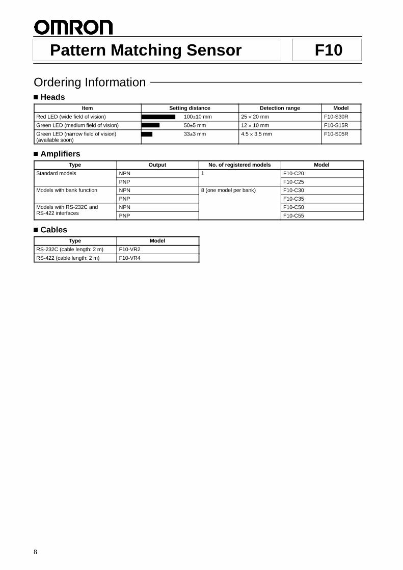
Ordering InformationHeads
Item Setting distance Detection range Model
Red LED (wide field of vision) 100±10 mm 25 × 20 mm F10-S30R
Green LED (medium field of vision) 50±5 mm 12 × 10 mm F10-S15R
Green LED (narrow field of vision)(available soon)
33±3 mm 4.5 × 3.5 mm F10-S05R
AmplifiersType Output No. of registered models Model
Standard models NPN 1 F10-C20Standard models
PNP
1
F10-C25
Models with bank function NPN 8 (one model per bank) F10-C30Models with bank function
PNP
8 (one model per bank)
F10-C35
Models with RS-232C andRS-422 interfaces
NPN F10-C50Models with RS-232C andRS-422 interfaces PNP F10-C55
CablesType Model
RS-232C (cable length: 2 m) F10-VR2
RS-422 (cable length: 2 m) F10-VR4
F10 F10
9
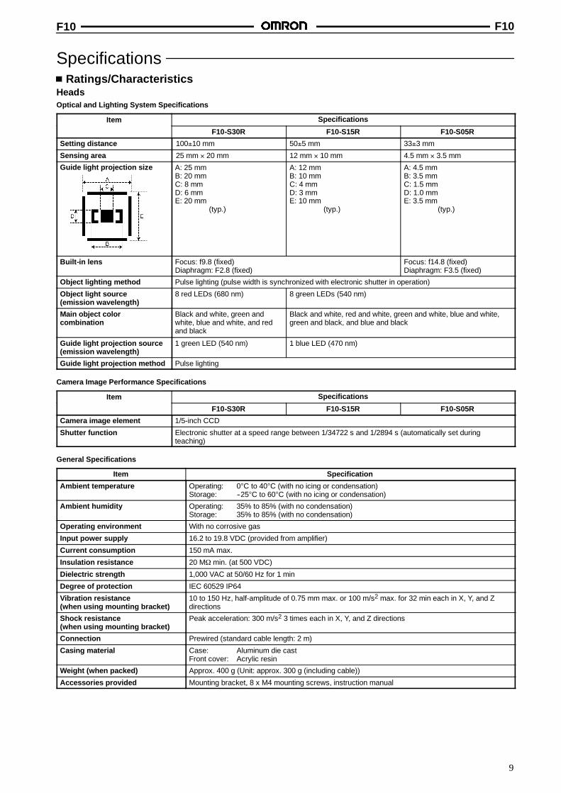
SpecificationsRatings/Characteristics
HeadsOptical and Lighting System Specifications
Item SpecificationsItem
F10-S30R F10-S15R F10-S05R
Setting distance 100±10 mm 50±5 mm 33±3 mm
Sensing area 25 mm × 20 mm 12 mm × 10 mm 4.5 mm × 3.5 mm
Guide light projection size A: 25 mmB: 20 mmC: 8 mmD: 6 mmE: 20 mm
(typ.)
A: 12 mmB: 10 mmC: 4 mmD: 3 mmE: 10 mm
(typ.)
A: 4.5 mmB: 3.5 mmC: 1.5 mmD: 1.0 mmE: 3.5 mm
(typ.)
Built-in lens Focus: f9.8 (fixed)Diaphragm: F2.8 (fixed)
Focus: f14.8 (fixed)Diaphragm: F3.5 (fixed)
Object lighting method Pulse lighting (pulse width is synchronized with electronic shutter in operation)
Object light source(emission wavelength)
8 red LEDs (680 nm) 8 green LEDs (540 nm)
Main object colorcombination
Black and white, green andwhite, blue and white, and redand black
Black and white, red and white, green and white, blue and white,green and black, and blue and black
Guide light projection source(emission wavelength)
1 green LED (540 nm) 1 blue LED (470 nm)
Guide light projection method Pulse lighting
Camera Image Performance Specifications
Item SpecificationsItem
F10-S30R F10-S15R F10-S05R
Camera image element 1/5-inch CCD
Shutter function Electronic shutter at a speed range between 1/34722 s and 1/2894 s (automatically set duringteaching)
General Specifications
Item Specification
Ambient temperature Operating: 0°C to 40°C (with no icing or condensation)Storage: --25°C to 60°C (with no icing or condensation)
Ambient humidity Operating: 35% to 85% (with no condensation)Storage: 35% to 85% (with no condensation)
Operating environment With no corrosive gas
Input power supply 16.2 to 19.8 VDC (provided from amplifier)
Current consumption 150 mA max.
Insulation resistance 20 MΩ min. (at 500 VDC)
Dielectric strength 1,000 VAC at 50/60 Hz for 1 min
Degree of protection IEC 60529 IP64
Vibration resistance(when using mounting bracket)
10 to 150 Hz, half-amplitude of 0.75 mm max. or 100 m/s2 max. for 32 min each in X, Y, and Zdirections
Shock resistance(when using mounting bracket)
Peak acceleration: 300 m/s2 3 times each in X, Y, and Z directions
Connection Prewired (standard cable length: 2 m)
Casing material Case: Aluminum die castFront cover: Acrylic resin
Weight (when packed) Approx. 400 g (Unit: approx. 300 g (including cable))
Accessories provided Mounting bracket, 8 x M4 mounting screws, instruction manual
F10 F10
10
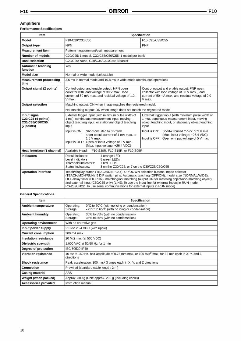
AmplifiersPerformance Specifications
Item Specification
Model F10-C20/C30/C50 F10-C25/C35/C55
Output type NPN PNP
Measurement item Pattern measurement/plain measurement
Number of models C20/C25: 1 model, C30/C35/C50/C55: 1 model per bank
Bank selection C20/C25: None, C30/C35/C50/C55: 8 banks
Automatic teachingfunction
Yes
Model size Normal or wide mode (selectable)
Measurement processingtime
3.6 ms in normal mode and 10.8 ms in wide mode (continuous operation)
Output signal (2 points) Control output and enable output: NPN opencollector with load voltage of 30 V max., loadcurrent of 50 mA max. and residual voltage of 1.2V max.
Control output and enable output: PNP opencollector with load voltage of 30 V max., loadcurrent of 50 mA max. and residual voltage of 2.0V max.
Output selection Matching output: ON when image matches the registered model.
Not matching output: ON when image does not match the registered model.
Input signalC20/C25 (4 points)C30/C35/C50/C55(7 points)
External trigger input (with minimum pulse width of1 ms), continuous measurement input, movingobject teaching input, or stationary object teachinginput
Input is ON: Short-circuited to 0 V withshort-circuit current of 1 mA max. or1.5 V max.
Input is OFF: Open or input voltage of 5 V min.(Max. input voltage: +26.4 VDC)
External trigger input (with minimum pulse width of1 ms), continuous measurement input, movingobject teaching input, or stationary object teachinginput
Input is ON: Short-circuited to Vcc or 9 V min.(Max. input voltage: +26.4 VDC)
Input is OFF: Open or input voltage of 5 V max.
Head interface (1 channel) Available Head: F10-S30R, F10-S15R, or F10-S05R
Indicators Result indicator: 1 orange LEDLevel indicators: 8 green LEDsThreshold indicators: 7 red LEDsStatus indicators: 3 on the C20/C25, or 7 on the C30/C35/C50/C55
Operation interface Teach/display button (TEACH/DISPLAY), UP/DOWN selection buttons, mode selector(TEACH/MON/RUN), 5 DIP switch pins: Automatic teaching (OFF/ON), model size (NORMAL/WIDE),OFF-delay timer (OFF/ON), matching/not matching (output ON for matching object/non-matching object),and external input (C50/C55 only) (LINE: To use the input line for external inputs in RUN mode;RS-232C/422: To use serial communications for external inputs in RUN mode)
General Specifications
Item Specification
Ambient temperature Operating: 0°C to 50°C (with no icing or condensation)Storage: --25°C to 65°C (with no icing or condensation)
Ambient humidity Operating: 35% to 85% (with no condensation)Storage: 35% to 85% (with no condensation)
Operating environment With no corrosive gas
Input power supply 21.6 to 26.4 VDC (with ripple)
Current consumption 300 mA max.
Insulation resistance 20 MΩ min. (at 500 VDC)
Dielectric strength 1,000 VAC at 50/60 Hz for 1 min
Degree of protection IEC 60529 IP40
Vibration resistance 10 Hz to 150 Hz, half-amplitude of 0.75 mm max. or 100 m/s2 max. for 32 min each in X, Y, and Zdirections
Shock resistance Peak acceleration: 300 m/s2 3 times each in X, Y, and Z directions
Connection Prewired (standard cable length: 2 m)
Casing material ABS
Weight (when packed) Approx. 300 g (Unit: approx. 200 g (including cable))
Accessories provided Instruction manual
F10 F10
11
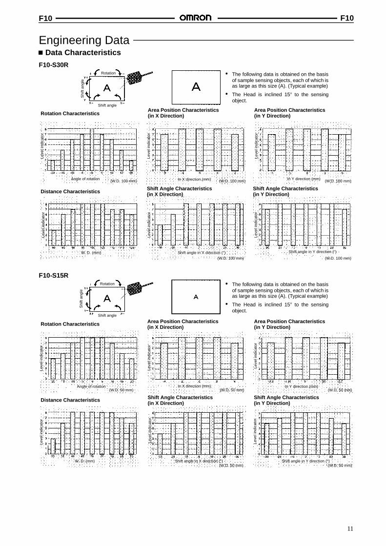
Engineering DataData Characteristics
F10-S30R
Rotation CharacteristicsArea Position Characteristics(in X Direction)
Leve
lind
icat
or
Area Position Characteristics(in Y Direction)
Angle of rotation In X direction (mm) In Y direction (mm)
Leve
lind
icat
or
Leve
lind
icat
or
Distance Characteristics Shift Angle Characteristics(in X Direction)
Leve
lind
icat
or
Shift angle in X direction (°)
Leve
lind
icat
or
Leve
lind
icat
or
Shift Angle Characteristics(in Y Direction)
Shift angle in Y direction (°)
• The following data is obtained on the basisof sample sensing objects, each of which isas large as this size (A). (Typical example)
• The Head is inclined 15° to the sensingobject.
Rotation
Shi
ftan
gle
Shift angle
W. D. (mm)
(W.D. 100 mm) (W.D. 100 mm) (W.D. 100 mm)
(W.D. 100 mm)(W.D. 100 mm)
F10-S15R
Rotation Characteristics Area Position Characteristics(in X Direction)
Leve
lind
icat
or
Area Position Characteristics(in Y Direction)
Angle of rotation In X direction (mm) In Y direction (mm)
Leve
lind
icat
or
Leve
lind
icat
or
Distance Characteristics Shift Angle Characteristics(in X Direction)
Leve
lind
icat
or
Shift angle in X direction (°)
Leve
lind
icat
or
Leve
lind
icat
or
Shift Angle Characteristics(in Y Direction)
Shift angle in Y direction (°)
• The following data is obtained on the basisof sample sensing objects, each of which isas large as this size (A). (Typical example)
• The Head is inclined 15° to the sensingobject.
Rotation
Shi
ftan
gle
Shift angle
W. D. (mm)
(W.D. 50 mm) (W.D. 50 mm) (W.D. 50 mm)
(W.D. 50 mm)(W.D. 50 mm)

F10 F10
12
F10-S05R available soon
F10 F10
13
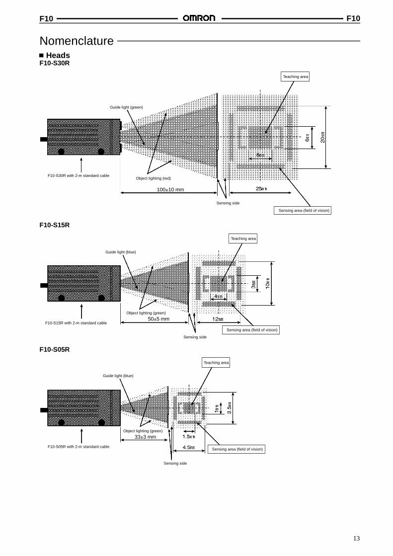
NomenclatureHeads
F10-S30R
Guide light (green)
Object lighting (red)F10-S30R with 2-m standard cable
Sensing side
Teaching area
Sensing area (field of vision)
100±10 mm
F10-S15R
Guide light (blue)
Object lighting (green)
F10-S15R with 2-m standard cable
Sensing side
Teaching area
Sensing area (field of vision)
50±5 mm
F10-S05R
Guide light (blue)
Object lighting (green)
F10-S05R with 2-m standard cable
Sensing side
Teaching area
Sensing area (field of vision)
33±3 mm
F10 F10
14
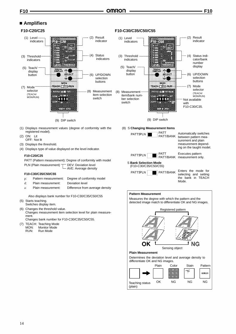
Amplifiers
F10-C20/C25 F10-C30/C35/C50/C55
(1) Levelindicators
(3) Thresholdindicators
(5) Teach/displaybutton
(7) Modeselector(TEACH/MON/RUN)
(2) Resultindicator
(4) Statusindicators
(4) Status indi-cator/banknumberdisplay
(6) UP/DOWNselectionbuttons
(8) Measurementitem selectionswitch
(8) Measurementitem/bank num-ber selectionswitch
(9) DIP switch
Not availablewithF10-C30/C35.
(1) Levelindicators
(3) Thresholdindicators
(5) Teach/displaybutton
(9) DIP switch
(2) Resultindicator
(6) UP/DOWNselectionbuttons
(7) Modeselector(TEACH/MON/RUN)
(1) Displays measurement values (degree of conformity with theregistered model).
(2) ON: LitOFF: Not lit
(3) Displays the threshold.(4) Displays type of value displayed on the level indicator.
F10-C20/C25PATT (Pattern measurement): Degree of conformity with modelPLN (Plain measurement) DEV: Deviation level
AVE: Average density
F10-C30/C35/C50/C55p: Pattern measurement: Degree of conformity modeld: Plain measurement: Deviation levela: Plain measurement: Difference from average density
Also displays bank number for F10-C30/C35/C50/C55(5) Starts teaching.
Switches display item.(6) Changes the threshold value.
Changes measurement item selection level for plain measure-ment.Changes bank number for F10-C30/C35/C50/C55.
(7) TEACH: Teaching ModeMON: Monitor ModeRUN: Run Mode
(8) S Changing Measurement Items
Automatically switchesbetween pattern mea-surement and plainmeasurement depend-ing on the taught model.
Executes patternmeasurement only.
S Bank Selection Mode(F10-C30/C35/C50/C55)
Enters the mode forselecting and settingthe bank in TEACHMode.
PATTSPLN PATTPATT/BANK
PATTSPLN PATTPATT/BANK
PATTSPLN PATT/BANK
Pattern Measurement
Measures the degree with which the pattern and thedetected image match to differentiate OK and NG images.
Registered pattern
Sensing objectPlain Measurement
Determines the deviation level and average density todifferentiate OK and NG images.
Plain
Teaching status(plain)
Color Stain Pattern
OK NG NG NG
F10 F10
15
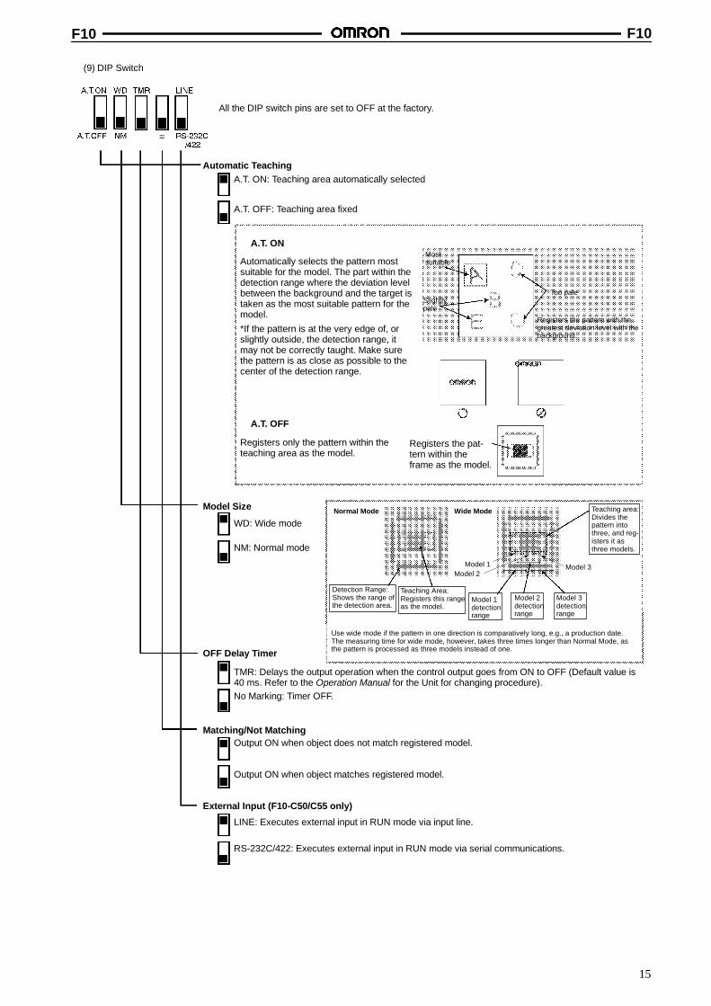
(9) DIP Switch
All the DIP switch pins are set to OFF at the factory.
Automatic TeachingA.T. ON: Teaching area automatically selected
A.T. OFF: Teaching area fixed
Automatically selects the pattern mostsuitable for the model. The part within thedetection range where the deviation levelbetween the background and the target istaken as the most suitable pattern for themodel.
Mostsuitable
Slightlypale
Too pale
Registers the pattern with thegreatest deviation level with thebackground.
*If the pattern is at the very edge of, orslightly outside, the detection range, itmay not be correctly taught. Make surethe pattern is as close as possible to thecenter of the detection range.
Registers only the pattern within theteaching area as the model.
Registers the pat-tern within theframe as the model.
Model Size
WD: Wide mode
NM: Normal mode
Normal Mode
Detection Range:Shows the range ofthe detection area.
Teaching Area:Registers this rangeas the model.
Wide Mode Teaching area:Divides thepattern intothree, and reg-isters it asthree models.
Model 1detectionrange
Model 2detectionrange
Model 3detectionrange
Use wide mode if the pattern in one direction is comparatively long, e.g., a production date.The measuring time for wide mode, however, takes three times longer than Normal Mode, asthe pattern is processed as three models instead of one.OFF Delay Timer
TMR: Delays the output operation when the control output goes from ON to OFF (Default value is40 ms. Refer to the Operation Manual for the Unit for changing procedure).No Marking: Timer OFF.
Matching/Not MatchingOutput ON when object does not match registered model.
Output ON when object matches registered model.
External Input (F10-C50/C55 only)
LINE: Executes external input in RUN mode via input line.
RS-232C/422: Executes external input in RUN mode via serial communications.
A.T. OFF
A.T. ON
=
Model 1Model 2
Model 3
F10 F10
16
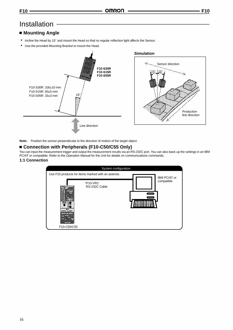
InstallationMounting Angle
• Incline the Head by 15° and mount the Head so that no regular reflection light affects the Sensor.
• Use the provided Mounting Bracket to mount the Head.
F10-S30RF10-S15RF10-S05R
Line direction
15°
15° 15°
Sensor direction
Productionline direction
Simulation
F10-S30R: 100±10 mmF10-S15R: 50±5 mmF10-S05R: 33±3 mm
Note: Position the sensor perpendicular to the direction of motion of the target object.
Connection with Peripherals (F10-C50/C55 Only)You can input the measurement trigger and output the measurement results via an RS-232C port. You can also back up the settings in an IBMPC/AT or compatible. Refer to the Operation Manual for the Unit for details on communications commands.
1:1 Connection
System configuration
*F10-VR2RS-232C Cable
IBM PC/AT orcompatible
F10-C50/C55
Use F10 products for items marked with an asterisk.
F10 F10
17
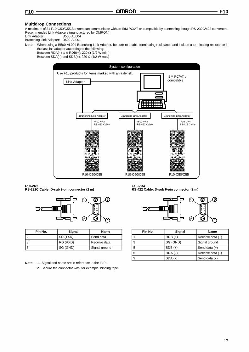
Multidrop ConnectionsA maximum of 31 F10-C50/C55 Sensors can communicate with an IBM PC/AT or compatible by connecting though RS-232C/422 converters.Recommended Link Adapters (manufactured by OMRON)Link Adapter: B500-AL004Branching Link Adapter: B500-AL001Note: When using a B500-AL004 Branching Link Adapter, be sure to enable terminating resistance and include a terminating resistance in
the last link adapter according to the following:Between RDA(--) and RDB(+): 220 Ω (1/2 W min.)Between SDA(--) and SDB(+): 220 Ω (1/2 W min.)
System configuration
Use F10 products for items marked with an asterisk.
Link Adapter
IBM PC/AT orcompatible
Branching Link Adapter Branching Link Adapter Branching Link Adapter
*F10-VR4RS-422 Cable
*F10-VR4RS-422 Cable
*F10-VR4RS-422 Cable
F10-C50/C55 F10-C50/C55 F10-C50/C55
F10-VR2RS-232C Cable: D-sub 9-pin connector (2 m)
Pin No. Signal Name
2 SD (TXD) Send data
3 RD (RXD) Receive data
5 SG (GND) Signal ground
F10-VR4RS-422 Cable: D-sub 9-pin connector (2 m)
Pin No. Signal Name
1 RDB (+) Receive data (+)
3 SG (GND) Signal ground
5 SDB (+) Send data (+)
6 RDA (--) Receive data (--)
9 SDA (--) Send data (--)Note: 1. Signal and name are in reference to the F10.
2. Secure the connector with, for example, binding tape.
F10 F10
18
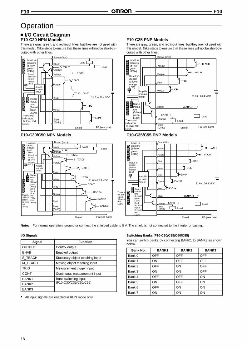
OperationI/O Circuit Diagram
F10-C20 NPN ModelsThere are gray, green, and red input lines, but they are not used withthis model. Take steps to ensure that these lines will not be short-cir-cuited with other lines.
F10-C25 PNP ModelsThere are gray, green, and red input lines, but they are not used withthis model. Take steps to ensure that these lines will not be short-cir-cuited with other lines.
Level in-dicators(8-levelgreenLEDs)Resultindicator(1-levelorangeLED)
Thresholdindicators(7-level red
LEDs)
Shield
Load
Orange
Yellow
Purple
Pink
White
Blue(GND)
Statusindica-tors(3-levelgreenLEDs)
21.6 to 26.4 VDC
Amplifi-er maincircuit
Brown (Vcc)
BlackLoad
FG (see note)
Level in-dicators(8-levelgreenLEDs)
Result in-dicator(1-levelorangeLED)
Amplifi-er maincircuit
Thresholdindicators(7-level red
LEDs) Shield
Brown (Vcc)
Black
Orange
Yellow
Purple
Pink
White
Blue(GND)
Statusindica-tors(3-levelgreenLEDs)
21.6 to 26.4 VDC
Load
FG (see note)
ENABLoad
F10-C30/C50 NPN Models F10-C35/C55 PNP Models
Level indi-cators(8-levelgreenLEDs)
Result in-dicator(1-levelorangeLED)
Amplifi-er maincircuit
Thresh-old indi-cators(7-level
redLEDs)
LoadLoad
Statusindica-tors(3-levelgreenLEDs)
Brown (Vcc)
Black
Orange
Yellow
Purple
Pink
White
Blue(GND)
Gray
Green
Red
Shield FG (see note)
21.6 to 26.4 VDC
BankNo. in-dica-tors(7-lev-el redLEDs)
Level in-dicators(8-levelgreenLEDs)
Result in-dicator(1-levelorangeLED)
Amplifi-er maincircuit
Thresh-old indi-cators(7-level
redLEDs) Load
Load
Brown (Vcc)
Black
Orange
Yellow
Purple
Pink
White
Blue(GND)
Gray
Green
Red
Shield FG (see note)
21.6 to 26.4 VDC
Statusindica-tors(3-levelgreenLEDs)BankNo. indi-cators(7-levelredLEDs)
ENAB
CONT
BANK1
BANK2
BANK3
Note: For normal operation, ground or connect the shielded cable to 0 V. The shield is not connected to the interior or casing.
I/O Signals
Signal Function
OUTPUT Control output
ENAB Enabled output
S_TEACH Stationary object teaching input
M_TEACH Moving object teaching input
TRIG Measurement trigger input
CONT Continuous measurement input
BANK1 Bank switching input(F10-C30/C35/C50/C55)BANK2
Bank switching input(F10-C30/C35/C50/C55)
BANK3
• All input signals are enabled in RUN mode only.
Switching Banks (F10-C30/C35/C50/C55)You can switch banks by connecting BANK1 to BANK3 as shownbelow.
Bank No. BANK1 BANK2 BANK3
Bank 0 OFF OFF OFF
Bank 1 ON OFF OFF
Bank 2 OFF ON OFF
Bank 3 ON ON OFF
Bank 4 OFF OFF ON
Bank 5 ON OFF ON
Bank 6 OFF ON ON
Bank 7 ON ON ON
F10 F10
19
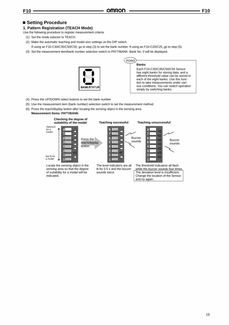
Setting Procedure1. Pattern Registration (TEACH Mode)Use the following procedure to register measurement criteria.
(1) Set the mode selector to TEACH.
(2) Make the automatic teaching and model size settings on the DIP switch.
If using an F10-C30/C35/C50/C55, go to step (3) to set the bank number. If using an F10-C20/C25, go to step (5).
(3) Set the measurement item/bank number selection switch to PATT/BANK. Bank No. 0 will be displayed.
BanksEach F10-C30/C35/C50/C55 Sensorhas eight banks for storing data, and adifferent threshold value can be stored ineach of the eight banks. Use this func-tion to take measurements under vari-ous conditions. You can switch operationsimply by switching banks.
POINT
(4) Press the UP/DOWN select buttons to set the bank number.
(5) Use the measurement item (bank number) selection switch to set the measurement method.
(6) Press the teach/display button after locating the sensing object in the sensing area.Measurement Items: PATT/BANK
Checking the degree ofsuitability of the model Teaching successful Teaching unsuccessful
Optimumfor amodel
Not fit fora model
Locate the sensing object in thesensing area so that the degreeof suitability for a model will beindicated.
The level indicators are alllit for 0.5 s and the buzzersounds twice.
The threshold indicators all flashwhile the buzzer sounds four times.The deviation level is insufficient.Change the location of the Sensorand try again.
Press theteach/displaybutton.
87654321
87654321
87654321
Buzzersounds Buzzer
sounds
F10 F10
20
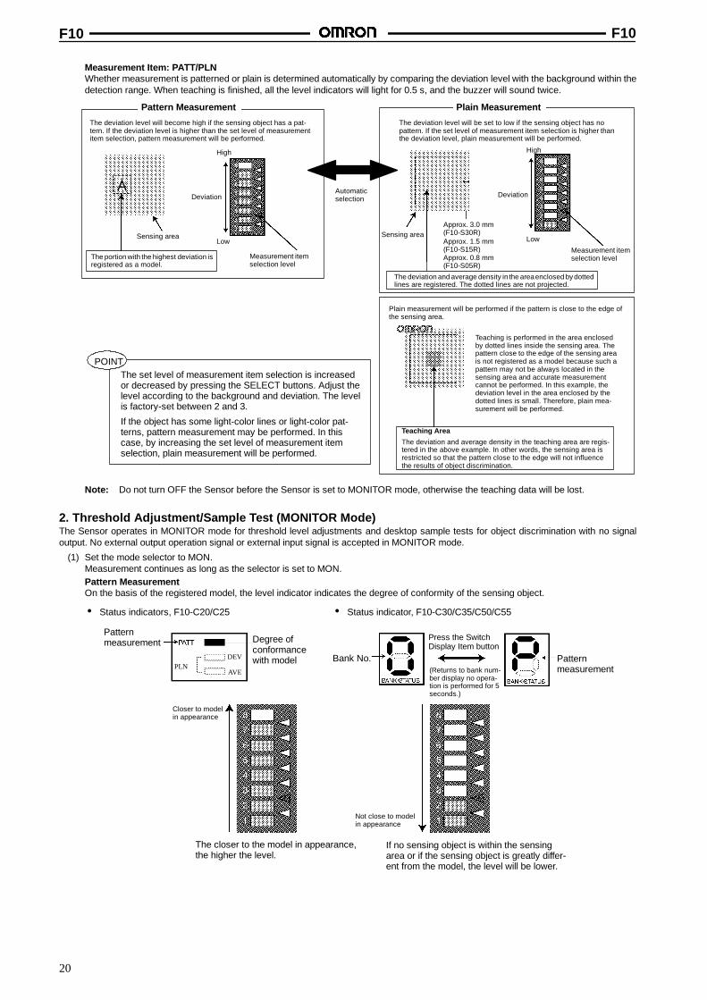
Measurement Item: PATT/PLNWhether measurement is patterned or plain is determined automatically by comparing the deviation level with the background within thedetection range. When teaching is finished, all the level indicators will light for 0.5 s, and the buzzer will sound twice.
Pattern Measurement Plain Measurement
The deviation level will become high if the sensing object has a pat-tern. If the deviation level is higher than the set level of measurementitem selection, pattern measurement will be performed.
The deviation level will be set to low if the sensing object has nopattern. If the set level of measurement item selection is higher thanthe deviation level, plain measurement will be performed.
Plain measurement will be performed if the pattern is close to the edge ofthe sensing area.
Teaching Area
The deviation and average density in the teaching area are regis-tered in the above example. In other words, the sensing area isrestricted so that the pattern close to the edge will not influencethe results of object discrimination.
Teaching is performed in the area enclosedby dotted lines inside the sensing area. Thepattern close to the edge of the sensing areais not registered as a model because such apattern may not be always located in thesensing area and accurate measurementcannot be performed. In this example, thedeviation level in the area enclosed by thedotted lines is small. Therefore, plain mea-surement will be performed.
The set level of measurement item selection is increasedor decreased by pressing the SELECT buttons. Adjust thelevel according to the background and deviation. The levelis factory-set between 2 and 3.
If the object has some light-color lines or light-color pat-terns, pattern measurement may be performed. In thiscase, by increasing the set level of measurement itemselection, plain measurement will be performed.
Sensing area
The portion with the highest deviation isregistered as a model.
High
Deviation
Low
Measurement itemselection level
Automaticselection
Sensing area
The deviation and average density in the areaenclosed by dottedlines are registered. The dotted lines are not projected.
High
Deviation
Low
Measurement itemselection levelApprox. 0.8 mm
(F10-S05R)
Approx. 1.5 mm(F10-S15R)
Approx. 3.0 mm(F10-S30R)
8
7
6
5
4
3
2
1
A
8
7
6
5
4
3
2
1
POINT
Note: Do not turn OFF the Sensor before the Sensor is set to MONITOR mode, otherwise the teaching data will be lost.
2. Threshold Adjustment/Sample Test (MONITOR Mode)The Sensor operates in MONITOR mode for threshold level adjustments and desktop sample tests for object discrimination with no signaloutput. No external output operation signal or external input signal is accepted in MONITOR mode.
(1) Set the mode selector to MON.Measurement continues as long as the selector is set to MON.Pattern MeasurementOn the basis of the registered model, the level indicator indicates the degree of conformity of the sensing object.
Closer to modelin appearance
The closer to the model in appearance,the higher the level.
If no sensing object is within the sensingarea or if the sensing object is greatly differ-ent from the model, the level will be lower.
• Status indicators, F10-C20/C25 • Status indicator, F10-C30/C35/C50/C55
Patternmeasurement Degree of
conformancewith model Bank No.
Press the SwitchDisplay Item button
(Returns to bank num-ber display no opera-tion is performed for 5seconds.)
Not close to modelin appearance
PatternmeasurementPLN
DEV
AVE
F10 F10
21
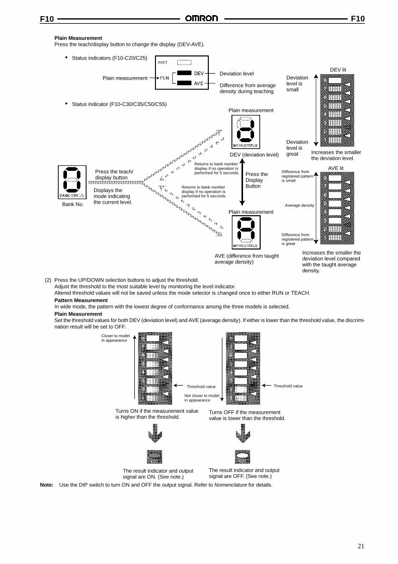
Plain MeasurementPress the teach/display button to change the display (DEV-AVE).
• Status indicators (F10-C20/C25)
Plain measurementDeviation level
Difference from averagedensity during teaching
• Status indicator (F10-C30/C35/C50/C55)
Bank No.
Press the teach/display button
Displays themode indicatingthe current level.
Returns to bank numberdisplay if no operation isperformed for 5 seconds.
Returns to bank numberdisplay if no operation isperformed for 5 seconds.
Plain measurement
DEV (deviation level)
Press theDisplayButton
Plain measurement
AVE (difference from taughtaverage density)
Deviationlevel issmall
Deviationlevel isgreat Increases the smaller
the deviation level.
DEV lit
AVE litDifference fromregistered patternis small
Average density
Difference fromregistered patternis great
Increases the smaller thedeviation level comparedwith the taught averagedensity.
PATT
(2) Press the UP/DOWN selection buttons to adjust the threshold.Adjust the threshold to the most suitable level by monitoring the level indicator.Altered threshold values will not be saved unless the mode selector is changed once to either RUN or TEACH.Pattern MeasurementIn wide mode, the pattern with the lowest degree of conformance among the three models is selected.Plain MeasurementSet the threshold values for both DEV (deviation level) and AVE (average density). If either is lower than the threshold value, the discrimi-nation result will be set to OFF.
Closer to modelin appearance
Turns ON if the measurement valueis higher than the threshold.
Not closer to modelin appearance
Turns OFF if the measurementvalue is lower than the threshold.
Threshold value Threshold value
The result indicator and outputsignal are ON. (See note.)
The result indicator and outputsignal are OFF. (See note.)
Note: Use the DIP switch to turn ON and OFF the output signal. Refer to Nomenclature for details.
F10 F10
22
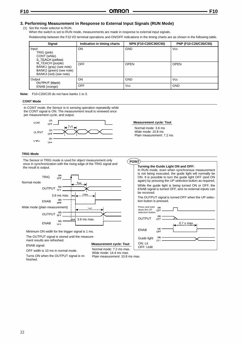
3. Performing Measurement in Response to External Input Signals (RUN Mode)(1) Set the mode selector to RUN.
When the switch is set to RUN mode, measurements are made in response to external input signals.
Relationship between the F10 I/O terminal operations and ON/OFF indications in the timing charts are as shown in the following table.
Signal Indication in timing charts NPN (F10-C20/C30/C50) PNP (F10-C25/C35/C55)
InputTRIG (pink)CONT (white)S_TEACH (yellow)M_TEACH (purple)
ON GND Vcc
S_TEACH (yellow)M_TEACH (purple)BANK1 (gray) (see note)BANK2 (green) (see note)BANK3 (red) (see note)
OFF OPEN OPEN
OutputOUTPUT (black)
ON GND VccOUTPUT (black)ENAB (orange) OFF Vcc GND
Note: F10-C20/C25 do not have banks 1 to 3.
CONT Mode
In CONT mode, the Sensor is in sensing operation repeatedly whilethe CONT signal is ON. The measurement result is renewed onceper measurement cycle, and output.
Measurement cycle: Tout
Normal mode: 7.2 ms max.Wide mode: 14.4 ms max.Plain measurement: 10.8 ms max.
TRIG Mode
The Sensor in TRIG mode is used for object measurement onlyonce in synchronization with the rising edge of the TRIG signal andthe result is output.
Measurement cycle: Tout
Normal mode: 3.6 msWide mode: 10.8 msPlain measurement: 7.2 ms
Turning the Guide Light ON and OFF:In RUN mode, even when synchronous measurementis not being executed, the guide light will normally beON. It is possible to turn the guide light OFF (and ONagain) by pressing the UP selection button as required.While the guide light is being turned ON or OFF, theENAB signal is turned OFF, and no external inputs canbe received.The OUTPUT signal is turned OFF when the UP selec-tion button is pressed.
Press and holddown the UPselection button.
0.7 s max.
Guide light
ON: LitOFF: Unlit
Normal mode
3.6 ms max.
Wide mode (plain measurement)
3.6 ms max.
Minimum ON width for the trigger signal is 1 ms.
The OUTPUT signal is stored until the measure-ment results are refreshed.
ENAB signal:
OFF width is 10 ms in normal mode.
Turns ON when the OUTPUT signal is re-freshed.
TRIG
OUTPUT
ENAB
OUTPUT
ENABOUTPUT
ENAB
POINT
F10 F10
23
External Teaching in RUN ModeIn RUN mode, a model can be registered by external signal input using either of the following methods.
Note: The data of the model is stored in the EEPROM when the teaching process of the Sensor completes. Therefore, do not turn OFF theSensor during the teaching process.If the Sensor is turned OFF, an EEPROM data error will result when the Sensor is turned ON again. In this case, perform properteaching and threshold level adjustments again.
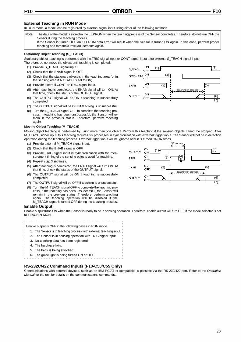
Stationary Object Teaching (S_TEACH)Stationary object teaching is performed with the TRIG signal input or CONT signal input after external S_TEACH signal input.Therefore, do not move the object until teaching is completed.
(1) Provide S_TEACH signal input.(2) Check that the ENAB signal is OFF.(3) Check that the stationary object is in the teaching area (or in
the sensing area if A.TEACH is set to ON).(4) Provide external CONT or TRIG signal input.(5) After teaching is completed, the ENAB signal will turn ON. At
that time, check the status of the OUTPUT signal.(6) The OUTPUT signal will be ON if teaching is successfully
completed.(7) The OUTPUT signal will be OFF if teaching is unsuccessful.(8) Turn the S_TEACH signal OFF to complete the teaching pro-
cess. If teaching has been unsuccessful, the Sensor will re-main in the previous status. Therefore, perform teachingagain.
Teaching in process
S_TEACH (1)
(2)
(4)
(5)
(6)(7)
(8)
Moving Object Teaching (M_TEACH)Moving object teaching is performed by using more than one object. Perform this teaching if the sensing objects cannot be stopped. AfterM_TEACH signal input, this teaching requires six processes in synchronization with external trigger input. The Sensor will not be in detectionoperation during the teaching process. External trigger input will be ignored after it is turned ON six times.
(1) Provide external M_TEACH signal input.(2) Check that the ENAB signal is OFF.(3) Provide TRIG signal input in synchronization with the mea-
surement timing of the sensing objects used for teaching.(4) Repeat step 3 six times.(5) After teaching is completed, the ENAB signal will turn ON. At
that time, check the status of the OUTPUT signal.(6) The OUTPUT signal will be ON if teaching is successfully
completed.(7) The OUTPUT signal will be OFF if teaching is unsuccessful.(8) Turn the M_TEACH signal OFF to complete the teaching pro-
cess. If the teaching has been unsuccessful, the Sensor willremain in the previous status. Therefore, perform teachingagain. The teaching operation will be disabled if theM_TEACH signal is turned OFF during the teaching process.
Teaching in process
M_TEACH
50 ms min.
(1)
(2)
(4)
(5)
(6)(7)
(8)
(3)
Enable OutputEnable output turns ON when the Sensor is ready to be in sensing operation. Therefore, enable output will turn OFF if the mode selector is setto TEACH or MON.
Enable output is OFF in the following cases in RUN mode.
1. The Sensor is in teaching process with external teaching input.2. The Sensor is in sensing operation with TRIG signal input.3. No teaching data has been registered.4. The hardware fails.5. The bank is being switched.6. The guide light is being turned ON or OFF.
RS-232C/422 Command Inputs (F10-C50/C55 Only)Communications with external devices, such as an IBM PC/AT or compatible, is possible via the RS-232/422 port. Refer to the OperationManual for the unit for details on the communications commands.
F10 F10
24
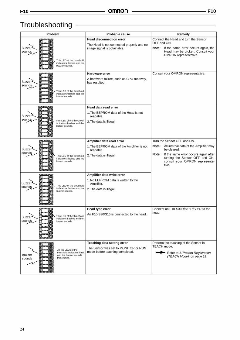
TroubleshootingProblem Probable cause Remedy
This LED of the thresholdindicators flashes and thebuzzer sounds.
8
76
543
21
Buzzersounds
Head disconnection error
The Head is not connected properly and noimage signal is obtainable.
Connect the Head and turn the SensorOFF and ON.
Note: If the same error occurs again, theHead may be broken. Consult yourOMRON representative.
This LED of the thresholdindicators flashes and thebuzzer sounds.
8
76
543
21
Buzzersounds
Hardware error
A hardware failure, such as CPU runaway,has resulted.
Consult your OMRON representative.
This LED of the thresholdindicators flashes and thebuzzer sounds.
8
76
543
21
Buzzersounds
Head data read error
1.The EEPROM data of the Head is notreadable.
2.The data is illegal.
This LED of the thresholdindicators flashes and thebuzzer sounds.
8
76
543
21
Buzzersounds
Amplifier data read error
1.The EEPROM data of the Amplifier is notreadable.
2.The data is illegal.
Turn the Sensor OFF and ON.
Note: All internal data of the Amplifier maybe cleared.
Note: If the same error occurs again afterturning the Sensor OFF and ON,consult your OMRON representa-tive.
This LED of the thresholdindicators flashes and thebuzzer sounds.
8
76
543
21
Buzzersounds
Amplifier data write error
1.No EEPROM data is written to theAmplifier.
2.The data is illegal.
This LED of the thresholdindicators flashes and thebuzzer sounds.
8
76
543
21
Buzzersounds
Head type error
An F10-S30/S15 is connected to the head.
Connect an F10-S30R/S15R/S05R to thehead.
All the LEDs of thethreshold indicators flashand the buzzer soundsthree times.
8
76
543
21
Buzzersounds
Teaching data setting error
The Sensor was set to MONITOR or RUNmode before teaching completed.
Perform the teaching of the Sensor inTEACH mode.
Refer to 1. Pattern Registration(TEACH Mode) on page 19.
F10 F10
25
Problem RemedyProbable cause
This LED of the thresholdindicators flashes and thebuzzer sounds threetimes.
8
76
543
21
Buzzersounds
Serial buffer overflow error
Either the send buffer or receive buffer hasbecome full during communications.
Send buffer overflow
Change the communications settings.
Receive buffer overflow
Wait for a response from the F10, thensend the command.
Control output (OUTPUT) and enableoutput are OFF, and will not turn ON.
A current exceeding the rated value hasflowed to the output transistor and theovercurrent protective circuit has beentriggered.
Reduce the current so that it will notexceed the rated value.
Note: If the output does not turn ON evenafter reducing the current below the ratedvalue, contact your OMRONrepresentative.
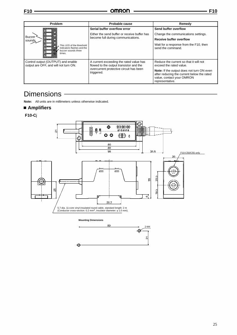
DimensionsNote: All units are in millimeters unless otherwise indicated.
Amplifiers
F10-Cj
Mounting Dimensions
2-M4
F10-C50/C55 only
5.7-dia. 11-core vinyl-insulated round cable, standard length: 2 m(Conductor cross-section: 0.2 mm2, insulator diameter: φ 1.0 mm).
F10 F10
26
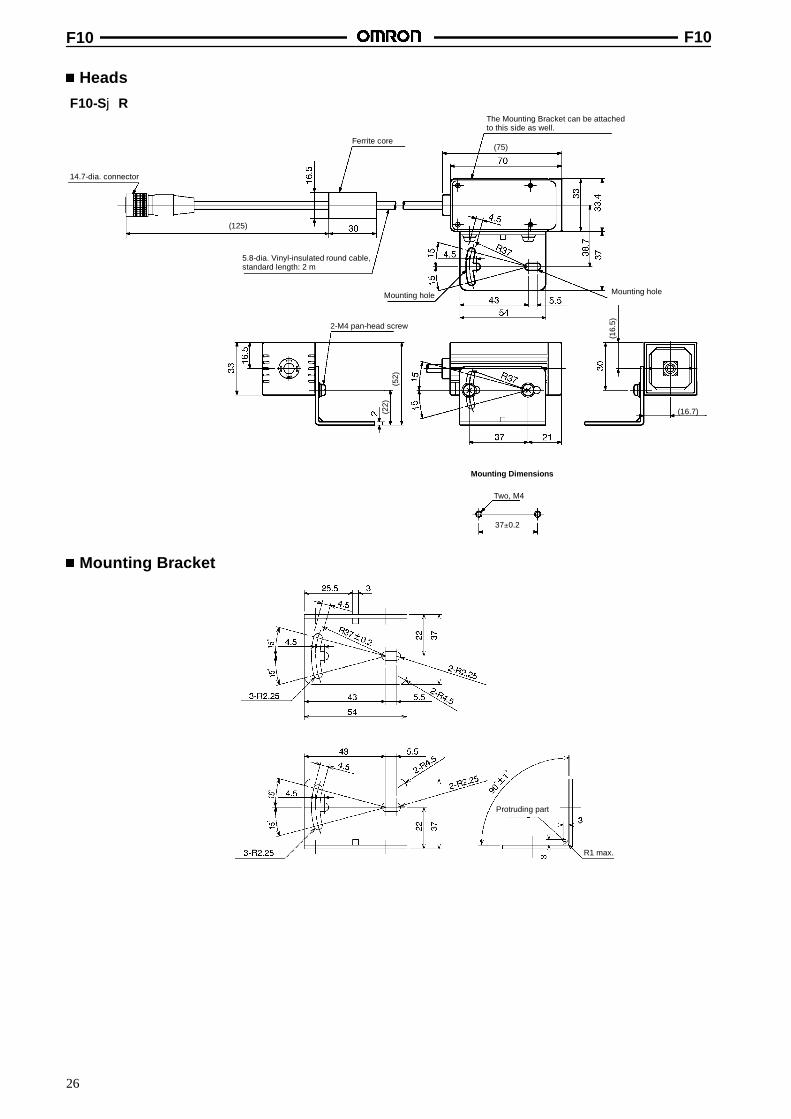
Heads
F10-SjR
Ferrite core
14.7-dia. connector
2-M4 pan-head screw
The Mounting Bracket can be attachedto this side as well.
Mounting hole Mounting hole
Two, M4
Mounting Dimensions
5.8-dia. Vinyl-insulated round cable,standard length: 2 m
37±0.2
(22)
(52)
(16.
5)
(16.7)
(75)
(125)
Mounting Bracket
Protruding part
R1 max.
F10 F10
27
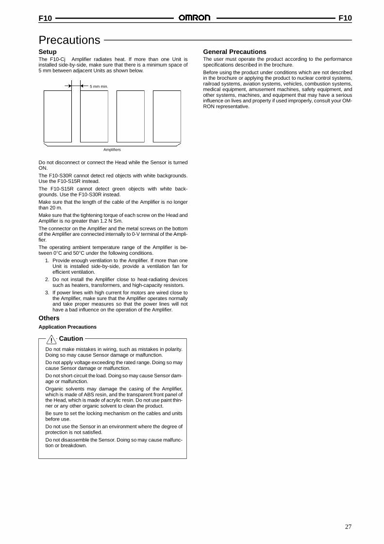
PrecautionsSetupThe F10-Cj Amplifier radiates heat. If more than one Unit isinstalled side-by-side, make sure that there is a minimum space of5 mm between adjacent Units as shown below.
5 mm min.
Amplifiers
Do not disconnect or connect the Head while the Sensor is turnedON.The F10-S30R cannot detect red objects with white backgrounds.Use the F10-S15R instead.The F10-S15R cannot detect green objects with white back-grounds. Use the F10-S30R instead.Make sure that the length of the cable of the Amplifier is no longerthan 20 m.Make sure that the tightening torque of each screw on the Head andAmplifier is no greater than 1.2 N S m.The connector on the Amplifier and the metal screws on the bottomof the Amplifier are connected internally to 0-V terminal of the Ampli-fier.The operating ambient temperature range of the Amplifier is be-tween 0°C and 50°C under the following conditions.
1. Provide enough ventilation to the Amplifier. If more than oneUnit is installed side-by-side, provide a ventilation fan forefficient ventilation.
2. Do not install the Amplifier close to heat-radiating devicessuch as heaters, transformers, and high-capacity resistors.
3. If power lines with high current for motors are wired close tothe Amplifier, make sure that the Amplifier operates normallyand take proper measures so that the power lines will nothave a bad influence on the operation of the Amplifier.
OthersApplication Precautions
Caution
Do not make mistakes in wiring, such as mistakes in polarity.Doing so may cause Sensor damage or malfunction.Do not apply voltage exceeding the rated range. Doing so maycause Sensor damage or malfunction.Do not short-circuit the load. Doing so may cause Sensor dam-age or malfunction.Organic solvents may damage the casing of the Amplifier,which is made of ABS resin, and the transparent front panel ofthe Head, which is made of acrylic resin. Do not use paint thin-ner or any other organic solvent to clean the product.Be sure to set the locking mechanism on the cables and unitsbefore use.Do not use the Sensor in an environment where the degree ofprotection is not satisfied.Do not disassemble the Sensor. Doing so may cause malfunc-tion or breakdown.
General PrecautionsThe user must operate the product according to the performancespecifications described in the brochure.Before using the product under conditions which are not describedin the brochure or applying the product to nuclear control systems,railroad systems, aviation systems, vehicles, combustion systems,medical equipment, amusement machines, safety equipment, andother systems, machines, and equipment that may have a seriousinfluence on lives and property if used improperly, consult your OM-RON representative.
!
F10 F10
28
OMRON CorporationIndustrial Automation Company
Advanced Sensors DivisionSensing Devices and Components Division H.Q.28th Fl., Crystal Tower Bldg.,1-2-27, Shiromi, Chuo-ku,Osaka 540-6028 JapanTel: (81)6-6949-6105/Fax: (81)6-6949-6149
Regional Headquarters
OMRON EUROPE B.V.Wegalaan 67-69, NL-2132 JD HoofddorpThe NetherlandsTel: (31)2356-81-300/Fax: (31)2356-81-388
OMRON ELECTRONICS, INC.1 East Commerce Drive, Schaumburg, IL 60173U.S.A.Tel: (1)847-843-7900/Fax: (1)847-843-8568
OMRON ASIA PACIFIC PTE. LTD.83 Clemenceau Avenue,#11-01, UE Square,Singapore 239920Tel: (65)835-3011/Fax: (65)835-2711
OMRON (CHINA) CO. LTD.21F, Beijing East Ocean CenterNo. 24A Jian Guo Men Wai Da JieChao Yang District, Beijing, 100022ChinaTel: (86)10-6515-5778/Fax: (86)10-6515-5810
ALL DIMENSIONS SHOWN ARE IN MILLIMETERS.To convert millimeters into inches, multiply by 0.03937. To convert grams into ounces, multiply by 0.03527.
In the interest of product improvement, specifications are subject to change without notice.
Printed in Japan0100-10M (0100)
The product has been produced at OMRON Ayabe which obtained ISO9001-approval for its quality systemand ISO14001-approval for its environmental management system from international certification bodies.
Cat. No. Q120-E1-1
Authorized Distributor: