part iii applications of mu-sspw mu mixing elements mu-sspw part3.pdf · part iii applications of...
TRANSCRIPT
1
Part III
Applications of MU-SSPW MU Mixing Elements
Hisao Kojima,* MU Company Ltd.
The 21st century has been dubbed the century of the environment, and it was to help meet the growing need for environmental solutions that the “MU-SSPW” (MU-Static Spiral Perforated Wings) MU Mixing Element was developed. This element consists of multiple clockwise and counterclockwise twisted perforated blades with openings in the center, and papers on wet flue gas and wastewater treatment systems that incorporate MU Mixing Elements have been previously published.1
The original inspiration for this technology is explained in an advertisement in Nature2 and in “The Mayan Ruins and the Path to Technological Innovation.”3 (MU-SSPWs are components of the MU Mixing Element, and the MU Mixer consists of a stack of alternately arranged clockwise and counterclockwise twisting MU Mixing Elements. These are marketed under various names according to their specific form and application, including the “MU Scrubber,” “MU Reactor,” “MU Green Reactor,” “MU Aerator,” and “MU Eductor.”)
In this final part of our three-part series, we describe some examples of applications of the MU Mixing Element that have not previously been unpublished.
* President & CEO
2
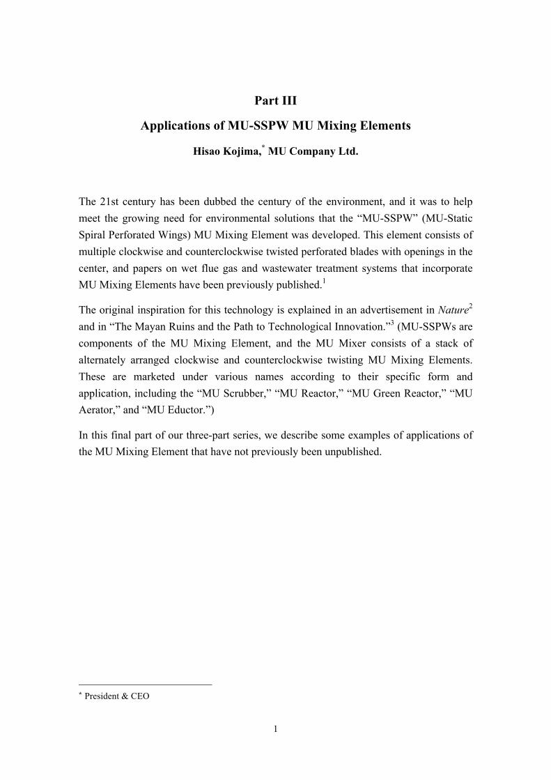
Figure 1 Exterior of MR-40 Radon Stripper
“MU Reactor” radon stripper
The MR-40 Radon Stripper (Figure 1) is a modified second prototype used for the “Super-Kamiokande” (SK) neutrino observation system operated by the University of Tokyo’s Institute for Cosmic Ray Research in Kamioka Mine located in Kamioka-cho, Hida City, Gifu Prefecture, central Japan. Radon is stripped from the ultrapure water in the SK system’s tank by pure (radon-free) air and used to continuously measure the concentration of radon. In order to reduce background from the MU Reactor, its inner and outer surfaces are electro-polished to a surface roughness of not more than Ra 0.4 µm.
The MU Reactor contains a “MU Mixer” high-performance static fluid mixer. Ultrapure water in the SK system tank is supplied to the top of the reactor and pure air is supplied to the bottom in order to effect gas-liquid mixing in the MU Mixer. Radon in the ultrapure water is desorbed as radon gas, which is then fed to a radon measuring device. The high level of efficiency with which gas-liquid mixing and contact occurs allows the ultra-low concentrations (0.1-1.0 mBq/m3) of radon present in ultrapure water to be desorbed at virtually vapor-liquid equilibrium.4
A MU Reactor is being used in a vacuum degasifier for removing radon and krypton from the pure oil used by a liquid scintillator in the KamLAND system for measuring neutrinos.5 The purpose of the degasifier is to purify pure oil in the system by removing radioactive noble gases such as radon and krypton present in the oil in order to lower
3
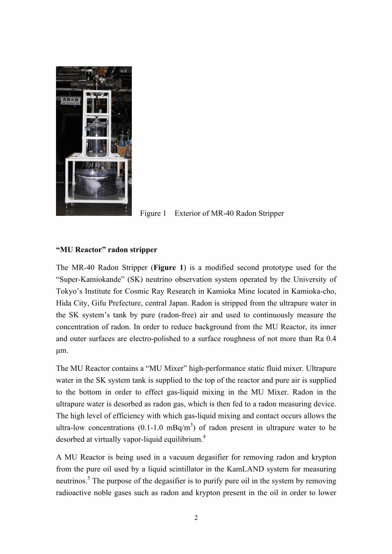
background and raise detection sensitivity6 (Figure 2). It has a desorption efficiency of 99% for radon and 99.9% for krypton.
A MU Reactor is also being used to enable continuous measurement of radon flux between the atmosphere and the ocean aboard The Mirai oceanographic research vessel,7 and it has played a particularly valuable role in enabling continuous measurement in the rough seas of the Antarctic Ocean. This is because the radon stripper’s spiral 180°-twisted perforated blades ensure complete gas-liquid mixing with no gas short-passing even at a 30° incline, so desorption performance is unimpeded.
MU Reactors have one-sixth the diameter, one-fiftieth the volume (gas-liquid contact part), and three-hundredth the gas-liquid contact time of conventional packed tower systems (Figure 3).
The above products were supplied with the cooperation of the Institute for Cosmic Ray Research of the University of Tokyo, the Research Center for Neutrino Science of Tohoku University, Nagoya University, and Gifu University.
Figure 2 KamLAND vacuum degasifier Figure 3 MU Reactor and packed tower system configurations compared
MU Reactor brine vacuum degasifier
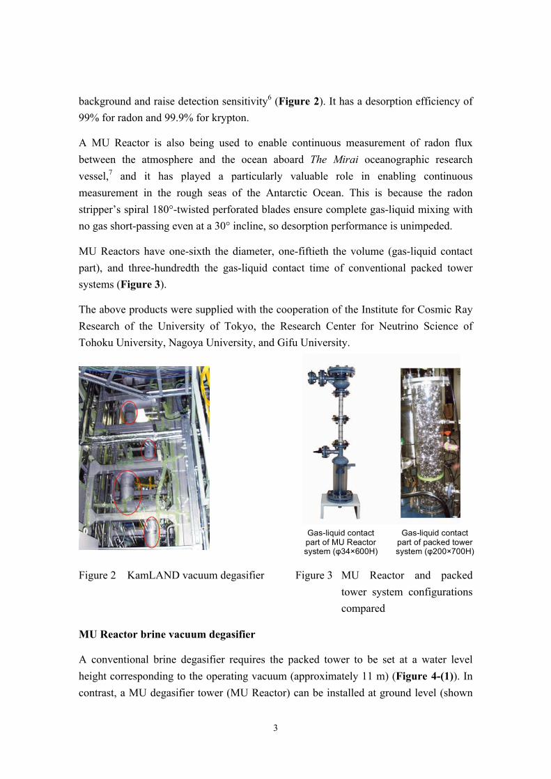
A conventional brine degasifier requires the packed tower to be set at a water level height corresponding to the operating vacuum (approximately 11 m) (Figure 4-(1)). In contrast, a MU degasifier tower (MU Reactor) can be installed at ground level (shown
Gas-liquid contact part of MU Reactor system (φ34×600H)
Gas-liquid contact part of packed tower system (φ200×700H)
4
in Figure 4-(2)).
Brine throughput is 200-250 m3/h. The performance of this MU Reactor is shown in Table 1, and the design specifications of a packed tower system and a MU system are shown in Table 2.
This MU degasifier, which was installed jointly with Mitsubishi Chemical Engineering Corp. and has been in continuous, maintenance-free operation for eight years,
(1) has a tower made of FRP and a MU Mixing element made of PP;
(2) and requires no corrosion-resistant metal as its FRP construction is sufficient to maintain performance even under a vacuum of 25 Torr or less.
Figure 4 MU Reactor vacuum degasifier
Table 1 MU Reactor performance
Raw water Treated water
O2 concentration 8 ppm O2 concentration Max. 1 ppm
CO2 concentration 150 ppm CO2 concentration Max. 15 ppm
NaCl concentration 20 wt% ― ―
(1)
(2)
(1) Conventional degasifier (2) MU degasifier
5
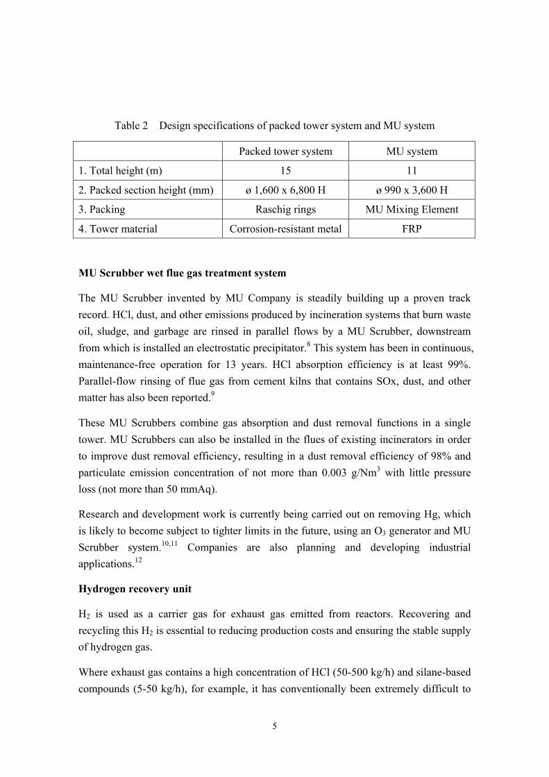
Table 2 Design specifications of packed tower system and MU system
Packed tower system MU system
1. Total height (m) 15 11
2. Packed section height (mm) ø 1,600 x 6,800 H ø 990 x 3,600 H
3. Packing Raschig rings MU Mixing Element
4. Tower material Corrosion-resistant metal FRP
MU Scrubber wet flue gas treatment system
The MU Scrubber invented by MU Company is steadily building up a proven track record. HCl, dust, and other emissions produced by incineration systems that burn waste oil, sludge, and garbage are rinsed in parallel flows by a MU Scrubber, downstream from which is installed an electrostatic precipitator.8 This system has been in continuous, maintenance-free operation for 13 years. HCl absorption efficiency is at least 99%. Parallel-flow rinsing of flue gas from cement kilns that contains SOx, dust, and other matter has also been reported.9
These MU Scrubbers combine gas absorption and dust removal functions in a single tower. MU Scrubbers can also be installed in the flues of existing incinerators in order to improve dust removal efficiency, resulting in a dust removal efficiency of 98% and particulate emission concentration of not more than 0.003 g/Nm3 with little pressure loss (not more than 50 mmAq).
Research and development work is currently being carried out on removing Hg, which is likely to become subject to tighter limits in the future, using an O3 generator and MU Scrubber system.10,11 Companies are also planning and developing industrial applications.12
Hydrogen recovery unit
H2 is used as a carrier gas for exhaust gas emitted from reactors. Recovering and recycling this H2 is essential to reducing production costs and ensuring the stable supply of hydrogen gas.
Where exhaust gas contains a high concentration of HCl (50-500 kg/h) and silane-based compounds (5-50 kg/h), for example, it has conventionally been extremely difficult to
6
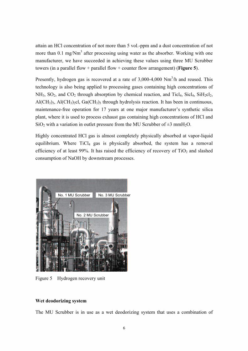
attain an HCl concentration of not more than 5 vol.-ppm and a dust concentration of not more than 0.1 mg/Nm3 after processing using water as the absorber. Working with one manufacturer, we have succeeded in achieving these values using three MU Scrubber towers (in a parallel flow + parallel flow + counter flow arrangement) (Figure 5).
Presently, hydrogen gas is recovered at a rate of 3,000-4,000 Nm3/h and reused. This technology is also being applied to processing gases containing high concentrations of NH3, SO2, and CO2 through absorption by chemical reaction, and Ticl4, Sicl4, SiH2cl2, Al(CH3)3, Al(CH3)2cl, Ga(CH3)3 through hydrolysis reaction. It has been in continuous, maintenance-free operation for 17 years at one major manufacturer’s synthetic silica plant, where it is used to process exhaust gas containing high concentrations of HCl and SiO2 with a variation in outlet pressure from the MU Scrubber of ±3 mmH2O.
Highly concentrated HCl gas is almost completely physically absorbed at vapor-liquid equilibrium. Where TiCl4 gas is physically absorbed, the system has a removal efficiency of at least 99%. It has raised the efficiency of recovery of TiO2 and slashed consumption of NaOH by downstream processes.
Figure 5 Hydrogen recovery unit
Wet deodorizing system
The MU Scrubber is in use as a wet deodorizing system that uses a combination of
No. 3 MU Scrubber
No. 2 MU Scrubber
No. 1 MU Scrubber
7
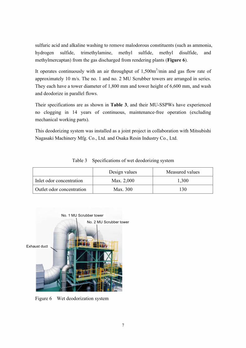
sulfuric acid and alkaline washing to remove malodorous constituents (such as ammonia, hydrogen sulfide, trimethylamine, methyl sulfide, methyl disulfide, and methylmercaptan) from the gas discharged from rendering plants (Figure 6).
It operates continuously with an air throughput of 1,500m3/min and gas flow rate of approximately 10 m/s. The no. 1 and no. 2 MU Scrubber towers are arranged in series. They each have a tower diameter of 1,800 mm and tower height of 6,600 mm, and wash and deodorize in parallel flows.
Their specifications are as shown in Table 3, and their MU-SSPWs have experienced no clogging in 14 years of continuous, maintenance-free operation (excluding mechanical working parts).
This deodorizing system was installed as a joint project in collaboration with Mitsubishi Nagasaki Machinery Mfg. Co., Ltd. and Osaka Resin Industry Co., Ltd.
Table 3 Specifications of wet deodorizing system
Design values Measured values
Inlet odor concentration Max. 2,000 1,300
Outlet odor concentration Max. 300 130
Figure 6 Wet deodorization system
No. 2 MU Scrubber tower
No. 1 MU Scrubber tower
Exhaust duct
8
Use of MU Eductor in large-capacity reaction tank
A MU Eductor® with built-in MU-SSPW is being used in one of the world’s largest reaction tanks (4,000 m3) by a leading Taiwanese chemical manufacturer for organically reacting C5-C10 hydrocarbons.
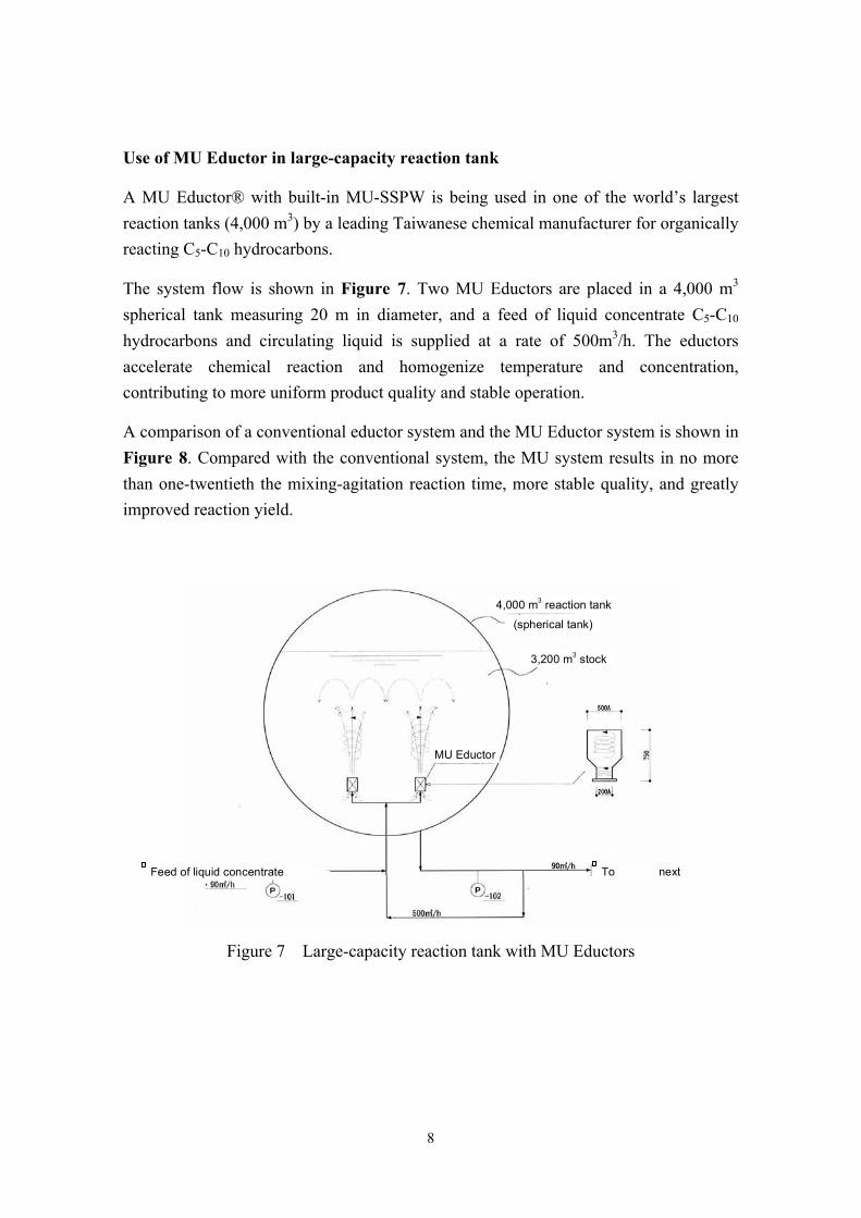
The system flow is shown in Figure 7. Two MU Eductors are placed in a 4,000 m3 spherical tank measuring 20 m in diameter, and a feed of liquid concentrate C5-C10 hydrocarbons and circulating liquid is supplied at a rate of 500m3/h. The eductors accelerate chemical reaction and homogenize temperature and concentration, contributing to more uniform product quality and stable operation.
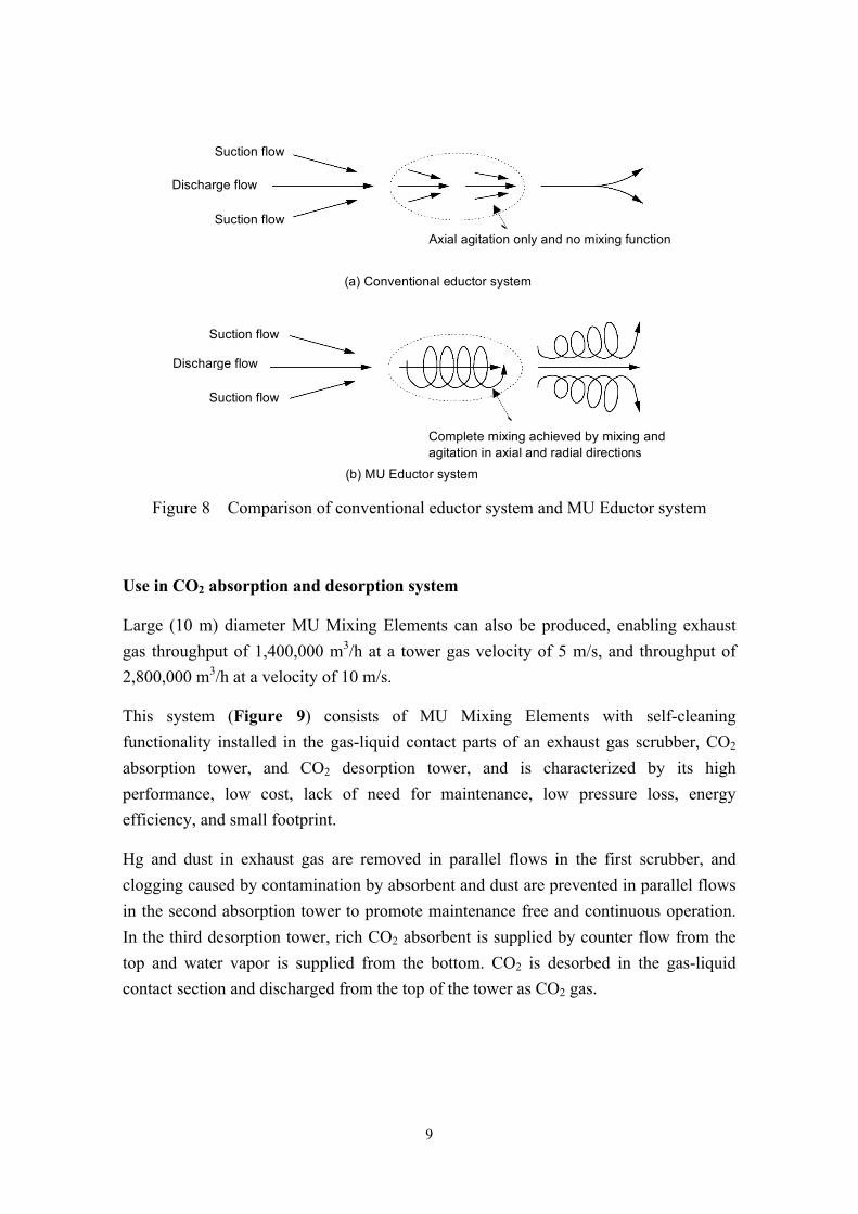
A comparison of a conventional eductor system and the MU Eductor system is shown in Figure 8. Compared with the conventional system, the MU system results in no more than one-twentieth the mixing-agitation reaction time, more stable quality, and greatly improved reaction yield.
Figure 7 Large-capacity reaction tank with MU Eductors
To next process
MU Eductor
3,200 m3 stock
4,000 m3 reaction tank
Feed of liquid concentrate
(spherical tank)
9
Figure 8 Comparison of conventional eductor system and MU Eductor system
Use in CO2 absorption and desorption system
Large (10 m) diameter MU Mixing Elements can also be produced, enabling exhaust gas throughput of 1,400,000 m3/h at a tower gas velocity of 5 m/s, and throughput of 2,800,000 m3/h at a velocity of 10 m/s.
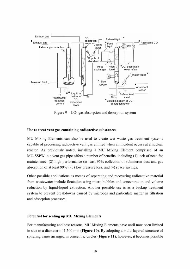
This system (Figure 9) consists of MU Mixing Elements with self-cleaning functionality installed in the gas-liquid contact parts of an exhaust gas scrubber, CO2 absorption tower, and CO2 desorption tower, and is characterized by its high performance, low cost, lack of need for maintenance, low pressure loss, energy efficiency, and small footprint.
Hg and dust in exhaust gas are removed in parallel flows in the first scrubber, and clogging caused by contamination by absorbent and dust are prevented in parallel flows in the second absorption tower to promote maintenance free and continuous operation. In the third desorption tower, rich CO2 absorbent is supplied by counter flow from the top and water vapor is supplied from the bottom. CO2 is desorbed in the gas-liquid contact section and discharged from the top of the tower as CO2 gas.
Axial agitation only and no mixing function
Suction flow
Discharge flow
Suction flow
(a) Conventional eductor system
(b) MU Eductor system
Complete mixing achieved by mixing and agitation in axial and radial directions
Discharge flow
Suction flow
Suction flow
10
Figure 9 CO2 gas absorption and desorption system
Use to treat vent gas containing radioactive substances
MU Mixing Elements can also be used to create wet waste gas treatment systems capable of processing radioactive vent gas emitted when an incident occurs at a nuclear reactor. As previously noted, installing a MU Mixing Element comprised of an MU-SSPW in a vent gas pipe offers a number of benefits, including (1) lack of need for maintenance, (2) high performance (at least 95% collection of submicron dust and gas absorption of at least 99%), (3) low pressure loss, and (4) space savings.
Other possible applications as means of separating and recovering radioactive material from wastewater include floatation using micro-bubbles and concentration and volume reduction by liquid-liquid extraction. Another possible use is as a backup treatment system to prevent breakdowns caused by microbes and particulate matter in filtration and adsorption processes.
Potential for scaling up MU Mixing Elements
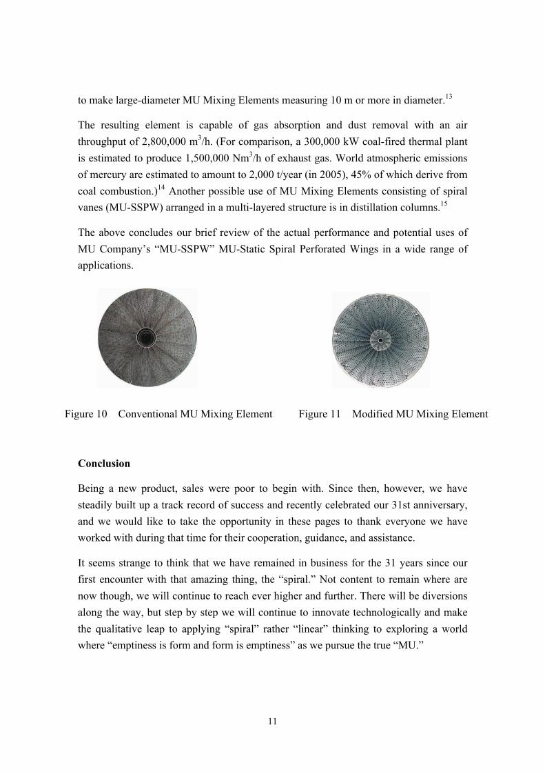
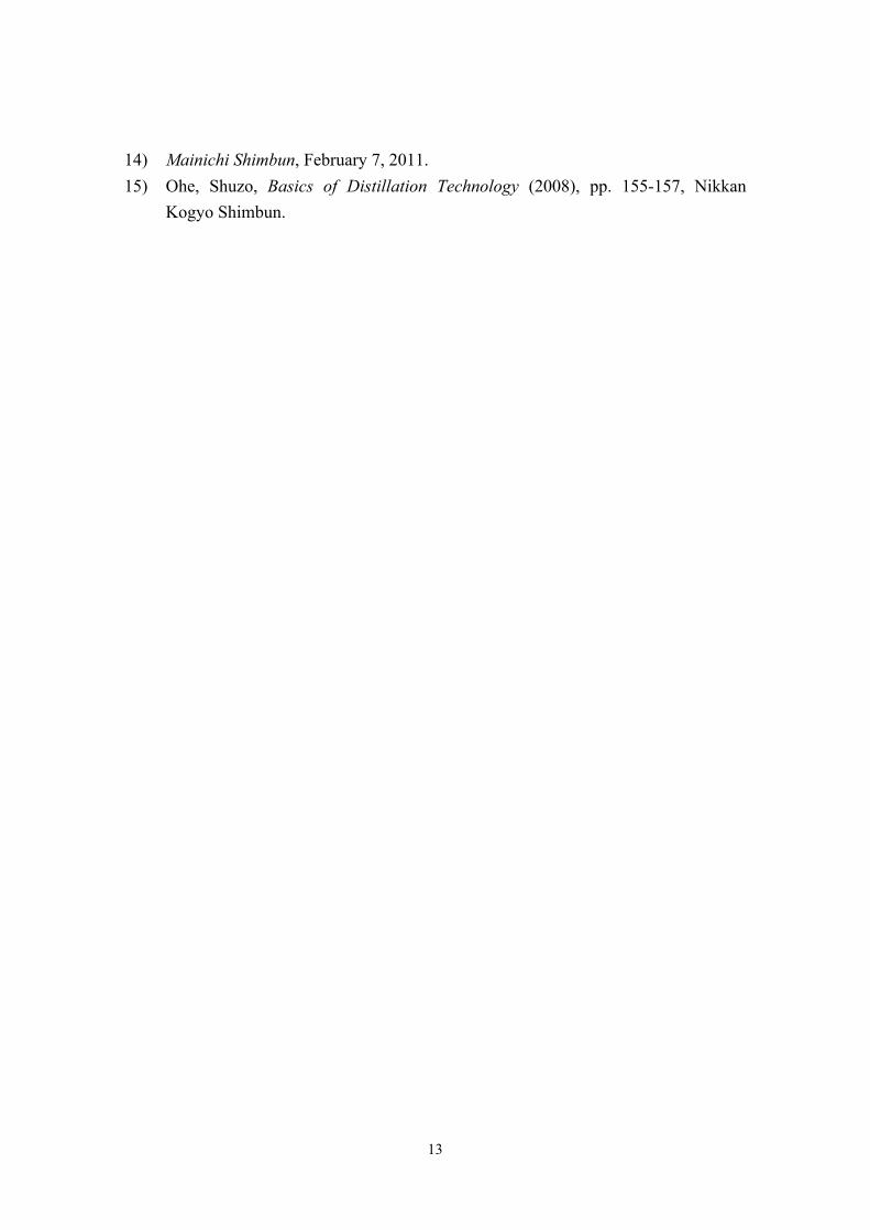
For manufacturing and cost reasons, MU Mixing Elements have until now been limited in size to a diameter of 1,500 mm (Figure 10). By adopting a multi-layered structure of spiraling vanes arranged in concentric circles (Figure 11), however, it becomes possible
Exhaust gas Refined liquid
Make-up feed
Exhaust gas
CO2 absorption tower
Liquid in bottom of
CO2 absorption
tower
Exhaust gas scrubber
To wastewater treatment system
Cooling tower
Supply of absorbent
Feed liquid
Liquid in bottom of CO2 desorption tower
Side reboiler
Heat exchanger
Feed liquid
CO2 desorption tower
Recovered CO2
Absorbent refiner
CO2 desorption tower reflux
Water vapor
Refiner feed liquid
11
to make large-diameter MU Mixing Elements measuring 10 m or more in diameter.13
The resulting element is capable of gas absorption and dust removal with an air throughput of 2,800,000 m3/h. (For comparison, a 300,000 kW coal-fired thermal plant is estimated to produce 1,500,000 Nm3/h of exhaust gas. World atmospheric emissions of mercury are estimated to amount to 2,000 t/year (in 2005), 45% of which derive from coal combustion.)14 Another possible use of MU Mixing Elements consisting of spiral vanes (MU-SSPW) arranged in a multi-layered structure is in distillation columns.15
The above concludes our brief review of the actual performance and potential uses of MU Company’s “MU-SSPW” MU-Static Spiral Perforated Wings in a wide range of applications.
Figure 10 Conventional MU Mixing Element Figure 11 Modified MU Mixing Element
Conclusion
Being a new product, sales were poor to begin with. Since then, however, we have steadily built up a track record of success and recently celebrated our 31st anniversary, and we would like to take the opportunity in these pages to thank everyone we have worked with during that time for their cooperation, guidance, and assistance.
It seems strange to think that we have remained in business for the 31 years since our first encounter with that amazing thing, the “spiral.” Not content to remain where are now though, we will continue to reach ever higher and further. There will be diversions along the way, but step by step we will continue to innovate technologically and make the qualitative leap to applying “spiral” rather “linear” thinking to exploring a world where “emptiness is form and form is emptiness” as we pursue the true “MU.”

12
The summer grasses –
For many brave warriors
The aftermath of dreams.
Matsuo Basho, Oku no Hosomichi (“Hiraizumi”)
Translation: Donald Keene, Travelers of a Hundred Ages, New York, 1999, p. 316
References 1) Kojima, Hisao. Plant and Process, March 2004, pp. 71-75, Kogyo Chosakai
Publishing. 2) Mu Company advertisement in Nature, 396, 5, November 1998. 3) Kojima, Hisao. Plant and Process, July 2008, preface, Kogyo Chosakai
Publishing. 4) Nakano, Yuki. “Measurement of Radon Concentration in Super-Kamiokande
Tank,” University of Tokyo Institute for Cosmic Ray Research, Second Master’s and Doctoral Thesis and Dissertation Defense, February 2013.
5) Furuno, Koichiro. “KamLAND: A Review of Pure Nitrogen Supply Equipment,” April 25, 2003.
6) Shirai, Junpei et al. “The KamLAND Experiment,” High Energy News, 22(1) (2003), pp. 1-10.
7) Tasaka, Shigeki et al. “Measurement of Radon Flux between Atmosphere and Ocean,” National Institute of Polar Research’s 30th Symposium on Polar Meteorology and Glaciology, November 2007.
8) Company Newsletter, Shin-Etsu Chemical, No. 577, p. 5, November 2011. 9) Terasaki, J. et al., “Overcoming the Obstacles,” World Cement, 40, 11, pp.
139-140, 142, 144, November 2009. 10) Kambara, Shinji et al. “Hg0 and NOX Removal in Exhaust by Wet Scrubber with
Static Mixer,” Collected Papers of the Japan Institute of Energy’s 48th Coal Science Symposium, Niigata, pp. 6-7.
11) Kambara, S. et al. “Mercury Emission Control by Wet Scrubber with Super Static Mixer,” 2011 International Pittsburgh Coal Conference, September 2011.
12) Patent Publication Nos. 2006-305510, 2008-132413. 13) USP 7,510, 172B2, EP 1716917, CNP ZL2004 8 0041707.1.
13
14) Mainichi Shimbun, February 7, 2011. 15) Ohe, Shuzo, Basics of Distillation Technology (2008), pp. 155-157, Nikkan
Kogyo Shimbun.