part 2. signs chapter 2d. guide signs - …...2d-1 july, 2013 part 2. signs chapter 2d. guide signs...
TRANSCRIPT

December, 2011
PART 2. SIGNSChapter 2D. Guide Signs - Conventional Roads
TABLE OF CONTENTS
Chapter 2D. GUIDE SIGNS - CONVENTIONAL ROADS PageSection 2D.1 Scope of Conventional Road Guide Sign Standards. . . . . . . . . . . . . . . . . . . . . . . . . . . . . 2D-1
2D.2 Application . . . . . . . . . . . . . . . . . . . . . . . . . . . . . . . . . . . . . . . . . . . . . . . . . . . . . . . . . . . . 2D-12D.3 Color, Retroreflection, and Illumination . . . . . . . . . . . . . . . . . . . . . . . . . . . . . . . . . . . . . . 2D-12D.4 Size of Signs . . . . . . . . . . . . . . . . . . . . . . . . . . . . . . . . . . . . . . . . . . . . . . . . . . . . . . . . . . . 2D-12D.5 Lettering Style . . . . . . . . . . . . . . . . . . . . . . . . . . . . . . . . . . . . . . . . . . . . . . . . . . . . . . . . . . 2D-32D.6 Size of Lettering . . . . . . . . . . . . . . . . . . . . . . . . . . . . . . . . . . . . . . . . . . . . . . . . . . . . . . . . 2D-42D.7 Amount of Legend. . . . . . . . . . . . . . . . . . . . . . . . . . . . . . . . . . . . . . . . . . . . . . . . . . . . . . . 2D-52D.8 Arrows . . . . . . . . . . . . . . . . . . . . . . . . . . . . . . . . . . . . . . . . . . . . . . . . . . . . . . . . . . . . . . . . 2D-52D.9 Numbered Highway Systems . . . . . . . . . . . . . . . . . . . . . . . . . . . . . . . . . . . . . . . . . . . . . . 2D-62D.10 Route Signs and Auxiliary Signs. . . . . . . . . . . . . . . . . . . . . . . . . . . . . . . . . . . . . . . . . . . . 2D-72D.11 Design of Route Signs. . . . . . . . . . . . . . . . . . . . . . . . . . . . . . . . . . . . . . . . . . . . . . . . . . . . 2D-72D.12 Design of Route Sign Auxiliaries . . . . . . . . . . . . . . . . . . . . . . . . . . . . . . . . . . . . . . . . . . . 2D-82D.13 Junction Auxiliary Sign (M2-1) . . . . . . . . . . . . . . . . . . . . . . . . . . . . . . . . . . . . . . . . . . . . 2D-92D.14 Combination Junction Sign (M2-2). . . . . . . . . . . . . . . . . . . . . . . . . . . . . . . . . . . . . . . . . . 2D-92D.15 Cardinal Direction Auxiliary Signs (M3-1 through M3-4). . . . . . . . . . . . . . . . . . . . . . . . 2D-92D.16 Auxiliary Signs for Alternative Routes (M4 Series). . . . . . . . . . . . . . . . . . . . . . . . . . . . . 2D-102D.17 ALTERNATE Auxiliary Signs (M4-1, M4-1a). . . . . . . . . . . . . . . . . . . . . . . . . . . . . . . . . 2D-102D.18 BY-PASS Auxiliary Sign (M4-2a). . . . . . . . . . . . . . . . . . . . . . . . . . . . . . . . . . . . . . . . . . . 2D-102D.19 BUSINESS Auxiliary Sign (M4-3) . . . . . . . . . . . . . . . . . . . . . . . . . . . . . . . . . . . . . . . . . . 2D-102D.20 TRUCK Auxiliary Sign (M4-4) . . . . . . . . . . . . . . . . . . . . . . . . . . . . . . . . . . . . . . . . . . . . 2D-102D.21 TO Auxiliary Sign (M4-5, M4-5a) . . . . . . . . . . . . . . . . . . . . . . . . . . . . . . . . . . . . . . . . . . 2D-102D.22 END Auxiliary Sign (M4-6, M4-6a) . . . . . . . . . . . . . . . . . . . . . . . . . . . . . . . . . . . . . . . . . 2D-112D.23 BEGIN Auxiliary Sign (M4-14, M4-14a) . . . . . . . . . . . . . . . . . . . . . . . . . . . . . . . . . . . . . 2D-112D.24 TEMPORARY Auxiliary Sign (M4-7, M4-7a). . . . . . . . . . . . . . . . . . . . . . . . . . . . . . . . . 2D-112D.25 Temporary Detour and Auxiliary Signs . . . . . . . . . . . . . . . . . . . . . . . . . . . . . . . . . . . . . . 2D-112D.26 Advance Turn Arrow Auxiliary Signs (M5-1, M5-2, M5-3) . . . . . . . . . . . . . . . . . . . . . . 2D-112D.27 Lane Designation Auxiliary Signs (M5-4, M5-5, M5-6) . . . . . . . . . . . . . . . . . . . . . . . . . 2D-122D.28 Directional Arrow Auxiliary Signs (M6 Series) . . . . . . . . . . . . . . . . . . . . . . . . . . . . . . . . 2D-122D.29 Route Sign Assemblies . . . . . . . . . . . . . . . . . . . . . . . . . . . . . . . . . . . . . . . . . . . . . . . . . . . 2D-122D.30 Junction Assembly. . . . . . . . . . . . . . . . . . . . . . . . . . . . . . . . . . . . . . . . . . . . . . . . . . . . . . . 2D-132D.31 Advance Route Turn Assembly. . . . . . . . . . . . . . . . . . . . . . . . . . . . . . . . . . . . . . . . . . . . . 2D-182D.32 Directional Assembly . . . . . . . . . . . . . . . . . . . . . . . . . . . . . . . . . . . . . . . . . . . . . . . . . . . . 2D-192D.33 Combination Lane-Use/Destination Overhead Guide Sign (D15-1) . . . . . . . . . . . . . . . . 2D-192D.34 Confirming or Reassurance Assemblies . . . . . . . . . . . . . . . . . . . . . . . . . . . . . . . . . . . . . . 2D-202D.35 Trailblazer Assembly . . . . . . . . . . . . . . . . . . . . . . . . . . . . . . . . . . . . . . . . . . . . . . . . . . . . . 2D-212D.36 Destination and Distance Signs. . . . . . . . . . . . . . . . . . . . . . . . . . . . . . . . . . . . . . . . . . . . . 2D-212D.37 Destination Signs (D1 Series) . . . . . . . . . . . . . . . . . . . . . . . . . . . . . . . . . . . . . . . . . . . . . . 2D-212D.38 Destination Signs at Circular Intersections . . . . . . . . . . . . . . . . . . . . . . . . . . . . . . . . . . . . 2D-222D.39 Destination Signs at Jughandles . . . . . . . . . . . . . . . . . . . . . . . . . . . . . . . . . . . . . . . . . . . . 2D-232D.40 Location of Destination Signs . . . . . . . . . . . . . . . . . . . . . . . . . . . . . . . . . . . . . . . . . . . . . . 2D-262D.41 Distance Signs (D2 Series) . . . . . . . . . . . . . . . . . . . . . . . . . . . . . . . . . . . . . . . . . . . . . . . . 2D-262D.42 Location of Distance Signs . . . . . . . . . . . . . . . . . . . . . . . . . . . . . . . . . . . . . . . . . . . . . . . . 2D-26
2D-i

2D-iiFebruary, 2018
Page2D.43 Street Name Sign (D3-1 or D3-1a) . . . . . . . . . . . . . . . . . . . . . . . . . . . . . . . . . . . . . . . . . . 2D-272D.44 Advance Street Name Signs (D3-2) . . . . . . . . . . . . . . . . . . . . . . . . . . . . . . . . . . . . . . . . . 2D-282D.45 Signing on Conventional Roads on Approaches to Interchanges . . . . . . . . . . . . . . . . . . . 2D.292D.46 Freeway Entrance Signs (D13-3, D13-3a) . . . . . . . . . . . . . . . . . . . . . . . . . . . . . . . . . . . . 2D-362D.47 Parking Area Guide Sign (D4-1). . . . . . . . . . . . . . . . . . . . . . . . . . . . . . . . . . . . . . . . . . . . 2D-362D.48 PARK - RIDE Sign (D4-2) . . . . . . . . . . . . . . . . . . . . . . . . . . . . . . . . . . . . . . . . . . . . . . . . 2D-362D.49 Weigh Station Signing (D8 Series) . . . . . . . . . . . . . . . . . . . . . . . . . . . . . . . . . . . . . . . . . . 2D-372D.50 Community Wayfinding Signs . . . . . . . . . . . . . . . . . . . . . . . . . . . . . . . . . . . . . . . . . . . . . 2D-372D.51 Truck, Passing, or Climbing Lane Signs (D17-1, D17-2) . . . . . . . . . . . . . . . . . . . . . . . . 2D-432D.52 Slow Vehicle Turn-Out Sign (D17-7) . . . . . . . . . . . . . . . . . . . . . . . . . . . . . . . . . . . . . . . . 2D-432D.53 Signing of Named Highways . . . . . . . . . . . . . . . . . . . . . . . . . . . . . . . . . . . . . . . . . . . . . . 2D-442D.54 Crossover Signs (D13-1, D13-2). . . . . . . . . . . . . . . . . . . . . . . . . . . . . . . . . . . . . . . . . . . . 2D-442D.55 National Scenic Byways Signs (D6-4, D6-4a) . . . . . . . . . . . . . . . . . . . . . . . . . . . . . . . . . 2D-45
FIGURESFigure 2D-1 Examples of Color-Coded Destination Guide Signs. . . . . . . . . . . . . . . . . . . . . . . . . . . . . 2D-3Figure 2D-2 Arrows for Use on Guide Signs . . . . . . . . . . . . . . . . . . . . . . . . . . . . . . . . . . . . . . . . . . . . 2D-4Figure 2D-3 This figure has been eliminatedFigure 2D-4 This figure has been eliminatedFigure 2D-5 This figure has been eliminatedFigure 2D-6 Illustration of Directional Assemblies and Other Route Signs
(For One Direction of Travel Only) (Sheet 1 of 4) . . . . . . . . . . . . . . . . . . . . . . . . 2D-14Figure 2D-6 Illustration of Directional Assemblies and Other Route Signs
(For One Direction of Travel Only) (Sheet 2 of 4) . . . . . . . . . . . . . . . . . . . . . . . . 2D-15Figure 2D-6 Illustration of Directional Assemblies and Other Route Signs
(For One Direction of Travel Only) (Sheet 3 of 4) . . . . . . . . . . . . . . . . . . . . . . . . 2D-16Figure 2D-6 Illustration of Directional Assemblies and Other Route Signs
(For One Direction of Travel Only) (Sheet 4 of 4) . . . . . . . . . . . . . . . . . . . . . . . . 2D-17Figure 2D-7 Destination and Distance Signs. . . . . . . . . . . . . . . . . . . . . . . . . . . . . . . . . . . . . . . . . . . . . 2D-20Figure 2D-8 Destination Signs for Roundabouts. . . . . . . . . . . . . . . . . . . . . . . . . . . . . . . . . . . . . . . . . . 2D-23Figure 2D-9 Examples of Guide Signs for Roundabouts (Sheet 1 of 2) . . . . . . . . . . . . . . . . . . . . . . . 2D-24Figure 2D-9 Examples of Guide Signs for Roundabouts (Sheet 2 of 2) . . . . . . . . . . . . . . . . . . . . . . . 2D-25Figure 2D-10 This figure has been eliminatedFigure 2D-11 Example of Interchange Crossroad Signing for a One-Lane Approach . . . . . . . . . . . . . . 2D-30Figure 2D-12 Example of Minor Interchange Crossroad Signing. . . . . . . . . . . . . . . . . . . . . . . . . . . . . . 2D-31Figure 2D-13 Example of Multi-Lane Crossroad Signing for a Diamond Interchange . . . . . . . . . . . . . 2D-32Figure 2D-14 Example of Multi-Lane Crossroad Signing for a Partial Cloverleaf Interchange . . . . . . 2D-33Figure 2D-15 Example of Multi-Lane Crossroad Signing for a Cloverleaf Interchange . . . . . . . . . . . . 2D-34Figure 2D-16 Example of Crossroad Signing for an Entrance ramp with a Nearby Frontage Road . . . 2D-35Figure 2D-17 Example of Weigh Station Signing . . . . . . . . . . . . . . . . . . . . . . . . . . . . . . . . . . . . . . . . . . 2D-38Figure 2D-18 Example of Community Wayfinding Guide Signs . . . . . . . . . . . . . . . . . . . . . . . . . . . . . . 2D-39Figure 2D-19 Example of a Community Wayfinding Guide Sign System
Showing Direction from a Freeway or Expressway . . . . . . . . . . . . . . . . . . . . . . . . 2D-40Figure 2D-20 Example of a Color-Coded Community Wayfinding Guide Sign System . . . . . . . . . . . . 2D-41
TABLESTable 2D-1 Conventional Road Guide Sign Sizes . . . . . . . . . . . . . . . . . . . . . . . . . . . . . . . . . . . . . . . . 2D-2Table 2D-2 Recommended Minimum Letter Heights on Street Name Signs . . . . . . . . . . . . . . . . . . . 2D-27
MN
Rev
. 6M
N R
ev. 6

July, 20132D-1
PART 2. SIGNSChapter 2D. Guide Signs - Conventional Roads
2D.1 Scope of Conventional RoadGuide Sign Standards
The provisions of this Chapter shall apply to any road orstreet other than low-volume roads (as defined in Section5A.1), expressways, and freeways.
2D.2 Application
Guide signs are essential to direct road users along streetsand highways, to inform them of intersecting routes, todirect them to cities, towns, villages, or other important des-tinations, to identify nearby rivers and streams, parks,forests, and historical sites, and generally to give suchinformation as will help them along their way in the mostsimple, direct manner possible.
Chapter 2A addresses placement, location, and othergeneral criteria for signs.
2D.3 Color, Retroreflection, andIllumination
Requirements for illumination, retroreflection, and colorare stated under the specific headings for individual guidesigns or groups of signs. General provisions are given inSections 2A.7, 2A.8, and 2A.10.
Except where otherwise provided in this Manual forindividual signs or groups of signs, guide signs on streetsand highways shall have a white message and border on agreen background. All messages, borders, and legends shallbe retroreflective and all backgrounds shall be retroreflec-tive or illuminated.
Color coding is sometimes used to help road usersdistinguish between multiple potentially confusing destina-tions. Examples of valuable uses of color coding includeguide signs for roadways approaching or inside an airportproperty with multiple terminals serving multiple airlines,and community wayfinding guide signs for various trafficgenerator destinations within a community or area.
STANDARD:STANDARD:
STANDARD:STANDARD:
SUPPORT:SUPPORT:
SUPPORT:SUPPORT:
SUPPORT:SUPPORT:
Except where otherwise provided in this Manual,different color sign backgrounds shall not be used to providecolor coding of destinations. The color coding shall beaccomplished by the use of different colored square orrectangular sign panels on the face of the guide signs.
The different colored sign panels may include a black orwhite (whichever provides the better contrast with the panelcolor) letter, numeral, or other appropriate designation toidentify an airport terminal or other destination.
Two examples of color-coded sign assemblies are shownin Figure 2D-1. Section 2D.50 contains specific provisionsregarding Community Wayfinding guide signs.
2D.4 Size of Signs
Except as provided in Section 2A.11, the sizes of conven-tional road guide signs that have standardized designs shallbe as shown in Table 2D-1.
Section 2A.11 contains information regarding the applic-ability of the various columns in Table 2D-1.
Signs larger than those shown in Table 2D-1 may be used(see Section 2A.11).
For other guide signs, the legends are so variable that a stan-dardized design or size is not appropriate. The sign size isdetermined primarily by the length of the message, and thesize of lettering and spacing necessary for proper legibility.
SUPPORT:SUPPORT:
OPTION:OPTION:
SUPPORT:SUPPORT:
STANDARD:STANDARD:
SUPPORT:SUPPORT:
STANDARD:STANDARD:
OPTION:OPTION:
MN
Rev
. 2

Table 2D-1. Conventional Road Guide Sign Sizes
2D-2December, 2011

Reduced letter height, reduced interline spacing, andreduced edge spacing may be used on guide signs if sign sizemust be limited by factors such as lane width or vertical orlateral clearance.
Reduced spacing between the letters or words on a line oflegend should not be used as a means of reducing the overallsize of a guide sign, except where determined necessary byengineering judgment to meet unusual lateral spaceconstraints. In such cases, the legibility distance of the signlegend should be the primary consideration in determiningwhether to reduce the spacing between the letters or thewords or between the words and the sign border, or to reducethe letter height.
When a reduction in the standard size is necessary, thedesign used should be as similar as possible to the design forthe standard size.
OPTION:OPTION:
GUIDANCE:GUIDANCE:
2D.5 Lettering Style
The design of upper-case letters, lower-case letters,numerals, route shields, and spacing shall be as provided inthe MnDOT “Standard Signs Manual”, and the Federal"Standard Highway Signs and Markings" book (see Section1A.11).
The lettering for names of places, streets, and highwayson conventional road guide signs shall be a combination oflower-case letters with initial upper-case letters (see Section2A.13). The nominal loop height of the lower-case lettersshall be 3/4 the height of the initial upper-case letter. Whena mixed-case legend letter height is specified referring onlyto the initial upper-case letter, the height of the lower-caseletters that follow shall be determined by this proportion.When the height of a lower-case letter is referenced, thereference is made to the nominal loop height and the heightof the initial upper-case letter shall also be determined bythis proportion.
All other word legends on conventional road guide signsshall be in upper-case letters.
The unique letter forms for each of the Standard Alphabetseries shall not be stretched, compressed, warped, orotherwise manipulated. Modifications to the length of aword for a given letter height and series shall be accom-plished only by the methods described in Section 2D.4.
STANDARD:STANDARD:
Figure 2D-1. Examples of Color-Coded Destination Guide Signs
B u d g et A i r Pa n At l a n t i c
Ex p ress A i r A l p h a A i r
A i r M i dwest E a ste r n O r i e n t
N EXT LEFT
A B
A - Freeway or Expressway - Airport Terminals
B - Conventional Road or Street - Urban Areas
H a n ove r
T h ea te r D i st r i c tD ow n tow n
D i st r i c ts
2D-3 December, 2011

2D-4December, 2011
2D.6 Size of Lettering
Sign legibility is a direct function of letter size andspacing. Legibility distance has to be sufficient to give roadusers enough time to read and comprehend the sign. Underoptimum conditions, a guide sign message can be read andunderstood in a brief glance. The legibility distance takesinto account factors such as inattention, blocking of view byother vehicles, unfavorable weather, inferior eyesight, orother causes for delayed or slow reading. Where conditionspermit, repetition of guide information on successive signsgives the road user more than one opportunity to obtain theinformation needed.
Design layouts for conventional road guide signs showinginterline spacing, edge spacing, and other specificationdetails shall be as shown in the MnDOT “Standard SignsManual”, and the Federal "Standard Highway Signs andMarkings" book (see Section 1A.11).
STANDARD:STANDARD:
SUPPORT:SUPPORT:
The principal legend on guide signs shall be in letters andnumerals at least 6 inches in height for all upper-case letters,or a combination of 6 inches in height for upper-case lettersand 4.5 inches in height for lower-case letters. On low-volume roads (as defined in Section 5A.1) with speeds of 25mph or less, and on urban streets with speeds of 25 mph orless, the principal legend shall be in letters at least 4 inchesin height for all upper-case letters, or a combination of 4inches in height for upper-case letters and 3 inches in heightfor lower-case letters.
Lettering sizes should be consistent on any particularclass of highway.
The minimum lettering sizes provided in this Manualshould be exceeded where conditions indicate a need forgreater legibility..
Guidelines for designing guide signs can be found in theMinnesota Traffic Engineering Manual, Chapter 6, Charts6.1A through 6.1E.
SUPPORT:SUPPORT:
GUIDANCE:GUIDANCE:
Figure 2D-2. Arrows for Use on Guide Signs
Directional Arrows
Down Arrow
Type A
Note: The “Standard Highway Signsand Markings” book contains thedetails of these arrow designs.
Type A - Extended Type B Type C Type D

2D-5 December, 2011
2D.7 Amount of Legend
The longer the legend on a guide sign, the longer it willtake road users to comprehend it, regardless of letter size.
Except where otherwise provided in this Manual, guidesigns should be limited to no more than three lines of desti-nations, which include place names, route numbers, streetnames, and cardinal directions. Where two or more signs areincluded in the same overhead display, the amount of legendshould be further minimized. Where appropriate, a distancemessage or action information, such as an exit number,NEXT RIGHT, or directional arrows, should be provided onguide signs in addition to the destinations.
2D.8 Arrows
Arrows are used for lane assignment and to indicate thedirection toward designated routes or destinations. Figure2D-2 shows the various standard arrow designs that havebeen approved for use on guide signs. Detailed drawings ofthese standard arrows are shown in the MnDOT “StandardSigns Manual”, and the Federal "Standard Highway Signsand Markings" book (see Section 1A.11).
On overhead signs where it is desirable to indicate a laneto be followed, a down arrow shall be positioned approxi-mately over the center of the lane and shall point verticallydownward toward the approximate center of that lane. Downarrows shall be used only on overhead guide signs thatrestrict the use of specific lanes to traffic bound for thedestination(s) and/or route(s) indicated by these arrows.Down arrows shall not be used unless an arrow can belocated over and pointed to the approximate center of eachlane that can be used to reach the destination displayed onthe sign.
If down arrows are used, having more than one downarrow pointing to the same lane on a single overhead sign (oron multiple signs on the same overhead sign structure) shallnot be permitted.
Where a roadway is leaving the through lanes, adirectional arrow shall point upward at an angle that approx-imates the alignment of the exit roadway.
Curved-stem arrows (see Figure 2D-8) that represent theintended driver paths to destinations involving left-turnmovements may be used on guide signs on approaches tocircular intersections.
OPTION:OPTION:
STANDARD:STANDARD:
SUPPORT:SUPPORT:
GUIDANCE:GUIDANCE:
SUPPORT:SUPPORT:Curved-stem arrows shall not be used on any sign that is
not associated with a circular intersection.
If curved-stem arrows are used, the principles set forth inSections 2D.26 through 2D.29 should be followed.
The Type A directional arrow should be used on guidesigns on freeways, expressways, and conventional roads toindicate the direction to a specific destination or group ofdestinations, except as otherwise provided in this Sectionand in Section 2E.19.
When a directional arrow in a vertical, upward-pointingorientation is placed to the side of a group of destinations toindicate a through movement, the Type A directional arrowshould be used. When a directional arrow in a vertical,upward-pointing orientation is placed to the side of a singledestination or under a destination or group of destinations,the Type B directional arrow should be used.
The Type B directional arrow should be used on guidesigns on conventional roads when placed at any angle to theside of a single destination or when placed in a horizontalorientation to the side of a group of destinations.
The Type C advance turn directional arrow should beused on conventional road guide signs placed in advance ofan intersection where a turn must be made to reach a posteddestination or group of destinations.
The Type D directional arrow should be used primarilyfor sign applications other than guide signs, except asprovided in paragraph four of the following Option.
The Type A-Extended directional arrow may be used onguide signs where additional emphasis regarding thedirection is needed relative to the amount of legend on thesign.
The Type C directional arrow may be used to the side ofthe legend of an overhead guide sign to accentuate a sharpturn exit maneuver from a mainline roadway (see Section2E.36 for additional information regarding Exit Directionsigns for low advisory ramp speeds).
On conventional roads on the approach to an intersectionwhere the Combination Lane-Use/Destination overheadguide sign (see Section 2D.33) is not used, the Type Cadvance turn directional arrow may be used beneath thelegend of an overhead guide sign to indicate the fact that aturn must be made from a mandatory movement lane overwhich the sign is placed to reach the destination or destina-tions displayed on the sign.
OPTION:OPTION:
GUIDANCE:GUIDANCE:
STANDARD:STANDARD:
2D-6December, 2011
The Type D directional arrow may be used on post-mounted guide signs on conventional roads with loweroperating speeds if the height of the text on the sign is 8inches or less.
The directional and down arrows shown in Figure 2D-2may be used on signs other than guide signs for the purposesof providing directional guidance and lane assignment.
Arrows used on guide signs to indicate the directionstoward designated routes or destinations should be pointedat the appropriate angle to clearly convey the direction to betaken. A horizontally oriented directional arrow designshould be used at right-angle intersections.
On a post-mounted guide sign, a directional arrow for astraight-through movement should point upward. Except asprovided in Section 2D.46, for a turn, the arrow on a guidesign should point horizontally or at an upward angle thatapproximates the sharpness of the turn.
At an exit, an arrow should be placed at the side of thesign that will reinforce the movement of exiting traffic. Thedirectional arrow design should be used.
Arrows may be placed below the principal sign legend oron the appropriate side of the legend.
On a post-mounted sign at an exit where placement of thearrow to the side of the legend farthest from the roadwaywould create an unusually wide sign that limits the roaduser's view of the arrow, the directional arrow may be placedat the bottom portion of the sign, centered under the legend.
The width across the arrowhead for the Types A, B, and Cdirectional arrows should be between 1.5 and 1.75 times theheight of the upper-case letters of the principal legend on thesign. The width across the arrowhead for the Type Ddirectional arrow should be at least equal to the height of theupper-case letters of the principal legend on the sign. Fordown arrows used on overhead signs, the width across thearrowhead should be approximately two times the height ofthe upper-case letters of the principal legend on the sign.
Arrows used in Overhead Arrow-per-Lane andDiagrammatic guide signing, if used on conventional roads,except for signs on approaches to roundabouts, shouldfollow the principles set forth in Section 2E.19.Arrows usedin Diagrammatic guide signing on approaches toroundabouts should follow the principles set forth in Section2D.38.
GUIDANCE:GUIDANCE:
OPTION:OPTION:
GUIDANCE:GUIDANCE:
The MnDOT "Standard Signs Manual" and the Federal"Standard Highway Signs and Markings" book (see Section1A.11) contain design details and standardized sizes of thevarious arrows based on ranges of letter heights of principallegends.
2D.9 Numbered Highway Systems
The purpose of numbering and signing highway systemsis to identify routes and facilitate travel.
The Interstate and United States (U.S.) highway systemsare numbered by the American Association of StateHighway and Transportation Officials (AASHTO) upon rec-ommendations of the State highway organizations becausethe respective States own these systems. State and countyroad systems are numbered by the appropriate authorities.
The basic policy for numbering the Interstate and U.S.highway systems is contained in the following Purpose andPolicy statements published by AASHTO (see Page i forAASHTO's address):
A. "Establishment and Development of United StatesNumbered Highways;" and
B. "Establishment of a Marking System of the RoutesComprising the National System of Interstate andDefense Highways."
The principles of these policies should be followed inestablishing the highway systems described in Paragraphtwo of the above Support and any other systems, witheffective coordination between adjacent jurisdictions. Careshould be taken to avoid the use of numbers or other desig-nations that have been assigned to Interstate, U.S., or Stateroutes in the same geographic area. Overlapping numberedroutes should be kept to a minimum.
Route systems shall be given preference in this order:Interstate, United States, State, and County. The preferenceshall be given by installing the highest-priority legend on thetop or the left of the sign.
Section 2D.53 contains information regarding the signingof unnumbered highways to enhance route guidance andfacilitate travel.
SUPPORT:SUPPORT:
STANDARD:STANDARD:
GUIDANCE:GUIDANCE:
SUPPORT:SUPPORT:
SUPPORT:SUPPORT:

2D-7 December, 2011
2D.10 Route Signs and Auxiliary Signs
All numbered highway routes shall be identified by routesigns and auxiliary signs.
The signs for each system of numbered highways, whichare distinctive in shape and color, shall be used only on thatsystem and the approaches thereto.
Route signs and auxiliary signs may be proportionallyenlarged where greater legibility is needed.
Route signs are typically mounted in assemblies withauxiliary signs.
Section 2D.55 contains information regarding the signingfor National Scenic Byways.
Section 2H.7 contains information regarding the signingfor Auto Tour Routes.
2D.11 Design of Route Signs
The MnDOT "Standard Signs Manual" shall be used fordesigning route signs. Other route sign designs shall beestablished by the authority having jurisdiction.
Interstate Route signs shall consist of a cutout shield, withthe route number in white letters on a blue background, theword INTERSTATE in white upper-case letters on a redbackground, and a white border. This sign shall be used onall Interstate routes and in connection with route signassemblies on intersecting highways.
A 24 x 24-inch minimum sign size shall be used forInterstate route numbers with one or two digits, and a 30 x24-inch minimum sign size shall be used for Interstate routenumbers having three digits.
Interstate Route signs may contain the State name inwhite upper-case letters on a blue background.
OPTION:OPTION:
M1-1 M1-2 & M1-3
94
I NTERSTATE
94
B U S I N ESSLOO P
STANDARD:STANDARD:
SUPPORT:SUPPORT:
OPTION:OPTION:
STANDARD:STANDARD: Off-Interstate Business Route signs shall consist of acutout shield carrying the number of the connectingInterstate route and the words BUSINESS and either LOOPor SPUR in upper-case letters. The legend and border shallbe white on a green background, and the shield shall be thesame shape and dimensions as the Interstate Route sign. Inno instance shall the word INTERSTATE appear on the Off-Interstate Business Route sign.
The Off-Interstate Business Route sign may be used on amajor highway that is not a part of the Interstate system, butone that serves the business area of a city from aninterchange on the system. When used on a green guide sign,a white square or rectangle may be placed behind the shieldto improve contrast.
U.S. Route signs shall consist of black numerals on awhite shield surrounded by a rectangular black backgroundwithout a border. This sign shall be used on all U.S. routesand in connection with route sign assemblies on intersectinghighways.
A 24 x 24-inch minimum sign size shall be used for U.S.route numbers with one or two digits, and a 30 x 24-inchminimum sign size shall be used for U.S. route numbershaving three digits.
The Minnesota Route Marker (M1-5a & M1-5b) shall berectangular with white numerals on a blue background witha gold border. The silhouette and the name of the state shallbe in blue on a gold band across the top of the routemarker.
Where U.S. or State Route signs are used as componentsof guide signs, only the distinctive shape of the shield itselfand the route numerals within should be used. Therectangular background upon which the distinctive shape ofthe shield is mounted, such as the black area around the
GUIDANCE:GUIDANCE:
STANDARD:STANDARD:
M1-4 M1-5b
6 1
STANDARD:STANDARD:
OPTION:OPTION:
STANDARD:STANDARD:

2D-8December, 2011
outside of the shields on the M1-4 and standard M1-5a orM1-5b signs, should not be included on the guide sign.Where U.S. or State Route signs are used as components ofother signs of non-contrasting background colors, therectangular background should be used to so that recognitionof the distinctive shape of the shield can be maintained.
The standard County Route Marker (M1-X4) approvedfor general use on county highways in Minnesota shall besquare with the county name at the top, the route numberin the center and the word “COUNTY” at the bottom. Thelegend and border shall be black on a white background.The standard size for all applications shall be 24 x 24inches. When used with other route markers in commonassemblies, the County Route Marker shall be of a sizecompatible with that of the other route markers.
If county road authorities elect to establish and identify aspecial system of important county roads, a statewide policyfor such signing shall be established that includes a uniformnumbering system to uniquely identify each route. TheCounty Route (M1-6) sign shall consist of a pentagon shapewith a yellow county name and border, a white route letteror number on a blue background. County Route signsdisplaying two digits or the equivalent (letter and numeral,or two letters) shall be a minimum size of 18 x 18 inches;those carrying three digits or the equivalent shall be aminimum size of 24 x 24 inches.
When used with other route markers in commonassemblies, the M1-X4 County Route Marker shall be of athe same size compatible with as that of the other routemarkers.
If a jurisdiction uses letters instead of numbers to identifyroutes, all references to numbered routes in this Chaptershall be interpreted to also include lettered routes.
If used with other route signs in common assemblies, theCounty Route sign should be of a size compatible with thatof the other route signs.
GUIDANCE:GUIDANCE:
M1-X4 M1-6
CARVER
CO U NTY
5 44WR I G HT
CO U NTY
STANDARD:STANDARD:
When used on a green guide sign, a yellow square orrectangle may be placed behind the pentagon shapedCounty Route (M1-6) sign to improve contrast.
The Township Route Marker (M1-X3) shall be squarewith the abbreviation “TWP”, the appropriate route number,and the border in black on a white background. Thestandard size for all applications shall be 24 x 24 inches.Reassurance markers may be a minimum size of 18 x 18inches. When used with other route markers in commonassemblies, the Township Route Marker shall be of a sizecompatible with that of the other route markers.
Route signs for park and forest roads shall be designedwith adequate distinctiveness and legibility and of a sizecompatible with other route signs used in commonassemblies.
2D.12 Design of Route Sign Auxiliaries
Route sign auxiliaries carrying word legends, except theJCT sign, shall have a standard size of 24 x 12 inches. Thosecarrying arrow symbols, or the JCT sign, shall have astandard size of 21 x 15 inches. All route sign auxiliariesshall match the color combination of the route sign that theysupplement.
With route signs of larger heights, auxiliary signs shouldbe suitably enlarged, but not such that they exceed the widthof the route sign.
For a route sign design that uses multiple backgroundcolors, such as the Interstate route sign, the backgroundcolor of the corresponding auxiliary should be that of thebackground area on which the route number is placed on theroute sign..
GUIDANCE:GUIDANCE:
STANDARD:STANDARD:
M1-X3 M1-7
TWP
2 11 3
STANDARD:STANDARD:
OPTION:OPTION:

2D-9 July, 2013
A route sign and any auxiliary signs used with it may becombined on a single sign as a guide sign.
If a route sign and its auxiliary signs are combined toform a single guide sign, the background color of the signshould be green and the design should comply with the basicprinciples for the design of guide signs.
If a route sign and its auxiliary signs are combined on asingle sign with a green background, the auxiliary messagesshall be white legends placed directly on the greenbackground. Auxiliary signs shall not be mounted directly toa guide sign or other type of sign.
Chapter 2F contains information regarding auxiliary signsfor toll highways.
2D.13 Junction Auxiliary Sign (M2-1)
The Junction (M2-1) auxiliary sign shall carry theabbreviated legend JCT and shall be mounted at the top ofan assembly (see Section 2D.30) directly above the routesign, the sign for an alternative route (see Section 2D.17)that is part of the route designation, or the Cardinal Directionauxiliary sign where access is available only to one directionof the intersected route. The minimum size of the Junctionauxiliary sign shall be 21 x 15 inches for compatibility withauxiliary signs carrying arrow symbols.
2D.14 Combination Junction Sign (M2-2)
As an alternative to the standard Junction assembly wheremore than one route is to be intersected or joined, arectangular guide sign may be used carrying the wordJUNCTION above the route numbers.
The Combination Junction (M2-2) sign shall have a greenbackground with white border and lettering for the wordJUNCTION.
STANDARD:STANDARD:
OPTION:OPTION:
STANDARD:STANDARD:
M2-1 M2-1a
SUPPORT:SUPPORT:
STANDARD:STANDARD:
GUIDANCE:GUIDANCE:
OPTION:OPTION:
The Combination Junction sign should comply with thespecific provisions of Section 2D.11 regarding the incorpo-ration of the route signs as components of guide signs.
Although the size of the Combination Junction sign willdepend on the number of routes involved, the numeralsshould be large enough for clear legibility and should be ofa size comparable with those in the individual route signs.
2D.15 Cardinal Direction Auxiliary Signs(M3-1 through M3-4)
Cardinal Direction auxiliary signs carrying the legendNORTH, EAST, SOUTH, or WEST should be used toindicate the general direction of the entire route.
To improve the readability and recognition of the cardinaldirections, the first letter of the cardinal direction wordsshall be ten percent larger, rounded up to the nearest wholenumber size.
If used, the Cardinal Direction auxiliary sign shall bemounted directly above a route sign or, if used, an auxiliarysign for an alternative route.
STANDARD:STANDARD:
GUIDANCE:GUIDANCE:
M3-4 M3-4a
WEST WWESTEST
M3-1a M3-2a M3-3a
NN O RTHO RTH EE ASTAST SS O UTHO UTH
M3-1 M3-2 M3-3
N O RTH E AST S O UTH
GUIDANCE:GUIDANCE:
M2-2
4 7
J U N CT I O N
MN
Rev
. 2M
N R
ev. 2

2D-10December, 2011
2D.16 Auxiliary Signs for AlternativeRoutes (M4 Series)
Auxiliary signs, carrying legends such as ALTERNATE,BY-PASS, BUSINESS, or TRUCK, may be used to indicatean alternate route of the same number between two points onthat route.
If used, the auxiliary signs for alternative routes shall bemounted directly above a route sign.
2D.17 ALTERNATE Auxiliary Signs(M4-1, M4-1a)
The ALTERNATE (M4-1) or the ALT (M4-1a) auxiliarysign may be used to indicate an officially designatedalternate routing of a numbered route between two points onthat route.
If used, the ALTERNATE or ALT auxiliary sign shall bemounted directly above a route sign.
The shorter (time or distance) or better-constructed routeshould retain the regular route number, and the other routeshould be designated as the alternate route.
2D.18 BY-PASS Auxiliary Sign (M4-2a)
The BY-PASS (M4-2a) auxiliary sign may be used todesignate a route that branches from the numbered routethrough a city, bypasses a part of the city or congested area,and rejoins the numbered route beyond the city.
If used, the BY-PASS auxiliary sign shall be mounteddirectly above a route sign.
STANDARD:STANDARD:
OPTION:OPTION:
M4-2a
B Y P A S S
GUIDANCE:GUIDANCE:
STANDARD:STANDARD:
OPTION:OPTION:
M4-1 M4-1a
A LT E R N AT E ALT
STANDARD:STANDARD:
OPTION:OPTION:
2D.19 BUSINESS Auxiliary Sign (M4-3)
The BUSINESS (M4-3) auxiliary sign may be used todesignate an alternate route that branches from a numberedroute, passes through the business portion of a city, andrejoins the numbered route beyond that area.
If used, the BUSINESS auxiliary sign shall be mounteddirectly above a route sign.
2D.20 TRUCK Auxiliary Sign (M4-4)
The TRUCK (M4-4) auxiliary sign may be used todesignate an alternate route that branches from a numberedroute, when it is desirable to encourage or requirecommercial vehicles to use the alternate route.
If used, the TRUCK auxiliary sign shall be mounteddirectly above a route sign.
2D.21 TO Auxiliary Sign (M4-5, M4-5a)
The TO (M4-5) auxiliary sign may be used to providedirectional guidance to a particular road facility from otherhighways in the vicinity (see Section 2D.35).
If used, the TO auxiliary sign shall be mounted directlyabove a route sign or an auxiliary sign for an alternativeroute. If a Cardinal Direction auxiliary sign is also includedin the assembly, the TO auxiliary sign shall be mounteddirectly above the Cardinal Direction auxiliary sign.
STANDARD:STANDARD:
OPTION:OPTION:
M4-5 M4-5a
T O T O
STANDARD:STANDARD:
OPTION:OPTION:
M4-4
T R U C K
STANDARD:STANDARD:
OPTION:OPTION:
M4-3
B U S I N E S S

2D-11 December, 2011
2D.22 END Auxiliary Sign (M4-6, M4-6a)
The END (M4-6) auxiliary sign should be used where theroute being traveled ends, usually at a junction with anotherroute.
If used, the END auxiliary sign shall be mounted eitherdirectly above a route sign or above a sign for an alternativeroute that is part of the designation of the route beingterminated.
2D.23 BEGIN Auxiliary Sign(M4-14, M4-14a)
The BEGIN (M4-14) auxiliary sign may be used where aroute begins, usually at a junction with another route.
If used, the BEGIN auxiliary sign shall be mounted at thetop of the first Confirming assembly (see Section 2D.34) forthe route that is beginning.
If a BEGIN auxiliary sign is included in the firstConfirming assembly, a Cardinal Direction auxiliary signshould also be included in the assembly.
If a Cardinal Direction auxiliary sign is also included inthe assembly, the BEGIN auxiliary sign shall be mounteddirectly above the Cardinal Direction auxiliary sign.
STANDARD:STANDARD:
GUIDANCE:GUIDANCE:
STANDARD:STANDARD:
OPTION:OPTION:
M4-14 M4-14a
B EG I N B EG I N
STANDARD:STANDARD:
GUIDANCE:GUIDANCE:
M4-6 M4-6a
E N D E N D
2D.24 TEMPORARY Auxiliary Sign(M4-7, M4-7a)
The TEMPORARY (M4-7) or the TEMP (M4-7a)auxiliary sign may be used for an interim period to designatea section of highway that is not planned as a permanent partof a numbered route, but that connects completed portions ofthat route.
If used, the TEMPORARY or TEMP auxiliary sign shallbe mounted directly above the route sign, above a CardinalDirection sign, or above a sign for an alternate route that isa part of the route designation.
TEMPORARY or TEMP auxiliary signs shall bepromptly removed when the temporary route is abandoned.
2D.25 Temporary Detour andAuxiliary Signs
Chapter 6F contains information regarding TemporaryDetour and Auxiliary signs.
2D.26 Advance Turn Arrow Auxiliary Signs(M5-1, M5-2, and M5-3)
If used, the Advance Turn Arrow auxiliary sign shall bemounted directly below the route sign in Advance RouteTurn assemblies, and displays a right or left arrow, the shaftof which is bent at a 90-degree angle (M5-1) or at a 45-degree angle (M5-2).
STANDARD:STANDARD:
M5-1a M5-2a M5-3a
M5-1 M5-2 M5-3
SUPPORT:SUPPORT:
STANDARD:STANDARD:
OPTION:OPTION:
M4-7 M4-7a
T E M P O R A R Y T E M P

2D-12July, 2013
If used, the curved-stem Advance Turn Arrow auxiliary(M5-3) sign shall be used only on the approach to a circularintersection to depict a movement along the circulatoryroadway around the central island and to the left, relative tothe approach roadway and entry into the intersection.
If the M5-3 sign is used, then this arrow type should alsobe used consistently on any regulatory lane-use signs (seeChapter 2B), Destination signs (see Section 2D.37), andpavement markings (see Part 3) for a particular destinationor movement.
2D.27 Lane Designation Auxiliary Signs(M5-4, M5-5, and M5-6)
A Lane Designation (M5-4, M5-5, or M5-6) auxiliarysign may be mounted directly below the route sign in anAdvance Route Turn assembly on multi-lane roadways toallow road users to move into the appropriate lane prior toreaching the intersection or interchange.
If used, the Lane Designation auxiliary signs shall be usedonly where the designated lane is a mandatory movementlane and shall be located adjacent to the full-width portion ofthe mandatory movement lane. The Lane Designationauxiliary signs shall not be installed adjacent to a throughlane in advance of a lane that is being added or along thetaper for a lane that is being added.
2D.28 Directional Arrow Auxiliary Signs(M6 Series)
GUIDANCE:GUIDANCE:
M5-6M5-5M5-4
M5-6aM5-5aM5-4a
OPTION:OPTION:
STANDARD:STANDARD:
M6-3M6-2M6-1
M6-3aM6-2aM6-1a
If used, the Directional Arrow auxiliary sign shall bemounted below the route sign and any other auxiliary signsin Directional assemblies (see Section 2D.32), and displaysa single- or double-headed arrow pointing in the generaldirection that the route follows.
A Directional Arrow auxiliary sign that displays a double-headed arrow shall not be mounted in any Directionalassembly in advance of or at a circular intersection.
The downward pointing diagonal arrow auxiliary (M6-2a) sign may be used in a Directional assembly at the farcorner of an intersection to indicate the immediate entrypoint to a freeway or expressway entrance ramp (see Section2D.46).
The M6-2a sign shall not be used on the approach to or onthe near side of an intersection, such as to designate anapproach lane.
2D.29 Route Sign Assemblies
A Route Sign assembly shall consist of a route sign andauxiliary signs that further identify the route and indicate thedirection. Route Sign assemblies shall be installed on allapproaches to signed numbered routes that intersect withother signed numbered routes.
Where two or more routes follow the same section ofhighway, the route signs for Interstate, U.S., State, andCounty routes shall be mounted in that order from the left in
M6-6M6-5M6-4
M6-6aM6-5aM6-4a
M6-7aM6-7
STANDARD:STANDARD:
OPTION:OPTION:
STANDARD:STANDARD:
STANDARD:STANDARD:
MN
Rev
. 2

2D-13 December, 2011
horizontal arrangements and from the top in verticalarrangements. Subject to this order of precedence, routesigns for lower-numbered routes shall be placed at the left ortop.
Within groups of assemblies, information for routes inter-secting from the left shall be mounted at the left inhorizontal arrangements and at the top or center of verticalarrangements. Similarly, information for routes intersectingfrom the right shall be at the right or bottom, and forstraight-through routes at the center in horizontal arrange-ments or top in vertical arrangements.
94
I NTERSTATE
6 1
5 3
Route Markers Arranged byClass of Highway
6 11 0
23
68
Route Markers Arranged by NumberWithin the Class of Highway
1 0
6 85 3
23
6 194
I NTERSTATE
Route Markers Arranged byDirectional Arrows
Route Sign assemblies shall be mounted in accordancewith the general specifications for highway signs (Chapter2A), with the lowest sign in the assembly at the heightprescribed for single signs.
Assemblies for two or more routes, or for differentdirections on the same route, should be mounted in groupson a common support.
Route Sign assemblies may be installed on theapproaches to numbered routes on unnumbered roads andstreets that carry an appreciable amount of traffic destinedfor the numbered route.
The diagrammatic route guide sign format, such as theD1-4 and D1-5 signs shown in Figure 2D-8, may be used onapproaches to roundabouts.
If engineering judgment indicates that groups ofassemblies that include overlapping routes or multiple turnsmight be confusing, route signs or auxiliary signs may beomitted or combined, provided that clear directions aregiven to road users.
Figure 2D-6 shows typical placements of route signs.
2D.30 Junction Assembly
A Junction assembly shall consist of a Junction auxiliarysign and a route sign. The route sign shall carry the numberof the intersected or joined route.
The Junction assembly shall be installed in advance ofevery intersection where a signed numbered route isintersected or joined by another signed numbered route.
6 1 6 3
2 543
27
N O RTH S O UTHSS O UTHO UTH
Route Markers Arranged byCommon Direction
GUIDANCE:GUIDANCE:
OPTION:OPTION:
SUPPORT:SUPPORT:
STANDARD:STANDARD:

2D-14December, 2011
Figure 2D-6. Illustration of Directional Assemblies and Other Route Signs(For One Direction of Travel Only)
(Sheet 1 of 4)
STATE ROUTE28
STATE ROUTE20
STATE ROUTE50
U.S. ROUTE61
U.S. ROUTE75
U.S. ROUTE75
U.S. ROUTE61
STATE ROUTE28
25 to 2
00 feet
25 to 2
00 feet
100 to 2
00 feet
100 to 2
00 feet
300 feet
+
300 feet
+N
ot le
ss than 4
00 feet
Not le
ss than 4
00 feet
7 5
7 5
6 1
2 8
7 528
28
6 1 20
6 1 2 0
C o l l i s 51 7W h e a t o n
M i e sv i l l e 21 7R e d W i n g
M i e s v i l l e
H a s t i n g s
C a n n o n Fa l l s
6 1 2 0
J U N CT I O N
(Duplicate Optional) (Duplicate Optional)
Note: The spacings shown on this figure are for rural intersections.See Sections 2D.29, 2D.30, 2D.32 2D.34, 2D.40, and 2D.42for low-speed and/or urban conditions.
N O RTH
N O RTH
N O RTH
B a r ry
J o h n s o n
WWESTEST
WWESTEST
S O UTH

2D-15 December, 2011
Figure 2D-6. Illustration of Directional Assemblies and Other Route Signs(For One Direction of Travel Only)
(Sheet 2 of 4)
STATE ROUTE30
U.S. ROUTE59
U.S. ROUTE14
U.S. ROUTE14
U.S. ROUTE59
STATE ROUTE68
STATE ROUTE4
STATE ROUTE4 & 68
25
to
20
0 f
ee
t
25
to
20
0 f
ee
tN
ot
less t
ha
n 6
0m
(2
00
ft)
Not le
ss than 2
00 feet
30
0 f
ee
t+
30
0 f
ee
t+
No
t le
ss t
ha
n 4
00
fe
et
No
t le
ss t
ha
n 4
00
fe
et
4
4
1 4
30
G o d a h l 2 12 6S t J a m es
S l a yt o n 63 5W o rt h i n g t o n
N ew U l m
C o b d e nS l a yt o n
C u r r i e
(Enlarged if necessary)
5 9
5 9
30
1 4
4
68
68
No
t le
ss t
ha
n
30
0 f
ee
t
SS O UTHO UTH
SS O UTHO UTH
SS O UTHO UTH
EE ASTAST
EE ASTAST
EE ASTAST
S O UTH
S O UTH
Note: The spacings shown on this figure are for rural intersections.See Sections 2D.29, 2D.30, 2D.32 2D.34, 2D.40, and 2D.42for low-speed and/or urban conditions.

2D-16December, 2011
Figure 2D-6. Illustration of Directional Assemblies and Other Route Signs(For One Direction of Travel Only)
(Sheet 3 of 4)
U.S
. ROUTE
75
U.S. ROUTE
75 &
STATE ROUTE
4
STATE ROUTE
30
STATE ROUTE
42
STATE ROUTE
42
STATE ROUTE
4TRAFFIC
SIGNAL
STATE ROUTE
4 & 30
25 to 200 feet
25
to
20
0e
et
No
t le
ss t
ha
n 2
00
fe
et
* See Table 2C-4
for distance
No
t le
ss t
ha
n 4
00
fe
et
25 to 2
00 feet
300 feet+
300 feet +
*
Pine Tree Road
4
4 30
42
St James 5
Wheat on 27
W e a ve r2
75
STA
TE R
OUTE
4
P i n eT re eR d
Not le
ss than 4
00 feet
Not le
ss than 2
00 feet
Not le
ss than 6
00 feet
7 54
7 54
30
EE ASTAST
EE ASTAST
G o d a h l
S t J a m es
SS O UTHO UTH
SS O UTHO UTH
SS O UTHO UTH
43
0
EEA
ST
AS
TS S
OU
TH
OU
TH
S O U TH
S O UTH
SOUTH
D o ra n
W h e a t o n
Note: The spacings shown on this figure are for rural intersections.See Sections 2D.29, 2D.30, 2D.32 2D.34, 2D.40, and 2D.42for low-speed and/or urban conditions.

2D-17 July, 2013
Figure 2D-6. Illustration of Directional Assemblies and Other Route Signs(For One Direction of Travel Only)
(Sheet 4 of 4)
400 feetMinimum
300 feet +
200 feetMinimum
200 feetMinimum
25 to 200 feet
25 to 200 feet
200 feetMinimum
Note: The spacings shown on this figure are forrural intersections. See Sections 2D.29,2D.30, 2D.32 2D.34, 2D.40, and 2D.42 forlow-speed and/or urban conditions.
STATE ROUTE4 & 68
4
65
SSOUTH
OUTH
NN ORTH
ORTH
N ew U l m
C o b d e n
4
4
SS O UTHO UTH
SS O UTHO UTH
Godahl
212
6
St James
Goda
hl
21
26
St James
STATE ROUTE4STATE ROUTE
4
468
SS O UTHO UTHEE ASTAST
300 feet +
200 feetMinimum
LEFT
LANE
RI G
HT
LANE
MN
Rev
. 2

2D-18December, 2011
In urban areas, the Junction assembly should be installedin the block preceding the intersection. In urban areas wherespeeds are low, the Junction assembly should not be installedmore than 300 feet in advance of the intersection.
In rural areas, the Junction assembly should be installedat least 400 feet in advance of the intersection. In rural areas,the minimum distance between a Junction assembly andeither a Destination sign or an Advance Route Turnassembly should be 200 feet.
Where speeds are high, greater spacings should be used.
Where two or more routes are to be indicated, a singleJunction auxiliary sign may be used for the assembly and allroute signs grouped in a single mounting, or a CombinationJunction (M2-2) sign (see Section 2D.14) may be used.
2D.31 Advance Route Turn Assembly
An Advance Route Turn assembly shall consist of a routesign, an Advance Turn Arrow or word message auxiliarysign, and a Cardinal Direction auxiliary sign, if needed. Itshall be installed in advance of an intersection where a turnmust be made to remain on the indicated route.
286 3 72
94
I NTERSTATE
Examples of Junction Assemblies
GUIDANCE:GUIDANCE:
OPTION:OPTION:
STANDARD:STANDARD:
6 1 6 3
2 5436 3
N O RTH SS O UTHO UTH
N O RTH S O UTH
Examples of Advance Route TurnAssemblies
The Advance Route Turn assembly may be used tosupplement the required Junction assembly in advance ofintersecting routes.
Where a multiple-lane highway approaches aninterchange or intersection with a numbered route, theAdvance Route Turn assembly should be used to pre-position turning vehicles in the correct lanes from which tomake their turn.
Lane Designation auxiliary signs (see Section 2D.27)may be used in Advance Route Turn Assemblies in place ofthe Advance Turn Arrow auxiliary signs where engineeringjudgment indicates that specific lane information associatedwith each route is needed and overhead signing is notpractical and the designated lane is a mandatory movementlane. An assembly with the Lane Designation auxiliary signsmay supplement or substitute for an assembly with AdvanceTurn Arrow auxiliary signs.
In low-speed areas, the Advance Route Turn assemblyshould be installed not less than 200 feet in advance of theturn. In high-speed areas, the Advance Route Turn assemblyshould be installed not less than 300 feet in advance of theturn. In rural areas, the minimum distance between anAdvance Route Turn assembly and either a Destination signor a Junction assembly should be 200 feet.
An assembly that includes an Advance Turn Arrowauxiliary sign shall not be placed where there is an intersec-tion between it and the designated turn.
Sufficient distance should be allowed between theassembly and any preceding intersection that could bemistaken for the indicated turn.
OPTION:OPTION:
GUIDANCE:GUIDANCE:
OPTION:OPTION:
GUIDANCE:GUIDANCE:
STANDARD:STANDARD:
GUIDANCE:GUIDANCE:

2D-19 December, 2011
2D.32 Directional Assembly
A Directional assembly shall consist of a CardinalDirection auxiliary sign, if needed; a route sign; and aDirectional Arrow auxiliary sign. The various uses ofDirectional assemblies shall be as provided in Items Athrough D:
A. Turn movements (indicated in advance by anAdvance Route Turn assembly) shall be marked by aDirectional assembly with a route sign displaying thenumber of the turning route and a single-headed arrowpointing in the direction of the turn.
B. The beginning of a route (indicated in advance by aJunction assembly) shall be marked by a Directionalassembly with a route sign displaying the number ofthat route and a single-headed arrow pointing in thedirection of the route.
C. An intersected route (indicated in advance by aJunction assembly) on a crossroad where the route isdesignated on both legs shall be designated by: 1. Two Directional assemblies, each with a route sign
displaying the number of the intersected route, aCardinal Direction auxiliary sign, and a single-headed arrow pointing in the direction ofmovement on that route; or
2. A Directional assembly with a route sign displayingthe number of the intersected route and a double-headed arrow, pointing at appropriate angles to theleft, right, or ahead.
D. An intersected route (indicated in advance by aJunction assembly) on a side road or on a crossroadwhere the route is designated only on one of the legsshall be designated by a Directional assembly with aroute sign displaying the number of the intersectedroute, a Cardinal Direction auxiliary sign, and asingle-headed arrow pointing in the direction ofmovement on that route.
.
STANDARD:STANDARD:
6 1 6 3
2 5436 3
N O RTH
N O RTH
SS O UTHO UTH
S O UTH
Examples of Directional Assemblies
Straight-through movements should be indicated by aDirectional assembly with a route sign displaying thenumber of the continuing route and a vertical upwardpointing arrow. A Directional assembly should not be usedfor a straight-through movement in the absence of otherassemblies indicating right or left turns, as the Confirmingassembly sign beyond the intersection normally providesadequate guidance.
Directional assemblies should be located in advance ofthe intersection or on the near right corner of the intersectionif approaching traffic must stop. At major intersections andat Y or offset intersections, additional Directional assembliesshould be installed on the far right or left corner to confirmthe near-side assemblies. When the near-corner position isnot practical for Directional assemblies, the far right cornershould be the preferred alternative, with oversized signs, ifnecessary, for legibility. Where unusual conditions exist, thelocation of a Directional assembly should be determined byengineering judgment with the goal being to provide the bestpossible combination of view and safety.
It is more important that guide signs be readable, and thatthe information and direction displayed thereon be readilyunderstood, at the appropriate time and place than to belocated with absolute uniformity.
Figure 2D-6 shows typical placements of Directionalassemblies.
2D.33 Combination Lane-Use/DestinationOverhead Guide Sign (D15-1)
At complex intersection approaches involving multipleturn lanes and destinations, a Combination Lane-Use/Destination (D15-1) overhead guide sign that combinesa lane-use regulatory sign with destination information suchas a cardinal direction, a route number, a street name, and/ora place name may be used.
At such locations, the combined information on the D15-1 signs can be even more effective than separate lane-useand guide signs for conveying to unfamiliar drivers whichlane or lanes to use for a particular destination.
Figure 2D-7 shows an example of a D15-1 sign thatcombines lane-use and route number information and anexample of a D15-1 sign that combines lane-use and streetname information.
GUIDANCE:GUIDANCE:
SUPPORT:SUPPORT:
OPTION:OPTION:
SUPPORT:SUPPORT:

2D-20December, 2011
The Combination Lane-Use/Destination (D15-1)overhead guide sign shall be used only where the designatedlane is a mandatory movement lane. The D15-1 sign shallnot be used for lanes with optional movements.
The D15-1 sign shall have a green background with awhite border. As shown in Figure 2D-7, the lane-use sign(see Chapter 2B) shall be placed near the bottom of the signand the destination information shall be placed near the topof the sign. The D15-1 sign shall be located approximatelyover the center of the lane to which it applies.
2D.34 Confirming or Reassurance Assemblies
If used, Confirming or Reassurance assemblies shallconsist of a Cardinal Direction auxiliary sign and a routesign. Where the Confirming or Reassurance assembly is foran alternative route, the appropriate auxiliary sign for analternative route (see Section 2D.16) shall also be includedin the assembly.
STANDARD:STANDARD:
STANDARD:STANDARD: A Confirming assembly should be installed just beyondintersections of numbered routes. It should be placed 25 to200 feet beyond the far shoulder or curb line of theintersected highway.
If used, Reassurance assemblies should be installedbetween intersections in urban areas as needed, and beyondthe built-up area of any incorporated city or town.
Route signs for either confirming or reassurancepurposes should be spaced at such intervals as necessary tokeep road users informed of their routes.
43
27
SS O UTHO UTH
Example of Confirming orReassurance Assembly
GUIDANCE:GUIDANCE:
Figure 2D-7. Destination and Distance Signs
D a rw i nR os c o e
C o l d S p r i n g
M a rs h a l lB a l a t o nT ra c y
6 1
O N LY
O N LY
G l e n w o o dAv e
B a r re t t 5H e r m a n 1 3
H o f f m a n 4Fo re s t o n 7
G i l m a n 3A l b a n y 1 5
S t i l l w a t eS t i l l w a t e r
H a s t i n g s 1 34 1
1 0 4W i n o n aR e d W i n gA s k o v 8
6 5D u l u t h
D1-1a
D1-1
D2-1
D1-2a
D1-2
D2-2
D1-3a
D1-3
D2-3D15-1
OR
1 0

2D-21 December, 2011
2D.35 Trailblazer Assembly
Trailblazer assemblies provide directional guidance to aparticular road facility from other highways in the vicinity.This guidance is accomplished by installing Trailblazerassemblies at strategic locations to indicate the direction tothe nearest or most convenient point of access. The use ofthe word TO indicates that the road or street where the signis posted is not a part of the indicated route, and that a roaduser is merely being directed progressively to the route.
A Trailblazer assembly shall consist of a TO auxiliarysign, a route sign for a numbered or named highway (seeSection 2D.53) or an Auto Tour Route sign (see Section2H.07), and a single-headed Directional Arrow auxiliarysign pointing in the direction leading to the route. Where theTrailblazer assembly is for an alternative route, theappropriate auxiliary sign for an alternative route (seeSection 2D.16) shall also be included in the assembly.
A Cardinal Direction auxiliary sign may be used with aTrailblazer assembly.
The TO auxiliary sign, Cardinal Direction auxiliary sign,and Directional Arrow auxiliary sign should be of thestandard size provided for auxiliary signs of their respectivetype. The route sign should be the size provided in Section2D.11.
Trailblazer assemblies may be installed with other RouteSign assemblies, or alone, in the immediate vicinity of thedesignated facilities.
SUPPORT:SUPPORT:
STANDARD:STANDARD:
T O
Example of Trailblazer Assembly
OPTION:OPTION:
GUIDANCE:GUIDANCE:
OPTION:OPTION:
2D.36 Destination and Distance Signs
In addition to guidance by route numbers, it is desirableto supply the road user information concerning the destina-tions that can be reached by way of numbered orunnumbered routes. This is done by means of Destinationsigns and Distance signs.
Route shields and cardinal directions may be included onthe Destination sign with the destinations and arrows.
If Route shields and cardinal directions are included on aDestination sign, the height of the route shields should be atleast two times the height of the upper-case letters of theprincipal legend and not less than 18 inches, and the cardinaldirections should be in all upper-case letters that are at leastthe minimum height specified for these signs.
2D.37 Destination Signs (D1 Series)
Except on approaches to interchanges (see Section2D.45), the Destination (D1-1 through D1-3) sign (seeFigure 2D-7), if used, shall be a horizontal rectangledisplaying the name of a city, town, village, or other trafficgenerator, and a directional arrow.
The distance (see Section 2D.41) to the place named mayalso be displayed on the Destination (D1-1a through D1-3a)sign (see Figure 2D-7). If several destinations are to bedisplayed at a single point, the several names may be placedon a single sign with an arrow (and the distance, if desired)for each name. If more than one destination lies in the samedirection, a single arrow may be used for such a group ofdestinations.
Adequate separation should be made between any desti-nations or group of destinations in one direction and those inother directions by suitable design of the arrow, spacing oflines of legend, heavy lines entirely across the sign, orseparate signs.
Separation of destinations by direction by the use of ahorizontal separator line can enhance the readability of aDestination sign by relating an arrow and its correspondingdestination(s) and by eliminating the need for multiplearrows that point in the same direction and excessive spacebetween lines of legend.
SUPPORT:SUPPORT:
OPTION:OPTION:
GUIDANCE:GUIDANCE:
STANDARD:STANDARD:
OPTION:OPTION:
GUIDANCE:GUIDANCE:
SUPPORT:SUPPORT:

2D-22December, 2011
The closest destination lying straight ahead should be atthe top of the sign or assembly, and below it the closest des-tinations to the left and to the right, in that order. Thedestination displayed for each direction should ordinarily bethe next county seat or the next principal city, rather than amore distant destination. In the case of overlapping routes,only one destination should be displayed in each directionfor each route.
If more than one destination is displayed in the samedirection, the name of a nearer destination shall be displayedabove the name of a destination that is further away.
2D.38 Destination Signs at CircularIntersections
Destination signs that are used at circular intersectionsshall comply with the provisions of Section 2D.37, except asprovided in this Section.
Exit destination (D1-1d, D1-1e) signs (see Figure 2D-8)with diagonal upward-pointing arrows or Directionalassemblies (see Section 2D.32) may be used to designate aparticular exit from a circular intersection.
Exit destination (D1-2d, D1-3d) signs (see Figure 2D-8)with curved-stem arrows may be used on approaches tocircular intersections to represent the left-turn movements.
Curved-stem arrows on circular intersection destinationsigns may point in diagonal directions to depict the locationof an exit relative to the approach roadway and entry into theintersection.
Exit destination (D1-4 or D1-5) signs (see Figure 2D-8)with a diagram of the circular intersection may be used onapproaches to circular intersections.
If curved-stem arrows are used on destination signs, thenthis arrow type should also be used consistently on anyregulatory lane-use signs (see Chapter 2B), Directionalassemblies (see Section 2D.32), and pavement markings(see Part 3) for a particular destination or movement.
Figure 2D-9 illustrates two examples of guide signing forcircular intersections.
Diagrammatic guide signs might be preferable wherespace is available and where the geometry of the circular
GUIDANCE:GUIDANCE:
STANDARD:STANDARD:
STANDARD:STANDARD:
OPTION:OPTION:
GUIDANCE:GUIDANCE:
SUPPORT:SUPPORT:
Except as otherwise provided in this Manual, an arrowpointing to the right shall be at the extreme right of the sign,and an arrow pointing left or up shall be at the extreme left.The distance numerals, if used, shall be placed to the right ofthe destination names.
An arrow pointing up may be placed at the extreme rightof the sign when the sign is mounted to the left of the trafficto which it applies.
Unless a sloping arrow will convey a clearer indication ofthe direction to be followed, the directional arrows should behorizontal or vertical.
If several individual name signs are assembled into agroup, all signs in the assembly should be of the samehorizontal width.
Destination signs should be used:A. At the intersections of U.S. or State numbered routes
with Interstate, U.S., or State numbered routes; andB. At points where they serve to direct traffic from U.S.
or State numbered routes to the business section oftowns, or to other destinations reached byunnumbered routes.
Where a total of three or less destinations are provided onthe Advance Guide (see Section 2E.33) and SupplementalGuide (see Section 2E.35) signs, no more than threedestination names shall be used on a Destination sign.Where four destinations are provided by the Advance Guideand Supplemental Guide signs, no more than fourdestination names shall be used on a Destination sign.
If space permits, four destinations should be displayed astwo separate signs at two separate locations.
Where space does not permit, or where all four destina-tions are in one direction, a single sign may be used. Wherea single sign is used and all destinations are in the samedirection, the arrow may be placed below the destinationsfor the purpose of enhancing the conspicuity of the arrow.
Where a single four-name sign assembly is used, a heavyline entirely across the sign or separate signs shall be used toseparate destinations by direction.
STANDARD:STANDARD:
OPTION:OPTION:
GUIDANCE:GUIDANCE:
STANDARD:STANDARD:
GUIDANCE:GUIDANCE:
OPTION:OPTION:
STANDARD:STANDARD:

2D-23 July, 2012
intersection is non-typical, such as where more than fourlegs are present or where the legs are not at approximately90-degree angles to each other.
If used, diagrammatic guide signs for circular intersec-tions shall not depict the number of lanes within the inter-section circulatory roadway, or on its approaches or exits,through the use of lane lines, multiple arrow shafts for thesame movement, or other methods.
Chapter 2B contains information regarding regulatorysigns at circular intersections, Chapter 2C containsinformation regarding warning signs at circular intersec-tions, and Chapter 3C contains information regardingpavement markings at circular intersections.
STANDARD:STANDARD:
SUPPORT:SUPPORT:
2D.39 Destination Signs at Jughandles
Destination signs that are used at jughandles shall complywith the provisions of Section 2D.37, except as provided inthis Section.
If engineering judgment indicates that standarddestination signs alone are insufficient to direct road users totheir destinations at a jughandle, a diagrammatic guide signdepicting the appropriate geometry may be used tosupplement the normal destination signs.
Section 2B.27 contains information regarding regulatorysigns for jughandle turns. Figure 2B-9 shows examples ofregulatory and destination guide signing for various types ofjughandle turns.
STANDARD:STANDARD:
OPTION:OPTION:
SUPPORT:SUPPORT:
Figure 2D-8. Destination Signs for Roundabouts
D1-1e D1-2d D1-3dD1-1d
D1-4 D1-5
F ro n t Ave G ro t h G rove
N O RTH
Tw i n Fa l l s
Am i t y B e n d
R e d m o n d
B u r n s
220
30 1
220
Fo rs be rg B u r ke
W
N
EES T
O R T H
A S TRosa n d Rd
H a m ma n D rWES T
T O
EAS T
322
MN
Rev
. 1

2D-24December, 2011
Figure 2D-9. Examples of Guide Signs for Roundabouts (Sheet 1 of 2)
Tw i n Fa l l s
Am i t y
Tw i n Fa l l s
Am i t y
200 feetMinimum
300 feet +
25 to 200feet
100 to 200feet
OR
OR
State Routes32 & 17
U.S. Route 13
State Route 17
U.S. Route 13
State Route 32
200 feetMinimum
400 feetMinimum
Notes: 1. The spacings shown on this figure arefor rural intersections. See Sections2D.29, 2D.30, 2D.32, 2D.34, 2D.40,and 2D.42 for low-speed and/or urbanconditions
2. Signs shown for only one direction.See Chapter 2B for regulatory signsand Chapter 2C for warning signs atroundabouts. See Chapter 2C fordetails on markings.
200 feetMinimum
1 73 2
E u re k a 8
6 5B e n s o n
1 3
1 3
1 3
WEST
E AST
1 3
EAST
32
13
WEST
NN O RTHO RTH
1 7NN O RTH
O RTH
1 7
NN O RTHO RTH
17
32
EEA
STA
ST
SSOUTH
OUTH
bbbbbbbbbbb
bbbbbbbbbbb
bbbbbbbbbbb
bbbbbbbbbbb
bbbbbbbbbbb
ddddddddddd
ddddddddddd
ddddddddddd
ddddddddddd
ddddddddddd
ccccccccccc
ccccccccccc
ccccccccccc
ccccccccccc
ccccccccccc
bbbbbbbbbbbb
bbbbbbbbbbbb
bbbbbbbbbbbb
bbbbbbbbbbbb
bbbbbbbbbbbb
dddddddddddd
dddddddddddd
dddddddddddd
dddddddddddd
dddddddddddd
cccccccccccc
cccccccccccc
cccccccccccc
cccccccccccc
cccccccccccc
bbbbbbbbbbbbbbbb
bbbbbbbbbbbbbbbb
bbbbbbbbbbbbbbbb
bbbbbbbbbbbbbbbb
dddddddddddddddd
dddddddddddddddd
dddddddddddddddd
dddddddddddddddd
cccccccccccccccc
cccccccccccccccc
cccccccccccccccc
cccccccccccccccc
bbbbbbbbbbbbbbb
bbbbbbbbbbbbbbb
bbbbbbbbbbbbbbb
bbbbbbbbbbbbbbb
ddddddddddddddd
ddddddddddddddd
ddddddddddddddd
ddddddddddddddd
ccccccccccccccc
ccccccccccccccc
ccccccccccccccc
ccccccccccccccc
bbbbbbbbbbb
bbbbbbbbbbb
bbbbbbbbbbb
bbbbbbbbbbb
bbbbbbbbbbb
ddddddddddd
ddddddddddd
ddddddddddd
ddddddddddd
ddddddddddd
ccccccccccc
ccccccccccc
ccccccccccc
ccccccccccc
ccccccccccc
bbbbbbbbbbbb
bbbbbbbbbbbb
bbbbbbbbbbbb
bbbbbbbbbbbb
bbbbbbbbbbbb
dddddddddddd
dddddddddddd
dddddddddddd
dddddddddddd
dddddddddddd
cccccccccccc
cccccccccccc
cccccccccccc
cccccccccccc
cccccccccccc
bbbbbbbbbbbbbbbb
bbbbbbbbbbbbbbbb
bbbbbbbbbbbbbbbb
bbbbbbbbbbbbbbbb
dddddddddddddddd
dddddddddddddddd
dddddddddddddddd
dddddddddddddddd
cccccccccccccccc
cccccccccccccccc
cccccccccccccccc
cccccccccccccccc
bbbbbbbbbbbbbbbb
bbbbbbbbbbbbbbbb
bbbbbbbbbbbbbbbb
bbbbbbbbbbbbbbbb
dddddddddddddddd
dddddddddddddddd
dddddddddddddddd
dddddddddddddddd
cccccccccccccccc
cccccccccccccccc
cccccccccccccccc
cccccccccccccccc
aaaaaaaaaaaaaaaaaaaaaaaaaaaaaaaaaaaaaaaaaaaaaaaaaaaaaaaaaaaaaaaaaaaaaaaaaaaaaaaaaaaaaaaaaaaaaaaaaaaaaaaaaaaaaaaaaaaaaaaaaaaaaaaaaaaaaaaaaaaaaaaaaaaaaaaaaaaaaaaaaaaaaaaaaaaaaaaaaaaaaaaaaaaaaaaaaaaaaaaaaaaaaaaaaaaaaaaaaaaaaaaaaaaaaaaaaaaaaaaaaaaaaaaaaaaaaaaaaaaaaaaaaaaaaaaaaaaaaaaaaaaaaaaaaaaaaaaaaaaaaaaaaaaaaaaaaaaaaaaaaaaaaaaaaaaaaaaaaaaaaaaaaaaaaaaaaaaaaaaaaaaaaaaaaaaaaaaaaaaaaaaaaaaaaaaaaaaaaaaaaaaaaaaaaaaaaaaaaaaaaaaaaaaaaaaaaaaaaaaaaaaaaaaaaaaaaaaaaaaaaaaaaaaaaaaaaaaaaaaaaaaaaaaaaaaaaaaaaaaaaaaaaaaaaaaaaaaaaaaaaaaaaaaaaaaaaaaaaaaaaaaaaaaaaaaaaaaaaaaaaaaaaaaaaaaaaaaaaaaaaaaaaaaaaaaaaaaaaaaaaaaaaaaaaaaaaaaaaaaaaaaaaaaaaaaaaaaaaaaaaaaaaaaaaaaaaaaaaaaaaaaaaaaaaaaaaaaaaaaaaaaaaaaaaaaaaaaaaaaaaaaaaaaaaaaaaaaaaaaaaaaaaaaaaaaaaaaaaaaaaaaaaaaaaaaaaaaaaaaaaaaaaaaaaaaaaaaaaaaaaaaaaaaaaaaaaaaaaaaaaaaaaaaaaaaaaaaaaaaaaaaaaaaaaaaaaaaaaaaaaaaaaaaaaaaaaaaaaaaaaaaaaaaaaaaaaaaaaaaaaaaaaaaaaaaaaaaaaaaaaaaaaaaaaaaaaaaaaaaaaaaaaaaaaaaaaaaaaaaaaaaaaaaaaaaaaaaaaaaaaaaaaaaaaaaaaaaaaaaaaaaaaaaaaaaaaaaaaaaaaaaaaaaaaaaaaaaaaaaaaaaaaaaaaaaaaaaaaaaaaaaaaaaaaaaaaaaaaaaaaaaaaaaaaaaaaaaaaaaaaaaaaaaaaaaaaaaaaaaaaaaaaaaaaaaaaaaaaaaaaaaaaaaaaaaaaaaaaaaaaaaaaaaaaaaaaaaaaaaaaaaaaaaaaaaaaaaaaaaaaaaaaaaaaaaaaaaaaaaaaaaaaaaaaaaaaaaaaaaaaaaaaaaaaaaaaaaaaaaaaaaaaaaaaaaaaaaaaaaaaaaaaaaaaaaaaaaaaaaaaaaaaaaaaaaaaaaaaaaaaaaaaaaaaaaaaaaaaaaaaaaaaaaaaaaaaaaaaaaaaaaaaaaaaaaaaaaaaaaaaaaaaaaaaaaaaaaaaaaaaaaaaaaaaaaaaaaaaaaaaaaaaaaaaaaaaaaaaaaaaaaaaaaaaaaaaaaaaaaaaaaaaaaaaaaaaaaaaaaaaaaaaaaaaaaaaaaaaaaaaaaaaaaaaaaaaaaaaaaaaaaaaaaaaaaaaaaaaaaaaaaaaaaaaaaaaaaaaaaaaaaaaaaaaaaaaaaaaaaaaaaaaaaaaaaaaaaaaaaaaaaaaaaaaaaaaaaaaaaaaaaaaaaaaaaaaaaaaaaaaaaaaaaaaaaaaaaaaaaaaaaaaaaaaaaaaaaaaaaaaaaaaaaaaaaa
bbbbbbbbbbbbbbbb
bbbbbbbbbbbbbbbb
bbbbbbbbbbbbbbbb
bbbbbbbbbbbbbbbb
bbbbbbbbbbbbbbbb
dddddddddddddddd
dddddddddddddddd
dddddddddddddddd
dddddddddddddddd
dddddddddddddddd
cccccccccccccccc
cccccccccccccccc
cccccccccccccccc
cccccccccccccccc
cccccccccccccccc
bbbbbbbbbbbbbbbb
bbbbbbbbbbbbbbbb
bbbbbbbbbbbbbbbb
bbbbbbbbbbbbbbbb
bbbbbbbbbbbbbbbb
dddddddddddddddd
dddddddddddddddd
dddddddddddddddd
dddddddddddddddd
dddddddddddddddd
cccccccccccccccc
cccccccccccccccc
cccccccccccccccc
cccccccccccccccc
cccccccccccccccc
bbbbbbbbbbbbbbbb
bbbbbbbbbbbbbbbb
bbbbbbbbbbbbbbbb
bbbbbbbbbbbbbbbb
bbbbbbbbbbbbbbbb
dddddddddddddddd
dddddddddddddddd
dddddddddddddddd
dddddddddddddddd
dddddddddddddddd
cccccccccccccccc
cccccccccccccccc
cccccccccccccccc
cccccccccccccccc
cccccccccccccccc
bbbbbbbbbbbbbbbb
bbbbbbbbbbbbbbbb
bbbbbbbbbbbbbbbb
bbbbbbbbbbbbbbbb
bbbbbbbbbbbbbbbb
dddddddddddddddd
dddddddddddddddd
dddddddddddddddd
dddddddddddddddd
dddddddddddddddd
cccccccccccccccc
cccccccccccccccc
cccccccccccccccc
cccccccccccccccc
cccccccccccccccc

2D-25 December, 2011
Figure 2D-9. Examples of Guide Signs for Roundabouts (Sheet 2 of 2)
Tw i n Fa l l s
Am i t y
Tw i n Fa l l s
Am i t y
200 feetMinimum
300 feet +
25 to 200feet
100 to 200feet
OR
OR
State Routes32 & 17
U.S. Route 13
State Route 17
U.S. Route 13
State Route 32
200 feetMinimum
400 feetMinimum
Notes: 1. The spacings shown on this figure arefor rural intersections. See Sections2D.29, 2D.30, 2D.32, 2D.34, 2D.40,and 2D.42 for low-speed and/or urbanconditions
2. Signs shown for only one direction.See Chapter 2B for regulatory signsand Chapter 2C for warning signs atroundabouts. See Chapter 2C fordetails on markings.
200 feetMinimum
1 73 2
E u re k a 8
6 5B e n s o n
1 3
1 3
1 3
WEST
E AST
1 3
EAST
32
13
WES
T
NN O RTHO RTH
1 7NN O
RTH
ORTH
1 7
NN O RTHO RTH
17
32
EEA
STA
ST
SSO
UTH
OUTH
bbbbbbbbbbb
bbbbbbbbbbb
bbbbbbbbbbb
bbbbbbbbbbb
bbbbbbbbbbb
ddddddddddd
ddddddddddd
ddddddddddd
ddddddddddd
ddddddddddd
ccccccccccc
ccccccccccc
ccccccccccc
ccccccccccc
ccccccccccc
bbbbbbbbbbbb
bbbbbbbbbbbb
bbbbbbbbbbbb
bbbbbbbbbbbb
bbbbbbbbbbbb
dddddddddddd
dddddddddddd
dddddddddddd
dddddddddddd
dddddddddddd
cccccccccccc
cccccccccccc
cccccccccccc
cccccccccccc
cccccccccccc
bbbbbbbbbbbbbbbb
bbbbbbbbbbbbbbbb
bbbbbbbbbbbbbbbb
bbbbbbbbbbbbbbbb
dddddddddddddddd
dddddddddddddddd
dddddddddddddddd
dddddddddddddddd
cccccccccccccccc
cccccccccccccccc
cccccccccccccccc
cccccccccccccccc
bbbbbbbbbbbbbbb
bbbbbbbbbbbbbbb
bbbbbbbbbbbbbbb
bbbbbbbbbbbbbbb
ddddddddddddddd
ddddddddddddddd
ddddddddddddddd
ddddddddddddddd
ccccccccccccccc
ccccccccccccccc
ccccccccccccccc
ccccccccccccccc
bbbbbbbbbbb
bbbbbbbbbbb
bbbbbbbbbbb
bbbbbbbbbbb
bbbbbbbbbbb
ddddddddddd
ddddddddddd
ddddddddddd
ddddddddddd
ddddddddddd
ccccccccccc
ccccccccccc
ccccccccccc
ccccccccccc
ccccccccccc
bbbbbbbbbbbb
bbbbbbbbbbbb
bbbbbbbbbbbb
bbbbbbbbbbbb
bbbbbbbbbbbb
dddddddddddd
dddddddddddd
dddddddddddd
dddddddddddd
dddddddddddd
cccccccccccc
cccccccccccc
cccccccccccc
cccccccccccc
cccccccccccc
bbbbbbbbbbbbbbbb
bbbbbbbbbbbbbbbb
bbbbbbbbbbbbbbbb
bbbbbbbbbbbbbbbb
dddddddddddddddd
dddddddddddddddd
dddddddddddddddd
dddddddddddddddd
cccccccccccccccc
cccccccccccccccc
cccccccccccccccc
cccccccccccccccc
bbbbbbbbbbbbbbbb
bbbbbbbbbbbbbbbb
bbbbbbbbbbbbbbbb
bbbbbbbbbbbbbbbb
dddddddddddddddd
dddddddddddddddd
dddddddddddddddd
dddddddddddddddd
cccccccccccccccc
cccccccccccccccc
cccccccccccccccc
cccccccccccccccc
aaaaaaaaaaaaaaaaaaaaaaaaaaaaaaaaaaaaaaaaaaaaaaaaaaaaaaaaaaaaaaaaaaaaaaaaaaaaaaaaaaaaaaaaaaaaaaaaaaaaaaaaaaaaaaaaaaaaaaaaaaaaaaaaaaaaaaaaaaaaaaaaaaaaaaaaaaaaaaaaaaaaaaaaaaaaaaaaaaaaaaaaaaaaaaaaaaaaaaaaaaaaaaaaaaaaaaaaaaaaaaaaaaaaaaaaaaaaaaaaaaaaaaaaaaaaaaaaaaaaaaaaaaaaaaaaaaaaaaaaaaaaaaaaaaaaaaaaaaaaaaaaaaaaaaaaaaaaaaaaaaaaaaaaaaaaaaaaaaaaaaaaaaaaaaaaaaaaaaaaaaaaaaaaaaaaaaaaaaaaaaaaaaaaaaaaaaaaaaaaaaaaaaaaaaaaaaaaaaaaaaaaaaaaaaaaaaaaaaaaaaaaaaaaaaaaaaaaaaaaaaaaaaaaaaaaaaaaaaaaaaaaaaaaaaaaaaaaaaaaaaaaaaaaaaaaaaaaaaaaaaaaaaaaaaaaaaaaaaaaaaaaaaaaaaaaaaaaaaaaaaaaaaaaaaaaaaaaaaaaaaaaaaaaaaaaaaaaaaaaaaaaaaaaaaaaaaaaaaaaaaaaaaaaaaaaaaaaaaaaaaaaaaaaaaaaaaaaaaaaaaaaaaaaaaaaaaaaaaaaaaaaaaaaaaaaaaaaaaaaaaaaaaaaaaaaaaaaaaaaaaaaaaaaaaaaaaaaaaaaaaaaaaaaaaaaaaaaaaaaaaaaaaaaaaaaaaaaaaaaaaaaaaaaaaaaaaaaaaaaaaaaaaaaaaaaaaaaaaaaaaaaaaaaaaaaaaaaaaaaaaaaaaaaaaaaaaaaaaaaaaaaaaaaaaaaaaaaaaaaaaaaaaaaaaaaaaaaaaaaaaaaaaaaaaaaaaaaaaaaaaaaaaaaaaaaaaaaaaaaaaaaaaaaaaaaaaaaaaaaaaaaaaaaaaaaaaaaaaaaaaaaaaaaaaaaaaaaaaaaaaaaaaaaaaaaaaaaaaaaaaaaaaaaaaaaaaaaaaaaaaaaaaaaaaaaaaaaaaaaaaaaaaaaaaaaaaaaaaaaaaaaaaaaaaaaaaaaaaaaaaaaaaaaaaaaaaaaaaaaaaaaaaaaaaaaaaaaaaaaaaaaaaaaaaaaaaaaaaaaaaaaaaaaaaaaaaaaaaaaaaaaaaaaaaaaaaaaaaaaaaaaaaaaaaaaaaaaaaaaaaaaaaaaaaaaaaaaaaaaaaaaaaaaaaaaaaaaaaaaaaaaaaaaaaaaaaaaaaaaaaaaaaaaaaaaaaaaaaaaaaaaaaaaaaaaaaaaaaaaaaaaaaaaaaaaaaaaaaaaaaaaaaaaaaaaaaaaaaaaaaaaaaaaaaaaaaaaaaaaaaaaaaaaaaaaaaaaaaaaaaaaaaaaaaaaaaaaaaaaaaaaaaaaaaaaaaaaaaaaaaaaaaaaaaaaaaaaaaaaaaaaaaaaaaaaaaaaaaaaaaaaaaaaaaaaaaaaaaaaaaaaaaaaaaaaaaaaaaaaaaaaaaaaaaaaaaaaaaaaaaaaaaaaaaaaaaaaaaaaaaaaaaaaaaaaaaaaaaaaaaaaaaaaaaaaaaaaaaaaaaaaaaaaaaaaaaaaaaaaaaaaaaaaaaaaaaaaaaaaaaaaaaaaaaaaaaaaaaaaaaaaaaaaaaaa
bbbbbbbbbbbbbbbb
bbbbbbbbbbbbbbbb
bbbbbbbbbbbbbbbb
bbbbbbbbbbbbbbbb
bbbbbbbbbbbbbbbb
dddddddddddddddd
dddddddddddddddd
dddddddddddddddd
dddddddddddddddd
dddddddddddddddd
cccccccccccccccc
cccccccccccccccc
cccccccccccccccc
cccccccccccccccc
cccccccccccccccc
bbbbbbbbbbbbbbbb
bbbbbbbbbbbbbbbb
bbbbbbbbbbbbbbbb
bbbbbbbbbbbbbbbb
bbbbbbbbbbbbbbbb
dddddddddddddddd
dddddddddddddddd
dddddddddddddddd
dddddddddddddddd
dddddddddddddddd
cccccccccccccccc
cccccccccccccccc
cccccccccccccccc
cccccccccccccccc
cccccccccccccccc
bbbbbbbbbbbbbbbb
bbbbbbbbbbbbbbbb
bbbbbbbbbbbbbbbb
bbbbbbbbbbbbbbbb
bbbbbbbbbbbbbbbb
dddddddddddddddd
dddddddddddddddd
dddddddddddddddd
dddddddddddddddd
dddddddddddddddd
cccccccccccccccc
cccccccccccccccc
cccccccccccccccc
cccccccccccccccc
cccccccccccccccc
bbbbbbbbbbbbbbbb
bbbbbbbbbbbbbbbb
bbbbbbbbbbbbbbbb
bbbbbbbbbbbbbbbb
bbbbbbbbbbbbbbbb
dddddddddddddddd
dddddddddddddddd
dddddddddddddddd
dddddddddddddddd
dddddddddddddddd
cccccccccccccccc
cccccccccccccccc
cccccccccccccccc
cccccccccccccccc
cccccccccccccccc

2D-26December, 2011
relation to the highway being signed and the decision basedon where it appears that most drivers would feel that they arein the center of the community in question.
The top name on the Distance sign should be that of thenext place on the route having a post office or a railroadstation, a route number or name of an intersected highway,or any other significant geographical identity. The bottomname on the sign should be that of the next major destinationor control city. If three destinations are displayed, the middleline should be used to indicate communities of generalinterest along the route or important route junctions.
The choice of names for the middle line may be varied onsuccessive Distance signs to give road users additionalinformation concerning communities served by the route.
The control city should remain the same on all successiveDistance signs throughout the length of the route until thatcity is reached.
If more than one distant point may properly bedesignated, such as where the route divides at some distanceahead to serve two destinations of similar importance, and ifthese two destinations cannot appear on the same sign, thetwo names may be alternated on successive signs.
On a route continuing into another State, destinations inthe adjacent State may be displayed.
2D.42 Location of Distance Signs
If used, Distance signs should be installed on importantroutes leaving municipalities and just beyond intersectionsof numbered routes in rural areas. If used, they should beplaced just outside the municipal limits or at the edge of thebuilt-up area if it extends beyond the limits.
Where overlapping routes separate a short distance fromthe municipal limits, the Distance sign at the municipallimits should be omitted. The Distance sign should beinstalled approximately 90 m (300 ft) beyond the separationof the two routes.
Where, just outside of an incorporated municipality, tworoutes are concurrent and continue concurrently to the nextincorporated municipality, the top name on the Distance signshould be that of the place where the routes separate; thebottom name should be that of the city to which the greaterpart of the through traffic is destined.
Figure 2D-6 shows typical placements of Distance signs.
OPTION:OPTION:
GUIDANCE:GUIDANCE:
OPTION:OPTION:
GUIDANCE:GUIDANCE:
SUPPORT:SUPPORT:
2D.40 Location of Destination Signs
When used in high-speed areas, Destination signs shouldbe located 200 feet or more in advance of the intersection,and following any Junction or Advance Route Turnassemblies that might be required. In rural areas, theminimum distance between a Destination sign and either anAdvance Route Turn assembly or a Junction assemblyshould be 200 feet.
In urban areas, shorter advance distances may be used.
Because the Destination sign is of lesser importance thanthe Junction, Advance Route Turn, or Directionalassemblies, the Destination sign may be eliminated whensign spacing is critical.
Figure 2D-6 shows typical placements of Destinationsigns.
2D.41 Distance Signs (D2 Series)
If used, the Distance (D2-1 through D2-3) sign shall be ahorizontal rectangle of a size appropriate for the requiredlegend, carrying the names of no more than three cities,towns, junctions, or other traffic generators, and the distance(to the nearest mile) to those places.
The distance numerals shall be placed to the right of thedestination names as shown in Figure 2D-7..
The distance displayed should be selected on a case-by-case basis by the jurisdiction that owns the road or bystatewide policy. A well-defined central area or centralbusiness district should be used where one exists. In othercases, the layout of the community should be considered in
GUIDANCE:GUIDANCE:
OPTION:OPTION:
SUPPORT:SUPPORT:
STANDARD:STANDARD:
A s k ov 8
D u l u t h 6 5S t i l l w a t e r 1 0
D2-2D2-1
H a s t i n g s 1 3
R e d W i n g 42
W i n o n a 1 0 4
D2-3
GUIDANCE:GUIDANCE:

2D-27 July, 2013
2D.43 Street Name Sign (D3-1or D3-1a)
Street Name (D3-1 or D3-1a) signs should be installed inurban areas at all street intersections regardless of otherroute signs that might be present and should be installed inrural areas to identify important roads that are not otherwisesigned.
For streets that are part of a U.S., State, or countynumbered route, a D3-1a Street Name sign that incorporatesa route shield may be used to assist road users who might nototherwise be able to associate the name of the street with theroute number.
The lettering for names of streets and highways on StreetName signs shall be composed of a combination of lower-case letters with initial upper-case letters (see Section2A.13).
Lettering on post-mounted Street Name signs should becomposed of initial upper-case letters at least 6 inches inheight and lower-case letters at least 4.5 inches in height.
On multi-lane streets with speed limits greater than 40mph, the lettering on post-mounted Street Name signsshould be composed of initial upper-case letters at least 8inches in height and lower-case letters at least 6 inches inheight.
GUIDANCE:GUIDANCE:
OPTION:OPTION:
STANDARD:STANDARD:
GUIDANCE:GUIDANCE:
E M a i n St
D3-1
For local roads with speed limits of 25 mph or less, thelettering on post-mounted Street Name signs may becomposed of initial upper-case letters at least 4 inches inheight and lower-case letters at least 3 inches in height.
If overhead Street Name signs are used, the letteringshould be composed of initial upper-case letters at least 12inches in height and lower-case letters at least 9 inches inheight.
The recommended minimum letter heights for StreetName signs are summarized in Table 2D-2.
Supplementary lettering to indicate the type of street(such as Street, Avenue, or Road) or the section of the city(such as NW) on the D3-1 and D3-1a signs may be insmaller lettering, composed of initial upper-case letters atleast 3 inches in height and lower-case letters at least 2.25inches in height. Conventional abbreviations (see Section1A.15) may be used except for the street name itself.
A pictograph (see definition in Section 1A.13) may beused on a D3-1 sign.
Pictographs shall not be displayed on D3-1a or AdvanceStreet Name (D3-2) signs (see Section 2D.44).
If a pictograph is used on a D3-1 sign, the height andwidth of the pictograph shall not exceed the upper-case letterheight of the principal legend of the sign.
E StW i n c h este r5 6
D3-1a
OPTION:OPTION:
GUIDANCE:GUIDANCE:
SUPPORT:SUPPORT:
OPTION:OPTION:
STANDARD:STANDARD:
Table 2D-2. Recommended Minimum Letter Heights on Street Name Signs
Overhead
Post-Mounted
Post Mounted
Post-Mounted
All types
Multi-lane
Multi-lane
2-lane
All speed limits
More than 40 mph
40 mph or less
All speed limits
12 inches
8 inches
6 inches
6 inches
9 inches
6 inches
4.5 inches
4.5 inches
Type of Mounting
Recommended MinimumLetter HeightType of Street or Highway Speed Limit
Initial Upper-Case Lower-Case
* *
On local two-lane streets with speed limits of 25 mph or less,4-inch initial upper-case letters with 3-inch lower-case letters may be used.
*
MN
Rev
. 1M
N R
ev. 2
MN
Rev
. 1

2D-28January, 2014
Street Name signs for signalized and other major intersec-tions are not used, the use of overhead Street Name signsshould be strongly considered.
At intersection crossroads where the same road has twodifferent street names for each direction of travel, both streetnames may be displayed on the same sign along withdirectional arrows.
On lower speed roadways, historic street name signswithin locally identified historic districts that are consistentwith the criteria contained in 36 CFR 60.4 for suchstructures and districts may be used without complying withthe provisions of the 1st Standard; 2nd Guidance, 1stparagraph; 2nd Option; 3rd Option, 1st paragraph; 2ndStandard, 2nd paragraph; 4th Guidance; 3rd Standard; 4thStandard, 2nd paragraph; and 5th Guidance of this section.
Information regarding the use of street names on supple-mental plaques for use with intersection-related warningsigns is contained in Section 2C.58.
2D.44 Advance Street Name Sign (D3-2)
Advance Street Name (D3-2) signs identify an upcomingintersection. Although this is often the next intersection, itcould also be several intersections away in cases where thenext signalized intersection is referenced.
Advance Street Name (D3-2) signs, if used, shallsupplement rather than be used instead of the Street Name(D3-1) signs at the intersection.
OPTION:OPTION:
SUPPORT:SUPPORT:
SUPPORT:SUPPORT:
STANDARD:STANDARD:
Sh ady ` G rove Rd
P l e a sa n t St
N EXT ` I NTE RSECT I ON
2 N DI N T E RS E C T I O N
OR
D3-2D3-2
OR
Scott B l vd
L i n co l n Ave
N EXT S I G NALOR
Ce n t u ry D r
1 4 t h St
N EXT RO U N DABO UT
D3-2D3-2
The pictograph should be positioned to the left of thestreet name.
The Street Name sign shall be retroreflective orilluminated to show the same shape and similar color bothday and night. The color of the legend (and border, if used)shall contrast with the background color of the sign.
The border may be omitted from a Street Name sign.
An alternative background color other than the normalguide sign color of green may be used for Street Name (D3-1 or D3-1a) signs where the highway agency determines thisis necessary to assist road users in determining jurisdiction-al authority for roads.
Alternative background colors shall not be used forAdvance Street Name (D3-2) signs (see Section 2D.44).
The only acceptable alternative background colors forStreet Name (D3-1 or D3-1a) signs shall be blue, brown, orwhite. Regardless of whether green, blue, or brown is usedas the background color for Street Name (D3-1 or D3-1a)signs, the legend (and border, if used) shall be white. ForStreet Name signs that use a white background, the legend(and border, if used) shall be black.
An alternative background color for Street Name signs, ifused, should be applied to the Street Name (D3-1 or D3-1a)signs on all roadways under the jurisdiction of a particularhighway agency.
In business or commercial areas and on principal arterials,Street Name signs should be placed at least on diagonallyopposite corners. In residential areas, at least one StreetName sign should be mounted at each intersection. Signsnaming both streets should be installed at each intersection.They should be mounted with their faces parallel to thestreets they name.
To optimize visibility, Street Name signs may be mountedoverhead. Street Name signs may also be placed above aregulatory or STOP or YIELD sign with no required verticalseparation.
In urban or suburban areas, especially where Advance
GUIDANCE:GUIDANCE:
STANDARD:STANDARD:
OPTION:OPTION:
STANDARD:STANDARD:
GUIDANCE:GUIDANCE:
OPTION:OPTION:
GUIDANCE:GUIDANCE:
MN
Rev
. 1M
N R
ev. 3

2D-29 July, 2012
Advance Street Name (D3-2) signs may be installed inadvance of signalized or unsignalized intersections toprovide road users with advance information to identify thename(s) of the next intersecting street to prepare for crossingtraffic and to facilitate timely deceleration and/or lanechanging in preparation for a turn.
On arterial highways in rural areas, Advance Street Namesigns should be used in advance of all signalized intersec-tions and in advance of all intersections with exclusive turnlanes.
In urban areas, Advance Street Name signs should beused in advance of all signalized intersections on majorarterial streets, except where signalized intersections are soclosely spaced that advance placement of the signs isimpractical.
The heights of the letters on Advance Street Name signsshould be the same as those used for Street Name signs (seeSection 2D.43).
If used, Advance Street Name signs shall have a whitelegend and border on a green background.
If used, Advance Street Name signs shall provide thename(s) of the intersecting street(s) on the top line(s) of thelegend and the distance to the intersecting streets ormessages such as NEXT SIGNAL, NEXT INTERSEC-TION, NEXT ROUNDABOUT, or directional arrow(s) onthe bottom line of the legend.
Pictographs shall not be displayed on Advance StreetName signs.
Directional arrow(s) may be placed to the right or left ofthe street name or message such as NEXT SIGNAL, asappropriate, rather than on the bottom line of the legend.Curved-stem arrows may be used on Advance Street Namesigns on approaches to circular intersections.
For intersecting crossroads where the same road has adifferent street name for each direction of travel, thedifferent street names may be displayed on the sameAdvance Street Name sign along with directional arrows.
In advance of two closely-spaced intersections where it isnot practical to install separate Advance Street Name signs,the Advance Street Name sign may include the street namesfor both intersections along with appropriate supplementallegends for both street names, such as NEXT INTERSEC-TION, 2ND INTERSECTION, or NEXT LEFT and NEXTRIGHT, or directional arrows.
OPTION:OPTION:
GUIDANCE:GUIDANCE:
STANDARD:STANDARD:
OPTION:OPTION:
If two street names are used on the Advance Street Namesign, the street names should be displayed in the followingorder:
A.For a single intersection where the same road has adifferent street name for each direction of travel, thename of the street to the left should be displayedabove the name of the street to the right; or
B. for two closely-spaced intersections, the name of thefirst street encountered should be displayed above thename of the second street encountered, and the arrowassociated with the second street encountered shouldbe an advance arrow, such as the arrow shown on theW16-6P arrow plaque (see Figure 2C-12).
An Advance Street Name (W16-8P or W16-8aP) plaque(see Section 2C.58) with black legend on a yellowbackground, installed supplemental to an Intersection (W2series) or Advance Traffic Control (W3 series) warning signmay be used instead of an Advance Street Name guide sign.
2D.45 Signing on Conventional Roads onApproaches to Interchanges
Because there are a number of different ramp configura-tions that are commonly used at interchanges with conven-tional roads, drivers on the conventional road cannot reliablypredict whether they will be required to turn left or right inorder to enter the correct ramp to access the freeway orexpressway in the desired direction of travel. Consistentlyapplied signing for conventional road approaches to freewayor expressway interchanges is highly desirable.
On multi-lane conventional roads approaching aninterchange, guide signs shall be provided to identify whichdirection of turn is to be made and/or which specific lane touse for ramp access to each direction of the freeway orexpressway.
The signing of conventional roads with one lane of trafficapproaching an interchange should consist of a sequencecontaining the following signs (see Figure 2D-11):
A. Junction Assembly B. Destination sign C. Directional Assembly or Entrance Direction sign for
the first ramp D. Advance Route Turn Assembly or Advance Entrance
Direction sign with an advance turn arrow E. Directional Assembly or Entrance Direction sign for
the second ramp
GUIDANCE:GUIDANCE:
OPTION:OPTION:
SUPPORT:SUPPORT:
STANDARD:STANDARD:
GUIDANCE:GUIDANCE:
MN
Rev
. 1

2D-30December, 2011
Figure 2D-11. Example of Interchange Crossroad Signing for a One-Lane Approach
OR
OR
OR
(optional)
OR
NN O RTHO RTH
NN O RTHO RTH
NN O RTHO RTH
C h a m p a i g n
N O R T H
N O R T H
N O R T H
N O R T H
S O U T H
S O U T H
SS O UTHO UTH
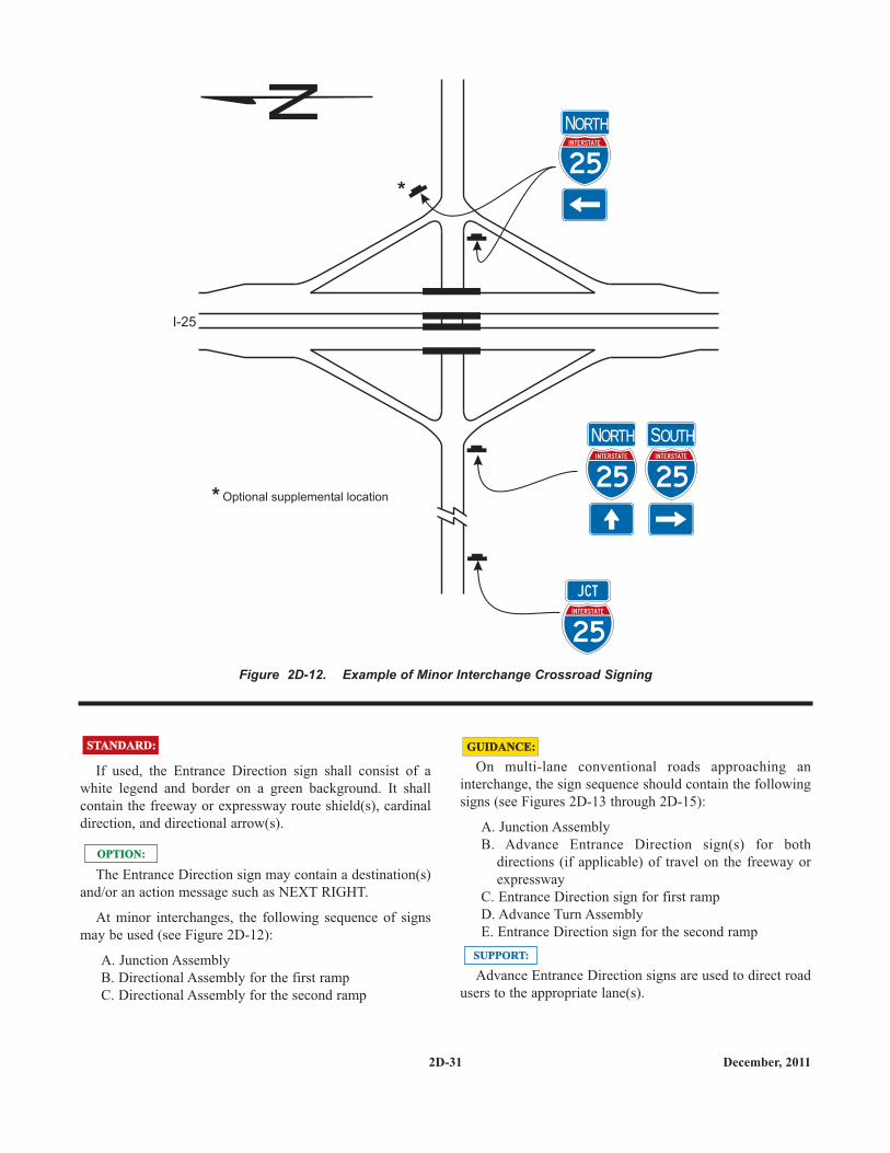
2D-31 December, 2011
If used, the Entrance Direction sign shall consist of awhite legend and border on a green background. It shallcontain the freeway or expressway route shield(s), cardinaldirection, and directional arrow(s).
The Entrance Direction sign may contain a destination(s)and/or an action message such as NEXT RIGHT.
At minor interchanges, the following sequence of signsmay be used (see Figure 2D-12):
A. Junction Assembly B. Directional Assembly for the first ramp C. Directional Assembly for the second ramp
STANDARD:STANDARD:
OPTION:OPTION:
On multi-lane conventional roads approaching aninterchange, the sign sequence should contain the followingsigns (see Figures 2D-13 through 2D-15):
A. Junction Assembly B. Advance Entrance Direction sign(s) for both
directions (if applicable) of travel on the freeway orexpressway
C. Entrance Direction sign for first ramp D. Advance Turn Assembly E. Entrance Direction sign for the second ramp
Advance Entrance Direction signs are used to direct roadusers to the appropriate lane(s).
GUIDANCE:GUIDANCE:
SUPPORT:SUPPORT:
Figure 2D-12. Example of Minor Interchange Crossroad Signing
I-25
NN O RTHO RTH
NN O RTHO RTH SS O UTHO UTH
*
* Optional supplemental location

2D-32December, 2011
Figure 2D-13. Example of Multi-Lane Crossroad Signing for a Diamond Interchange
OVERHEAD
OR
OR
OR
OR
I-64
WWESTEST
WWESTEST
6 4
64 64
64
C a l e b a u g h
64WES T
C a l e b a u g h
64WES T
A n d e rs o n
64E AS T A n d e rs o n
64E AS T
OVERHEAD
C a l e b a u g h
64
WES T
N E XT L E FT
C a l e b a u g h
64
WES T
K E E P L E FT
A n d e rs o n
64
K E E P R I G H T
64
WES T
K E E PL E FT
K E E PR I G H T
E AS T

2D-33 December, 2011
Figure 2D-14. Example of Multi-Lane Crossroad Signing for a Partial Cloverleaf Interchange
OR
I-91
OVERHEAD
G u s t a f s o n
N O R T H
N E XT L E FT
9 1
G u s t a f s o nS E C O N D L E FT
N O R T H
9 1
C u l v e r
9 1S O U T H
OR
OR
OR
D13-3
D13-3
D13-3a
D13-3a
OR
OR
G u s t a f s o n
N O R T H
9 1
ENTRAN CE
FR E EWAY
ENTRAN CE
FR E EWAY
ENTRAN CE
FR E EWAY
ENTRAN CE
FR E EWAY
9 1
NN O RTHO RTH
9 1
9 1
9 1
NN O RTHO RTH
SS O UTHO UTH
G u s t a f s o n
N O R T H
9 1
C u l v e r
9 1S O U T H
C u l v e r
9 1S O U T H
N E XT L E FT
9 1

2D-34December, 2011
Figure 2D-15. Examples of Multi-Lane Crossroad Signing for a Cloverleaf Interchange
locate on or in front of bridgeif freeway goes over crossroad
OVERHEAD
OR
OR
I-57
N O R T H
N O R T H
N O R T H
S O U T H
N O R T H
S O U T H
B a rt e l t
B a rt e l t
B a rt e l t
U l v e n
B a rt e l t
U l v e n
S O U T H
U l v e n
M I L EE X I T 1 4
M I L EE X I T S 1 4
S E C O N D R I G H T
N E XT R I G H T

2D-35 December, 2011
intervening intersection on the same side of the approachroadway and where signing for only the ramp might causeconfusion to road users.
If used, the post-mounted Advance Entrance Directiondiagrammatic guide sign shall display only the twosuccessive turns from the same side of the roadway, one ofwhich shall be the entrance ramp. The post-mountedAdvance Entrance Direction sign shall depict only thesuccessive turns and shall not depict lane use with lane lines,multiple arrow shafts for the approach roadway, actionmessages, or other representations.
Section 2D.46 contains information regarding the use of aDirectional assembly or a FREEWAY ENTRANCE sign tomark the entrance to a freeway or expressway at the farcorner of an intersection.
STANDARD:STANDARD:
SUPPORT:SUPPORT:
The Advance Entrance Direction sign shall consist of awhite legend and border on a green background. It shallcontain the freeway or expressway route shield(s) andcardinal direction(s).
The Advance Entrance Direction sign may have destina-tions, directional arrows, and/or an action message such asKEEP LEFT, NEXT LEFT, or SECOND RIGHT. Signs inthis sequence may be mounted overhead to improvevisibility as shown in Figures 2D-13 through 2D-15.
A post-mounted Advance Entrance Direction diagram-matic guide sign (see Figure 2D-16), within the sequence ofapproach guide signing described in Paragraphs 3, 6, and 7,might be helpful in depicting the location of a freeway orexpressway entrance ramp that is in close proximity to an
STANDARD:STANDARD:
OPTION:OPTION:
SUPPORT:SUPPORT:
Figure 2D-16 Example of Crossroad Signing for an Entrance Ramp with a Nearby Frontage Road
1 0
EE ASTAST
1 0
E A S TWE S T
2 N D R I G H TF ro n t a g e
R o a d
1 0
1 0
E A S T E A S T
1 0
Location for directionalassembly or alternatelocation for guide signdepending on distancebetween ramp and frontageroad intersections.
See Figures 2D-11 through2D-15 for additional signingon crossroad approaches.
*
*
I-10
FRONTAGE ROAD
OR
OR

2D-36December, 2011
2D.46 Freeway Entrance Signs(D13-3 and D13-3a)
FREEWAY ENTRANCE (D13-3) signs or FREEWAYENTRANCE with downward pointing diagonal arrow(D13-3a) signs may be used on entrance ramps near thecrossroad to inform road users of the freeway or expresswayentrance, as appropriate.
The D13-3 and D13-3a signs may display an alternatelegend in place of FREEWAY, such as EXPRESSWAY orPARKWAY, as appropriate, or may display the name of anunnumbered highway.
A Directional assembly (see Section 2D.32) with adownward pointing diagonal arrow auxiliary (M6-2a) sign(see Section 2D.28) may be used at the far left-hand cornerof an intersection with a freeway or expressway entranceramp as an alternative to the D13-3a sign, facing left-turningtraffic on the conventional road approach to indicate theimmediate point of entry to the freeway or expressway anddistinguish the entrance ramp from an adjoining exit rampterminal at the same intersection with the conventional road(see Figure 2D-14). A similar Directional assembly may beused at the far right-hand corner of an intersection with afreeway or expressway entrance ramp where the entranceramp and a crossroad or side road follow one another inclose succession on the conventional road approach and thepoint of entry to the freeway or expressway might bedifficult for the road user to distinguish from the crossroador side road on the conventional road approach (see Figure2D-14).
Section 2B.41 contains information regarding the use ofregulatory signs to deter wrong-way movements at intersec-tions of freeway or expressway ramps with conventionalroads, and in the area where entrance ramps intersect withthe mainline lanes.
ENTRAN CE
FR E EWAY
EN TRAN CE
FR E EWAY
D13-3aD13-3
OPTION:OPTION:
SUPPORT:SUPPORT:
2D.47 Parking Area Guide Sign (D4-1)
The Parking Area (D4-1) guide sign may be used to showthe direction to a nearby public parking area or parkingfacility.
If used, the Parking Area (D4-1) guide sign shall be ahorizontal rectangle with a standard size of 30 x 24 inches,or with a smaller size of 18 x 15 inches for minor, low-speedstreets. It shall carry the word PARKING, with the letter Pfive times the height of the remaining letters, and adirectional arrow. The legend and border shall be green on aretroreflectorized white background.
If used, the Parking Area guide sign should be installed onmajor thoroughfares at the nearest point of access to theparking facility and where it can advise drivers of a place topark. The sign should not be used more than four blocksfrom the parking area.
2D.48 PARK - RIDE Sign (D4-2)
PARK - RIDE (D4-2) signs may be used to direct roadusers to park - ride facilities.
The signs shall contain the word message PARK - RIDEand direction information (arrow or word message).
PA R K I N G
D4-1
OPTION:OPTION:
STANDARD:STANDARD:
GUIDANCE:GUIDANCE:
OPTION:OPTION:
PAR K
R I D E
-
D4-2
STANDARD:STANDARD:

2D-37 February, 2018
PARK - RIDE signs may contain the local transitpictograph and/or carpool symbol on the sign.
If used, the local transit pictograph and/or carpool symbolshall be located in the top part of the sign above the messagePARK - RIDE. In no case shall the vertical dimension of thelocal transit pictograph and/or carpool symbol exceed 18inches.
If the function of the parking facility is to provide parkingfor persons using public transportation, the local transitpictograph should be used on the guide sign. If the functionof the parking facility is to serve carpool riders, the carpoolsymbol should be used on the guide sign. If the parkingfacility serves both functions, both the pictograph andcarpool symbol should be used.
These signs shall have a retroreflective white legend andborder on a rectangular green background. The carpoolsymbol shall be as shown for the D4-2 sign. The color of thelocal transit pictograph shall be selected by the local transitauthority.
To increase the target value and contrast of the localtransit pictograph, and to allow the local transit pictographto retain its distinctive color and shape, the pictograph maybe included within a white border or placed on a whitebackground.
2D.49 Weigh Station Signing (D8 Series)
The general concept for Weigh Station signing is similarto Rest Area signing (see Section 2I.05) because in bothcases traffic using either area remains within the right-of-way.
The standard installation for Weigh Station signing shallinclude three basic signs:
A. Advance sign (D8-1);B. Exit Direction sign (D8-2), andC. Gore sign (D8-3).
Example locations of these signs are shown in Figure 2D-17.
OPTION:OPTION:
STANDARD:STANDARD:
GUIDANCE:GUIDANCE:
STANDARD:STANDARD:
OPTION:OPTION:
SUPPORT:SUPPORT:
STANDARD:STANDARD:
SUPPORT:SUPPORT:
Where State law requires a regulatory sign (R13-X1) inadvance of the Weigh Station, a fourth sign (see Section2B.60) may be located following the Advance sign.
The Exit Direction sign (D8-2) or the Advance sign (D8-1) should display, either within the sign border or on a sup-plemental plaque or sign panel, the changeable messageOPEN or CLOSED.
2D.50 Community Wayfinding Signs
Community wayfinding guide signs are part of acoordinated and continuous system of signs that directtourists and other road users to key civic, cultural, visitor,and recreational attractions and other destinations within acity or a local urbanized or downtown area.
Community wayfinding guide signs are a type ofdestination guide sign for conventional roads with acommon color and/or identification enhancement marker fordestinations within an overall wayfinding guide sign plan foran area.
Figures 2D-18 through 2D-20 illustrate various examplesof the design and application of community wayfindingguide signs.
The use of community wayfinding guide signs shall belimited to conventional roads. Community wayfinding guidesigns shall not be installed on freeway or expresswaymainlines or ramps. Direction to community wayfindingdestinations from a freeway or expressway shall be limitedto the use of a Supplemental Guide sign (see Section 2E.35)on the mainline and a Destination sign (see Section 2D.37)on the ramp to direct road users to the area or areas withinwhich community wayfinding guide signs are used. Theindividual wayfinding destinations shall not be displayed onthe Supplemental Guide and Destination signs except wherethe destinations are in accordance with the State or agencypolicy on Supplemental Guide signs.
Community wayfinding guide signs shall not be used toprovide direction to primary destinations or highway routesor streets. Destination or other guide signs shall be used forthis purpose as described elsewhere in this Chapter and shallhave priority over any community wayfinding sign inplacement, prominence, and conspicuity.
Because regulatory, warning, and other guide signs havea higher priority, community wayfinding guide signs shallnot be installed where adequate spacing cannot be provided
OPTION:OPTION:
GUIDANCE:GUIDANCE:
SUPPORT:SUPPORT:
STANDARD:STANDARD:
MN
Rev
. 6

2D-38February, 2018
4000 feetApproximate
800 feetMinimum
D8-3
D8-2
D8-1
R13-X1
1 mile
S TAT I O N
N E XT R I G H T
I G HS TAT I O N
1 M I L E
Direction of travel
Legend
T R U C K & CO M B I N AT I O N SO V E R 1 0 ,0 0 0 L B SM U S T E N T E RW E I G H S TAT I O NW H E N F LA S H I N G
Figure 2D-17. Example of Weigh Station SigningMN
Rev
. 6

2D-39 July, 2013
between the community wayfinding guide sign and otherhigher priority signs. Community wayfinding guide signsshall not be installed in a position where they would obscurethe road users' view of other traffic control devices.
Community wayfinding guide signs shall not be mountedoverhead.
If used, a community wayfinding guide sign systemshould be established on a local municipal or equivalentjurisdictional level or for an urbanized area of adjoiningmunicipalities or equivalent that form an identifiablegeographic entity that is conducive to a cohesive andcontinuous system of signs. Community wayfinding guidesigns should not be used on a regional or statewide basiswhere infrequent or sparse placement does not contribute toa continuous or coordinated system of signing that is readilyidentifiable as such to the road user. In such cases,Destination or other guide signs detailed in this Chaptershould be used to direct road users to an identifiable area inwhich the type of eligible destination described in Paragraphone of the first Support is located.
The specific provisions of this Section regarding thedesign of community wayfinding sign legends apply tovehicular community wayfinding signs and do not apply tothose signs that are intended only to provide information or
GUIDANCE:GUIDANCE:
SUPPORT:SUPPORT:
direction to pedestrians or other users of a sidewalk orroadside area.
Because pedestrian wayfinding signs typically usesmaller legends that are inadequately sized for viewing byvehicular traffic and because they can provide direction topedestrians that might conflict with that appropriate forvehicular traffic, wayfinding signs designed for andintended to provide direction to pedestrians or other users ofa sidewalk or other roadside area should be located tominimize their conspicuity to vehicular traffic. Such signsshould be located as far as practical from the street, such asat the far edge of the sidewalk. Where locating such signsfarther from the roadway is not practical, the pedestrianwayfinding signs should have their conspicuity to vehiculartraffic minimized by employing one or a combination of thefollowing methods:
A.Locating signs away from intersections where high-priority traffic control devices are present.
B. Facing the pedestrian message toward the sidewalkand away from the street.
C. Cantilevering the sign over the sidewalk if thepedestrian wayfinding sign is mounted at a heightconsistent with vehicular traffic signs, removing thepedestrian wayfinding signs from the line of sight in asequence of vehicular signs.
GUIDANCE:GUIDANCE:
Figure 2D-18 Examples of Community Wayfinding Guide Signs
H
AMILTO
N
Rog e rs Locom ot i ve
Ove r l oo k Pa rkV i s i t o r Ce n te r
C i ty H a l l
C om m u n i tyC e n te r
SOUTH HILL
Re nw i c k D i st r i c ts
C o l l e g etow n
So u t h H i l l
La ke f ro n t
So u t h H i l l
La ke f ro n t
A - Community Wayfinding Guide Signs with Enhancement Markers
B - Destination Guide Signs for Color-Coded Community Wayfinding System
H
AMILTO
N
H i sto r i c D i st r i c tG rea t Fa l l s
MN
Rev
. 2

2D-40December, 2011
To further minimize their conspicuity to vehicular trafficduring nighttime conditions, pedestrian wayfinding signsshould not be retroreflective.
Color coding is sometimes used on communitywayfinding guide signs to help road users distinguishbetween multiple potentially confusing traffic generator des-tinations located in different neighborhoods or subareaswithin a community or area.
SUPPORT:SUPPORT:
At the boundaries of the geographical area within whichcommunity wayfinding guide signing is used, an informa-tional guide sign (see Figures 2D-18 and 2D-20) may beposted to inform road users about the presence ofwayfinding signing and to identify the meanings of thevarious color codes or pictographs that are being used.
OPTION:OPTION:
Figure 2D-19 Example of a Community Wayfinding Guide Sign SystemShowing Direction from a Freeway or Expressway
H
AMILTO
N
Rog e rs Locom ot i ve
Ove r l oo k Pa rkV i s i t o r Ce n te r
C i ty H a l l
H
AMILTO
N
P h oe n i x M i l l
Ove r l oo k Pa rkV i s i t o r Ce n te r
H
AMILTO
N
Ove r l oo k Pa rkV i s i t o r Ce n te r
H
AMILTO
N
V i s i t o r Ce n te r l
P h oe n i x M i l lOve r l oo k Pa rk
HA
MILTO
N
PAR K I N G
Rog e rsLocom ot i ve
GREAT FALLS
OVERLOOK
PARK
VISITOR
CENTER
ROGERS
LOCOMOTIVE
PHOENIX
MILL
CITY
HALL
DESTINATION GUIDE SIGN
SUPPLEMENTAL GUIDE SIGN
H
AMILTO
N
H i sto r i c D i st r i c tG rea t Fa l l s
G rea t Fa l l s
H i s t o r i c D i st r i c t
G re a t Fa l l s
H i s t o r i c D i s t r i c t
5 7EX I T

2D-41 December, 2011
These informational guide signs shall have a white legendand border on a green background and shall have a designsimilar to that illustrated in Figures 2D-1 and 2D-18 andshall be consistent with the basic design principles for guidesigns. These informational guide signs shall not be installedon freeway or expressway mainlines or ramps.
The color coding or a pictograph of the identificationenhancement markers of the community wayfinding guidesigning system shall be included on the informational guidesign posted at the boundary of the community wayfindingguide signing area. The color coding or pictographs shall
STANDARD:STANDARD:apply to a specific, identifiable neighborhood or geographi-cal subarea within the overall area covered by thecommunity wayfinding guide signing. Color coding orpictographs shall not be used to distinguish betweendifferent types of destinations that are within the samedesignated neighborhood or subarea. The color coding shallbe accomplished by the use of different colored square orrectangular panels on the face of the informational guidesign, each positioned to the left of the neighborhood ornamed geographic area to which the color-coding panelapplies. The height of the colored square or rectangularpanels shall not exceed two times the height of the upper-case letters of the principal legend on the sign.
Figure 2D-20 Example of a Color-Coded Community Wayfinding Guide Sign System
Re nw i c k D i st r i c ts
C o l l e g etow n
So u t h H i l l
La ke f ro n t
VISITORCENTER
ART MUSEUM
COLLEGETOWN
PERFORMINGARTS CENTER
RENWICKCORPORATE BOUNDARY
Color coding panels are used onlywhen optional destination guidesign is used at wayfinding boundary
OPTIONAL DESTINATIONGUIDE SIGN AT WAYFINDINGBOUNDARY (see Section 2D.3)
DESTINATION GUIDE SIGN
GENERAL INFORMATIONSIGN (see Section 2H.5)
LAKEFRONTSTEWART
PARKDOWNTOWNSOUTH HILL
COMMUNITYCENTER
CLINTONHOUSE
PARKING
DESTINATION GUIDE SIGN
*
*
*
So u t h H i l l
La ke f ro n t
C o l l e g etow nPe rfo rm i n gA rts Ce n te r
A rt M u se u m
Collegetown
C l i n t o nH o u se
PAR K I N G
Downtown
Com m u n i tyC e n te r
South Hill
Ove r l oo k
C ay u g aV i s i t o r Ce n te rStewa rt Pa rk
R e nw i c kENTER I N G
Lakefront
Horizontal lines of a color that contrasts with the signbackground color should be used to separate groups of des-tinations by direction from each other.
The basic requirement for all highway signs, includingcommunity wayfinding signs, is that they be legible to thosefor whom they are intended and that they be understandablein time to permit a proper response. Section 2A.6 containsadditional information on the design of signs, includingdesirable attributes of effective designs.
Word messages should be as brief as practical and thelettering should be large enough to provide the necessarylegibility distance.
The minimum specific ratio of letter height to legibilitydistance shall comply with the provisions of Section 2A.13.The size of lettering used for destination and directionallegends on community wayfinding signs shall comply withthe provisions of minimum letter heights as provided inSection 2D.6.
Interline and edge spacing shall comply with theprovisions of Section 2D.6.
Except as provided in the following Option, the letteringstyle used for destination and directional legends oncommunity wayfinding guide signs shall comply with theprovisions of Section 2D.5.
The lettering for destinations on community wayfindingguide signs shall be a combination of lower-case letters withinitial upper-case letters (see Section 2D.5). All other wordmessages on community wayfinding guide signs shall be inall upper-case letters.
A lettering style other than the Standard Alphabetsprovided in the "Standard Highway Signs and Markings"book may be used on community wayfinding guide signs ifan engineering study determines that the legibility andrecognition values for the chosen lettering style meet orexceed the values for the Standard Alphabets for the samelegend height and stroke width.
Except for signs that are intended to be viewed only bypedestrians, bicyclists stopped out of the flow of traffic, oroccupants of parked vehicles, Internet and e-mail addresses,including domain names and uniform resource locators(URL), shall not be displayed on any communitywayfinding guide sign or sign assembly.
SUPPORT:SUPPORT:
GUIDANCE:GUIDANCE:
STANDARD:STANDARD:
OPTION:OPTION:
STANDARD:STANDARD:
2D-42December, 2011
The different colored square or rectangular panels mayinclude either a black or a white (whichever provides thebetter contrast with the color of the panel) letter, numeral, orother appropriate designation to identify the destination.
Except for the informational guide sign posted at theboundary of the wayfinding guide sign area, communitywayfinding guide signs may use background colors otherthan green in order to provide a color identification for thewayfinding destinations by geographical area within theoverall wayfinding guide signing system. Color-codedcommunity wayfinding guide signs may be used with orwithout the boundary informational guide sign displayingcorresponding color-coding panels described in the previoustwo Options and the previous Standard. Except as providedin paragraphs one and two of the following Standard, inaddition to the colors that are approved in this Manual foruse on official traffic control signs (see Section 2A.10),other background colors may also be used for the colorcoding of community wayfinding guide signs.
The standard colors of red, orange, yellow, purple, or thefluorescent versions thereof, fluorescent yellow-green, andfluorescent pink shall not be used as background colors forcommunity wayfinding guide signs, in order to minimizepossible confusion with critical, higher-priority regulatoryand warning sign color meanings readily understood by roadusers.
The minimum luminance ratio of legend to backgroundfor community wayfinding guide signs shall be 3:1.
All messages, borders, legends, and backgrounds ofcommunity wayfinding guide signs and any identificationenhancement markers shall be retroreflective (see Sections2A.7 and 2A.8).
Community wayfinding guide signs, exclusive of anyidentification enhancement marker used, should berectangular in shape. Simplicity and uniformity in design,position, and application as described in Section 2A.6 areimportant and should be incorporated into the communitywayfinding guide sign design and location plans for the area.
Community wayfinding guide signs should be limited tothree destinations per sign (see Section 2D.7).
Abbreviations (see Section 1A.15) should be kept to aminimum, and should include only those that are commonlyrecognized and understood.
OPTION:OPTION:
STANDARD:STANDARD:
GUIDANCE:GUIDANCE:

The arrow location and priority order of destinations shallfollow the provisions described in Sections 2D.8 and 2D.37.Arrows shall be of the designs provided in Section 2D.8.
Pictographs (see definition in Section 1A.13) may be usedon community wayfinding guide signs.
If a pictograph is used, its height shall not exceed twotimes the height of the upper-case letters of the principallegend on the sign.
Except for pictographs, symbols that are not approved inthis Manual for use on guide signs shall not be used oncommunity wayfinding guide signs.
Business logos, commercial graphics, or other forms ofadvertising (see Section 1A.1) shall not be used oncommunity wayfinding guide signs or sign assemblies.
Other graphics that specifically identify the wayfindingsystem, including identification enhancement markers, maybe used on the overall sign assembly and sign supports.
An enhancement marker consists of a shape, color, and/orpictograph that is used as a visual identifier for thecommunity wayfinding guide signing system for an area.Figure 2D-18 shows examples of identificationenhancement marker designs that can be used withcommunity wayfinding guide signs.
An identification enhancement marker may be used in acommunity wayfinding guide sign assembly, or may beincorporated into the overall design of a communitywayfinding guide sign, as a means of visually identifying thesign as part of an overall system of community wayfindingsigns and destinations.
The sizes and shapes of identification enhancementmarkers shall be smaller than the community wayfindingguide signs themselves. Identification enhancement markersshall not be designed to have an appearance that could bemistaken by road users as being a traffic control device.
The area of the identification enhancement marker shouldnot exceed 1/5 of the area of the community wayfindingguide sign with which it is mounted in the same signassembly.
OPTION:OPTION:
STANDARD:STANDARD:
OPTION:OPTION:
SUPPORT:SUPPORT:
OPTION:OPTION:
STANDARD:STANDARD:
GUIDANCE:GUIDANCE:
2D.51 Truck, Passing, or Climbing LaneSigns (D17-1 and D17-2)
If an extra lane has been provided for trucks and otherslow-moving traffic, a NEXT TRUCK LANE XX MILES(D17-1) sign and/or a TRUCK LANE XX MILES (D17-2)sign should be installed in advance of the lane.
Alternative legends such as PASSING LANE orCLIMBING LANE may be used instead of TRUCK LANE.
Section 2B.31 contains information regarding regulatorysigns for these types of lanes.
2D.52 Slow Vehicle Turn-Out Sign (D17-7)
If a slow vehicle turn-out area has been provided forslow-moving traffic, a SLOW VEHICLE TURN-OUT XXMILES (D17-7) sign should be installed in advance of theturn-out area.
Section 2B.35 contains information regarding regulatorysigns for slow vehicle turn-out areas.
TR U CK
LAN E
M I L E1 2/
N EXT
TR U CK
LAN E
M I L E S2
D17-2D17-1
GUIDANCE:GUIDANCE:
OPTION:OPTION:
S LOW VEH I C L E
TU R N -O UT
M I L E1 2/
D17-7
GUIDANCE:GUIDANCE:
OPTION:OPTION:
2D-43 December, 2011

2D.53 Signing of Named Highways
Guide signs may contain street or highway names if thepurpose is to enhance driver communication and guidance;however, they are to be considered as supplementalinformation to route numbers.
Highway names shall not replace official numeral desig-nations.
Memorial names (see Section 2M.10) shall not appear onsupplemental signs or on any other information sign on oralong the highway or its intersecting routes.
The use of route signs shall be restricted to signs officiallyused for guidance of traffic in accordance with this Manualand the "Purpose and Policy" statement of the AmericanAssociation of State Highway and Transportation Officialsthat applies to Interstate and U.S. numbered routes (see Pagei for AASHTO's address).
Unnumbered routes having major importance to properguidance of traffic may be signed if carried out inaccordance with the aforementioned policies. Forunnumbered highways, a name to enhance route guidancemay be used where the name is applied consistentlythroughout its length.
Only one name should be used to identify any highway,whether numbered or unnumbered.
2D.54 Crossover Signs (D13-1 and D13-2)
Crossover signs may be installed on divided highways toidentify median openings not otherwise identified bywarning or other guide signs.
A CROSSOVER (D13-1) sign shall not be used toidentify a median opening that is permitted to be used onlyby official or authorized vehicles. If used, the sign shall be ahorizontal rectangle of appropriate size to carry the wordCROSSOVER and a horizontal directional arrow. TheCROSSOVER sign shall have a white legend and border ona green background.
OPTION:OPTION:
STANDARD:STANDARD:
OPTION:OPTION:
GUIDANCE:GUIDANCE:
CROSSOVER
M I L E14
CROSSOVER
D13-2D13-1
OPTION:OPTION:
STANDARD:STANDARD:
If used, the CROSSOVER sign should be installedimmediately beyond the median opening, either on the right-hand side of the roadway or in the median.
The Advance Crossover (D13-2) sign may be installed inadvance of the CROSSOVER sign to provide advancenotice of the crossover.
If used, the Advance Crossover sign shall be a horizontalrectangle of appropriate size to carry the wordCROSSOVER and the distance to the median opening. Thesign shall have white legend and border on a greenbackground.
The distance displayed on the Advance Crossover signshould be 1 MILE, 1/2 MILE, or 1/4 MILE, unless unusualconditions require some other distance. If used, the signshould be installed either on the right-hand side of theroadway or in the median at approximately the distancedisplayed on the sign.
GUIDANCE:GUIDANCE:
OPTION:OPTION:
STANDARD:STANDARD:
GUIDANCE:GUIDANCE:
2D-44December, 2011

2D.55 National Scenic Byways Signs(D6-4, D6-4a)
Certain roads have been designated by the U.S. Secretaryof Transportation as National Scenic Byways or All-American Roads based on their archeological, cultural,historic, natural, recreational, or scenic qualities.
State and local highway agencies may install the NationalScenic Byways (D6-4 or D6-4a) signs at entrance points toa route that has been recognized by the U.S. Secretary ofTransportation as a National Scenic Byway or an All-American Road. The D6-4 or D6-4a sign may be installed onroute sign assemblies or as part of larger roadside structures.National Scenic Byways signs may also be installed atperiodic intervals along the designated route and shall beinstalled at intersections where the designated route turns orfollows a different numbered highway. At locations whereroadside features have been developed to enhance thetraveler's experience such as rest areas, historic sites, inter-pretive facilities, or scenic overlooks, the National ScenicByways sign may be placed on the associated sign assemblyto inform travelers that the site contributes to the bywaytravel experience.
When a National Scenic Byways sign is installed on aNational Scenic Byway or an All-American Road, thedesign shown for the D6-4 or D6-4a sign shall be used. Use
AMERICA’S BYWAYS
AMERICA’S
BYWAYS
D6-4aD6-4
38 38
N O RTH N O RTH
National Scenic Bywayroute sign assembly
SUPPORT:SUPPORT:
OPTION:OPTION:
STANDARD:STANDARD:
of this design shall be limited to routes that have beendesignated as a National Scenic Byway or All-AmericanRoad by the U.S. Secretary of Transportation.If used, theD6-4 or D6-4a sign shall be placed such that the roadwayroute signs have primary visibility for the road user.
2D-45 December, 2011