parel carshed training
TRANSCRIPT
PROJECT REPORT ON
STUDY OF DIESEL ELECTRIC
LOCOMOTIVE CONDUCTED AT
CENTRAL RAILWAY WORKSHOP,PAREL.
SUBMITTED BY:
1. AJINKYA POPAT GORDE
2. VAIBHAV VASANT BHOSALE
3. YOBU SUNDER LIVINGSTON
DEPARTMENT OF ELECTRICAL ENGINEERING.SARDAR PATEL COLLEGE OF
ENGINEERING,

ANDHERI, MUMBAI.

SPECIAL THANKS
We are highly obliged to express our deep gratitude towards those who have provided us helping hand throughout the Project work. Firstly we would like to thank The Railway Administration particularly The Chief Workshop Manager Shri B.V.NANDANVAR, who has given us opportunity to carry out our project work otherwise this would have not been possible. For this we are also very much thankful to The Chief instructor Shri Geogy T.T, Basic Training Centre (B.T.C.) because of his great effort we get opportunity to be here. We are thankful to our Project incharge Shri Venkat B. Wavdane, The Section Engineer Shri Patange us with his vast experiences in the stage of etl:, Project. We are also thankful to The JE-I Shri Thakur,clearing the mechanical terms involved in the project.also express thanks to Shri Surve giving us your valuable Co-operation even in the busy working period. We all remain thankful to you all Sirs.

PAREL CARSHED TRAINING(9/12/2014 to 8/1/2015)
BRIEF HISTORY OF LOCO WORKSHOP/PAREL
Loco Workshop, Parel was set up by GIPR as a Steam Loco Shed in 1879. Later,POH of Steam Loco was started there. From 1974-75 onwards, POH of DieselLocomotives was started at Parel. It is one of the largest and oldest repair workshops on the Indian Railways with diversified repair/manufacturing activities.
Presently, Parel workshop is doing
POH of diesel locomotives, manufacturing of WDG3A, WDS6, NG loco of NDM class for Neral-Matheran and ZDM3 locomotives for Kalka-Shimla, POH of 140T Diesel Hydraulic crane, POH of tower wagons and MLR of coaches.
This workshop is ISO 9001 certified. This is the only workshop other than DLW and CLW, which undertakes manufacture of diesel locomotives.
CENTRAL RAILWAY - PARELVITAL STATISTICS1. Sanctioned Strength 53012. On Roll Strength 46833. No. of Officers 224. No. of Supervisors 6225. Total Area 19 acres6. Covered Area 8.1251acres7. Township Area 47 acres8. Power Consumption 549220 units/month9. Water Consumption 22770 KL/month10. Annual Budget Rs.196 Cr.

Different Electrical sections in the Parel carshed:
1. Locomotive Wiring2. Panels and Relays3. Traction motor4. Traction Generators5. Electrical Train Lighting
1) Locomotive Wiring:
The major works undertaken under the locomotive wiring section is the Maintenance and Electrical wiring in the Diesel Locomotive. This section looks after the Wiring of all the electrical equipments in the diesel locomotive. This section looks after the wiring of the electrical equipments and electronic devices and sensor s in the loco e.g. Traction motors, generators batteries,auxillary generator and exciter etc.
Basic Parts of Diesel Engine and its block diagram:
Traction motors:
There are 6 traction motor in a Diesel engine. The DC series motors are used in Low HP engines while in High HP engines Induction motors are used.
Traction Generator:
The traction Generator is basically a Alternator. A alternator is Three phase Synchronous generator. It has a rotating DC excitation field and a stationary armature winding placed on the stator.Typical rating of a traction generator is 4400 amperes, 1100 volts, and 3100 HP
Exciter:
The exciter is a DC generator and is placed on the same shaft as the Traction or main generator, the exciter field winding is energized using the Auxiliary supply voltage. A controller regulates the amount of current flowing through the exciter field winding thus controlling the DC field excitation of Main generator and thus controlling the output of the generator.
Radiator Fan:
The radiator fan is used to limit the temperature of the water used to cool down the engine. The Fan speed is varied in Three steps as the temperature of the water increases.
Battery Section:
The engine has a battery section which has eight batteries each of eight volts, thus the Total battery supply is of 64 V when connected in series. The battery supply is used to start the fuel pump motor (FPM) and the crank shaft motor in order to start the engine.
Fuel pump Motor:

This motor is actuated to fill the Diesel engine with fuel before it is cranked.
Pre-Loop motor:
This motor is actuated for one minute (60 second) before cranking to lubricate all the engine components with oil in order to reduce friction and prevent damage.
Power circuit:
The power circuit is the basic block diagram of the Electrical power system it consist of the interconnections of the Main generator and the exciter and the auxiliary generator.
• Three phase variable frequency, variable voltage output of TA is fed to Alternator Mounted Rectifier
• Rectified DC output of rectifier is fed to 6 DC series motors • During starting all traction motors are connected in 6P 100% FF
combination • As the transition takes above specified loco track speed(50.0 KPH)
a portion of series field CURRENT is by passed by field shunting contactors(FS1, FS2, FS3, FS4, FS5 & FS6) & field shunting resistors (FSR1, FSR2, FSR3, FSR4, FSR5 & FSR6) and all the six traction motors get connected in 6P 49% FF combination
• Electro pneumatic contactors are used in series of each motor for making/breaking of motor circuit.
Cranking and Transition process in Diesel Engine:

While starting (Cranking) the engine, first the Fuel pump motor is started so that the fuel is filled in the engine from the fuel tank, along
with the fuel pump motor the Pre loop motor is also operated to lubricate or circulate the oil in the entire diesel engine to reduce friction for one minute and then the crank motor (Initially the Auxiliary and exciter generator act as crank motor and start the engine)is operated by the
Driver, As a result the diesel engine Shaft starts rotating. after this with the help of contactors the Auxiliary motor and exciter motor act as

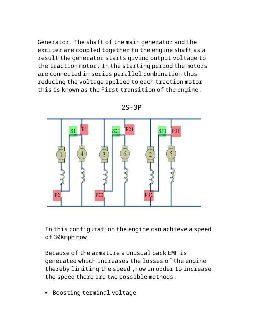
Generator. The shaft of the main generator and the exciter are coupled together to the engine shaft as a result the generator starts giving output voltage to the traction motor. In the starting period the motors are connected in series parallel combination thus reducing the voltage applied to each traction motor this is known as the First transition of the engine.
2S-3P

In this configuration the engine can achieve a speed of 30Kmph now
Because of the armature a Unusual back EMF is generated which increases the losses of the engine thereby limiting the speed ,now in order to increase the speed there are two possible methods.
Boosting terminal voltage Bypassing field current
So in order to increase the speed a Shunt resistance is connected across the field thereby by-passing the current through the field winding and increasing the speed to 50Kmph.
Battery charging circuit:
2)_Panels and Relays:
This section consists of all the Sensor and Generator field contactors and the miniature circuit breaker used in the diesel loco. This section supplies all the required electrical components and looks after the availability of the various components in the workshop. The various components available in the section are as follows:
Panels: Excitation control panel: Controls the dc field excitation of the
alternator
Engine control panel: Controls the engine horse power with the help of the governor it varies the fuel rack to control the engine power as per the demand
Voltage regulator panel: Regulates the voltage to 72 v DC for the other equipments in the loco
Transition control panel: Controls the series traction motor contactors.
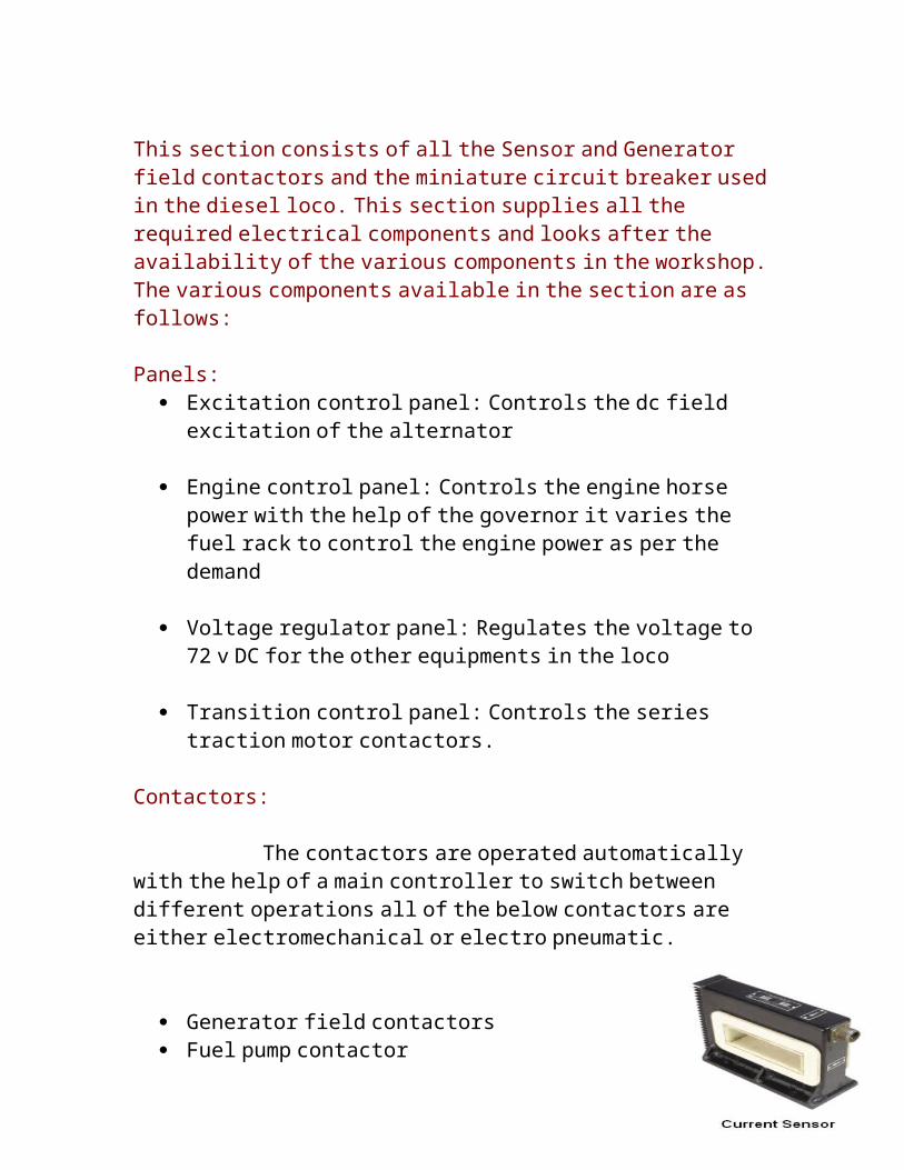
Contactors: The contactors are operated automatically with the help of a main controller to switch between different operations all of the below contactors are either electromechanical or electro pneumatic.
Generator field contactors Fuel pump contactor Cranking contactor Radiator fan contactor Field shunt contactor
SPEED SENSOROther equipments in this section:Sensors:
Current sensor Voltage sensor Water level sensor Speed sensor

Displays: Main display unit Water level indictor Pressure gauges User interface display
Besides this they also have Switches, speed recording system, flashers,LEDs,meters,resistance bank, rectifiers,
Temperature sensor
Voltage sensor
MAIN DISPLAY
3) Traction motor:
The work undertaken in this section is the Maintenance of the Traction motor. In this the traction is completely dismantled and the field coiled and pole are removed and checked for any damaged
This is the major component of the loco. In the old days DC series motors were used as traction motors because of ease of speed and torque control in the earlier days because of lack of electronic advancement it was difficult to use AC motors to drive the loco. But in the modern days due to advent of the electronic devices like thyrsitors and GTO and IGBT’s made the use and control simple as compared to DC motors and even much more efficient thus leading to the use of AC motors as traction motors.
The Ac motors used consists of Non-salient pole rotor squirrel cage construction. When the Ac input is applied to the three phase stator it produces a rotating field which induced a current in the rotor thus a unidirectional torque is produced and the rotor starts rotating. by controlling the frequency of the ac input to the stator the speed of the motor can be controlled.
4) Traction Generators:

Traction generator is a separately excited DC generator but now a days it is replaced by a Alternator . These is located in the generator room . It is connected to the main crank shaft of the diesel engine and is self cooled by a fan . These converts mechanical energy of diesel engine into electrical energy to be supplied to traction motor through switchgear for movement of locomotive . In this section there are various works of maintenance undertaken besides the overhauling of Alternator. It also undertakes the maintenance of the Auxiliary generator and the exciter motor. It also looks after the fuel pump motor the blower motor and the eddy current clutch.
In the old locos Dc generators were used while in the modern locos because of use of electronics, Alternators are used.
TRACTION ALTERNATOR:
BHEL-TA 10102 EV(Bhopal):
RPM VOLT AMP OUTPUT REMARK
1050 1075 1938 2083 KW continious
1050 585 3600 2106 KW 1 hr rating
1050 1105 4400 Maximum
STATOR SALIENT POLE ROTOR
Figure 1

TRACTION GENERATOR:
BHEL-TG 10919 AZ/M (Bhopal):
RPM VOLT AMP OUTPUT REMARK
1100 520 1560 812 KW continuous
1100 256 3170 812 KW 1 hr rating
1100 245 3300 809 KW Maximum
Figure 2 Figure 3
ROTOR
STATORAUXILLARY GENERATOR

It is a gear driven from main generator bull gear 4 pole , shunt wound DC generator, which supplies current for battery charging on locomotives as well as auxillaries such as crank case , relays and lightning circuits . It produces constant voltage irrespective of notches .
EXCITER
On E type loco DC exciter supplies current for excitation of main generator field . Governer speed coil gets the current from tachogenerator . The DC exciter on E type loco is same as auxillary generator .
AXLE GENERATOR
The Axle Generator is also provided on L2 axle and is a single phase permanent 40 poles axle and drive AC generator . There are only 2 wires . These single phase voltage is used for electrical speedometer calibration as well as transition panel .
CRANK CASE EXHAUSTER MOTOR
These motor is located on the left side of the engine above cylinder no. 8 . It gets the current from auxiliary source . It is 2 pole compound wound DC motor , it rotates a blower which is used to exhaust the oil fumes and vapours from the engine crank case and it creates vacuum about 1.1/2” to 2” .
FUEL PUMP MOTOR
This motor is located on the right side of the diesel engine in expressor room it gets the current from auxiliary generator.
5) Electrical Train Lighting:
Types of coaches:
1) CN: This is sleeper type of coach. it`s both sides are open. It has total four doors.

2) GS: This is sitting type of coach. it`s both sides are open. It has total four doors.3) CZ: This is sitting type of coach. it`s both sides are open. It has total six doors. 4) GSLR: it`s both sides are close. It has luggage compartments. It also has two types: a) GSLRD: it is guard second ladies disabled b) GSLR
POH of coaches:
In parel workshop mlr is done. Mlr means mead life rehabilitation. It is done after every 12 year`s.coach must complete 12 or more years for mlr
Working of coaches:
1. When coaches are running then an alternator is connected to the shaft of wheel through belt.
2. Electricity is created through alternator and it is directly utilized for fan tube lights and at same time battery is charging.
3. When coach is not moving then electricity is get from batteries. 110v sockets are taken at different points.
4. ERRU: Electronic regulator and rectifier unit is used to control the voltage of the field.
5. A cylinder is provided for air pressure.
Main components:1. battery: total 18 no of battery are used ,which is connected in series.each battery
has 6.6v,120A rating. Total rating of battery box is 110v,120A.2. ERRC: the speed of train is not constant so to adjust the output voltage constant
excitation of field is changed continuously. It also rectify AC to DC supply.3. Alternator: it generates three phase access power.
Diesel Electric Locomotive with MEP 660: Today diesel locomotives use modern control system based on the MEP 660 micro controllers; the use of micro-controller increases the efficiency accuracy and the reliability of the entire system.

The advantages of this over old system are as follows:
Analog Control system with reactors & magnetic amplifiers.
Digital Control system through Microprocessor.

Setting of parameters through potentiometers
Time consuming due to trial and error method.
Set values changes in service.
Requires periodical calibration of potentiometers and maintenance of cards.
All parameters can be set digitally (No potentiometers).
Does not consume time since one time setting.
Set values does not change.o No periodical calibration and
maintenance is required since no potentiometers.
Lot of sequential interlocks (Mechanical) Nearly 23 relays are used. Require periodical testing &
maintenance in schedule.
All the sequential interlocks are converted in to software logic. (Nearly 60 interlocks)
Only 11 relays are used. Periodical maintenance of
these interlocks and relays is reduced.
Very few fault indications. Hardly 10/15 fault indications
through LED’s to driver.
More than 300 Fault messages are available.
Detailed fault message is displayed to driver on screen

Load stabilization is through RC (resistor capacitor) network.
These capacitors are bulky and electrolytic in nature.
They leakage in service and cause poor stabilization.
Periodical testing and maintenance is required.
Load stabilization is through software. No bulky capacitors.
Stabilization timings does not change.
No periodical checking since no bulky capacitors and resistors.
BIBILOGRAPHY:
1. Diesel locomotive guide: Mr.Wavdane
2. Medha manual
3. Railway manual

4.BHEL manual