para. no. statement to be compliance agree… · para. no. statement to be compliance agree/not...
TRANSCRIPT

6 | P a g e
Category-1: Hot & Ultra Cold Chambers
PARA. NO. STATEMENT TO BE COMPLIANCE AGREE/NOT AGREE
1A: Technical Specifications
1. Basic requirement:
Hot & Ultra Cold Chambers shall be used to carry out condensation free Temperature Cycling, Hot Storage Test, Cold Storage Test at different temperatures which may be fixed or variable within operating temperature limits.
1.1: Basic Technical Requirement
2. Structure and Construction
2.1. Over all construction of the chamber shall be bench type.
2.2. The Structural lay out of chambers shall be as per attached drawings in Appendix-2.
Item
No.
Test Work Space
(W x D x H) mm
Volume
(Liters)
Extreme Operating Temp
Range at Ambient (°C)
Average Transition Rate
from Ambient (°C/minute) Test Heat Load
Control
Accuracy (°C)
Temp
Uniformity (°C)
Qty.
(Nos.)
Passive
Active
High Low Heating Cooling Steel (kg) Watt
A B C D E F G H I J K L
1 850 x 500 x 800 340 175 -70 3 2 5 100 ±1 ±2 2 No.
2 1450 x 750 x 800 870 150 -65 3 2 5 100 ±1 ±2 1 No.
3 1000 x 1000 x 500 500 125 -55 3 3 5 100 ±1 ±2 1 No.
4 800 x 800x 800 512 125 -55 3 3 5 100 ±1 ±2 2 No.
ANNEXURE-1: SPECIFICATIONS CUM COMPLIANCE STATEMENT OF CLIMATIC CHAMBERS UNDER CATEGORY-1

PARA. NO. STATEMENT TO BE COMPLIANCE AGREE/NOT AGREE
7 | P a g e
2.3. External dimensions of each chamber shall be optimized with actual test space. Bigger chamber shall be made in such a way that it may transport
through door having 204 cm Height and 165 cm width.
2.4. All parts of refrigeration system like compressors, condensers etc. shall be fixed below the chamber on a single frame. It must be covered with
detachable panel/cover.
2.5. The chamber shall have double wall type construction with minimum 100 mm insulation (glass wool /puff) thickness to take care of heat loss from
the workspace and avoid condensation / hot spots on exterior wall.
2.6. Insulating / Bakelite sheet shall be used at joining point of inner and outer wall of chamber.
2.7. Chamber Material : Inner and outer wall shall be made out of bright polished / buffed S.S. 304, 20 gauge sheet. Locking handles, hinges etc. can be
MS/Brass with hard chrome plating.
2.8. Inner skeleton of the chamber shall be made from appropriate structural member.
2.9. M.S. section shall be used for support frame work and bench structure.
2.10. Support frame and bench must be painted either powder coating or epoxy paint.
2.11. Support frame and bench must not be visible.
2.12. Joints required for the construction of interior shall be avoided in the bottom or shall be welded.
2.13. Work Space Bottom (excluded from the clear workspace): Bottom of the interior with ~3° slope and condensate draining port so that all
condensate from the Dehumidifying coil shall directly flow to the draining port through collector. Draining port shall be provided at rear section of
bottom.
2.14. Caster Wheels: Four lockable non-metallic heavy duty castor wheels of sufficient weight carrying capacity shall be mounted for easy movement of
the chamber on floor. Six caster wheels shall be used for Item No. 2.
3. Doors: doors with door limit switch
3.1. Door should have made using same material and thickness as of chamber, with limit switch.
3.2. Handle on right side with Positive locking arrangement (preferably with two clamps) and Heavy duty hinges on left side of the door.
3.3. Multilayer Observation Window on doors with illumination and window heater at appropriate location.
3.4. Size of the window shall be decided at the time of pre fabrication discussion.
3.5. Double layer silicon gasket shall be provided for proper sealing of the door with chamber.
3.6. Anti-sagging arrangement for door shall be provided, particularly in close condition.

PARA. NO. STATEMENT TO BE COMPLIANCE AGREE/NOT AGREE
8 | P a g e
4. S.S. shelves
4.1. Two S.S. shelves for keeping Device Under Test ( mass of DUT as in column-H of respective Item ), which can be adjusted throughout the height,
made from S.S. net such that it must not restrict air flow of the chamber.
5. Port Holes:
5.1. Two port holes with plug. Size and location of port hole shall be finalized at the time of pre-fabrication discussion.
5.2. A hand shut-off exhaust valve shall be provided with 5 meter long hose of 1 inch nominal diameter to exhaust evaporated N2 gas to out side the
Lab.
6. Fan Motors and Air Circulation
6.1. Fan motor must be 3 phase induction motor with single joint less long shaft made of S.S. properly balanced to avoid any noise and vibration during
operation.
6.2. SS Axial fan shall be used. Only S.S. Nut / bolt must be used to mount fan on motor shaft.
6.3. Sufficient air circulation shall be provided to achieve specified temperature gradient.
6.4. Air shall be sucked by the fan from the workspace, flown down to bottom and entering to workspace for uniform distribution.
6.5. Arrangement to be done so that maximum air flows over air heater, cooling coil, dehumidification coil and work space bottom.
6.6. There shall be provision for intake of the fresh air and to exhaust hot air with hand shut off valve or similar type arrangement.
6.7. Maintainability: Partition for air circulation shall be designed in such a way that Fan, Heaters, Cooling Coil, De-humidifying coils etc. and
compressors, solenoid valves, expansion valves, oil separators, control panel shall have accessibility from maintenance point of view.
7. Heating System
7.1. S.S. Jacketed Electrical Resistance air heater of sufficient capacity, to take care of specified heating rate with safety margin.
7.2. Heaters in star connection to equally distribute the load, controlled by individual ac to ac solid state relay (SSR), contactor, energy regulator and
over temperature controller.
8. Cooling System
i. Low Temperature: -20° C (Approximately) shall be achieved by direct expansion of High Stage Refrigerant.
ii. Very Low Temperature: Extreme low temperature as in column-E shall be achieved by Cascade Refrigeration System.

PARA. NO. STATEMENT TO BE COMPLIANCE AGREE/NOT AGREE
9 | P a g e
iii. Cooling by LN2: Chamber shall have additional cooling provision through Liquid Nitrogen (LN2). Direct injection method shall be used to achieve
-100 °C through controlled cryogenic solenoid valve.
iv. Dehumidification: Operation of the Dehumidifying coil shall be carried out by using High Stage Compressor.
v. A selector switch shall be provided for cooling mode selection i.e. Low Temp / Very Low Temp / LN2.Mode selection shall be in auto and manual
mode. In auto mode, system shall be selected automatically depending on temperature and in manual mode it shall be selected by operator either by
switch or from HMI screen.
8.1. General Requirements:
8.1.1. Semi-sealed refrigeration compressors shall be used for High stage ( R 404-A) and Low stage (R-23 ) refrigeration systems.
8.1.2. Small cooling fan for compressor shall be provided near to the head of compressor.
8.1.3. Air cooled condenser:
a. Combined Air Cooled Heat Exchanger shall be provided for HS and LS systems. Major part of this heat exchanger shall be used as
condenser of HS System and Partial part shall be used as pre-cooling of LS Vapor.
b. LS vapor shall be pre-cooled to ambient temperature before entering to cascade condenser.
c. Brazed Plate Type cascade condenser shall be used.
d. Intermediate output shall be provided in the HS condenser to By-pass the HS high pressure vapor to suction side.
e. Outlet of LS air cooled condenser shall be used for By-pass of high pressure vapor to either suction side or expansion tank.
8.1.4. Length of the suction line shall be maintained as small as possible.
8.1.5. Vibration eliminators shall be provided for discharge and suction line.
8.1.6. Compressor shall be controlled by a contactor, OLR cum single phase preventer, delay on timer, MCBs etc.
8.1.7. Dual evaporating coil shall be provided. One coil is for direct expansion of HS refrigerant and another for expansion of LS refrigerant.
8.1.8. Oil separator, drier, receiver etc. shall be provided for both the system.
8.2. Achieving Low Temperature:
8.2.1. This mode is selected to achieve temperature up to -20° C by direct expansion of HS refrigerant through Thermostatic expansion valve in the
evaporator.
8.2.2. Temperature shall be controlled by HS main SV.

PARA. NO. STATEMENT TO BE COMPLIANCE AGREE/NOT AGREE
10 | P a g e
8.2.3. Due to any reason discharge pressure is increasing or suction pressure is decreasing shall be corrected as explained in operation &control logic
section. If pressure is not corrected shall switch off the compressor.
8.2.4. LS system and Cryogenic SV shall remain off in this mode.
8.3. Achieving very low temperature:
8.3.1. This mode is selected to achieve temperature up to extreme low as in column-E and lower.
8.3.2. Expansion of HS refrigerant shall occur through thermostatic expansion valve in cascade condenser. In this mode HS main SV shall remain
continuously ON and Cascade SV shall operate as par system requirement.
8.3.3. Low Stage (LS) system shall start only after achieving required low temperature in cascade condenser.
8.3.4. Temperature shall be controlled by LS main SV.
8.3.5. Due to any reason discharge pressure is increasing or suction pressure is decreasing shall be corrected as explained in operation &control logic
section. If pressure is not corrected shall switch off the compressor.
8.3.6. Cryogenic SV shall remain off.
8.4. Achieving – 100° C by LN2:
8.4.1. This is to achieve temperature up to -100° C.
8.4.2. Cryogenic SV (¼ inch size) shall control the LN2 flow to control the temperature.
8.4.3. HS and LS systems shall remain off.
8.4.4. All control logic explained for temperature cycling test shall be applicable to LN2 mode operation also.
9. Dehumidification System:
During temperature cycling, relative humidity is high particularly during raising the temperature after low temperature soak, as condensed moisture on
evaporator starts melting and evaporates. Dehumidification shall be carried out as follows.
9.1. HS refrigeration compressor shall be used for this purpose.
9.2. Two radiator type dehumidifying coils of suitable length shall be provided near bottom of the chamber with solenoid valves operating (from sub-
zero to +35° C) alternatively with programmed interval by ON/OFF timer and through Temperature Programmer TP1 with option for manual
operation.
9.3. Both the dehumidifying coils shall have ~30° slope and at the bottom of the each coil, condensate collector shall be provided so that melted water
shall be drained directly to draining port.

PARA. NO. STATEMENT TO BE COMPLIANCE AGREE/NOT AGREE
11 | P a g e
10. Gas Nitrogen Purging
10.1 Dry Nitrogen purging regulator with flow meter and ¼ inch size needle valve shall be provided which shall be used to purge dry nitrogen manually
as and when required for contamination/condensation free work space.
11. Local Heating System:
11.1. Local heating of the Device Under Test (DUT) to keep its temperature above the Dew Point Temperature of workspace air to avoid condensation on
DUT. Infra Red (IR) or reflective lamps of 250W, 230VAC ( Two on slider at top and one on stand) shall be fixed around DUT to provide local
heating. S. S. mounting arrangement for lamp to allow fixation of lamp in any direction and location as required for the test.
11.2. The lamps shall be switch ON while raising the temperature up to approx. 35° C with the help of the Temperature Programmer TP1 through a
contactor and switchboard.
12. Operator & Electrical Panel with data logging
12.1. Electrical panel
12.1.1. Electrical panel shall accommodate all switch gear items like contactors, over load relays, fuses, MCBs, solid state relays etc. shall be fixed
inside panel , with ferrule numbering, properly wired with relevant standards for wiring, on a thick bakelite sheet. Each active element like
motor, compressor, heater etc. shall be provided with precise over current, short-circuit protection system. Switchgears in panel must be
arranged for easy and safe to work, proper arrangement of fresh air intake ,exhaust fans. Illumination with a switch and proper earth point.
12.2. Operator panel
12.2.1. Operator panel having preprogrammed Integrated HMI + PLC unit (for system operation with all necessary controls like programmer, safety
controller, switches, indicators etc. with all required logics for Programmer, controllers, commands, displays, storage, Historical views,
maintenance parameters, various diagnostics and test modes as explained in this tender document,) Emergency stop pushbutton and Integral
Hour meter with reset.
OR
12.2.2. Discrete devices (Temperature programmer, safety controllers to switching and indications, to perform required safe operation with
necessary indication, with net connectivity for data logging) and Hour meter with reset.
Vendor shall propose both option and shall specify clearly which option is selected and if there is any commercial implication for
either option the same has to be clearly indicated in price bid.
12.3. Technical details and Mode of operations

PARA. NO. STATEMENT TO BE COMPLIANCE AGREE/NOT AGREE
12 | P a g e
12.3.1. System operation in Auto and Manual mode with temperature control accuracy of ±1.0°C with respect to the profile given in Programmer
(temperature profile controller having PT-100 sensor Input and multiple digital outputs to control various subsystem in line with process
requirement) and other controllers. It can store minimum 10 different programs of different temperature cycle (Hot and cold Temperature
cycle) using 50 segments. Required temperature range is as per respective chamber capability.
12.3.2. System shall have Data entry of temperature profile, display of various System Parameters, Commands and Selection modes, Data logging,
Network connectivity to access the system for monitoring from remote.
12.3.3. Vender has to show required data (Set Temperature, Actual Temperature, pending/completed cycle number etc.) of controller / PLC on
intranet. Vendor must provide all license software and/or program to view data on intranet if any required.
12.4. Controllers
Other than normal operations following are to be available on PLC+HMI system OR discrete setup
12.4.1. Temperature Programmer-1:TP1 for Temperature control
i. Temperature Range: as per system requirement
ii. Resolution : 0.1° C
iii. Control accuracy : Better than +/- 1.0° C
iv. Display: Digital display for process value and set value.
v. Control Action: ON/ OFF action of relay with PID action for heating & cooling (PID value can be set)
vi. Alarm output: Four alarm output.
vii. Number of segment in one cycle: 50
viii. Number of cycles: Minimum 100 cycles
ix. Guaranteed soak: can be programmed if required.
x. Sensor input: PT – 100
xi. In case of power failure instrument shall hold the last status of the process. The process shall restart from the above status automatically as
soon as power resumes.
12.4.2. Safety Controllers: SC, needed as per system requirement .
a. Safety Controllers:
i. Safety Controller-1 for over and under temperature protection.
ii. Safety Controller-2 for corrective and cut off for Discharge pressure(HS).

PARA. NO. STATEMENT TO BE COMPLIANCE AGREE/NOT AGREE
13 | P a g e
iii. Safety Controller-3 for corrective and cut off for Suction pressure(HS).
iv. Safety Controller-4 for corrective and cut off for Discharge pressure(LS).
v. Safety Controller-5 for corrective and cut off for Suction pressure(LS).
vi. Safety Controller-6 for over and under temperature of cascade coil.
vii. Safety Controller-7 for corrective and cut off for fan body.
viii. Safety Controller-8 for Any other safety requirement as spare.
Generic Specifications, Safety Controllers:
i. Input: Universal
ii. Output: 4 Nos. Relay output (two main and two alarms)
iii. Main output shall have P.I.D. / on-off with hysterisis control action.
iv. 2 Alarms Output shall have ON/OFF action.
v. All Output can be configured for Normally Open (N/O) or Normally Close (N/C) operation.
12.5. Transducers
12.5.1. Temperature sensors
a. Sensor type: Rod Type probe, PT-100, 3 wire, accuracy Class-B in general (controlling sensing probe shall have accuracy Class-A), tip
sensitive spring loaded with lead wire, for chamber air and Small Rod/strip type sensors for mounting on fan body.
12.5.2. Pressure transducer / transmitter:
a. Range : 0-500 psi Absolute or nearest range as per system requirement.
b. Pressure port: ¼ -18 NPT male with adaptor for other size compatibility.
c. Electrical Connection: Hirschmann connector DIN 43650
d. Power supply: 10-30 Vdc
e. Accuracy: ±0.1%
f. Over pressure:2 x rated pressure Minimum
g. Burst pressure: 3 x rated pressure Minimum

PARA. NO. STATEMENT TO BE COMPLIANCE AGREE/NOT AGREE
14 | P a g e
h. Fluid Compatibility: must be compatible with refrigerant (R-404a &R23)
12.5.3. Calibration of Temperature & Pressure measuring system:
a. Vendor shall provide calibration certificate for all the temperature sensors either used in monitoring or in control guaranteeing required
accuracy for full chain including sensor, connecting wire and controller/indicator etc. for full range of operation.
12.6. Indicators:
Indication on operator panel or HMI : R, Y, B indication, Fault with buzzer common for all faults like: Compressor fault (OLR trip,
Compressor over temperature, Compressor HP / LP trip) ,Fan Motor OLR trip, SPP trip etc. and other system status indications.
12.7. Switches & Pushbuttons:
Mains On/Off, Observation window light / lamp ON/Off , Emergency Stop and for equipment operation as per system requirement.
13. Operation and Control logic
13.1. Followings are the guidelines for control and shall be finalized during pre-fabrication discussion in detail.
13.2. Chamber is required to carry out Temperature Cycling or Storage Test on sub systems to meet following requirements:
a. Normally Control of Temperature in air with a provision of control on test package.
b. No condensation shall occur on test package. Arrangement to be made such that condensate shall melt and flow directly to the draining port.
c. Cycling test shall be carrying out fully automatically, by controlling heating system,cooling System, de-humidification system and IR lamp.
d. Chamber shall be stopped after completion of test cycles programs.
e. Cooling shall be achieved -20 C by Direct expansion of HS refrigerant, extreme low as in column-E by cascade refrigeration and -100 ° C by
Liquid Nitrogen Injection system. The process can be selected by a Selector Switch manually or automatically by PLC/HMI.
13.3. To fulfill above requirement some of the design constraints must be understood broadly by the vendor which are explained as follows:
a. During Temperature cycling, refrigeration compressor is not required to work at higher temperature but at the end of soak period of high
temperature, the refrigeration system shall start.
b. Discharge pressure shall increase due to working of refrigeration system at higher temperature (For high stage and low stage).
c. In case of LS system, the high pressure refrigerant shall be By-pass to Expansion Tank using HP bypass solenoid valve of respective stage.
The refrigerant from the Expansion Tank shall slowly come back to the system through capillary tube.

PARA. NO. STATEMENT TO BE COMPLIANCE AGREE/NOT AGREE
15 | P a g e
d. De-humidification is required while raising the temperature after completion of low temperature soak period.
e. Moreover, to ensure package temperature higher than air temperature, local heating to test package shall be carried out by IR lamps (Para 11).
f. De-humidification and local heating shall be stopped when workspace temperature is reaching to 35° C approx.
13.4. Above all the functions shall be carried out by four-segment control output provided in the programmer TP1.
a. Refrigeration system is getting ON at higher temperature after completion of high temperature soak period.
b. Suction pressure of HS and LS systems may be reduced during control of temperature. The corrective action shall be taken as explained in the
operation & control logic section.
c. All types of Cooling, Heating, Dehumidification system and Local Heating Lamp shall have selectable switch, which can be set for Auto/
Manual/ OFF. If HMI-PLC is used it can be configured on HMI screen.
d. During temperature cycling test, refrigeration system shall be off after completion of soak period of cold cycle at 0° C while raising the
temperature. However, cooling system starts even at highest temperature as soon as high temperature soak period is completed and set value
starts reducing.
e. In control mode at lower temperature, the main solenoid valve shall be ON/OFF. The By-pass solenoid valve shall be ON as soon as suction
pressure reduces below normal working pressure.
f. A selector switch shall be provided to select the cooling mode. If HMI-PLC is used it can be configured on HMI screen.
g. Heaters ON/OFF during control at lower and higher temperature is preferred.
h. In spite of corrective actions specified earlier for suction and discharge pressure, if condition does not improve refrigeration compressor shall
be switched off at abnormal pre set pressures.
i. Fault diagnosis for over temperature, single phasing preventer, OLR and High / Low pressure cut off shall be indicated along with audio/visual
signal.
j. The Chamber shall be switched OFF if Air circulation fan is not working.
k. One set of expansion valves used shall be supplied as a spares.
14. Inspection, Commissioning, Transportation & Installation
14.1. Inspection and commissioning at suppliers works:
a. Chamber shall be inspected for dimension, component make, quality of material used etc.
b. Parameters of temperature programmer / HMI + PLC unit, secondary / safety controller, data logger shall be checked.
c. Automatic and manual operation of all systems i.e. heating system, refrigeration system, dehumidification system, local heating system shall be
checked.

PARA. NO. STATEMENT TO BE COMPLIANCE AGREE/NOT AGREE
16 | P a g e
d. Chamber shall be tested for fasted heating and cooling rate (up to -70° C or minimum extreme temperature as in Column-E of respective items, with
mechanical refrigeration system) with specific load and shall be operated at highest and/or lowest temperature for minimum 12 hours and maximum
as instructed by SAC engineer.
e. Temperature control accuracy and gradient shall be checked at five different temperature in through out the range as selected by SAC engineer.
f. Only logic shall be check in case of LN2 cooling system.
g. One temperature cyclic test shall be carried out as follows.
i. Cold temperature: -70°C or minimum temperature ( as in column-E of respective Item)
ii. Hot temperature: +125°C or maximum temperature (as in column-D of respective Item)
iii. Heating and cooling rate: (Refer column F and G )
iv. Soak period at extreme temperature: 15min
v. Number of cycle: 5
h. Concern engineer shall issue certificate after successful acceptance test at supplier’s works to dispatch the equipment to SAC, Ahmedabad. If
required, the chamber shall be dismantled.
14.2. Transportation:
a. After successful inspection at supplier’s works the chamber shall be transported to SAC, Ahmedabad(or Bopal campus, Bopal, Ahmedabad as
instructed by SAC Engineer). Supplier shall take enough care for safe transport. It shall be supplier’s responsibility for safe transportation. SAC
shall provide unloading facility in the campus.
14.3. Installation at SAC:
a. Supplier shall install the chamber within one month after our confirmation.
b. After installation supplier shall demonstrate tests specified in par Inspection and commissioning at suppliers works:

PARA. NO. STATEMENT TO BE COMPLIANCE AGREE/NOT AGREE
17 | P a g e
1B: Vendor Profile/Information for Climatic Chambers under Category-1
1. Filling of all details are MANDATORY.
2. The details asked in BOLD letters shall be for suppliers’ evaluation/qualifying criteria.
3. Details asked in Italic are for information only but must be submitted
Clause No. Specified Requirement Compliance
Yes/No
Remarks
(if any)
1 The company shall be minimum 5 year old
Specify the Year of establishment
2 Details of the company infrastructure
Registration: Proprietary firm /Partnership/Limited
Location/Address of factory
Area of the Establishment( factory office area and manufacturing area)
Total Manpower
Yearly turn over
Other infrastructure details of the company
3 Bidder must be the manufacturer/authorized dealer of the similar type of Test Chambers. The bidder must
have supplied three completed orders of the similar test chambers (having similar technical specifications) to
Government, PSUs, Reputed R & D laboratories or Reputed Pvt. Industries in India during last three years
Enclose Major specification and number of quoted ( in this quote) chambers in last 3 years
List of client for quoted ( in this quote) climatic chambers (contact person and number) supplied and
executed.
Purchase Order reference ( attach the PO copy with price part masked),
Details of quoted type ( in this quote) of chamber supplied in Government, PSUs, Reputed R & D laboratories
or Reputed Pvt. Industries in last 3 years, supplied and executed.
4 Any collaboration with other company
Details of collaboration in which ( field / category/ discipline)
5 Capacity for supply of quoted ( in this quote) Ultra Hot & Cold chamber in a year.
6 Have supplied quoted chambers in any ISRO centre? If yes furnish full detail

PARA. NO. STATEMENT TO BE COMPLIANCE AGREE/NOT AGREE
18 | P a g e
1C: Format for Submission of Quote for Climatic Chambers under Category-1
1. Quote shall be furnished in this format only
2. Filling of all details are MANDATORY and shall be provide in given format only
3 The details asked in BOLD letters are evaluation/qualifying criteria. Details asked in Italic are for information but must be submitted.
Sr No. Points to be Quote↓ Item No → 1 2 3 4
1. Test Space Dimensions in mm (Width x Depth x Height)
2. Test space volume in Liters
3. Nearest standard size with in + 10% volume
4. Temperature Range Low ( °C) & High (°C)
5. Ramp Rate ( °C/ min) Heating
6. Ramp Rate ( °C/ min) Cooling
7. Control Accuracy
8. Temperature uniformity
9. Estimated overall size(External Dimensions) of total system (W x D x H) in mm
10. Estimated power rating kW (specify 1Ph or 3Ph)
11. Control system with HMI+PLC or Profile controllers specify clearly
12. Net connectivity for system visualisation & data logging
13. Price [ for quantity up to 2 Nos] with one year standard warrantee + supply +
transportation & handling charges + installation + commissioning (Total price
include all charges ) Taxes Extra
14. Price [ for quantity 3 to 5 Nos] with one year standard warrantee + supply +
transportation & handling charges + installation + commissioning (Total price
include all charges ) Taxes Extra

19 | P a g e
Category-2: (a) Hot & Cold Chambers and (b) Hot, Cold & Humidity Chambers
PARA. NO. STATEMENT TO BE COMPLIANCE AGREE/NOT AGREE
2A: Basic Technical Specifications
1. Basic Requirement :
Hot-Cold Test Chamber and Hot-Cold-Humidity Chambers are used to carry out various climatic tests such as temperature cyclic/humidity cyclic, hot stor-age /cold storage/humidity storage test at different temperature/humidity which may be fixed or variable.
1.1: Technical Requirement
Item
No.
Clear Test Space
(W x D x H) mm
Volume
(Litres)
Operating Temp
Range at Ambient (°C)
Average Transition Rate
from Ambient (°C/minute)
Test Heat Load Control
Accuracy
(°C)
Temp
Uniformity
(°C) Qty
.
(No
s.)
Static
Active
High Low Heating Cooling Steel (kg) Watt
A B C D E F G H I J K L
a) Hot & Cold Chambers
5 1800x1000x1000 1800 150 -40 3 3 10 100 ±1 ±3 1
8 650 x 650 x 800 338 125 -40 3 3 5 100 ±1 ±2 4
9 1000 x 1000 x 500 500 125 -25 3 3 5 100 ±1 ±2 1
10 300 x 300 x 300 27 100 -20 2 2 2 25 ±1 ±2 3
11 800 x 500 x 400 (each) (2 workspace in 1 unit)
160 80 -10 1 1 2 25 ±1 ±2 1
b) Hot , Cold & Humidity Chambers
6 650 X 650 X 800 338 125 -40 3 3 5 100 ±1 ±2 1
7 1250 X 750 X 800 750 125 -40 3 3 10 100 ±1 ±2 1
12 300 x 300 x 300 27 100 0 2 1 2 25 ±1 ±2 1
ANNEXURE-2: SPECIFICATIONS CUM COMPLIANCE STATEMENT OF CLIMATIC CHAMBERS UNDER CATEGORY-2

PARA. NO. STATEMENT TO BE COMPLIANCE AGREED/NOT AGREED
20 | P a g e
Common Features of (a) Hot & Cold Chambers and (b) Hot, Cold & Humidity Chambers
2. Structure and Construction
2.1. Over all construction of chamber shall be bench type.
2.2. The Structural lay out of chambers shall be as per attached drawings in Appendix-2.
2.3. External dimensions of each chamber shall be optimized with actual test space. Bigger chamber shall be made in such a way that it may transport
through door having 204 cm Height and 165 cm width.
Desirable: Structure of Item No.5 shall have detachable doors/panels to enable its easy transportation through above mentioned door size.
2.4. All parts like compressor, condensers, steam generator etc. shall be fixed below the chamber on the frame. It must be covered with S.S. detacha-
ble panel/cover.
2.5. The chamber shall have double wall type construction with minimum 100 mm insulation thickness (Glass wool/puff) to take care of heat loss
from the workspace and avoid condensation / hot spots on exterior wall.
2.6. Chamber Material : Inner and outer wall shall be made out of bright polished / buffed S.S. 304, 20 gauge sheet. Locking handles, hinges etc. can
be MS/Brass with hard chrome plating.
2.7. Inner skeleton of the chamber shall be made from appropriate structural member.
2.8. M.S. section shall be used for support frame work and bench structure.
2.9. Support frame and bench must be painted either powder coating or epoxy paint.
2.10. Support frame and bench must not be visible.
2.11. Joints required for the construction of interior shall be avoided in the bottom or shall be welded.
2.12. Work Space Bottom (excluded from the clear workspace): Bottom of the interior with ~3º slope and condensate draining port so that all conden-
sate from the Dehumidifying coil shall directly flow to the draining port through collector.
2.13. Caster Wheels: Four lockable nonmetallic heavy duty castor wheels of sufficient weight carrying capacity shall be mounted for easy movement of
the chamber on floor. Six caster wheels shall be used for Item No. 5.
3. Doors: doors with door limit switch
3.1. Door should have made using same material and thickness as of chamber, with limit switch.
3.2. Handel on right side with Positive locking arrangement (preferably with two clamps) and Heavy duty hinges on left side of the door.
Item No.5 shall have 2 doors with heavy duty hinges on left and right side.
3.3. Multilayer Observation Window on doors with illumination at appropriate location.
3.4. Size of the window shall be decided at the time of pre-fabrication discussion.

PARA. NO. STATEMENT TO BE COMPLIANCE AGREED/NOT AGREED
21 | P a g e
3.5. Double layer silicon gasket shall be provided for proper sealing of the door with chamber.
3.6. Anti-sagging arrangement for door shall be provided, particularly in close condition.
4. S.S. shelves
4.1. Two S.S. shelves for keeping Device Under Test ( weighing capacity as in column-H of respective item ), which can be adjusted throughout the
height, made from S.S. net such that it must not restrict air flow of the chamber.
5. Port Holes:
5.1. One/Two port holes with plug, Size and location of port hole shall be finalized at the time of pre-fabrication discussion.
6. Fan Motors and Air Circulation
6.1. Fan motor must be 3 phase induction motor with single joint less long shaft made of S.S. properly balanced to avoid any noise and vibration dur-
ing operation
6.2. SS Axial fan shall be used. Only S.S. Nut / bolt must be used to mount fan on motor shaft.
6.3. Sufficient air circulation shall be provided to achieve specified temperature gradient.
6.4. Air shall be sucked by the fan from the workspace, flown down to bottom and entering to workspace for uniform distribution.
6.5. Arrangement to be done so that maximum air flows over air heater, cooling coil, dehumidification coil and work space bottom.
6.6. Maintainability: Partition for air circulation shall be designed in such a way that Fan, Dry Heaters, Cooling Coil, De-humidifying coils etc. com-
pressor, solenoid valves, expansion valves, oil separator, control panel shall have accessibility from maintenance point of view.
7. Dry Heating System
7.1. S.S. Jacketed Electrical Resistance air heater of sufficient capacity, to take care of specified heating rate with safety margin.
7.2. Heaters in star connection to equally distribute the load, controlled by individual ac to ac solid state relay (SSR), contactor, energy regulator and
over temperature controller.
8. Cooling System

PARA. NO. STATEMENT TO BE COMPLIANCE AGREED/NOT AGREED
22 | P a g e
8.1. Cooling shall be achieved by single stage refrigeration system using refrigerant R-404a, air cooled condenser and compressor.
8.2. Thermostatic expansion valve shall be used as metering device/expansion element.
8.3. Intermediate output shall be provided in condenser to bypass the high pressure vapour to suction side.
8.4. Length of the suction line shall be maintained as small as possible.
8.5. vibration eliminators shall be provided on immediate discharge side on discharge line.
8.6. Oil separator, drier, sight glass etc. shall be provided.
8.7. Small cooling fan for compressor shall be provided near to the head of compressor.
9. Dehumidification System:
9.1. Dehumidification system ( by cooing system , No separate condenser and compressor) is required to collect the moisture from air during tempera-
ture cyclic test operation especially during rising temperature after low temperature soak.
9.2. Two radiator type dehumidification coil ( with proper slop, at the bottom of both the coils, condensate collector to draining port) of suitable length
shall be provided near bottom of the chamber with two solenoid valve operating alternatively (DHM SV-1 and DHM SV-2).
10. Local Heating System:
10.1. Local heating of the Device Under Test (DUT) to keep its temperature above the Dew Point Temperature of workspace air to avoid condensation
on DUT. IR or reflective lamps of 250W, 230VAC ( Two on slider at top and one on stand) shall be fixed around DUT to provide local heating.
S. S. mounting arrangement for lamp to allow fixation of lamp in any direction and location as required for the test.
10.2. The lamps shall be switch ON while raising the temperature up to approx. 35° C with the help of the Temperature Programmer TP1 through a
contactor and switchboard.
11. Gas Nitrogen Purging Valve:
11.1 Dry Nitrogen purging regulator with flow meter and ¼ inch size needle valve shall be provided which shall be used to purge dry nitrogen manually
as and when required for contamination/condensation free work space.
12. Operator & Electrical Panel with data logging
12.1. Electrical panel
12.1.1. Electrical panel shall accommodate all switch gear items like contactors, over load relays, fuses, MCBs, solid state relays etc. shall be
fixed inside panel , with ferrule numbering, properly wired with relevant standards for wiring, on a thick bakelite sheet. Each active element

PARA. NO. STATEMENT TO BE COMPLIANCE AGREED/NOT AGREED
23 | P a g e
like motor, compressor, heater etc. shall be provided with precise over current, short-circuit protection system. Switchgears in panel must be
arranged for easy and safe to work. Proper arrangement of fresh air intake ,exhaust fans. Illumination with a switch and proper earth point.
12.2. Operator panel
12.2.1. Operator panel having preprogrammed Integrated HMI + PLC unit (for system operation with all necessary controls like programmer,
safety controller, switches, indicators etc with all required logics for Programmer, controllers, commands, displays, storage, Historical
views, maintenance parameters, various diagnostics and test modes as explained in this tender document,) Emergency stop pushbutton and
Integral Hour meter with reset.
OR
12.2.2. Discrete devices (Temperature programmer, safety controllers to switching and indications, to perform required safe operation with neces-
sary indication, with net connectivity for data logging) and Hour meter with reset.
Vendor shall propose both option and shall specify clearly which option is selected and if there is any commercial implication for ei-
ther option the same has to be clearly indicated in price bid.
12.3. Technical details and Mode of operations
12.3.1. System operation in Auto and Manual mode with temperature control accuracy of ±1.0°C with respect to the profile given in Programmer
(temperature profile controller having PT-100 sensor Input and multiple digital outputs to control various subsystem in line with process re-
quirement) and other controllers. It can store minimum 10 different programs of different temperature cycle (Hot and cold Temperature cy-
cle) using 30 segments. Required temperature range is as per respective chamber capability.
12.3.2. System shall have Data entry of temperature profile, display of various System Parameters, Commands and Selection modes, Data log-
ging, Network connectivity to access the system for monitoring from remote.
12.4. Controllers
Other than normal operations following are to be available on PLC+HMI system OR discrete setup
12.4.1. Temperature Programmer-1:TP1 for Temperature control
i. Temperature Range: as per system requirement
ii. Resolution : 0.1° C
iii. Control accuracy : Better than +/- 1.0° C
PARA. NO. STATEMENT TO BE COMPLIANCE AGREED/NOT AGREED
24 | P a g e
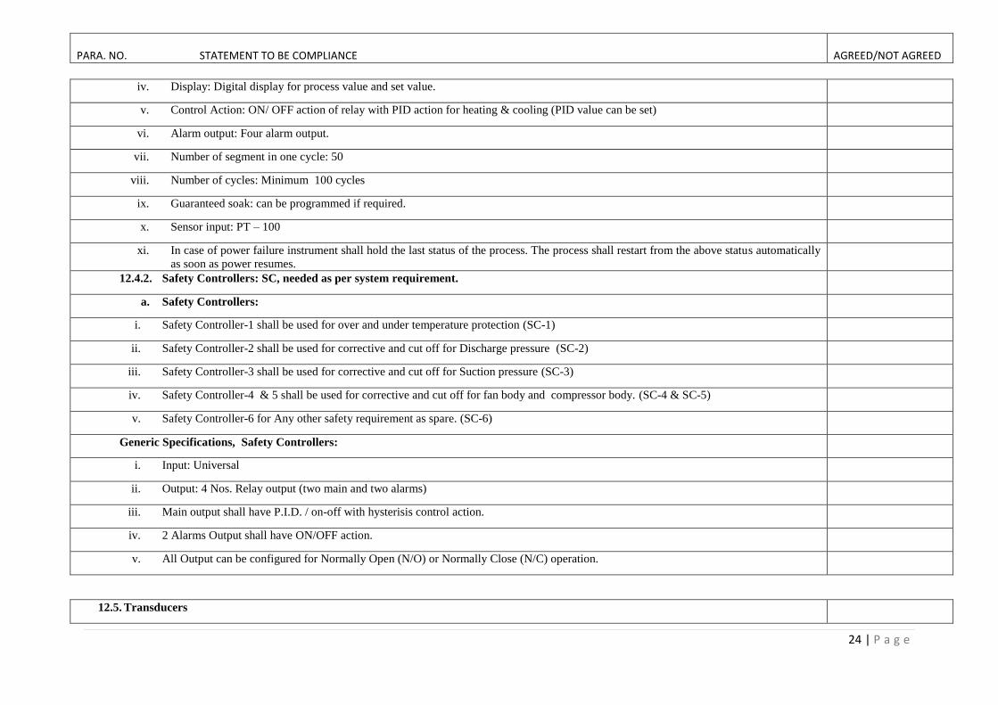
iv. Display: Digital display for process value and set value.
v. Control Action: ON/ OFF action of relay with PID action for heating & cooling (PID value can be set)
vi. Alarm output: Four alarm output.
vii. Number of segment in one cycle: 50
viii. Number of cycles: Minimum 100 cycles
ix. Guaranteed soak: can be programmed if required.
x. Sensor input: PT – 100
xi. In case of power failure instrument shall hold the last status of the process. The process shall restart from the above status automatically
as soon as power resumes.
12.4.2. Safety Controllers: SC, needed as per system requirement.
a. Safety Controllers:
i. Safety Controller-1 shall be used for over and under temperature protection (SC-1)
ii. Safety Controller-2 shall be used for corrective and cut off for Discharge pressure (SC-2)
iii. Safety Controller-3 shall be used for corrective and cut off for Suction pressure (SC-3)
iv. Safety Controller-4 & 5 shall be used for corrective and cut off for fan body and compressor body. (SC-4 & SC-5)
v. Safety Controller-6 for Any other safety requirement as spare. (SC-6)
Generic Specifications, Safety Controllers:
i. Input: Universal
ii. Output: 4 Nos. Relay output (two main and two alarms)
iii. Main output shall have P.I.D. / on-off with hysterisis control action.
iv. 2 Alarms Output shall have ON/OFF action.
v. All Output can be configured for Normally Open (N/O) or Normally Close (N/C) operation.
12.5. Transducers
PARA. NO. STATEMENT TO BE COMPLIANCE AGREED/NOT AGREED
25 | P a g e
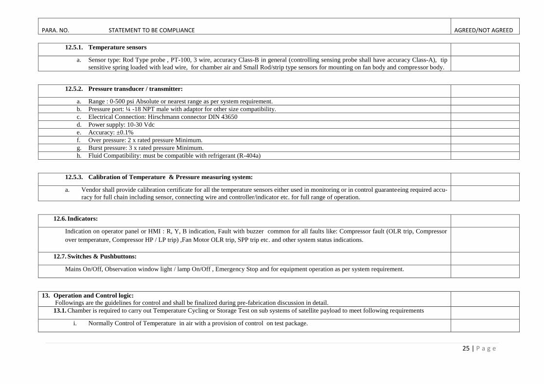
12.5.1. Temperature sensors
a. Sensor type: Rod Type probe , PT-100, 3 wire, accuracy Class-B in general (controlling sensing probe shall have accuracy Class-A), tip
sensitive spring loaded with lead wire, for chamber air and Small Rod/strip type sensors for mounting on fan body and compressor body.
12.5.2. Pressure transducer / transmitter:
a. Range : 0-500 psi Absolute or nearest range as per system requirement.
b. Pressure port: ¼ -18 NPT male with adaptor for other size compatibility.
c. Electrical Connection: Hirschmann connector DIN 43650
d. Power supply: 10-30 Vdc
e. Accuracy: ±0.1%
f. Over pressure: 2 x rated pressure Minimum.
g. Burst pressure: 3 x rated pressure Minimum.
h. Fluid Compatibility: must be compatible with refrigerant (R-404a)
12.5.3. Calibration of Temperature & Pressure measuring system:
a. Vendor shall provide calibration certificate for all the temperature sensors either used in monitoring or in control guaranteeing required accu-
racy for full chain including sensor, connecting wire and controller/indicator etc. for full range of operation.
12.6. Indicators:
Indication on operator panel or HMI : R, Y, B indication, Fault with buzzer common for all faults like: Compressor fault (OLR trip, Compressor
over temperature, Compressor HP / LP trip) ,Fan Motor OLR trip, SPP trip etc. and other system status indications.
12.7. Switches & Pushbuttons:
Mains On/Off, Observation window light / lamp On/Off , Emergency Stop and for equipment operation as per system requirement.
13. Operation and Control logic:
Followings are the guidelines for control and shall be finalized during pre-fabrication discussion in detail.
13.1. Chamber is required to carry out Temperature Cycling or Storage Test on sub systems of satellite payload to meet following requirements
i. Normally Control of Temperature in air with a provision of control on test package.

PARA. NO. STATEMENT TO BE COMPLIANCE AGREED/NOT AGREED
26 | P a g e
ii. No condensation shall occur on test package. Arrangement to be made such that condensate shall melt and flow directly to the draining
port.
iii. Cycling test shall be carrying out fully automatically, by controlling heating system, cooling System, de-humidification system and IR
lamp.
iv. Chamber shall be stopped after completion of test cycles programs.
13.2. To fulfill above requirement some of the design constraints must be understood broadly by the vendor which are explained as follows:
a. During Temperature cycling, refrigeration compressor is not required to work at higher temperature.
b. At the end of soak period at high temperature, the refrigeration system shall start.
c. Discharge pressure may increase due to working of refrigeration system at higher temperature.
d. The high pressure refrigerant shall be By-pass to Expansion Tank through By-pass solenoid vave
e. De-humidification is required while raising the temperature after completion of low temperature soak period.
f. Moreover, to ensure package temperature higher than Dew Point temperature of the air, local heating of DUT shall be carried out by IR lamps
(para 10).
g. De-humidification and lamps shall be stopped when workspace temperature is about 35°C.
h. Dehumidification is essentially required to decrease the dew point temperature of air in the workspace. 2 Nos of Dehumidifying coils are re-
quired to operate alternatively during the dehumidifying operation. Proper draining arrangement is also required to remove the condensate
from dehumidifying coil, which is not in operation and it is ensured that all condensate shall flows to draining port during dehumidification
cycle.
13.3. Above all the functions shall be carried out by four-segment control output provided in the appropriate programmer/controller.
a. Refrigeration system is getting ON at higher temperature after completion of high temperature soak period.
b. Suction pressure may be reduced during control of temperature at low set temperature, which can be compensated by switching ON bypass so-
lenoid valve from high-pressure side to ensure continuously working of the refrigeration system.
c. All types of Cooling, Heating, Dehumidification system and Local Heating Lamp shall have selectable switch, which can be set for Au-
to/Manual/ OFF. If HMI-PLC is used it can be configured on HMI screen.
d. During temperature cycling test, refrigeration system shall be off after completion of soak period of cold cycle while raising the temperature.
However, cooling system starts even at highest temperature as soon as high temperature soak period is completed and set value starts reduc-
ing.
e. In control mode at lower temperature, the main solenoid valve shall be ON/OFF. The By-pass solenoid valve-2 shall be ON as soon as suction
pressure reduces below normal working pressure.
f. Heaters ON/OFF during control at lower and higher temperature is preferred.

PARA. NO. STATEMENT TO BE COMPLIANCE AGREED/NOT AGREED
27 | P a g e
g. In spite of corrective actions specified for SC2 & SC3 cut-off, for suction and discharge pressure. If condition does not improve refrigera-
tion compressor shall be switched off.
h. Fault diagnosis for over temperature, single phasing preventer, OLR and High / Low pressure cut-off shall be indicated along with au-
dio/visual signal.
i. The Chamber shall be switched OFF if Air circulation fan is not working.
j. One set of expansion valves used shall be supplied as a spares.
Following Features applicable to: b) Hot, Cold & Humidity Chambers
14. Temperature and Humidity Requirement
14.1. Humidity Range: 40 to 95% RH in the temperature range +30ºC to +65ºC
14.2. Control Accuracy : ±3% for Humidity & ± 1 ºC for Temperature
14.3. Temperature/ RH Uniformity: Temperature uniformity ±2 & RH Uniformity ±5 %
15. Drainage arrangement in Workspace Bottom
15.1. Workspace bottom shall be joint less and proper slope shall be provided for drainage.
15.2. At the end of this slope there shall be dual level condensate draining port.
15.3. First draining port shall flush till bottom level.
a. It will remain open during temperature cyclic test and close during humidity test.
b. Arrangement shall be made in such a way that all condensate from dehumidifying coil shall directly flow to this port.
15.4. Second draining port shall have minimum 20mm height.
a. It shall remain open during humidity test and shall remain close during temperature cyclic test.
b. Water level shall be maintained to the height of the second drain port and shall also help in generating humidity by evaporation of the same
and all condensate from this port shall directly return to water level tank of the steam generator.
c. Both drain port shall have water locking arrangement to avoid infiltration of outside air with individual plugs to close during the test.
d. This bottom shall be separated by perforated sheet from work space.
16. Humidity System:
PARA. NO. STATEMENT TO BE COMPLIANCE AGREED/NOT AGREED
28 | P a g e
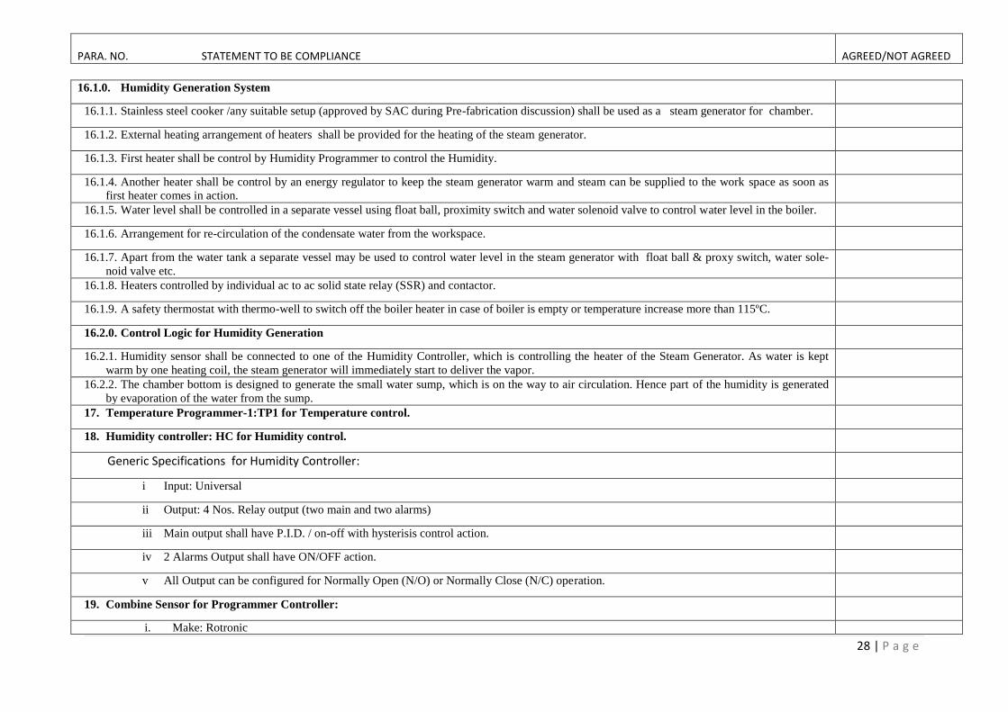
16.1.0. Humidity Generation System
16.1.1. Stainless steel cooker /any suitable setup (approved by SAC during Pre-fabrication discussion) shall be used as a steam generator for chamber.
16.1.2. External heating arrangement of heaters shall be provided for the heating of the steam generator.
16.1.3. First heater shall be control by Humidity Programmer to control the Humidity.
16.1.4. Another heater shall be control by an energy regulator to keep the steam generator warm and steam can be supplied to the work space as soon as
first heater comes in action.
16.1.5. Water level shall be controlled in a separate vessel using float ball, proximity switch and water solenoid valve to control water level in the boiler.
16.1.6. Arrangement for re-circulation of the condensate water from the workspace.
16.1.7. Apart from the water tank a separate vessel may be used to control water level in the steam generator with float ball & proxy switch, water sole-
noid valve etc.
16.1.8. Heaters controlled by individual ac to ac solid state relay (SSR) and contactor.
16.1.9. A safety thermostat with thermo-well to switch off the boiler heater in case of boiler is empty or temperature increase more than 115ºC.
16.2.0. Control Logic for Humidity Generation
16.2.1. Humidity sensor shall be connected to one of the Humidity Controller, which is controlling the heater of the Steam Generator. As water is kept
warm by one heating coil, the steam generator will immediately start to deliver the vapor.
16.2.2. The chamber bottom is designed to generate the small water sump, which is on the way to air circulation. Hence part of the humidity is generated
by evaporation of the water from the sump.
17. Temperature Programmer-1:TP1 for Temperature control.
18. Humidity controller: HC for Humidity control.
Generic Specifications for Humidity Controller:
i Input: Universal
ii Output: 4 Nos. Relay output (two main and two alarms)
iii Main output shall have P.I.D. / on-off with hysterisis control action.
iv 2 Alarms Output shall have ON/OFF action.
v All Output can be configured for Normally Open (N/O) or Normally Close (N/C) operation.
19. Combine Sensor for Programmer Controller:
i. Make: Rotronic

PARA. NO. STATEMENT TO BE COMPLIANCE AGREED/NOT AGREED
29 | P a g e
ii. Model: XB Series iii. Temperature Range: -100°C to 200° C . iv. Humidity Range: 0 to 100 % RH v. Temperature Sensor: PT-100, 3 wire
vi. Humidity Sensor:Hygromer IN-1 vii. Output for Humidity and Temperature: 4 to 20 mA, DC
20. Inspection
20.1. Following Humidity tests will be carried out:
a. 40° C / 95 % RH for 24 hours
b. 65° C / 95 % RH for 24 hours
21. Inspection, Commissioning, Transportation & Installation:
21.1. Inspection at vendor’s works.
a. Chamber shall be inspected for dimension, component make, quality of material used etc.
b. Parameters of temperature programmer / HMI + PLC unit, secondary / safety controller, data logger shall be checked.
c. Automatic and manual operation of all systems i.e. refrigeration system, dehumidification system, local heating system shall be checked.
d. Chamber shall be tested for fasted heating and cooling rate with specific load and shall be operated at highest and/or lowest temperature for
minimum 12 hours and maximum as instructed by SAC engineer.
e. Temperature control accuracy and gradient shall be checked at five different temperature in through out the range as selected by SAC engi-
neer.
f. One temperature cyclic test shall be carried out as follows. (Refer Annexure-1)
i. Cold temperature: Extreme Low as in respective column of Item.
ii. Hot temperature: Extreme High as in respective column of Item.
iii. Heating and cooling rate: Average rate as in respective column of Item.
iv. Soak period at extreme temperature: 15min.
v. Number of cycle: 5
g. Concern engineer shall issue certificate after successful acceptance test at supplier’s works to dispatch the equipment to SAC, Ahmedabad. If
required, the chamber shall be dismantled.

PARA. NO. STATEMENT TO BE COMPLIANCE AGREED/NOT AGREED
30 | P a g e
21.2. Transportation:
a. After successful inspection at supplier’s works the chamber shall be transported to SAC, Ahmedabad(or Bopal campus, Bopal, Ahmedabad as
instructed by SAC Engineer). Supplier shall take enough care for safe transport. It shall be supplier’s responsibility for safe transportation.
SAC shall provide unloading facility in the campus.
21.3. Installation at SAC:
a. Supplier shall install the chamber within one month after our confirmation.
b. After installation supplier shall demonstrate tests specified in Inspection and commissioning at suppliers works

PARA. NO. STATEMENT TO BE COMPLIANCE AGREED/NOT AGREED
31 | P a g e
2B: Vendor Profile/Information for Chambers under Category-2
1. Filling of all details are MANDATORY.
2. The details asked in BOLD letters shall be for suppliers’ evaluation/qualifying criteria.
3. Details asked in Italic are for information only but must be submitted
Clause No. Specified Requirement Compliance
Yes/No
Remarks
(if any)
1 The company shall be minimum 5 years old
Specify the Year of establishment
2 Details of the company infrastructure
Registration: Proprietary firm /Partnership/Limited
Location/Address of factory
Area of the Establishment( factory office area and manufacturing area)
Total Manpower
Yearly turn over
Other details if any
3 Bidder must be the manufacturer/authorized dealer of the similar type of Test Chambers. The bidder must have
supplied Five completed orders of the similar test chambers (having similar technical specifications) to Govern-
ment, PSUs, Reputed R & D laboratories or Reputed Pvt. Industries in India during last three years
Enclose Major specification and number of quoted ( in this quote) chambers in last 3 years
List of client for quoted ( in this quote) climatic chambers (contact person and number) supplied and executed.
Purchase Order reference ( attach the PO copy with price part marked),
Details of quoted type ( in this quote) of chamber supplied in Government, PSUs, Reputed R & D laboratories
or Reputed Pvt. Industries in last 3 years, supplied and executed.
4 Any collaboration with other company
Details of collaboration in which ( field / category/ discipline)
5 Capacity for supply of quoted ( in this quote) Hot Cold & Humidity chamber in a year.
6 Have supplied quoted chambers in any ISRO centre? If yes furnish full detail

PARA. NO. STATEMENT TO BE COMPLIANCE AGREED/NOT AGREED
32 | P a g e
2C: Format for Submission of Quote for Chambers under Category-2
1. Quote shall be furnished in this format only
2. Filling of all details are MANDATORY and shall be provide in given format only
3 The details asked in BOLD letters are evaluation/qualifying criteria. Details asked in Italic are for information but must be submitted.
SR.
No.
Point to be quote↓ Item No.→
Hot & Cold Chambers Hot, Cold & Humidity
Chambers
5 8 9 10 11 6 7 12
1. Test Space Dimensions in mm (Width x Depth x Height)
2. Test space volume in Liters
3. Nearest standard size with in + 10% volume
4. Temperature Range Low ( °C) & High (°C)
Humidity Range (%RH) with DBT Range (Where applicable)
5. Ramp Rate ( °C/ min) Heating
6. Ramp Rate ( °C/ min) Cooling
7. Control Accuracy
8. Temperature uniformity
9. Humidity Range with Temperature (Item No. 6, 7,12)
10. Humidity Control Accuracy and Uniformity (Item No. 6, 7,12)
11. Estimated overall size(External Dimensions) of total system (W x D x H) in mm
12. Estimated power rating kW (specify 1Ph or 3Ph)
13. Control system with HMI+PLC or Profile controllers specify clearly
14. Net connectivity for system visualisation & data logging
15. Price [ for quantity up to 2 Nos] with one year standard warrantee + supply +
transportation & handling charges + installation + commissioning (Total price
include all charges ) Taxes Extra
16. Price [ for quantity 3 to 5 Nos] with one year standard warrantee + supply +
transportation & handling charges + installation + commissioning (Total price
include all charges ) Taxes Extra

33 | P a g e
Category-3: Thermal Shock Chambers
PARA. NO. STATEMENT TO BE COMPLIANCE AGREE/NOT AGREE
3A: Technical Specifications
1. Basic requirement:
The Thermal shock Chambers are required for screening of electronic components and process qualification related testing of various
manufactured/processed components/samples. These tests are carried out as per latest version standards MIL-STD-202, MIL-STD-883, IEC-68 or
as per user’s requirements.
1.1: Basic Technical Requirement
1.2. Operation Requirement:
a) Internal dimensions of hot and cold zone shall have optimized dimensions to accommodate moving basket and proper arrangement of air
circulation.
b) Heating Rate in hot zone test space: 3 °C/minute (ambient to 200 ºC)
c) Cooling Rate in cold zone test space :
i ≥ 2.0 °C/minute (ambient to -70 ºC)
ii ≥ 1.5 °C/minute (ambient to -80 ºC)
Item
No.
Test Space in
Moving Basket
(W x D x H) mm
Test Space
Volume
(Litres)
Extreme temp limit in
Hot /Cold Zone (°C)*
Cooling & Heating Rate of
Each Zone (°C/minute)
Test Heat Load
Control
Accuracy (°C)
Temp
Gradient (°C) Qty.
Static
Active
Hot Cold Heating Cooling
Steel (kg) Watt -70 °C -80°C
A B C D E F G H I J K L
13 400 x 400 x 450 72 200 -80 3 2 1.5 5 NA ±1 ±3 2 No.
14 300 x 300 x 300 27 200 -80 3 2 1.5 5 NA ±1 ±3 1 No.
*Refer para 1.2 for operation requirement
ANNEXURE-3: SPECIFICATIONS CUM COMPLIANCE STATEMENT OF CLIMATIC CHAMBERS UNDER CATEGORY-3

PARA. NO. STATEMENT TO BE COMPLIANCE AGREE/NOT AGREE
34 | P a g e
d) Hot Zone test operating temperature: + 50 ºC to + 185 ºC
e) Cold Zone test operating temperature: - 70 ºC to 0 ºC
f) Recovery Time: Recovery time shall be less than 5 minutes for operating temperature range -65 ºC to 150 ºC
g) Pre-cool/offset lowest limit: - 80 ºC (Refer Column-E)
h) Pre-heat/offset highest limit: 200 ºC (Refer Column-D)
2. Structure and Construction: Thermal shock chamber
2.1. The construction shall be vertical type in which Hot zone shall be above Cold zone. The chamber shall rest on the structure.
2.2. The Structural lay out of chambers shall be as per attached drawings in Appendix-2.
2.3. Refrigeration System shall be accommodated in bottom/rear portion of the Cold zone. Rear portion of the Hot zone shall be used for Electrical
and Operator panel. The exact locations of these panels shall be finalized during pre-fabrication discussion.
2.4. Inner workspace shall be made from 20 gauge, SS 304 sheet.
2.5. Outer workspace shall be made from SS 304 sheet. However, outer bottom of the Cold zone shall be made from 20 gauge, SS 304 sheet.
2.6. Inner skeleton of the chamber shall be made from heavy gauge SS304 structural member.
2.7. Insulation: High density (min 13 )white fiber glass wool sheets/mattress shall be used for thermal insulation.
2.8. Insulating / Bakelite sheet shall be used at joining point of inner and outer wall of chamber.
2.9. Chamber side wall must be thicker than 100 mm and wall between two zone must be thicker than 200mm.
2.10. External dimensions of each chamber shall be optimized with actual test space. Chambers shall be made in such a way that these may transport
through door having 204 cm Height and 165 cm width.
2.11. Outer body of the chamber shall have powder coating / buff finish. Color shade shall be intimated at the time of pre-fabrication discussion.
2.12. Minimum four lockable heavy duty non-metallic castor wheels of sufficient weight carrying capacity shall be provided. If required quantity of
caster wheels shall be increased up to six.
2.13. The total system shall have proper ventilation, adequate spacing between components for maintenance aspect and low noise level < 70db.
3. Doors
3.1. Both the zone shall have individual insulated doors.
3.2. Door should have the same thickness as of chamber side wall.
3.3. Observation Window: Hot zone door shall have multilayer Observation window with illumination at appropriate location. Size of the window
shall be decided at the time of pre-fabrication discussion.
3.4. Two silicone/other suitable rubber gaskets with sufficient temperature bearing capacity as per temperature of the system shall be provided on
each door.
3.5. Cold zone shall be closed with one additional removable sheet to avoid condensation. RTV shall be applied on matting surface of the sheet.
3.6. Handel on right side with Positive locking arrangement (preferably with two clamps) and Heavy duty hinges on left side of both the doors. .
3.7. All hardware shall be made from either SS or brass/bronze with hard chrome plating.
3.8. Door limit switch to be provided for hot zone and arrangement to be made in such a way that if hot zone is locked cold zone door cannot be
open.
3.9. It is required to be interlock in control logic such that if door is open all systems of should be turned off.

PARA. NO. STATEMENT TO BE COMPLIANCE AGREE/NOT AGREE
35 | P a g e
3.10. Anti-sagging arrangement for door shall be provided, particularly in close condition.
4. Drain Port:
4.1. Drain port shall be provided in the bottom of the cold zone and proper slop of ~3° to prevent accumulation of water.
4.2. Location of the port shall be nearer to the evaporating coil.
4.3. Outlet of the drain shall be connected to rear end with proper provision for air locking.
5. Fan Motors and Air Circulation
5.1. Fan motor must be 3 phase induction motor with single joint less long shaft made of S.S. properly balanced to avoid any noise and vibration
during operation both the zones.
5.2. SS Axial fan shall be used. Only S.S. Nut / bolt must be used to mount fan on motor shaft.
5.3. Fans shall have enough capacity to maintain specified gradient in the work space.
6. Basket
6.1. Basket shall be fabricated from SS sheet. It shall have clear space as per system requirement and shall have low thermal mass.
6.2. Upper & Lower end shall have adequate insulation thickness to take care of both zone extreme temperatures.
6.3. Upper and lower end shall have flanges with silicone rubber gasket to avoid mixing of air of both the zones.
6.4. The basket shall have two S.S. shelves for keeping Device Under Test ( 5 kg weight capacity).
6.5. Partition of Hot and Cold zones shall have precise cutout for basket movement, which shall also work as a guide for the basket.
6.6. There shall be an access port of minimum 50mm dia to draw the wire harness to take out for electrical wires for connecting the measurement
setup outside the zones and it shall have adequate provision for not exposing to the temperatures of zones during basket travel.
7. Basket transfer mechanism:
7.1. Pneumatic /motorized system shall be provided for basket transfer.
7.2. Basket transfer time shall not be more than 10 seconds with load.
7.3. In case of Pneumatic system following feature
7.3.1. It shall consist of pneumatic cylinder, pressure regulator, two way pneumatic solenoid valve, air flow regulator etc.
7.3.2. The pneumatic cylinder shall have in built magnetic proximity switches to sense the position of the basket in Hot or Cold zone.
7.3.3. Pneumatic cylinder shall be mounted on top of the chamber in such a way that it could be removed during transportation. Exact scheme shall be
decided during final engineering stage.
7.3.4. During operation piston rod should be in air and basket shall be connected through connecting rods arrangement. Proper arrangement shall be
done for smooth movement of these rods during basket transfer from hot zone to cold zone and vise a versa.
7.3.5. Pneumatic cylinder shall be capable of transferring the basket with load in specified time.
7.3.6. Air compressor :Compact sized High Speed, low noise operation, Oil free air compressor shall be provided to support the pneumatic system and
it is preferred to accommodated inside the structure.
7.4. In case of mortised system provision of VFD to motor to vary travel time which shall be programmable.

PARA. NO. STATEMENT TO BE COMPLIANCE AGREE/NOT AGREE
36 | P a g e
8. Dry Heating System
8.1. S.S. Jacketed Electrical Resistance air heater of sufficient capacity, to take care of specified heating rate with safety margin.
8.2. Heaters in star connection to equally distribute the load, controlled by individual ac to ac solid state relay (SSR), contactor, energy regulator and
over temperature controller.
9. Cooling System:
9.1. Lowest temperature in the cold zone shall be achieved by cascade refrigeration system. Semi-sealed refrigeration compressors shall be used for
High stage( R-404A) and Low stage (R-23 or R-508B/Suva-95) refrigeration systems.
9.2. General requirements refrigeration system
9.2.1. The compressor and condenser shall be air cooled only.
9.2.2. Thermostatic expansion valve must be used in high stage and low stage refrigeration system for expansion of refrigerant.
9.2.3. Small cooling fans to be provided for both refrigeration compressors for cooling of compressor.
9.2.4. Sight glass to be provided for both the refrigeration system.
9.2.5. Thermostatic expansion valves, Oil separators, Dryers, bellows type vibration accumulator joints at discharge & suction, vibration isolators for
refrigeration compressors etc. shall be used in refrigeration system. Expansion tank shall be used in LSRS. System shall have Main solenoid
valve and various High and Low Pressure By-pass solenoid valves. Overall details shall be finalized during pre fabrication discussion.
9.2.6. Pressure transmitters and electronic controllers shall be used for pressure measurement and control. Technical details are given in Electrical
section.
9.2.7. Suction line shall be maintained as short as possible.
9.3. The provision for cooling below -80°C
9.3.1. The further lower cooling shall be achieved through LN2 injection in work space. Suitable arrangement for connecting LN2 dewar to be
made to provide controlled LN2 injection and it shall be configured in such a way that cooling shall be through LN2 cooled coil/direct
injection and in this configuration refrigeration system shall be off.LN2 Dewar is not in the scope of supply.
9.3.2. Cryogenic SV (¼ inch size) shall control the LN2 flow to control the temperature.
9.3.3. All control logic explained for cascade cooling shall be applicable to LN2 mode operation also.
10. Defrosting System
10.1. Cold zone shall have defrosting heaters of approximately of 1 Kw capacities. These electrical resistance heaters shall be controlled by SSR which
get ON by lower zone temperature controller.
11. Operator & Electrical Panel with data logging
11.1. Electrical panel
PARA. NO. STATEMENT TO BE COMPLIANCE AGREE/NOT AGREE
37 | P a g e
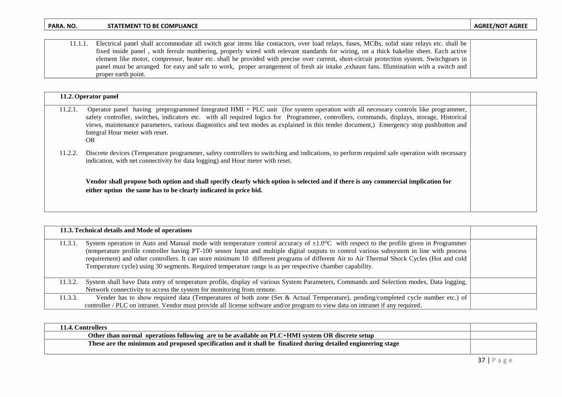
11.1.1. Electrical panel shall accommodate all switch gear items like contactors, over load relays, fuses, MCBs, solid state relays etc. shall be
fixed inside panel , with ferrule numbering, properly wired with relevant standards for wiring, on a thick bakelite sheet. Each active
element like motor, compressor, heater etc. shall be provided with precise over current, short-circuit protection system. Switchgears in
panel must be arranged for easy and safe to work, proper arrangement of fresh air intake ,exhaust fans. Illumination with a switch and
proper earth point.
11.2. Operator panel
11.2.1. Operator panel having preprogrammed Integrated HMI + PLC unit (for system operation with all necessary controls like programmer,
safety controller, switches, indicators etc. with all required logics for Programmer, controllers, commands, displays, storage, Historical
views, maintenance parameters, various diagnostics and test modes as explained in this tender document,) Emergency stop pushbutton and
Integral Hour meter with reset.
OR
11.2.2. Discrete devices (Temperature programmer, safety controllers to switching and indications, to perform required safe operation with necessary
indication, with net connectivity for data logging) and Hour meter with reset.
Vendor shall propose both option and shall specify clearly which option is selected and if there is any commercial implication for
either option the same has to be clearly indicated in price bid.
11.3. Technical details and Mode of operations
11.3.1. System operation in Auto and Manual mode with temperature control accuracy of ±1.0°C with respect to the profile given in Programmer
(temperature profile controller having PT-100 sensor Input and multiple digital outputs to control various subsystem in line with process
requirement) and other controllers. It can store minimum 10 different programs of different Air to Air Thermal Shock Cycles (Hot and cold
Temperature cycle) using 30 segments. Required temperature range is as per respective chamber capability.
11.3.2. System shall have Data entry of temperature profile, display of various System Parameters, Commands and Selection modes, Data logging,
Network connectivity to access the system for monitoring from remote.
11.3.3. Vender has to show required data (Temperatures of both zone (Set & Actual Temperature), pending/completed cycle number etc.) of
controller / PLC on intranet. Vendor must provide all license software and/or program to view data on intranet if any required.
11.4. Controllers
Other than normal operations following are to be available on PLC+HMI system OR discrete setup
These are the minimum and proposed specification and it shall be finalized during detailed engineering stage

PARA. NO. STATEMENT TO BE COMPLIANCE AGREE/NOT AGREE
38 | P a g e
11.4.1. Temperature Programmer-1:TP1 for Temperature control
i. Temperature Range: as per system requirement
ii. Resolution : 0.1° C
iii. Control accuracy : Better than +/- 1.0° C
iv. Display: Digital display for process value and set value.
v. Control Action: ON/ OFF action of relay with PID action for heating & cooling (PID value can be set)
vi. Alarm output: Four alarm output.
vii. Number of segment in one cycle: 10
viii. Number of cycles: Minimum 1000 cycles
ix. Guaranteed soak: can be programmed if required.
x. Sensor input: PT – 100
xi. In case of power failure instrument shall hold the last status of the process. The process shall restart from the above status automatically as
soon as power resumes.
11.4.2. Temperature controller TC : Hot Controller SC-1 and Cold Controller SC-2 for control of Hot zone and Cold zone as per system
requirement with following generic specification
a. Input: Universal/PT 100
b. Output: 4 Nos. Relay output (two main and two alarms)
c. Main output shall have P.I.D. / on-off with hysteresis control action.
d. 2 Alarms Output shall have ON/OFF action.
e. All Output can be configured for Normally Open (N/O) or Normally Close (N/C) operation.
11.4.3. Safety Controllers: SC, needed as per system requirement
a. Safety Controllers:
i. Safety Controller-1 for over temperature protection. SC-1
ii. Safety Controller-2 for under temperature protection. SC-2
iii. Safety Controller-3 for corrective and cut off for Discharge pressure(HS). SC-3
iv. Safety Controller-4 for corrective and cut off for Suction pressure(HS). SC-4
v. Safety Controller-5 for corrective and cut off for Discharge pressure(LS). SC-5
vi. Safety Controller-6 for corrective and cut off for Suction pressure(LS). SC-6
vii. Safety Controller-7 for over and under temperature of cascade condenser/coil. SC-7
viii. Safety Controller-8 & 9 for corrective and cut off for fan body (hot and cold zone). SC-8 & SC-9
ix. Safety Controller-10 for Any other safety requirement as spare. SC-10
a. Major generic specification same as for Temperature controller TC
11.5. Transducers
11.5.1. Temperature sensors
a. Sensor type: Rod Type probe , PT-100,3 wire, accuracy Class-B in general (controlling sensing probe shall have accuracy Class-A) , tip

PARA. NO. STATEMENT TO BE COMPLIANCE AGREE/NOT AGREE
39 | P a g e
sensitive spring loaded with lead wire, for chamber air and Small Rod/strip type sensors for mounting on fan body.
11.5.2. Pressure transducer / transmitter:
a. Range : 0-500 psi Absolute or nearest range as per system requirement.
b. Pressure port: ¼ -18 NPT male with adaptor for other size compatibility.
c. Electrical Connection: Hirschmann connector DIN 43650
d. Power supply: 10-30 Vdc
e. Accuracy: ±0.1%
f. Over pressure: 2 x rated pressure Minimum
g. Burst pressure: 3 x rated pressure Minimum.
h. Fluid Compatibility: must be compatible with refrigerant (R-404a &R23)
11.5.3. Calibration of Temperature & Pressure measuring system:
a. Vendor shall provide calibration certificate for all the temperature sensors either used in monitoring or in control guaranteeing required
accuracy for full chain including sensor, connecting wire and controller/indicator etc. for full range of operation.
11.6. Indicators:
Indication on operator panel or HMI : R, Y, B indication, Fault with buzzer common for all faults like: Compressor fault (OLR trip, Compressor
over temperature, Compressor HP / LP trip) ,Fan Motor OLR trip, SPP trip etc. and other system status indications.
11.7. Switches & Pushbuttons:
Mains On/Off, Observation window light / lamp On/Off , Emergency Stop and for equipment operation as per system requirement..
11.7.1. Alarm with message and buzzer following minimum events.:
a. During transfer of basket (missing of the basket)
b. Low Pneumatic pressure
c. SPP (Single phase preventer Relay / Unit)
d. Over temperature in Hot zone
e. HS compressor motor temperature high
f. LS Compressor motor temperature high
g. HS suction pressure low
h. HS discharge pressure high
i. LS suction pressure low
j. LS discharge pressure high
k. Hot zone air circulating fan not working
l. Cold zone air circulating fan not working

PARA. NO. STATEMENT TO BE COMPLIANCE AGREE/NOT AGREE
40 | P a g e
12. Over all Control logic:
12.1. Followings are the guidelines for control and shall be finalized during pre fabrication discussion in detail.
i. Loading of the test item shall be possible from Hot zone only.
ii. After completion of the test, in case of power failure or if de-frosting is selected in between the test, basket shall be transferred to Hot zone.
iii. In case of power failure or restarting the test after de-frosting, the test shall be restarted from the last cycle completed.
iv. The basket position shall be detected by the magnetic proximity switch provided in the pneumatic cylinder.
v. Both the zone shall maintain test temperature when basket is there in the respective zone by programmer.
vi. The other zone’s temperature shall be controlled by respective temperature controller (SC-1 / SC-2)
vii. Elevated temperature shall be maintained when basket is not in the zone. It shall be maintained by respective additional controller. This is
required to decrease the temperature recovery period after transfer of the basket.
viii. A selector switch shall be provided for TEST mode or DE- FROSTING mode operation.(For manual defrosting)
ix. A selector switch shall be provided for AUTOMATIC or MANUAL mode, Up and Down operation of the basket.
12.2. Starting logic
a. A pressure switch is provided for pneumatic system.
b. A single phase preventer (SPP) is provided for incoming phase.
c. One auxiliary contact of the programmer is used, which shall remain ON during testing. It shall be programmed in such a way that it shall be
OFF at the end of the test to switch off the main contactor to switch off the chamber.
d. Mains contactor shall be ON when all above three conditions are OK with mains switch is ON.
e. Programmer shall control the temperature of the respective zone, where basket shall remain present. It shall be possible by changing the sensor
input automatically with respect to basket position.
12.3. Control logic of the programmer (Main) and controllers SC-1( Hot) & SC-2 (Cold)
a. Hot zone shall be controlled by the programmer when basket is in Hot zone.
b. Whereas the Hot zone shall be controlled by the Controller SC-1 when basket is not in the Hot zone.
c. Alarm contact of the controller SC-1 is used as an Over temperature protection of the Hot zone as explained in the respective pare.
d. Similarly, Cold zone shall be controlled by the programmer when basket is in Cold zone.
e. Whereas the Cold zone shall be controlled by the controller SC-2 when basket is not in the Cold zone.
f. One Alarm contact of the controller SC-2 is used as a set temperature to control + 40 ºC in defrosting mode.
g. Temperature sensors of Hot zone and Cold zone are connected to the programmer as required depending upon the basket position.
h. Additional sensors for the controllers SC-1 & SC-2 are fixed in the respective zones.
i. The programmer shall have two main outputs, one for cooling and another for heating.
j. The programmer shall have four auxiliary programmable event outputs, which are used for following purpose:
i. To control pneumatic solenoid valve to change the basket position.
ii. To give signal to external counter at the end of cycle.
iii. To switch-off control Main contactor at the end of required number of cycles.
k. There shall be temperature sensors on cascade condenser which shall used to monitor the temperature and shall switch-off respective
compressor in case of temperatures reach above the set value.

PARA. NO. STATEMENT TO BE COMPLIANCE AGREE/NOT AGREE
41 | P a g e
12.4. Control logic for pneumatic system
a. 2 x 3 port single coil (230 volt/ac) type pneumatic solenoid valve shall be used.
b. An auxiliary contact shall be programmed to energize the pneumatic solenoid when basket is supposed to be in Cold zone.
c. It shall be configured in such a way that when coil is energized, the basket shall be pushed to Cold zone and when coil in off condition, the
basket shall be pushed to Hot zone.
d. The pneumatic cylinder shall have fast response magnetic proximity switches on both the end to indicate the basket position.
e. Vendor has to provide two such proximity switch as a spare.
f. Either shaft sealing of the pneumatic cylinder shall be capable of withstanding high shaft temperature or arrangement shall be made to avoid
such situation. Vendor shall adopt standard sealing systems used for such system with proven design and heritage.
12.5. Control logic for refrigeration system
12.5.1. High stage refrigeration system (HSRS)
a. HS refrigeration compressor shall start after preset time delay (TM-1) if:
Chamber fan is on.
Condenser fan is on.
Abnormal suction pressure is within limit.
Compressor motor winding temperature is within limit.
OLR cum SPP is normal.
b. HS_LP_SV shall be ON during the time delay for equalization of the pressure.
c. HS_LP_SV shall be ON in case if suction pressure is reduced below normal suction pressure level. It is to avoid tripping of the HS compressor
d. The HS compressor shall be OFF in case if suction pressure is reducing below abnormal level.
e. HSRS shall cool down the cascade condenser to approx. - 25 ºC, which shall be sensed by a controller (SC-7).
12.5.2. Low stage refrigeration system (LSRS)
a. LS refrigeration compressor shall start after Time delay (TM-2) if:
Cascade temperature is achieved.
Abnormal suction and discharge pressure is within limit.
Compressor motor winding temperature is within limit.
OLR cum SPP is normal.
b. LS_LP_SV shall be ON during the time delay for equalization of the pressure.
c. LS_LP_SV shall be ON in case if suction pressure is reduced below normal suction pressure level. It is to avoid tripping of the LS compressor.
d. LS_HP_SV shall be ON in case if discharge pressure is increasing above normal discharge pressure level. It is also to avoid tripping of the LS
compressor
e. MSV shall be controlled by:
Cooling output of the programmer, when basket is in the Cold zone.

PARA. NO. STATEMENT TO BE COMPLIANCE AGREE/NOT AGREE
42 | P a g e
Cooling output of the controller (SC-2), when basket is not in the Cold zone. SC-2 is set at lower than test temperature so that recovery of
the temperature shall be faster after transfer of the basket from hot zone to cold zone.
f. The LS compressor shall be OFF in case if suction pressure is reducing below or discharge pressure is increasing above abnormal level.
12.5.3. Control logic for heating system (Hot zone)
a. Required capacities of the heaters shall be equally distributed in three phases and connected in star connection.
b. The heaters shall be energized by ac to ac type solid state relay (SSR) and protected by the suitable MCB.
c. Star connection of the heaters is generated through a contactor, which is continuously remains ON through alarm contact of the controller SC-1.
In case of over temperature in the Hot zone, SC-1 shall trip the contactor.
12.5.4. Control logic for defrosting system
a. Selectors switch to be provided for TEST MODE/DEFROSTING MODE.
b. Defrosting operation shall start by selecting the mode.
c. It shall switch off the refrigeration system and basket shall be transferred to hot zone, but air circulation fans remains ON.
d. Heaters in the Cold zones are energize through contactor and protected through MCB. Alarm-1 contact of the controller SC-2 will operate this
contactor to control cold zone temperature appx. at +40ºC.
e. Operator shall turn the selector switch to TEST MODE and remaining test shall restart. Chamber program must start from where it was stopped.
12.5.5. Control logic for Pressure measurement & protection
Pressure measurement & cutoff control shall be carried out using pressure transmitters interfaced controllers shall execute the control action as per system
requirement.
a. HS discharge pressure (P-1)
Shall switch off the HSRS, if pressure is increasing above abnormal level
b. HS suction pressure (P-2)
Shall switch on the HS_LP_SV, if pressure is decreasing below normal level
Shall switch off the HSRS, if pressure is decreasing below abnormal level
c. LS discharge pressure (P-3)
Shall switch on the LS_HP_SV, if pressure is increasing above normal level
Shall switch off the LSRS, if pressure is increasing above abnormal level
d. LS suction pressure (P-4)
Shall switch on the LS_LP_SV, if pressure is decreasing below normal level
Shall switch off the LSRS, if pressure is decreasing below abnormal level
13. Inspection, Commissioning, Transportation And Installation:
13.1. Inspection and commissioning at suppliers works:
a. The chamber shall be inspected for dimension, make and quality of materials used etc.

PARA. NO. STATEMENT TO BE COMPLIANCE AGREE/NOT AGREE
43 | P a g e
Parameters of programmer and controllers and other logics shall be checked.
Specified cooling rate and heating rate of the Cold zone and Hot zone with basket and specified heat load shall be checked.
b. Thermal Shock test shall be carried out as follows:
Hot zone temperature: 150° C with offset/pre-heat temperature 165 °C
Cold zone temperature: -65° C with offset/pre-cool temperature -75 °C
Soak period at extreme temperature: 15 min with guaranteed soak
No. of test Cycles: 15
Working of various pressure transmitter with controllers shall be observed.
Temperature control accuracy and uniformity shall be checked at 60°C, 80°C,100°C,150°C & 180 °C in Hot zone and at -40°C, -55°C , -70°C
in Cold zone.
c. Concern engineer shall issue certificate after successful completion of acceptance test at supplier’s works to dispatch the equipment to SAC,
Ahmedabad. If required, the chamber shall be dismantled by the vendor and packed properly before transportation.
13.2. Transportation:
After successful inspection at supplier’s works the chamber shall be transported to SAC, Ahmedabad. Supplier shall take enough care for safe
transport. It shall be supplier’s responsibility for safe transportation to SAC, Ahmedabad. SAC shall provide unloading facility in the campus.
13.3. Installation at SAC:
Supplier shall install the chamber within one month after our confirmation.
After installation supplier shall demonstrate tests specified in Inspection and commissioning at suppliers works

PARA. NO. STATEMENT TO BE COMPLIANCE AGREE/NOT AGREE
44 | P a g e
3B: Vendor Profile/Information for Thermal Shock Chambers under Category-3
1. Filling of all details are MANDATORY.
2. The details asked in BOLD letters shall be for suppliers’ evaluation/qualifying criteria.
3. Details asked in Italic are for information only but must be submitted
Clause No. Specified Requirement Compliance
Yes/No
Remarks
(if any)
1 The company shall be minimum 5 years old
Specify the Year of establishment
2 Details of the company infrastructure
Registration: Proprietary firm /Partnership/Limited
Location/Address of factory
Area of the Establishment( factory office area and manufacturing area)
Total Manpower
Yearly turn over
Other infrastructure details of the company
3 Bidder must be the manufacturer/authorized dealer of the similar type of Test Chambers. The bidder must have
supplied Three completed orders of the similar test chambers (having similar technical specifications) to Government,
PUC, Reputed R & D laboratories or Reputed Pvt. Industries in India during last three years
Enclose Major specification and number of quoted ( in this quote) chambers in last 3 years
List of client for quoted ( in this quote) climatic chambers (contact person and number) supplied and executed.
Purchase Order reference ( attach the PO copy with price part marked)
Details of quoted type ( in this quote) of chamber supplied in Government, PUC, Reputed R & D laboratories or
Reputed Pvt. Industries in last 3 years, supplied and executed.
4 Any collaboration with other company
Details of collaboration in which ( field / category/ discipline)
5 Capacity for supply of quoted ( in this quote) Thermal Shock chamber in a year.
6 Have supplied quoted chambers in any ISRO centre? If yes furnish full detail

PARA. NO. STATEMENT TO BE COMPLIANCE AGREE/NOT AGREE
45 | P a g e
3C: Format of Quotation for Thermal Shock Chambers under Category-3
1. Quote shall be furnished in this format only.
2. Filling of all details are MANDATORY and shall be provide in given format only.
3 The details asked in BOLD letters are evaluation/qualifying criteria. Details asked in Italic are for information but must be submitted.
Sr No.
Points to be Quote↓ Item No → 13 14
1. Test Space Dimensions (work space in moving trolley) in mm (Width x Depth x Height)
2. Test space volume in Liters
3. Nearest standard size with in + 10% volume
4. Temperature Range of Hot Zone & Cold Zone ( °C)
5. Average Ramp Rate (Ambient to Extreme High) of Hot Zone ( °C/ min)
6. Average Ramp Rate (Ambient to Extreme Low) of Cold Zone ( °C/ min)
7. Control Accuracy of each Zone
8. Temperature uniformity of Each Zone
9. Estimated overall size (External Dimensions) of total system (W x D x H) in mm
10. Estimated power rating kW (specify 1Ph or 3Ph)
11. Control system with HMI+PLC or Profile controllers specify clearly
12. Net connectivity for system visualization & data logging
13. Price [ for quantity up to 2 Nos] with one year standard warrantee + supply + transportation & handling
charges + installation + commissioning (Total price include all charges ) Taxes Extra
14. Price [ for quantity 3 to 5 Nos] with one year standard warrantee + supply + transportation & handling
charges + installation + commissioning (Total price include all charges ) Taxes Extra

46 | P a g e
Category-4: Hot chambers/Ovens
PARA NO. STATEMENT TO BE COMPLIANCE
AGREE/NOT AGREE
4A: Basic Technical Specifications
1. Basic requirement:
In a single unit, one or more than one independent Hot Workspace/s to carry out various hot storage/operational tests at different temperatures
simultaneously/Independently. The temperature in each workspace may be same or different.
1.1: Technical Requirement
2. Structure and Construction:
2.1. Over all construction of chamber shall be bench type.
Item
No.
Test Work Space
(W x D x H) mm
Volume
(Litres)
Operating Temp Range
at Ambient
Average Transition Rate
from Ambient (°C/minute)
Test Heat Load Control
Accuracy (°C)
Temp
Gradient (°C) Qty.
Static
Passive
High (°C) Low (°C) Heating Cooling Steel (kg) Watt
A B C D E F G H I J K L
15 800 x 500 x 500 (each) (2 workspace in 1 unit)
200 350 Amb+20 7 NA 5 NA ±1 ±3 1 No.
16 300 x 300 x 300 27 350 Amb+20 7 NA 5 NA ±1 ±3 1 No.
17 800 x 500 x 500 (each) (2 workspace in 1 unit)
200 200 Amb+10 5 NA 5 NA ±1 ±2 1 No.
18 1000 x 1000 x 500 500 200 Amb+10 5 NA 5 NA ±1 ±2 2 No.
19 400 x 500 x 500 (each) (4 workspace in 1 unit)
100 150 Amb+10 5 NA 5 NA ±1 ±2 1 No.
ANNEXURE-4: SPECIFICATIONS CUM COMPLIANCE STATEMENT OF CLIMATIC CHAMBERS UNDER CATEGORY-4

PARA NO. STATEMENT TO BE COMPLIANCE AGREE/NOT AGREE
47 | P a g e
2.2. The Structural lay out of chambers shall be as per attached drawings in Appendix-2
2.3. Chamber bench shall be constructed in such a way that workspace bottom of lower zone (applicable for Item No 17 & 19) shall be at minimum
300mm from the floor level. It must be covered with S.S. detachable panel/cover.
2.4. In case of multi-work space chambers, each chamber can be detached and it shall have all its heaters, controllers, fans, electrical hardware to have
independent chamber module and shall have minimum 50mm detachable stand.
2.5. The chamber shall have double wall type construction with minimum 50 mm insulation thickness with optimum density of Glass wool /Fiber
Glass/Mineral wool / Ceramic fiber to take care of heat loss from the workspace and avoid hot spots on exterior wall.
2.6. Chamber Material : Inner and outer wall shall be made out of bright polished / buffed S.S. 304, 20 gauge sheet. Locking handles, hinges etc. can be
MS/Brass with hard chrome plating.
2.7. Inner skeleton of the chamber shall be made from appropriate structural member.
2.8. M.S. section shall be used for support frame work and bench structure.
2.9. Support frame and bench must be painted either powder coating or epoxy paint and it must not be visible..
2.10. Caster Wheels: Four lockable non-metallic heavy duty castor wheels of sufficient weight carrying capacity shall be mounted for easy movement of
the chamber on floor. One set of heavy duty caster wheels shall provided as spares.
3. Doors: doors with door limit switch:
3.1. Each zone should have individual doors with door limit switch.
3.2. Door should have made using same material and thickness as of chamber, with limit switch.
3.3. Handle on right side with Positive locking arrangement (preferably with two clamps) and Heavy duty hinges on left side of the door.
3.4. Double layer silicon (up to 200°C range of chamber) or asbestos /cellulose type (above 200°C chamber ) gasket shall be provided for proper sealing
of the door with chamber.
3.5. Multilayer Observation window with illumination shall be provided in door. Size of the window shall be decided at the time of pre fabrication
discussion.
3.6. Anti-sagging arrangement for door shall be provided, particularly in close condition.
4. S.S. shelves:
4.1. Two S.S. shelves for keeping Device Under Test ( 5 kg weight capacity), which can be adjusted throughout the height, made from S.S. net such that
it must not restrict air flow of the chamber.
5. Port Holes:
5.1. One port hole with plug shall be provided. Size and location of port hole shall be finalized at the time of prefabrication discussion.
6. Fan Motors and Air Circulation:
6.1. Fan motor must be three phase/single phase induction motor with joint less long shaft made of S.S. properly balanced to avoid any noise and
vibration during operation.
6.2. SS Axial fan shall be used. Only S.S. Nut / bolt must be used to mount fan on motor shaft.
6.3. Sufficient air circulation shall be provided to achieve specified temperature gradient.
6.4. Separate fan motors for individual zone must be used. Fan motor shall be mounted on the rear side of the chamber above the center line.

PARA NO. STATEMENT TO BE COMPLIANCE AGREE/NOT AGREE
48 | P a g e
6.5. About 20mm gap shall be provided between chamber wall and front mounting flange of the motor.
6.6. Air shall be sucked by the fan from the workspace, flown down to bottom and entering to workspace for uniform distribution.
6.7. There shall be provision for intake of the fresh air and to exhaust hot air with hand shut-off valve or similar type arrangement.
6.8. A small heat swing fan on the motor shaft shall be provided in this gap to remove heat from the shaft and to protect the front bearing of the motor.
6.9. Chambers below 200 °C shall be capable for continuous operation up to 2000 hours.
6.10. Maintainability: Partition for air circulation shall be designed in such a way that fan & heaters shall have accessibility from maintenance point of
view.
7. Dry Heating System:
7.1. S.S. Jacketed Electrical Resistance air heater / Mineral insulated metal sheathed heating elements of sufficient capacity, to take care of specified
heating rate with safety margin.
7.2. Heaters in star connection to equally distribute the load, controlled by individual ac to ac solid state relay (SSR), contactor, energy regulator and
over temperature controller.
8. Operator & Electrical Panel with data logging (For each work space):
8.1. Electrical panel:
8.1.1. Electrical panel shall accommodate all switch gear items like contactors, over load relays, fuses, MCBs, solid state relays etc. shall be fixed inside
panel, with ferrule numbering, properly wired with relevant standards for wiring, on a thick bakelite sheet. Each active element like motor, heater
etc. shall be provided with precise over current, short-circuit protection and proper earth point.
8.1.2. Discrete devices (Temperature programmer, safety controllers to switching and indications, to perform required safe operation with necessary
indication, with net connectivity for data logging) and Hour meter with reset.
8.2. Technical details and Mode of operations:
8.2.1. System operation in Auto and Manual mode with temperature control accuracy of ±1.0°C with respect to the profile given in Programmer
(temperature profile controller having PT-100 sensor input. Data logging, Network connectivity to access the system for monitoring from remote.
8.3. Controllers:
8.3.1. Temperature Programmer-1:TP1 for Workspace Temperature control :
i. Temperature Range: as per system requirement
ii. Resolution : 0.1° C or 1 ° C
iii. Control accuracy : Better than +/- 1.0° C
iv. Display: Digital display for process value and set value.
v. Control Action: ON/ OFF action of relay with PID action for Ramp up & Ramp dn (PID value can be set)
vi. Alarm output: Four alarm output.
vii. Number of segment in one cycle: Minimum 20 segments
viii. Number of cycles: Minimum 10 cycles
ix. Guaranteed soak: can be programmed if required.
x. Sensor input: PT – 100

PARA NO. STATEMENT TO BE COMPLIANCE AGREE/NOT AGREE
49 | P a g e
xi. In case of power failure instrument shall hold the last status of the process. The process shall restart from the above status automatically as
soon as power resumes.
8.3.2. Safety Controllers: Three Safety Controllers (SC) are needed as per system requirement:
a. Safety Controllers:
i. Safety Controller-1 shall be used for over temperature protection.
ii. Safety Controller-2 shall be used for fan body over temperature protection.
iii. Safety Controller-3 for Any other safety requirement as spare.
Generic Specifications for Safety Controllers:
i. Input: Universal
ii. Output: 4 Nos. Relay output (two main and two alarms)
iii. Main output shall have P.I.D. / on-off with hysterisis control action.
iv. 2 Alarms Output shall have ON/OFF action.
v. All Output can be configured for Normally Open (N/O) or Normally Close (N/C) operation.
8.4. Transducers
8.4.1. Temperature sensors
a. Rod Type probe PT-100, 3 wire, accuracy Class-B in general (controlling sensing probe shall have accuracy Class-A), tip sensitive spring
loaded with lead wire suitable for the application temperature of respective hot range, for chamber air and Small Rod/strip type sensors for
mounting on fan body.
8.4.2. Calibration of Temperature sensor:
a. Vendor shall provide calibration certificate for all the temperature sensors either used in monitoring or in control guaranteeing required
accuracy for full chain including sensor, connecting wire and controller/indicator etc. for full range of operation.
8.5. Indicators:
R, Y, B indication, Fault with buzzer common for all faults like: over temperature, Fan Motor OLR trip, SPP trip etc. with indications.
8.6. Switches & Pushbuttons:
Mains On/Off, Observation window light / lamp On/Off and for equipment operation as per system requirement.
9. Operation and Control logic :
The chamber shall have fully automatic control for all parameters.
9.1. All zones shall have individual temperature control and shall be given individual temperature profile.
9.2. After loading the DUT (Device Under Test) in particular zone, operator shall program the temperature programmer to operate the particular zone.
9.3. Chamber fan must operate only after respective door limit switch is closed.
9.4. Zone heater’s SSR shall be controlled by Temperature Programmer with heating output of secondary / safety controller and ER (Energy Regulator) and
all required protection interlocks.

PARA NO. STATEMENT TO BE COMPLIANCE AGREE/NOT AGREE
50 | P a g e
10. Inspection, Transportation, Installation and Commissioning:
10.1. Inspection:
The chamber shall be inspected at vendor’s works.
i. Chamber shall be inspected for dimension, component make, quality of material used etc.
ii. Parameters of temperature programmer, secondary / safety controller, data logger, shall be checked.
iii. Each zone shall be tested for fastest heating rate with specific load and shall be operated at highest temperature for minimum 12 hours and
maximum as instructed by SAC engineer.
iv. Temperature control accuracy and temperature uniformity/gradient shall be checked at five different temperature in through out the range as
selected by SAC engineer as applicable for respective unit.
v. Concern engineer shall issue certificate after successful completion of acceptance test at supplier’s works to dispatch the equipment to SAC,
Ahmedabad. If required, the chamber shall be dismantled by the vendor and packed properly before transportation.
10.2. Transportation:
i. After successful inspection at supplier’s works the chamber shall be transported to SAC, Ahmedabad (or Bopal campus, Bopal, Ahmedabad as
instructed by SAC Engineer). Supplier shall take enough care for safe transport. It shall be supplier’s responsibility for safe transportation to
SAC, Ahmedabad. SAC shall provide unloading facility in the campus.
10.3. Installation at SAC:
i. Supplier shall install the chamber within one month after our confirmation.
ii. After installation supplier shall demonstrate tests specified in Inspection and commissioning at suppliers works
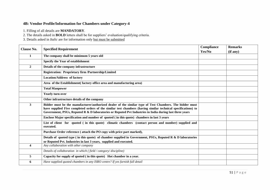
PARA NO. STATEMENT TO BE COMPLIANCE AGREE/NOT AGREE
51 | P a g e
4B: Vendor Profile/Information for Chambers under Category-4
1. Filling of all details are MANDATORY.
2. The details asked in BOLD letters shall be for suppliers’ evaluation/qualifying criteria.
3. Details asked in Italic are for information only but must be submitted
Clause No. Specified Requirement Compliance
Yes/No
Remarks
(if any)
1 The company shall be minimum 5 years old
Specify the Year of establishment
2 Details of the company infrastructure
Registration: Proprietary firm /Partnership/Limited
Location/Address of factory
Area of the Establishment( factory office area and manufacturing area)
Total Manpower
Yearly turn over
Other infrastructure details of the company
3 Bidder must be the manufacturer/authorized dealer of the similar type of Test Chambers. The bidder must
have supplied Five completed orders of the similar test chambers (having similar technical specifications) to
Government, PSUs, Reputed R & D laboratories or Reputed Pvt Industries in India during last three years
Enclose Major specification and number of quoted ( in this quote) chambers in last 3 years
List of client for quoted ( in this quote) climatic chambers (contact person and number) supplied and
executed.
Purchase Order reference ( attach the PO copy with price part marked),
Details of quoted type ( in this quote) of chamber supplied in Government, PSUs, Reputed R & D laboratories
or Reputed Pvt. Industries in last 3 years, supplied and executed.
4 Any collaboration with other company
Details of collaboration in which ( field / category/ discipline)
5 Capacity for supply of quoted ( in this quote) Hot chamber in a year.
6 Have supplied quoted chambers in any ISRO centre? If yes furnish full detail

PARA NO. STATEMENT TO BE COMPLIANCE AGREE/NOT AGREE
52 | P a g e
4C: Format for Submission of Quote for Chambers under Category-4
1. Quote shall be furnished in this format only
2. Filling of all details are MANDATORY and shall be provide in given format only
3 The details asked in BOLD letters are evaluation/qualifying criteria. Details asked in Italic are for information but must be submitted.
Sr No.
Points to be Quote↓ Item No → 15 16 17 18 19
1. Test Space Dimensions in mm (Width x Depth x Height)
2. Test space volume in Liters
3. Nearest standard size with in + 10% volume
4. Operating Temperature Range Low ( °C) & High (°C)
5. Average Heating Rate from ambient ( °C/ min)
6. Average cooling Rate from extreme high to 50 °C by fresh air intake ( °C/ min)
7. Control Accuracy
8. Temperature uniformity
9. Estimated overall size(External Dimensions) of total system (W x D x H) in mm
10. Estimated power rating kW (specify 1Ph or 3Ph)
11. Net connectivity for system visualisation & data logging
12. Price [ for quantity up to 2 Nos] with one year standard warrantee + supply +
transportation & handling charges + installation + commissioning (Total price
include all charges ) Taxes Extra
13. Price [ for quantity 3 to 5 Nos] with one year standard warrantee + supply +
transportation & handling charges + installation + commissioning (Total price
include all charges ) Taxes Extra