p36-ng3 p36-lpg3 manual for future … manuals...models: p36-ng3 p36-lpg3 owners & installation...
TRANSCRIPT
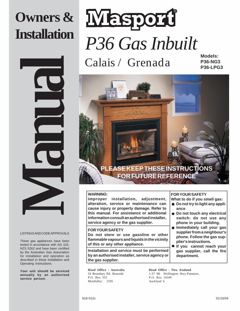
Models:P36-NG3P36-LPG3
Owners &Installation
PLEASE KEEP THESE INSTRUCTIONSFOR FUTURE REFERENCE
Man
ual
01/16/04
LISTINGS AND CODE APPROVALS
These gas appliances have beentested in accordance with AG 103,NZS 5262 and have been certifiedby the Australian Gas Associationfor installation and operation asdescribed in these Installation andOperating Instructions.
Your unit should be servicedannually by an authorisedservice person.
918-015c
WARNING:Improper installation, adjustment,alteration, service or maintenance cancause injury or property damage. Refer tothis manual. For assistance or additionalinformation consult an authorised installer,service agency or the gas supplier.
FOR YOUR SAFETYDo not store or use gasoline or otherflammable vapours and liquids in the vicinityof this or any other appliance.
Installation and service must be performedby an authorised installer, service agency orthe gas supplier.
P36 Gas Inbuilt
Head Office - Australia54 Boundary Rd. BraesideP.O. Box 553Mordialloc 3195
Head Office - New Zealand1-37 Mt Wellington Hwy.Panmure,P.O. Box 14349Auckland 6.
FOR YOUR SAFETYWhat to do if you smell gas:
Do not try to light any appli-anceDo not touch any electricalswitch: do not use anyphone in your building.Immediately call your gassupplier from a neighbour'sphone. Follow the gas sup-plier's instructions.If you cannot reach yourgas supplier, call the firedepartment.
Calais / Grenada
Masport P36-3 Gas Inbuilt2
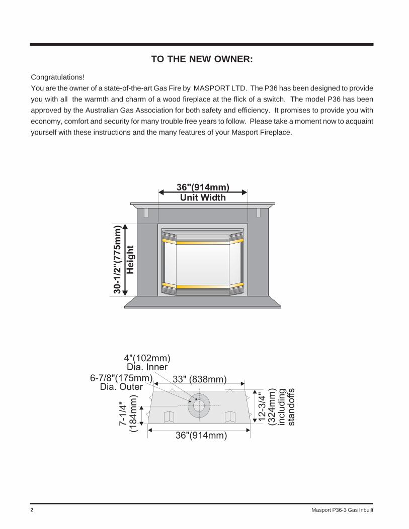
TO THE NEW OWNER:
Congratulations!
You are the owner of a state-of-the-art Gas Fire by MASPORT LTD. The P36 has been designed to provide
you with all the warmth and charm of a wood fireplace at the flick of a switch. The model P36 has been
approved by the Australian Gas Association for both safety and efficiency. It promises to provide you with
economy, comfort and security for many trouble free years to follow. Please take a moment now to acquaint
yourself with these instructions and the many features of your Masport Fireplace.
Masport P36-3 Gas Inbuilt 3
TABLE OF CONTENTS
Operating Instructions
Operating Instructions ...............................................27Lighting Procedure ....................................................27Shutdown Procedure .................................................27First Fire ...................................................................27Normal Operating Sounds of
Gas Appliances ..................................................27Lighting Plate Instructions .........................................28
Maintenance
Maintenance Instructions ..........................................28General Flue Maintenance ........................................28Gold-Plated or Brass Louvres ....................................29Gold Plated or Brass Trim .........................................29Log Replacement ......................................................29Firebox Paint .............................................................29Glass Gasket ............................................................29Door Glass ................................................................29
Flush Glass ....................................................... .29Bay Glass ..........................................................29
Removing Valve .........................................................30Installing Valve ..........................................................30
Parts List
Replacement/Spare Parts List ...................................31
Warranty
Warranty ...................................................................39
Safety Label
Safety Label ............................................................... 4
Installation
Important Message .................................................... 5Before You Start ........................................................ 5General Safety Information ......................................... 5Installation Checklist .................................................. 5Locating Your Gas Fire .............................................. 6Manufactured Home Additional Requirements ............ 6Clearances ................................................................. 6Mantel Clearances ..................................................... 7Mantel Leg Clearances............................................... 8Framing and Finishing ................................................ 8Unit Assembly Prior to Installation
Top Standoff Assembly ........................................ 9Top Facing Support & Side Nailing Strip
Assembly ...................................................... 9Flueing Introduction .................................................... 9Exterior Flue Termination Locations ..........................10Direct Flue System (Flex) .........................................11Flueing - Horizontal Terminations ..............................12Co Axial Flue System ...............................................13Vertical Terminations ................................................14Horizontal Installations ..............................................16Vertical Termination ..................................................17System Data .............................................................18Gas Line Installation..................................................18Aeration Adjustment ..................................................18Pilot Adjustment .......................................................18Pressure Testing .......................................................18S.I.T. Valve Description .............................................19Optional Brick Panels ...............................................19Log Set Installation ...................................................19Flush Door - Standard ...............................................21Optional Flush Trim ...................................................21Louvres - Flush ..........................................................21Optional Bay Door .....................................................22Optional Bay Trim .....................................................22Louvres - Bay ...........................................................22Hampton Cast Faceplate (optional) ...........................23Hampton Cast Grills (optional) ...................................24Remote Control (optional) ..........................................25Wall Thermostat (optional) ........................................25Wiring Diagram .........................................................26
Masport P36-3 Gas Inbuilt4
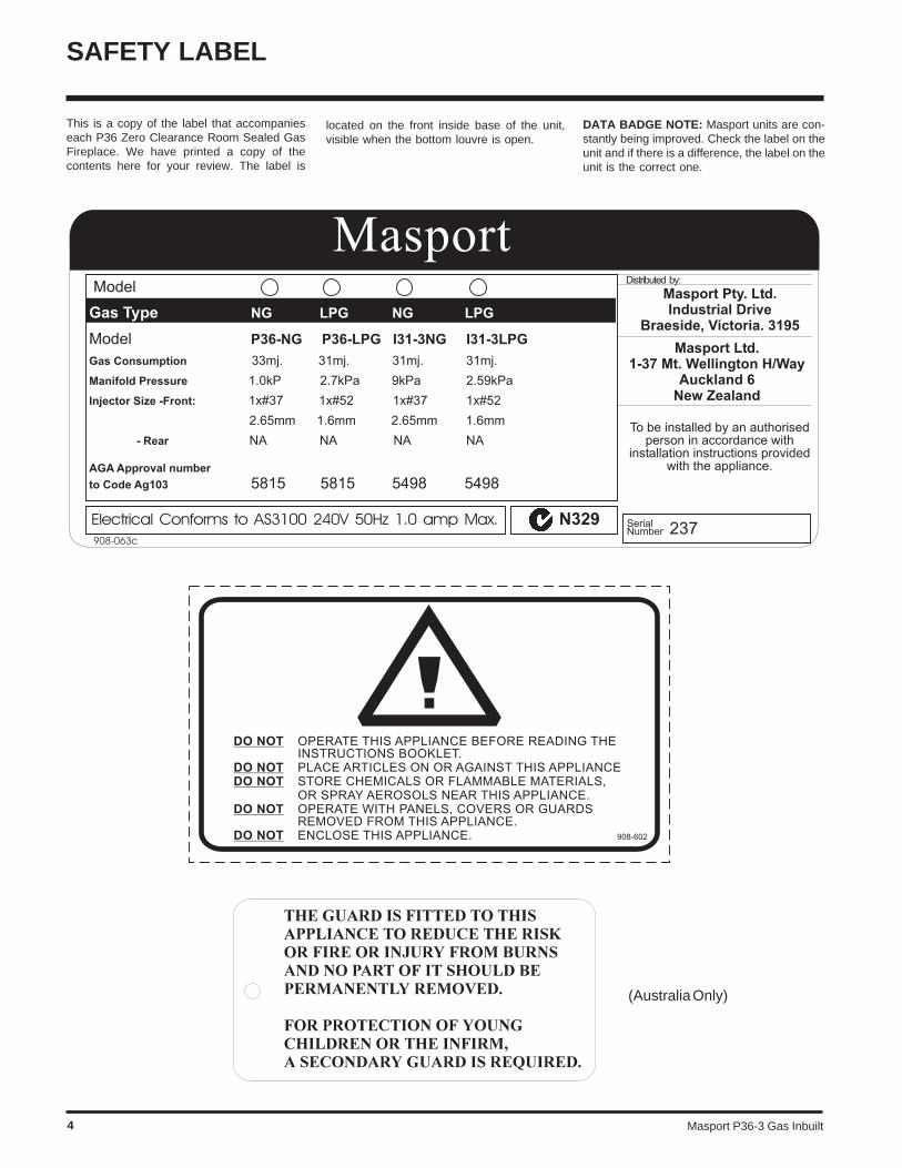
SAFETY LABEL
This is a copy of the label that accompanieseach P36 Zero Clearance Room Sealed GasFireplace. We have printed a copy of thecontents here for your review. The label is
(Australia Only)
located on the front inside base of the unit,visible when the bottom louvre is open.
DATA BADGE NOTE: Masport units are con-stantly being improved. Check the label on theunit and if there is a difference, the label on theunit is the correct one.
Masport P36-3 Gas Inbuilt 5
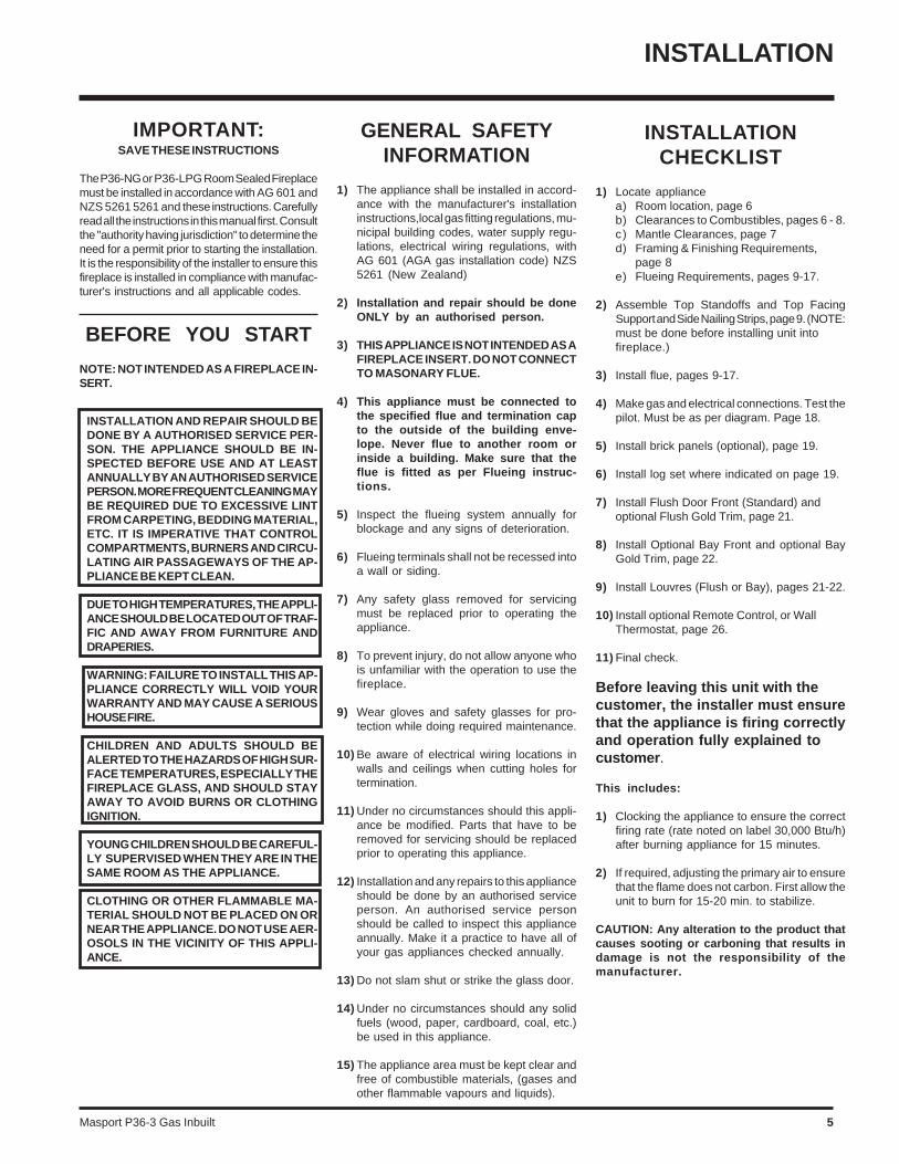
INSTALLATIONCHECKLIST
1) Locate appliancea) Room location, page 6b) Clearances to Combustibles, pages 6 - 8.c) Mantle Clearances, page 7d) Framing & Finishing Requirements,
page 8e) Flueing Requirements, pages 9-17.
2) Assemble Top Standoffs and Top FacingSupport and Side Nailing Strips, page 9. (NOTE:must be done before installing unit intofireplace.)
3) Install flue, pages 9-17.
4) Make gas and electrical connections. Test thepilot. Must be as per diagram. Page 18.
5) Install brick panels (optional), page 19.
6) Install log set where indicated on page 19.
7) Install Flush Door Front (Standard) andoptional Flush Gold Trim, page 21.
8) Install Optional Bay Front and optional BayGold Trim, page 22.
9) Install Louvres (Flush or Bay), pages 21-22.
10) Install optional Remote Control, or WallThermostat, page 26.
11) Final check.
Before leaving this unit with thecustomer, the installer must ensurethat the appliance is firing correctlyand operation fully explained tocustomer.
This includes:
1) Clocking the appliance to ensure the correctfiring rate (rate noted on label 30,000 Btu/h)after burning appliance for 15 minutes.
2) If required, adjusting the primary air to ensurethat the flame does not carbon. First allow theunit to burn for 15-20 min. to stabilize.
CAUTION: Any alteration to the product thatcauses sooting or carboning that results indamage is not the responsibility of themanufacturer.
INSTALLATION
IMPORTANT:SAVE THESE INSTRUCTIONS
The P36-NG or P36-LPG Room Sealed Fireplacemust be installed in accordance with AG 601 andNZS 5261 5261 and these instructions. Carefullyread all the instructions in this manual first. Consultthe "authority having jurisdiction" to determine theneed for a permit prior to starting the installation.It is the responsibility of the installer to ensure thisfireplace is installed in compliance with manufac-turer's instructions and all applicable codes.
BEFORE YOU START
NOTE: NOT INTENDED AS A FIREPLACE IN-SERT.
GENERAL SAFETYINFORMATION
1) The appliance shall be installed in accord-ance with the manufacturer's installationinstructions,local gas fitting regulations, mu-nicipal building codes, water supply regu-lations, electrical wiring regulations, withAG 601 (AGA gas installation code) NZS5261 (New Zealand)
2) Installation and repair should be doneONLY by an authorised person.
3) THIS APPLIANCE IS NOT INTENDED AS AFIREPLACE INSERT. DO NOT CONNECTTO MASONARY FLUE.
4) This appliance must be connected tothe specified flue and termination capto the outside of the building enve-lope. Never flue to another room orinside a building. Make sure that theflue is fitted as per Flueing instruc-tions.
5) Inspect the flueing system annually forblockage and any signs of deterioration.
6) Flueing terminals shall not be recessed intoa wall or siding.
7) Any safety glass removed for servicingmust be replaced prior to operating theappliance.
8) To prevent injury, do not allow anyone whois unfamiliar with the operation to use thefireplace.
9) Wear gloves and safety glasses for pro-tection while doing required maintenance.
10) Be aware of electrical wiring locations inwalls and ceilings when cutting holes fortermination.
11) Under no circumstances should this appli-ance be modified. Parts that have to beremoved for servicing should be replacedprior to operating this appliance.
12) Installation and any repairs to this applianceshould be done by an authorised serviceperson. An authorised service personshould be called to inspect this applianceannually. Make it a practice to have all ofyour gas appliances checked annually.
13) Do not slam shut or strike the glass door.
14) Under no circumstances should any solidfuels (wood, paper, cardboard, coal, etc.)be used in this appliance.
15) The appliance area must be kept clear andfree of combustible materials, (gases andother flammable vapours and liquids).
INSTALLATION AND REPAIR SHOULD BEDONE BY A AUTHORISED SERVICE PER-SON. THE APPLIANCE SHOULD BE IN-SPECTED BEFORE USE AND AT LEASTANNUALLY BY AN AUTHORISED SERVICEPERSON. MORE FREQUENT CLEANING MAYBE REQUIRED DUE TO EXCESSIVE LINTFROM CARPETING, BEDDING MATERIAL,ETC. IT IS IMPERATIVE THAT CONTROLCOMPARTMENTS, BURNERS AND CIRCU-LATING AIR PASSAGEWAYS OF THE AP-PLIANCE BE KEPT CLEAN.
DUE TO HIGH TEMPERATURES, THE APPLI-ANCE SHOULD BE LOCATED OUT OF TRAF-FIC AND AWAY FROM FURNITURE ANDDRAPERIES.
WARNING: FAILURE TO INSTALL THIS AP-PLIANCE CORRECTLY WILL VOID YOURWARRANTY AND MAY CAUSE A SERIOUSHOUSE FIRE.
CHILDREN AND ADULTS SHOULD BEALERTED TO THE HAZARDS OF HIGH SUR-FACE TEMPERATURES, ESPECIALLY THEFIREPLACE GLASS, AND SHOULD STAYAWAY TO AVOID BURNS OR CLOTHINGIGNITION.
YOUNG CHILDREN SHOULD BE CAREFUL-LY SUPERVISED WHEN THEY ARE IN THESAME ROOM AS THE APPLIANCE.
CLOTHING OR OTHER FLAMMABLE MA-TERIAL SHOULD NOT BE PLACED ON ORNEAR THE APPLIANCE. DO NOT USE AER-OSOLS IN THE VICINITY OF THIS APPLI-ANCE.
Masport P36-3 Gas Inbuilt6
INSTALLATION
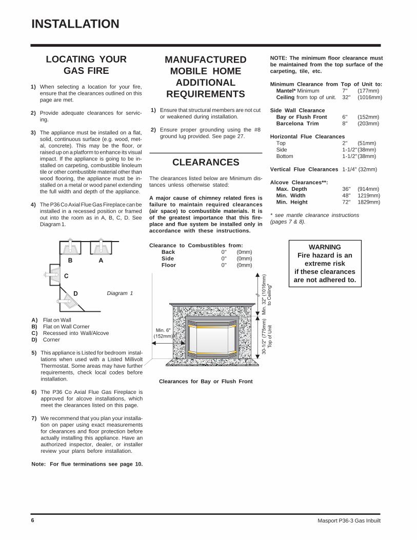
Clearances for Bay or Flush Front
NOTE: The minimum floor clearance mustbe maintained from the top surface of thecarpeting, tile, etc.
Minimum Clearance from Top of Unit to:Mantel* Minimum 7" (177mm)Ceiling from top of unit. 32" (1016mm)
Side Wall ClearanceBay or Flush Front 6" (152mm)Barcelona Trim 8" (203mm)
Horizontal Flue ClearancesTop 2" (51mm)Side 1-1/2"(38mm)Bottom 1-1/2"(38mm)
Vertical Flue Clearances 1-1/4" (32mm)
Alcove Clearances**:Max. Depth 36" (914mm)Min. Width 48" 1219mm)Min. Height 72" 1829mm)
* see mantle clearance instructions(pages 7 & 8).
CLEARANCES
The clearances listed below are Minimum dis-tances unless otherwise stated:
A major cause of chimney related fires isfailure to maintain required clearances(air space) to combustible materials. It isof the greatest importance that this fire-place and flue system be installed only inaccordance with these instructions.
Clearance to Combustibles from:Back 0" (0mm)Side 0" (0mm)Floor 0" (0mm)
Diagram 1
LOCATING YOURGAS FIRE
1) When selecting a location for your fire,ensure that the clearances outlined on thispage are met.
2) Provide adequate clearances for servic-ing.
3) The appliance must be installed on a flat,solid, continuous surface (e.g. wood, met-al, concrete). This may be the floor, orraised up on a platform to enhance its visualimpact. If the appliance is going to be in-stalled on carpeting, combustible linoleumtile or other combustible material other thanwood flooring, the appliance must be in-stalled on a metal or wood panel extendingthe full width and depth of the appliance.
4) The P36 Co Axial Flue Gas Fireplace can beinstalled in a recessed position or framedout into the room as in A, B, C, D. SeeDiagram 1.
MANUFACTUREDMOBILE HOME
ADDITIONALREQUIREMENTS
1) Ensure that structural members are not cutor weakened during installation.
2) Ensure proper grounding using the #8ground lug provided. See page 27.
A) Flat on WallB) Flat on Wall CornerC) Recessed into Wall/AlcoveD) Corner
5) This appliance is Listed for bedroom instal-lations when used with a Listed MillivoltThermostat. Some areas may have furtherrequirements, check local codes beforeinstallation.
6) The P36 Co Axial Flue Gas Fireplace isapproved for alcove installations, whichmeet the clearances listed on this page.
7) We recommend that you plan your installa-tion on paper using exact measurementsfor clearances and floor protection beforeactually installing this appliance. Have anauthorized inspector, dealer, or installerreview your plans before installation.
Note: For flue terminations see page 10.
WARNINGFire hazard is an
extreme riskif these clearancesare not adhered to.
Masport P36-3 Gas Inbuilt 7
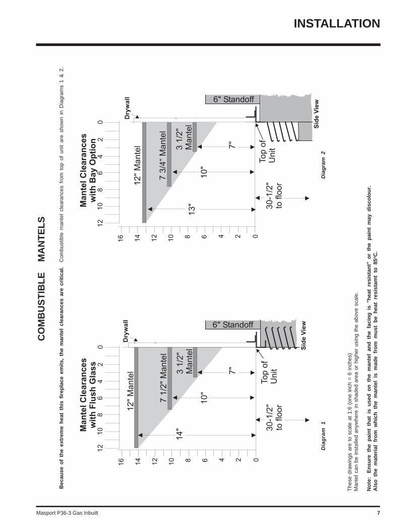
Bec
ause
of
the
extr
eme
hea
t th
is f
irep
lace
em
its,
th
e m
ante
l cl
eara
nce
s ar
e cr
itic
al.
Com
bust
ible
man
tel
clea
ranc
es f
rom
top
of
unit
are
show
n in
Dia
gram
s 1
& 2
.
CO
MB
US
TIB
LE
M
AN
TE
LS
The
se d
raw
ings
are
to
scal
e at
1:6
(on
e in
ch =
6 in
ches
)M
ante
l can
be
inst
alle
d an
ywhe
re in
sha
ded
area
or
high
er u
sing
the
abo
ve s
cale
.
No
te:
En
sure
th
e p
ain
t th
at i
s u
sed
on
th
e m
ante
l an
d t
he
faci
ng
is
"hea
t re
sist
ant"
or
the
pai
nt
may
dis
colo
ur.
Als
o t
he
mat
eria
l fr
om
wh
ich
th
e m
ante
l is
mad
e fr
om
mu
st b
e h
eat
resi
stam
t to
85o
C.
Dia
gra
m 1
Dia
gra
m 2
INSTALLATION
Masport P36-3 Gas Inbuilt8
INSTALLATION
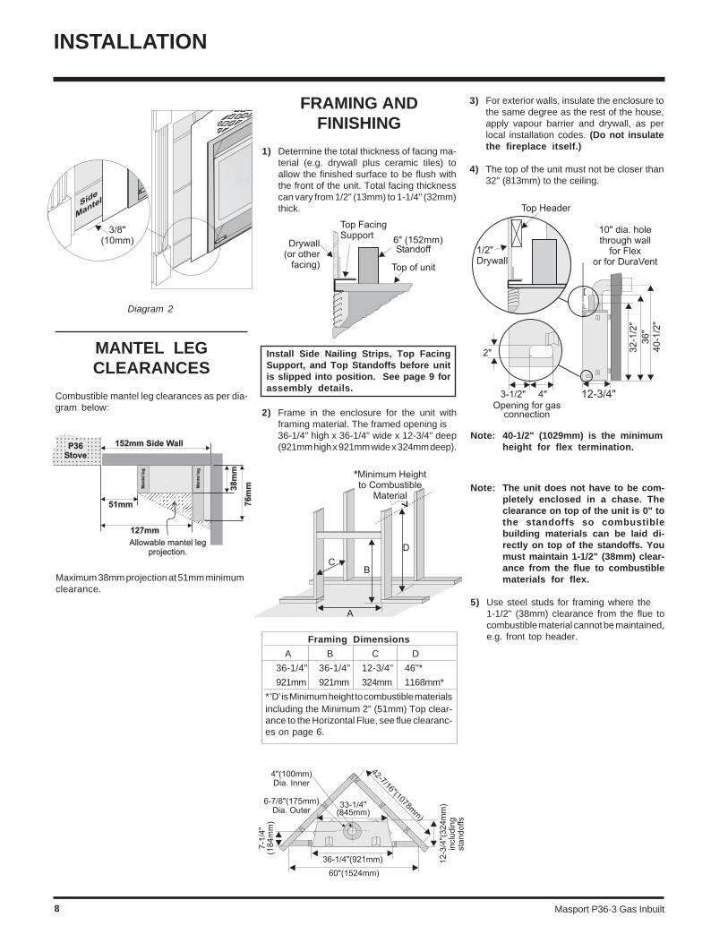
Note: 40-1/2" (1029mm) is the minimumheight for flex termination.
Note: The unit does not have to be com-pletely enclosed in a chase. Theclearance on top of the unit is 0" tothe standoffs so combustiblebuilding materials can be laid di-rectly on top of the standoffs. Youmust maintain 1-1/2" (38mm) clear-ance from the flue to combustiblematerials for flex.
5) Use steel studs for framing where the1-1/2" (38mm) clearance from the flue tocombustible material cannot be maintained,e.g. front top header.
Diagram 2
MANTEL LEGCLEARANCES
Combustible mantel leg clearances as per dia-gram below:
FRAMING ANDFINISHING
1) Determine the total thickness of facing ma-terial (e.g. drywall plus ceramic tiles) toallow the finished surface to be flush withthe front of the unit. Total facing thicknesscan vary from 1/2" (13mm) to 1-1/4" (32mm)thick.
Maximum 38mm projection at 51mm minimumclearance.
3) For exterior walls, insulate the enclosure tothe same degree as the rest of the house,apply vapour barrier and drywall, as perlocal installation codes. (Do not insulatethe fireplace itself.)
4) The top of the unit must not be closer than32" (813mm) to the ceiling.
Install Side Nailing Strips, Top FacingSupport, and Top Standoffs before unitis slipped into position. See page 9 forassembly details.
2) Frame in the enclosure for the unit withframing material. The framed opening is36-1/4" high x 36-1/4" wide x 12-3/4" deep(921mm high x 921mm wide x 324mm deep).
Framing Dimensions
A B C D
36-1/4" 36-1/4" 12-3/4" 46"*
921mm 921mm 324mm 1168mm*
* 'D' is Minimum height to combustible materialsincluding the Minimum 2" (51mm) Top clear-ance to the Horizontal Flue, see flue clearanc-es on page 6.
Masport P36-3 Gas Inbuilt 9
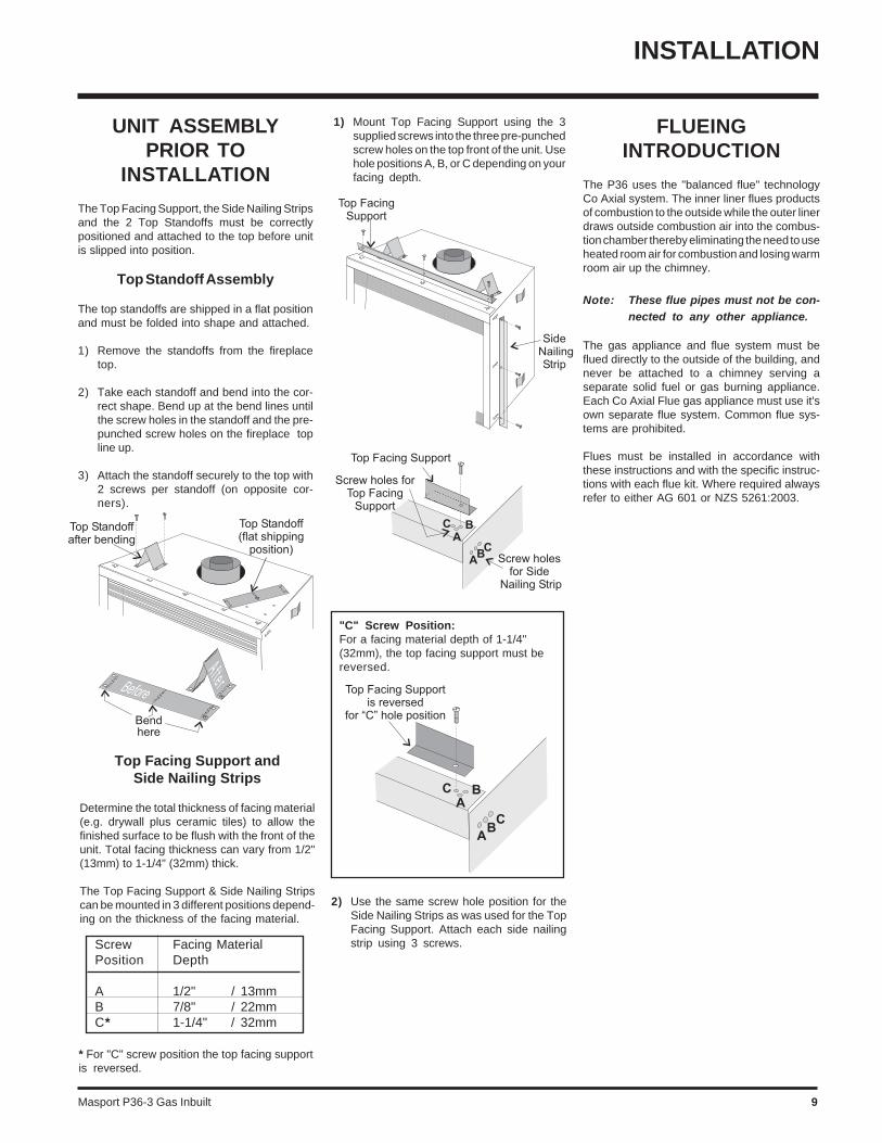
Screw Facing MaterialPosition Depth
A 1/2" / 13mmB 7/8" / 22mmC* 1-1/4" / 32mm
"C" Screw Position:For a facing material depth of 1-1/4"(32mm), the top facing support must bereversed.
UNIT ASSEMBLYPRIOR TO
INSTALLATION
The Top Facing Support, the Side Nailing Stripsand the 2 Top Standoffs must be correctlypositioned and attached to the top before unitis slipped into position.
Top Standoff Assembly
The top standoffs are shipped in a flat positionand must be folded into shape and attached.
1) Remove the standoffs from the fireplacetop.
2) Take each standoff and bend into the cor-rect shape. Bend up at the bend lines untilthe screw holes in the standoff and the pre-punched screw holes on the fireplace topline up.
3) Attach the standoff securely to the top with2 screws per standoff (on opposite cor-ners).
Top Facing Support andSide Nailing Strips
Determine the total thickness of facing material(e.g. drywall plus ceramic tiles) to allow thefinished surface to be flush with the front of theunit. Total facing thickness can vary from 1/2"(13mm) to 1-1/4" (32mm) thick.
The Top Facing Support & Side Nailing Stripscan be mounted in 3 different positions depend-ing on the thickness of the facing material.
* For "C" screw position the top facing supportis reversed.
1) Mount Top Facing Support using the 3supplied screws into the three pre-punchedscrew holes on the top front of the unit. Usehole positions A, B, or C depending on yourfacing depth.
2) Use the same screw hole position for theSide Nailing Strips as was used for the TopFacing Support. Attach each side nailingstrip using 3 screws.
FLUEINGINTRODUCTION
The P36 uses the "balanced flue" technologyCo Axial system. The inner liner flues productsof combustion to the outside while the outer linerdraws outside combustion air into the combus-tion chamber thereby eliminating the need to useheated room air for combustion and losing warmroom air up the chimney.
Note: These flue pipes must not be con-nected to any other appliance.
The gas appliance and flue system must beflued directly to the outside of the building, andnever be attached to a chimney serving aseparate solid fuel or gas burning appliance.Each Co Axial Flue gas appliance must use it'sown separate flue system. Common flue sys-tems are prohibited.
Flues must be installed in accordance withthese instructions and with the specific instruc-tions with each flue kit. Where required alwaysrefer to either AG 601 or NZS 5261:2003.
INSTALLATION

Masport P36-3 Gas Inbuilt10
INSTALLATION
EXTERIOR FLUE TERMINATION LOCATIONS
Minimum clearances required for balanced flue terminalsor the flue terminals of outdoor appliances according
to AG 601 (AGA gas installation code) or NZS 5261 (New Zealand).For vertical termination height refer to AG 601 or NZS 5261.
MinimumClearance (mm)
a Below eaves, balconies or other projections:- Appliances up to 50 MJ/h input 300- Appliances over 50 MJ/h input 500
b From the ground or above a balcony 300c From a return wall or external corner 500d From a gas meter (M) 1000e From an electricity meter or fuse box (P) 500f From a drain or soil pipe 150g Horizontal from any building structure (unless appliance is approved
for closer installation) or obstruction facing a terminal 500h From any other flue terminal, cowl or combustion air intake 500j Horizontally from an openable window, door, or non-mechanical air inlet, or
any other opening into a building, with the exception of sub-floor ventilation(see also Note (I)):- Appliances up to 150 MJ/h input 500- Appliances over 150 MJ/h input 1500
k Vertically below an openable window, door, or non-mechanical air inlet,or any other opening into a building, with the exception of sub-floor ventilation(see also Note (I)): see table below
Clearance 'k' in mm
Space Heaters All Other AppliancesUp to 50 MJ/h Up to 50 MJ/h input Over 50 MJ/h input Over 150 MJ/h input input to 150 MJ/h input
150 500 1000 1500
NOTES:(I) For mechanical air inlets, including spa blowers, the clearance 'j' and 'k' shall be 1500 mm in all cases.(II) All distances shall be measured vertically or horizontally along the wall to a point in line with the nearest
par to of the terminal.(III) Prohibited area below electricity meter or fuse box extends to ground level.(IV)A flue terminal of this type shall not be located under a roofed area unless the roofed area is fully open on
at least two sides and a free flow of air at the appliance is achieved.

Masport P36-3 Gas Inbuilt 11
FLUEING
Direct Flue System (Flex)Horizontal Terminations Only
These flueing systems, in combination with the P36 Room Sealed Gas Fireplace, have been tested and listed as a Direct Vent type flue systemby the Australian Gas Association. The location of the termination cap must conform to the requirements in the Flue Terminal Locations diagramon page 10.
Direct Flue (Flex) System Termination Kit (Part # 946-515) includes all the parts needed to install the P36 with a maximum run of1.2m.
1) 175mm dia. flexible liner (1200mm length)2) 100mm dia. flexible liner (1200mm length)3) spring spacers (4)4) thimble (2)5) AstroCap termination cap (1)6) screws (12)7) tube of Mill Pac (1)8) plated screws (8)9) screws #8 x 1-1/2" Drill Point, Stainless Steel (4)
If longer runs are needed, the Direct Fluesystem (Flex) # 946-516 includes all the partsneeded to install the P36 with a maximum 3.0mrun.
1) 175mm dia. flexible liner (3.0m length)2) 100mm dia. flexible liner (3.0m length)3) spring spacers (7)4) thimble (2)5) AstroCap termination cap (1)6) screws (12)7) tube of Mill Pac (1)8) plated screws (8)9) screws #8 x 1-1/2" Drill Point, Stainless Steel (4)
Notes:1) Liner sections should be continuous without any joints or seams.
2) Only Flex pipe purchased from Masport may be used for Flex installations.
3) If you are installing the P36 into a Masport Mantel Kit, use the minimum horizontal vent height (centre-line of 1029mm).Remember to include the mantel base in your calculations and to maintain the 32mm clearance (38mm with Flex) to theunderside of the mantel top.
INSTALLATION
Masport P36-3 Gas Inbuilt12
INSTALLATION
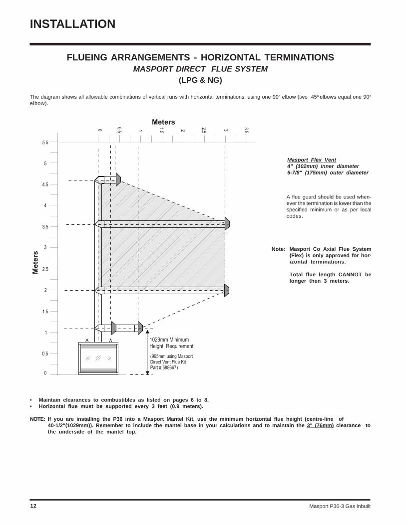
FLUEING ARRANGEMENTS - HORIZONTAL TERMINATIONSMASPORT DIRECT FLUE SYSTEM
(LPG & NG)
The diagram shows all allowable combinations of vertical runs with horizontal terminations, using one 90o elbow (two 45o elbows equal one 90o
elbow).
Masport Flex Vent4" (102mm) inner diameter6-7/8" (175mm) outer diameter
• Maintain clearances to combustibles as listed on pages 6 to 8.• Horizontal flue must be supported every 3 feet (0.9 meters).
NOTE: If you are installing the P36 into a Masport Mantel Kit, use the minimum horizontal flue height (centre-line of40-1/2"(1029mm)). Remember to include the mantel base in your calculations and to maintain the 3" (76mm) clearance tothe underside of the mantel top.
A flue guard should be used when-ever the termination is lower than thespecified minimum or as per localcodes.
Note: Masport Co Axial Flue System(Flex) is only approved for hor-izontal terminations.
Total flue length CANNOT belonger then 3 meters.
Masport P36-3 Gas Inbuilt 13
INSTALLATION
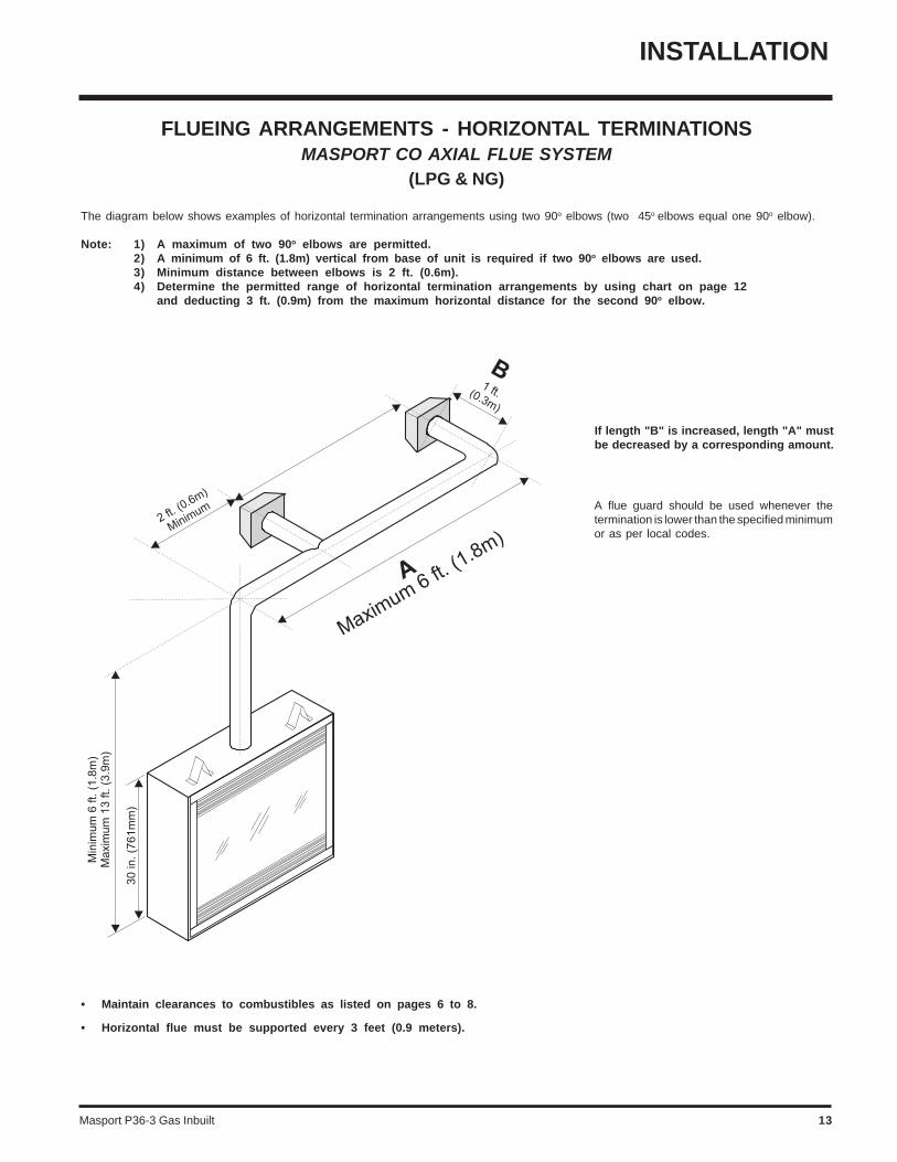
FLUEING ARRANGEMENTS - HORIZONTAL TERMINATIONSMASPORT CO AXIAL FLUE SYSTEM
(LPG & NG)
The diagram below shows examples of horizontal termination arrangements using two 90o elbows (two 45o elbows equal one 90o elbow).
Note: 1) A maximum of two 90o elbows are permitted.2) A minimum of 6 ft. (1.8m) vertical from base of unit is required if two 90o elbows are used.3) Minimum distance between elbows is 2 ft. (0.6m).4) Determine the permitted range of horizontal termination arrangements by using chart on page 12
and deducting 3 ft. (0.9m) from the maximum horizontal distance for the second 90o elbow.
• Maintain clearances to combustibles as listed on pages 6 to 8.
• Horizontal flue must be supported every 3 feet (0.9 meters).
A flue guard should be used whenever thetermination is lower than the specified minimumor as per local codes.
If length "B" is increased, length "A" mustbe decreased by a corresponding amount.
Masport P36-3 Gas Inbuilt14
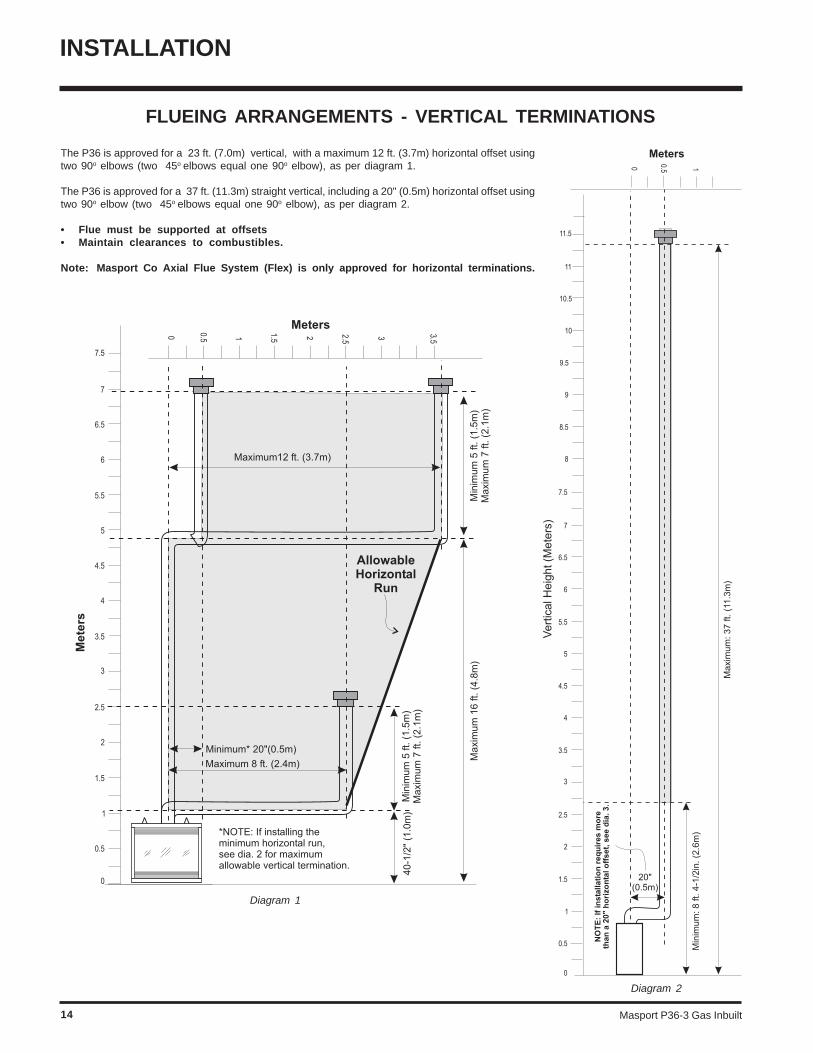
FLUEING ARRANGEMENTS - VERTICAL TERMINATIONS
The P36 is approved for a 23 ft. (7.0m) vertical, with a maximum 12 ft. (3.7m) horizontal offset usingtwo 90o elbows (two 45o elbows equal one 90o elbow), as per diagram 1.
The P36 is approved for a 37 ft. (11.3m) straight vertical, including a 20" (0.5m) horizontal offset usingtwo 90o elbow (two 45o elbows equal one 90o elbow), as per diagram 2.
• Flue must be supported at offsets• Maintain clearances to combustibles.
Note: Masport Co Axial Flue System (Flex) is only approved for horizontal terminations.
Diagram 1
Diagram 2
INSTALLATION
Masport P36-3 Gas Inbuilt 15
INSTALLATION
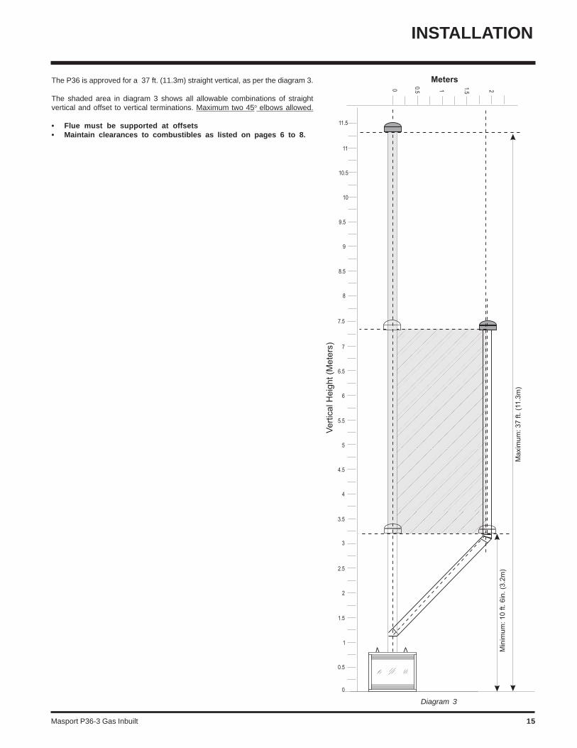
The P36 is approved for a 37 ft. (11.3m) straight vertical, as per the diagram 3.
The shaded area in diagram 3 shows all allowable combinations of straightvertical and offset to vertical terminations. Maximum two 45o elbows allowed.
• Flue must be supported at offsets• Maintain clearances to combustibles as listed on pages 6 to 8.
Diagram 3
Masport P36-3 Gas Inbuilt16
Diagram 3
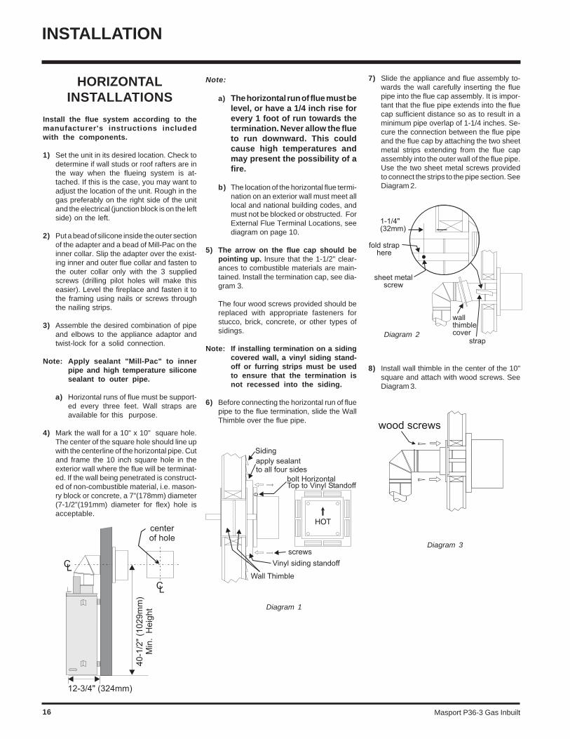
HORIZONTALINSTALLATIONS
Install the flue system according to themanufacturer's instructions includedwith the components.
1) Set the unit in its desired location. Check todetermine if wall studs or roof rafters are inthe way when the flueing system is at-tached. If this is the case, you may want toadjust the location of the unit. Rough in thegas preferably on the right side of the unitand the electrical (junction block is on the leftside) on the left.
2) Put a bead of silicone inside the outer sectionof the adapter and a bead of Mill-Pac on theinner collar. Slip the adapter over the exist-ing inner and outer flue collar and fasten tothe outer collar only with the 3 suppliedscrews (drilling pilot holes will make thiseasier). Level the fireplace and fasten it tothe framing using nails or screws throughthe nailing strips.
3) Assemble the desired combination of pipeand elbows to the appliance adaptor andtwist-lock for a solid connection.
Note: Apply sealant "Mill-Pac" to innerpipe and high temperature siliconesealant to outer pipe.
a) Horizontal runs of flue must be support-ed every three feet. Wall straps areavailable for this purpose.
4) Mark the wall for a 10" x 10" square hole.The center of the square hole should line upwith the centerline of the horizontal pipe. Cutand frame the 10 inch square hole in theexterior wall where the flue will be terminat-ed. If the wall being penetrated is construct-ed of non-combustible material, i.e. mason-ry block or concrete, a 7"(178mm) diameter(7-1/2"(191mm) diameter for flex) hole isacceptable.
Note:
a) The horizontal run of flue must belevel, or have a 1/4 inch rise forevery 1 foot of run towards thetermination. Never allow the flueto run downward. This couldcause high temperatures andmay present the possibility of afire.
b) The location of the horizontal flue termi-nation on an exterior wall must meet alllocal and national building codes, andmust not be blocked or obstructed. ForExternal Flue Terminal Locations, seediagram on page 10.
5) The arrow on the flue cap should bepointing up. Insure that the 1-1/2" clear-ances to combustible materials are main-tained. Install the termination cap, see dia-gram 3.
The four wood screws provided should bereplaced with appropriate fasteners forstucco, brick, concrete, or other types ofsidings.
Note: If installing termination on a sidingcovered wall, a vinyl siding stand-off or furring strips must be usedto ensure that the termination isnot recessed into the siding.
6) Before connecting the horizontal run of fluepipe to the flue termination, slide the WallThimble over the flue pipe.
Diagram 1
INSTALLATION
7) Slide the appliance and flue assembly to-wards the wall carefully inserting the fluepipe into the flue cap assembly. It is impor-tant that the flue pipe extends into the fluecap sufficient distance so as to result in aminimum pipe overlap of 1-1/4 inches. Se-cure the connection between the flue pipeand the flue cap by attaching the two sheetmetal strips extending from the flue capassembly into the outer wall of the flue pipe.Use the two sheet metal screws providedto connect the strips to the pipe section. SeeDiagram 2.
8) Install wall thimble in the center of the 10"square and attach with wood screws. SeeDiagram 3.
Diagram 2
Masport P36-3 Gas Inbuilt 17
INSTALLATION
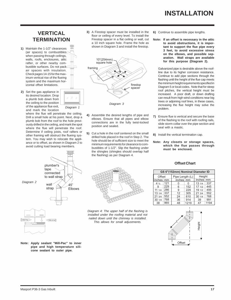
Offset Chart
7) Ensure flue is vertical and secure the baseof the flashing to the roof with roofing rails,slide storm collar over the pipe section andseal with a mastic.
8) Install the vertical termination cap.
Note: Any closets or storage spaces,which the flue passes throughmust be enclosed.
Diagram 3Diagram 1
Diagram 2
Note: Apply sealant "Mill-Pac" to innerpipe and high temperature sili-cone sealant to outer pipe.
VERTICALTERMINATION
1) Maintain the 1-1/2" clearances(air spaces) to combustibleswhen passing through ceilings,walls, roofs, enclosures, atticrafter, or other nearby com-bustible surfaces. Do not packair spaces with insulation.Check pages 14-15 for the max-imum vertical rise of the flueingsystem and the maximum hor-izontal offset limitations.
2) Set the gas appliance inits desired location. Dropa plumb bob down fromthe ceiling to the positionof the appliance flue exit,and mark the locationwhere the flue will penetrate the ceiling.Drill a small hole at his point. Next, drop aplumb bob from the roof to the hole previ-ously drilled in the ceiling, and mark the spotwhere the flue will penetrate the roof.Determine if ceiling joists, roof rafters orother framing will obstruct the flueing sys-tem. You may wish to relocate the appli-ance or to offset, as shown in Diagram 2 toavoid cutting load bearing members.
3) A Firestop spacer must be installed in thefloor or ceiling of every level. To install theFirestop spacer in a flat ceiling or wall, cuta 10 inch square hole. Frame the hole asshown in Diagram 3 and install the firestop.
4) Assemble the desired lengths of pipe andelbows. Ensure that all pipes and elbowconnections are in the fully twist-lockedposition and sealed.
5) Cut a hole in the roof centered on the smalldrilled hole placed in the roof in Step 2. Thehole should be of sufficient size to meet theminimum requirements for clearance to com-bustibles of 1-1/2". Slip the flashing underthe shingles (shingles should overlap halfthe flashing) as per Diagram 4.
Diagram 4: The upper half of the flashing isinstalled under the roofing material and notnailed down until the chimney is installed.
This allows for small adjustments.
6) Continue to assemble pipe lengths.
Note: If an offset is necessary in the atticto avoid obstructions, it is impor-tant to support the flue pipe every3 feet, to avoid excessive stresson the elbows, and possible sep-aration. Wall straps are availablefor this purpose (Diagram 2).
Galvanized pipe is desirable above the roof-line due to its higher corrosion resistance.Continue to add pipe sections through theflashing until the height of the flue cap meetsthe minimum height requirements specified inDiagram 5 or local codes. Note that for steeproof pitches, the vertical height must beincreased. A poor draft, or down draftingcan result from high wind conditions near bigtrees or adjoining roof lines, in these cases,increasing the flue height may solve theproblem.
Masport P36-3 Gas Inbuilt18
INSTALLATION
PRESSURE TESTING
The manifold pressure is controlled by a regu-lator built into the gas control, and should bechecked at the pressure test point.
Note: To properly check gas pressure,both inlet and manifold pressuresshould be checked using the valvepressure ports on the valve.
1) Make sure the valve is in the "OFF" position.
2) Loosen the "IN" and/or "OUT" pressuretap(s), turning counterclockwise with a1/8" wide flat screwdriver.
3) Attach manometer to "IN" and/or "OUT"pressure tap(s) using a 5/16" ID hose.
4) Light the pilot and turn the valve to "ON"position.
5) The pressure check should be carried outwith the unit burning and the setting shouldbe within the limits specified on the safetylabel.
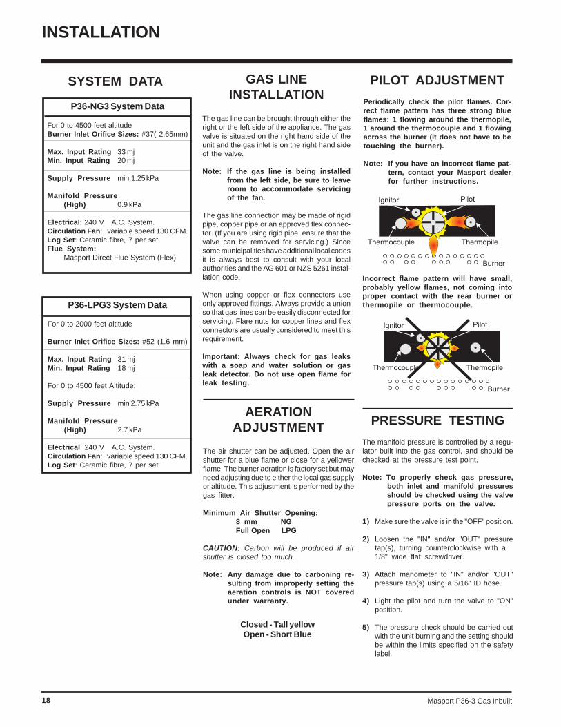
P36-NG3 System Data
For 0 to 4500 feet altitudeBurner Inlet Orifice Sizes: #37( 2.65mm)
Max. Input Rating 33 mjMin. Input Rating 20 mj
Supply Pressure min.1.25 kPa
Manifold Pressure(High) 0.9 kPa
Electrical: 240 V A.C. System.Circulation Fan: variable speed 130 CFM.Log Set: Ceramic fibre, 7 per set.Flue System:
Masport Direct Flue System (Flex)
P36-LPG3 System Data
For 0 to 2000 feet altitude
Burner Inlet Orifice Sizes: #52 (1.6 mm)
Max. Input Rating 31 mjMin. Input Rating 18 mj
For 0 to 4500 feet Altitude:
Supply Pressure min 2.75 kPa
Manifold Pressure(High) 2.7 kPa
Electrical: 240 V A.C. System.Circulation Fan: variable speed 130 CFM.Log Set: Ceramic fibre, 7 per set.
PILOT ADJUSTMENT
Periodically check the pilot flames. Cor-rect flame pattern has three strong blueflames: 1 flowing around the thermopile,1 around the thermocouple and 1 flowingacross the burner (it does not have to betouching the burner).
Note: If you have an incorrect flame pat-tern, contact your Masport dealerfor further instructions.
Incorrect flame pattern will have small,probably yellow flames, not coming intoproper contact with the rear burner orthermopile or thermocouple.
AERATIONADJUSTMENT
The air shutter can be adjusted. Open the airshutter for a blue flame or close for a yellowerflame. The burner aeration is factory set but mayneed adjusting due to either the local gas supplyor altitude. This adjustment is performed by thegas fitter.
Minimum Air Shutter Opening:8 mm NGFull Open LPG
CAUTION: Carbon will be produced if airshutter is closed too much.
Note: Any damage due to carboning re-sulting from improperly setting theaeration controls is NOT coveredunder warranty.
Closed - Tall yellowOpen - Short Blue
GAS LINEINSTALLATION
The gas line can be brought through either theright or the left side of the appliance. The gasvalve is situated on the right hand side of theunit and the gas inlet is on the right hand sideof the valve.
Note: If the gas line is being installedfrom the left side, be sure to leaveroom to accommodate servicingof the fan.
The gas line connection may be made of rigidpipe, copper pipe or an approved flex connec-tor. (If you are using rigid pipe, ensure that thevalve can be removed for servicing.) Sincesome municipalities have additional local codesit is always best to consult with your localauthorities and the AG 601 or NZS 5261 instal-lation code.
When using copper or flex connectors useonly approved fittings. Always provide a unionso that gas lines can be easily disconnected forservicing. Flare nuts for copper lines and flexconnectors are usually considered to meet thisrequirement.
Important: Always check for gas leakswith a soap and water solution or gasleak detector. Do not use open flame forleak testing.
SYSTEM DATA
Masport P36-3 Gas Inbuilt 19
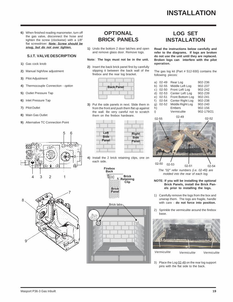
OPTIONALBRICK PANELS
1) Undo the bottom 2 door latches and openand remove glass door. Remove logs.
Note: The logs must not be in the unit.
2) Insert the back brick panel first by carefullyslipping it between the back wall of thefirebox and the rear log bracket.
6) When finished reading manometer, turn offthe gas valve, disconnect the hose andtighten the screw (clockwise) with a 1/8"flat screwdriver. Note: Screw should besnug, but do not over tighten.
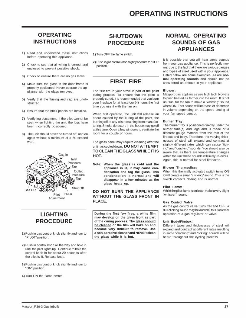
S.I.T. VALVE DESCRIPTION
1) Gas cock knob
2) Manual high/low adjustment
3) Pilot Adjustment
4) Thermocouple Connection - option
5) Outlet Pressure Tap
6) Inlet Pressure Tap
7) Pilot Outlet
8) Main Gas Outlet
9) Alternative TC Connection Point
3) Put the side panels in next. Slide them infrom the front and push them flat up againstthe wall. Be very careful not to scratchthem on the firebox hardware.
4) Install the 2 brick retaining clips, one oneach side.
INSTALLATION
LOG SETINSTALLATION
Read the instructions below carefully andrefer to the diagrams. If logs are brokendo not use the unit until they are replaced.Broken logs can interfere with the pilotoperation.
The gas log kit (Part # 512-930) contains thefollowing pieces:
a) 02-49 Rear Log 902-236b) 02-55 Middle Left Log 902-237c) 02-50 Front Left Log 902-242d) 02-53 Center Left Log 902-239e) 02-51 Front Bottom Log 902-241f ) 02-54 Center Right Log 902-238g) 02-52 Middle Right Log 902-240h) Embers 902-156i) Vermiculite 902-179/21
NOTE: If you will be installing the optionalBrick Panels, install the Brick Pan-els prior to installing the logs.
1) Carefully remove the logs from the box andunwrap them. The logs are fragile, handlewith care - do not force into position.
2) Sprinkle the vermiculite around the fireboxbase.
Vermiculite Vermiculite Vermiculite
The "02" refer numbers (i.e. 02-49) aremolded into the rear of each log.
3) Place the Log 02-49 on the rear log supportpins with the flat side to the back.
Masport P36-3 Gas Inbuilt20
INSTALLATION
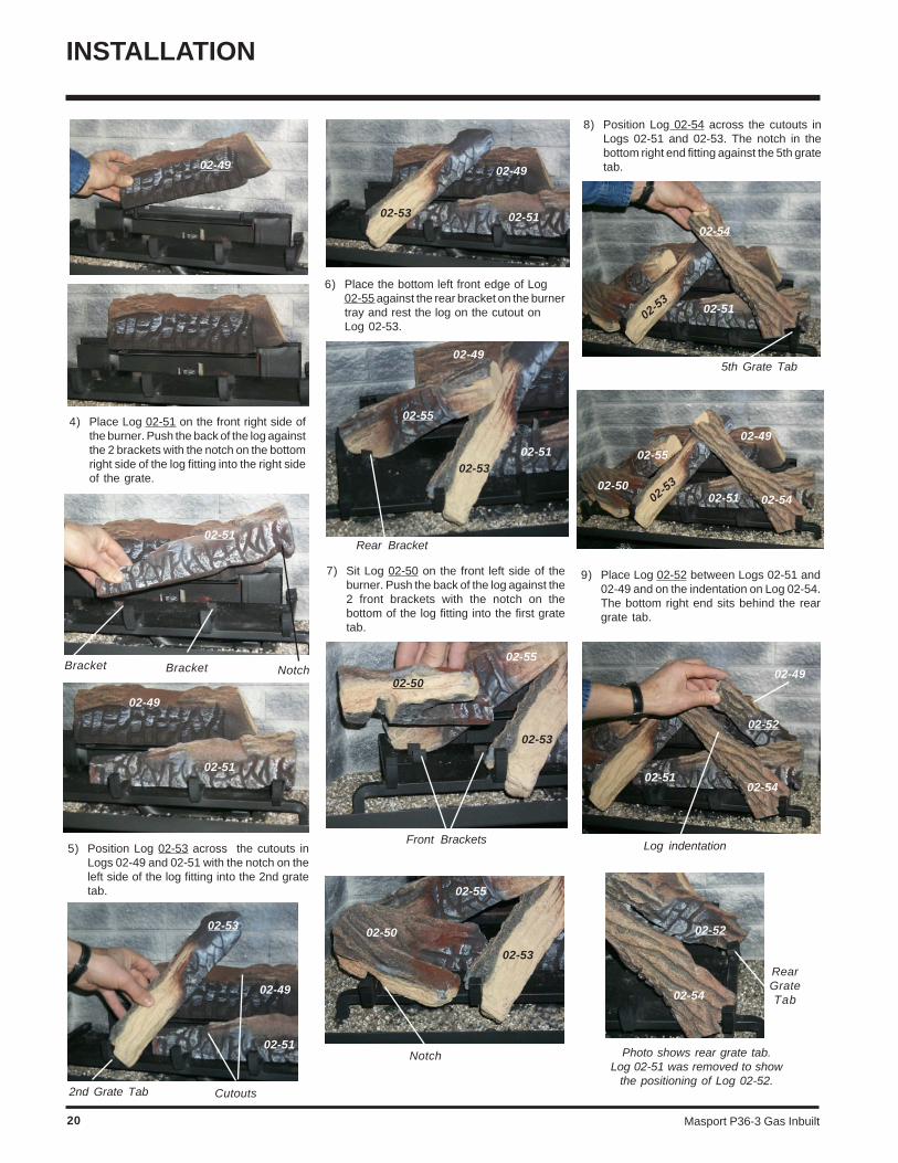
9) Place Log 02-52 between Logs 02-51 and02-49 and on the indentation on Log 02-54.The bottom right end sits behind the reargrate tab.
Log indentation
Photo shows rear grate tab.Log 02-51 was removed to show
the positioning of Log 02-52.
RearGrateTab
02-52
02-49
02-5102-54
02-52
02-54
5th Grate Tab
Rear Bracket
Front Brackets
Notch
02-55
02-50
02-54
5) Position Log 02-53 across the cutouts inLogs 02-49 and 02-51 with the notch on theleft side of the log fitting into the 2nd gratetab.
Cutouts2nd Grate Tab
02-53
02-49
02-51
02-49
02-5102-53
02-49
02-5102-53
02-55
02-53
02-50
02-55
02-53
02-50
02-55
02-53
02-49
02-51
02-5302-51 02-54
NotchBracketBracket
02-49
02-51
02-49
02-51
4) Place Log 02-51 on the front right side ofthe burner. Push the back of the log againstthe 2 brackets with the notch on the bottomright side of the log fitting into the right sideof the grate.
6) Place the bottom left front edge of Log02-55 against the rear bracket on the burnertray and rest the log on the cutout onLog 02-53.
7) Sit Log 02-50 on the front left side of theburner. Push the back of the log against the2 front brackets with the notch on thebottom of the log fitting into the first gratetab.
8) Position Log 02-54 across the cutouts inLogs 02-51 and 02-53. The notch in thebottom right end fitting against the 5th gratetab.
Masport P36-3 Gas Inbuilt 21
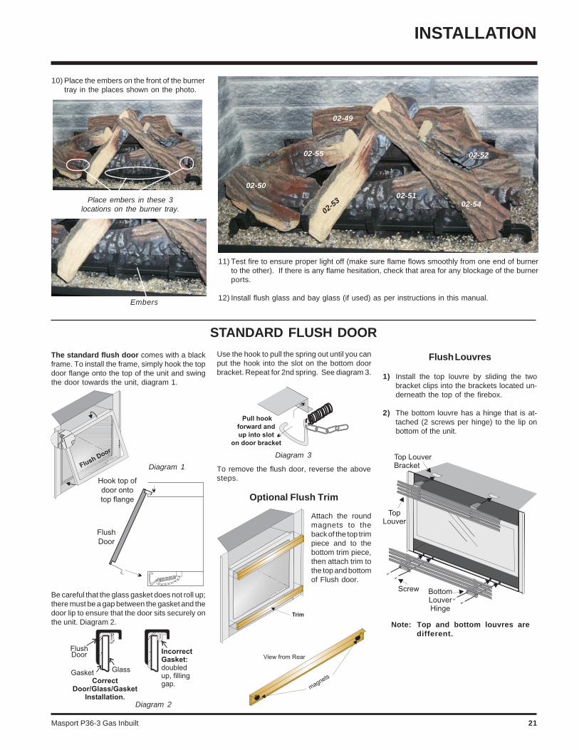
STANDARD FLUSH DOOR
Diagram 3
Use the hook to pull the spring out until you canput the hook into the slot on the bottom doorbracket. Repeat for 2nd spring. See diagram 3.
Diagram 2
The standard flush door comes with a blackframe. To install the frame, simply hook the topdoor flange onto the top of the unit and swingthe door towards the unit, diagram 1.
Be careful that the glass gasket does not roll up;there must be a gap between the gasket and thedoor lip to ensure that the door sits securely onthe unit. Diagram 2.
Diagram 1 To remove the flush door, reverse the abovesteps.
Optional Flush Trim
Attach the roundmagnets to theback of the top trimpiece and to thebottom trim piece,then attach trim tothe top and bottomof Flush door.
Flush Louvres
1) Install the top louvre by sliding the twobracket clips into the brackets located un-derneath the top of the firebox.
2) The bottom louvre has a hinge that is at-tached (2 screws per hinge) to the lip onbottom of the unit.
Note: Top and bottom louvres aredifferent.
INSTALLATION
10) Place the embers on the front of the burnertray in the places shown on the photo.
11) Test fire to ensure proper light off (make sure flame flows smoothly from one end of burnerto the other). If there is any flame hesitation, check that area for any blockage of the burnerports.
12) Install flush glass and bay glass (if used) as per instructions in this manual.
Place embers in these 3locations on the burner tray.
Embers
02-50
02-55
02-49
02-5302-51
02-54
02-52

Masport P36-3 Gas Inbuilt22
INSTALLATION
Bay Louvres
1) Install top louvre by sliding the two bracketclips into the brackets located on top of thebay door. See below. The fitted louvreleaves a small gap between faceplate bot-tom and louvre top.
2) Install bottom louvre by sliding the twobracket clips into the brackets located un-derneath the bay door. Secure with 1screw into each Bottom Louvre MountingBracket as per diagram below. Use thebottom hole in the bracket.
OPTIONAL BAY DOOR
The Bay louvres MUST be usedwith the Bay glass option.
The optional Bay door is an overlay on theflush front. The standard flush door and glassmust remain on the unit.
1) Hook the top of the bay door over the flushdoor flange and swing the bottom againstthe bottom flange of the flush door.
2) Secure to the flush door bottom bracket with2 screws provided.
3) Slide the valve extension knobs onto thevalve knobs.
Note: If any maintenance etc. must bedone in the firebox, first removethe Bay louvres and door.
Optional Bay Trim
Attach 4 supplied magnets each to the backof the top and bottom trim pieces, and attachtrim to the top and bottom of Bay door.
3) Slide the valve extension knobs onto thevalve knobs. Match the correct ext. knobwith the valve knob.
Masport P36-3 Gas Inbuilt 23
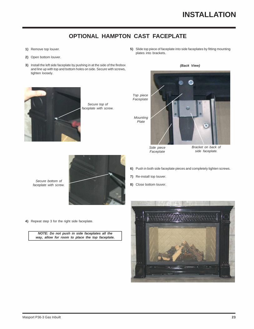
OPTIONAL HAMPTON CAST FACEPLATE
1) Remove top louver.
2) Open bottom louver.
3) Install the left side faceplate by pushing in at the side of the fireboxand line up with top and bottom holes on side. Secure with screws,tighten loosely.
Secure top offaceplate with screw.
4) Repeat step 3 for the right side faceplate.
Secure bottom offaceplate with screw.
5) Slide top piece of faceplate into side faceplates by fitting mountingplates into brackets.
6) Push in both side faceplate pieces and completely tighten screws.
7) Re-install top louver.
8) Close bottom louver.
Side pieceFaceplate
(Back View)
Bracket on back ofside faceplate.
Top pieceFaceplate
NOTE: Do not push in side faceplates all theway, allow for room to place the top faceplate.
MountingPlate
INSTALLATION
Masport P36-3 Gas Inbuilt24
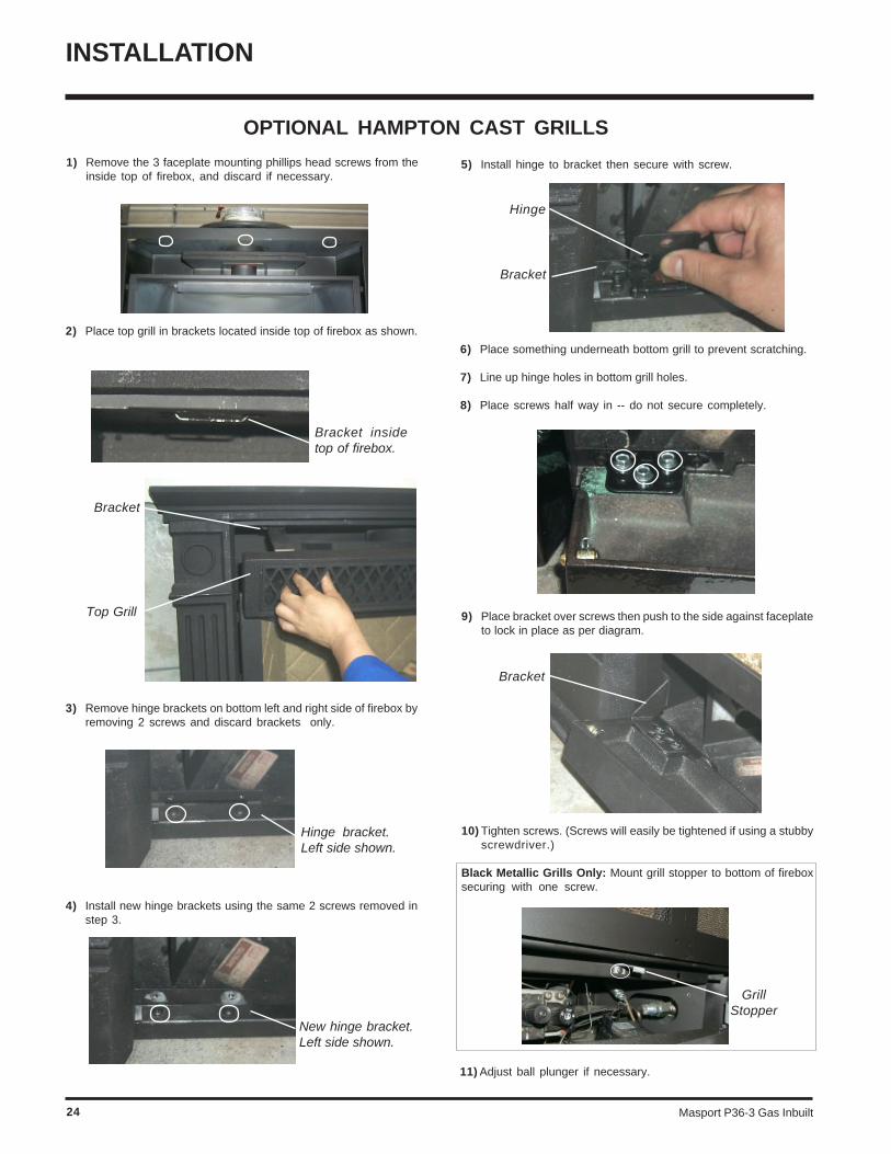
1) Remove the 3 faceplate mounting phillips head screws from theinside top of firebox, and discard if necessary.
2) Place top grill in brackets located inside top of firebox as shown.
3) Remove hinge brackets on bottom left and right side of firebox byremoving 2 screws and discard brackets only.
Bracket insidetop of firebox.
Hinge bracket.Left side shown.
4) Install new hinge brackets using the same 2 screws removed instep 3.
5) Install hinge to bracket then secure with screw.
New hinge bracket.Left side shown.
6) Place something underneath bottom grill to prevent scratching.
7) Line up hinge holes in bottom grill holes.
8) Place screws half way in -- do not secure completely.
Hinge
9) Place bracket over screws then push to the side against faceplateto lock in place as per diagram.
10) Tighten screws. (Screws will easily be tightened if using a stubbyscrewdriver.)
Black Metallic Grills Only: Mount grill stopper to bottom of fireboxsecuring with one screw.
Bracket
Bracket
Top Grill
Bracket
GrillStopper
OPTIONAL HAMPTON CAST GRILLS
11) Adjust ball plunger if necessary.
INSTALLATION
Masport P36-3 Gas Inbuilt 25
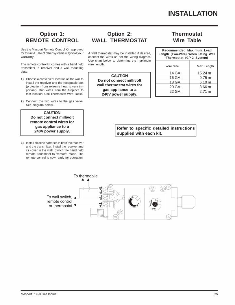
Option 2:WALL THERMOSTAT
A wall thermostat may be installed if desired,connect the wires as per the wiring diagram.Use chart below to determine the maximumwire length.
CAUTIONDo not connect millivoltwall thermostat wires for
gas appliance to a240V power supply.
Option 1:REMOTE CONTROL
Use the Masport Remote Control Kit approvedfor this unit. Use of other systems may void yourwarranty.
The remote control kit comes with a hand heldtransmitter, a receiver and a wall mountingplate.
1) Choose a convenient location on the wall toinstall the receiver and the receptacle box(protection from extreme heat is very im-portant). Run wires from the fireplace tothat location. Use Thermostat Wire Table.
2) Connect the two wires to the gas valve.See diagram below.
CAUTIONDo not connect millivoltremote control wires for
gas appliance to a240V power supply.
3) Install alkaline batteries in both the receiverand the transmitter. Install the receiver andits cover in the wall. Switch the hand heldremote transmitter to "remote" mode. Theremote control is now ready for operation.
ThermostatWire Table
14 GA.16 GA.18 GA.20 GA.22 GA.
15.24 m9.75 m6.10 m3.66 m2.71 m
Recommended Maximum LeadLength (Two-Wire) When Using Wall
Thermostat (CP-2 System)
Wire Size Max. Length
INSTALLATION
Refer to specific detailed instructionssupplied with each kit.

Masport P36-3 Gas Inbuilt26
INSTALLATION
WIRING
CAUTION: Label all wires prior todisconnection when servicing con-trols. Wiring errors can cause im-proper and dangerous operation.
This heater does not require a 240V A.C. supplyfor the gas control to operate. A 240V A.C.power supply is needed for the fan/bloweroperation.
Caution: Ensure that the wires donot touch any hot surfaces and areaway from sharp edges.
WARNING: Electrical Grounding InstructionsThis appliance is equipped with a three pronged (grounding) plug for yourprotection against shock hazard and should be plugged directly into a properlygrounded three-prong receptacle. Do not cut or remove the grounding prongfrom this plug.
NOTE: Switch must bein "OFF" position tooperate remote.
Masport P36-3 Gas Inbuilt 27
SHUTDOWNPROCEDURE
1) Turn OFF the flame switch.
2) Push in gas control knob slightly and turn to "OFF"position.
FIRST FIRE
The first fire in your stove is part of the paintcuring process. To ensure that the paint isproperly cured, it is recommended that you burnyour fireplace for at least four (4) hours the firsttime you use it with the fan on.
When first operated, the unit will release anodour caused by the curing of the paint, theburning off of any oils remaining from manufac-turing. Smoke detectors in the house may go offat this time. Open a few windows to ventilate theroom for a couple of hours.
The glass panel may require cleaning after theunit has cooled down. DO NOT ATTEMPTTO CLEAN THE GLASS WHILE IT ISHOT.
Note: When the glass is cold and theappliance is lit, it may cause con-densation and fog the glass. Thiscondensation is normal and willdisappear in a few minutes as theglass heats up.
DO NOT BURN THE APPLIANCEWITHOUT THE GLASS FRONT INPLACE.
During the first few fires, a white filmmay develop on the glass front as partof the curing process. The glass shouldbe cleaned or the film will bake on andbecome very difficult to remove. Usea non-abrasive cleaner and NEVER cleanthe glass while it is hot.
NORMAL OPERATINGSOUNDS OF GAS
APPLIANCES
It is possible that you will hear some soundsfrom your gas appliance. This is perfectly nor-mal due to the fact that there are various gaugesand types of steel used within your appliance.Listed below are some examples. All are nor-mal operating sounds and should not beconsidered as defects in your appliance.
Blower:Masport gas appliances use high tech blowersto push heated air farther into the room. It is notunusual for the fan to make a "whirring" soundwhen ON. This sound will increase or decreasein volume depending on the speed setting ofyour fan speed control.
Burner Tray:The burner tray is positioned directly under theburner tube(s) and logs and is made of adifferent gauge material from the rest of thefirebox and body. Therefore, the varying thick-nesses of steel will expand and contract atslightly different rates which can cause "tick-ing" and "cracking" sounds. You should also beaware that as there are temperature changeswithin the unit these sounds will likely re-occur.Again, this is normal for steel fireboxes.
Blower Thermodisc:When this thermally activated switch turns ONit will create a small "clicking" sound. This is theswitch contacts closing and is normal.
Pilot Flame:While the pilot flame is on it can make a very slight"whisper" sound.
Gas Control Valve:As the gas control valve turns ON and OFF, adull clicking sound may be audible, this is normaloperation of a gas regulator or valve.
Unit Body/Firebox:Different types and thicknesses of steel willexpand and contract at different rates resultingin some "cracking" and "ticking" sounds will beheard throughout the cycling process.
OPERATING INSTRUCTIONS
OPERATINGINSTRUCTIONS
1) Read and understand these instructionsbefore operating this appliance.
2) Check to see that all wiring is correct andenclosed to prevent possible shock.
3) Check to ensure there are no gas leaks.
4) Make sure the glass in the door frame isproperly positioned. Never operate the ap-pliance with the glass removed.
5) Verify that the flueing and cap are unob-structed.
6) Ensure that the brick panels are installed.
7) Verify log placement. If the pilot cannot beseen when lighting the unit, the logs havebeen incorrectly positioned.
8) The unit should never be turned off, and onagain without a minimum of a 60 secondwait.
LIGHTINGPROCEDURE
1) Push in gas control knob slightly and turn to“PILOT” position.
2) Push in control knob all the way and hold inuntil the pilot lights up. Continue to hold thecontrol knob in for about 20 seconds afterthe pilot is lit. Release knob.
3) Push in gas control knob slightly and turn to"ON" position.
4) Turn ON the flame switch.
Masport P36-3 Gas Inbuilt28
MAINTENANCEINSTRUCTIONS
1) Always turn off the gas valve beforecleaning. For relighting, refer to lightinginstructions. Keep the burner and controlcompartment clean by brushing and vacu-uming at least once a year. When cleaningthe logs, use a soft clean paint brush as thelogs are fragile and easily damaged.
2) Clean appliance and door with a damp cloth(never when unit is hot). Never use anabrasive cleaner. The glass should becleaned with a gas fireplace glass cleaner.The glass should be cleaned when itstarts looking cloudy.
3) The heater is finished in a heat resistantpaint and should only be refinished withheat resistant paint. Masport uses Stove-Bright Paint - Metallic Black #6309.
4) Make a periodic check of burner for properposition and condition. Visually check theflame of the burner periodically, makingsure the flames are steady; not lifting orfloating. If there is a problem, call an author-ized service person.
5) The appliance and flueing system must beinspected before use, and at least annual-ly, by an authorized field service person, toensure that the flow of combustion andventilation air is not obstructed.
Note: Never operate the appliance with-out the glass properly secured inplace.
6) Do not use this appliance if any part hasbeen under water. Immediately call an au-thorized service technician to inspect theappliance and to replace nay part of thecontrol system and any gas control whichhas been under water.
7) Verify operation after servicing.
General Flue Maintenance
Conduct an inspection of the flueing systemsemi-annually. Recommended areas to inspectas follows:
1) Check the Flueing System for corrosion inareas that are exposed to the elements.These will appear as rust spots or streaks,and in extreme cases, holes. These com-ponents should be replaced immediately.
2) Remove the Cap, and shine a flashlightdown the Flue. Remove any bird nests, orother foreign material.
3) Check for evidences of excessive con-densation, such as water droplets forming
OPERATING INSTRUCTIONS
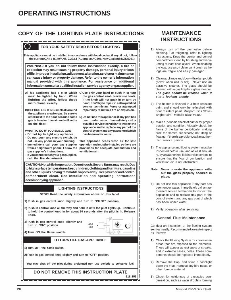
COPY OF THE LIGHTING PLATE INSTRUCTIONS
TO TURN OFF GAS APPLIANCE
FOR YOUR SAFETY READ BEFORE LIGHTING
This appliance must be installed in accordance with local codes, if any; if not, followthe current CAN1-B149/ANSI Z 223.1 (Australia: AG601, New Zealand: NZS 5261)
1) Turn OFF the flame switch.
2) Push in gas control knob slightly and turn to "OFF" position.
CAUTION: Hot while in operation. Do not touch. Severe Burns may result. Dueto high surface temperatures keep children, clothing and furniture, gasolineand other liquids having fammable vapors away. Keep burner and controlcompartment clean. See installation and operating instructionsaccompanying appliance.
LIGHTING INSTRUCTIONS
A)This appliance has a pilot whichmust be lighted by hand. Whenlighting the pilot, follow theseinstructions exactly.
B) BEFORE LIGHTING smell all aroundthe appliance area for gas. Be sure tosmell next to the floor because somegas is heavier than air and will settleon the floor.
WHAT TO DO IF YOU SMELL GAS- Do not try to light any appliance- Do not touch any electric switch, do
not use any phone in your building- Immediately call your gas supplier
from a neighbours phone. Follow thegas supplier’s instructions.
- If you cannot reach your gas supplier,call the fire department.
C)Use only your hand to push in or turnthe gas control knob. Never use tools.If the knob will not push in or turn byhand, don’t try to repair it, call a qualifiedservice technician. Force or attemptedrepair may result in a fire or explosion.
D) Do not use this appliance if any part hasbeen under water. Immediately call aqualified service technician to inspect theappliance and to replace any part of thecontrol system and any gas control whichhas been under water.
This appliance needs fresh air for safeoperation and must be installed so there areprovisions for adequate combustion andventilation air.
DO NOT REMOVE THIS INSTRUCTION PLATE
WARNING: If you do not follow these instructions exactly, a fire orexplosion may result causing property damage, personal injury or lossof life. Improper installation, adjustment, alteration, service or maintenancecan cause injury or property damage. Refer to the owner’s informationmanual provided with this appliance. For assistance or additionalinformation consult a qualified installer, service agency or gas supplier.
918-253
You may shut off the pilot during prolonged non use periods to conserve fuel.
STOP! Read the safety information above on this label.
1) Push in gas control knob slightly and turn to “PILOT” position.
2) Push in control knob all the way and hold in until the pilot lights up. Continueto hold the control knob in for about 20 seconds after the pilot is lit. Releaseknob.
3) Push in gas control knob slightly andturn to "ON" position.
4) Turn ON the flame switch.
Masport P36-3 Gas Inbuilt 29
MAINTENANCE
in the inner liner, and subsequently drippingout the joints, Continuous condensationcan cause corrosion of caps, pipe, andfittings. It may be caused by having exces-sive lateral runs, too many elbows, andexterior portions of the system being ex-posed to cold weather.
4) Inspect joints, to verify that no pipe sectionsor fittings have been disturbed, and conse-quently loosened. Also check mechanicalsupports such as Wall Straps, or plumbers'tape for rigidity.
GOLD-PLATED orBRASS LOUVRES
The 24 carat gold-plated or brass finish on thelouvres and trim requires little maintenance,and need only be cleaned with a damp cloth. DONOT use abrasive materials or chemical clean-ers, as they may harm the finish and void thewarranty. Clean any fingerprints off be-fore turning the unit on.
GOLD-PLATED orBRASS TRIM
The 24 carat gold plated or brass finish on thetrim requires little maintenance, and need onlybe cleaned with a damp cloth. DO NOT useabrasive materials or chemical cleaners, asthey may harm the finish and void the warranty.Clean any fingerprints off before turningthe unit on. If the top louvres start todiscolour, check the door gasket sealand replace if necessary.
LOG REPLACEMENT
The unit should never be used with broken logs.Turn off the gas valve and allow the unit to coolbefore opening door and carefully remove thelogs. (The pilot light generates enough heat toburn someone.) If for any reason a log shouldneed replacement, you must use the properreplacement log. The position of these logsmust be as shown in the diagrams under LogInstallation.
Note: Improper positioning of logs maycreate carbon build-up and willseverely alter the unit's perform-ance which is not covered underwarranty.
FIREBOX PAINT
The interior of the firebox is subject to extremelyhigh flame temperatures. While the paintedsurface is designed for high durability, thecombustion conditions can cause deteriorationof the paint finish. This is not unique to MasportGas Fires.
If the surface discolors or blisters simply scuffany loose paint from the firebox and lightlyrespray with Masport high temperature paint.
GLASS GASKET
If the glass gasket requires replacement use5/8" flat glass gasket for the Bay Front (Part #936-243) and a tadpole glass gasket for theFlush Front (Part # 936-155).
DOOR GLASS
Your Masport stove is supplied with high tem-perature, 5 mm Neoceram ceramic glass thatwill withstand the highest heat that your unit willproduce. If your glass requires cleaning, werecommend using a domestic glass cleaner. Donot use abrasive materials. Do not clean theglass when hot.
In the event that you break your glass by impact,purchase your replacement from an authorizedMasport dealer only, and follow our step-by-step instructions for replacement.
WARNING: Do not operate theappliance with the glass panelsremoved, cracked or broken.Replacement of the glass panelsshould be done by a licensed orqualified service person.
Caution: Wear gloves when remov-ing damaged or broken glass.
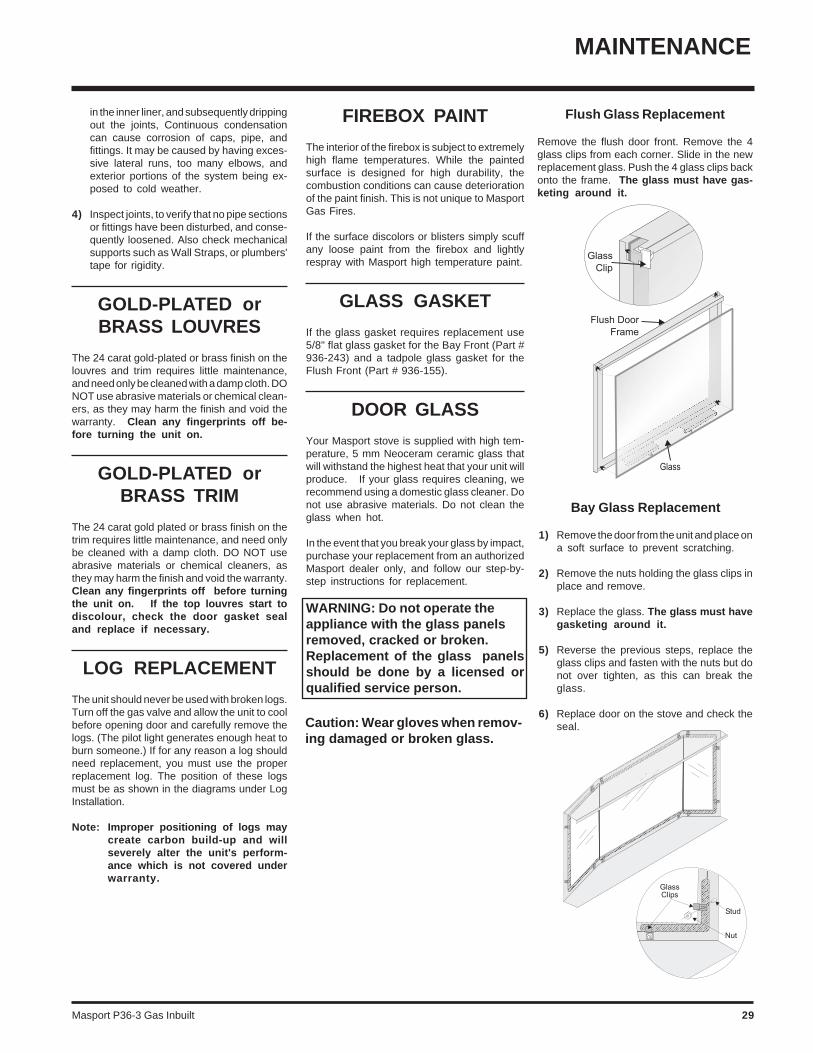
Flush Glass Replacement
Remove the flush door front. Remove the 4glass clips from each corner. Slide in the newreplacement glass. Push the 4 glass clips backonto the frame. The glass must have gas-keting around it.
Bay Glass Replacement
1) Remove the door from the unit and place ona soft surface to prevent scratching.
2) Remove the nuts holding the glass clips inplace and remove.
3) Replace the glass. The glass must havegasketing around it.
5) Reverse the previous steps, replace theglass clips and fasten with the nuts but donot over tighten, as this can break theglass.
6) Replace door on the stove and check theseal.
Masport P36-3 Gas Inbuilt30
10) Undo the pilot tube from the valve with a 7/16" spanner.
11) Undo the quick drop out thermocouple nuton the valve with a 9mm (metric) spanner.
12) Remove the Piezo igniter wire and pushbutton assembly.
13) Undo the "gas out" flare nut with a 13/16"spanner.
14) Undo the "gas out" flare fitting with an 11/16" spanner.
15) Remove the 4 Phillips head screws from thesides of the valve bracket and removevalve.
Hint: If you are using black pipe, en-sure that there is a union by thevalve, otherwise removal will bealmost impossible.
INSTALLING VALVE
1) Attach the valve to the valve bracket with the4 (m5x8 metric) screws provided.
2) Reconnect the "gas out" flare fitting with an11/16" spanner.
3) Reconnect the "gas out" flare nut with a13/16" spanner.
4) Install piezo ignitor push button assembly andreconnect wire.
5) Reconnect the quick drop out thermocouplenut with a 9mm spanner.
6) Reconnect the pilot tube nut with a 7/16"spanner.
7) Scrape off the old gasket from the floor of thefirebox and from the valve tray assembly.
8) Install a new gasket and reinstall the valvetray assembly.
Note: Failure to install a new gasket mayseverely affect the appliance per-formance.
9) Reinstall the 10 hold down screws.
10) Hook up the 2 TP and 2 TH wires to theappropriate connections on the valve.
11) Reinstall the front log stand.
12) Install Burner/grate assembly
13) Hook up the gas line and check for gas leakswith a soap and water solution or a gas leakdetector. (Do not use open flame for leaktesting.)
14) Fire up the unit temporarily
15) Check the manifold pressure.
16) Reinstall the logs and brick panels as needed.
17) Close the door and replace the louvres.
18) Fire up the unit again and check for properflame appearance and glow on logs.
REMOVING VALVE
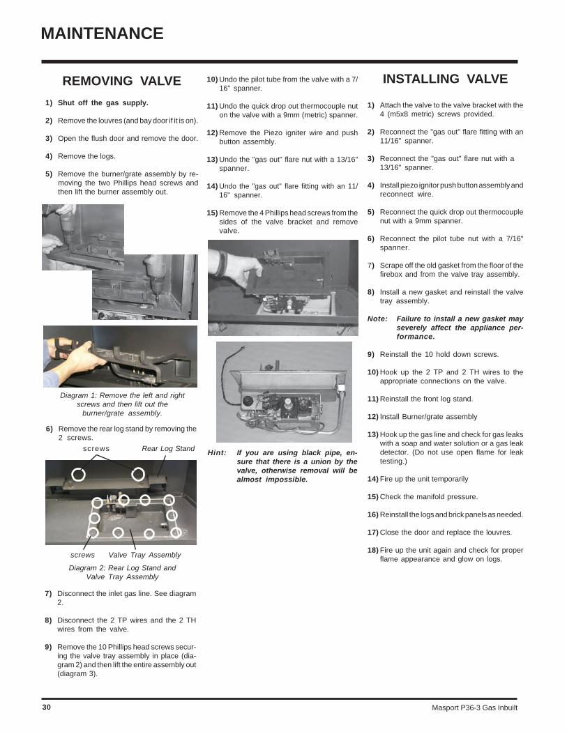
1) Shut off the gas supply.
2) Remove the louvres (and bay door if it is on).
3) Open the flush door and remove the door.
4) Remove the logs.
5) Remove the burner/grate assembly by re-moving the two Phillips head screws andthen lift the burner assembly out.
Diagram 1: Remove the left and rightscrews and then lift out the
burner/grate assembly.
6) Remove the rear log stand by removing the2 screws.
Diagram 2: Rear Log Stand andValve Tray Assembly
screws Valve Tray Assembly
Rear Log Standscrews
7) Disconnect the inlet gas line. See diagram2.
8) Disconnect the 2 TP wires and the 2 THwires from the valve.
9) Remove the 10 Phillips head screws secur-ing the valve tray assembly in place (dia-gram 2) and then lift the entire assembly out(diagram 3).
MAINTENANCE
Masport P36-3 Gas Inbuilt 31
PARTS LIST
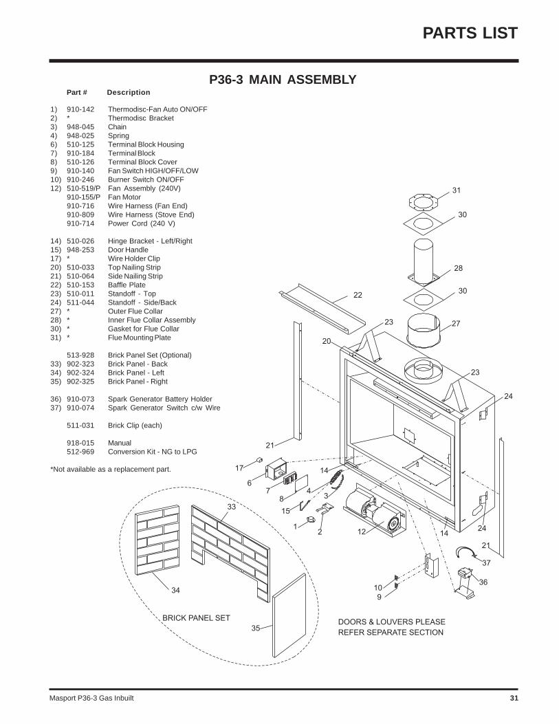
P36-3 MAIN ASSEMBLY Part # Description
1) 910-142 Thermodisc-Fan Auto ON/OFF2) * Thermodisc Bracket3) 948-045 Chain4) 948-025 Spring6) 510-125 Terminal Block Housing7) 910-184 Terminal Block8) 510-126 Terminal Block Cover9) 910-140 Fan Switch HIGH/OFF/LOW10) 910-246 Burner Switch ON/OFF12) 510-519/P Fan Assembly (240V)
910-155/P Fan Motor910-716 Wire Harness (Fan End)910-809 Wire Harness (Stove End)910-714 Power Cord (240 V)
14) 510-026 Hinge Bracket - Left/Right15) 948-253 Door Handle17) * Wire Holder Clip20) 510-033 Top Nailing Strip21) 510-064 Side Nailing Strip22) 510-153 Baffle Plate23) 510-011 Standoff - Top24) 511-044 Standoff - Side/Back27) * Outer Flue Collar28) * Inner Flue Collar Assembly30) * Gasket for Flue Collar31) * Flue Mounting Plate
513-928 Brick Panel Set (Optional)33) 902-323 Brick Panel - Back34) 902-324 Brick Panel - Left35) 902-325 Brick Panel - Right
36) 910-073 Spark Generator Battery Holder37) 910-074 Spark Generator Switch c/w Wire
511-031 Brick Clip (each)
918-015 Manual512-969 Conversion Kit - NG to LPG
*Not available as a replacement part.
Masport P36-3 Gas Inbuilt32
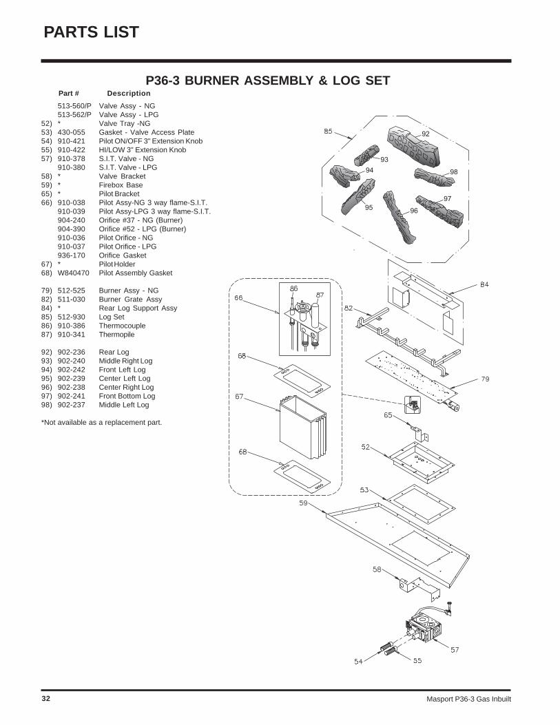
P36-3 BURNER ASSEMBLY & LOG SET Part # Description
PARTS LIST
513-560/P Valve Assy - NG513-562/P Valve Assy - LPG
52) * Valve Tray -NG53) 430-055 Gasket - Valve Access Plate54) 910-421 Pilot ON/OFF 3" Extension Knob55) 910-422 HI/LOW 3" Extension Knob57) 910-378 S.I.T. Valve - NG
910-380 S.I.T. Valve - LPG58) * Valve Bracket59) * Firebox Base65) * Pilot Bracket66) 910-038 Pilot Assy-NG 3 way flame-S.I.T.
910-039 Pilot Assy-LPG 3 way flame-S.I.T.904-240 Orifice #37 - NG (Burner)904-390 Orifice #52 - LPG (Burner)910-036 Pilot Orifice - NG910-037 Pilot Orifice - LPG936-170 Orifice Gasket
67) * Pilot Holder68) W840470 Pilot Assembly Gasket
79) 512-525 Burner Assy - NG82) 511-030 Burner Grate Assy84) * Rear Log Support Assy85) 512-930 Log Set86) 910-386 Thermocouple87) 910-341 Thermopile
92) 902-236 Rear Log93) 902-240 Middle Right Log94) 902-242 Front Left Log95) 902-239 Center Left Log96) 902-238 Center Right Log97) 902-241 Front Bottom Log98) 902-237 Middle Left Log
*Not available as a replacement part.
Masport P36-3 Gas Inbuilt 33
PARTS LIST
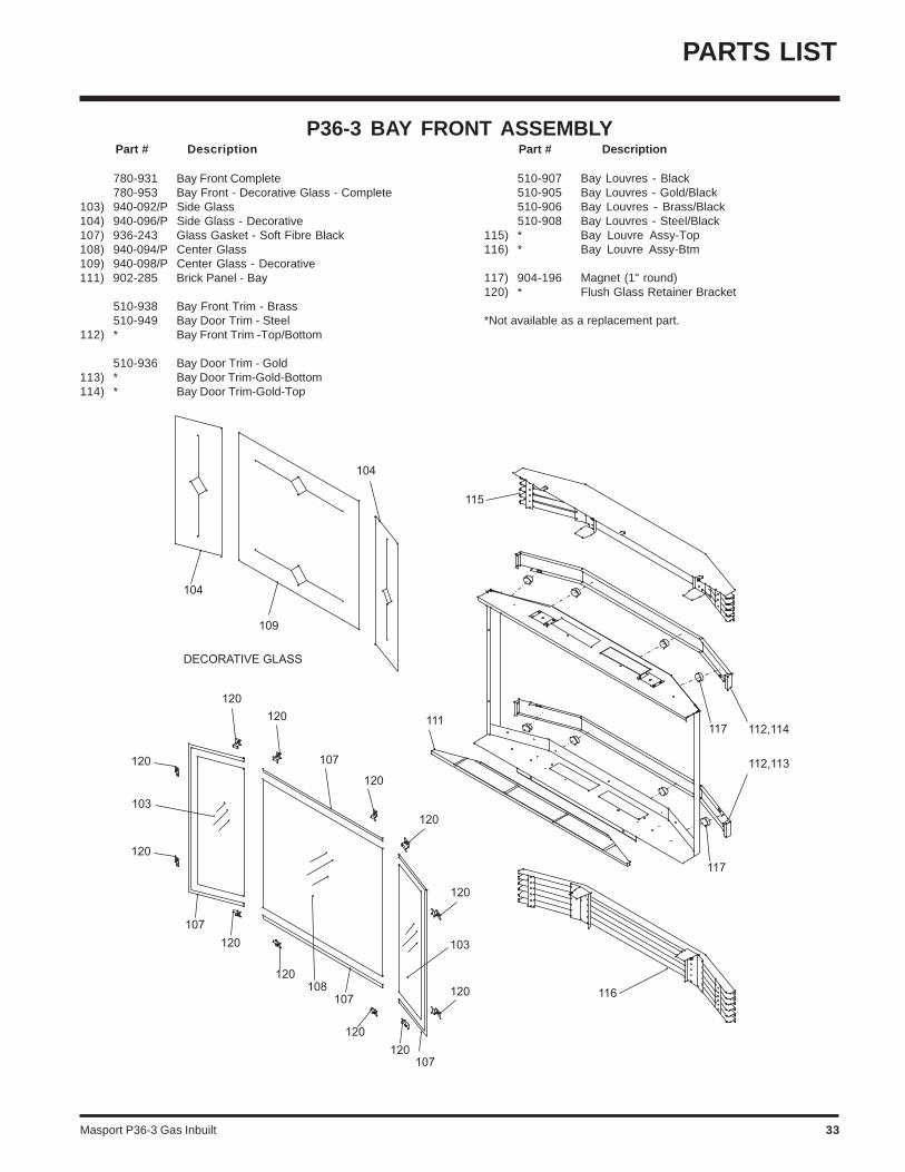
P36-3 BAY FRONT ASSEMBLY Part # Description Part # Description
780-931 Bay Front Complete780-953 Bay Front - Decorative Glass - Complete
103) 940-092/P Side Glass104) 940-096/P Side Glass - Decorative107) 936-243 Glass Gasket - Soft Fibre Black108) 940-094/P Center Glass109) 940-098/P Center Glass - Decorative111) 902-285 Brick Panel - Bay
510-938 Bay Front Trim - Brass510-949 Bay Door Trim - Steel
112) * Bay Front Trim -Top/Bottom
510-936 Bay Door Trim - Gold113) * Bay Door Trim-Gold-Bottom114) * Bay Door Trim-Gold-Top
510-907 Bay Louvres - Black510-905 Bay Louvres - Gold/Black510-906 Bay Louvres - Brass/Black510-908 Bay Louvres - Steel/Black
115) * Bay Louvre Assy-Top116) * Bay Louvre Assy-Btm
117) 904-196 Magnet (1" round)120) * Flush Glass Retainer Bracket
*Not available as a replacement part.
Masport P36-3 Gas Inbuilt34
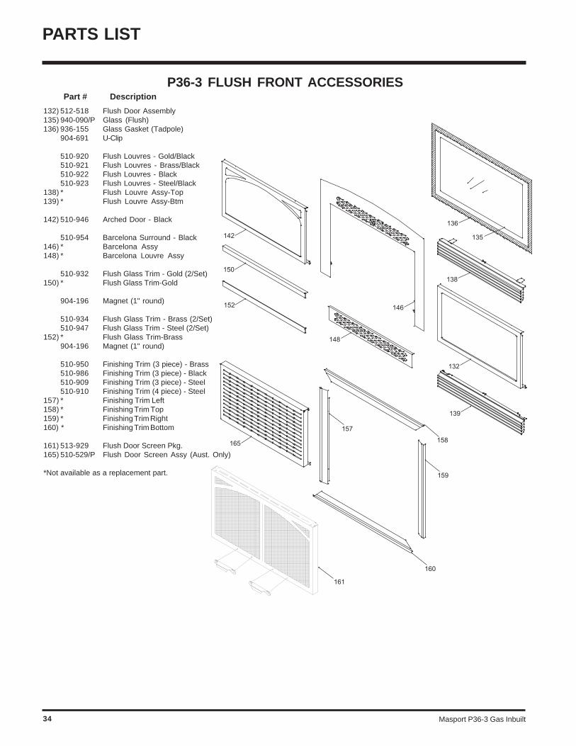
P36-3 FLUSH FRONT ACCESSORIES Part # Description
PARTS LIST
132) 512-518 Flush Door Assembly135) 940-090/P Glass (Flush)136) 936-155 Glass Gasket (Tadpole)
904-691 U-Clip
510-920 Flush Louvres - Gold/Black510-921 Flush Louvres - Brass/Black510-922 Flush Louvres - Black510-923 Flush Louvres - Steel/Black
138) * Flush Louvre Assy-Top139) * Flush Louvre Assy-Btm
142) 510-946 Arched Door - Black
510-954 Barcelona Surround - Black146) * Barcelona Assy148) * Barcelona Louvre Assy
510-932 Flush Glass Trim - Gold (2/Set)150) * Flush Glass Trim-Gold
904-196 Magnet (1" round)
510-934 Flush Glass Trim - Brass (2/Set)510-947 Flush Glass Trim - Steel (2/Set)
152) * Flush Glass Trim-Brass904-196 Magnet (1" round)
510-950 Finishing Trim (3 piece) - Brass510-986 Finishing Trim (3 piece) - Black510-909 Finishing Trim (3 piece) - Steel510-910 Finishing Trim (4 piece) - Steel
157) * Finishing Trim Left158) * Finishing Trim Top159) * Finishing Trim Right160) * Finishing Trim Bottom
161) 513-929 Flush Door Screen Pkg.165) 510-529/P Flush Door Screen Assy (Aust. Only)
*Not available as a replacement part.
Masport P36-3 Gas Inbuilt 35
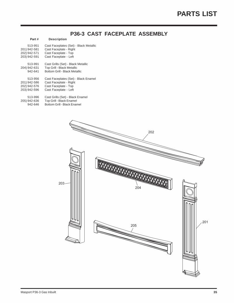
P36-3 CAST FACEPLATE ASSEMBLY Part # Description
PARTS LIST
513-951 Cast Faceplates (Set) - Black Metallic201) 942-581 Cast Faceplate - Right202) 942-571 Cast Faceplate - Top203) 942-591 Cast Faceplate - Left
513-991 Cast Grills (Set) - Black Metallic204) 942-631 Top Grill - Black Metallic
942-641 Bottom Grill - Black Metallic
513-956 Cast Faceplates (Set) - Black Enamel201) 942-586 Cast Faceplate - Right202) 942-576 Cast Faceplate - Top203) 942-596 Cast Faceplate - Left
513-996 Cast Grills (Set) - Black Enamel205) 942-636 Top Grill - Black Enamel
942-646 Bottom Grill - Black Enamel

Masport P36-3 Gas Inbuilt36
_____________________________________________________________________________________
____________________________________________________________
__________________________________________________________
____________________________________________________________
_______________________________________________________
_____________________________________________________
__________________________________________________________
_________________________________________________________
_________________________________________________________
______________________________________________________
______________________________________________________
_______________________________________________________________
___________________________________________________________
__________________________________________________________
____________________________________________________________
____________________________________________________________
____________________________________________________________
_____________________________________________________________
__________________________________________________________
__________________________________________________________
_____________________________________________________
________________________________________________________
_________________________________________________________
_________________________________________________________
NOTES

Masport P36-3 Gas Inbuilt 37
_____________________________________________________________________________________
____________________________________________________________
__________________________________________________________
____________________________________________________________
_______________________________________________________
_____________________________________________________
__________________________________________________________
_________________________________________________________
_________________________________________________________
______________________________________________________
______________________________________________________
_______________________________________________________________
___________________________________________________________
__________________________________________________________
____________________________________________________________
____________________________________________________________
____________________________________________________________
_____________________________________________________________
__________________________________________________________
__________________________________________________________
_____________________________________________________
________________________________________________________
_________________________________________________________
_________________________________________________________
NOTES

Masport P36-3 Gas Inbuilt38
_____________________________________________________________________________________
____________________________________________________________
__________________________________________________________
____________________________________________________________
_______________________________________________________
_____________________________________________________
__________________________________________________________
_________________________________________________________
_________________________________________________________
______________________________________________________
______________________________________________________
_______________________________________________________________
___________________________________________________________
__________________________________________________________
____________________________________________________________
____________________________________________________________
____________________________________________________________
_____________________________________________________________
__________________________________________________________
__________________________________________________________
_____________________________________________________
________________________________________________________
_________________________________________________________
_________________________________________________________
NOTES
Masport P36-3 Gas Inbuilt 39
WARRANTY
THE MASPORT EXPRESS WARRANTYAll new Masport Gas appliances are warranted, subject to the followingconditions, to be free from defects in material or workmanship undernormal use. The Express Warranty on all parts, including fireboxcomponents but excluding fans, flues and flue accessories is two yearsfrom date of original purchase as well as labour costs involved in therepair or replacement. The Express Warranty on fans, flues andaccessories is for a period of twelve months from date of originalpurchase and includes labour costs involved in the repair or replace-ment.
This Express Warranty applies only with respect to defects in materialand workmanship under normal and proper use of the NEW UNIT in itsunmodified condition. Masport's obligation under this Express Warrantyis limited to the repair or replacement, at its option, by an approvedMasport Gas Service Agent (Retailer) of any part found to be defectivein material or workmanship.
Labour costs involved in the repair or replacement are also coveredunder this Express Warranty as per the time condition outlined.
If an approved Masport Gas Service Agent is requested to attend on aservice call that is not covered under this Express Warranty, a call outcharge may be applicable, regardless of whether a repair is carried outor not.
Masport can accept no obligation whatsoever for any incidental,consequential or special damages or expenses resulting from anyproduct defect. This Express Warranty applies from the date of originalpurchase, applies to the original purchaser, and is not transferable. Thedecision to repair or replace defective components will be made byMasport or its agent and actioned by an approved Masport ServiceAgent.
This Express Warranty Does Not Cover:1. Defects, malfunctions or failures caused by incorrect installation,
normal wear and tear, misuse, neglect, accidental damage or failureto follow the fuel selection, product operating and maintenanceinstructions, or resulting from installations, repairs or modificationsto the equipment carried out by unauthorised persons.
2. Defects, malfunctions or failures caused by an act or omission ofother persons after the product has left Masport's control.
3. The costs of collection and delivery of the equipment.4. The cost of labour or materials as a consequence of faulty
installation of gas supply line, flue, burner or log settings, or non-compliance with local codes.
The Express Warranty is not intended to exclude any rights thepurchaser may have under the laws of the place, state, orcountry of purchase. Nothing in this Express Warranty limits orrestricts any other statutory right or remedy available to thepurchaser.
How You Obtain Warranty Service:Provide proof of the date of purchase. Should the need for a warrantyclaim arise reasonable proof of the purchase date is required thereforeyou should retain your sales receipt. Where flueless appliances are notpermanently installed, they should be returned to a Service Agent forevaluation.
Make the faulty part(s) available for inspection by Masport and/or itsagents so that the validity of the claim can be established by them.
Australia Distributor:
Masport Pty LimitedP.O. Box 533Mordialloc 3195Victoria
For your own records, please complete the following:
Model: ________________________________________ Serial Number: ____________________________
New Zealand:
Masport LimitedP.O. Box 14-349PanmureAuckland 6
Retailer: ________________________________________________________________________________
______________________________________________________________________________________
Purchase Date: _______________________________

Printed in Canada© Copyright 2004, FPI Fireplace Products International Ltd. All rights reserved.