p2m eom - wilden pumps · wil-10180-e-02 1 wilden pump & engineering, llc temperature limits:...
TRANSCRIPT
EOM
S i m p l i f y y o u r p r o c e s s
E n g i n e e r i n g O p e r a t i o n &M a i n t e n a n c eOriginal™ Series METAL Pumps
P2M
WIL-10180-E-02Replaces EOM-P2M 04/05
TABLE OF CONTENTSPAGE #
SECTION 1 — CAUTIONS ............................................................................................ 1
SECTION 2 — PUMP DESIGNATION SYSTEM ......................................... 2
SECTION 3 — HOW IT WORKS (PUMP & AIR SYSTEMS) ............ 3
SECTION 4 — DIMENSIONAL DRAWINGSA. P2 METAL .................................................................................................................... 4
B. P2 METAL SANIFLOFDA ...................................................................................................... 4
C. P2 METAL Bolted ............................................................................................................... 5
SECTION 5 — PERFORMANCE CURVESA. P2 METAL Rubber-Fitted ................................................................................................... 6
B. P2 METAL TPE-Fitted ........................................................................................................ 6
C. P2 METAL PTFE-Fitted ...................................................................................................... 7
SECTION 6 — SUCTION LIFT CURVES ........................................................... 7
SECTION 7 — INSTALLATION AND OPERATIONA. Installation .......................................................................................................................... 8
B. Operation & Maintenance .................................................................................................. 9
C. Troubleshooting .................................................................................................................. 10
SECTION 8 — DIRECTIONS FOR DISASSEMBLY/REASSEMBLYA. P2 METAL Wetted Path — Tools Required, Torque Specs, Cautions ............................... 11
B. Pro-Flo® Air Valve/Center Block – Disassembly, Cleaning, Inspection ............................. 13
C. Reassembly Hints & Tips ................................................................................................... 15
SECTION 9 — EXPLODED VIEW/PARTS LISTINGA. P2 METAL Rubber/TPE-Fitted ........................................................................................... 16
B. P2 METAL PTFE-Fitted ...................................................................................................... 18
SECTION 10 — ELASTOMER OPTIONS ......................................................... 20
Cla
ss
I &II Ozone
Depleting Substanc
esNON
USEU.S. Clean Air Act
Amendments of 1990
1 WILDEN PUMP & ENGINEERING, LLCWIL-10180-E-02
TEMPERATURE LIMITS: Polypropylene 0°C to 79.4°C 32°F to 175°F Acetal –28.9°C to 65.6°C –20°F to 150°F Neoprene –17.8°C to 93.3°C 0°F to 200°F Buna-N –12.2°C to 82.2°C 10°F to 180°F EPDM –51.1°C to 137.8°C –60°F to 280°F Viton® –40°C to 176.7°C –40°F to 350°F Wil-Flex™ –40°C to 107.2°C –40°F to 225°F Polyurethane –12.2°C to 65.6°C 10°F to 150°F Saniflex™ –28.9°C to 104.4°C –20°F to 220°F PTFE 4.4°C to 148.9°C 40°F to 300°F
CAUTION: When choosing pump materials, be sure to check the temperature limits for all wetted compo-nents. Example: Viton® has a maximum limit of 176.7°C (350°F) but Acetal has a maximum limit of only 65.6°C (150°F).
CAUTION: Maximum temperature limits are based upon mechanical stress only. Certain chemicals will significantly reduce maximum safe operating tempera-tures. Consult engineering guide for chemical compat-ibility and temperature limits.
CAUTION: Always wear safety glasses when operat-ing pump. If diaphragm rupture occurs, material being pumped may be forced out air exhaust.
WARNING: Prevention of static sparking — If static sparking occurs, fire or explosion could result. Pump, valves, and containers must be properly grounded when handling flammable fluids and whenever discharge of static electricity is a hazard.
CAUTION: Do not exceed 8.6 bar (125 psig) air supply pressure.
CAUTION: Before any maintenance or repair is attempted, the compressed air line to the pump should be disconnected and all air pressure allowed to bleed from pump. Disconnect all intake, discharge and air lines. Drain the pump by turning it upside down and allowing any fluid to flow into a suitable container.
CAUTION: Blow out air line for 10 to 20 seconds before attaching to pump to make sure all pipe line debris is clear. Use an in-line air filter. A 5 µ (micron) air filter is recommended.
NOTE: Tighten all hardware prior to installation. Fittings may loosen during transportation.
NOTE: When installing PTFE diaphragms, it is impor-tant to tighten outer pistons simultaneously (turning in opposite directions) to ensure tight fit.
NOTE: Before starting disassembly, mark a line from each liquid chamber to its corresponding air chamber. This line will assist in proper alignment during reas-sembly.
CAUTION: Verify the chemical compatibility of the process and cleaning fluid to the pump’s component materials in the Chemical Resistance Guide (see E4).
CAUTION: Do not over-tighten the air inlet reducer bushing. Too much torque on the reducer may damage either the reducer bushing or center section. Do not exceed 10.9 N•m (8 ft-lbs).
CAUTION: Do not exceed the maximum torque specification of 13.0 N•m (115 in-lbs) on the liquid chamber to air chamber fasteners on the P2 Bolted configuration.
SECTION 1
P2 METALCAUTIONS – READ FIRST!
2WILDEN PUMP & ENGINEERING, LLC WIL-10180-E-02
SECTION 2
WILDEN PUMP DESIGNATION SYSTEM
NOTE: MOST ELASTOMERIC MATERIALS USE COLORED DOTS FOR IDENTIFICATION.
Viton is a registered trademarks of DuPont Dow Elastomers.
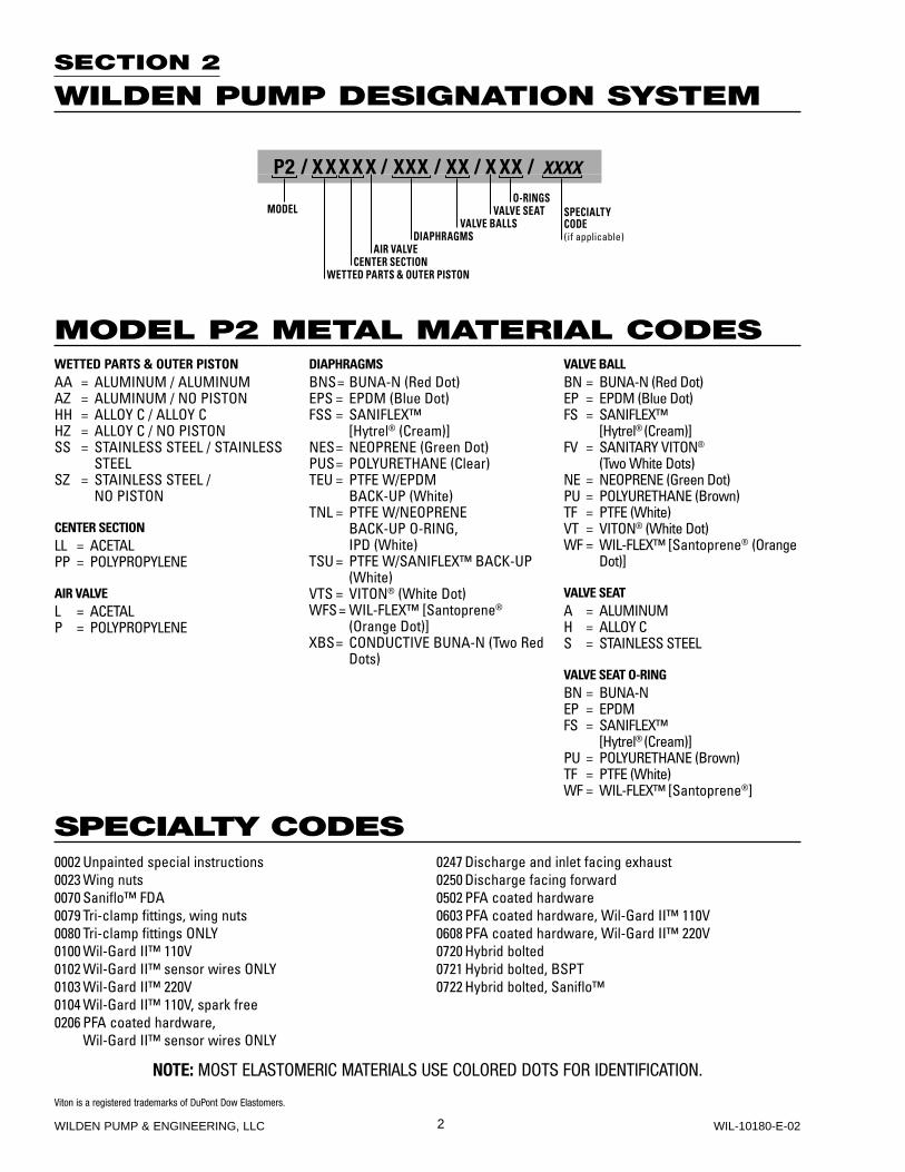
P2 / XXXXX / XXX / XX / X XX / XXXX
O-RINGSMODEL VALVE SEAT
VALVE BALLSDIAPHRAGMS
AIR VALVECENTER SECTION
WETTED PARTS & OUTER PISTON
SPECIALTYCODE(if applicable)
MODEL P2 METAL MATERIAL CODES
SPECIALTY CODES
WETTED PARTS & OUTER PISTONAA = ALUMINUM / ALUMINUMAZ = ALUMINUM / NO PISTONHH = ALLOY C / ALLOY CHZ = ALLOY C / NO PISTONSS = STAINLESS STEEL / STAINLESS
STEELSZ = STAINLESS STEEL /
NO PISTON
CENTER SECTIONLL = ACETALPP = POLYPROPYLENE
AIR VALVEL = ACETALP = POLYPROPYLENE
DIAPHRAGMSBNS = BUNA-N (Red Dot)EPS = EPDM (Blue Dot)FSS = SANIFLEX™
[Hytrel® (Cream)]NES = NEOPRENE (Green Dot)PUS = POLYURETHANE (Clear)TEU = PTFE W/EPDM BACK-UP (White)TNL = PTFE W/NEOPRENE
BACK-UP O-RING, IPD (White)
TSU = PTFE W/SANIFLEX™ BACK-UP (White)
VTS = VITON® (White Dot)WFS = WIL-FLEX™ [Santoprene®
(Orange Dot)]XBS = CONDUCTIVE BUNA-N (Two Red
Dots)
VALVE BALLBN = BUNA-N (Red Dot)EP = EPDM (Blue Dot)FS = SANIFLEX™
[Hytrel® (Cream)]FV = SANITARY VITON®
(Two White Dots)NE = NEOPRENE (Green Dot)PU = POLYURETHANE (Brown)TF = PTFE (White)VT = VITON® (White Dot)WF = WIL-FLEX™ [Santoprene® (Orange
Dot)]
VALVE SEATA = ALUMINUMH = ALLOY CS = STAINLESS STEEL
VALVE SEAT O-RINGBN = BUNA-N EP = EPDMFS = SANIFLEX™
[Hytrel® (Cream)]PU = POLYURETHANE (Brown)TF = PTFE (White)WF = WIL-FLEX™ [Santoprene®]
0002 Unpainted special instructions0023 Wing nuts0070 Saniflo™ FDA0079 Tri-clamp fittings, wing nuts0080 Tri-clamp fittings ONLY0100 Wil-Gard II™ 110V0102 Wil-Gard II™ sensor wires ONLY0103 Wil-Gard II™ 220V0104 Wil-Gard II™ 110V, spark free0206 PFA coated hardware,
Wil-Gard II™ sensor wires ONLY
0247 Discharge and inlet facing exhaust0250 Discharge facing forward0502 PFA coated hardware0603 PFA coated hardware, Wil-Gard II™ 110V0608 PFA coated hardware, Wil-Gard II™ 220V0720 Hybrid bolted0721 Hybrid bolted, BSPT0722 Hybrid bolted, Saniflo™
3 WILDEN PUMP & ENGINEERING, LLCWIL-10180-E-02
SECTION 3
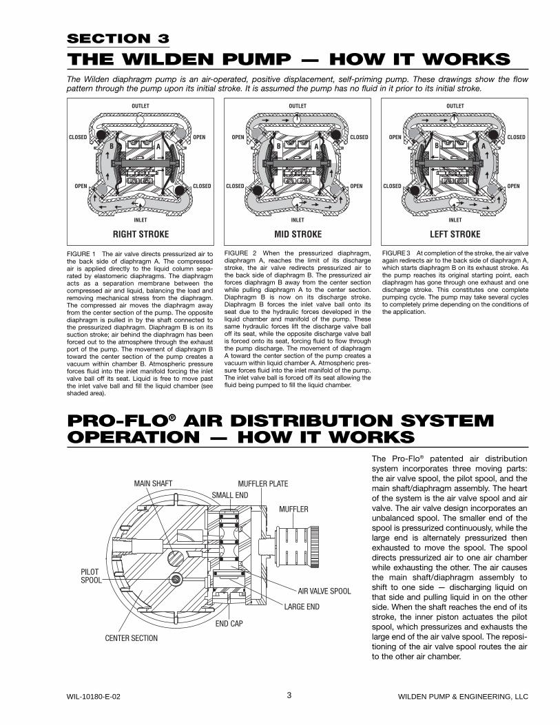
THE WILDEN PUMP — HOW IT WORKSThe Wilden diaphragm pump is an air-operated, positive displacement, self-priming pump. These drawings show the flow pattern through the pump upon its initial stroke. It is assumed the pump has no fluid in it prior to its initial stroke.
FIGURE 1 The air valve directs pressurized air to the back side of diaphragm A. The compressed air is applied directly to the liquid column sepa-rated by elastomeric diaphragms. The diaphragm acts as a separation membrane between the compressed air and liquid, balancing the load and removing mechanical stress from the diaphragm. The compressed air moves the diaphragm away from the center section of the pump. The opposite diaphragm is pulled in by the shaft connected to the pressurized diaphragm. Diaphragm B is on its suction stroke; air behind the diaphragm has been forced out to the atmosphere through the exhaust port of the pump. The movement of diaphragm B toward the center section of the pump creates a vacuum within chamber B. Atmospheric pressure forces fluid into the inlet manifold forcing the inlet valve ball off its seat. Liquid is free to move past the inlet valve ball and fill the liquid chamber (see shaded area).
FIGURE 2 When the pressurized diaphragm, diaphragm A, reaches the limit of its discharge stroke, the air valve redirects pressurized air to the back side of diaphragm B. The pressurized air forces diaphragm B away from the center section while pulling diaphragm A to the center section. Diaphragm B is now on its discharge stroke. Diaphragm B forces the inlet valve ball onto its seat due to the hydraulic forces developed in the liquid chamber and manifold of the pump. These same hydraulic forces lift the discharge valve ball off its seat, while the opposite discharge valve ball is forced onto its seat, forcing fluid to flow through the pump discharge. The movement of diaphragm A toward the center section of the pump creates a vacuum within liquid chamber A. Atmospheric pres-sure forces fluid into the inlet manifold of the pump. The inlet valve ball is forced off its seat allowing the fluid being pumped to fill the liquid chamber.
FIGURE 3 At completion of the stroke, the air valve again redirects air to the back side of diaphragm A, which starts diaphragm B on its exhaust stroke. As the pump reaches its original starting point, each diaphragm has gone through one exhaust and one discharge stroke. This constitutes one complete pumping cycle. The pump may take several cycles to completely prime depending on the conditions of the application.
PRO-FLO® AIR DISTRIBUTION SYSTEMOPERATION — HOW IT WORKS
The Pro-Flo® patented air distribution system incorporates three moving parts: the air valve spool, the pilot spool, and the main shaft/diaphragm assembly. The heart of the system is the air valve spool and air valve. The air valve design incorporates an unbalanced spool. The smaller end of the spool is pressurized continuously, while the large end is alternately pressurized then exhausted to move the spool. The spool directs pressurized air to one air chamber while exhausting the other. The air causes the main shaft/diaphragm assembly to shift to one side — discharging liquid on that side and pulling liquid in on the other side. When the shaft reaches the end of its stroke, the inner piston actuates the pilot spool, which pressurizes and exhausts the large end of the air valve spool. The reposi-tioning of the air valve spool routes the air to the other air chamber.
4WILDEN PUMP & ENGINEERING, LLC WIL-10180-E-02
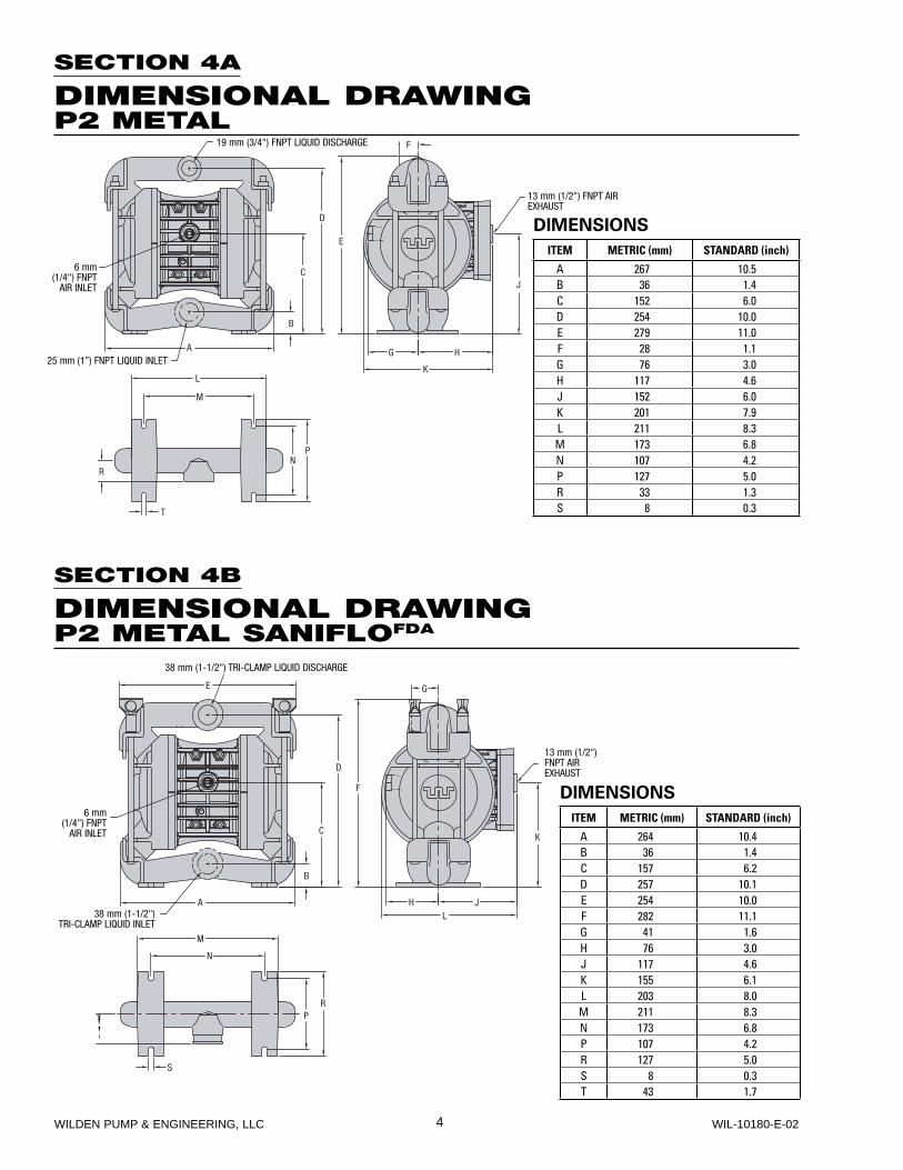
SECTION 4B
DIMENSIONAL DRAWINGP2 METAL SANIFLOFDA
38 mm (1-1/2") TRI-CLAMP LIQUID DISCHARGE
38 mm (1-1/2") TRI-CLAMP LIQUID INLET
6 mm (1/4") FNPT
AIR INLET
13 mm (1/2") FNPT AIR EXHAUST
DIMENSIONS
ITEM METRIC (mm) STANDARD (inch)
A 264 10.4B 36 1.4C 157 6.2D 257 10.1E 254 10.0F 282 11.1G 41 1.6H 76 3.0J 117 4.6K 155 6.1L 203 8.0M 211 8.3N 173 6.8P 107 4.2R 127 5.0S 8 0.3T 43 1.7
SECTION 4A
DIMENSIONAL DRAWINGP2 METAL
19 mm (3/4") FNPT LIQUID DISCHARGE
13 mm (1/2") FNPT AIR EXHAUST
25 mm (1”) FNPT LIQUID INLET
6 mm (1/4") FNPT
AIR INLET
DIMENSIONS
ITEM METRIC (mm) STANDARD (inch)
A 267 10.5B 36 1.4C 152 6.0D 254 10.0E 279 11.0F 28 1.1G 76 3.0H 117 4.6J 152 6.0K 201 7.9L 211 8.3M 173 6.8N 107 4.2P 127 5.0R 33 1.3S 8 0.3
5 WILDEN PUMP & ENGINEERING, LLCWIL-10180-E-02
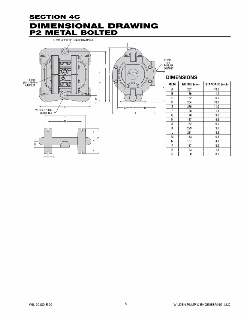
SECTION 4C
DIMENSIONAL DRAWINGP2 METAL BOLTED
19 mm (3/4") FNPT LIQUID DISCHARGE
25 mm (1") FNPT LIQUID INLET
13 mm (1/2”)FNPT AIR EXHAUST
6 mm (1/4") FNPT
AIR INLET
DIMENSIONS
ITEM METRIC (mm) STANDARD (inch)
A 267 10.5B 36 1.4C 152 6.0D 254 10.0E 279 11.0F 28 1.1G 76 3.0H 117 4.6J 152 6.0K 229 9.0L 211 8.3M 173 6.8N 107 4.2P 127 5.0R 33 1.3S 8 0.3
6WILDEN PUMP & ENGINEERING, LLC WIL-10180-E-02
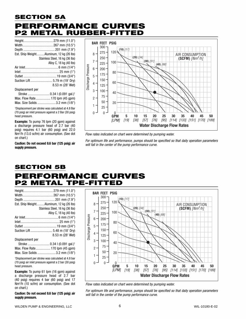
SECTION 5A
PERFORMANCE CURVESP2 METAL RUBBER-FITTEDHeight .................................. 279 mm (11.0")Width ................................... 267 mm (10.5")Depth .................................... 201 mm (7.9")Est. Ship Weight .........Aluminum, 12 kg (26 lbs)
Stainless Steel, 16 kg (36 lbs)Alloy C, 18 kg (40 lbs)
Air Inlet ......................................6 mm (1/4")Inlet ............................................ 25 mm (1")Outlet ......................................19 mm (3/4")Suction Lift ......................... 5.79 m (19' Dry)
8.53 m (28' Wet)Displacement per Stroke ......................... 0.34 l (0.091 gal.)1
Max. Flow Rate ................. 170 lpm (45 gpm)Max. Size Solids .....................3.2 mm (1/8")1Displacement per stroke was calculated at 4.8 Bar (70 psig) air inlet pressure against a 2 Bar (30 psig) head pressure.
Example: To pump 76 lpm (20 gpm) against a discharge pressure head of 2.7 bar (40 psig) requires 4.1 bar (60 psig) and 22.0 Nm3/h (13.0 scfm) air consumption. (See dot on chart.)
Caution: Do not exceed 8.6 bar (125 psig) air supply pressure.
Flow rates indicated on chart were determined by pumping water.
For optimum life and performance, pumps should be specified so that daily operation parameters will fall in the center of the pump performance curve.
[LPM]
SECTION 5B
PERFORMANCE CURVESP2 METAL TPE-FITTEDHeight .................................. 279 mm (11.0")Width ................................... 267 mm (10.5")Depth .................................... 201 mm (7.9")Est. Ship Weight .........Aluminum, 12 kg (26 lbs)
Stainless Steel, 16 kg (36 lbs)Alloy C, 18 kg (40 lbs)
Air Inlet ......................................6 mm (1/4")Inlet ............................................ 25 mm (1")Outlet ......................................19 mm (3/4")Suction Lift ......................... 5.48 m (18' Dry)
8.53 m (28' Wet)Displacement per Stroke ......................... 0.34 l (0.091 gal.)1
Max. Flow Rate ................. 170 lpm (45 gpm)Max. Size Solids .....................3.2 mm (1/8")1Displacement per stroke was calculated at 4.8 bar (70 psig) air inlet pressure against a 2 bar (30 psig) head pressure.
Example: To pump 61 lpm (16 gpm) against a discharge pressure head of 2.7 bar (40 psig) requires 4 bar (60 psig) and 17 Nm3/h (10 scfm) air consumption. (See dot on chart.)
Caution: Do not exceed 8.6 bar (125 psig) air supply pressure.
Flow rates indicated on chart were determined by pumping water.
For optimum life and performance, pumps should be specified so that daily operation parameters will fall in the center of the pump performance curve.
[LPM]
7 WILDEN PUMP & ENGINEERING, LLCWIL-10180-E-02
SECTION 6
SUCTION LIFT CURVES
SECTION 5C
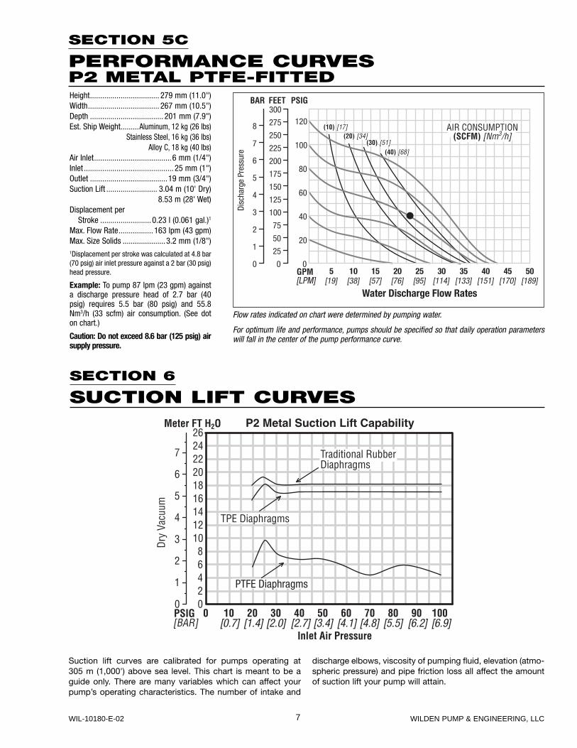
PERFORMANCE CURVESP2 METAL PTFE-FITTEDHeight .................................. 279 mm (11.0")Width ................................... 267 mm (10.5")Depth .................................... 201 mm (7.9")Est. Ship Weight .........Aluminum, 12 kg (26 lbs)
Stainless Steel, 16 kg (36 lbs)Alloy C, 18 kg (40 lbs)
Air Inlet ......................................6 mm (1/4")Inlet ............................................ 25 mm (1")Outlet ......................................19 mm (3/4")Suction Lift ......................... 3.04 m (10' Dry)
8.53 m (28' Wet)Displacement per Stroke ......................... 0.23 l (0.061 gal.)1
Max. Flow Rate ................. 163 lpm (43 gpm)Max. Size Solids .....................3.2 mm (1/8")1Displacement per stroke was calculated at 4.8 bar (70 psig) air inlet pressure against a 2 bar (30 psig) head pressure.
Example: To pump 87 lpm (23 gpm) against a discharge pressure head of 2.7 bar (40 psig) requires 5.5 bar (80 psig) and 55.8 Nm3/h (33 scfm) air consumption. (See dot on chart.)
Caution: Do not exceed 8.6 bar (125 psig) air supply pressure.
Flow rates indicated on chart were determined by pumping water.
For optimum life and performance, pumps should be specified so that daily operation parameters will fall in the center of the pump performance curve.
[LPM]
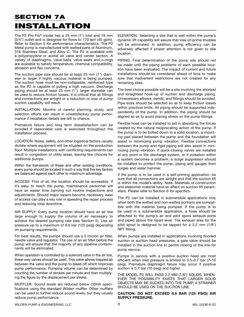
Suction lift curves are calibrated for pumps operating at 305 m (1,000') above sea level. This chart is meant to be a guide only. There are many variables which can affect your pump’s operating characteristics. The number of intake and
discharge elbows, viscosity of pumping fluid, elevation (atmo-spheric pressure) and pipe friction loss all affect the amount of suction lift your pump will attain.
PTFE Diaphragms
[0.7] [1.4] [2.0] [2.7] [3.4] [4.1] [4.8] [5.5] [6.2] [6.9]
8WILDEN PUMP & ENGINEERING, LLC WIL-10180-E-02
SECTION 7A
INSTALLATIONThe P2 Pro-Flo® model has a 25 mm (1") inlet and 19 mm (3/4") outlet and is designed for flows to 170 lpm (45 gpm). Refer to Section 5 for performance characteristics. The P2 Metal pump is manufactured with wetted parts of Aluminum, 316 Stainless Steel, and Alloy C. The P2 is available with a polypropylene or acetal air valve and center section. A variety of diaphragms, valve balls, valve seats and o-rings are available to satisfy temperature, chemical compatibility, abrasion and flex concerns.
The suction pipe size should be at least 25 mm (1") diam-eter or larger if highly viscous material is being pumped. The suction hose must be non-collapsible, reinforced type as the P2 is capable of pulling a high vacuum. Discharge piping should be at least 25 mm (1"); larger diameter can be used to reduce friction losses. It is critical that all fittings and connections are airtight or a reduction or loss of pump suction capability will result.
INSTALLATION: Months of careful planning, study, and selection efforts can result in unsatisfactory pump perfor-mance if installation details are left to chance.
Premature failure and long term dissatisfaction can be avoided if reasonable care is exercised throughout the installation process.
LOCATION: Noise, safety, and other logistical factors usually dictate where equipment will be situated on the production floor. Multiple installations with conflicting requirements can result in congestion of utility areas, leaving few choices for additional pumps.
Within the framework of these and other existing conditions, every pump should be located in such a way that five key factors are balanced against each other to maximum advantage.
ACCESS: First of all, the location should be accessible. If it’s easy to reach the pump, maintenance personnel will have an easier time carrying out routine inspections and adjustments. Should major repairs become necessary, ease of access can play a key role in speeding the repair process and reducing total downtime.
AIR SUPPLY: Every pump location should have an air line large enough to supply the volume of air necessary to achieve the desired pumping rate (see Section 5). Use air pressure up to a maximum of 8.6 bar (125 psig) depending on pumping requirements.
For best results, the pumps should use a 5 micron air filter, needle valve and regulator. The use of an air filter before the pump will ensure that the majority of any pipeline contami-nants will be eliminated.
When operation is controlled by a solenoid valve in the air line, three-way valves should be used. This valve allows trapped air between the valve and the pump to bleed off which improves pump performance. Pumping volume can be determined by counting the number of strokes per minute and then multiply-ing the figure by the displacement per stroke.
MUFFLER: Sound levels are reduced below OSHA speci-fications using the standard Wilden muffler. Other mufflers can be used to further reduce sound levels, but they usually reduce pump performance.
ELEVATION: Selecting a site that is well within the pump’s dynamic lift capability will assure that loss-of-prime troubles will be eliminated. In addition, pump efficiency can be adversely affected if proper attention is not given to site location.
PIPING: Final determination of the pump site should not be made until the piping problems of each possible loca-tion have been evaluated. The impact of current and future installations should be considered ahead of time to make sure that inadvertent restrictions are not created for any remaining sites.
The best choice possible will be a site involving the shortest and straightest hook-up of suction and discharge piping. Unnecessary elbows, bends, and fittings should be avoided. Pipe sizes should be selected so as to keep friction losses within practical limits. All piping should be supported inde-pendently of the pump. In addition, the piping should be aligned so as to avoid placing stress on the pump fittings.
Flexible hose can be installed to aid in absorbing the forces created by the natural reciprocating action of the pump. If the pump is to be bolted down to a solid location, a mount-ing pad placed between the pump and the foundation will assist in minimizing pump vibration. Flexible connections between the pump and rigid piping will also assist in mini-mizing pump vibration. If quick-closing valves are installed at any point in the discharge system, or if pulsation within a system becomes a problem, a surge suppressor should be installed to protect the pump, piping and gauges from surges and water hammer.
If the pump is to be used in a self-priming application, be sure that all connections are airtight and that the suction lift is within the model’s ability. Note: Materials of construction and elastomer material have an effect on suction lift param-eters. Please refer to Section 6 for specifics.
The P2 can be installed in submersible applications only when both the wetted and non-wetted portions are compat-ible with the material being pumped. If the pump is to be used in a submersible application, a hose should be attached to the pump’s air and pilot spool exhaust ports and piped above the liquid level. The exhaust area for the pilot spool is designed to be tapped for a 3.2 mm (1/8") NPT fitting.
When pumps are installed in applications involving flooded suction or suction head pressures, a gate valve should be installed in the suction line to permit closing of the line for pump service.
Pumps in service with a positive suction head are most efficient when inlet pressure is limited to 0.5–0.7 bar (7–10 psig). Premature diaphragm failure may occur if positive suction is 0.7 bar (10 psig) and higher.
THE MODEL P2 WILL PASS 3.2 MM (1/8") SOLIDS. WHEN-EVER THE POSSIBILITY EXISTS THAT LARGER SOLID OBJECTS MAY BE SUCKED INTO THE PUMP, A STRAINER SHOULD BE USED ON THE SUCTION LINE.
CAUTION: DO NOT EXCEED 8.6 BAR (125 PSIG) AIR SUPPLY PRESSURE.
9 WILDEN PUMP & ENGINEERING, LLCWIL-10180-E-02
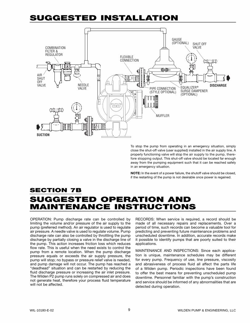
SUGGESTED INSTALLATION
SECTION 7B
SUGGESTED OPERATION ANDMAINTENANCE INSTRUCTIONS
To stop the pump from operating in an emergency situation, simply close the shut-off valve (user supplied) installed in the air supply line. A properly functioning valve will stop the air supply to the pump, there-fore stopping output. This shut-off valve should be located far enough away from the pumping equipment such that it can be reached safely in an emergency situation.
NOTE: In the event of a power failure, the shutoff valve should be closed, if the restarting of the pump is not desirable once power is regained.
SUCTION
AIRSHUTOFFVALVE
FLEXIBLECONNECTION
COMBINATIONFILTER ®ULATOR
NEEDLEVALVE PIPE CONNECTION
(STYLE OPTIONAL)EQUALIZERSURGE DAMPENER(OPTIONAL)
DISCHARGE
SHUT OFFVALVE
GAUGE(OPTIONAL)
MUFFLER
®
OPERATION: Pump discharge rate can be controlled by limiting the volume and/or pressure of the air supply to the pump (preferred method). An air regulator is used to regulate air pressure. A needle valve is used to regulate volume. Pump discharge rate can also be controlled by throttling the pump discharge by partially closing a valve in the discharge line of the pump. This action increases friction loss which reduces flow rate. This is useful when the need exists to control the pump from a remote location. When the pump discharge pressure equals or exceeds the air supply pressure, the pump will stop; no bypass or pressure relief valve is needed, and pump damage will not occur. The pump has reached a “deadhead” situation and can be restarted by reducing the fluid discharge pressure or increasing the air inlet pressure. The Wilden P2 pump runs solely on compressed air and does not generate heat, therefore your process fluid temperature will not be affected.
RECORDS: When service is required, a record should be made of all necessary repairs and replacements. Over a period of time, such records can become a valuable tool for predicting and preventing future maintenance problems and unscheduled downtime. In addition, accurate records make it possible to identify pumps that are poorly suited to their applications.
MAINTENANCE AND INSPECTIONS: Since each applica-tion is unique, maintenance schedules may be different for every pump. Frequency of use, line pressure, viscosity and abrasiveness of process fluid all affect the parts life of a Wilden pump. Periodic inspections have been found to offer the best means for preventing unscheduled pump downtime. Personnel familiar with the pump’s construction and service should be informed of any abnormalities that are detected during operation.
10WILDEN PUMP & ENGINEERING, LLC WIL-10180-E-02
SECTION 7C
TROUBLESHOOTINGPump will not run or runs slowly.1. Ensure that the air inlet pressure is at least 0.4 bar (5 psig)
above startup pressure and that the differential pressure (the difference between air inlet and liquid discharge pressures) is not less than 0.7 bar (10 psig).
2. Check air inlet filter for debris (see recommended installation).
3. Check for extreme air leakage (blow by) which would indicate worn seals/bores in the air valve, pilot spool, main shaft.
4. Disassemble pump and check for obstructions in the air passageways or objects which would obstruct the movement of internal parts.
5. Check for sticking ball check valves. If material being pumped is not compatible with pump elastomers, swell-ing may occur. Replace ball check valves and seals with proper elastomers. Also, as the check valve balls wear out, they become smaller and can become stuck in the seats. In this case, replace balls and seats.
6. Check for broken inner piston which will cause the air valve spool to be unable to shift.
7. Remove plug from pilot spool exhaust.
Pump runs but little or no product flows.1. Check for pump cavitation; slow pump speed down to
allow thick material to flow into liquid chambers.2. Verify that vacuum required to lift liquid is not greater than
the vapor pressure of the material being pumped (cavita-tion).
3. Check for sticking ball check valves. If material being pumped is not compatible with pump elastomers, swell-ing may occur. Replace ball check valves and seals with proper elastomers. Also, as the check valve balls wear out, they become smaller and can become stuck in the seats. In this case, replace balls and seats.
Pump air valve freezes.1. Check for excessive moisture in compressed air. Either
install a dryer or hot air generator for compressed air. Alternatively, a coalescing filter may be used to remove the water from the compressed air in some applications.
Air bubbles in pump discharge.1. Check for ruptured diaphragm.2. Check tightness of outer pistons (refer to Section 8C).3. Check tightness of clamp bands and integrity of o-rings
and seals, especially at intake manifold.4. Ensure pipe connections are airtight.
Product comes out air exhaust.1. Check for diaphragm rupture.2. Check tightness of outer pistons to shaft.
11 WILDEN PUMP & ENGINEERING, LLCWIL-10180-E-02
SECTION 8A
P2 METALDIRECTIONS FOR DISASSEMBLY/REASSEMBLY
Figure 1
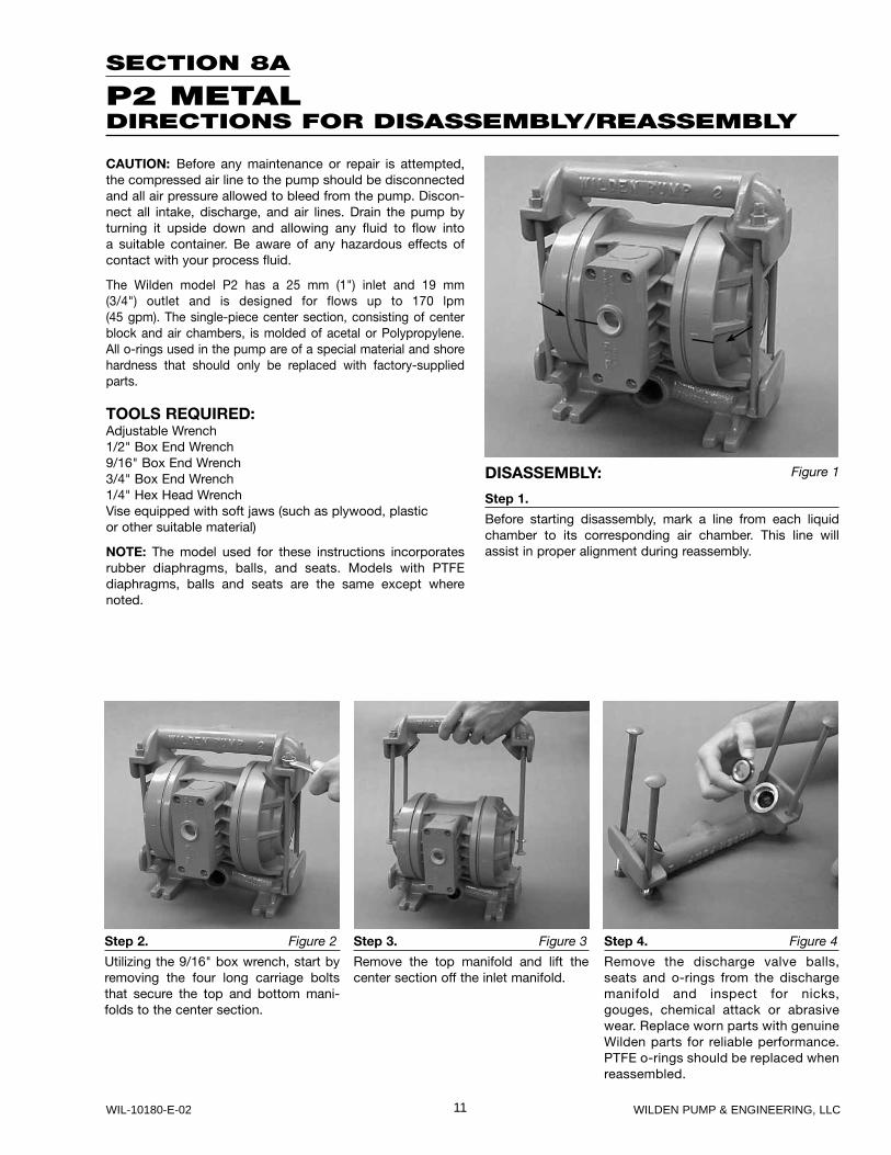
Step 2. Figure 2
Utilizing the 9/16" box wrench, start by removing the four long carriage bolts that secure the top and bottom mani-folds to the center section.
Step 3. Figure 3
Remove the top manifold and lift the center section off the inlet manifold.
Step 4. Figure 4
Remove the discharge valve balls, seats and o-rings from the discharge manifold and inspect for nicks, gouges, chemical attack or abrasive wear. Replace worn parts with genuine Wilden parts for reliable performance. PTFE o-rings should be replaced when reassembled.
CAUTION: Before any maintenance or repair is attempted, the compressed air line to the pump should be disconnected and all air pressure allowed to bleed from the pump. Discon-nect all intake, discharge, and air lines. Drain the pump by turning it upside down and allowing any fluid to flow into a suitable container. Be aware of any hazardous effects of contact with your process fluid.
The Wilden model P2 has a 25 mm (1") inlet and 19 mm (3/4") outlet and is designed for flows up to 170 lpm (45 gpm). The single-piece center section, consisting of center block and air chambers, is molded of acetal or Polypropylene. All o-rings used in the pump are of a special material and shore hardness that should only be replaced with factory-supplied parts.
TOOLS REQUIRED:Adjustable Wrench1/2" Box End Wrench9/16" Box End Wrench3/4" Box End Wrench1/4" Hex Head WrenchVise equipped with soft jaws (such as plywood, plasticor other suitable material)
NOTE: The model used for these instructions incorporates rubber diaphragms, balls, and seats. Models with PTFE diaphragms, balls and seats are the same except where noted.
DISASSEMBLY:
Step 1.
Before starting disassembly, mark a line from each liquid chamber to its corresponding air chamber. This line will assist in proper alignment during reassembly.
12WILDEN PUMP & ENGINEERING, LLC WIL-10180-E-02
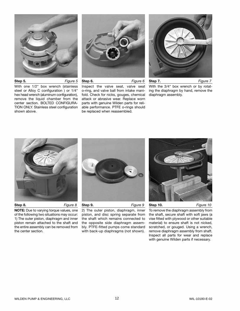
Step 10. Figure 10
To remove the diaphragm assembly from the shaft, secure shaft with soft jaws (a vise fitted with plywood or other suitable material) to ensure shaft is not nicked, scratched, or gouged. Using a wrench, remove diaphragm assembly from shaft. Inspect all parts for wear and replace with genuine Wilden parts if necessary.
Step 9. Figure 9
2) The outer piston, diaphragm, inner piston, and disc spring separate from the shaft which remains connected to the opposite side diaphragm assem-bly. PTFE-fitted pumps come standard with back-up diaphragms (not shown).
Step 8. Figure 8
NOTE: Due to varying torque values, one of the following two situations may occur: 1) The outer piston, diaphragm and inner piston remain attached to the shaft and the entire assembly can be removed from the center section.
Step 7. Figure 7
With the 3/4" box wrench or by rotat-ing the diaphragm by hand, remove the diaphragm assembly.
Step 6. Figure 6
Inspect the valve seat, valve seat o-ring, and valve ball from intake mani-fold. Check for nicks, gouges, chemical attack or abrasive wear. Replace worn parts with genuine Wilden parts for reli-able performance. PTFE o-rings should be replaced when reassembled.
Step 5. Figure 5
With one 1/2" box wrench (stainless steel or Alloy C configuration ) or 1/4" hex head wrench (aluminum configuration), remove the liquid chamber from the center section. BOLTED CONFIGURA-TION ONLY. Stainless steel configuration shown above.
13 WILDEN PUMP & ENGINEERING, LLCWIL-10180-E-02
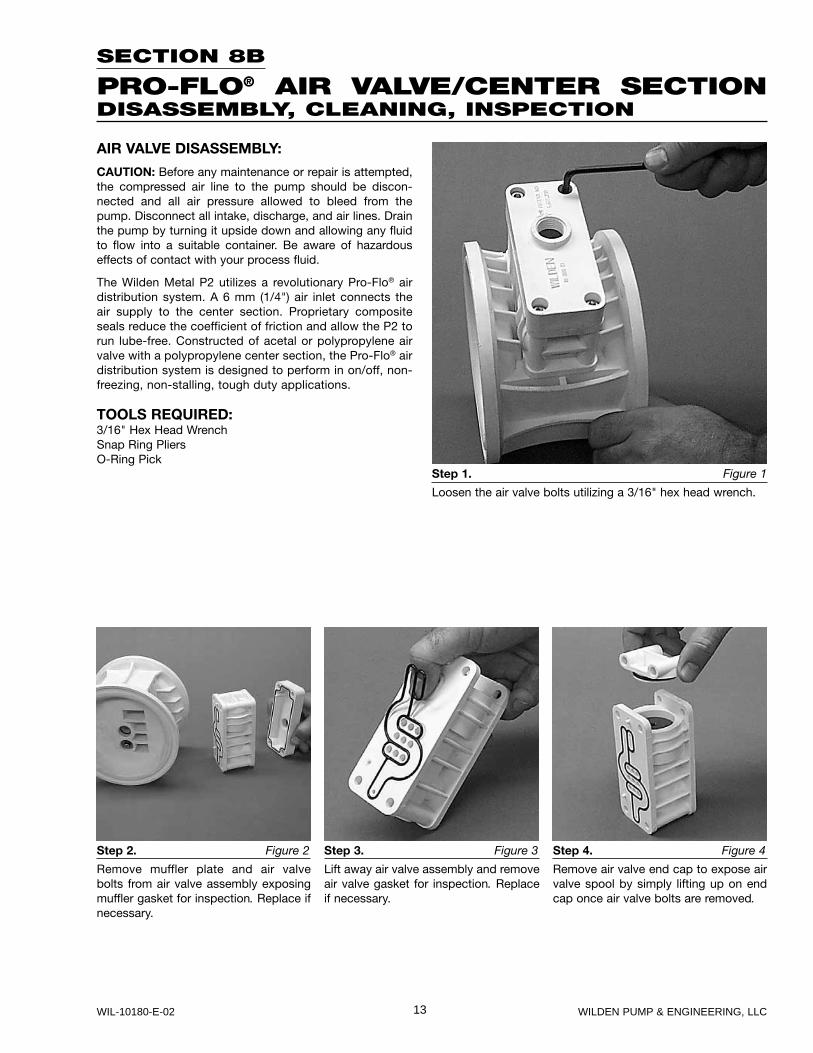
Step 2. Figure 2
Remove muffler plate and air valve bolts from air valve assembly exposing muffler gasket for inspection. Replace if necessary.
Step 3. Figure 3
Lift away air valve assembly and remove air valve gasket for inspection. Replace if necessary.
Step 4. Figure 4
Remove air valve end cap to expose air valve spool by simply lifting up on end cap once air valve bolts are removed.
SECTION 8B
PRO-FLO® AIR VALVE/CENTER SECTIONDISASSEMBLY, CLEANING, INSPECTION
Step 1. Figure 1
Loosen the air valve bolts utilizing a 3/16" hex head wrench.
AIR VALVE DISASSEMBLY:
CAUTION: Before any maintenance or repair is attempted, the compressed air line to the pump should be discon-nected and all air pressure allowed to bleed from the pump. Disconnect all intake, discharge, and air lines. Drain the pump by turning it upside down and allowing any fluid to flow into a suitable container. Be aware of hazardous effects of contact with your process fluid.
The Wilden Metal P2 utilizes a revolutionary Pro-Flo® air distribution system. A 6 mm (1/4") air inlet connects the air supply to the center section. Proprietary composite seals reduce the co efficient of friction and allow the P2 to run lube-free. Constructed of acetal or polypropylene air valve with a polypropylene center section, the Pro-Flo® air distribution system is designed to perform in on/off, non-freezing, non-stalling, tough duty applications.
TOOLS REQUIRED:3/16" Hex Head WrenchSnap Ring PliersO-Ring Pick
14WILDEN PUMP & ENGINEERING, LLC WIL-10180-E-02
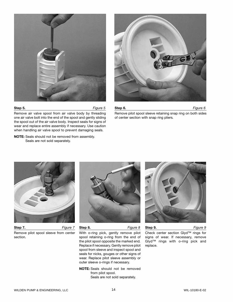
Step 7. Figure 7
Remove pilot spool sleeve from center section.
Step 8. Figure 8
With o-ring pick, gently remove pilot spool retaining o-ring from the end of the pilot spool opposite the marked end.Replace if necessary. Gently remove pilot spool from sleeve and inspect spool and seals for nicks, gouges or other signs of wear. Replace pilot sleeve assembly or outer sleeve o-rings if necessary.
NOTE: Seals should not be removed from pilot spool.
Seals are not sold separately.
Step 9. Figure 9
Check center section Glyd™ rings for signs of wear. If necessary, remove Glyd™ rings with o-ring pick and replace.
Step 5. Figure 5
Remove air valve spool from air valve body by threading one air valve bolt into the end of the spool and gently sliding the spool out of the air valve body. Inspect seals for signs of wear and replace entire assembly if necessary. Use caution when handling air valve spool to prevent damaging seals.
NOTE: Seals should not be removed from assembly.Seals are not sold separately.
Step 6. Figure 6
Remove pilot spool sleeve retaining snap ring on both sides of center section with snap ring pliers.
15 WILDEN PUMP & ENGINEERING, LLCWIL-10180-E-02
SECTION 8C
REASSEMBLY HINTS & TIPS
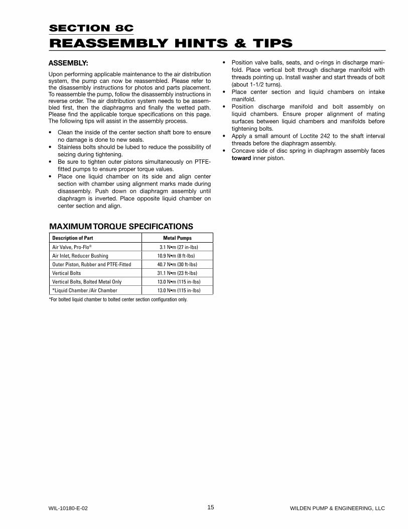
ASSEMBLY:Upon performing applicable maintenance to the air distribution system, the pump can now be reassembled. Please refer to the disassembly instructions for photos and parts placement. To reassemble the pump, follow the disassembly instructions in reverse order. The air distribution system needs to be assem-bled first, then the diaphragms and finally the wetted path. Please find the applicable torque specifications on this page. The following tips will assist in the assembly process.
• Clean the inside of the center section shaft bore to ensure no damage is done to new seals.
• Stainless bolts should be lubed to reduce the possibility of seizing during tightening.
• Be sure to tighten outer pistons simultaneously on PTFE-fitted pumps to ensure proper torque values.
• Place one liquid chamber on its side and align center section with chamber using alignment marks made during disassembly. Push down on diaphragm assembly until diaphragm is inverted. Place opposite liquid chamber on center section and align.
• Position valve balls, seats, and o-rings in discharge mani-fold. Place vertical bolt through discharge manifold with threads pointing up. Install washer and start threads of bolt (about 1-1/2 turns).
• Place center section and liquid chambers on intake manifold.
• Position discharge manifold and bolt assembly on liquid chambers. Ensure proper alignment of mating surfaces between liquid chambers and manifolds before tightening bolts.
• Apply a small amount of Loctite 242 to the shaft interval threads before the diaphragm assembly.
• Concave side of disc spring in diaphragm assembly faces toward inner piston.
MAXIMUM TORQUE SPECIFICATIONS
Description of Part Metal Pumps
Air Valve, Pro-Flo® 3.1 N•m (27 in-lbs)
Air Inlet, Reducer Bushing 10.9 N•m (8 ft-lbs)
Outer Piston, Rubber and PTFE-Fitted 40.7 N•m (30 ft-lbs)
Vertical Bolts 31.1 N•m (23 ft-lbs)
Vertical Bolts, Bolted Metal Only 13.0 N•m (115 in-lbs)
*Liquid Chamber /Air Chamber 13.0 N•m (115 in-lbs)
*For bolted liquid chamber to bolted center section configuration only.
16WILDEN PUMP & ENGINEERING, LLC WIL-10180-E-02
P2 Bolted
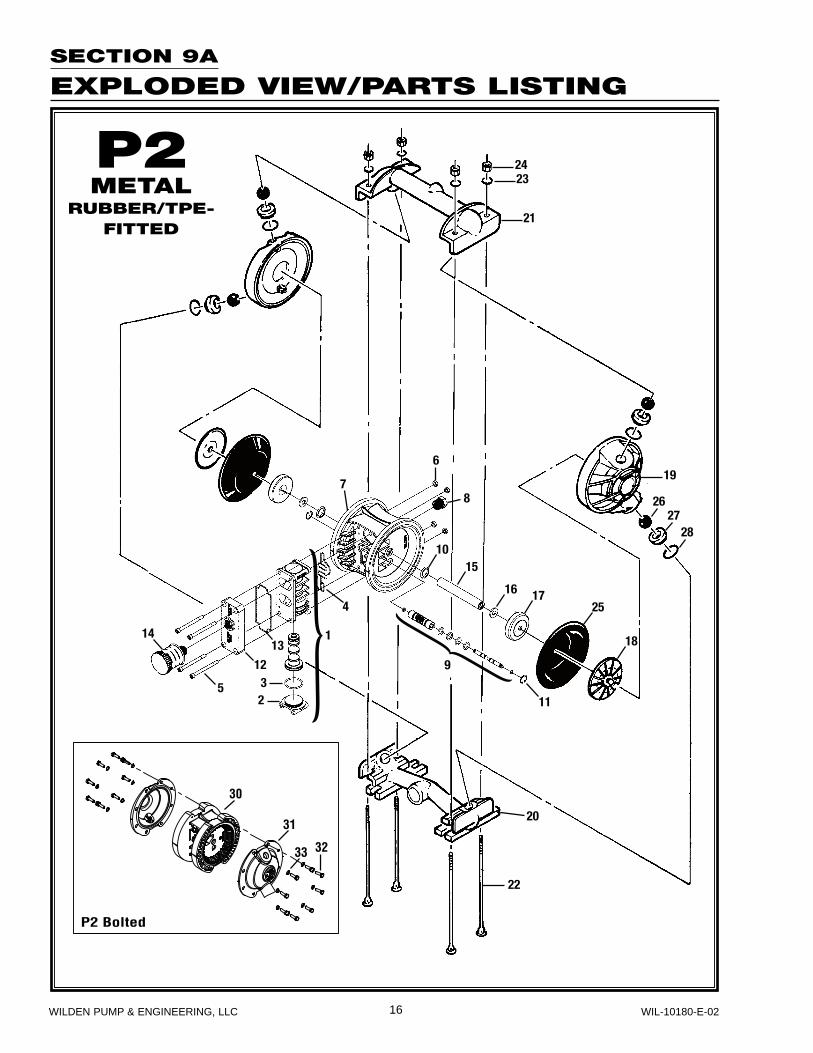
SECTION 9A
EXPLODED VIEW/PARTS LISTING
P2METAL
RUBBER/TPE-FITTED
17 WILDEN PUMP & ENGINEERING, LLCWIL-10180-E-02
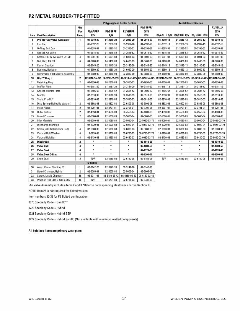
P2 METAL RUBBER/TPE-FITTED
Polypropylene Center Section Acetal Center Section
Item Part Description
QtyPer
PumpP2/AAPPP
P/NP2/SSPPP
P/NP2/HHPPP
P/N
P2/SSPPP/0070P/N P2/AALLL P/N P2/SSLLL P/N P2/ HHLLL P/N
P2/SSLLL/0070P/N
1 Pro-Flo® Air Valve Assembly1 1 01-2010-20 01-2010-20 01-2010-20 01-2010-20 01-2010-13 01-2010-13 01-2010-13 01-2010-13
2 End Cap 1 01-2332-20 01-2332-20 01-2332-20 01-2332-20 01-2332-13 01-2332-13 01-2332-13 01-2332-133 O-Ring, End Cap 1 01-2395-52 01-2395-52 01-2395-52 01-2395-52 01-2395-52 01-2395-52 01-2395-52 01-2395-524 Gasket, Air Valve 1 01-2615-52 01-2615-52 01-2615-52 01-2615-52 01-2615-52 01-2615-52 01-2615-52 01-2615-525 Screw, HSHC, Air Valve 1⁄4"-20 4 01-6001-03 01-6001-03 01-6001-03 01-6001-03 01-6001-03 01-6001-03 01-6001-03 01-6001-036 Nut, Hex, 1⁄4"-20 4 04-6400-03 04-6400-03 04-6400-03 04-6400-03 04-6400-03 04-6400-03 04-6400-03 04-6400-037 Center Section 1 02-3145-20 02-3145-20 02-3145-20 02-3145-20 02-3145-13 02-3145-13 02-3145-13 02-3145-138 Bushing, Reducer 1 01-6950-20 01-6950-20 01-6950-20 01-6950-20 01-6950-13 01-6950-13 01-6950-13 01-6950-139 Removable Pilot Sleeve Assembly 1 02-3880-99 02-3880-99 02-3880-99 02-3880-99 02-3880-99 02-3880-99 02-3880-99 02-3880-99
10 Glyd™ Ring II 2 02-3210-55-225 02-3210-55-225 02-3210-55-225 02-3210-55-225 02-3210-55-225 02-3210-55-225 02-3210-55-225 02-3210-55-225
11 Retaining Ring 2 00-2650-03 00-2650-03 00-2650-03 00-2650-03 00-2650-03 00-2650-03 00-2650-03 00-2650-0312 Muffler Plate 1 01-3181-20 01-3181-20 01-3181-20 01-3181-20 01-3181-13 01-3181-13 01-3181-13 01-3181-1313 Gasket, Muffler Plate 1 01-3505-52 01-3505-52 01-3505-52 01-3505-52 01-3505-52 01-3505-52 01-3505-52 01-3505-5214 Muffler 1 02-3510-99 02-3510-99 02-3510-99 02-3510-99 02-3510-99 02-3510-99 02-3510-99 02-3510-9915 Shaft, Pro-Flo® 1 02-3810-03 02-3810-03 02-3810-03 02-3810-03 02-3810-03 02-3810-03 02-3810-03 02-3810-0316 Disc Spring (Belleville Washer) 2 02-6802-08 02-6802-08 02-6802-08 02-6802-08 02-6802-08 02-6802-08 02-6802-08 02-6802-0817 Inner Piston 2 02-3701-01 02-3701-01 02-3701-01 02-3701-01 02-3701-01 02-3701-01 02-3701-01 02-3701-0118 Outer Piston 2 02-4550-01 02-4550-03 02-4550-04 02-4600-03 02-4550-01 02-4550-03 02-4550-04 02-4600-0319 Liquid Chamber 2 02-5000-01 02-5000-03 02-5000-04 02-5000-03 02-5000-01 02-5000-03 02-5000-04 02-5000-0320 Inlet Manifold 1 02-5080-01 02-5080-03 02-5080-04 02-5080-03-70 02-5080-01 02-5080-03 02-5080-04 02-5085-03-7021 Discharge Manifold 1 02-5020-01 02-5020-03 02-5020-04 02-5020-03-70 02-5020-01 02-5020-03 02-5020-04 02-5025-03-7022 Screw, SHCS (Chamber Bolt) 4 02-6080-08 02-6080-03 02-6080-03 02-6080-03 02-6080-08 02-6080-03 02-6080-03 02-6080-0323 Vertical Bolt Washer 4 15-6720-08 02-6730-03 02-6730-03 08-6720-07-70 15-6720-08 02-6730-03 02-6730-03 08-6720-07-7024 Vertical Bolt Nut 4 02-6430-08 02-6430-03 02-6430-03 02-6680-03-70 02-6430-08 02-6430-03 02-6430-03 02-6680-03-7025 Diaphragm 2 * * * 02-1010-56 * * * 02-1010-56
26 Valve Ball 4 * * * 02-1080-56 * * * 02-1080-56
27 Valve Seat 4 * * * 02-1120-03 * * * 02-1120-03
28 Valve Seat O-Ring 4 * * * 02-1200-56 * * * 02-1200-56
29 Shaft Stud 2 N/R 02-6150-08 02-6150-08 02-6150-08 N/R 02-6150-08 02-6150-08 02-6150-08
P2 Bolted
30 Assy., Center Section, P2 1 02-3142-20 02-3142-20 02-3142-20 02-3142-2031 Liquid Chamber, Hybrid 2 02-5005-01 02-5005-03 02-5005-04 02-5005-0332 Screw, Liquid Chamber 16 95-6011-08 08-6180-03-42 08-6180-03-42 08-6180-03-4233 Washer, Flat, .344 x .688 x .065 16 N/R 02-6731-03 02-6731-03 02-6731-03
1Air Valve Assembly includes items 2 and 3.*Refer to corresponding elastomer chart in Section 10.
NOTE: Item #6 is not required for bolted version.
Item numbers 30-33 for P2 Bolted confi guration.
0070 Specialty Code = Sanifl oFDA
0720 Specialty Code = Hybrid
0721 Specialty Code = Hybrid BSP
0722 Specialty Code = Hybrid Sanifl o (Not available with aluminum wetted components)
All boldface items are primary wear parts.
18WILDEN PUMP & ENGINEERING, LLC WIL-10180-E-02
31
3334
32
P2 Bolted
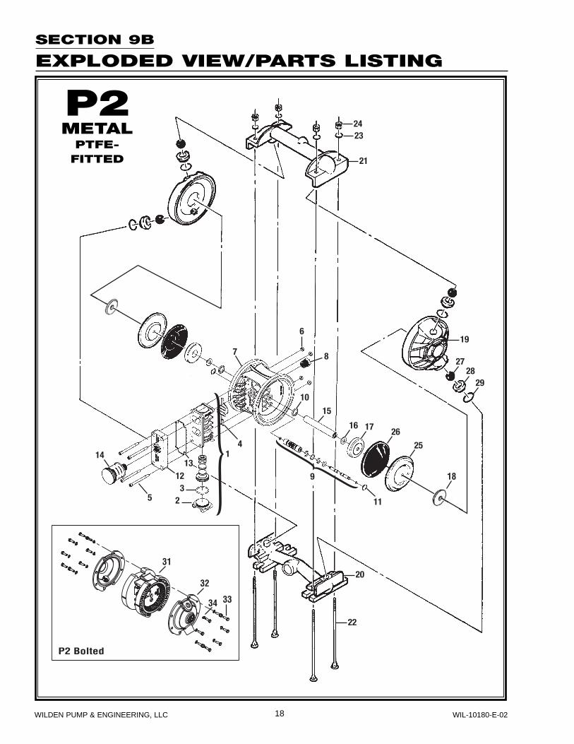
SECTION 9B
EXPLODED VIEW/PARTS LISTING
P2METAL
PTFE-FITTED
19 WILDEN PUMP & ENGINEERING, LLCWIL-10180-E-02
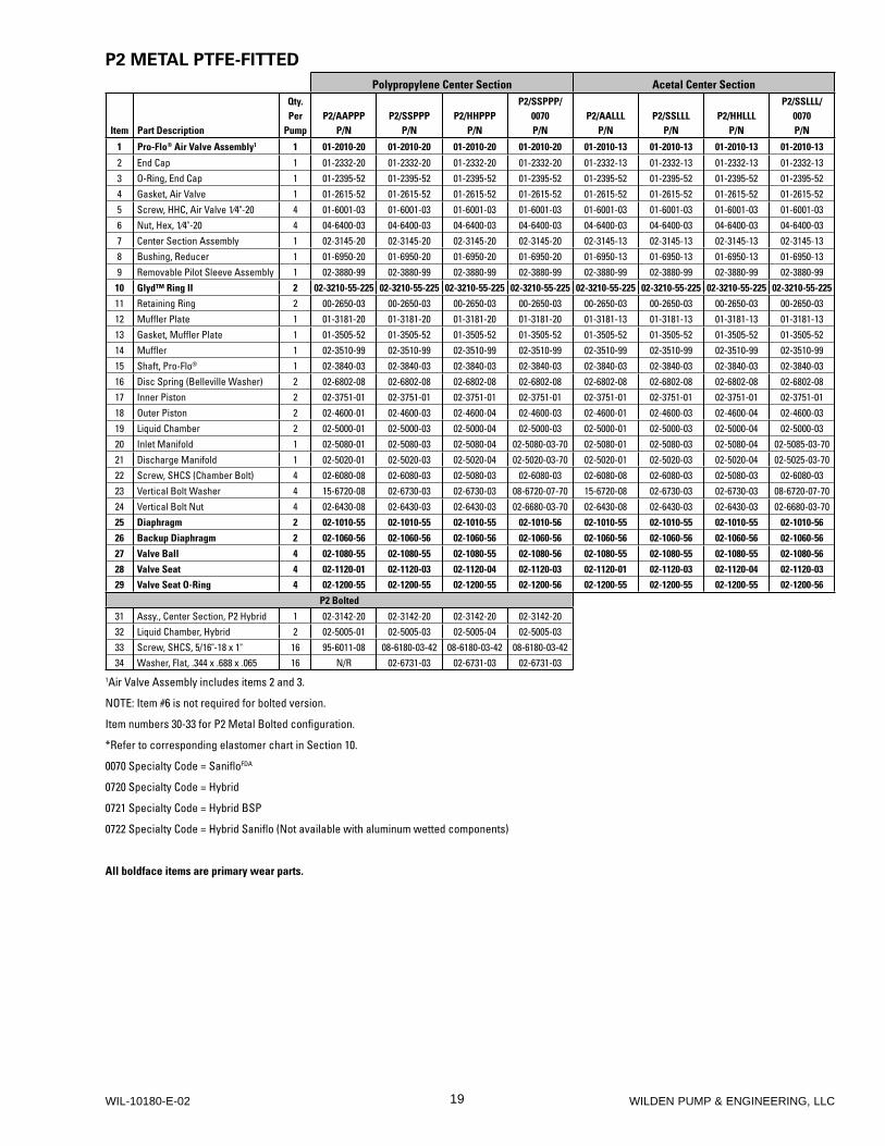
P2 METAL PTFE-FITTED
Polypropylene Center Section Acetal Center Section
Item Part Description
Qty. Per
PumpP2/AAPPP
P/NP2/SSPPP
P/NP2/HHPPP
P/N
P2/SSPPP/0070P/N
P2/AALLLP/N
P2/SSLLLP/N
P2/HHLLLP/N
P2/SSLLL/0070P/N
1 Pro-Flo® Air Valve Assembly1 1 01-2010-20 01-2010-20 01-2010-20 01-2010-20 01-2010-13 01-2010-13 01-2010-13 01-2010-13
2 End Cap 1 01-2332-20 01-2332-20 01-2332-20 01-2332-20 01-2332-13 01-2332-13 01-2332-13 01-2332-133 O-Ring, End Cap 1 01-2395-52 01-2395-52 01-2395-52 01-2395-52 01-2395-52 01-2395-52 01-2395-52 01-2395-524 Gasket, Air Valve 1 01-2615-52 01-2615-52 01-2615-52 01-2615-52 01-2615-52 01-2615-52 01-2615-52 01-2615-525 Screw, HHC, Air Valve 1⁄4"-20 4 01-6001-03 01-6001-03 01-6001-03 01-6001-03 01-6001-03 01-6001-03 01-6001-03 01-6001-036 Nut, Hex, 1⁄4"-20 4 04-6400-03 04-6400-03 04-6400-03 04-6400-03 04-6400-03 04-6400-03 04-6400-03 04-6400-037 Center Section Assembly 1 02-3145-20 02-3145-20 02-3145-20 02-3145-20 02-3145-13 02-3145-13 02-3145-13 02-3145-138 Bushing, Reducer 1 01-6950-20 01-6950-20 01-6950-20 01-6950-20 01-6950-13 01-6950-13 01-6950-13 01-6950-139 Removable Pilot Sleeve Assembly 1 02-3880-99 02-3880-99 02-3880-99 02-3880-99 02-3880-99 02-3880-99 02-3880-99 02-3880-99
10 Glyd™ Ring II 2 02-3210-55-225 02-3210-55-225 02-3210-55-225 02-3210-55-225 02-3210-55-225 02-3210-55-225 02-3210-55-225 02-3210-55-225
11 Retaining Ring 2 00-2650-03 00-2650-03 00-2650-03 00-2650-03 00-2650-03 00-2650-03 00-2650-03 00-2650-0312 Muffler Plate 1 01-3181-20 01-3181-20 01-3181-20 01-3181-20 01-3181-13 01-3181-13 01-3181-13 01-3181-1313 Gasket, Muffler Plate 1 01-3505-52 01-3505-52 01-3505-52 01-3505-52 01-3505-52 01-3505-52 01-3505-52 01-3505-5214 Muffler 1 02-3510-99 02-3510-99 02-3510-99 02-3510-99 02-3510-99 02-3510-99 02-3510-99 02-3510-9915 Shaft, Pro-Flo® 1 02-3840-03 02-3840-03 02-3840-03 02-3840-03 02-3840-03 02-3840-03 02-3840-03 02-3840-0316 Disc Spring (Belleville Washer) 2 02-6802-08 02-6802-08 02-6802-08 02-6802-08 02-6802-08 02-6802-08 02-6802-08 02-6802-0817 Inner Piston 2 02-3751-01 02-3751-01 02-3751-01 02-3751-01 02-3751-01 02-3751-01 02-3751-01 02-3751-0118 Outer Piston 2 02-4600-01 02-4600-03 02-4600-04 02-4600-03 02-4600-01 02-4600-03 02-4600-04 02-4600-0319 Liquid Chamber 2 02-5000-01 02-5000-03 02-5000-04 02-5000-03 02-5000-01 02-5000-03 02-5000-04 02-5000-0320 Inlet Manifold 1 02-5080-01 02-5080-03 02-5080-04 02-5080-03-70 02-5080-01 02-5080-03 02-5080-04 02-5085-03-7021 Discharge Manifold 1 02-5020-01 02-5020-03 02-5020-04 02-5020-03-70 02-5020-01 02-5020-03 02-5020-04 02-5025-03-7022 Screw, SHCS (Chamber Bolt) 4 02-6080-08 02-6080-03 02-5080-03 02-6080-03 02-6080-08 02-6080-03 02-5080-03 02-6080-0323 Vertical Bolt Washer 4 15-6720-08 02-6730-03 02-6730-03 08-6720-07-70 15-6720-08 02-6730-03 02-6730-03 08-6720-07-7024 Vertical Bolt Nut 4 02-6430-08 02-6430-03 02-6430-03 02-6680-03-70 02-6430-08 02-6430-03 02-6430-03 02-6680-03-7025 Diaphragm 2 02-1010-55 02-1010-55 02-1010-55 02-1010-56 02-1010-55 02-1010-55 02-1010-55 02-1010-56
26 Backup Diaphragm 2 02-1060-56 02-1060-56 02-1060-56 02-1060-56 02-1060-56 02-1060-56 02-1060-56 02-1060-56
27 Valve Ball 4 02-1080-55 02-1080-55 02-1080-55 02-1080-56 02-1080-55 02-1080-55 02-1080-55 02-1080-56
28 Valve Seat 4 02-1120-01 02-1120-03 02-1120-04 02-1120-03 02-1120-01 02-1120-03 02-1120-04 02-1120-03
29 Valve Seat O-Ring 4 02-1200-55 02-1200-55 02-1200-55 02-1200-56 02-1200-55 02-1200-55 02-1200-55 02-1200-56
P2 Bolted
31 Assy., Center Section, P2 Hybrid 1 02-3142-20 02-3142-20 02-3142-20 02-3142-2032 Liquid Chamber, Hybrid 2 02-5005-01 02-5005-03 02-5005-04 02-5005-0333 Screw, SHCS, 5/16"-18 x 1" 16 95-6011-08 08-6180-03-42 08-6180-03-42 08-6180-03-4234 Washer, Flat, .344 x .688 x .065 16 N/R 02-6731-03 02-6731-03 02-6731-03
1Air Valve Assembly includes items 2 and 3.
NOTE: Item #6 is not required for bolted version.
Item numbers 30-33 for P2 Metal Bolted confi guration.
*Refer to corresponding elastomer chart in Section 10.
0070 Specialty Code = Sanifl oFDA
0720 Specialty Code = Hybrid
0721 Specialty Code = Hybrid BSP
0722 Specialty Code = Hybrid Sanifl o (Not available with aluminum wetted components)
All boldface items are primary wear parts.
20WILDEN PUMP & ENGINEERING, LLC
WIL-10180-E-02
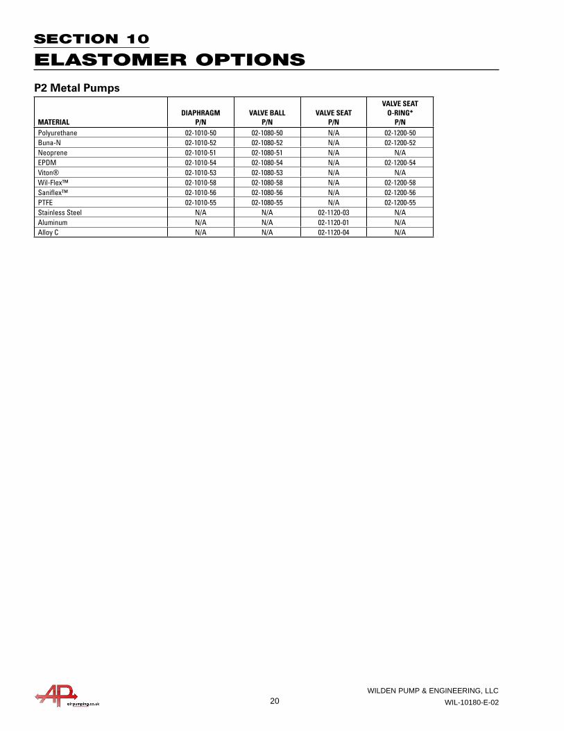
SECTION 10
ELASTOMER OPTIONS
P2 Metal Pumps
MATERIALDIAPHRAGM
P/NVALVE BALL
P/NVALVE SEAT
P/N
VALVE SEAT O-RING*
P/NPolyurethane 02-1010-50 02-1080-50 N/A 02-1200-50Buna-N 02-1010-52 02-1080-52 N/A 02-1200-52Neoprene 02-1010-51 02-1080-51 N/A N/AEPDM 02-1010-54 02-1080-54 N/A 02-1200-54Viton® 02-1010-53 02-1080-53 N/A N/AWil-Flex™ 02-1010-58 02-1080-58 N/A 02-1200-58Sanifl ex™ 02-1010-56 02-1080-56 N/A 02-1200-56PTFE 02-1010-55 02-1080-55 N/A 02-1200-55Stainless Steel N/A N/A 02-1120-03 N/AAluminum N/A N/A 02-1120-01 N/AAlloy C N/A N/A 02-1120-04 N/A
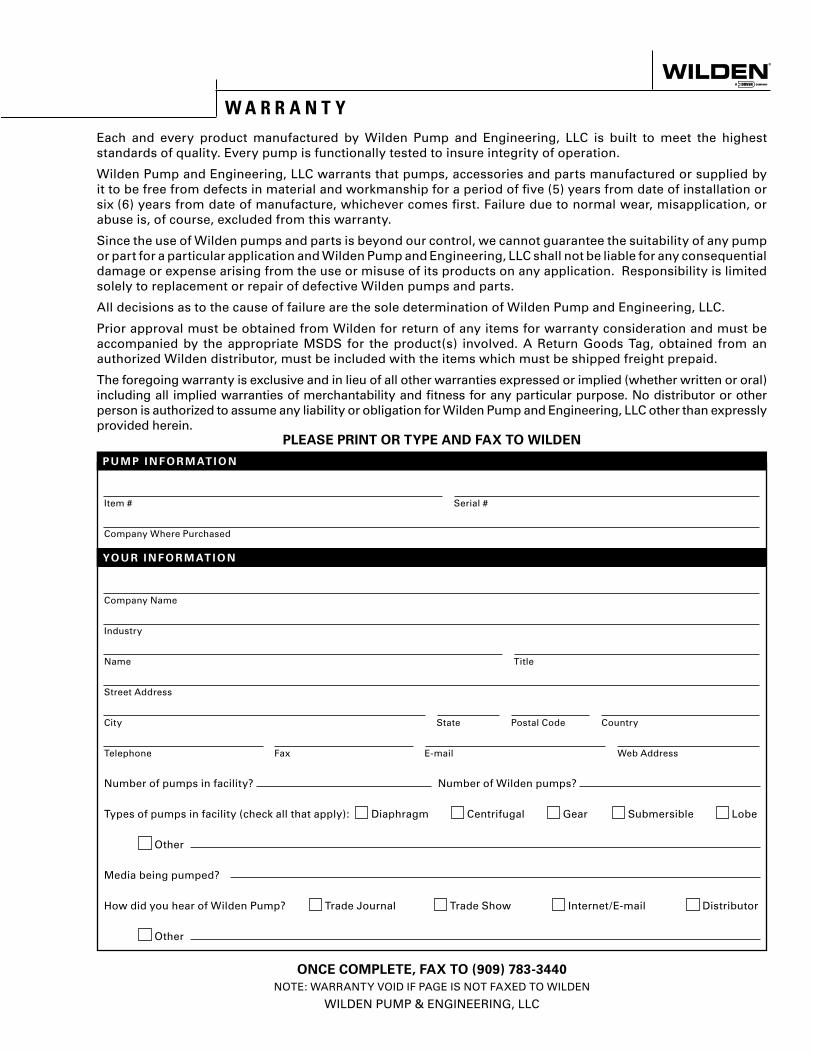
Item # Serial #
Company Where Purchased
Company Name
Industry
Name Title
Street Address
City State Postal Code Country
Telephone Fax E-mail Web Address
Number of pumps in facility? Number of Wilden pumps?
Types of pumps in facility (check all that apply): Diaphragm Centrifugal Gear Submersible Lobe
Other
Media being pumped?
How did you hear of Wilden Pump? Trade Journal Trade Show Internet/E-mail Distributor
Other
P U M P I N F O R M AT I O N
PLEASE PRINT OR TYPE AND FAX TO WILDEN
YO U R I N F O R M AT I O N
ONCE COMPLETE, FAX TO (909) 783-3440
NOTE: WARRANTY VOID IF PAGE IS NOT FAXED TO WILDEN
WILDEN PUMP & ENGINEERING, LLC
W A R R A N T YEach and every product manufactured by Wilden Pump and Engineering, LLC is built to meet the highest standards of quality. Every pump is functionally tested to insure integrity of operation.
Wilden Pump and Engineering, LLC warrants that pumps, accessories and parts manufactured or supplied by it to be free from defects in material and workmanship for a period of five (5) years from date of installation or six (6) years from date of manufacture, whichever comes first. Failure due to normal wear, misapplication, or abuse is, of course, excluded from this warranty.
Since the use of Wilden pumps and parts is beyond our control, we cannot guarantee the suitability of any pump or part for a particular application and Wilden Pump and Engineering, LLC shall not be liable for any consequential damage or expense arising from the use or misuse of its products on any application. Responsibility is limited solely to replacement or repair of defective Wilden pumps and parts.
All decisions as to the cause of failure are the sole determination of Wilden Pump and Engineering, LLC.
Prior approval must be obtained from Wilden for return of any items for warranty consideration and must be accompanied by the appropriate MSDS for the product(s) involved. A Return Goods Tag, obtained from an authorized Wilden distributor, must be included with the items which must be shipped freight prepaid.
The foregoing warranty is exclusive and in lieu of all other warranties expressed or implied (whether written or oral) including all implied warranties of merchantability and fitness for any particular purpose. No distributor or other person is authorized to assume any liability or obligation for Wilden Pump and Engineering, LLC other than expressly provided herein.