overview on compton polarimetry · specific polarimeter studies ... overview on compton polarimetry...
TRANSCRIPT

K. Peter SchülerOverview on Compton Polarimetry 1
SLAC – Jan. 6-8, 2005 ILC MDI - Workshop
General IssuesO spin motion & alignment tolerancesO beam-beam effects & upstream vs. Downstream
Compton Polarimetry BasicsO beam parameters & Compton detection methodsO kinematics, cross sections & asymmetriesO laser choices and parameters
Specific Polarimeter StudiesO upstream polarimeter study (DESY)O downstream polarimeter study (SLAC)
Overview on Compton Polarimetry
K. Peter SchülerOverview on Compton Polarimetry 2
SLAC – Jan. 6-8, 2005 ILC MDI - Workshop
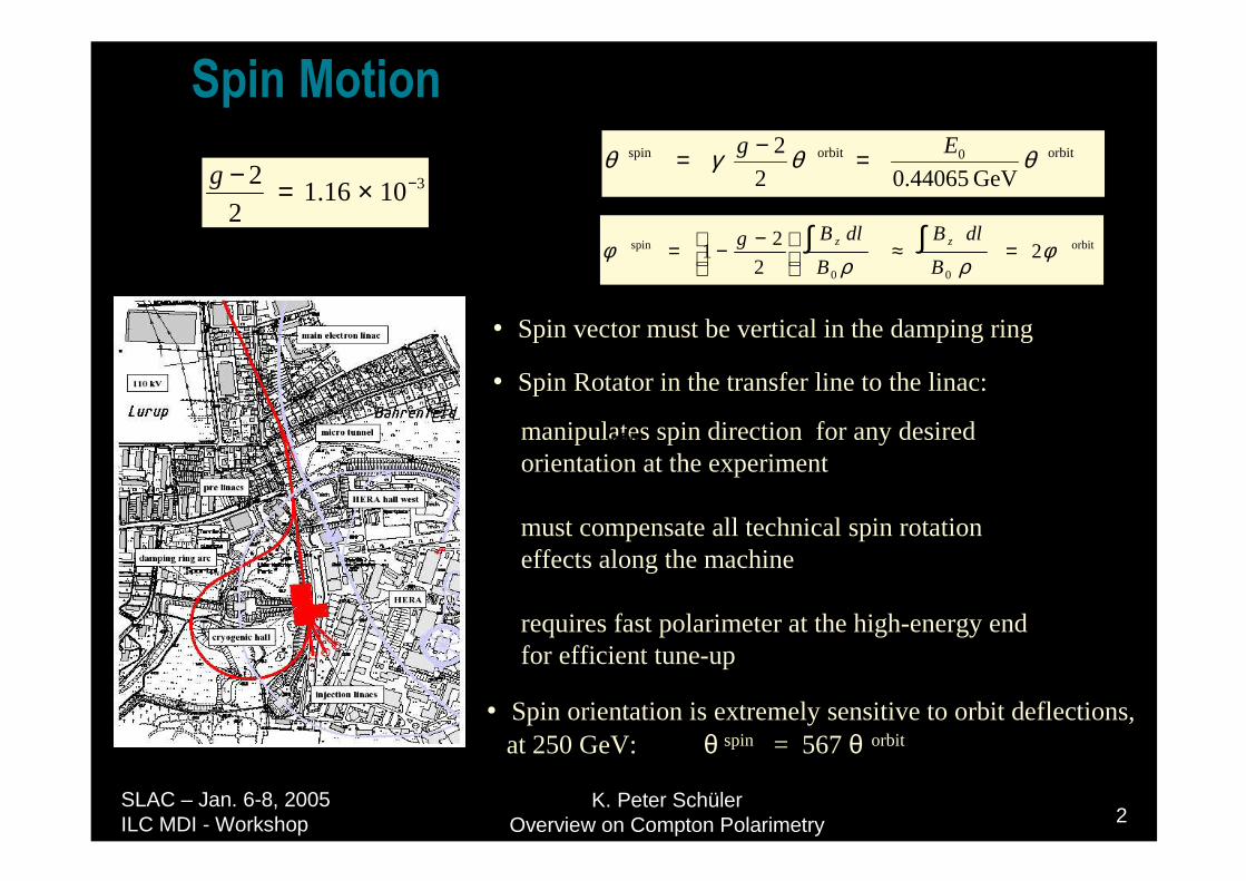
6SLQ�0RWLRQ
• Spin vector must be vertical in the damping ring
• Spin Rotator in the transfer line to the linac:
manipulates spin direction for any desired orientation at the experiment
must compensate all technical spin rotation effects along the machine
requires fast polarimeter at the high-energy end for efficient tune-up
θθ
orbitorbitspin
GeV
Eg θθγθ44065.02
2 0=−= orbitorbitspin
GeV
Eg θθγθ44065.02
2 0=−=
θ pinsθθpinθθ
orbit0orbitspin
GeV44065.02
2 θθγθ Eg =−=
orbit
00
spin 22
21 φ
ρρφ =≈
−−= ∫∫
B
dlB
B
dlBg zz
31016.12
2 −×=−g
• Spin orientation is extremely sensitive to orbit deflections,at 250 GeV: θ spin = 567 θ orbit
K. Peter SchülerOverview on Compton Polarimetry 3
SLAC – Jan. 6-8, 2005 ILC MDI - Workshop
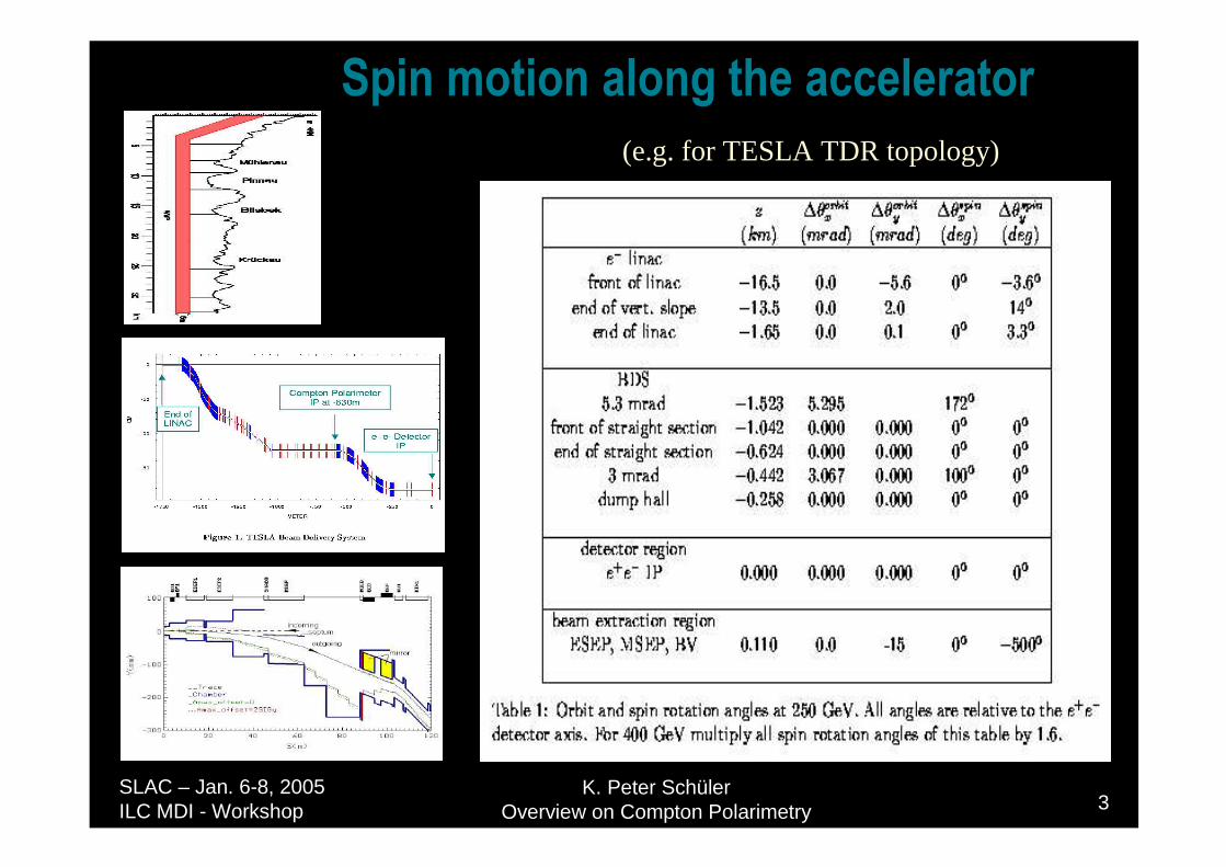
6SLQ�PRWLRQ�DORQJ�WKH�DFFHOHUDWRU(e.g. for TESLA TDR topology)
K. Peter SchülerOverview on Compton Polarimetry 4
SLAC – Jan. 6-8, 2005 ILC MDI - Workshop
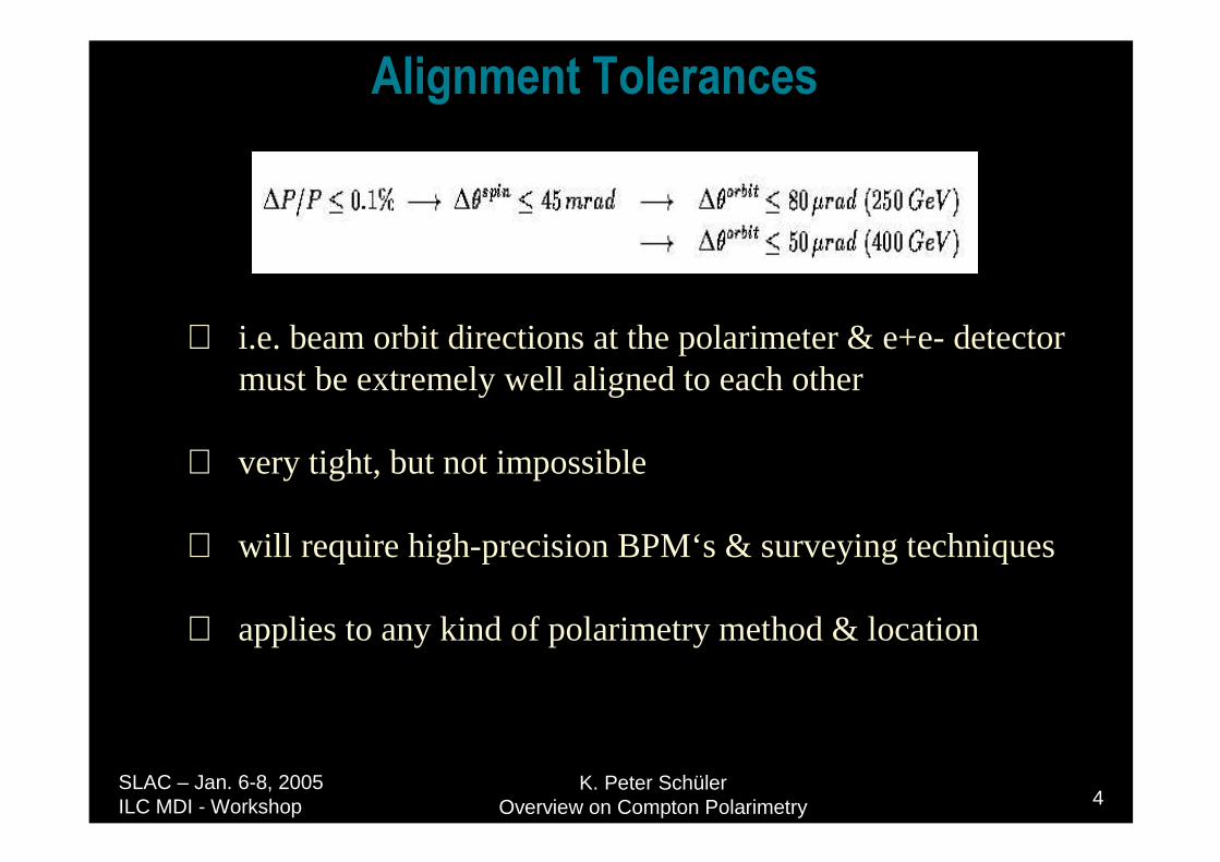
$OLJQPHQW�7ROHUDQFHV
⇒ i.e. beam orbit directions at the polarimeter & e+e- detector must be extremely well aligned to each other
⇒ very tight, but not impossible
⇒ will require high-precision BPM‘s & surveying techniques
⇒ applies to any kind of polarimetry method & location
K. Peter SchülerOverview on Compton Polarimetry 5
SLAC – Jan. 6-8, 2005 ILC MDI - Workshop
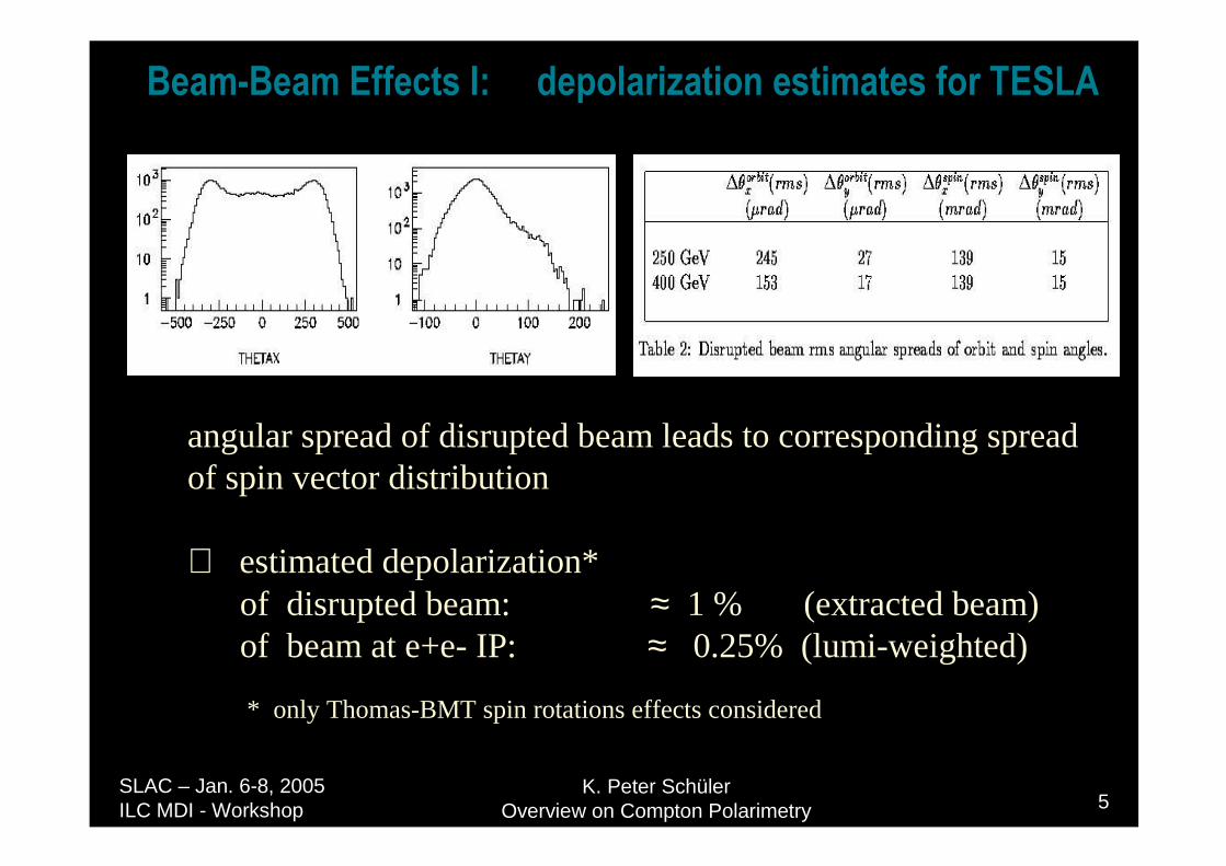
%HDP�%HDP�(IIHFWV�,������GHSRODUL]DWLRQ�HVWLPDWHV�IRU�7(6/$
angular spread of disrupted beam leads to corresponding spreadof spin vector distribution
⇒ estimated depolarization*of disrupted beam: ≈ 1 % (extracted beam)of beam at e+e- IP: ≈ 0.25% (lumi-weighted)
* only Thomas-BMT spin rotations effects considered
K. Peter SchülerOverview on Compton Polarimetry 6
SLAC – Jan. 6-8, 2005 ILC MDI - Workshop
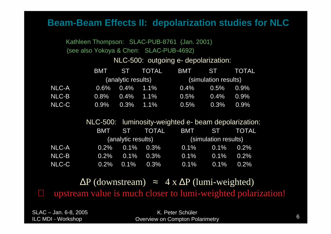
Kathleen Thompson: SLAC-PUB-8761 (Jan. 2001)(see also Yokoya & Chen: SLAC-PUB-4692)
NLC-500: outgoing e- depolarization:
BMT ST TOTAL BMT ST TOTAL(analytic results) (simulation results)
NLC-A 0.6% 0.4% 1.1% 0.4% 0.5% 0.9%NLC-B 0.8% 0.4% 1.1% 0.5% 0.4% 0.9%NLC-C 0.9% 0.3% 1.1% 0.5% 0.3% 0.9%
NLC-500: luminosity-weighted e- beam depolarization:BMT ST TOTAL BMT ST TOTAL
(analytic results) (simulation results)NLC-A 0.2% 0.1% 0.3% 0.1% 0.1% 0.2%NLC-B 0.2% 0.1% 0.3% 0.1% 0.1% 0.2%NLC-C 0.2% 0.1% 0.3% 0.1% 0.1% 0.2%
∆P (downstream) ≈ 4 x ∆P (lumi-weighted)⇒ upstream value is much closer to lumi-weighted polarization!
Beam-Beam Effects II: depolarization studies for NLC
K. Peter SchülerOverview on Compton Polarimetry 7
SLAC – Jan. 6-8, 2005 ILC MDI - Workshop
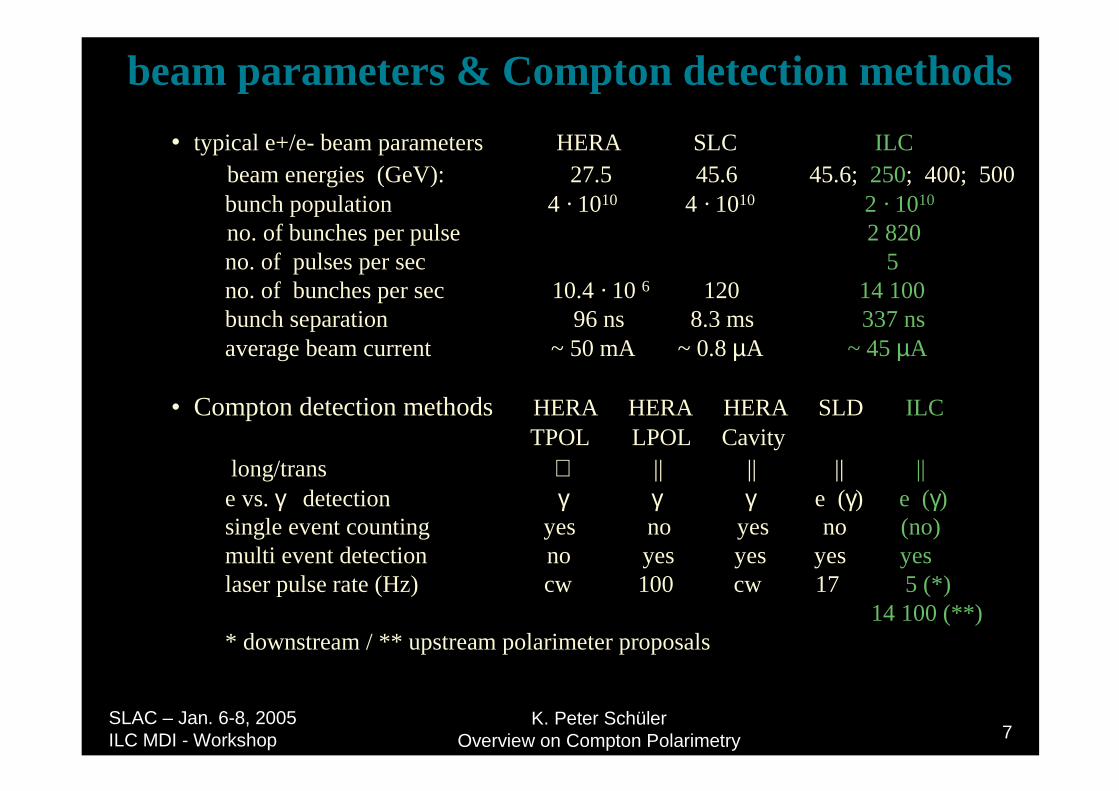
beam parameters & Compton detection methods
• typical e+/e- beam parameters HERA SLC ILCbeam energies (GeV): 27.5 45.6 45.6; 250; 400; 500 bunch population 4 · 1010 4 · 1010 2 · 1010
no. of bunches per pulse 2 820 no. of pulses per sec 5 no. of bunches per sec 10.4 · 10 6 120 14 100 bunch separation 96 ns 8.3 ms 337 nsaverage beam current ~ 50 mA ~ 0.8 µA ~ 45 µA
• Compton detection methods HERA HERA HERA SLD ILCTPOL LPOL Cavity
long/trans ⊥ || || || ||e vs. γ detection γ γ γ e (γ) e (γ)single event counting yes no yes no (no)multi event detection no yes yes yes yeslaser pulse rate (Hz) cw 100 cw 17 5 (*)
14 100 (**)* downstream / ** upstream polarimeter proposals
K. Peter SchülerOverview on Compton Polarimetry 8
SLAC – Jan. 6-8, 2005 ILC MDI - Workshop
&RPSWRQ�.LQHPDWLFV

K. Peter SchülerOverview on Compton Polarimetry 9
SLAC – Jan. 6-8, 2005 ILC MDI - Workshop
- 1 < P < + 1
- 1 < λ < + 1
&RPSWRQ�3RODULPHWU\
cross sections,spin asymmetry,scattering angles

K. Peter SchülerOverview on Compton Polarimetry 10
SLAC – Jan. 6-8, 2005 ILC MDI - Workshop
standard detection method:scattered electron detection with suitable magnetic spectrometer
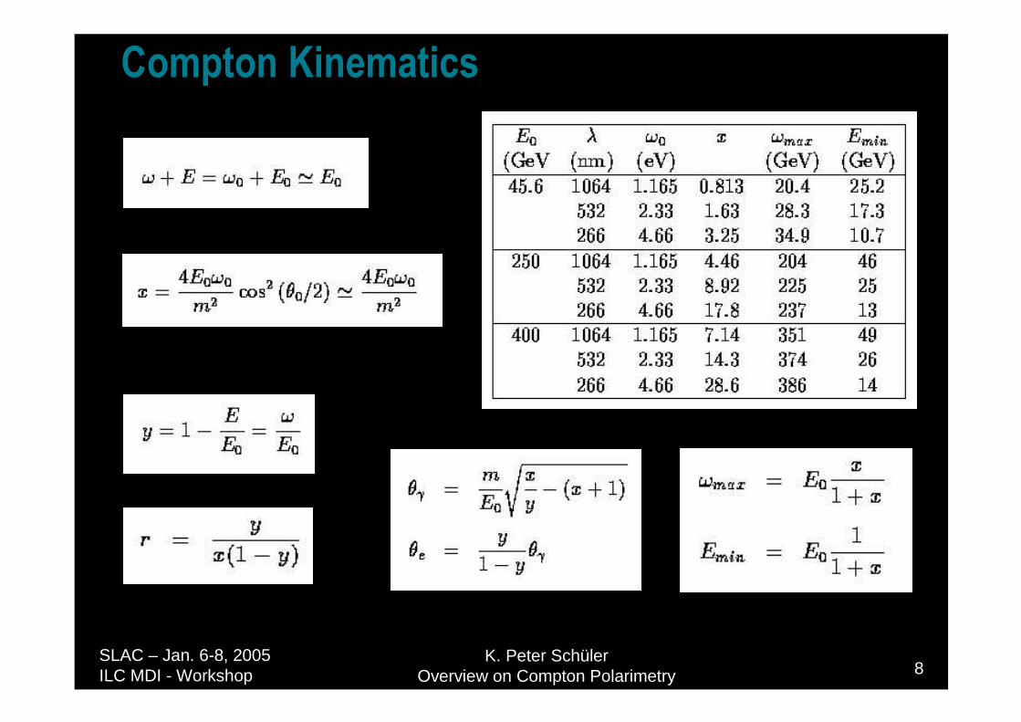
Eo = 45.6 GeVωo = 4.66 eV (UV)
Eo = 250 GeVωo = 2.33 eV (green)
Eo = 400 GeVωo = 1.165 eV (IR)
may need to adjust wavelength of laser to obtain acceptable coverage of Compton edge region for all beam energies
K. Peter SchülerOverview on Compton Polarimetry 11
SLAC – Jan. 6-8, 2005 ILC MDI - Workshop
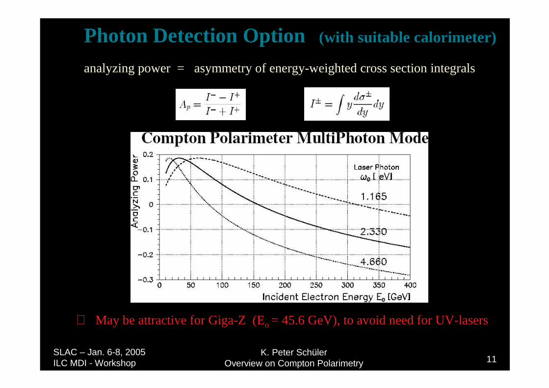
Photon Detection Option (with suitable calorimeter)
analyzing power = asymmetry of energy-weighted cross section integrals
⇒ May be attractive for Giga-Z (Eo = 45.6 GeV), to avoid need for UV-lasers
K. Peter SchülerOverview on Compton Polarimetry 12
SLAC – Jan. 6-8, 2005 ILC MDI - Workshop
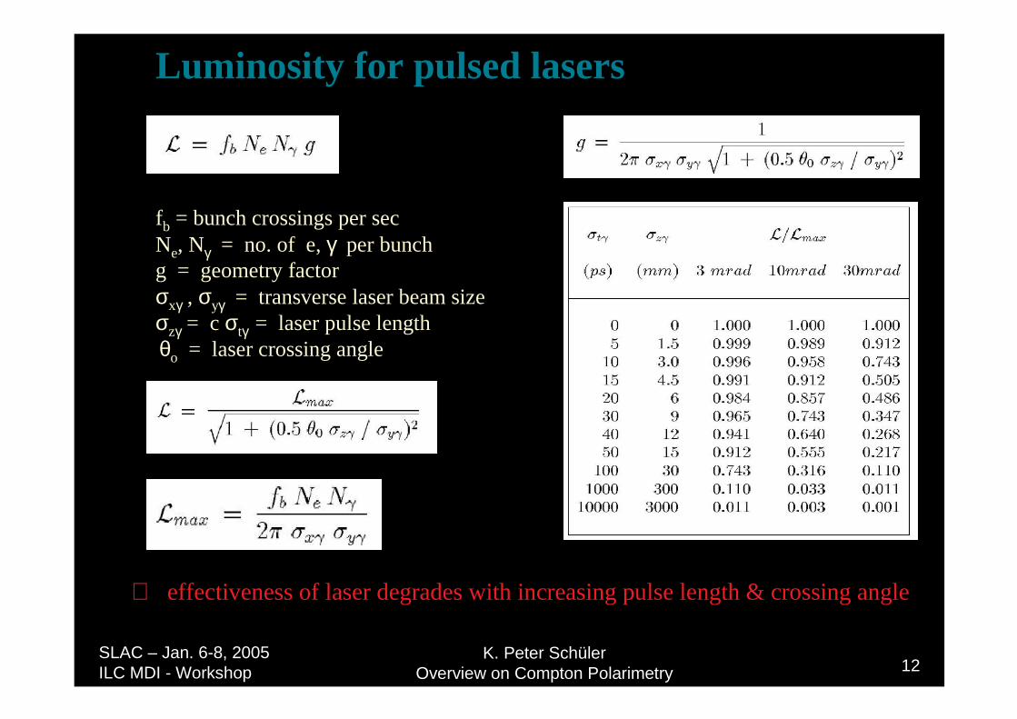
Luminosity for pulsed lasers
fb = bunch crossings per secNe, Nγ = no. of e, γ per bunchg = geometry factorσxγ , σyγ = transverse laser beam sizeσzγ = c σtγ = laser pulse lengthθo = laser crossing angle
⇒ effectiveness of laser degrades with increasing pulse length & crossing angle
K. Peter SchülerOverview on Compton Polarimetry 13
SLAC – Jan. 6-8, 2005 ILC MDI - Workshop
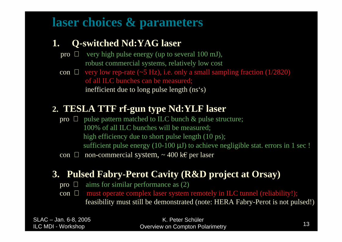
laser choices & parameters
1. Q-switched Nd:YAG laserpro ⇒ very high pulse energy (up to several 100 mJ),
robust commercial systems, relatively low costcon ⇒ very low rep-rate (~5 Hz), i.e. only a small sampling fraction (1/2820)
of all ILC bunches can be measured;inefficient due to long pulse length (ns‘s)
2. TESLA TTF rf-gun type Nd:YLF laserpro ⇒ pulse pattern matched to ILC bunch & pulse structure;
100% of all ILC bunches will be measured;high efficiency due to short pulse length (10 ps);sufficient pulse energy (10-100 µJ) to achieve negligible stat. errors in 1 sec !
con ⇒ non-commercial system, ~ 400 k per laser
3. Pulsed Fabry-Perot Cavity (R&D project at Orsay)pro ⇒ aims for similar performance as (2)con ⇒ must operate complex laser system remotely in ILC tunnel (reliability!);
feasibility must still be demonstrated (note: HERA Fabry-Perot is not pulsed!)
K. Peter SchülerOverview on Compton Polarimetry 14
SLAC – Jan. 6-8, 2005 ILC MDI - Workshop
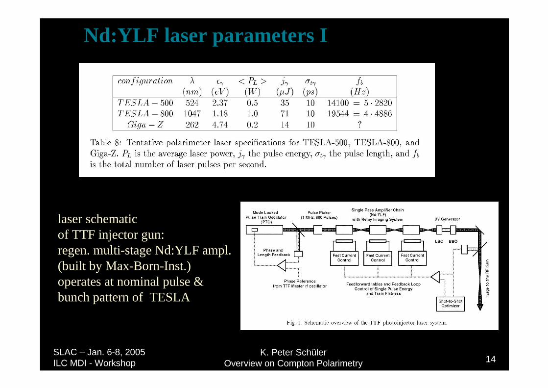
laser schematic of TTF injector gun:regen. multi-stage Nd:YLF ampl.(built by Max-Born-Inst.)operates at nominal pulse &bunch pattern of TESLA
Nd:YLF laser parameters I
K. Peter SchülerOverview on Compton Polarimetry 15
SLAC – Jan. 6-8, 2005 ILC MDI - Workshop
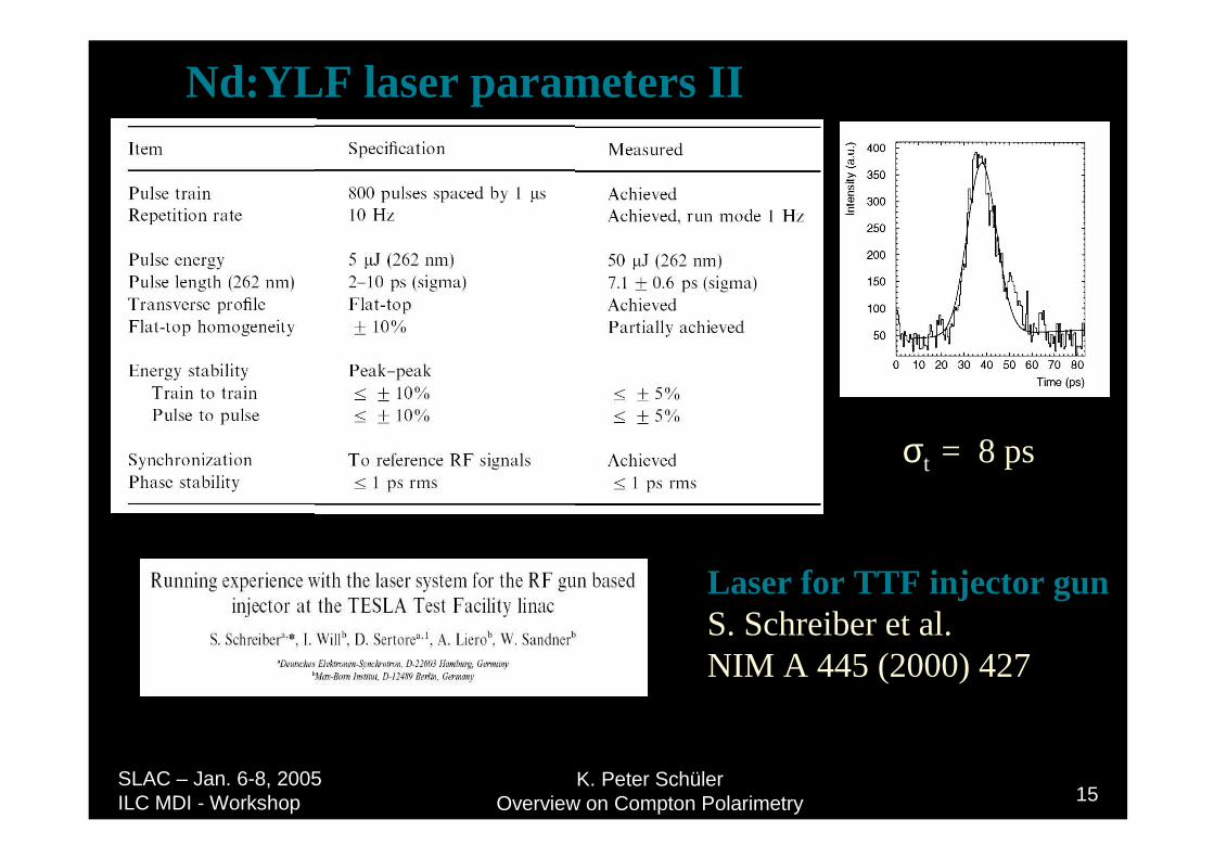
Nd:YLF laser parameters II
Laser for TTF injector gunS. Schreiber et al.NIM A 445 (2000) 427
σt = 8 ps
K. Peter SchülerOverview on Compton Polarimetry 16
SLAC – Jan. 6-8, 2005 ILC MDI - Workshop
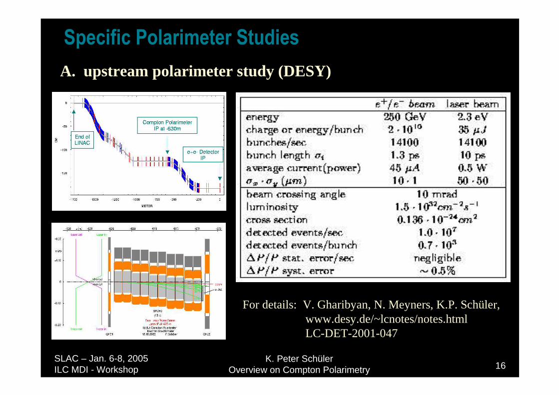
6SHFLILF�3RODULPHWHU�6WXGLHVA. upstream polarimeter study (DESY)
For details: V. Gharibyan, N. Meyners, K.P. Schüler,www.desy.de/~lcnotes/notes.htmlLC-DET-2001-047

K. Peter SchülerOverview on Compton Polarimetry 17
SLAC – Jan. 6-8, 2005 ILC MDI - Workshop
6SHFLILF�3RODULPHWHU�6WXGLHVB. downstream polarimeter study (SLAC)
for details: M. Woods and K.C. Moffeit,SLAC-PUB-10669, Aug. 2004,and K.C. Moffeit, this workshop
low-energy Compton electrons will bewell-separated from disrupted beam(for 20 mrad linac crossing angle!)
4-magnet chicane with 2nd beam focusand laser crossing at center of chicane
Laser: 532 nm, 100 mJ, 2 ns FWHM,5 Hz, 100 µm spot size, 11.5 mrad beam crossing angle
K. Peter SchülerOverview on Compton Polarimetry 18
SLAC – Jan. 6-8, 2005 ILC MDI - Workshop
6XPPDU\Upstream polarimeter study (DESY):
u assumes suitable magnetic bend (~ 1 mrad) withdog-leg or chicane geometry
u custom-built laser system (similar to existing facility at DESY)with pulse pattern matched to ILC bunch structure (14 100 per sec)
u very fast, robust facility, precision of ∆P/P ~ 0.25%
Downstream polarimeter study (SLAC):u Assumes 20 mrad linac crossing angle
with suitable magnetic chicane u commercial laser system (similar to SLD polarimeter laser)
which samples fraction of ILC bunches (5 per sec)u Low-energy Compton electrons are well-separated from
disrupted beam background, precision of ∆P/P ~ 0.25%

K. Peter SchülerOverview on Compton Polarimetry 19
SLAC – Jan. 6-8, 2005 ILC MDI - Workshop
GRZQVWUHDP��H[WUDFWLRQ OLQH��VWXGLHV IRU�7(6/$/DVHU�%HDP�7RSRORJ\ TESLA beam extraction scheme
laser beam crossing inside the big detector! place Compton electron detector at z = 65 m(behind MSEP magnet)
additional material:
K. Peter SchülerOverview on Compton Polarimetry 20
SLAC – Jan. 6-8, 2005 ILC MDI - Workshop
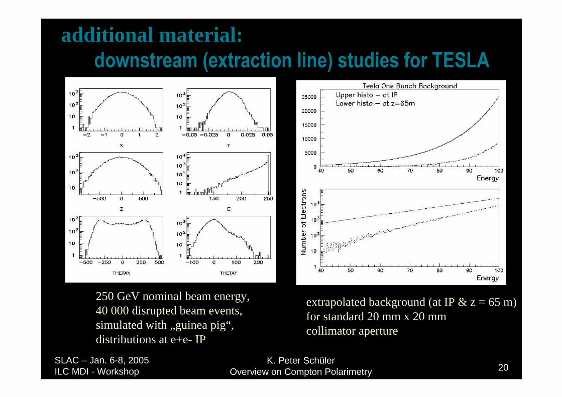
GRZQVWUHDP��H[WUDFWLRQ OLQH��VWXGLHV IRU�7(6/$
250 GeV nominal beam energy,40 000 disrupted beam events,simulated with „guinea pig“,distributions at e+e- IP
extrapolated background (at IP & z = 65 m)for standard 20 mm x 20 mm collimator aperture
additional material:
K. Peter SchülerOverview on Compton Polarimetry 21
SLAC – Jan. 6-8, 2005 ILC MDI - Workshop
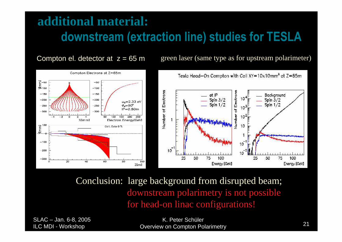
GRZQVWUHDP��H[WUDFWLRQ OLQH��VWXGLHV IRU�7(6/$�Compton el. detector at z = 65 m green laser (same type as for upstream polarimeter)
Conclusion: large background from disrupted beam;downstream polarimetry is not possible for head-on linac configurations!
additional material: