overview of hazardous waste incineration technology · assure complete oxidation of the waste...
TRANSCRIPT
OVERVIEW OF HAZARDOUS WASTE
INCINERATION TECHNOLOGY
H. E. BARNER J. S. CHARTIER J. A. VETTER Lurgi Corporation
River Edge, New Jersey
ABSTRACT
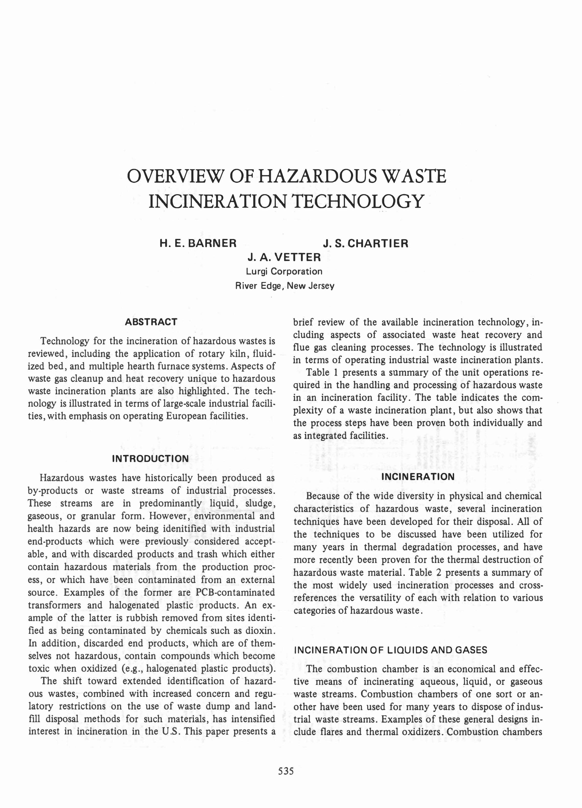
Technology for the incineration of hazardous wastes is reviewed, including the application of rotary kiln, fluidized bed, and multiple hearth furnace systems. Aspects of waste gas cleanup and heat recovery unique to hazardous waste incineration plants are also highlighted. The technology is illustrated in terms of large-scale industrial facilities, with emphasis on operating European facilities.
INTRODUCTION
Hazardous wastes have historically been produced as by-products or waste streams of industrial processes. These streams are in predominantly liquid, sludge, gaseous, or granular form. However, environmental and health hazards are now being idenitified with industrial end-products which were previously considered acceptable, and with discarded products and trash which either contain hazardous materials from the production process, or which have been contaminated from an external source. Examples of the former are PCB-contaminated transformers and halogenated plastic products. An example of the latter is rubbish removed from sites identified as being contaminated by chemicals such as dioxin. In addition, discarded end products, which are of themselves not hazardous, contain compounds which become toxic when oxidized (e.g., halogenated plastic products).
The shift toward extended identification of hazardous wastes, combined with increased concern and regulatory restrictions on the use of waste dump and landfill disposal methods for such materials, has intensified interest in incineration in the U.S. This paper presents a
brief review of the available incineration technology, including aspects of associated waste heat recovery and flue gas cleaning processes. The technology is illustrated in terms of operating industrial waste incineration plants.
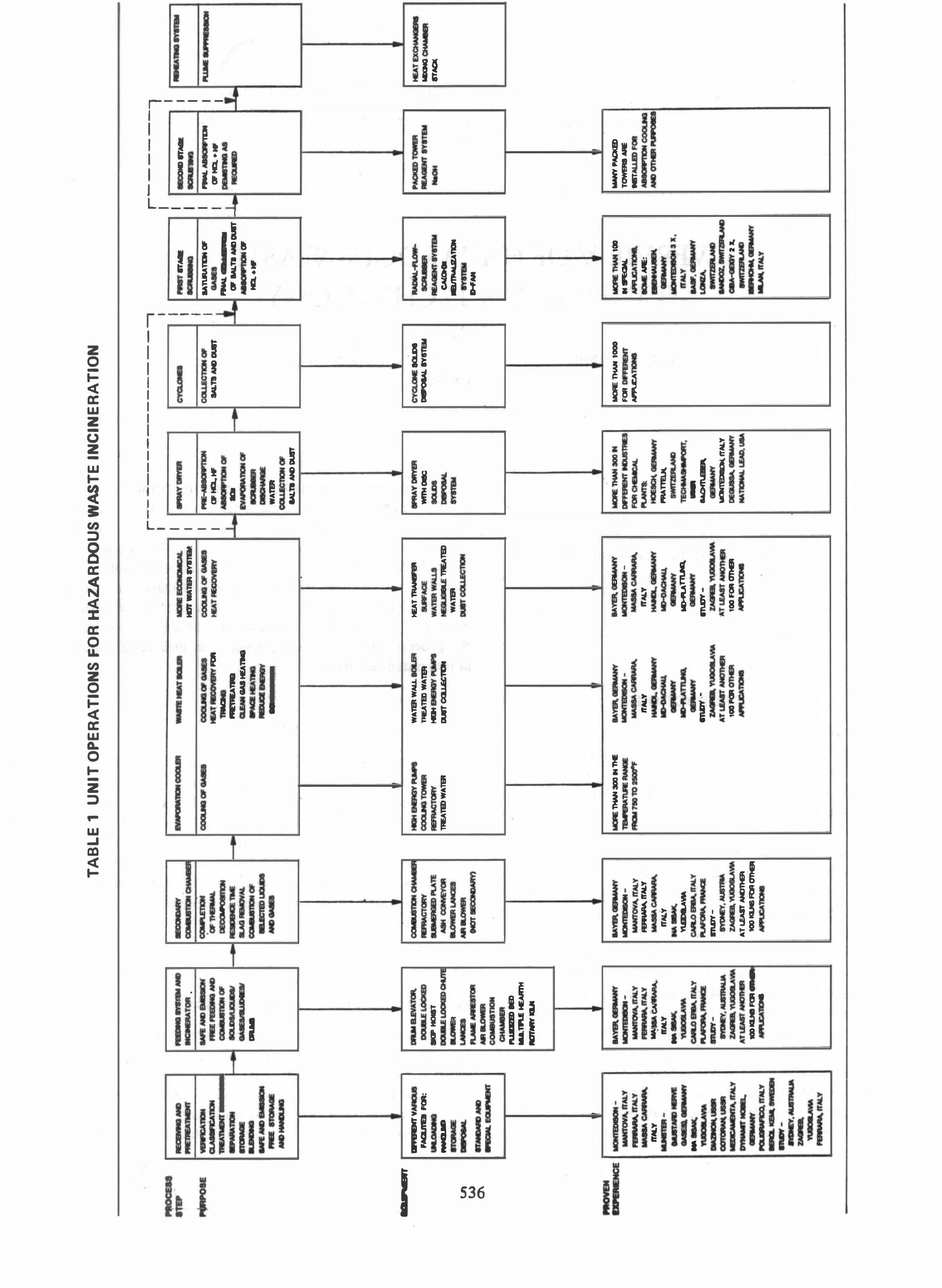
Table 1 presents a summary of the unit operations required in the handling and processing of hazardous waste in an incineration facility. The table indicates the complexity of a waste incineration plant, but also shows that the process steps have been proven both individually and as integrated facilities.
INCIN ERATION
Because of the wide diversity in physical and chemical characteristics of hazardous waste, several incineration techniques have been developed for their disposal. All of the techniques to be discussed have been utilized for many years in thermal degradation processes, and have more recently been proven for the thermal destruction of hazardous waste material. Table 2 presents a summary of the most widely used incineration processes and crossreferences the versatility of each with relation to various categories of hazardous waste.
535
INCINERATION OF LIQUIDS AND GASES
The combustion chamber is an economical and effective means of incinerating aqueous, liquid, or gaseous waste streams. Combustion chambers of one sort or another have been used for many years to dispose of industrial waste streams. Examples of these general designs include flares and thermal oxidizers. Combustion chambers
�
VI
W
0\
• , thEW
-i'LU
-.
¥I
".US A
I'DI
I'!I •
;A
1'ICIC
Ii A
n M
N'nr
__
-
OIl
......
M
II
- MII I W
D •
•
GUcarry ..
.. ,.8
FACIJI'IES PQR
: .-
ft·
'Q
,WDID
alu
' F
.' m·
u' ,-:-:e
I .,..IS
lieN
...
..... i1
CHA.
rrAL
Y
: C
ZA
'UJ:. II'
ALY
lIP II
' Ql
IIIL·
, _J
,
rrM,
Y
IE
I&
MT
1222-
-,
-•
I
••
\
Gilttn' u
.
n •
•
- "
JIG.
7
o.lf
M.Y
..
. -.-
. _
....
.
., "
-
•
1El'.",*n
,,»
'A'"
.
--
-
'I"
• -
tt".A
: S
Dl\'Ut.
II'AL
Y
•
.ATOR
• UJE
AlDC
W
�
,
."AID
o
n_IDliOl
l ..
.. .,..-
�
•. ..,.
.£ AI
-- !R
H IlrI
Al"CI\.
.. tta.T
-.
......1
1'InI._
�.nr
..... _
.,
•• 2
•
tU .a
,".AME)
..
.. TI'U HEAI
I1H ..
... _ ..
...
IAYI
I\' ",
,..
z a EL
",,", Ii'
M.. Y
W
• Co'
._'
• --M;.
.
M,Y
-'*-
"' ..
.. -
_CMCoCU
Ii'M.
.Y
fl.Jd C
l\. Ii
W •
..
..,.,-.t1Iu.
�
v.I
1CD1CI:e
FORou
u. US
CAn:
:: •
TA
BL
E 1
U
NIT
OP
ER
AT
ION
S F
OR
HA
ZA,R
DOU
S W
AST
E I
NC
INE
RA
TIO
N
an'H.
0'
" •
.,.
o
LEiilH
• OFnE
''IL
ce.
caliON
�
'.
. 'I
IoIE
MiG"
.
00' •
• '01
I=i
iAGIClH. •
n
-PlATE
MH
OCI NF:r
OR
.Cnaw
2.
...•
l1'li. ;.
�
1AY!R,
' 'Mil"
:saa-AIr
ALY
w
'C/
•
• ,
.
\"_-'i.
�
rrM.
Y
-.-
_lAo
"'QWA
'M
QI"O
sa",Ir
Al.Y
� 01
4 ""
" •
....,.,-
AT ',.
..-rAMOna
1CXJ ICIPB
PCROI
IE.
B'lb 0
",..0.
.... ,
COCIMlOF
GA
loDt B
S iGi
't'"
•
COOl tG
TCUUW
IE iJ.C
IQh'
nEA
l&) W
A'TBt
w: L
lMAN 30
0 NnE
:
,
a'cHEAT
" :
"='Cn_OF
N •
tEA
TS lQueCi
POI'I
Ii
•
£2EhU�
Q !'"
8M tEA
lWIa
2 •
...
a ..
QC
S' 'iM
WAlIA
.AL
L ... L
1'REA
TID W
ATBt
I«IH aEL'I'
,,�
•
..., ••
�CXlI"·li
ON
lAYER,
' MI
....
MONjB
II CI
II-..
.. 1 5"
Ch a
A"t:t".
trlrL
Y
--
.. �
-
'''1ft'
....,., ..
ZI"
,. PCIiI
0 Ii
lUI
US I'!AIK
.
_A1
�
ICJT
WAlBt
e.ela'
ca',.OI
U •
HEA
T:
thU"
tEATTIW&a:
•
SACE.
W
A'fERW
.... '.
'EC'
F
IIUT'B)
W
ATEIt
awr en
' RID
lAYER.
' "'N'
MON
iS li
ON ..
. It'
"
CJJ •
UN.
rrM.
Y
HA-a.'
'Oft'
.., PLA
TTUIII.
GE I'
Nft'
.",.".
... '1" '"
A 'M
%Aii
100
fQR Ol
la.
U 2
1'!4i1
•
r-
--
--
--
--
--
--
--
.
I I I I I
• Sa
y ..
.. "
ilE
,'IT a
I ....
ClI'HCL.
"
, 7
SIDCW:
-
EVa
a ",
,1'ICIC OF
ICI'
,
f a
...
WATI
It CO
' ••
ICHOI
I .,;1'8
AID OIJIT
• : LA
Y DRTS.
Wl
lHcec
.....
. 18
-
m �
-
M E
1lWt30
0N
LW'.UENf MJl
B j l
Ea
FORa
ee
....
...,..,.
..... 10\
C ''
''1i' -
nnH.
on EJlU
ND
.- �
. .."
" �
rrAL
Y
-
",to U
•
"'US AM)
DUI'f
cya
mE
1(1"
ca �
..,1ItBI
Mel E
THAN 1
000
FOR
DE
: C
EJT
APPt.JCA TIC
I.
I I I I I
, ••
, ar-
,..
--'"
IA
1\JRATUI
OF
Oa •
PlW.
CO'fC·'1M
r--
--
--l
I
I I
., ..
... _
I
I ..
.. II
I I
AlAI. 'I
I :
a '1M
I
I OF
HCL·"
I
rn
hll M
OF
IALD
NDawr
I '_I $
• ..
., • lAM
OF
HCL·"
MOW.: "
nee
....
'£" If
..ala·
CAl"..
....-aATI
III -
--
_.
.T
.'"
_
NO
.. a:
1lWt 1
00
.. -
40 C
An: ..
..
. MilE
:
."
1M.,"
qf
f
UlDP.les:l'
LVI)
0"'''-lot
Z X.
I"'p
UfCt
lie" c
"'R'
.-""
rrAL
Y
WIn' "
ACMe.
TQllhSU ARE
..,.
... 'm
'CIR
d IlEA
.,.. ...
8'
'
....
e·
"
•
�T
EXc:
:w..." •
..
.. QtuIE.
... ..
...
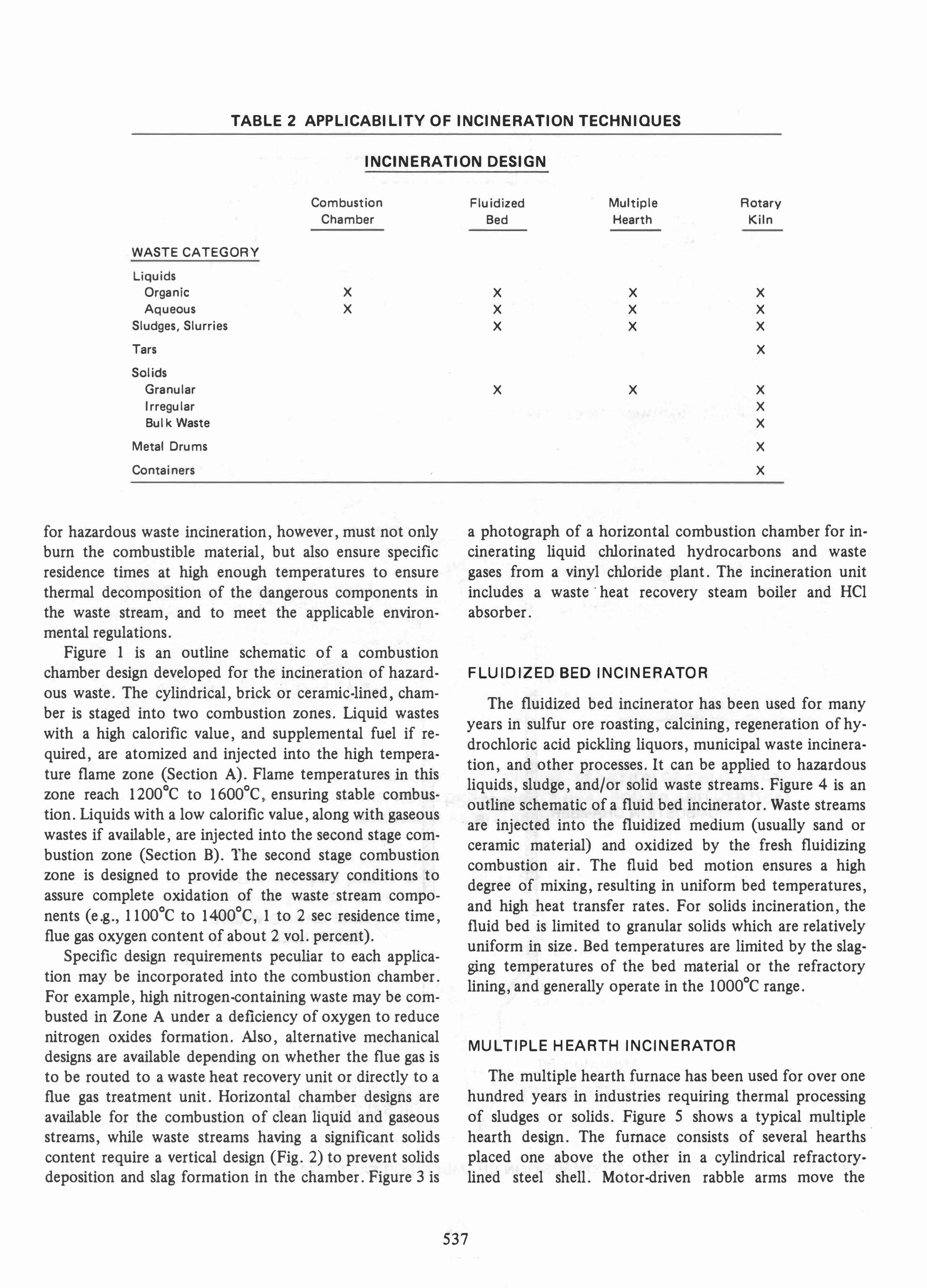
TABLE 2 APPLICABILITY O F INCINERATION TECHNIQUES
INCINERATION DESIGN
WASTE CATEGORY
Liquids
Organic
Aqueous
Sludges, Slurries
Tars
Solids
Granular
I rregu lar
Bul k Waste
Metal Drums
Containers
Combustion
Chamber
X X
for hazardous waste incineration, however, must not only burn the combustible material, but also ensure specific residence times at high enough temperatures to ensure thermal decomposition of the dangerous components in the waste stream, and to meet the applicable environmental regulations.
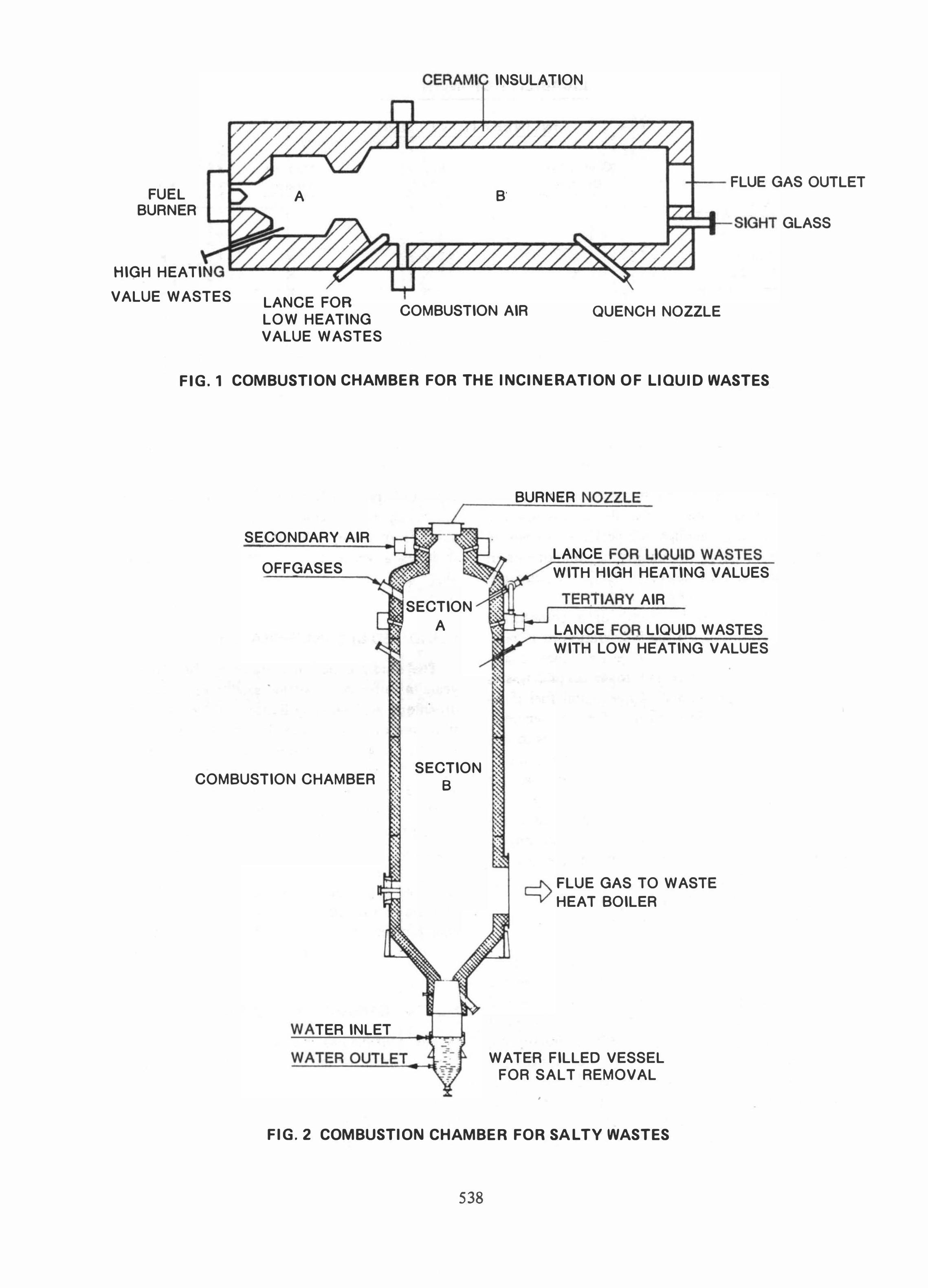
Figure 1 is an outline schematic of a combustion chamber design developed for the incineration of hazardous waste. The cylindrical, brick or ceramic-lined, chamber is staged into two combustion zones. Liquid wastes with a high calorific value, and supplemental fuel if required, are atomized and injected into the high temperature flame zone (Section A). Flame temperatures in this zone reach 1 200°C to 1 600°C,. ensuring stable combustion. Liquids with a low calorific value, along with gaseous wastes if available, are injected into the second stage combustion zone (Section B). The second stage combustion zone is designed to provide the necessary conditions to assure complete oxidation of the waste stream components (e.g., 1 1 00°C to 1 400°C, 1 to 2 sec residence time, flue gas oxygen content of about 2 vol. percent).
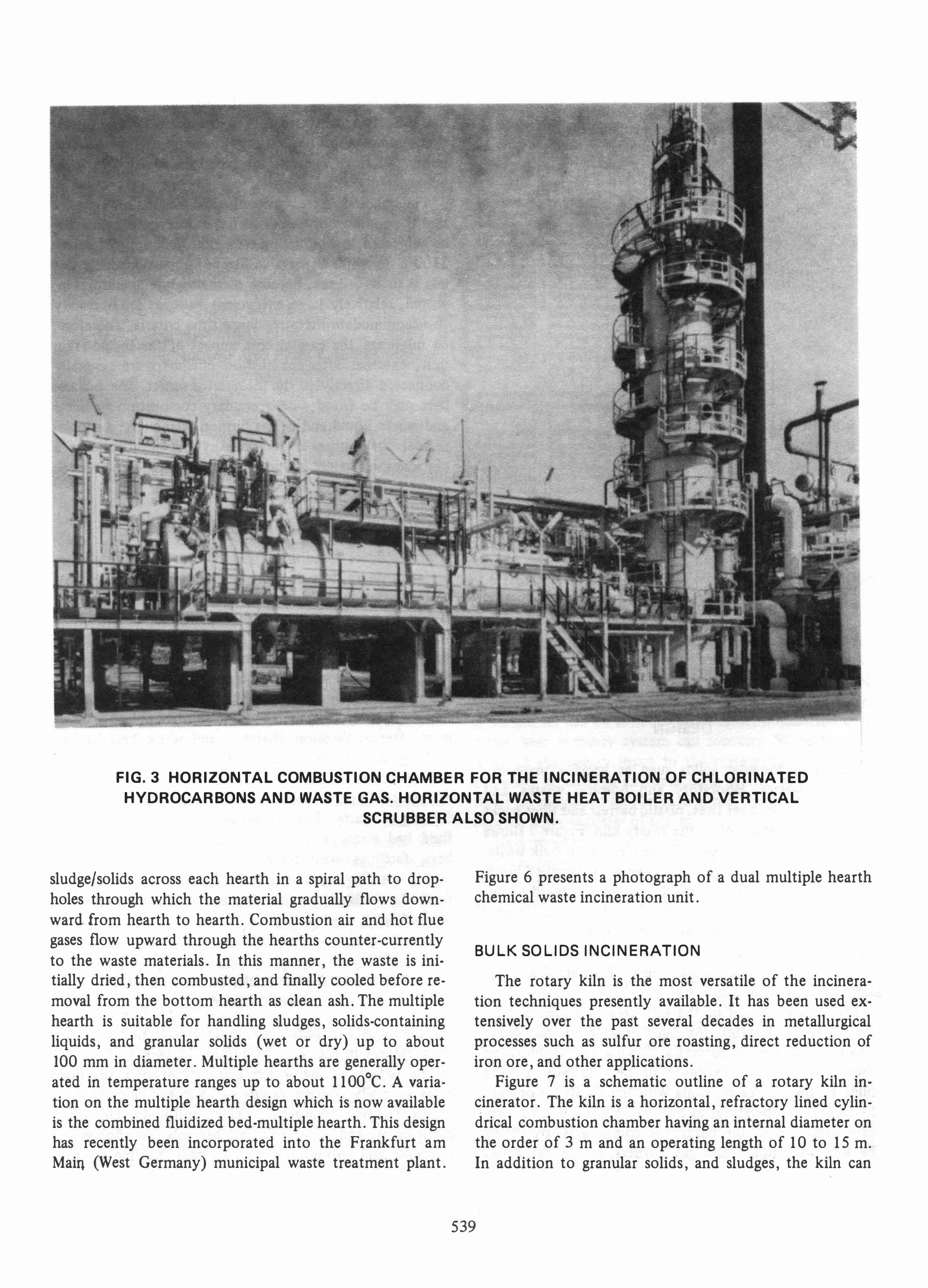
Specific design requirements peculiar to each application may be incorporated into the combustion chamber. For example, high nitrogen-containing waste may be combusted in Zone A under a deficiency of oxygen to reduce nitrogen oxides formation. Also, alternative mechanical designs are available depending on whether the flue gas is to be routed to a waste heat recovery unit or directly to a flue gas treatment unit. Horizontal chamber designs are available for the combustion of clean liqUid and gaseous streams, while waste streams having a significant solids content require a vertical design (Fig. 2) to prevent solids deposition and slag formation In the chamber. Figure 3 is
Flu idized
Bed
X X X
X
Multiple
Hearth
X X X
X
Rotary
Kiln
X X X
X
X X X
X
X
a photograph of a horizontal combustion chamber for incinerating liquid chlorinated hydrocarbons and waste gases from a vinyl chloride plant. The incineration unit includes a waste' heat recovery steam boiler and HCl absorber.
F LUIDIZED BED INCINERATOR
The fluidized bed incinerator has been used for many years in sulfur ore roasting, calcining, regeneration of hydrochloric acid pickling liquors, municipal waste incineration, and other processes. It can be applied to hazardous liquids, sludge, and/or solid waste streams. Figure 4 is an outline schematic of a fluid bed incinerator. Waste streams are injected into the fluidized medium (usually sand or ceramic material) and oxidized by the fresh fluidizing combustion air. The fluid bed motion ensures a high degree of mixing, resulting in uniform bed temperatures, and high heat transfer rates. For solids incineration, the fluid bed is limited to granular solids which are relatively uniform in size. Bed temperatures are limited by the slagging temperatures of the bed material or the refractory lining, and generally operate in the 1 000°C range.
MU LTIP LE HEARTH INCINERATOR
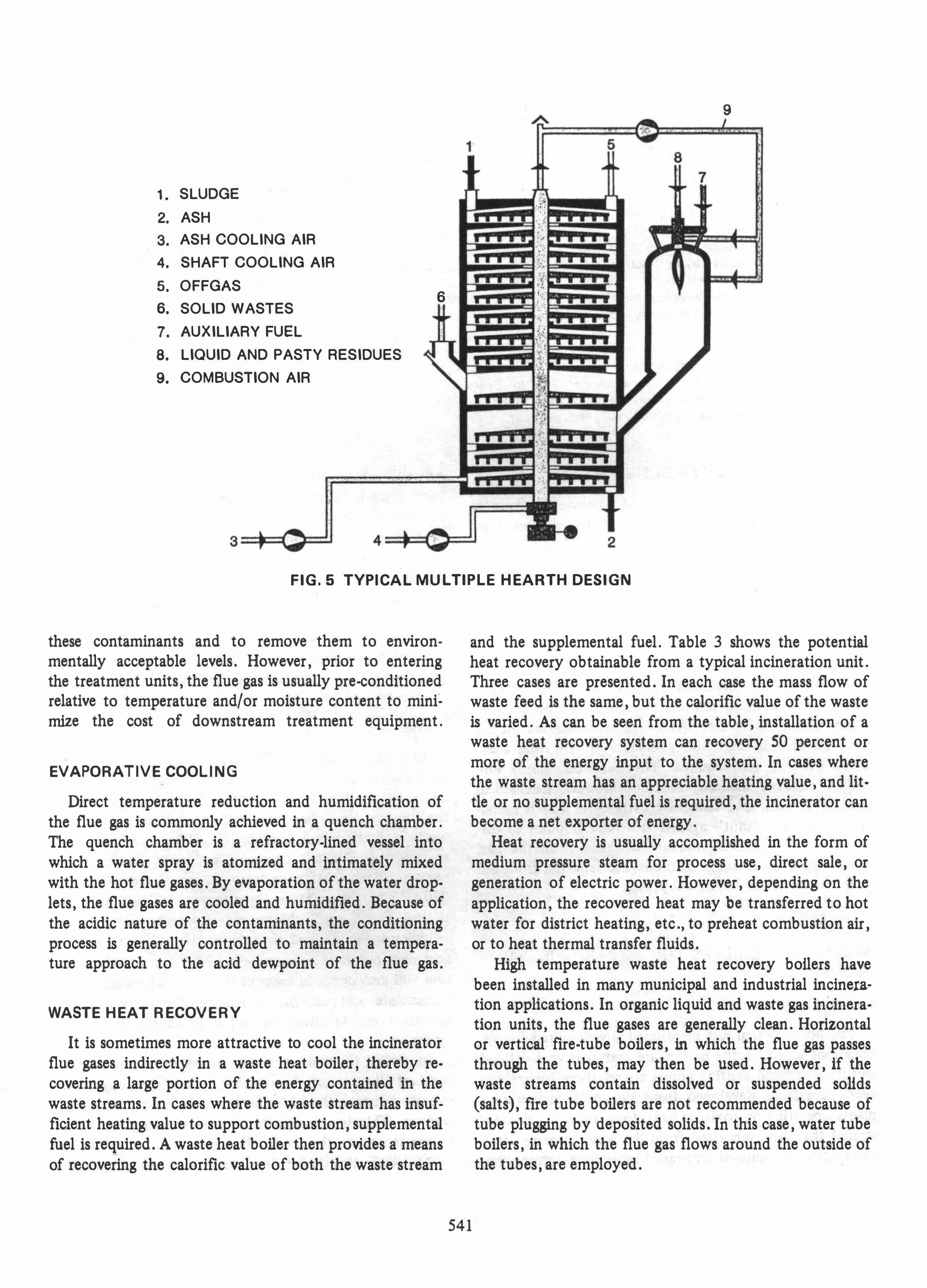
The multiple hearth furnace has been used for over one hundred years in industries requiring thermal processing of sludges or solids. Figure 5 shows a typical multiple hearth deSign. The furnace consists of several hearths placed one above the other in a cylindrical refractorylined steel shell. Motor-driven rabble arms move the
537
FUEL BURNER
HIGH HEATI
VALUE WASTES
A
LANGE FOR LOW HEATING V ALUE WASTES
CER,I INSULATION
+-- FLUE GAS OUTLET B'
-SIGHT GLASS
COMBUSTION AIR QUENCH NOZZLE
FIG.1 COMBUSTION CHAMBER FOR THE INCINERATION O F LIQUID WASTES
SECONDARY AIR
OFFGASES
COMBUSTION CHAMBER
TER INLET
, SECTION
A
SECTION B
BURNER
LANCE r::r WITH HIGH HEATING VALUES
AIR
LANCE LIQUID WASTES
WITH LOW HEATING VALUES
..--J'.- FLUE GAS TO WASTE
'---v' HEAT BOILER
WATER FILLED VESSEL FOR SALT REMOVAL
•
FIG. 2 COMBUSTION CHAMBER FOR SAL TV WASTES
538
· t
FIG.3 HORIZONTAL COMBUSTION CHAMBER FOR THE INCINERATION O F CHLORINATED
HYDROCARBONS AND WASTE GAS. HORIZONTAL WASTE HEAT BOILER AND VERTICAL
SCRUBBER ALSO SHOWN.
sludge/solids across each hearth in a spiral path to dropholes through which the material gradually flows downward from hearth to hearth. Combustion air and hot flue gases flow upward through the hearths counter-currently to the waste materials. In this manner, the waste is initially dried, then combusted, and fmally cooled before removal from the bottom hearth as clean ash. The multiple hearth is suitable for handling sludges, solids-containing liquids, and granular solids (wet or dry) up to about 100 mm in diameter. Multiple hearths are generally operated in temperature ranges up to about 1 1 OO°C. A variation on the multiple hearth design which is now available is the combined fluidized bed-multiple hearth. This design has recently been incorporated into the Frankfurt am Main (West Germany) municipal waste treatment plant.
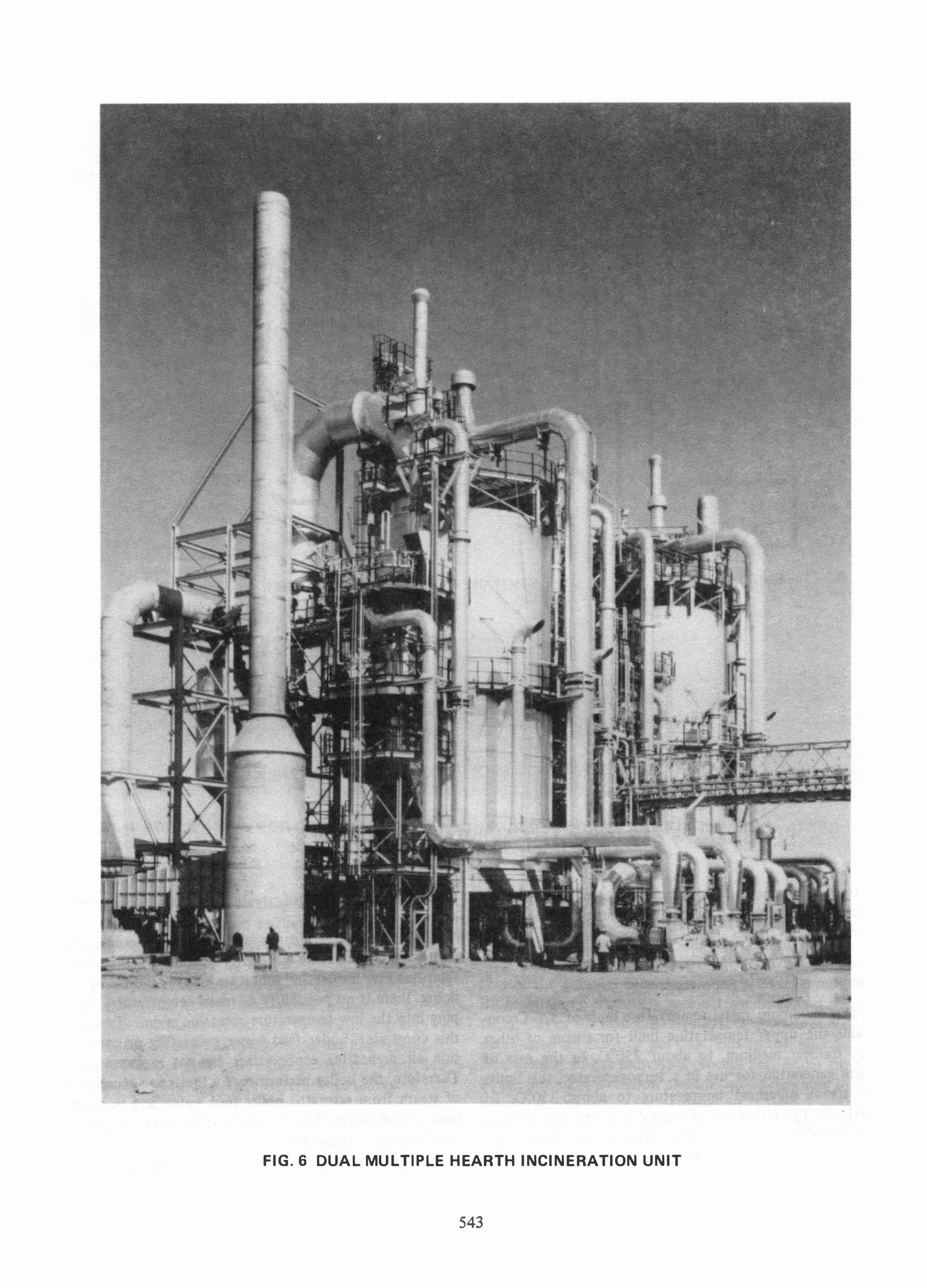
Figure 6 presents a photograph of a dual multiple hearth chemical waste incineration unit.
BULK SOLIDS INCINERATION
The rotary kiln is the most versatile of the incineration techniques presently available. It has been used extensively over the past several decades in metallurgical processes such as sulfur ore roasting, direct reduction of iron ore, and other applications.
Figure 7 is a schematic outline of a rotary kiln incinerator. The kiln is a horizontal, refractory lined cylindrical combustion chamber having an internal diameter on the order of 3 m and an operating length of 1 0 to 1 5 m. In addition to granular solids, and sludges, the kiln can
539

SCRUBBE EFFLUENT
MAKE-UP
ADDITIONAL FUEL
WASTE GAS
ER WATER SUPPLY
SECONDARY AIR
W
FUEL
AIR
FIG.4 FLUID BED INCINERATOR CONCEPTUAL
DESIGN
handle large irregular solids such as packmg materials, municipal wastes, laboratory and hospital wastes, and general refuse. Rubber tires, plastic barrels and fiber packs can also be disposed of in the rotary kiln. Figure 7 shows the hopper feed system used for miscellaneous bulk waste. The bulk solids are fed to the hopper by a clamshell hoist. Also shown in the figure are the lances for liquid waste, sludge waste, and supplemental fuel firing. An elevator system with a ram feeding device can be provided and the kiln designed to accept 50 gal metal drums filled with organic waste. In this case the drums are discharged as a slag along with the combustion ash.
The rotary motion of the kiln creates a tumbling action, thereby assuring thorough mixing of the waste streams with the co-currently flowing hot combustion gases. The constant exposure of new surfaces of the solids to the hot gases, along with the ability to operate the kiln at temperatures as high as 1600°C, assures complete oxidation of the hazardous compounds. By fitting the kiln with liquid and gas burners, several categories
540
of hazardous waste may be treated simultaneously. In the U.S., two commercial PCB incinerators are in operation, and a third is waiting EPA approval of its test burns. All three facilities are based on rotary kiln technology.
Federal and state environmental regulations require that the combustion gases of a hazardous waste incinerator be subjected to a minimum temperature of approximately 1100°C to 1400°C for a residence time of generally not less than 1 to 2 sec. Because of the high temperatures involved, relatively large equipment volumes are necessary to accommodate these residence time criteria. Therefore, to minimize the capital cost impact of the incineration unit, external after-combustion chambers are generally connected directly to the incinerator outlet. These chambers mily be fitted with secondary combustion air inlets and waste liquid and/or gas burners. Generally, a supplemental fuel burner is required by the authorities as a precauation against reduction of the temperature level.
INTEGRATED INCINERATION FACILITIES
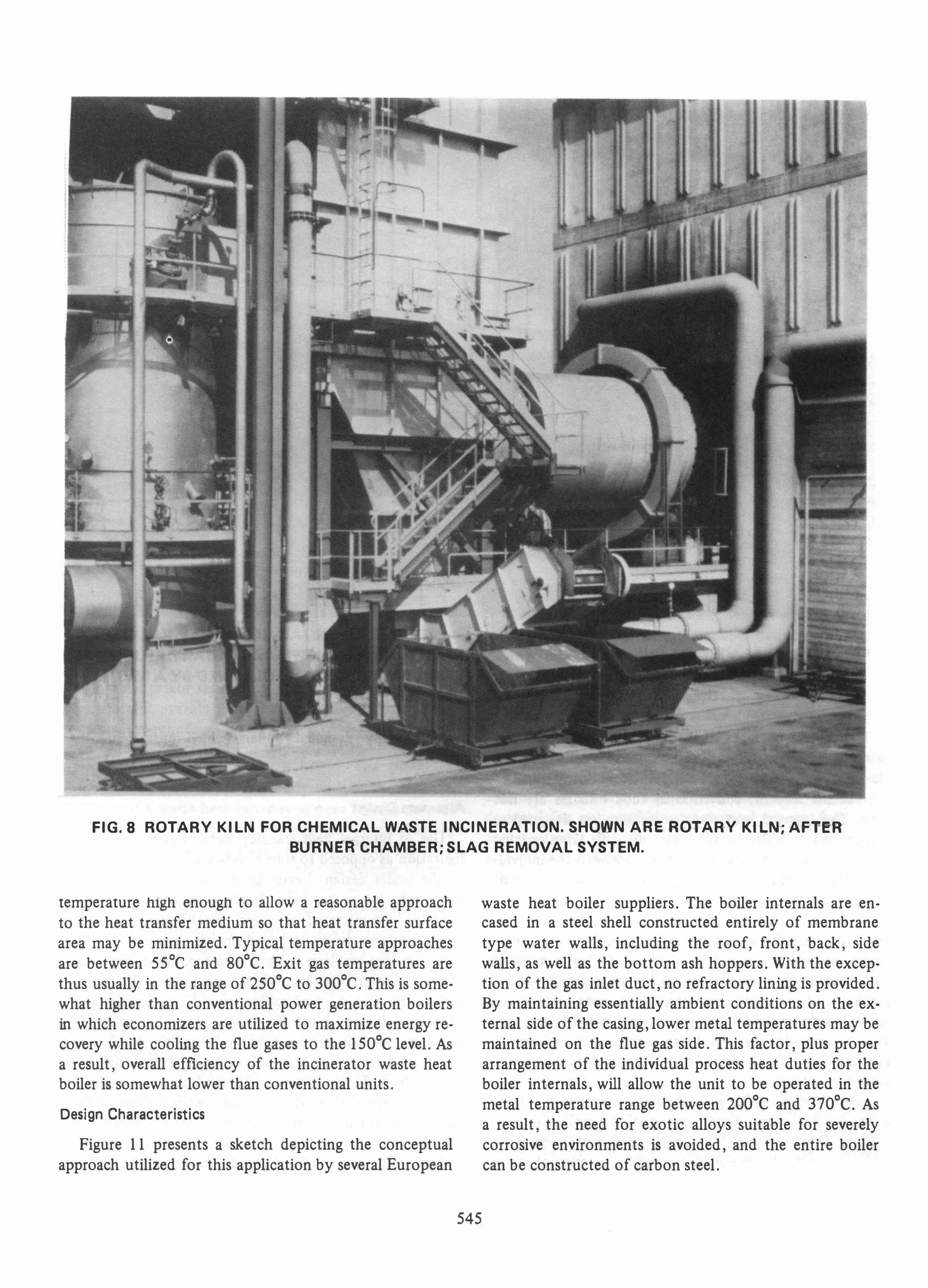
In facilities handling large volumes of varying categories of waste, two or more incineration techniques may be integrated into a single unit. Figures 8 and 9 are photographs of an incineration unit for disposal of hazardous waste in an Italian chemical plant. The rotary kiln is designed to accept bulk solids as well as 50-gal metal drums filled with liquid waste. A liquids combustion chamber is incorporated into this unit, with the flue gases from both the combustion chamber and the kiln routed to a common after-combustion chamber and waste heat boiler.
Lurgi has presently designed and constructed six rotary kiln-based incineration facilities for European chemical plants. Capacities of the kilns range from 0.3 t/h to 5.7 t/h of waste. When combined with multiple hearths, fluid bed incinerators, and/or liquid combustion chambers, facilities with incineration capacities up to 17 metric tons/hr have been built. In each case, emissions from the facility have met the applicable environmental regulations.
FLUE GAS CONDITIONING/WASTE HEAT
RECOVERY
Flue gases exit hazardous waste incineration units at temperatures in the range of 1 l 00°C to 1400°C. Because of the nature of the wastes being incinerated, the flue gases generally contain vapors of hydrogen chloride, hydrogen fluoride, phosphoric oxides, sulfur dioxide, solid particulates, and/or organic salt aerosols. Technology is available, and currently in use, to treat the flue gas for
9
1. SLUDGE
2. ASH
3. ASH COOLING AIR
4. SHAFT COOLING AIR
5. OFFGAS 6
6. SOLID WASTES
7. AUXILIARY FUEL
8. LIQUID AND PASTY RESIDUES
9. COMBUSTION AIR
3==C 4= 2
FIG.5 TYPICAL MU L TIPLE HEARTH DESIGN
these contaminants and to remove them to environmentally acceptable levels. However, prior to entering the treatment units, the flue gas is usually pre-conditioned relative to temperature and/or moisture content to mini� rnize the cost of downstream treatment equipment.
,
EVAPORATIVE COOLING
Direct temperature reduction and humidification of the flue gas is commonly achieved in a quench chamber. The quench chamber is a refractory-lined vessel into which a water spray is atomized and intimately mixed with the hot flue gases. By evaporation of the water droplets, the flue gases are cooled and humidified. Because of the acidic nature of the contaminants, the conditioning process is generally controlled to maintain a temperature approach to the acid dewpoint of the flue gas.
WASTE HEAT RECOVERY
It is sometimes more attractive to cool the incinerator flue gases indirectly in a waste heat boiler, thereby recovering a large portion of the energy contained in the waste streams. In cases where the waste stream has insufficient heating value to support combustion, supplemental fuel is required. A waste heat boiler then provides a means of recovering the calorific value of both the waste stream
and the supplemental fuel. Table 3 shows the potential heat recovery obtainable from a typical incineration unit. Three cases are presented. In each case the mass flow of waste feed is the same, but the calorific value of the waste is varied. As can be seen from the table, installation of a waste heat recovery system can recovery SO percent or more of the energy input to the system. In cases where the waste stream has an appreciable heating value, and little or no supplemental fuel is required, the incinerator can become a net exporter of energy.
Heat recovery is usually accomplished in the form of medium pressure steam for process use, direct sale, or generation of electric power. However, depending on the application, the recovered heat may be transferred to hot water for district heating, etc., to preheat combustion air, or to heat thermal transfer fluids.
541
High temperature waste heat recovery bollers have been installed in many municipal and industrial incinej:ation applications. In organic liquid and waste gas incineration units, the flue gases are generally clean. Horizontal or vertical fire-tube boilers, in which the flue gas passes through the tubes, may then be used. However, if the waste streams contain dissolved or suspended soUds (salts), fire tube boilers are not recommended because of tube plugging by deposited solids. In this case, water tube boilers, in which the flue gas flows around the outside of the tubes, are employed.
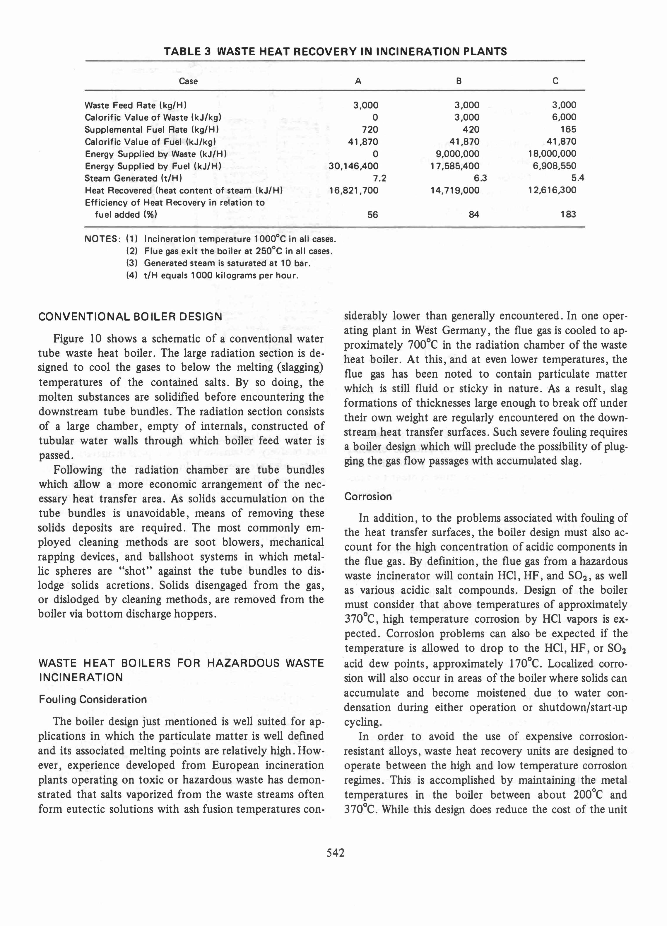
TABLE 3 WASTE HEAT RECOVERY IN INCINERATION PLANTS
Case A B C
Waste Feed Rate (kg/H) 3,000 3,000 3,000 Calorific Value of Waste (kJ/kg) 0 3,000 6,000 Supplemental Fuel Rate (kg/H) 720 420 165 Calorific Value of Fuel (kJ/kg) 41,870 41,870 41,870 Energy Supplied by Waste (kJ/H) 0 9,000,000 18,000,000 Energy Supplied by Fuel (kJ/H) 30,146,400 17,585,400 6,908,550 Steam Generated It/H) 7.2 6.3 5.4
Heat Recovered (heat content of steam (kJ/ H) 16,821,700 14,719,000 12,616,300 Efficiency of Heat Recovery in relation to
fuel added (%)
NOTES: (1) Incineration temperature 1000°C in all cases. (2) Flue gas exit the boiler at 250°C in all cases. (3) Generated steam is saturated at 10 bar. (4) t/H equals 1000 kilograms per hour.
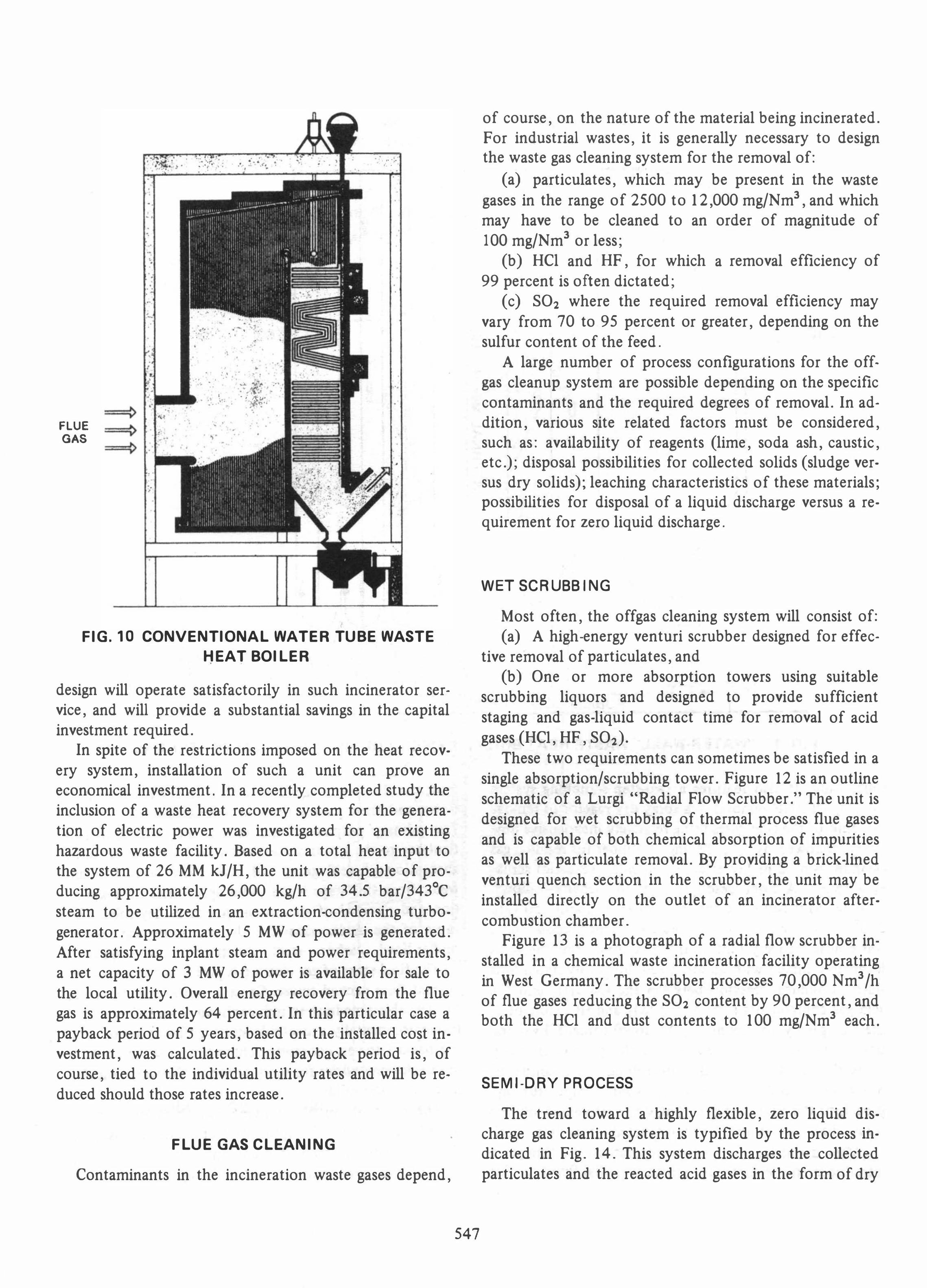
CONVENTIONAL BOILER DESIGN
Figure 10 shows a schematic of a conventional water tube waste heat boiler. The large radiation section is designed to cool the gases to below the melting (slagging) temperatures of the contained salts. By so doing, the molten substances are solidified before encountering the downstream tube bundles. The radiation section consists of a large chamber, empty of internals, constructed of tubular water walls through which boiler feed water is passed.
Following the radiation chamber are tube bundles which allow a more economic arrangement of the necessary heat transfer area. As solids accumulation on the tube bundles is unavoidable, means of removing these solids deposits are required. The most commonly employed cleaning methods are soot blowers, mechanical rapping devices, and ballshoot systems in which metallic spheres are "shot" against the tube bundles to dislodge solids acretions. Solids disengaged from the gas, or dislodged by cleaning methods, are removed from the boiler via bottom discharge hoppers.
WASTE HEAT BOILERS FOR HAZARDOUS WASTE
INCINERATION
Fouling Consideration
The boiler design just mentioned is well suited for applications in which the particulate matter is well defmed and its associated melting points are relatively high. However, experience developed from European incineration plants operating on toxic or hazardous waste has demonstrated that salts vaporized from the waste streams often form eutectic solutions with ash fusion temperatures con-
56 84 183
siderably lower than generally encountered. In one operating plant in West Germany, the flue gas is cooled to approximately 700°C in the radiation chamber of the waste heat boiler. At this, and at even lower temperatures, the flue gas has been noted to contain particulate matter which is still fluid or sticky in nature. As a result, slag formations of thicknesses large enough to break off under their own weight are regularly encountered on the downstream heat transfer surfaces. Such severe fouling requires a boiler design which will preclude the possibility of plugging the gas flow passages with accumulated slag.
Corrosion
In addition, to the problems associated with fouling of the heat transfer surfaces, the boiler design must also account for the high concentration of acidic components in the flue gas. By defmition, the flue gas from a hazardous waste incinerator will contain HCI, HF, and S02, as well as· various acidic salt compounds. Design of the boiler must consider that above temperatures of approximately 370°C, high temperature corrosion by HCI vapors is expected. Corrosion problems can also be expected if the temperature is allowed to drop to the HCI, HF, or S02 acid dew points, approximately 170°C. Localized corrosion will also occur in areas of the boiler where solids can accumulate and become moistened due to water condensation during either operation or shutdown/start-up cycling.
In order to avoid the use of expensive corrosionresistant alloys, waste heat recovery units are designed to operate between the high and low temperature corrosion regimes. This is accomplished by maintaining the metal temperatures in the boiler between about 200°C and 370°C. While this design does reduce the cost of the unit
542
r
•
•
FIG.6 DUAL MULTIPLE HEARTH INCINERATION UNIT
543
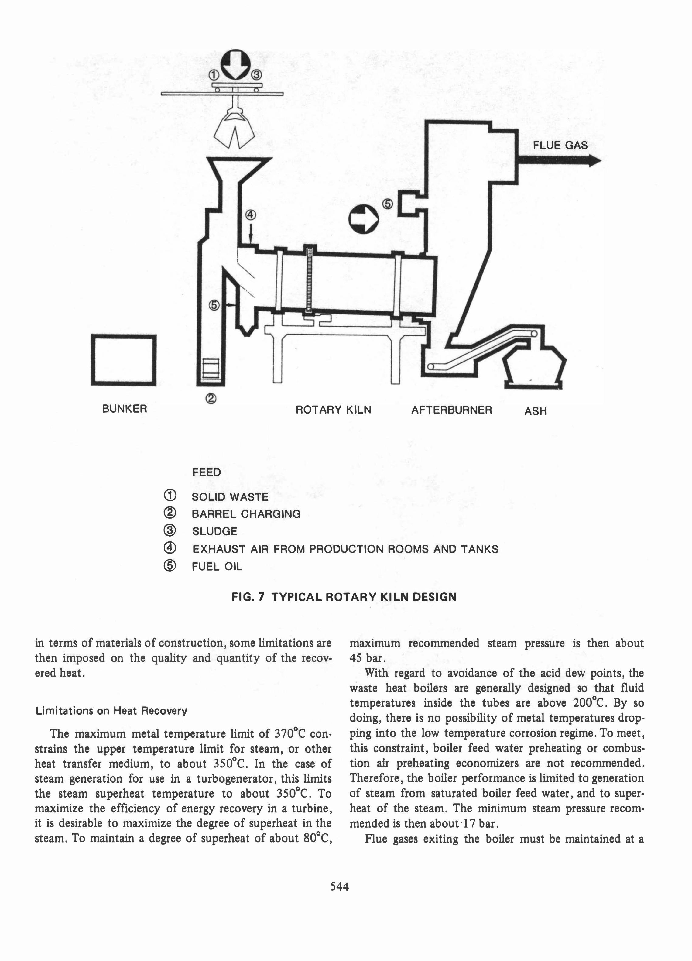
@
FLUE GAS
BUNKER ROTARY KILN AFTERBURNER ASH
FEED
CD SOUD WASTE
® BARREL CHARGING
@ SLUDGE
® EXHAUST AIR FROM PRODUCTION ROOMS AND TANKS
@ FUEL OIL
FIG.7 TYPICAL ROTARY KILN DESIGN
in terms of materials of construction, some limitations are then imposed on the quality and quantity of the recovered heat.
Limitations on Heat Recovery
The maximum metal temperature limit of 370°C constrains the upper temperature limit for steam, or other heat transfer medium, to about 350°C. In the case of steam generation for use in a turbogenerator, this limits the steam superheat temperature to about 350°C. To maximize the efficiency of energy recovery in a turbine, it is desirable to maximize the degree of superheat in the steam. To maintain a degree of superheat of about BO°C,
544
maximum recommended steam pressure is then about 45 bar.
With regard to avoidance of the acid dew points, the waste heat boilers are generally designed so that fluid temperatures inside the tubes are above 200°C. By so doing, there is no possibility of metal temperatures dropping into the low temperature corrosion regime. To meet, this constraint, boiler feed water preheating or combustion air preheating economizers are not recommended. Therefore, the boUer performance is limited to generation of steam from saturated boiler feed water, and to superheat of the steam. The minimum steam pressure recommended is then about '17 bar.
Flue gases exiting the boiler must be maintained at a
•
-'- m •
• . • - -
•
.-
FIG.8 ROTARY KILN FOR CHEMICAL WASTE INCINERATION. SHOWN ARE-ROTARY KilN; AFTE-ft
BURN Elf CHAMBER;SLAG REMOVAL SYSTEM.
temperature high enough to allow a reasonable approach to the heat transfer medium so that heat transfer surface area may be minimized. Typical temperature approaches are between 55°C and 80°C. Exit gas temperatures are thus usually in the range of 250°C to 300°C. This is somewhat higher than conventional power generation boilers in which economizers are utilized to maximize energy recovery while cooling the flue gases to the 150°C level. As a result, overall efficiency of the incinerator waste heat boiler is somewhat lower than conventional units.
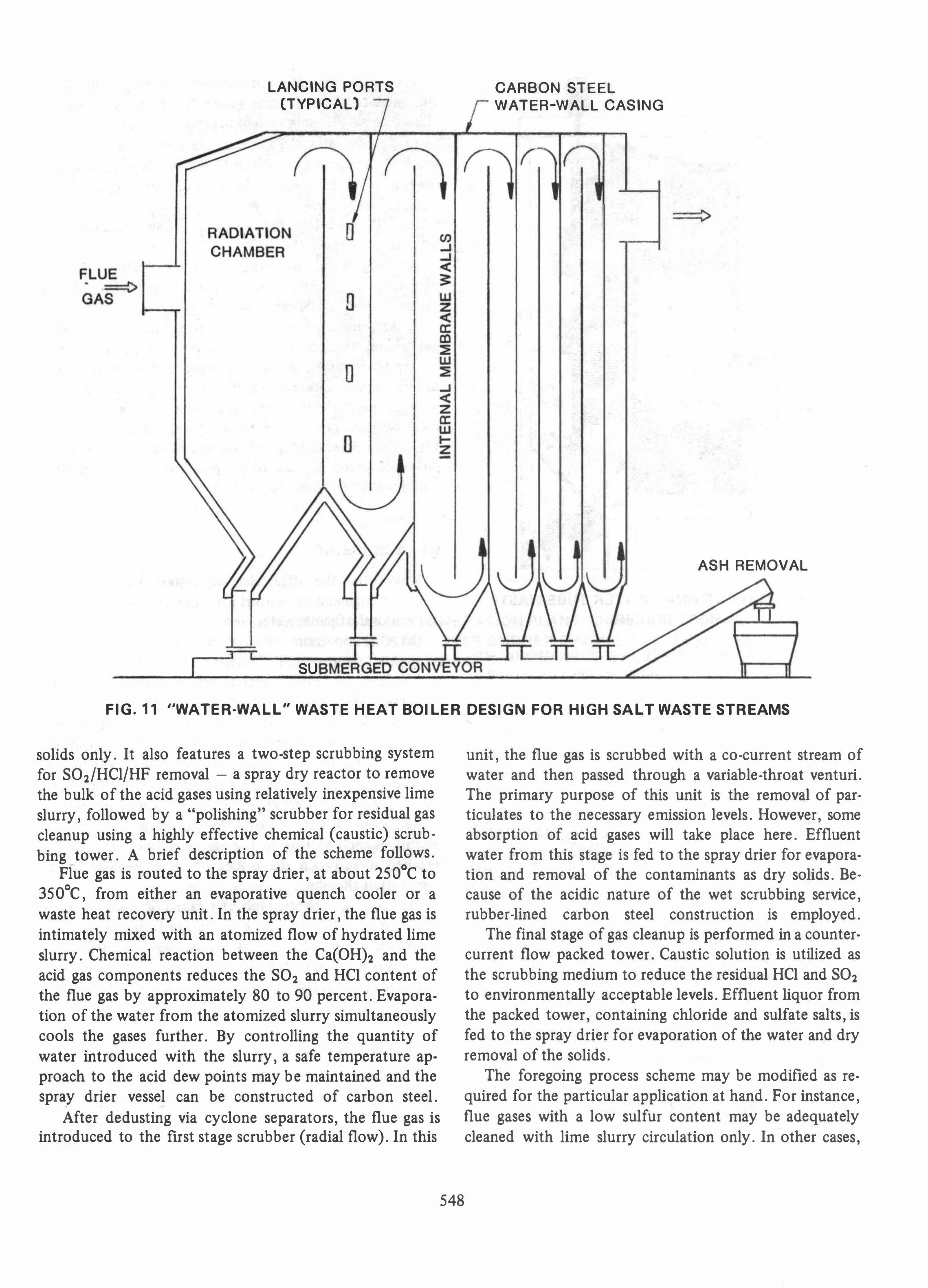
Design Characteristics
Figure 11 presents a sketch depicting the conceptual approach utilized for this application by several European
545
waste heat boiler suppliers. The boiler internals are encased in a steel shell constructed entirely of membrane type water walls, including the roof, front, back, side walls, as well as the bottom ash hoppers. With the excep· tion of the gas inlet duct, no refractory lining is provided. By maintaining essentially ambient conditions on the external side of the casing, lower metal temperatures may be maintained on the flue gas side. This factor, plus proper arrangement of the individual process heat duties for the boiler internals, will allow the unit to be operated in the metal temperature range between 200°C and 370°C. As a result, the need for exotic alloys suitable for severely corrosive environments is avoided, and the entire boiler can be constructed of carbon steel.
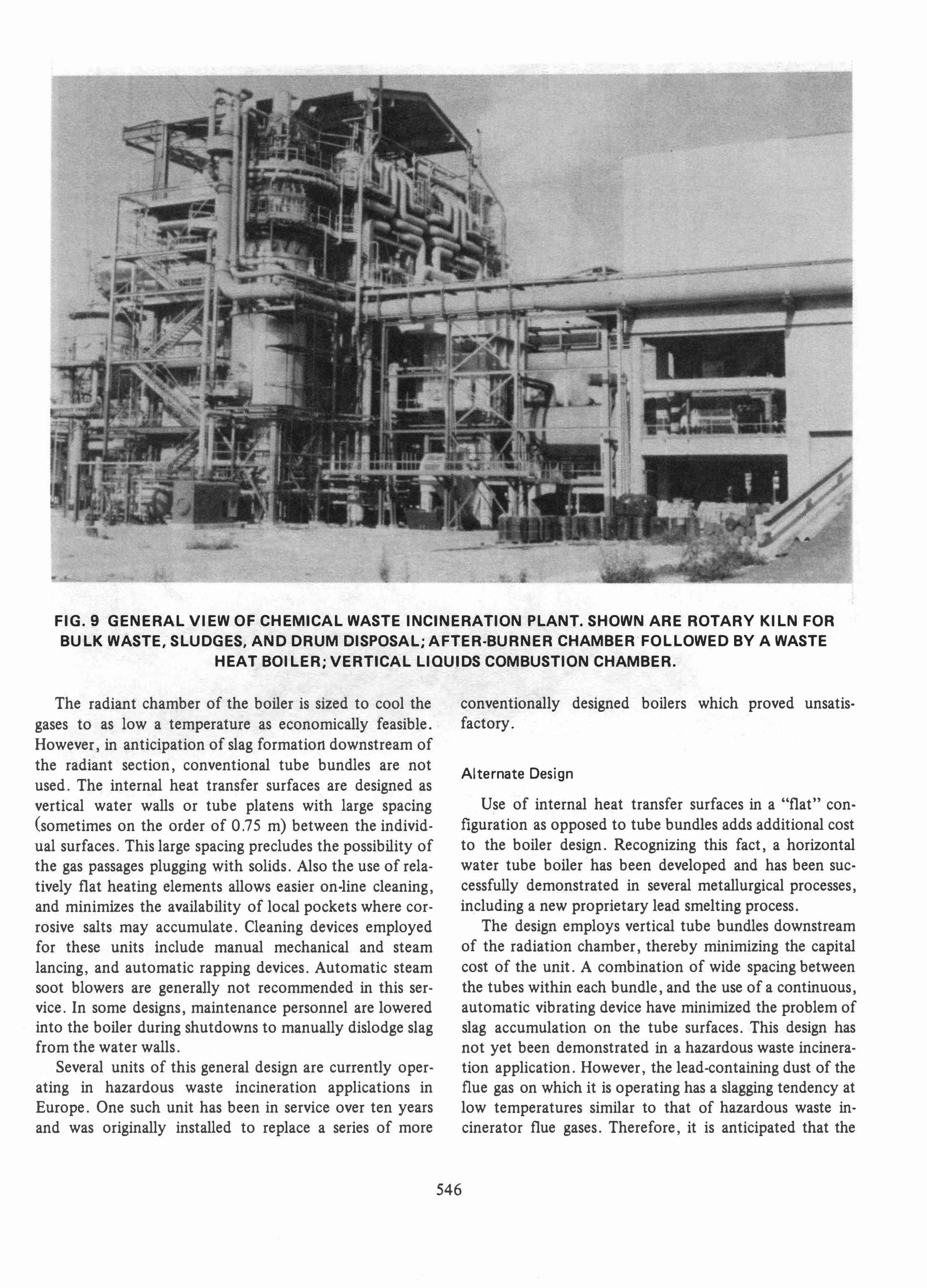
FIG.9 GENERAL VIEW OF CHEMICAL WASTE INCINERATION PLANT. SHOWN ARE ROTARY KILN FOR
BULK WASTE, SLUDGES, AND DRUM DISPOSAL; A FTER-BURNER CHAMBER FOLLOWED BY A WASTE
HEAT BOILER; VERTICAL LIQUIDS COMBUSTION CHAMBER.
The radiant chamber of the boiler is sized to cool the gases to as Iow a temperature as economically feasible. However, in anticipation of slag formation downstream of the radiant section, conventional tube bundles are not used. The internal heat transfer surfaces are designed as vertical water walls or tube platens with large spacing (sometimes on the order of 0.75 m) between the individual surfaces. This large spacing precludes the possibility of the gas passages plugging with solids. Also the use of relatively flat heating elements allows easier on-line cleaning, and minimizes the availability of local pockets where corrosive salts may accumulate. Cleaning devices employed for these units include manual mechanical and steam lancing, and automatic rapping devices. Automatic steam soot blowers are generally not recommended in this service. In some designs, maintenance personnel are lowered into the boiler during shutdowns to manually dislodge slag from the water walls.
Several units of this general design are currently operating in hazardous waste incineration applications in Europe. One such unit has been in service over ten years and was originally installed to replace a series of more
conventionally designed boilers which proved unsatisfactory.
Alternate Design
Use of internal heat transfer surfaces in a "flat" configuration as opposed to tube bundles adds additional cost to the boiler design. Recognizing this fact, a horizontal water tube boiler has been developed and has been successfully demonstrated in several metallurgical processes, including a new proprietary lead smelting process.
The design employs vertical tube bundles downstream of the radiation chamber, thereby minimizing the capital cost of the unit. A combination of wide spacing between the tubes within each bundle, and the use of a continuous, automatic vibrating device have minimized the problem of slag accumulation on the tube surfaces. This design has not yet been demonstrated in a hazardous waste incineration application. However, the lead-containing dust of the flue gas on which it is operating has a slagging tendency at low temperatures similar to that of hazardous waste incinerator flue gases. Therefore, it is anticipated that the
546
FLUE GAS
. ." " . , - ' "
. . ." .
.,
, - .
, . . .' . - : --- , . .
, • ..10. "II"',. ." ,. . � . ,�,'� , I . .. �". . " " , .. . .
�. ' . . � . • •
--
•
, .
. . . _ r · "
, .
•
FIG. 10 CONVENTIONAL WATER TUBE WASTE
HEAT BOILER
design will operate satisfactorily in such incinerator service, and will provide a substantial savings in the capital investment required.
In spite of the restrictions imposed on the heat recovery system, installation of such a unit can prove an economical investment. In a recently completed study the inclusion of a waste heat recovery system for the generation of electric power was investigated for an existing hazardous waste facility. Based on a total heat input to the system of 26 MM kJ/H, the unit was capable of producing approximately 26,000 kg/h of 34.5 bar/343°C steam to be utilized in an extraction-condensing turbogenerator. Approximately 5 MW of power is generated. After satisfying inplant steam and power requirements, a net capacity of 3 MW of power is available for sale to the local utility. Overall energy recovery from the flue gas is approximately 64 percent. In this particular case a payback period of 5 years, based on the installed cost investment, was calculated. This payback period is, of course, tied to the individual utility rates and will be reduced should those rates increase.
FLUE GAS CLEANING
Contaminants in the incineration waste gases depend,
547
of course, on the nature of the material being incinerated. For industrial wastes, it is generally necessary to design the waste gas cleaning system for the removal of:
(a) particulates, which may be present in the waste gases in the range of 2500 to 1 2,000 mg/Nm3, and which may have to be cleaned to an order of magnitude of 100 mg/Nm3 or less;
(b) HCl and HF, for which a removal efficiency of 99 percent is often dictated;
(c) S02 where the required removal efficiency may vary from 70 to 95 percent or greater, depending on the sulfur content of the feed .
A large number of process configurations for the offgas cleanup system are possible depending on the specific contaminants and the required degrees of removal. In addition, various site related factors must be considered, such as: availability of reagents (lime, soda ash, caustic, etc.); disposal possibilities for collected solids (sludge versus dry solids); leaching characteristics of these materials; possibilities for disposal of a liquid discharge versus a requirement for zero liquid discharge.
WET SCRUBBING
Most often, the offgas cleaning system will consist of: (a) A high-energy venturi scrubber designed for effec
tive removal of particulates, and (b) One or more absorption towers using suitable
scrubbing liquors and designed to provide sufficient staging and gas-liquid contact time for removal of acid gases (HCI, HF, S02)'
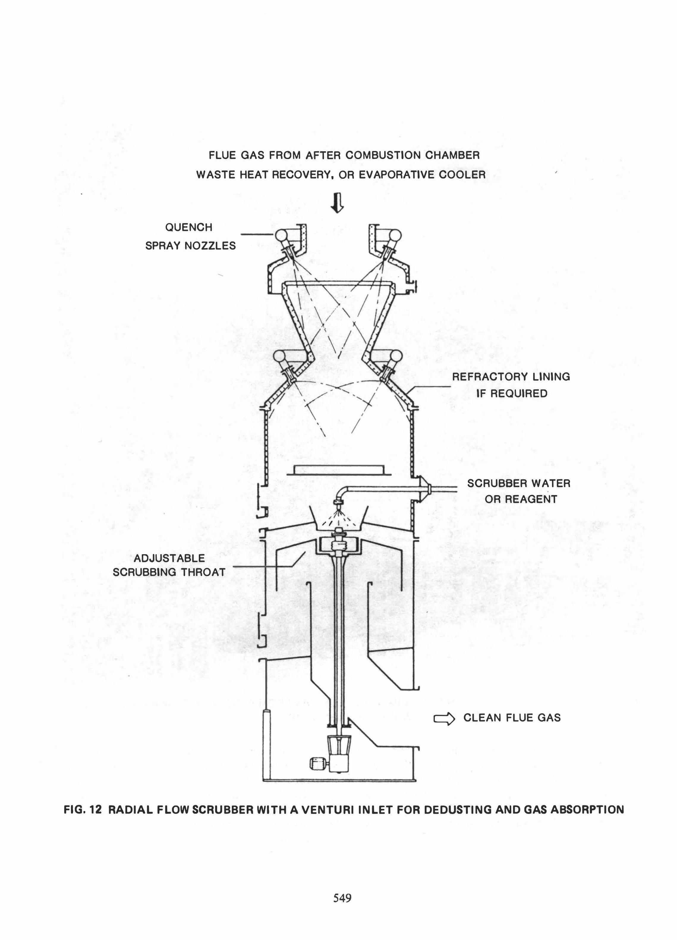
These two requirements can sometimes be satisfied in a single absorption/scrubbing tower. Figure 12 is an outline schematic of a Lurgi "Radial Flow Scrubber." The unit is designed for wet scrubbing of thermal process flue gases and is capable of both chemical absorption of impurities as well as particulate removal. By providing a brick-lined venturi quench section in the scrubber, the unit may be installed directly on the outlet of an incinerator aftercombustion chamber.
Figure 13 is a photograph of a radial flow scrubber installed in a chemical waste incineration facility operating in West Germany. The scrubber processes 70,000 Nm3/h of flue gases reducing the S02 content by 90 percent, and both the HCl and dust contents to 1 00 mg/Nm3 each.
SEMI-DRY PROCESS
The trend toward a highly flexible, zero liquid discharge gas cleaning system is typified by the process indicated in Fig. 1 4. This system discharges the collected particulates and the reacted acid gases in the form of dry
LANCING PORTS (TYPICAL)
SU
CARBON STEEL WATER-WALL CASING
ASH REMOVAL
FIG.11 "WATER-WALL" WASTE HEAT BOILER DESIGN FOR HIGH SALT WASTE STREAMS
solids only. It also features a two-step scrubbing system for S02/HCl/HF removal - a spray dry reactor to remove the bulk of the acid gases using relatively inexpensive lime slurry, followed by a "polishing" scrubber for residual gas cleanup using a highly effective chemical (caustic) scrubbing tower. A brief description of the scheme follows.
Flue gas is routed to the spray drier, at about 250°C to 350°C, from either an evaporative quench cooler or a waste heat recovery unit. In the spray drier, the flue gas is intimately mixed with an atomized flow of hydrated lime slurry. Chemical reaction between the Ca(OH)2 and the acid gas components reduces the S02 and HCl content of the flue gas by approximately 80 to 90 percent. Evaporation of the water from the atomized slurry simultaneously cools the gases further. By controlling the quantity of water introduced with the slurry, a safe temperature approach to the acid dew points may be maintained and the spray drier vessel can be constructed of carbon steel.
After de dusting via cyclone separators, the flue gas is introduced to the rust stage scrubber (radial flow). In this
548
unit, the flue gas is scrubbed with a co-current stream of water and then passed through a variable-throat venturi. The primary purpose of this unit is the removal of particulates to the necessary emission levels. However, some absorption of acid gases will take place here. Effluent water from this stage is fed to the spray drier for evaporation and removal of the contaminants as dry solids. Because of the acidic nature of the wet scrubbing service, rubber-lined carbon steel construction is employed.
The final stage of gas cleanup is performed in a countercurrent flow packed tower. Caustic solution is utilized as the scrubbing medium to reduce the residual HCl and S02 to environmentally acceptable levels. Effluent liquor from the packed tower, containing chloride and sulfate salts, is fed to the spray drier for evaporation of the water and dry removal of the solids.
The foregoing process scheme may be modified as required for the particular application at hand. For instance, flue gases with a low sulfur content may be adequately cleaned with lime slurry circulation only. In other cases,
•
FLUE GAS FROM AFTER COMBUSTION CHAMBER
WASTE HEAT RECOVERY, OR EVAPORATIVE COOLER ,
QUENCH
SPRAY NOZZLES
ADJUSTABLE
SCRUBBING THROAT
,
J
< / \. I
,
\ /
I
/ "
// " r--_
REFRACTORY LINING .,.---
IF REQUIRED
SCRUBBER WATER •
OR REAGENT
•
q CLEAN FLUE GAS
FIG. 12 RADIAL FLOW SCRUBBER WITH A VENTURI INLET FOR DEDUSTING AND GAS ABSORPTION
549
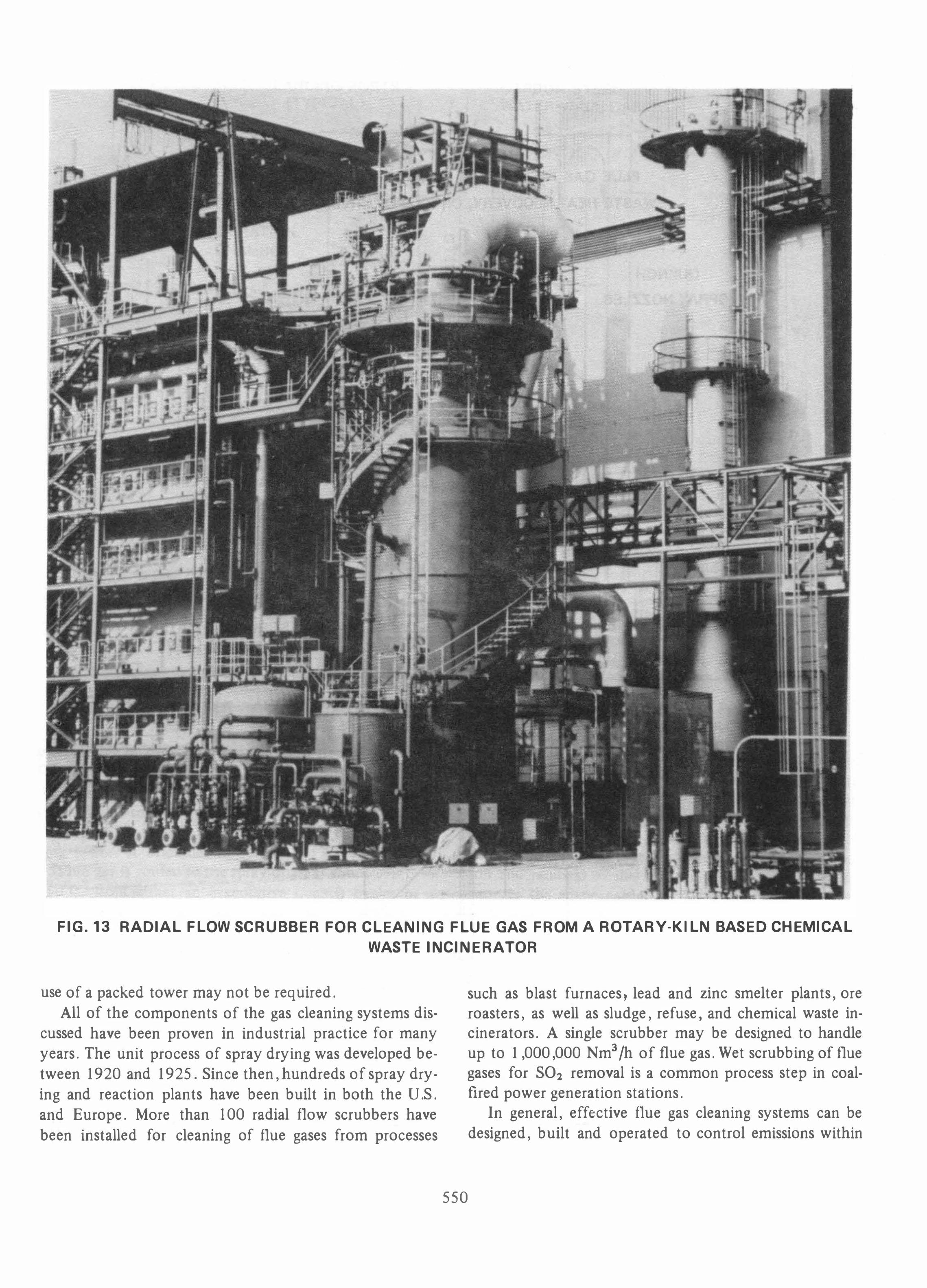
FIG. 13 RADIAL FLOW SCRUBBER FOR CLEANING FLUE GAS FROM A ROTARY-KILN BASED CHEMICAL
WASTE INCINERATOR
use of a packed tower may not be required. All of the components of the gas cleaning systems dis
cussed have been proven in industrial practice for many years. The unit process of spray drying was developed between 1920 and 1925. Since then, hundreds of spray drying and reaction plants have been built in both the U.S. and Europe. More than 100 radial flow scrubbers have been installed for cleaning of flue gases from processes
550
such as blast furnaces, lead and zinc smelter plants, ore roasters, as well as sludge, refuse, and chemical waste incinerators. A single scrubber may be designed to handle up to 1,000,000 Nm3/h of flue gas. Wet scrubbing of flue gases for S02 removal is a common process step in coalfired power generation stations.
In general, effective flue gas cleaning systems can be designed, built and operated to control emissions within

Ul
Ul
......
"DIR
TY"
FL
UE
GA
S
SPR
AY
DR
YE
R
DR
Y S
OL
IDS
TO
D
LSP
OS
AL
CY
CL
ON
E
TE
R
LIM
E M
AK
E-U
P
SY
ST
EM
RA
DIA
L F
LO
W
SC
RU
BB
ER
P
AC
KE
D T
OW
ER
•
FIG
. 14
S
IMP
LIF
IED
FL
OW
DIA
GR
AM
OF
SE
MI-
DR
Y F
LU
E G
AS
SC
RU
BB
ING
ST
AC
K
CA
US
TIC
MA
KE
-UP
SY
ST
EM
CL
EA
N
OF
FG
AS
regulatory requirements. However, it is essential that the maximum level of contaminants be established during the design phase to permit the proper selection and design of the gas cleanup train. From a control point of view, it is also important that fluctuations in feed composition to the incinerator plant be minimized as far as practicable, so as to maintain a steady operation and, hence, a relatively constant gas composition at the inlet to the gas cleaning train.
SUMMARY
Incineration technology for the various physical forms and chemical makeup of hazardous wastes exists, and has
been well proven in large-scale industrial facilities. Heat recovery from these plants is technically more difficult that heat recovery from combustion plants generating cleaner gas streams; however, the technology to accomplish this exists and has been proven. Similarly, satisfactory offgas cleanup technology is available and has been proven to meet regulatory standards.
Hazardous waste incineration plants can be operated in an 'environmentally sound manner using conventional chemical plant control methods. The technology has been practiced and proven in Europe (as indicated in the presented photographs) where the pressures of limited disposal sites and population densities encouraged earlier attention to the need for the design and construction of such facilities.
Kay Word.: Boller . Chlor ine. Combustion. Cyclone.
Dust • Emission • Engineer ing • Envir onment. Equip
ment • Hazar dous. Incineration. Incinerator. Par ticulate
Mattar • P er for mance. Sludge. Solid. State-of-the-Ar t.
Sulfur . Technology • Toxic . Waste Heat. Waterwall
552