overview of gsm, gprs, and umts - binyahyabinyahya.com/books/overview of gsm, gprs, and umts -...
TRANSCRIPT

Cisco OL-2947-01
C H A P T E R 2
sing)the
ed
ixed,
Overview of GSM, GPRS, and UMTS
The Cisco Mobile Exchange (CMX) architecture provides mobile wireless solutions for operators uGeneral Packet Radio Service (GPRS) and Universal Mobile Telecommunication System (UMTSaccess technologies. This chapter provides an overview of these technologies and their roles in evolution from second-generation (2G) to third-generation (3G) mobile wireless networks.
• Global System for Mobile Communications (GSM)—A digital, mobile, radio standard developfor mobile, wireless, voice communications
• GPRS—An extension of GSM networks that provides mobile, wireless, data communications
• UMTS—An extension of GPRS networks that moves toward an all-IP network by deliveringbroadband information, including commerce and entertainment services, to mobile users via fwireless, and satellite networks
This chapter includes the following sections:
• “Global Systems for Mobile Communications” section on page 2-2
– “GSM Technology Differentiator” section on page 2-3
– “GSM Network Elements” section on page 2-3
– “GSM Interfaces” section on page 2-6
– “GSM Data Services” section on page 2-7
• “General Packet Radio Service” section on page 2-7
– “GPRS Architecture” section on page 2-10
– “GPRS Terminals” section on page 2-13
– “Data Routing” section on page 2-14
– “GPRS Interfaces” section on page 2-17
– “GPRS Protocol Stacks” section on page 2-18
– “GPRS Tunneling Protocol” section on page 2-19
– “GPRS Access Modes” section on page 2-20
– “GPRS Access Point Name” section on page 2-20
– “GPRS Processes” section on page 2-21
• “Universal Mobile Telecommunication System” section on page 2-28
– “UMTS Services” section on page 2-28
– “UMTS Architecture” section on page 2-29
2-1Mobile Exchange (CMX) Solution Guide

Chapter 2 Overview of GSM, GPRS, and UMTSGlobal Systems for Mobile Communications
phoneecame
phonebile the
tionst
from
nare
th
he
Global Systems for Mobile CommunicationsIn the early 1980s, many countries in Europe witnessed a rapid expansion of analog cellular telesystems. However, each country developed its own system, and interoperability across borders ba limiting factor.
In 1982, the Conference of European Post and Telecommunications (CEPT), an association of teleand telegraph operators in Europe, established a working group to develop a new public land mosystem to span the continent. Because their working language was French, the group was calledGroupe Speciale Mobile (GSM).
The GSM group proposed the following criteria for the new mobile wireless system:
• good speech quality
• low cost for terminals and service
• international roaming
• handheld terminals
• support for introduction new services
• spectral efficiency
• compatibility with Integrated Digital Services Network (ISDN)
In 1989, the responsibility for GSM development was transferred to the European TelecommunicaStandards Institute (ETSI), and phase 1 of the GSM specification was published in 1990. The firscommercial service was launched in 1991.
When the official language of the GSM group changed from French to English, GSM was changedGroupe Speciale Mobile to Global System for Mobile Communications.
In 1994, phase 2 data/fax services were launched, and in 1995, the GSM phase 2 standard wascompleted. The first GSM services in the United States were launched.
GSM uses a combination of both the time division multiple access (TDMA) and frequency divisiomultiple access (FDMA) technologies. With this combination, more channels of communications available, and all channels are digital.
The GSM service is available in four frequency bands:
• 450-MHz—Upgrade of older analog cellular systems in Scandinavia
• 900-MHz—Original band used everywhere except North America and most of South America
• 1800-MHz—New band to increase capacity and competition used everywhere except NorthAmerica and most of South America
• 1900-MHz—Personal communications service band used in North America and much of SouAmerica
The higher frequency bands provide additional capacity and higher subscriber densities.
One of the unique benefits of GSM service is its capability for international roaming because of troaming agreements established between the various GSM operators worldwide.
2-2Cisco Mobile Exchange (CMX) Solution Guide
OL-2947-01

Chapter 2 Overview of GSM, GPRS, and UMTSGlobal Systems for Mobile Communications
marta slot
twork
smart
e
or a
to the
alled ating
GSM Technology DifferentiatorOne of the advantages of GSM is that it offers a subscriber identity module (SIM), also known as a scard. The smart card contains a computer chip and some non-volatile memory and is inserted intoin the base of the mobile handset.
The memory on the smart card holds information about the subscriber that enables a wireless neto provide subscriber services. The information includes:
• The subscriber’s identity number
• The telephone number
• The original network to which the subscriber is subscribed
A smart card can be moved from one handset to another. A handset reads the information off thecard and transmits it to the network.
GSM Network ElementsA GSM network consists of the following network components:
• Mobile station (MS)
• Base transceiver station (BTS)
• Base station controller (BSC)
• Base station subsystem (BSS)
• Mobile switching center (MSC)
• Authentication center (AuC)
• Home location register (HLR)
• Visitor location register (VLR)
Mobile Station
The mobile station (MS) is the starting point of a mobile wireless network. The MS can contain thfollowing components:
• Mobile terminal (MT)—GSM cellular handset
• Terminal equipment (TE)—PC or personal digital assistant (PDA)
The MS can be two interconnected physical devices (MT and TE) with a point-to-point interface single device with both functions integrated.
Base Transceiver Station
When a subscriber uses the MS to make a call in the network, the MS transmits the call requestbase transceiver station (BTS). The BTS includes all the radio equipment (i.e., antennas, signalprocessing devices, and amplifiers) necessary for radio transmission within a geographical area ccell. The BTS is responsible for establishing the link to the MS and for modulating and demodularadio signals between the MS and the BTS.
2-3Cisco Mobile Exchange (CMX) Solution Guide
OL-2947-01

Chapter 2 Overview of GSM, GPRS, and UMTSGlobal Systems for Mobile Communications
s theBTSsing
. Theoding
andthe
SCs.
ntedfrom
rk. Ittynamic
s for
outR isVLR
shipf the
Base Station Controller
The base station controller (BSC) is the controlling component of the radio network, and it manageBTSs. The BSC reserves radio frequencies for communications and handles the handoff betweenwhen an MS roams from one cell to another. The BSC is responsible for paging the MS for incomcalls.
Base Station Subsystem
A GSM network is comprised of many base station subsystems (BSSs), each controlled by a BSCBSS performs the necessary functions for monitoring radio connections to the MS, coding and decvoice, and rate adaptation to and from the wireless network. A BSS can contain several BTSs.
Mobile Switching Center
The mobile switching center (MSC) is a digital ISDN switch that sets up connections to other MSCsto the BSCs. The MSCs form the wired (fixed) backbone of a GSM network and can switch calls topublic switched telecommunications network (PSTN). An MSC can connect to a large number of B
Equipment Identity Register
The equipment identity register (EIR) is a database that stores the international mobile equipmeidentities (IMEIs) of all the mobile stations in the network. The IMEI is an equipment identifier assignby the manufacturer of the mobile station. The EIR provides security features such as blocking callshandsets that have been stolen.
Home Location Register
The home location register (HLR) is the central database for all users to register to the GSM netwostores static information about the subscribers such as the international mobile subscriber identi(IMSI), subscribed services, and a key for authenticating the subscriber. The HLR also stores dysubscriber information (i.e., the current location of the mobile subscriber).
Authentication Center
Associated with the HLR is the authentication center (AuC); this database contains the algorithmauthenticating subscribers and the necessary keys for encryption to safeguard the user input forauthentication.
Visitor Location Register
The visitor location register (VLR) is a distributed database that temporarily stores information abthe mobile stations that are active in the geographic area for which the VLR is responsible. A VLassociated with each MSC in the network. When a new subscriber roams into a location area, theis responsible for copying subscriber information from the HLR to its local database. This relationbetween the VLR and HLR avoids frequent HLR database updates and long distance signaling ouser information, allowing faster access to subscriber information.
2-4Cisco Mobile Exchange (CMX) Solution Guide
OL-2947-01

Chapter 2 Overview of GSM, GPRS, and UMTSGlobal Systems for Mobile Communications
riberstion
elessther
The HLR, VLR, and AuC comprise the management databases that support roaming (includinginternational roaming) in the GSM network. These databases authenticate calls while GSM subscroam between the private network and the public land mobile network (PLMN). The types of informathey store include subscriber identities, current location area, and subscription levels.
Network and Switching Subsystem
The network and switching subsystem (NSS) is the heart of the GSM system. It connects the wirnetwork to the standard wired network. It is responsible for the handoff of calls from one BSS to anoand performs services such as charging, accounting, and roaming.
Figure 2-1 shows a GSM network and the network elements it contains.
Figure 2-1 GSM Network Elements
2-5Cisco Mobile Exchange (CMX) Solution Guide
OL-2947-01

Chapter 2 Overview of GSM, GPRS, and UMTSGlobal Systems for Mobile Communications
ential. and
arateols.
inkple,.The
ween(SS7)
DN).l
theartlingtems.h isSS7
GSM InterfacesThe GSM uses various interfaces for communication among its network elements.Figure 2-2 showsthese interfaces.
Figure 2-2 GSM Interfaces
Mobile wireless communication occurs over the interfaces between the network elements in a sequmanner. InFigure 2-2, the MS transmits to the BTS, the BTS to the BSC, and the BSC to the MSCCommunications also occur over the interfaces to the management databases (HLR, VLR, AuC,EIR). Communications might traverse multiple MSCs but ultimately must reach the gateway MSC(GMSC). The GMSC provides the gateway to the public switched telephone network (PSTN). A sepinterface exists between each pair of elements, and each interface requires its own set of protoc
In the BSS block, mobile communication occurs over the air interface to the BTS using the ISDN LAccess Procedure-D mobile (LAP-Dm). This traffic channel carries speech and data. In this examvoice operates at full-rate 13 kbps (supported by LAP-Dm), and data operates at full-rate 9.6 kbpsBTS communicates to the BSC over theAbis interface using the ISDN LAP-D signaling protocol. TheBSC communicates to the GMSC via the transcoder rate adapter unit (TRAU), which translates bet16 kbps on the BTS side to 64 kbps on the GMSC side. This interface uses the signaling system 7protocol, which defines call set-up and call services across the interface.
At the NSS, the GMSC is the central node. Link-level traffic and signaling control occurs over theinterface between the GMSC and MSC and the interface to the external network (PSTN, ISDN or PDifferent signaling protocols are used on the interfaces. Some NSS interfaces involve only controsignaling protocols with no traffic. For example, no traffic is generated on the interfaces betweenGMSC, HLR, and VLR. Instead, these interfaces carry only signaling using the Mobile Application P(MAP) of the SS7 protocol. The MAP is specified in IS-41 and defines the application layer, signaprotocols, and procedures for registering mobile users and handling handoffs between cellular sysThe GMSC establishes call traffic (at 64 kbps) onto the PSTN via the ISDN user part (ISUP), whican SS7-based protocol. The GMSC and MSC exchange traffic (over LAP-D at 64 kbps) and use (MAP and ISUP) control.
2-6Cisco Mobile Exchange (CMX) Solution Guide
OL-2947-01

Chapter 2 Overview of GSM, GPRS, and UMTSGeneral Packet Radio Service
heion of
d use.cess a
for
or
al
st
izenewes to
GSM Data ServicesGSM networks handle both voice and data traffic requirements of the mobile communication byproviding two modes of operation:
• Circuit switched (high-speed circuit switched data)
• Packet switched (GPRS)
Circuit switching provides the customer with a dedicated channel all the way to the destination. Tcustomer has exclusive use of the circuit for the duration of the call, and is charged for the duratthe call.
With packet switching, the operator assigns one or more dedicated channels specifically for shareThese channels are up and running 24 hours a day, and when you need to transfer data, you acchannel and transmit your data. Packet switching is more efficient than circuit switching.
The standard data rate of a GSM channel is 22.8 kbps.
General Packet Radio ServiceThe general packet radio system (GPRS) provides packet radio access for mobile Global SystemMobile Communications (GSM) and time-division multiple access (TDMA) users. In addition toproviding new services for today's mobile user, GPRS is important as a migration step towardthird-generation (3G) networks. GPRS allows network operators to implement an IP-based corearchitecture for data applications, which will continue to be used and expanded for 3G services fintegrated voice and data applications. The GPRS specifications are written by the EuropeanTelecommunications Standard Institute (ETSI), the European counterpart of the American NationStandard Institute (ANSI).
GPRS is the first step toward an end-to-end wireless infrastructure and has the following goals:
• Open architecture
• Consistent IP services
• Same infrastructure for different air interfaces
• Integrated telephony and Internet infrastructure
• Leverage industry investment in IP
• Service innovation independent of infrastructure
Benefits of GPRSThe GPRS provides the following benefits:
• Overlays on the existing GSM network to provide high-speed data service
• Always on, reducing the time spent setting up and taking down connections
• Designed to support bursty applications such as e-mail, traffic telematics, telemetry, broadcaservices, and web browsing that do not require detected connection.
By implementing Cisco GPRS products and related solutions, mobile service providers can optimtheir networks to deploy high quality mobile voice and data services. They can also benefit from operating efficiencies, peer-to-peer IP-based architecture for scalability, and IP standard interfacbilling and customer support.
2-7Cisco Mobile Exchange (CMX) Solution Guide
OL-2947-01

Chapter 2 Overview of GSM, GPRS, and UMTSGeneral Packet Radio Service
bileristics
nd
an becess to
These
der
obileee
l, fax,ks arealls by
ers areta ands an
GPRS ApplicationsGPRS enables a variety of new and unique services to the mobile wireless subscriber. These moservices have unique characteristics that provide enhanced value to customers. These characteinclude the following:
• Mobility—The ability to maintain constant voice and data communications while on the move
• Immediacy—Allows subscribers to obtain connectivity when needed, regardless of location awithout a lengthy login session
• Localization—Allows subscribers to obtain information relevant to their current location
The combination of these characteristics provides a wide spectrum of possible applications that coffered to mobile subscribers. The core network components offered by Cisco enable seamless acthese applications, whether they reside in the service provider's network or the public Internet.
In general, applications can be separated into two high-level categories: corporate and consumer.include:
• Communications—E-mail; fax; unified messaging; intranet/Internet access
• Value-added services—Information services; games
• E-commerce—Retail; ticket purchasing; banking; financial trading
• Location-based applications—Navigation; traffic conditions; airline/rail schedules; location fin
• Vertical applications—Freight delivery; fleet management; sales-force automation
• Advertising
Communications
Communications applications include those in which it appears to users that they are using the mcommunications network as a pipeline to access messages or information. This differs from thosapplications in which users believe that they are accessing a service provided or forwarded by thnetwork operator.
Intranet Access
The first stage of enabling users to maintain contact with their offices is through access to e-maiand voice mail using unified messaging systems. Increasingly, files and data on corporate networbecoming accessible through corporate intranets. These intranets can be protected through firewenabling secure tunnels or virtual private networks (VPNs).
Internet Access
As a critical mass of users is approached, more and more applications aimed at general consumbeing placed on the Internet. The Internet is becoming an effective tool for accessing corporate damanipulating product and service information. More recently, companies are using the Internet aenvironment for conducting business through e-commerce.
2-8Cisco Mobile Exchange (CMX) Solution Guide
OL-2947-01

Chapter 2 Overview of GSM, GPRS, and UMTSGeneral Packet Radio Service
tly oroviderines
short accessor sendesof their
rvices
itions.s or
tes or
n key
, or
ationstions.
e data
ns areeounts,
Email and Fax
E-mail on mobile networks may take one of two forms. E-mail can be sent to a mobile user directhe user can have an e-mail account maintained by the network operator or their Internet service pr(ISP). In the latter case, a notification is forwarded to the mobile terminal and includes the first few lof the e-mail, details of the sender, the date and time, and the subject. Fax attachments can alsoaccompany e-mails.
Unified Messaging
Unified messaging provides a single mailbox for all messages, including voice mail, faxes, e-mail,message service (SMS), and pager messages. Unified messaging systems allow for a variety ofmethods to recover messages of different types. Some use text-to-voice systems to read e-mail faxes over a normal phone line. Most allow the user to query the contents of the various mailboxthrough data access such as the Internet. Others can be configured to alert the user on the devicechoice when messages are received.
Value Added Services
Value-added services refer to the content provided by network operators to increase the value of seto their subscribers. Two terms that are frequently used to describe delivery of data applications arepushandpull, as defined below.
• Pushdescribes the transmission of data at a predetermined time or under predetermined condIt also refers to the unsolicited supply of advertising (for example, delivery of news as it occurstock values when they fall below a preset value).
• Pull describes the request for data in real time by the user (for example, checking stock quodaily news headlines).
To be valuable to subscribers, this content must possess several characteristics:
• Personalized information that is tailored to the user (for example, a stock ticker that focusses oquotes and news or an e-commerce application that knows a user's profile)
• Localized content that is based on a user's current location and includes maps, hotel findersrestaurant reviews
• Menu screens that are intuitive and easy to navigate
• Security for e-commerce sites for the exchange of financial or other personal information
Several value-added services are outlined in the following sections.
E-commerce
E-commerce is defined as business conducted on the Internet or data service. This includes applicin which a contract is established for the purchase of goods and services and online banking applicaThese applications require user authentication and secure transmission of sensitive data over thconnection.
Banking
The banking industry is interested in promoting electronic banking because electronic transactioless costly to conduct than personal transactions in a bank. Specific banking functions that can baccomplished over a wireless connection include balance checking, money transfers between accbill payment, and overdraft alert.
2-9Cisco Mobile Exchange (CMX) Solution Guide
OL-2947-01

Chapter 2 Overview of GSM, GPRS, and UMTSGeneral Packet Radio Service
ationthele
s andicles
port
ment
ir
ance
mers. For
orkre the
buildorrk
Financial Trading
The immediacy of transactions over the Internet and the requirement for up-to-the-minute informhas made the purchasing of stocks online a popular application. By coupling push services with ability to make secure transactions from the mobile terminal, a service that is unique to the mobienvironment can be provided.
Location-Based Services and Telematics
Location-based services provide the ability to link push or pull information services with a user'slocation. Examples include hotel and restaurant finders, roadside assistance, and city-specific newinformation. This technology also has vertical applications. These allow, for example, tracking vehin a fleet or managing the operations of a large workforce.
Vertical Applications
In the mobile environment, vertical applications apply to systems using mobile architectures to supthe specific tasks within a company. Examples of vertical applications include:
• Sales support—Configuring stock and product information for sales staff, integrating appointdetails, and placing orders remotely
• Dispatching—Communicating job details such as location and scheduling and permittinginformation queries to support the job
• Fleet management—Controlling a fleet of delivery or service staff and vehicle, monitoring thelocations, and scheduling their work
• Parcel delivery—Tracking the locations of packages for customers and monitoring the performof the delivery system
Advertising
Advertising services are offered as a push information service. Advertising may be offered to custoto subsidize the cost of voice or other information services. Advertising may be location sensitiveexample, a user entering a mall can receive advertisements specific to the stores in that mall.
GPRS ArchitectureGPRS is a data network that overlays a second-generation GSM network. This data overlay netwprovides packet data transport at rates from 9.6 to 171 kbps. Additionally, multiple users can shasame air-interface resources simultaneously.
GPRS attempts to reuse the existing GSM network elements as much as possible, but to effectivelya packet-based mobile cellular network, some new network elements, interfaces, and protocols fhandling packet traffic are required. Therefore, GPRS requires modifications to numerous netwoelements as summarized inTable 2-1 and shown inFigure 2-3.
2-10Cisco Mobile Exchange (CMX) Solution Guide
OL-2947-01

Chapter 2 Overview of GSM, GPRS, and UMTSGeneral Packet Radio Service
.
theete
nd
y
Figure 2-3 GPRS Reference Architecture
Table 2-1 GPRS Network Elements
GSM Network Element Modification or Upgrade Required for GPRS.
Terminal Equipment (TE) New terminal equipment is required to access GPRS services.
These new terminals will be backward compatible with GSM for voicecalls.
BTS A software upgrade is required in the existing base transceiver site
BSC The base station controller (BSC) requires a software upgrade andinstallation of new hardware called the packet control unit (PCU). ThPCU directs the data traffic to the GPRS network and can be a separahardware element associated with the BSC.
GPRS Support Nodes (GSNs) The deployment of GPRS requires the installation of new corenetwork elements called the serving GPRS support node (SGSN) agateway GPRS support node (GGSN).
Databases (HLR, VLR, etc.) All the databases involved in the network will require softwareupgrades to handle the new call models and functions introduced bGPRS.
2-11Cisco Mobile Exchange (CMX) Solution Guide
OL-2947-01

Chapter 2 Overview of GSM, GPRS, and UMTSGeneral Packet Radio Service
ace orpporttop
ides aBTS
airwever,) peray
ded:
s toPRSf theirndingisSC.
servicessary
nsovidedlater
GPRS Subscriber Terminals
New terminals are required because existing GSM phones do not handle the enhanced air interfpacket data. A variety of terminals can exist, including a high-speed version of current phones to suhigh-speed data access, a new PDA device with an embedded GSM phone, and PC cards for lapcomputers. These terminals are backward compatible for making voice calls using GSM.
GPRS Base Station Subsystem
Each BSC requires the installation of one or more PCUs and a software upgrade. The PCU provphysical and logical data interface to the base station subsystem (BSS) for packet data traffic. Thecan also require a software upgrade but typically does not require hardware enhancements.
When either voice or data traffic is originated at the subscriber terminal, it is transported over theinterface to the BTS, and from the BTS to the BSC in the same way as a standard GSM call. Hoat the output of the BSC, the traffic is separated; voice is sent to the mobile switching center (MSCstandard GSM, and data is sent to a new device called the SGSN via the PCU over a Frame Relinterface.
GPRS Support Nodes
In the core network, the existing MSCs are based on circuit-switched central-office technology ancannot handle packet traffic. Two new components, called GPRS support nodes (GSNs), are add
• Serving GPRS support node (SGSN)
• Gateway GPRS support node (GGSN)
Serving GPRS Support Node
The SGSN delivers packets to mobile stations (MSs) within its service area. SGSNs send queriehome location registers (HLRs) to obtain profile data of GPRS subscribers. SGSNs detect new GMSs in a given service area, process registration of new mobile subscribers, and keep records olocations inside a predefined area. The SGSN performs mobility management functions such as haoff a roaming subscriber from the equipment in one cell to the equipment in another. The SGSN connected to the base station subsystem through a Frame Relay connection to the PCU in the B
Gateway GPRS Support Node
GGSNs are used as interfaces to external IP networks such as the public Internet, other mobile providers' GPRS services, or enterprise intranets. GGSNs maintain routing information that is neceto tunnel the protocol data units (PDUs) to the SGSNs that service particular MSs. Other functioinclude network and subscriber screening and address mapping. One or more GGSNs can be prto support multiple SGSNs. More detailed descriptions of the SGSN and GGSN are provided in asection.
2-12Cisco Mobile Exchange (CMX) Solution Guide
OL-2947-01

Chapter 2 Overview of GSM, GPRS, and UMTSGeneral Packet Radio Service
types.PRS
. Thise orirtual
e ofn, andctede or
to.ult)
port of
of the data
the
m of a to bered byhone to
rte in
GPRS TerminalsThe termterminal equipment is generally used to refer to the variety of mobile phones and mobilestations that can be used in a GPRS environment. The equipment is defined by terminal classes andCisco’s gateway GPRS serving node (GGSN) and data network components interoperate with Gterminals that meet the GPRS standards.
Three classes of GPRS terminals are provided: Class A, Class B, or Class C.
Class A Terminals
Class A terminals support GPRS and other GSM services (such as SMS and voice) simultaneouslysupport includes simultaneous attach, activation, monitor, and traffic. Class A terminals can makreceive calls on two services simultaneously. In the presence of circuit-switched services, GPRS vcircuits are held (i.e., placed on hold) instead of being cleared.
Class B Terminals
Class B terminals can monitor GSM and GPRS channels simultaneously but can support only onthese services at a time. Therefore, a Class B terminal can support simultaneous attach, activatiomonitor, but not simultaneous traffic. As with Class A, the GPRS virtual circuits are not disconnewhen circuit-switched traffic is present. Instead, they are switched to busy mode. Users can makreceive calls on either a packet or a switched call type sequentially, but not simultaneously.
Class C Terminals
Class C terminals support only sequential attach. The user must select which service to connectTherefore, a Class C terminal can make or receive calls from only the manually selected (or defaservice. The service that is not selected is unreachable. The GPRS specifications state that supSMS is optional for Class C terminals.
GPRS Device Types
In addition to the three terminal classes, each handset has a unique form (housing design). Someforms are similar to current mobile wireless devices, while others will evolve to use the enhancedcapabilities of GPRS.
The earliest available type is closely related to the current mobile phone. These are available in standard form with a numeric keypad and a relatively small display.
PC cards are credit card-sized hardware devices that connect through a serial cable to the bottomobile phone. Data cards for GPRS phones enable laptops and other devices with PC card slotsconnected to mobile GPRS-capable phones. Card phones provide functions similar to those offePC cards without requiring a separate phone. These devices may require an ear piece and micropsupport voice services.
Smart phones are mobile phones with built-in voice, nonvoice, and Web-browsing services. Smaphones integrate mobile computing and mobile communications into a single terminal. They comvarious form factors, which may include a keyboard or an icon drive screen.
2-13Cisco Mobile Exchange (CMX) Solution Guide
OL-2947-01

Chapter 2 Overview of GSM, GPRS, and UMTSGeneral Packet Radio Service
ifice.such
eldevices
ability.
obileent.
atesS. ItGSN
).
Host
t the
h is
rving
rsssaryRS
to
The increase in machine-to-machine communications has led to the adoption of application-specdevices. Theseblack-box devices lack a display, keypad, and voice accessories of a standard phonCommunication is accomplished through a serial cable. Applications such as meter reading utilizeblack-box devices.
Personal digital assistants (PDAs), such as the Palm Pilot series or Handspring Visor, and handhcommunications devices are data-centric devices that are adding mobile wireless access. These dcan either connect with a GPRS-capable mobile phone via a serial cable or integrate GPRS capAccess can be gained via a PC card or a serial cable to a GPRS-capable phone.
Data RoutingOne of the main requirements in the GPRS network is the routing of data packets to and from a muser. The requirement can be divided into two areas: data packet routing and mobility managem
Data Packet Routing
The main functions of the GGSN involve interaction with the external data network. The GGSN updthe location directory using routing information supplied by the SGSNs about the location of an Mroutes the external data network protocol packet encapsulated over the GPRS backbone to the Scurrently serving the MS. It also decapsulates and forwards external data network packets to theappropriate data network and collects charging data that is forwarded to a charging gateway (CG
In Figure 2-4, three routing schemes are illustrated:
• Mobile-originated message (path 1)—This path begins at the GPRS mobile and ends at the
• Network-initiated message when the MS is in its home network (path 2)—This path begins aHost and ends at the GPRS mobile
• Network-initiated message when the MS roams to another GPRS network (path 3)—This patindicated by the dotted line
In these examples, the operator's GPRS network consists of multiple GSNs (with a gateway and sefunctionality) and an intra-operator backbone network.
GPRS operators allow roaming through an inter-operator backbone network. The GPRS operatoconnect to the inter-operator network through a border gateway (BG), which can provide the neceinterworking and routing protocols (for example, border gateway protocol [BGP]). In the future, GPoperators might implement quality of service (QoS) mechanisms over the inter-operator networkensure service-level agreements (SLAs). The main benefits of the architecture are its flexibility,scalability, interoperability, and roaming attributes.
2-14Cisco Mobile Exchange (CMX) Solution Guide
OL-2947-01

Chapter 2 Overview of GSM, GPRS, and UMTSGeneral Packet Radio Service
alledlifies
sharee of
Figure 2-4 Routing of Data Packets between a Fixed Host and a GPRS MS
The GPRS network encapsulates all data network protocols into its own encapsulation protocol cthe GPRS tunneling protocol (GTP). The GTP ensures security in the backbone network and simpthe routing mechanism and the delivery of data over the GPRS network.
Mobility Management
The operation of the GPRS is partly independent of the GSM network. However, some proceduresthe network elements with current GSM functions to increase efficiency and to make optimum usfree GSM resources (such as unallocated time slots).
An MS has three states in the GPRS system (Figure 2-5):
• Active
• Standby
• Idle
The three-state model is unique to packet radio; GSM uses a two-state model (idle or active).
Figure 2-5 GPRS States in a Mobile Station
2-15Cisco Mobile Exchange (CMX) Solution Guide
OL-2947-01

Chapter 2 Overview of GSM, GPRS, and UMTSGeneral Packet Radio Service
te. In
dataicatedngwnlink
acketuse isllocatesessage.. The
ne or
ecausea. Onactive
-basedSGSNn
ublicstes notorks.
n theGSN
nds aits
neting anew
Active State
Data is transmitted between an MS and the GPRS network only when the MS is in the active stathe active state, the SGSN knows the cell location of the MS.
Packet transmission to an active MS is initiated by packet paging to notify the MS of an incomingpacket. The data transmission proceeds immediately after packet paging through the channel indby the paging message. The purpose of the paging message is to simplify the process of receivipackets. The MS listens to only the paging messages instead of to all the data packets in the dochannels. This reduces battery usage significantly.
When an MS has a packet to transmit, it must access the uplink channel (i.e., the channel to the pdata network where services reside). The uplink channel is shared by a number of MSs, and its allocated by a BSS. The MS requests use of the channel in a random access message. The BSS aan unused channel to the MS and sends an access grant message in reply to the random access mThe description of the channel (one or multiple time slots) is included in the access grant messagedata is transmitted on the reserved channels.
Standby State
In the standby state, only the routing area of the MS is known. (The routing area can consist of omore cells within a GSM location area).
When the SGSN sends a packet to an MS that is in the standby state, the MS must be paged. Bthe SGSN knows the routing area of the MS, a packet paging message is sent to the routing arereceiving the packet paging message, the MS relays its cell location to the SGSN to establish thestate.
The main reason for the standby state is to reduce the load in the GPRS network caused by cellrouting update messages and to conserve the MS battery. When an MS is in the standby state, theis informed of only routing area changes. By defining the size of the routing area, the operator cacontrol the number of routing update messages.
Idle State
In the idle state, the MS does not have a logical GPRS context activated or any packet-switched pdata network (PSPDN) addresses allocated. In this state, the MS can receive only those multicamessages that can be received by any GPRS MS. Because the GPRS network infrastructure doknow the location of the MS, it is not possible to send messages to the MS from external data netw
Routing Updates
When an MS that is in an active or a standby state moves from one routing area to another withiservice area of one SGSN, it must perform a routing update. The routing area information in the Sis updated, and the success of the procedure is indicated in the response message.
A cell-based routing update procedure is invoked when an active MS enters a new cell. The MS seshort message containing the identity of the MS and its new location through GPRS channels to current SGSN. This procedure is used only when the MS is in the active state.
The inter-SGSN routing update is the most complicated routing update. The MS changes from oSGSN area to another, and it must establish a new connection to a new SGSN. This means creanew logical link context between the MS and the new SGSN and informing the GGSN about the location of the MS.
2-16Cisco Mobile Exchange (CMX) Solution Guide
OL-2947-01

Chapter 2 Overview of GSM, GPRS, and UMTSGeneral Packet Radio Service
pportPRS
work
s an
GPRS InterfacesThe GPRS architecture consists of signaling interfaces with various protocols that control and suthe transmission of packets across the networks and to the mobile stations. The interfaces in a Gnetwork are:
• Ga—Interface between GSN nodes (GGSN, SGSN) and charging gateway (CG)
• Gb—Interface between SGSN and BSS (PCU); normally uses Frame Relay
• Gc—Interface between GGSN and HLR
• Gi—Interface between GPRS (GGSN) and an external packet data network (PDN)
• Gn—Interface between two GSN nodes, i.e., GGSN and SGSN; this connects into the intra-netbackbone, for example, an Ethernet network
• Gp—Interface between two GSN nodes in different PLMNs; this is via border gateways and iinter-PLMN network backbone
• Gr—Interface between SGSN and HLR
• Gs—Interface between SGSN and the MSC/VLR
• Gf—Interface between SGSN and EIR
Figure 2-6 shows these interfaces.
Figure 2-6 GPRS Interfaces
2-17Cisco Mobile Exchange (CMX) Solution Guide
OL-2947-01

Chapter 2 Overview of GSM, GPRS, and UMTSGeneral Packet Radio Service
SN.neling
ed,arehedoesXR
igh
be a
GPRS Protocol StacksFigure 2-7 shows the GPRS protocol stack and end-to-end message flows from the MS to the GGThe protocol between the SGSN and GGSN using the Gn interface is GTP. This is a Layer 3 tunprotocol similar to L2TP.
Figure 2-7 GPRS Network Protocol Stack
AlthoughFigure 2-7 defines the Gn and Gi interface as IP, the underlying protocols are not specifiproviding flexibility with the physical medium. The GGSN software runs on a Cisco 7206VXR hardwplatform, which provides a wide range of supported physical interfaces and a high port density. TGGSN software uses a virtual template interface, which is a logical interface within the router andnot depend on the physical medium directly. A list of supported physical interfaces for the 7206Vcan be found at this URL:http://www.cisco.com/univercd/cc/td/doc/product/core/7200vx/portadpt/index.htm.
The most common physical interface used with GPRS is Fast Ethernet. This interface provides hbandwidth, low cost, and universal connectivity to other vendor equipment. For the Gi interface,common interfaces are Serial, E1/T1 or Ethernet. Running over the physical WAN interfaces canwide range of protocols including Frame Relay, ISDN, and HDLC.
2-18Cisco Mobile Exchange (CMX) Solution Guide
OL-2947-01

Chapter 2 Overview of GSM, GPRS, and UMTSGeneral Packet Radio Service
w86).
en the
ation. TIDield
GPRS Tunneling ProtocolThe GTP tunneling protocol is a Layer 3 tunneling protocol. The IP header identifies a session flobetween the GGSN and SGSN. The UDP header identifies the GTP application protocol (Port 33The GTP header identifies the GTP tunnel session. The payload identifies the session flow betwemobile station and the remote host. SeeFigure 2-8.
Figure 2-8 GPRS Tunneling Protocol
The GTP packet structure, like any other packet, typically has a fixed-size header and other informcalled payload or information elements. Currently, bits 1-5 of Octet 1 and Octets 7-12 are not in useis the tunnel ID that identifies a tunnel session. The length field of GTP is different from the length fof IP. In IP, the length includes the header; in GTP, length indicates only the GTP payload. SeeFigure 2-9.
Figure 2-9 GTP Packet Structure
2-19Cisco Mobile Exchange (CMX) Solution Guide
OL-2947-01

Chapter 2 Overview of GSM, GPRS, and UMTSGeneral Packet Radio Service
access
on and
main’sextration
iber
AP) orndIUS
fies ae an
atorsn the
GPRS Access ModesThe GPRS access modes specify whether or not the GGSN requests user authentication at the point to a PDN (Public Data Network). The available options are:
• Transparent—No security authorization/authentication is requested by the GGSN
• Non-transparent—GGSN acts as a proxy for authenticating
The GPRS transparent and non-transparent modes relate only to PDP type IPv4.
Transparent Mode
Transparent access pertains to a GPRS PLMN that is not involved in subscriber access authorizatiauthentication. Access to PDN-related security procedures aretransparent to GSNs.
In transparent access mode, the MS is given an address belonging to the operator or any other doaddressing space. The address is given either at subscription as a static address or at PDP contactivation as a dynamic address. The dynamic address is allocated from a Dynamic Host ConfiguProtocol (DHCP) server in the GPRS network. Any user authentication is done within the GPRSnetwork. No RADIUS authentication is performed; only IMSI-based authentication (from the subscridentity module in the handset) is done.
Non-transparent Mode
Non-transparent access to an intranet/ISP means that the PLMN plays a role in the intranet/ISPauthentication of the MS. Non-transparent access uses the Password Authentication Protocol (PChallenge Handshake Authentication Protocol (CHAP) message issued by the mobile terminal apiggy-backed in the GTP PDP context activation message. This message is used to build a RADrequest toward the RADIUS server associated with the access point name (APN).
GPRS Access Point NameThe GPRS standards define a network identity called an access point name (APN). An APN identiPDN that is accessible from a GGSN node in a GPRS network (e.g., www.Cisco.com). To configurAPN, the operator configures three elements on the GSN node:
• Access point—Defines an APN and its associated access characteristics, including security(RADIUS), dynamic address allocation (DHCP), and DNS services
• Access point list—Defines a logical interface that is associated with the virtual template
• Access group—Defines whether access is permitted between the PDN and the MS
The Cisco GGSN is based on the routing technology, Cisco IOS. It integrates GPRS with alreadydeployed IP services, like virtual private data networks (VPDNs) and voice over IP (VoIP).
The mobile VPN application is the first service targetted for business subscribers that mobile operare offering when launching GPRS networks. In GPRS, the selection of the VPN can be based osame parameters that are used in VPDN applications:
• Dialed number identification service (DNIS), i.e., the called number
• Domain, e.g., user@domain
• Mobile station IDSN (MSISDN) number, i.e, the calling number
2-20Cisco Mobile Exchange (CMX) Solution Guide
OL-2947-01

Chapter 2 Overview of GSM, GPRS, and UMTSGeneral Packet Radio Service
ction
rk
d the
data
cket
with
e the
aPPP.
anger this this
IUS
d to
In GPRS, only the APN is used to select the target network.The Cisco GGSN supports VPN selebased on the APN.
GPRS ProcessesThis section describes the following basic processes used in GPRS networks:
• Attach process—Process by which the MSattaches(i.e, connects) to the SGSN in a GPRS netwo
• Authentication process—Process by which the SGSN authenticates the mobile subscriber
• PDP activation process—Process by which a user session is established between the MS andestination network
• Detach process—Process by which the MSdetaches(i.e., disconnects) from the SGSN in the GPRSnetwork
• Network-initiated PDP request for static IP address—Process by which a call from the packetnetwork reaches the MS using a static IP address
• Network-initiated PDP request for dynamic IP address—Process by which a call from the padata network reaches the MS using a dynamic IP address
GPRS Attach Process
When a mobile subscriber turns on their handset, the following actions occur:
1. A handset attach request is sent to the new SGSN.
2. The new SGSN queries the old SGSN for the identity of this handset. The old SGSN respondsthe identity of the handset.
3. The new SGSN requests more information from the MS. This information is used to authenticatMS to the new SGSN.
4. The authentication process continues to the HLR. The HLR acts like a RADIUS server usinghandset-level authentication based on IMSI and similar to the CHAP authentication process in
5. A check of the equipment ID with the EIR is initiated.
6. If the equipment ID is valid, the new SGSN sends a location update to the HLR indicating the chof location to a new SGSN. The HLR notifies the old SGSN to cancel the location process foMS. The HLR sends an insert subscriber data request and other information associated withmobile system and notifies the new SGSN that the update location has been performed.
7. The new SGSN initiates a location update request to the VLR. The VLR acts like a proxy RADthat queries the home HLR.
8. The new SGSN sends the Attach Accept message to the MS.
9. The MS sends the Attach Complete message to the new SGSN.
10. The new SGSN notifies the new VLR that the relocation process is complete.
Figure 2-10 andFigure 2-11 show the GPRS attach process (the numbers in the figures corresponthe numbered steps above).
2-21Cisco Mobile Exchange (CMX) Solution Guide
OL-2947-01

Chapter 2 Overview of GSM, GPRS, and UMTSGeneral Packet Radio Service
Figure 2-10 GPRS Attach Request Procedure
Figure 2-11 GPRS Attach Request Procedure (continued)
2-22Cisco Mobile Exchange (CMX) Solution Guide
OL-2947-01

Chapter 2 Overview of GSM, GPRS, and UMTSGeneral Packet Radio Service
ation
k to
SN.rs, the
etwork
to the
reduested
PAP
acket
ess
cess
GPRS Authentication Process
The GPRS authentication process is very similar to the CHAP with a RADIUS server. The authenticprocess follows these steps:
1. The SGSN sends the authentication information to the HLR. The HLR sends information bacthe SGSN based on the user profile that was part of the user’s initial setup.
2. The SGSN sends a request for authentication and ciphering (using a random key to encryptinformation) to the MS. The MS uses an algorithm to send the user ID and password to the SGSimultaneously, the SGSN uses the same algorithm and compares the result. If a match occuSGSN authenticates the user.
Figure 2-12 describes the GRPS authentication process that the MS uses to gain access to the n(the numbers in the figure correspond to the numbered steps above).
Figure 2-12 GPRS Authentication Procedure
PDP Context Activation Process
The events in the PDP context activation process are described next.
1. The SGSN receives the activation request from the MS; for example, the MS requests accessAPN Cisco.com.
2. Security functions between the MS and SGSN occur.
3. The SGSN initiates a DNS query to learn which GGSN node has access to theCisco.comAPN. TheDNS query is sent to the DNS server within the mobile operator’s network. The DNS is configuto map to one or more GGSN nodes. Based on the APN, the mapped GGSN can access the reqnetwork.
4. The SGSN sends a Create PDP Context Request to the GGSN. This message contains the information, CHAP information, PDP request, APN, and quality of service information.
5. If operating in the non-transparent mode, the PAP and CHAP information in the PDP request pis sent to the RADIUS server for authentication.
6. If the RADIUS server is to provide a dynamic IP address to the client, it sends a DHCP addrrequest to the DHCP server. In transparent mode, the RADIUS server is bypassed.
7. If IPSec functionality is required, security functions occur between the GGSN and network acserver (NAS).
8. The GGSN sends a Create a PDP Context Response message to the SGSN.
9. The SGSN sends an Activate PDP Context Accept message to the MS.
2-23Cisco Mobile Exchange (CMX) Solution Guide
OL-2947-01

Chapter 2 Overview of GSM, GPRS, and UMTSGeneral Packet Radio Service
tionove.
ss is
uest
S and if the
nd to
Figure 2-13 shows the PDP context activation procedure. The red arrows indicate the communicabetween the SGSN and GGSN. The numbers in the figure correspond to the numbered steps ab
Figure 2-13 PDP Context Activation Procedure
Detach Process Initiated by MS
When a mobile subscriber turns off their handset, the detach process initiates. The detach procedescribed below.
1. The MS sends a Detach Request to the SGSN.
2. The SGSN sends a Delete PDP Context Request message to the serving GGSN.
3. The SGSN sends an IMSI Detach Indication message to the MSC/VLR indicating the MS reqto disconnect.
4. The SGSN sends a GPRS Detach Indication message to the MSC/VLR.
5. The SGSN sends the Detach Accept message to the MS.
Note The GSN nodes must always respond to the detach request with a positive delete response to the Maccept the detach request requested by the client. The positive delete response is required evenSGSN does not have a connection pending for that client.
Figure 2-14 describes the detach process initiated by the MS. The numbers in the figure correspothe numbered steps above.
2-24Cisco Mobile Exchange (CMX) Solution Guide
OL-2947-01

Chapter 2 Overview of GSM, GPRS, and UMTSGeneral Packet Radio Service
ress ofobilerentify
rface
een
l for
s the
the
nding
ed a
Figure 2-14 MS Initiate Detach Procedure
Network Initiated PDP Request For A Static IP Address
The PDP protocol data unit (PDU) initiated from the network side is not fully specified by ETSIstandards. A connection request generated from the Internet/intranet site specifies only the IP addthe client in the IP packets destined for the MS. The requesting host provides no indication of the mdevice IMSI (i.e., the MAC address of the MS). In mobile communications, all communications abased on the MS MAC address called the IMSI. The IP address must be mapped to an IMSI to idea valid GTP tunnel. Cisco’s GGSN implementation provides a mapping table via command line inte(CLI) that allows the operator to key in the MS IMSI and the associated static IP address.
The following steps describe a PDP request initiated from the network side when the client has bassigned a static IP address.
1. When the GGSN receives a packet, it checks its mapping table for an established GTP tunnethis packet.
2. When the GGSN locates the IMSI associated with this IP address, it sends a Send RoutingInformation message to HLR through an intermediate SGSN. The intermediate SGSN notifieGGSN of the actual SGSN currently serving this client.
3. On locating the appropriate SGSN, the GGSN sends a PDU Notification Request message toserving SGSN.
4. The SGSN sends a Request PDP Context Activation message to the MS and notifies it of the peconnection request.
5. If the MS agrees to accept the call, it enters the PDP Context Activation procedure with therequesting GGSN.
Figure 2-15 shows a PDP request initiated from the network side when the client has been assignstatic IP address. The numbers in the figure correspond to the numbered steps above.
2-25Cisco Mobile Exchange (CMX) Solution Guide
OL-2947-01

Chapter 2 Overview of GSM, GPRS, and UMTSGeneral Packet Radio Service
n thece isich
NSCP
for
nding
igned
Figure 2-15 Network Initiate PDP (Static IP Address)
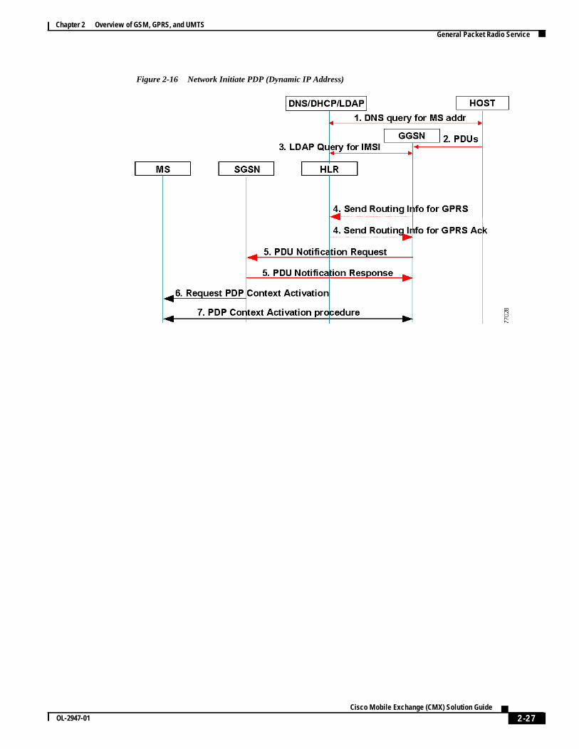
Network Initiated PDP Request For A Dynamic IP Address
The ETSI standards do not fully specify requirements for a network-generated PDP request wheclient is dynamically assigned a temporary IP by a DHCP server. The following message sequenCisco’s implementation for this scenario. This method uses Cisco’s Network Registrar (CNR), whincludes a DHCP, DNS, and an LDAP server.
1. The host initiates a DNS query to obtain the IP address of the MS from a DNS server. The Dserver resolves the client’s name to an IP address previously assigned to the client by the DHserver.
2. The host sends a request to the GGSN for a connection using this IP address.
3. The GGSN queries the LDAP server to obtain the MS IMSI. The LDAP server stores a recordthe MS with the client IMSI, name, and IP address.
4. The GGSN sends a PDU Notification Request message to the serving SGSN.
5. The SGSN sends a Request PDP Context Activation message to the MS and notifies it of the peconnection request.
6. If the MS agrees to accept the call, it enters the PDP Context Activation procedure with therequesting GGSN.
Figure 2-16describes a PDP request initiated from the network side when the client has been assa dynamic IP address. The numbers in the figure correspond to the numbered steps above.
2-26Cisco Mobile Exchange (CMX) Solution Guide
OL-2947-01
Chapter 2 Overview of GSM, GPRS, and UMTSGeneral Packet Radio Service
Figure 2-16 Network Initiate PDP (Dynamic IP Address)
2-27Cisco Mobile Exchange (CMX) Solution Guide
OL-2947-01

Chapter 2 Overview of GSM, GPRS, and UMTSUniversal Mobile Telecommunication System
obiles. It
s new, and
2G)
oint
ts for
ork
e.g.,
mobilecing and
Universal Mobile Telecommunication SystemThe Universal Mobile Telecommunication System (UMTS) is a third generation (3G) mobilecommunications system that provides a range of broadband services to the world of wireless and mcommunications. The UMTS delivers low-cost, mobile communications at data rates of up to 2 Mbppreserves the global roaming capability of second generation GSM/GPRS networks and provideenhanced capabilities. The UMTS is designed to deliver pictures, graphics, video communicationsother multimedia information, as well as voice and data, to mobile wireless subscribers.
The UMTS takes a phased approach toward an all-IP network by extending second generation (GSM/GPRS networks and using Wide-band Code Division Multiple Access (CDMA) technology.Handover capability between the UMTS and GSM is supported. The GPRS is the convergence pbetween the 2G technologies and the packet-switched domain of the 3G UMTS.
UMTS ServicesThe UMTS provides support for both voice and data services. The following data rates are targeUMTS:
• 144 kbps—Satellite and rural outdoor
• 384 kbps—Urban outdoor
• 2048 kbp—Indoor and low range outdoor
Data services provide different quality-of-service (QoS) parameters for data transfer. UMTS netwservices accommodate QoS classes for four types of traffic:
• Conversational class—Voice, video telephony, video gaming
• Streaming class—Multimedia, video on demand, webcast
• Interactive class—Web browsing, network gaming, database access
• Background class—E-mail, short message service (SMS), file downloading
The UMTS supports the following service categories and applications:
• Internet access—Messaging, video/music download, voice/video over IP, mobile commerce (banking, trading), travel and information services
• Intranet/extranet access—Enterprise application such as e-mail/messaging, travel assistance,sales, technical services, corporate database access, fleet/warehouse management, conferenvideo telephony
• Customized information/entertainment—Information (photo/video/music download), travelassistance, distance education, mobile messaging, gaming, voice portal services
• Multimedia messaging—SMS extensions for images, video, and music; unified messaging;document transfer
• Location-based services—Yellow pages, mobile commerce, navigational service, trading
2-28Cisco Mobile Exchange (CMX) Solution Guide
OL-2947-01

Chapter 2 Overview of GSM, GPRS, and UMTSUniversal Mobile Telecommunication System
tiontity
node
,heddata.
core
UMTS ArchitectureThe public land mobile network (PLMN) described in UMTS Rel. '99 incorporates three majorcategories of network elements:
• GSM phase 1/2 core network elements—Mobile services switching center (MSC), visitor locaregister (VLR), home location register (HLR), authentication center (AuC), and equipment idenregister (EIR)
• GPRS network elements—Serving GPRS support node (SGSN) and gateway GPRS support(GGSN)
• UMTS-specific network elements—User equipment (UE) and UMTS terrestrial radio accessnetwork (UTRAN) elements
The UMTS core network is based on the GSM/GPRS network topology. It provides the switchingrouting, transport, and database functions for user traffic. The core network contains circuit-switcelements such as the MSC, VLR, and gateway MSC (GMSC). It also contains the packet-switcheelements SGSN and GGSN. The EIR, HLR, and AuC support both circuit- and packet-switched d
The Asynchronous Transfer Mode (ATM) is the data transmission method used within the UMTSnetwork. ATM Adaptation Layer type 2 (AAL2) handles circuit-switched connections. Packetconnection protocol AAL5 is used for data delivery.
The UMTS architecture is shown inFigure 2-17.
Figure 2-17 UMTS Architecture
PSTN
GSM BSS
BTS
BTS
Node B
Node B
Node B
TRAU A
BSC
VLR
SGSN GGSN
GMSC
Abis MCS
EIR VLR HLR
AuC
lu PS
lur
lu CS
lu
RNC
Iub
Iub
Gb
Gn Gi
UTRAN
RNC
UE(USIM)
Uu
Um
Core network
ISDN
Externalnetworks
PDNe.g. internet,intranet, x.25
8107
4
2-29Cisco Mobile Exchange (CMX) Solution Guide
OL-2947-01

Chapter 2 Overview of GSM, GPRS, and UMTSUniversal Mobile Telecommunication System
to 3Gings limited byfore,
ode
are codelexcess
odeanltiple
er
istingde
General Packet Radio System
The General Packet Radio System (GPRS) facilitates the transition from phase1/2 GSM networksUMTS networks. The GPRS supplements GSM networks by enabling packet switching and allowdirect access to external packet data networks (PDNs). Data transmission rates above the 64 kbpof integrated services digital network (ISDN) are a requirement for the enhanced services supportUMTS networks. The GPRS optimizes the core network for the transition to higher data rates. Therethe GPRS is a prerequisite for the introduction of the UMTS.
UMTS Interfaces
The UMTS defines four new open interfaces (seeFigure 2-17):
• Uu interface—User equipment to Node B (the UMTS WCDMA air interface)
• Iu interface—RNC to GSM/GPRS (MSC/VLR or SGSN)
– Iu-CS—Interface for circuit-switched data
– Iu-PS—Interface for packet-switched data
• Iub interface—RNC to Node B interface
• Iur interface—RNC to RNC interface (no equivalent in GSM)
The Iu, Iub, andIur interfaces are based on the transmission principles of aynchronous transfer m(ATM).
UMTS Terrestrial Radio Access Network
The major difference between GSM/GPRS networks and UMTS networks is in the air interfacetransmission. Time division multiple access (TDMA) and freqency division multiple access (FDMA)used in GSM/GPRS networks. The air interface access method for UMTS networks is wide-banddivision multiple access (WCDMA), which has two basic modes of operation: frequency division dup(FDD) and time division duplex (TDD). This new air interface access method requires a new radio acnetwork (RAN) called the UTMS terrestrial RAN (UTRAN). The core network requires minormodifications to accommodate the UTRAN.
Two new network elements are introduced in the UTRAN: the radio network controller (RNC) and NB. The UTRAN contains multiple radio network systems (RNSs), and each RNS is controlled by RNC. The RNC connects to one or more Node B elements. Each Node B can provide service to mucells.
The RNC in UMTS networks provides functions equivalent to the base station controller (BSC)functions in GSM/GPRS networks. Node B in UMTS networks is equivalent to the base transceivstation (BTS) in GSM/GPRS networks. In this way, the UMTS extends existing GSM and GPRSnetworks, protecting the investment of mobile wireless operators. It enables new services over exinterfaces such asA, Gb, andAbis, and new interfaces that include the UTRAN interface between NoB and the RNC (Iub) and the UTRAN interface between two RNCs (Iur).
The network elements of the UTRAN are shown inFigure 2-18.
2-30Cisco Mobile Exchange (CMX) Solution Guide
OL-2947-01

Chapter 2 Overview of GSM, GPRS, and UMTSUniversal Mobile Telecommunication System
ollerents
mentS)
k. Inns.
ion
Figure 2-18 UTRAN Architecture
Radio Network Controller
The radio network controller (RNC) performs functions that are equivalent to the base station contr(BSC) functions in GSM/GPRS networks. The RNC provides centralized control of the Node B elemin its covering area. It handles protocol exchanges between UTRAN interfaces (Iu, Iur, andIub).Because the interfaces are ATM-based, the RNC performs switching of ATM cells between theinterfaces. Circuit-switched and packet-switched data from theIu-CS andIu-PS interfaces aremultiplexed together for transmission over the Iur, Iub, and Uu interfaces to and from the user equip(UE). The RNC provides centralized operation and maintenance of the radio network system (RNincluding access to an operations support system (OSS).
The RNC uses theIur interface. There is no equivalent to manage radio resources in GSM/GPRSnetworks. In GSM/GPRS networks, radio resource management is performed in the core networUMTS networks, this function is distributed to the RNC, freeing the core network for other functioA single serving RNC manages serving control functions such as connection to the UE, congestcontrol, and handover procedures. The functions of the RNC include:
• Radio resource control
• Admission control
• Channel allocation
• Power control settings
• Handover control
• Macro diversity
• Ciphering
• Segmentation and reassembly
• Broadcast signalling
• Open loop power control
Node B
Node B
UE
Node B
lur
lu
lu
Iub
MSC
SGSN
Iub
Iub
RNC
Core network
RNC
Uu
8107
5
2-31Cisco Mobile Exchange (CMX) Solution Guide
OL-2947-01

Chapter 2 Overview of GSM, GPRS, and UMTSUniversal Mobile Telecommunication System
de Btingo the
onng
hesing.
ower
MTShat
the
ntity
Node B
Node B is the radio transmission/reception unit for communication between radio cells. Each Nounit can provide service for one or more cells. A Node B unit can be physically located with an exisGSM base transceiver station (BTS) to reduce costs of UMTS implementation. Node B connects tuser equipment (UE) over theUu radio interface using wide-band code division multiple access(WCDMA). A single Node B unit can support both frequency division duplex (FDD) and time divisiduplex (TDD) modes. TheIub interface provides the connection between Node B and the RNC usiasynchronous transfer mode (ATM). Node B is the ATM termination point.
The main function of Node B is conversion of data on theUu radio interface. This function includes errorcorrection and rate adaptation on the air interface. Node B monitors the quality and strength of tconnection and calculates the frame error rate, transmitting this information to the RNC for procesThe functions of Node B include:
• Air interface transmission and reception
• Modulation and demodulation
• CDMA physical channel coding
• Micro diversity
• Error handling
• Closed loop power control
Node B also enables the UE to adjust its power using a technique called downlink transmission pcontrol. Predefined values for power control are derived from RNC power control parameters.
UMTS User Equipment
The UMTS user equipment (UE) is the combination of the subscriber’s mobile equipment and the Usubscriber identity module (USIM). Similar to the SIM in GSM/GPRS networks, the USIM is a card tinserts into the mobile equipment and identifies the subscriber to the core network.
The USIM card has the same physical characteristics as the GSM/GPRS SIM card and providesfollowing functions:
• Supports multiple user profiles on the USIM
• Updates USIM information over the air
• Provides security functions
• Provides user authentication
• Supports inclusion of payment methods
• Supports secure downloading of new applications
The UMTS standard places no restrictions on the functions that the UE can provide. Many of the idetypes for UE devices are taken directly from GSM specifications. These identity types include:
• International Mobile Subscriber Identity (IMSI)
• Temporary Mobile Subscriber Identity (TMSI)
• Packet Temporary Mobile Subscriber Identity (P-TMSI)
• Temporary Logical Link Identity (TLLI)
• Mobile station ISDN (MSISDN)
• International Mobile Station Equipment Identity (IMEI)
2-32Cisco Mobile Exchange (CMX) Solution Guide
OL-2947-01

Chapter 2 Overview of GSM, GPRS, and UMTSUniversal Mobile Telecommunication System
)
like
• International Mobile Station Equipment Identity and Software Number (IMEISV)
The UMTS UE can operate in one of three modes of operation:
• PS/CS mode—The UE is attached to both the packet-switched (PS) and circuit-switched (CSdomain, and the UE can simultaneously use PS and CS services.
• PS mode—The MS is attached to the PS domain and uses only PS services (but allows CS-services such as voice over IP [VoIP]).
• CS mode—The MS is attached to the CS domain and uses only CS services.
2-33Cisco Mobile Exchange (CMX) Solution Guide
OL-2947-01

Chapter 2 Overview of GSM, GPRS, and UMTSUniversal Mobile Telecommunication System
2-34Cisco Mobile Exchange (CMX) Solution Guide
OL-2947-01