orthogonal frequency division multiplexing for high-speed optical transmission
TRANSCRIPT

Orthogonal frequency division multiplexing for high-speed optical transmission
Ivan B. Djordjevic and Bane Vasic University of Arizona, Department of Electrical and Computer Engineering, Tucson, AZ 85721, USA
[email protected], [email protected]
Abstract: Optical Orthogonal frequency division multiplexing (OOFDM) is shown to outperform RZ-OOK transmission in high-speed optical communications systems in terms of transmission distance and spectral efficiency. The OOFDM in combination with the subcarrier multiplexing offers a significant improvement in spectral efficiency of at least 2.9 bits/s/Hz.
©2006 Optical Society of America
OCIS codes: (060.4510) Optical communications; (060.2310) Fiber optics; (060.4080) Modulation; (060.4230) Multiplexing; (999.9999) Orthogonal frequency division multiplexing; (999.9999) LDPC codes
References and Links 1. R. R. Mosier, and R. G. Clabaugh, “Kineplex, a bandwidth efficient binary transmission system,” AIEE
Trans. 76, 723-728 (1958). 2. R. W. Chang, “Orthogonal frequency division multiplexing,” U.S. Patent 3 488 445, 1970. 3. R. Van Nee, and R. Prasad, OFDM Wireless Multimedia Communications (Artech House, Boston, 2000). 4. R. Prasad, OFDM for Wireless Communications Systems (Artech House, Boston, 2004). 5. L. M. Cimini, Jr., “Analysis and simulation of a digital mobile channel using orthogonal frequency division
multiplexing,” IEEE Trans. Comm. COM-33, 665-675(1985). 6. Y. Sun, “Bandwidth-efficient wireless OFDM,” IEEE Selected Areas Comm. 19, 2267 – 2278 (2001). 7. T. Wang, J. G. Proakis, and J. R. Zeidler, “Techniques for suppression of intercarrier interference in OFDM
systems,” in Proc. 2005 IEEE Wireless Communications and Networking Conference, pp. 39-44 (2005). 8. Y. Wu and B. Caron, “Digital television terrestrial broadcasting,” IEEE Commun. Mag., 46–52 (1994). 9. Q. Pan, and R. J. Green, “Bit-error-rate performance of lightwave hybrid AM/OFDM systems with
comparison with AM/QAM systems in the presence of clipping impulse noise,” IEEE Photon. Technol. Lett. 8, 278–280 (1996).
10. A. Kim, Y.Hun Joo, and Y. Kim, “60 GHz wireless communication systems with radio-over-fiber links for indoor wireless LANs,” IEEE Trans. Consum. Electron. 50, 517-520 (2004).
11. B. J. Dixon, R.D. Pollard, and S. Iezekiel, ”Orthogonal frequency-division multiplexing in wireless communication systems with multimode fiber feeds,” IEEE Trans. Microwave Theory and Techniques 49, 1404 – 1409 (2001).
12. I. B. Djordjevic, O. Milenkovic, and B. Vasic, “Generalized Low-Density Parity-Check Codes for Optical Communication Systems,” IEEE/OSA J. Lightwave Technol. 23, 1939- 1946 (2005).
13. T. Mizuochi, Y. Miyata, T. Kobayashi, K. Ouchi, K. Kuno, K. Kubo, K. Shimizu, H. Tagami, H. Yoshida, H. Fujita, M. Akita, and K. Motoshima, “Forward error correction based on block turbo code with 3-bit soft decision for 10 Gb/s optical communication systems,” IEEE J. Selected Topics Quant. Electron. 10, 376-386 (2004).
14. R. Hui, B. Zhu, R. Huang, C. T. Allen, K. R. Demarest, and D. Richards, “Subcarrier multiplexing for high-speed optical transmission,” IEEE/OSA J. Lightwave Technology 20, 417-427 (2002).
15. M. Sandell J. J. van de Beek, and P. O. Börjesson, “Timing and frequency synchronization in OFDM systems using cyclic prefix,” in Proc. Int. Symp. Synchron., Saalbau, Essen, Germany, pp. 16-19, 1995.
16. R. Böhnke, and T. Dölle, “Preamble structures for HiperLAN type 2 system,” ETSI BRAN Doc. No. HL13SON1A, Apr. 7, 1999.
17. T. M. Schmidl, and D. C. Cox, “Robust frequency and timing synchronization for OFDM,” IEEE Trans. Comm. 45, 1613-1621 (1997).
18. M. Morelli, and U. Mengali, “A comparison of pilot-aided channel estimation methods for OFDM systems,” IEEE Trans. Signal Process. 49, 3065-3073 (2001).
19. A. G. Armada, “Understanding the effects of phase noise in orthogonal frequency division multiplexing (OFDM),” IEEE Trans. Broadcasting 47, 153-159 (2001).
20. J. P. Gordon, and L. F. Mollenauer, “Phase noise in photonic communication systems using linear amplifiers,” Opt. Lett. 15, 1351-1353 (1990).
(C) 2006 OSA 1 May 2006 / Vol. 14, No. 9 / OPTICS EXPRESS 3767#10177 - $15.00 USD Received 3 January 2006; revised 11 April 2006; accepted 15 April 2006

21. B. Vasic, I. B. Djordjevic, and R. Kostuk, “Low-density parity check codes and iterative decoding for long haul optical communication systems,” IEEE/OSA J. Lightwave Technol. 21, 438-446 (2003).
22. A. J. Lowery, L. Du, and J. Armstrong, "Orthogonal frequency division multiplexing for adaptive dispersion compensation in long haul WDM systems" in Proc. OFC Postdeadline Papers, Paper no. PDP39, 2006.
1. Introduction
In order to exploit optical bandwidth more efficiently, novel transmission technologies are intensively studied. High-speed optical transmission systems are impaired by interchannel and intrachannel nonlinearities, polarization mode dispersion and chromatic dispersion, and require precise dispersion compensation techniques. To increase the transmission capacity, narrower channel spacing is pursued and novel modulation formats are investigated. Orthogonal frequency division multiplexing (OFDM) [1-8] is a special case of multicarrier transmission in which a single information-bearing stream is transmitted over many lower rate sub-channels. It has been used for digital audio broadcasting [3], HDTV terrestrial broadcasting [8], in HDSL, ADSL and VDSL [3,4], IEEE 802.11, HIPERLAN/2 and MMAC wireless LANs [3], and has been studied for the application in lightwave hybrid AM/OFDM cable systems [9], and in radio over fiber-based networks [10,11]. OFDM offers good spectral efficiency and efficient elimination of subchannel and symbol interference using the fast Fourier transform (FFT) for modulation and demodulation, which does not require any equalization. The above features as well as its high immunity to dispersion and burst-errors makes OFDM an intriguing candidate for long-haul optical transmission. Surprisingly, there is no published work, at the time of submission, on the use of OFDM in long-haul optical transmission. In this paper we propose an optical OFDM (OOFDM) system built of standard optical and RF components. The key idea behind OOFDM is to split a high-data rate data-stream into a number of low-rate data-streams that are transmitted simultaneously over a number of subcarriers. The symbol duration of these low-rate data-streams is made substantially larger, with a goal to increase the immunity of a system to residual chromatic dispersion. On the other hand, OFDM is more sensitive to phase noise, and has a relatively large peak-to-average power ratio [3,4], which might result in higher sensitivity to fiber nonlinearities; so to fully exploit advantages and minimize side effects of OFDM, a careful design of a system is needed. The paper is organized as follows. The concept of OOFDM high-speed transmission is introduced in Section 2, simulation results are presented in Section 3, and conclusions are given in Section 4.
2. Optical OFDM High-Speed Transmission
One of the main reasons for suitability of the OOFDM for long-haul transmission is its ability to deal with large pulse spreads due to chromatic dispersion. As it will be shown in Section 3, almost all operations (except for those performed in a Mach-Zhender modulator (MZM), a distributed feedback laser (DFB) and a photodetector (PD)) are performed in the RF domain. This is advantageous because microwave devices are much more mature than their optical counterparts and because the frequency selectivity of microwave filters and the frequency stability of microwave oscillators are significantly better than that of corresponding optical devices. Furthermore, the phase noise levels of microwave oscillators is much lower than that of DFBs, suggesting that RF coherent detection is easier to implement than optical coherent detection. This, in turn, allows a system architect to apply directly the most advanced modulation formats already developed for wireless RF communications. The basic OOFDM transmitter and receiver configurations are given in Fig. 1(a) and 1(b) respectively. A serial-to-parallel converter (DEMUX) parses the information sequence into blocks of B bits. The B bits in each block (frame) are subdivided into K subgroups with the ith subgroup containing bi bits, B=∑bi. The bi bits from the ith subgroup are mapped into a complex-valued signal point from a 2bi-point signal constellation such is, e.g., QAM, which is
(C) 2006 OSA 1 May 2006 / Vol. 14, No. 9 / OPTICS EXPRESS 3768#10177 - $15.00 USD Received 3 January 2006; revised 11 April 2006; accepted 15 April 2006

considered in this paper. The complex-valued signal points from all K subchannels are considered as the values of the discrete Fourier transform (DFT) of a multicarrier OFDM signal. Therefore, the symbol interval length in an OFDM system is T=KTs, where Ts is the symbol-interval length in a single-carrier system. By selecting K, the number of subchannels, sufficiently large, the OFDM symbol interval can be made much larger than the dispersed pulse-width in a single-carrier system, resulting in an arbitrary small intersymbol interference.
Binary input DEMUX
Constellation mapper… IFFT
Parallel-to-serialconverter
D/Aconverter
RFupconverter
MZM
DFB
to fiber… …Binary
input DEMUXConstellation
mapper… IFFTParallel-to-serial
converterD/A
converterRF
upconverterMZM
DFB
to fiber… …
(a)
PDfrom fiber
RFdownconverter
Carrier suppression
andA/D converter
FFT DemapperEstimate of the
original datainput
MUXSerial-to-parallel
converter … …PDfrom fiber
RFdownconverter
Carrier suppression
andA/D converter
FFT DemapperEstimate of the
original datainput
MUXSerial-to-parallel
converter … …
(b)
Original NFFT samples
Suffix
Preffix
NG /2 samplesNG /2 samples
OFDM symbol after cyclic extension, NFFT + NG samples
Original NFFT samples
Suffix
Preffix
NG /2 samplesNG /2 samples
OFDM symbol after cyclic extension, NFFT + NG samples
(c)
TFFT Tguard/2Tguard/2
Twin
Effective part
T=TFFT+Tguard+Twin
OFDM symbol duration
kT
TFFT Tguard/2Tguard/2
Twin
Effective part
T=TFFT+Tguard+Twin
OFDM symbol duration
kT (d)
Fig. 1. Transmitter (a) and receiver (b) configurations, (c) OFDM symbol cyclic extension, (d) OFDM symbol after windowing
The transmitted OFDM signal can be written as [4]
( ) ( )( )2
/ 2 1FFT,
/ 2FFT
FFTguard win guard win
,
/ 2 / 2
ij t kT
N TFFTi k
k i Ns t w t kT X e
kT T T t kT T T T
π ⋅ −−∞
=−∞ =−= − ⋅∑ ∑
− − ≤ ≤ + + +
(1)
(C) 2006 OSA 1 May 2006 / Vol. 14, No. 9 / OPTICS EXPRESS 3769#10177 - $15.00 USD Received 3 January 2006; revised 11 April 2006; accepted 15 April 2006

where Xi,k is the i-th subcarrier of k-th OFDM symbol, T is the OFDM symbol duration, TFFT is the OFDM symbol effective part, Tguard is the guard interval (the duration of cyclic extension), Twin is the length of the windowing interval, and w(t) is the window function. The OFDM symbol, shown in Figs. 1(c)-(d), is therefore generated as follows: NQAM input QAM symbols are zero-padded to obtain NFFT input samples for IFFT, the Ngurad samples are inserted to create the guard interval Tguard, and the OFDM symbol is multiplied by the window function (raised cosine function is used in [3]-[4], however the Kaiser, Blackman-Harris and other window functions are also applicable). After the appropriate sampling, the summation term in (1),
/ 2 1FFTFFT, ,
FFT/ 2FFT
exp 2 , 0,1,.., 1,N
m k i ki N
imx X j m N
Nπ
−
=−
⎛ ⎞= = −∑ ⎜ ⎟⎝ ⎠
corresponds to the DFT (except from the normalization factor 1/N). Therefore, the modulator and demodulator can be implemented by use of the FFT algorithm to calculate inverse and direct DFT. The purpose of cyclic extension is to preserve the orthogonality among subcarriers even when the neighboring OFDM symbols partially overlap due to dispersion, and the purpose of the windowing is to reduce the out-of band spectrum. The cyclic extension, illustrated in Fig. 1 (c), is done by repeating the last Nguard/2 samples of the effective OFDM symbol part (of duration TFFT with NFFT samples) as the prefix, and repeating the first Nguard/2 samples (out of NFFT) as the suffix. (Notice that windowing is more effective for smaller numbers of subccarriers.) After a D/A conversion and RF up-coversion, the OFDM signal is driven to the MZM and then transmitted over the fiber. The DC component is inserted to be able to recover the QAM symbols incoherently. It is assumed that 50% is allocated for the transmission of carrier, for the reasons given in [14]. At the receiver side, after the photodetection, RF down-conversion and carrier suppression, the received signal is demodulated by computing the DFT. For demonstration purposes the power spectral densities at different points are given in Figs. 2(a) and 2(c) for double-sideband (DSB) transmission, and in Fig. 2(d) for single-sideband (SSB) transmission. The in-phase component of RF signal after up-conversion is given in Fig. 2(b), and shows that MZM operates in quasi-linear regime for Vπ voltages above 6 V. The OFDM signal bandwidth is set to 10 GHz, the number of subchannels is set to 256, FFT/IFFT is calculated in 8192 points, the bandwidth of optical filter is set to 60 GHz, the total averaged launched power is set to 0 dBm. No windowing or clipping is applied. From (1) is obvious that sub-carriers are orthogonal to each-other (each subcarrier contains an integer number of cycles of duration T), suggesting that OFDM is an efficient way for increasing the spectral efficiency, because the partial overlapping between neighboring sub-carriers is allowed. The spectral efficiency of a WDM system can be also improved by combining the OFDM channels using the subcarrier multiplexing [14]. To illustrate the idea, the power spectral density of four subcarrier-multiplexed OFDM channels is given in Fig. 2(e). If a 16-QAM is used in combination with a 38.75 Mb/s sub-channels, the OOFDM system proposed here allows transmitting a 40 Gb/s signal over a 10 GHz bandwidth, increasing therefore the spectral efficiency of an RZ-OOK scheme significantly. Another way of transmitting a 40 Gb/s signal over a 10 GHz bandwidth is to use BPSK provided that data rate per sub-carrier is 155 Mb/s. The spectral efficiency, of the SCM scheme whose PSD is given in Fig. 2(e) is 4×40 Gb/s/55 GHz=2.9 bits/s/Hz, which is significantly better than that of an RZ-OOK scheme. The BER performance of the proposed OFDM scheme against conventional OOK scheme is given in Fig. 3 for the linear channel model. Because the OFDM is essentially an RF coherent scheme, it provides initial 3 dB improvement compared to OOK. However, if the comparison is done for the same average launched powers (to keep the level of nonlinearities comparable), than the 3 dB initial advantage is lost, because the 50% of the total launched power is allocated for the transmission of a carrier. Moreover, for the same launched powers (into fiber) the energy per bit for RZ-OOK is significantly larger than that of OFDM.
(C) 2006 OSA 1 May 2006 / Vol. 14, No. 9 / OPTICS EXPRESS 3770#10177 - $15.00 USD Received 3 January 2006; revised 11 April 2006; accepted 15 April 2006

-100 -80 -60 -40 -20 0 20 40 60 80 100
-80
-70
-60
-50
-40
-30
-20
-10
0
Pow
er s
pect
ral d
ensi
ty, P
SD [
dBm
/Hz]
Frequency (relative to optical carrier), f [GHz]
MZM output PSD
(a)
0 500 1000 1500 2000 2500 3000 3500 4000
-1.2
-0.8
-0.4
0.0
0.4
0.8
1.2In
-pha
se R
F u
pcon
vert
er c
ompo
nent
, vR
F [V
]
Time, t [ps] (b)
-100 -80 -60 -40 -20 0 20 40 60 80 100-100
-90
-80
-70
-60
-50
-40
-30
-20
Pow
er s
pect
ral d
ensi
ty, P
SD [
dBm
/Hz]
Frequency (relative to optical carrier), f [GHz]
PD output PSD
(c)
-100 -80 -60 -40 -20 0 20 40 60 80 100-80
-70
-60
-50
-40
-30
-20
-10
0
Pow
er s
pect
ral d
ensi
ty, P
SD [
dBm
/Hz]
Frequency (relative to optical carrier), f [GHz]
SSB PSD
(d)
-100 -80 -60 -40 -20 0 20 40 60 80 100-70
-60
-50
-40
-30
-20
-10
0
10
Pow
er s
pect
ral d
ensi
ty, P
SD [
dBm
/Hz]
Frequency, f [GHz]
MZ modulator, SSB
(e)
Fig. 2. Power spectral densities (a), (c)-(d), MZM input waveform (b), and PSD of 4 subcarrier-multiplexed OFDM channels (e).
(C) 2006 OSA 1 May 2006 / Vol. 14, No. 9 / OPTICS EXPRESS 3771#10177 - $15.00 USD Received 3 January 2006; revised 11 April 2006; accepted 15 April 2006

However, this is the only way to keep fiber nonlinearities reasonable low, and to allow
MZM and RF amplifier to operate in quasi-linear regime. The comparison is done in electrical domain, because the concept of optical signal-to-noise ratio is not applicable to the OFDM waveforms (shown in Fig. 2(b)). In simulations, a lattice LDPC(8547,6919,0.81) code of girth-8 and column weight 5 is employed as an FEC scheme (see [21] for more details on code design). The QPSK OOFDM combined with LDPC coding provides the coding gain improvement of more than 2 dB over LDPC coded RZ-OOK at BER of 10-8, and at the same time allows transmitting a 40 Gb/s signal over a 10 GHz bandwidth.
2 4 6 8 10 12 141x10-8
1x10⁻⁷
1x10⁻⁶
1x10⁻⁵
1x10⁻⁴
1x10⁻³
1x10⁻²
1x10⁻¹
Bit
-err
or r
ate,
BE
R
Eb/N
o [dB] (per information bit)
OFDM (linear case, Fig. 1): Uncoded, M = 4 Uncoded, M = 16 LDPC(8547,6919,0.81), M = 4 LDPC(8547,6919,0.81), M = 16
OOK (AWGN): Uncoded LDPC(8547,6919,0.81)
Fig. 3. BER performance of OFDM against OOK for a linear channel model
3. Simulation Results
The results of simulation in the presence of Kerr nonlinearities and ASE noise are given in Figs. 5-6, for dispersion maps from Fig. 4. The fiber parameters are given in Table 1. The dispersion map I (Fig. 4(a)) is composed of N spans of length L=120 km, consisting of 2L/3 km of D+ fiber followed by L/3 km of D- fiber, with pre-compensation of –320 ps/nm and corresponding post-compensation. The dispersion map II (Fig. 4(b)) is similar to dispersion map I, in which the sections of D+ and D- fibers are replaced with conventional SMF and DCF, respectively. The SMF and DCF lengths in a span (of the dispersion map II) are 101.9 km and 18.1 km, respectively, and the pre- and post-compensation sections lengths are set to 3.34 and 18.75 km respectively. In simulations, two different OFDM schemes are considered. In both schemes the signal bandwidth is set to 10 GHz, while the number of subchannels is set to either 256 or 64, and FFT/IFFT is calculated in either 8192 or 1024 points. In the first scheme (with 256 subchannels) no windowing or clipping is applied, while the second scheme (with 64 subchannels) uses the windowing based on Blackman-Harris windowing function. To reduce the peak-to-average ratio, the peak windowing [3] based on Hann windowing function is applied. In both schemes the bandwidth of optical filter is set to 60 GHz, the total averaged launched power is set to 0 dBm, and the RF carrier frequency is set to 25 GHz. 16-QAM, 4-QAM (QPSK) and 2-QAM (BPSK) are observed. The de-mapper is based on a Euclidean distance receiver. For regular dispersion maps (map I and map II), Fig. 6, only the M=2 case is able to outperform RZ-OOK (of duty cycle 33%) operating at 40 Gb/s. The OOFDM system and RZ-OOK are compared with respect to the BER rather than Q-factor, because the Q-factor is not a good figure of merit when the fiber nonlinearities are important. The influence of Kerr nonlinearities is illustrated in Figs. 5(b)-(c), where the received signal constellation is shown after 15 spans of dispersion map II for M=4. The phase noise introduced by the self-phase modulation (SPM) causes the rotation of the constellation
(C) 2006 OSA 1 May 2006 / Vol. 14, No. 9 / OPTICS EXPRESS 3772#10177 - $15.00 USD Received 3 January 2006; revised 11 April 2006; accepted 15 April 2006

diagram, and this effect is known as the common phase error [19]. By using the phase correction based on pilot tones, the phase rotation due to SPM can be completely eliminated, improving the BER performance. For the phase correction [19] in Fig. 5 (c) four pilots (out of 64 subchannels) are employed. The phase noise present in RF up- and down-converters, the laser phase noise and the phase noise due to the Gordon-Mollenauer effect [20] (the conversion of intensity fluctuations from ASE noise trough the Kerr nonlinearity to phase fluctuations) cause the inter-carrier interference and can only be partially cancelled by the phase correction based on pilot tones. The residual carrier offset, which is constant for the duration of OFDM symbol but changes randomly from symbol to symbol, and comes from the PLL used in RF down-conversion, can be cancelled using the cyclic extension [15,16] as shown in Fig. 7. Some alternative approaches include the application of special training sequences [17,18], and the pilot-aided channel estimation [18], however, these approaches are more challenging to implement at high-speed. The frequency offset correction scheme can also be used for synchronization. From Fig. 1(c) is obvious that the prefix and the first Nguard/2 samples of the effective OFDM symbol part are identical to the last Nguard/2 samples of the effective OFDM symbol part and the suffix, spaced TFFT seconds apart. By calculating the autocorrelation of these two parts we are able to estimate the frequency offset and remove it (see Fig. 7). At the same time correlation peaks obtained after every OFDM symbol can be used for timing as explained in [15]. The results of simulations from Figs. 5-6 are obtained for a zero residual dispersion, because the aim of the paper is to show that carefully designed OOFDM system outperforms the RZ-OOK even in the presence of nonlinearities (see Fig. 6), and increases the spectral efficiency. To deal with residual dispersion the method based on pilot tones can be employed, as suggested in [22].
Transmitter Receiver
N spans
EDFA
D+ D-D- D+
EDFAEDFA EDFA
Transmitter Receiver
N spans
EDFA
D+ D-D- D+
EDFAEDFA EDFA
(a)
Transmitter Receiver
N spans
EDFA
SMF DCFDCF SMF
EDFAEDFA EDFA
Transmitter Receiver
N spans
EDFA
SMF DCFDCF SMF
EDFAEDFA EDFA
(b) Fig. 4. Dispersion maps under consideration.
Table 1. Fiber parameters
D+ FIBER D- FIBER SMF DCF
Dispersion [ps/(nm km)] 20 -40 16 -90
Dispersion Slope [ps/(nm2 km)] 0.06 -0.12 0.08 -0.45
Effective Cross-sectional Area [μm2] 110 50 80 30
Nonlinear refractive index [m2/W] 2.6⋅10-20 2.6⋅10-20 2.6⋅10-20 2.6⋅10-20
Attenuation Coefficient [dB/km] 0.19 0.25 0.22 0.5
(C) 2006 OSA 1 May 2006 / Vol. 14, No. 9 / OPTICS EXPRESS 3773#10177 - $15.00 USD Received 3 January 2006; revised 11 April 2006; accepted 15 April 2006
-2 -1 0 1 2
-2
-1
0
1
2
Real axis Im
agi
nar
y a
xis
(a)
-3 -2 -1 0 1 2 3-3
-2
-1
0
1
2
3
Real axis
Ima
gina
ry a
xis
(b)
-3 -2 -1 0 1 2 3-3
-2
-1
0
1
2
3
Real axis
Ima
gin
ary
axi
s
(c)
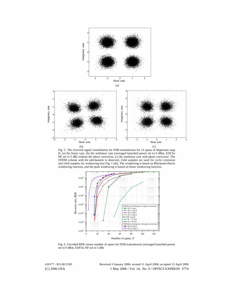
Fig. 5. The received signal constellation for DSB transmission for 15 spans of dispersion map II: (a) the linear case, (b) the nonlinear case (averaged launched power set to 0 dBm, EDFAs NF set to 5 dB) without the phase correction, (c) the nonlinear case with phase correction. The OFDM scheme with 64 subchannels is observed, 2x64 samples are used for cyclic extension and 2x64 samples for windowing (see Fig. 1 (d)). The windowing is based on Blackamn-Harris windowing function, and the peak windowing is based on Hann windowing function.
0 20 40 60 80 100 1201x10-7
1x10⁻⁶
1x10⁻⁵
1x10⁻⁴
1x10⁻³
1x10⁻²
1x10⁻¹
Bit-
erro
r ra
te, B
ER
Number of spans, N
OFDM (256 subchannels, no phase correction): M=2, map I M=2, map II M=4, map I M=4, map II
RZ-OOK, map II: R
b = 10 Gb/s
Rb = 40 Gb/s
OFDM (64 subchannels, with phase correction): M=4, map II M=16, map II
Fig. 6. Uncoded BER versus number of spans for DSB transmission (averaged launched power set to 0 dBm, EDFAs NF set to 5 dB)
(C) 2006 OSA 1 May 2006 / Vol. 14, No. 9 / OPTICS EXPRESS 3774#10177 - $15.00 USD Received 3 January 2006; revised 11 April 2006; accepted 15 April 2006

TFFT delay Conjugation
Integrator(over Tguard)
Maximum correlation
Frequency offset
OFDM signal
Timing
TFFT delay Conjugation
Integrator(over Tguard)
Maximum correlation
Frequency offset
OFDM signal
Timing
Fig. 7. Frequency offset correction and timing using the cyclic prefix
4. Conclusion
We proposed the OOFDM, a novel modulation format for long-haul transmission systems, which provides a number of advantages: (i) increasing of the transmission distance, (ii) improvement of the spectral efficiency, and (iii) simplification of the dispersion compensation engineering. To further improve spectral efficiency to at least 2.9 bits/s/Hz, the OOFDM SSB transmission should be combined with subcarrier multiplexing.
With a de-mapper designed by taking the statistics of the channel into account, the transmission distance and the spectral efficiency can be further improved. In regular dispersion maps (see Fig. 4) 16-QAM OOFDM can be used in short reach systems, QPSK OFDM in long reach systems if LDPC coding is not applied and in long-haul systems if LDPC coding is applied. BPSK OOFDM can be used as an alternative to 40 Gb/s RZ-OOK. From Fig. 6 it can be seen that for the BER threshold of 10-2, which is a sufficient level for advanced FEC (see [12-13]), the BPSK OFDM impoves transmission distance of a 40 Gb/s RZ-OOK by around 1200 km. The OOFDM system with 64 subchannels performs worse compared with OOFDM system with 256 subchannels even when phase-correction and peak windowing are applied (see Fig. 6).
Acknowledgments
This work is funded in part by the NSF under Grant ITR 0325979 and Grant CCR 0208597.
(C) 2006 OSA 1 May 2006 / Vol. 14, No. 9 / OPTICS EXPRESS 3775#10177 - $15.00 USD Received 3 January 2006; revised 11 April 2006; accepted 15 April 2006