ornl tm 6413
DESCRIPTION
http://www.energyfromthorium.com/pdf/ORNL-TM-6413.pdfTRANSCRIPT

&I Y O 6 ORNLlTM-6413
R
Molten-Salt Reactors for Efficient Nuclear Fuel Utilization Without
Plutonium Separation
J. R. Engel W. R. Grimes W. A. Rhoades J. F. Dearing

,
Printed in the United States of America. Available from National Technical Information Service
U.S. Department of Commerce 5285 Port Royal Road, Springfield, Virginia 22161
Price: Printed Copy $5.25; Microfiche $3.00
This report was prepared as an account of work sponsored by an agency of theunited States Government. NeithertheUnited StatesGovemment norany agency thereof, nor any of their employees, contractors, subcontractors, or their employees, makes any warranty, express or implied, nor assumes any legal liability or responsibility for any third party’s use or the results of such use of any information, apparatus, product or process disclosed in this report, nor represents that its use by such third party would notsinfringe privately owned rights.
ORNL/TM-6413 Dist. Category UC-76
Contract No. W-7405-eng-26
Engineering Technology Division
MOLTEN-SALT REACTORS FOR EFFICIENT NUCLEAR FUEL UTILIZATION WITHOUT PLUTONIUM SEPARATION
J. R. Engel W. A . Rhoades W. R. Grimes J. F. Dearing
i
Date Published - August 1978
NOTICE: This document contains information of a preliminary nature and was prepared primarily for internal use at the Oak Ridge National Laboratory.
I united sate1 mu me United suto Lk+mIlmt d pow, WT w dmei e l n p b w . nor My of mer Prepared by the mntnctm. wbamh.ccon. a tbrk employer. nnlp,
w W M t y . gxmir o( Implied. u PY krrl OAK RIDGE NATIONAL LABORATORY liability a r a p s i b l t y for the -cy. crmplctenar
pmr dicdad.u -nn (h.1 m me would not Mrmle printcly a m d @a.
Oak Ridge, Tennessee 37830 operated by
UNION CARBIDE CORPORATION for the
DEPARTMENT OF ENERGY

. . ,
i
i
iii
CONTENTS Page
r
SUMMARY .......................................................... v ABSTRACT ........................................................ 1
INTRODUCTION .................................................... 1
BACKGROUND ...................................................... 3 HIGH-ENRICHMENT MSRS ............................................ 5
ORNL Reference Design MSBR .................................... 5
.
Reference Design Variations .................................. 11 Plutonium Transmuter for 3U Production ..................... 13
DENATURED MSR ................................................... 14 General Characteristics ...................................... 14 Reactor Characteristics ...................................... 16 Core Thermal Hydraulics ...................................... 31 Chemical Processing ........................................... 33 Balance of Plant ............................................. 39
MSR TECHNOLOGY STATUS ........................................... 39 z \ REFERENCES ...................................................... 40 -
i

I j . . . . . . ~
. . . . . , . . ~ . ~ . ~ " .
. _ I . , . . . . . . ,
. . - " i r _ - _ . . . . - . ( . . '
. . . < . . ^ . . , . . . . . . . . . . . . . . . . .
, . " '~ - . . . 1 . - . . , . .
. . . . . . . . . . , . - ,
. . , , I ,
. . i l . . < . 1 , . . . ,
. . . . . . . . & :
. I i . ~ - . ~ ' .
. . , .~ ~ .. . . . . . , .
. . . . . .

V t
. e
SUMMARY
Research and development studies of moltcn-salt reactors (MSRs) for special purposes have been under way since 1947 and for possible applica- tion as possible commercial nuclear electric power generators since 1956. For the latter, the previous emphasis has been on breeding performance and low fissile inventory to help limit the demand on nonrenewable natural re- sources (uranium) in an expanding nuclear economy; little or no thought has been given to alternative uses of nuclear fuels such as proliferation of nuclear explosives. As a consequence, the conceptual designs that evolved (e.g. , the ORNL reference design MSBR) all favored enriched 33U
as fuel with an on-site chemical processing facility from which portions of that fuel could be diverted fairly easily. With the current interest in limiting the proliferation potential of nuclear electric power systems, a redirected study of MSRs was undertaken in an effort to identify concep- tual systems that would be attractive in this situation. practical proliferation-resistant MSRs could be designed and built, and this report describes a particularly attractive break-even breeder that includes an on-site chemical reprocessing facility within the reactor pri- mary containment.
It appears that
The point of departure for this study (as for other recent MSR studies) was the ORNL reference design MSBR, which in many respects, reflects the state of MSR technology at the end of the reactor development program in fiscal year 1976. This reactor was characterized by a moderate breeding ratio (%1.07), a low specific inventory of fissile fuel rQI.5 kg/ MW(e)], a reasonable fuel doubling time (%2O-years), and almost no plu- tonium from the fuel cycle. s to be achieved through the use of fuel highly enriched in 233U and 235U (%72%) in a high-power- density core and an-on-site fission-product-cleanup system with a 10-day
fuel processin Two important steps in this processing cycle were (1) the isolarion’of the enriched uranium from, and its subsequent return to, the fuel salt and (2) the isolation of 233Pa for decay to 233U outside
This performance
ycle.
the reactor,neutron flux to prevent counterproductive neutron captures in

Vi 8
the protactinium at the high flux.levels* in the reactor. Both of these
steps, along with the ready availability of excess bred fuel, were perceived
-'to contribute to the proliferation sensitivity of the reference concept.
A preliminary study was undertakenlate in calendar year 1976 to see
if the referenceMSBR concept could be modified to significantly enhance ' its proliferation resistance. Among the modifications considered-were
elimination of the breeding gain, a reduction intpower density (and spe- cific power) so 'that protactinium isolation could,be avoided without ex-
i cessive penalties, and.several:conceptual variations,in the fuel processing cycle. Reduction of the fiseile-uranium enrichment (i.e., denaturing) was not considered at that time because of.perceived problems with the -attendant plutonium production. The net conclusion.of. this study was :
that, while some enhanded proliferation resistance could be achieved,‘;. : the reference MSBRconcept probably could not be made. sufficiently re-
sistant to allow its deployment outside areas that would be "secure" against diversion of fissile material or proliferation.
In a minor extension of the above 'study it was shown that, if MSRs were confined to "secure".areas, they could also be used to produce power
from fission of plutonium (generated'by other reactors) and to convert thorium to 233U for subsequent denaturing and use at dispersed sites.
Since.the confinement of MSRs exclusively to "secure" sites did not ap- pear to be desirable, no further consideration was .given to concepts
without denatured uranium. The current study of proliferation-resistant systems is based on the
premise that MSRs would be attractive for dispersed deployment if they could operate with denatured uranium fuel, have good .resource utilization
,characteristics, and require no fuel reprocessing outside the reactor ,~ primary containment envelope. A number of molten-salt concepts may meet these requirements, but the one that currently appears most attractive,
is a system with denatured fuel and a net effective lifetime breeding ratio of .l.OO f This implies that, once such a reactor were supplied with
1.:. :
..*Not related to proliferation, but a.potential technical problem, was the fact that portions of the moderator graphite in the MSBR core would have to be replaced every four years because of neutron radiation damage at the projected high flux levels.
.
.

vii
t
c
a fissile fuel charge, it and succeeding generations of hardwa,re could operate indefinitely with no further addition of fissile material. tions and removals of fertile material - both salt constituents would, however, be required to maintain a stable chemical composition.
Addi- and 232Th - and other
Break-even breeding in a denatured MSR is achieved by making several changes in the reference design MSBR concept,
the reactor core size andAsalt-graphite configuration to lower the core power density and to enhance neutron resonance self-shielding in the in the fuel. (to about 2.4 kg fissile uranium plus 0.16 kg fissile plutonium per electric megawatt), but they also reduced the neutron losses to fission products and 233Pa and captures in 238U to help compensate for the reduced breeding performance imposed by the presence of the 238U denaturant. the lower neutron flux associated with these changes would extend the life expectancy of the moderator graphite in the core to approximately that of the reactor plant, thereby obviating the need for periodic graphite re- placement. and allow for simpler geometric shapes. indicate that this reactor could operate indefinitely with the assumed chemical processing system, there is relatively little margin for error. However, a substantial margin could be provided by allowing the addition of small amounts of 235U (well within the denaturing limit) with the fertile 238U, and some additional margin probably could be obtained by adjusting the nominal core design and/or the fuel processing cycle.
First, changes were made in
23EU
These changes increased the fuel specific inventory somewhat
In addition,
It would also substantially ease the graphite design constraints Although the neutronic calculations
Aside from the core nuclear concept, the other substantial change from the reference design MSBR is in the area of chemical processing. The requirement for break-even breeding would impose a need for continuous chemical processing, but the cycle time apparently could be increased to %20 days (from 10 days for the MSBR). would be the elimination of the steps to isolate 233Pa in order to avoid the loss to waste of plutonium. Since plutonium, the transplutonium actinides, and fission product zirconium all follow the protactinium, this change not only would preserve the plutonium required for neutronic sur- vival, but also avoid chemical isolation and accessibility of proliferation-
However, a more significant change

attractive materials. in the process to remove zirconium on some reasonable time schedule.)
(An additional step would then have to be provided The
change actually would eliminate part of the reference flowsheet since the extracted protactinium and its companion nuclides would be returned directly to the fuel salt. With the exception of the zirconium-removal
step, the modified process would involve the same chemical unit operations proposed for the reference MSBR system. more difficult to develop and’implement than that for the reference concept.
Preliminary study suggests that no changes to the reference design
Thus, this process should be no
MSBR other than those described sbove for the core and chemical plant would be required to transform the MSBR into an attractive proliferation- resistant concept. It appearsqthat a commercial prototype of such a ’
system could be developed and in operation in about 30 years If a de- evelopment effort were established.

MOLTEN-SALT REACTORS FOR EFFICIENT NUCLEAR FUEL UTILIZATION WITHOUT PLUTONIUM SEPARATION
3. R. Engel W. A. Rhoades W. R. Grimes J. F. Dearing
ABSTRACT
Molten-salt reactors (MSRS), because of the fluid nature of the fuel, appear to provide an attractive approach to ef- ficient fuel utilization in the Th-23.3U cycle as well as a means for limiting the availability of plutonium and the general proliferation risks associated with nuclear power generation. . .
.High-enrichment 233U systems could, in principle, be oper- ated with positive breeding gains to effectively eliminate plutonium as a nuclear fuel. However,'such systems would be proliferation sensitive. Concept modifications(short of de- naturing' the uranium fuel) can be conceived to enhance the proliferation resistance of high-enrichment MSRs, but it is doubtful that sufficient enhancement could be,achieved to make the systems suitable for deployment other than at "secure" sites.
.*. Denaturing the uranium in an MSR introduces some plutonium
into the fuel cycle and generally degrades its breeding perfor- mance. Nevertheless, a denatured MSR with full-scale on-site fuel reprocessing appears to be capable of break-even breeding. In addition,.the plutonium (most of which is consumed in situ) would be of poor quality and would never be isolated from all other undesirable nuclides. Thus, such systems would provide for ef.ficient utilization of uranium resources in a prolifera- tion-resistant envfronment while'limiting the amount of plutonium (and transplutonium actinides) that would have,to be handled as waste. .' . i.,
The developmentof commercial MSRs by early in the.2lst .'
century appears tobe'te&nologically feasible. 1 I, ,
INTRODUCTION ; '
i i :: : '... , ._ -- The'interest in limiting the' distribution and availability'of ex-
plosives-usable special nuclear materials '(SNM), particularly plutonium, along with. a'recogniied need for optimum"utilization of'nonrenewable energy sources, has led to's reexamination of the Molten&alt Reactor
(MSR) donkept as a po-tential &ndidate for resource-efficient nuclear electric power generation within these constraints. Prior studies -of
2 *
this concept had established it as a neutronically feasible nuclear '. '
breeder in the Th-233U system,' but'iti"proliferation resistance was not
considered. In the current study, an effort is being made to retain
favorable nuclear performance of the reactor while enhancing its pro- liferation resistance to a level that may make it attractive for wide-
spread deployment as a nuclear power ‘system.
The,,criteria for judging the proliferat$on resistance of a given . . . . nuclear power.concept have not been fully established,
~, but some of the
properties of the "j'ideal" nuclear system are readily'apparent;. First, such a system should avoid.the isolation of plutonium (of whatever iso- topic composition) as a pure material anywhere in the reactor cycle, in- cluding the fuel cycle. Second, the system should limit to the extent \ possible the inventory of.SNM at explosives-usable isotop& compositions, regardless of its chemic,al.impurity or unavailability. Finallyi.the i system should'provide reasonable safeguards for any SNM that might be transformed (e.g., by isotope separation) into material that could be used for explosives. Another factor that has not been heavily emphasized is . . that, since the current generation of light-water reactors is producing a substantial amount of plutonium, there may be some .advantage"& a system
that couldTin an appropriately safeguarded manner consume that plutonium to obviate the need for its long-term,'
_I : I safeguarded storage. I -
A variety of molten-salt reactors may be -described trhich would have most of these properties in varying degrees. The basic reference design MSBR,' developed at Oak Ridge National Laboratory, could for all'practi- cal purposes eliminate plutonium as 8 nuclear fuel. -However, such a .I system would require highly enriched uranium, a comparably attractive
nuclear explosives material, as a fuel. If appropriately safeguarded fa- cilities could be provided, MSRs could be used to transform plutonium to 233U (which can be denatured) while efficiently using the plutonium fis-
sion energy. Such systems could range from 233U'fuel factories, which would requ.$e continuing plutonium fueling, to MSBRs or denatured.MSRs in which plutonium might be used only as a startup fuel. I But possibly the mo.st attractive proliferation-resistant MSR concept is a denatured ,233U A

system with a very limited internal plutonium inventory. Current studies indicate that such a. system could produce all its own fuel requirements , and have otherwise favorable technological features.
BACKGROUND
The study and development of MSRs was begun at ORNL in 1947 as part of the U.S. Aircraft Nuclear‘Propulsion Program. This effort led to the
construction and operation of,a 2.5~MW(t) MSR [the Aircraft Reactor Experi- ment (ARE)] in 1954. Although the effort to develop,an aircraft propulsion unit was subsequently abandoned, the potential of MSRs for civilian power production was recognized and a development program directed toward that goal was established in 1956. This effort led to the design, construction, and-operation of the 8-MN(t) Molten-Salt Reactor Experiment (MSRE). Cri- tical operation of the MSRE,spanned the period from June 1965 to December 1969, during which the reactor accumulated over 13,000 equivalent full- power hours of operation and demonstrated remarkably high levels of opera- bility, availability, and maintainability.2 The reactor was fueled initially with a mixture of 235U and 23*U which was subsequently removed (on site, by fluorination of the salt mixture) and replaced by 233U, thus making it the first reactor to-operate at,significant thermal power with this fuel. During-the latter stages of reactor operation, a few hundred grams of plutonium.was added to the reactor to demonstrate its compati- bility. with the salt mixture.. , . . ,: I. . I. ~. _( -..
Subsequent.to the operation of the MSRE , some conceptual design work was continued toward a Molten-Salt Test Reactor and,a commercial-size . .,.: Molten-Salt Breeder Reactor (MSBR). However, most of the program effort yas directed toward further development of MSR technologyt Emphasis in
._ the ,design study was on moderately high breeding.performance and a minimal _., specifjc fissile inventory%for the-system. J.. These objectives led.to a lOOO:W,(e).reference;design' -Yith.,a fissile inventory pf only 1.5 kg/y(e) . and a compound doubling time of $19 years., " . . .
. ': The apparently favorable charac.te,ristics of the:MSBR attracted some ~. industrial and utility interest; this led to the formation of the Molten- Salt Group, headed by Ebasco,Services, Inc., and including several prominent
4
. corporations. This g ried out some design studies3 and as- sments of the ORNL work (under subcontract) as well as some indepen-
dently funded studies. All AEC-supported work on the MSR concept was interrupted in early
1973; the program was terminated and all subcontracts were canceled. The
evelopment effort was resumed in early 1974 (no conceptual and 'terminated again i 6-1976. One result of that effort
rehensive program plan4 for the development of MSRs. . rent study is part of the Depart&& -of Energy's Nonproliferation Alterna-
m, which was
The cur- ._
ive Systems Assessment Pro stablished in support of ' President Carter's Nuclear Poli nt' of April 7, 1977.
Molten-salt reactors, in co th essentially all fluid fuel con- cepts, have a number of characteristics which may prove valuable from the
. standpoint of 'nonproliferation of nuclear explosives. Since the fuel is a fluid, essentially all fuel fabrication'and refabrication s teps are
eliminated from the reactor fuel cycle. Thus, at least in principle, it should be possible t o carry out completely remote operations within the primary containment of the reactor -syste?. access to the fuel constituents.
mis would eliminate -all -direct
Since the fluid fuel also contains fission products, the entire pri- mary circuit (including the fuel processing facility) is highly radioactive and 'therefore not easily modified for diversion of fissile materials. such modification would require remote procedures which, even with exten- sive preparation and preplanning, would be difficult, time consuming, and expensive. Clandestine modification of the facility would be essentially impossible because of the high radiation levels inside the primary con- tainment.
Any
Molten-salt reactor systems as a class, particularly those treated here, have many features in common. graphite as the neutron moderator and all use the same nominal tures and the same conceptual balance-of-plant design. concepts are primarily in the details of the fuel-salt composition (e.g., uranium concentration and isotopic composition) and in the on-line 'cleanup concept.
All are thermal reactors with unclad
Differe
I .
.

.
5 5
I HIGH-ENRICHMENT MSRs /
The principal advantages of high-enrichment MSRs are their favorable
nuclear performance in thermal spectra and their near-complete avoidance of plutonium; their principal disadvantage is the need for "secure" siting due to the proliferation attractiveness of the highly enriched.uranium fuel. In the equilibrium fuel cycle, with no 23*U in the initial loading, the fuel contains a small amount of 23ePu.and almost no higher actinides.
’
~ORNL Reference Design MSBR
Prior concepts of high-enrichment MSRs are typified by the ORNL .~-__..
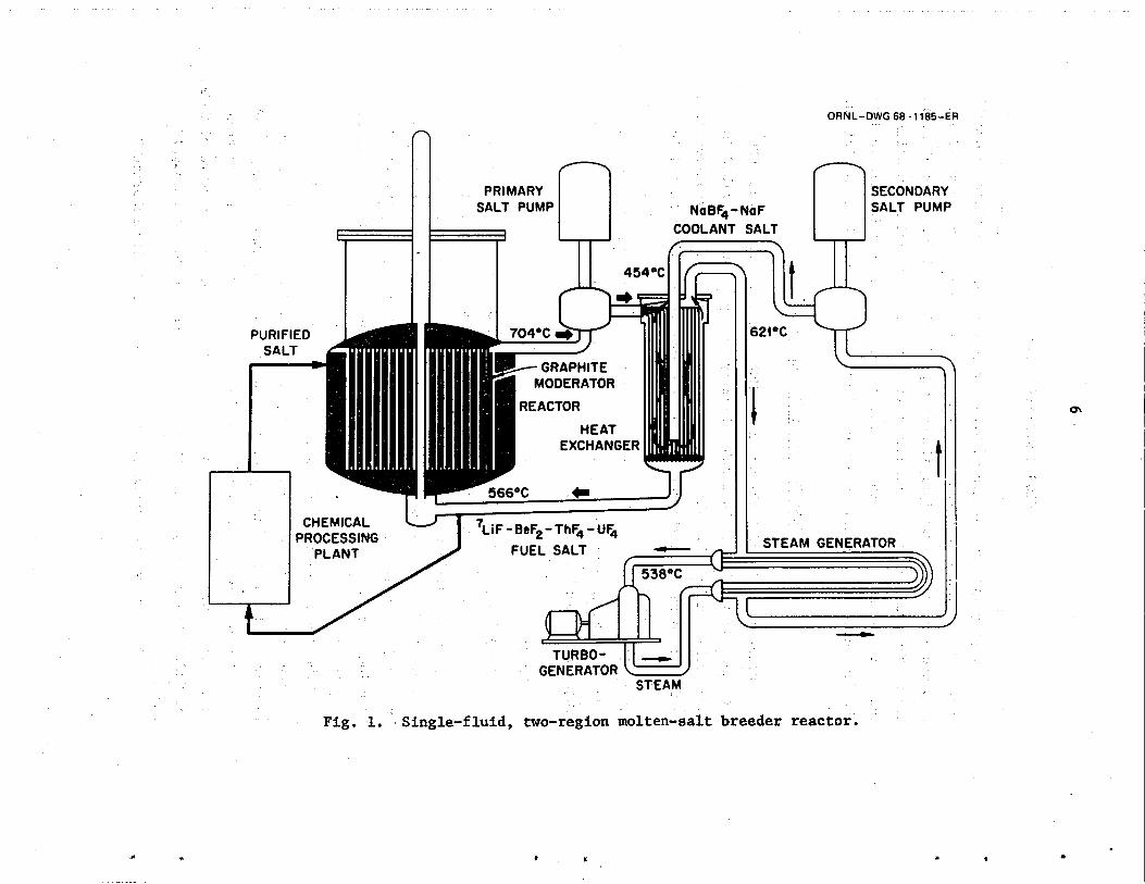
reference design MSBR, -shown schematically in Fig. l'and described in .some detail in'Ref. 1. This design (breeding ratfo * 1.07) resulted from
. _, an effort to restrict the.reactdr fissile inventory [1.5 kg/MW(e)l in order to maximizeythe conservation~of"uran&n~in. an expanding, but ulti-
_; .' . . mately limited,.nuclear economy. j Somewhat higher breeding ratios could
i have been obtained at the expense of higher inventories and correspondingly longer fuel doubling times'. : .:
/ i Reactor system _
, - The primary feature;in the MSBR design is a high-p&&density, well- thermalized, graphite-moderated 'reactor in which a single,molten salt con- taining both fissile and fertile.material'serves as both the fuel and '.- --:. .blanket fluid. The two major nkutronic:functions .(energy.production and . _~.. breeding) are achieved with a low fuel,inventory by varying the fluid &action fromi7about 13. vol % in the core region to about.37 vol % in the t .
The fluid fuel'consists essentially of a.molten mixture of 'LiF and BeF2 conta;ning.appropriite?luantities 0f;ThF.b and UFI, in a homogeneous solution. iThe molten fuel is'p~?ped.=from:the..core to heat exchangers where : heat'generated by fission (and other related nuclear processes) is trans- ferred to a molten,secondary' (or coolant) salt, a eutectic mixture of NaBF4 and NaF.* The secondary salt transports the heat to the steam supply
. *This mixture has frequently been called "sodium fluoroborate."
PRIMARY SALT PUMP NoBF~ - NoF
COOLANT SALT
ORNL-DWG 68-1185-ER
SECONDARY SALT PUMP
I t
GENERATOR STEAM
Fig. 1. Single-fluid, two-region molten-salt breeder reactor.
f L . (I .

i .
i 7
system and serves to isolate that system from the primary fluid, which
is thereby confined to the reactor primary containmentlsystem. The secondary salt also serves to intercept tritium migrating through the heat exchange system toward the steam circuit. '
The high degrees of radiological, chemical, and thermal stability
of the inorganic fluoride salts and. their low vapor pressures permit the operation of MSRs at relatively high temperatures (the nominal reactor outlet salt temperature is about 975 K) andfcorrespondingly high-tempera- ture, high-efficiency (nominally 44%), steam-electric power cycles. In
fact, the high melting temperatures of the salts (e.g., the liquidus temperature of‘the fuel salt is %775 K) require that these reactors be operated near the higher portion of the usual temperature range for fission
power systems. This high-temperature operation requires the use of high- temperature design and systems technologies and also allows the use of established high-temperature steam-power technology.
Fuel reprocessing
The fuel processing plant, or fission-product-cleanup system (Fig. 2), of the reference design MSBR'is conceived to operate continuously on a small side stream of molten fue1.5'6 This processing plant removes fission product'poisons for discard as waste. In addition, it removes 233Pa from the'fuel mixture and accumulates it within the processing plant where it can decay to high-purity 233U without, further exposure to neutrons. (Minimizing protactinium -losses through neutron- capture is particularly important at the high power density of the reference design MSBR and much less important-in designs that-operate at lower power densities.) ,_.
All the fis,sionproduct species do notgo to the,processing plant; :, krypton and xenon are removed by sparging with helium in the reactor. The seminoble and noble metals rapidly deposit on surfaces within the reactor
_ -.- _., .*-* ,__I . . _, - vessel and the primary heat exchanger; of these elements, only niobium ap- .< pears to plate preferentially on the surface:of the:,graphite moderator. Tritium diffuses through:the heat-ex&nger tube walls into the NaBFb-NaF
.- coolant, where most 'of it is retainedA -' '- .
Most of the separations are ac&mplished by selective extractions of cationic species from the molten fluoride fuel into bismuth containing

ORNL-DWG 78-572
Fig. 2. Flowsheet for fuel processing plant in reference design MSBR.
+ .

~
3
c
9
properly adjusted concentrations of lithium. Zr, U, Pu, Pa, the rare earths, and Th are extractable in that Such reductive extraction processes from fluoride fuel can effectively separate uranium from protactinium (but not from zirconium) and protactin-
ium from the rare earths and thorium. tially extracted from molten fluoride mixtures by bismuth containing moderate concentrations of lithium, but they are accompanied by an appre-
Beryllium is not extracted;
Rare-earth fission products are par-
ciable quantity of thorium. Separation of thorium from rare earths (and
from Y, Ba, Sr, Cs, and Rb, which behave similarly) must be accomplished by transferring all these elements (except thorium) to molten LiCl from
the bismuth-lithium alloy. 3 9 l 1
Uranium can be separated and recovered by reductive extraction, but
fluorination to UF6 is more effective and convenient. The UF6 and F2 are absorbed in a sufficient quantity of purified fuel solvent containing UFL,.~,~ Uranium in this solution is reduced to UF4 with Ha, and the re- constituted fuel salt is returned to the reactor after final cleanup and adjustment of the average uranium valence to about 3.99; Brp, I2 (and probably SeF6 and TeF6), which are volatilized with the UF6, pass through the sorber and must be removed from the off-gas stream.
A small processing plant is sufficient. The reactor fuel passes through the plant every ten days with a processing rate of 55 cm3/s (0.87
gpm). Table 1 summarizes the removal methods and cycle times anticipated for such a plant. The several separations required are well demonstrated in small-scale experiments, but engineering-scale demonstrations are still
largely lacking, and materials to contain both molten fluorides and bismuth +alloys seem certain to pose some problems.
Once placed in operation the reference design MSBR would.require no shipments of fissile material to reactor and only occasional shipments of bred excess 233U to actors. Accordingly, it would present a very low, and perhaps profile toward diversion by subnational or terrorist groups. However, as far as weapons proliferation - a national decision to exploit the machine to produce nuclear weapons - such a reactor has pronounced and obvious weaknesses. The uranium within the fuel is

Table 1. Methods and cycle times for removal of fission products and salt constituents in an MSBR processing planta
Removal Group Component time Primary removal operation
Noble gases
Seminoble and noble metals
Uranium
Halogens
Zirconium and protactinium
Corrosion products
b Trivalent rare earths
Divalent rare earths and alkaline earths
Alkali metals
Carrier salt
Kr, Xe
Zn, Ga, Ge, As, Se, Nb, Mo, Tc, Ru, Rh, Pd, Ag, Cd, In, Sn, Sb, Te
233u 23511 235 236 9 9 u, u,
237,,
Br, I
Zr, 2 3 3 ~ a
Ni, Fe, Cr
Y, La, Ce, Pr, Nd, Pm, Gd, Tb, Dy, Ho, Er
Sm, Eu, Sr, Ba
Rb, Cs
Li, Be, Th
50 sec
2.4 hr
Sparging with inert gas in reactor fuel
Plating out on surfaces in reactor vessel circuit
and heat exchangers
Volatilization in primary fluorinator; returned to carrier salt and recycled to reactor
10 days Volatilization in primary fluorinator followed by accumulation in KOH solution in gas recycle system
Reductive extraction into Bi-Li alloy followed by hydrofluorination into Pa decay salt
Reductive extraction into Bi-Li alloy followed by hydrofluorinat
10 days
10 days
decay salt V I
25 days' Reductive extraction into Bi-Li alloy followed by metal transfer-via LiCl into Si-5 at. % Li solution
Reductive extraction into Bi-Li alloy followed by metal transfer via LiCl into Si-5 at. 4, Li solution
25 daysC
10 days
*15 years Salt discard
Reductive extraction into Bi-Li alloy followed by accumulation in LiCl
a Adapted from Ref. 5. is not a rare earth but behaves as the trivalent rare earths. .
C Effective removal time -varies for the different elements.
P 0
. 1 u . .

11
clearly usable material for weapons, and its removal in relatively pure form by fluorination could be accomplished with little difficulty by use of the available processing system. Of course, such an action would be an overt and obvious treaty violation (the reactor could no longer furnish power), but given suitable other preparations the "warning time" could be quite short. Less obvious (and probably more insidious) routes for proliferation are, in principle, available. The reference MSBR produces more 233U than it requires; this 233U is generated in quite pure form in the protactinium accumulation system and is available via fluorination with the installed processing gear. obvious to an inspector, but successful removal would be undetectable for a moderately long perio It is probably easy to underestimate the dif- ficulties in such scenarios, The presence appreciable quanitities of
Attempts to remove it secretly should be
32U and of more than traces of fission products will add to the difficul- ties, but a well-planned and determined effort could obviously surmount them. than most reactor types to ,rapid results from an overt proliferation action and would offer significant opportunities for covert action.
As a consequence, the reference MSBR would seem more vulnerable
Reference Design Variations
Because of the perceived proliferation sensitivity of the reference design.MSBR, a brief study12 was undertaken in the fall of 1976 to deter- mine whether the basic concept could be modified to make it sufficiently proliferation resistant for wide deployment as a power producer. quirement for a positiverbreeding gain was eliminated, but the high- enrichment fuel composition was retained to completely avoid the need to deal with plutonium. a ,lower power density (higher fissile specific inventory) to reduce the significance of neutron absorptions in
The re-
The only other change considered in the reactor was
3Pa (if Pa isolation were aban- -.doned) and,to eliminate the need -for periodic replacement of moderator graphite in the reactor Five variants of the basic system, including
ssion-product-cle up concept, were considered. The first variation modified the 'reactor performance capability and
Such a system would eliminated the breeding of excess fissile material. have all the proliferation resistance (or sensitivity) of the reference

12
concept but would lack the potential for conthuous removal of fissile fuel while maintaining reactor operation.
The second variation eliminated all fluorination steps -the most
proliferation-sensitive procedure in the entire fuel-cleanup process. This would prevent the isolafion of 233Pa and would require more isotopi- cally separated 7Li, since uranium removal prior to f ission-product clean- up would be accomplished by reduction with lithium. It appeared that fuel self-sufficiency could be maintained in such a system with a reduced reactor power density (to limit Pa losses and reduce the relative poison-
f fect of other fission products) and significantly longer fuel processing cycle. quirement for 'Li. represent a significant increase in proliferation resistance..
The third variation involved a major change from the nominal fission- product-cleanup concept; it was proposed to substitute a CeF3 ion exchange system for all the chemical fission-product-cleanup operations. (Gas '
stripping to remove xenon and other volatlle fission products wouldr be retained.) tuting Ce, which has a lower neut of other fission products in the salt. formance would be experienced, but it appeared that self-.sustaining opera- tion could be achieved at the lower core power density. process completely avoided separation of the fissile material, it appeared to be significantly more proliferation resistant than the reference concept. However, the technical feasibility of this approach has not been demon- strated, and substantial research, development, and demonstration (RD&D)
would.be required to reduce it to practice if it is feasible.* I
The longer processing cycle would also reduce the re- The elimination of the fluorination steps was felt to
I ~
Such a system would remove only the rare earths (by substi- cross section) and leave a variety
Some degradation in breeding per-
Since this
The use of some form of vacuum distillation for fuel cleanup was proposed as a possible fourth approach to enhance the proliferation resis- tance of the reference reactor concept. eliminate many of the proliferation-sensitive steps, it was not clear that it would be workable with a salt containing'thorium. The technological uncertainty of this approach tended to rate it relatively low among the possgble alternatives.
Although such an approach would

13
The final alternative considered was the elimination of all on-site cleanup processes other than physical removal of noble gases. The poten-
tial,:feasibility of this approach was,based on some earlier studies of high-performance converter- MSRs in which the unprocessed fuel charge was
simply,replaced every few years. It appeared that, if reactivity varia-
.tions,could be managed, such a system might require replacement of-the
fuel charge only two (or,possibly three) times during the life of a reactor plant.' Although such changes would require the application of
additional safeguard measures, the infrequency of the changes was judged
to make this approach reasonably acceptable. Although some of the processing modifications to the high-enrichment
concept appeared to be clearly technically feasible and all provided some enhancement of,the proliferation resistance of the reactor, it did not appear that the antiproliferation gains were of,sufficient magnitude to justify an extensive effort to develop the reactor and the associated fuel-cleanup system: Consequently,~ nondenatured MSRs for power generation
at dispersed sites were not considered further. *
Plutonium Transmuter for 233U Production
.-It may be that any high-enrichment MSR would have to be located at
a site where special safeguards would be in effect and thus special-purpose
MSRs might also be acceptable. Of particular interest in this regard would be MSR systems that consume plutonium and higher actinides (produced by other reactors) and produce.!!3U.;forLdenaturing and subsequent utilization at dispersed sites.
Thermal or nea&he'rmal reactors' (which-include MS&) are inherently less'efficient~burners~of pluto&mi than are' fast ieactbrs~ and are at some ._ - , disadvantage in "fuel-factory" applications. However; MSRs have m&ma1
. parasitic absorbers in thei; cores, " "
I : need neitherhead~end reprocessing~
./ r steps‘ndr-"fuel element refab&Gtion;~"'
,. .I =l and‘have'a much smaller'in-process i
'inventory of product. !.
-Moreover,'~ the'MSR'-permits recovery of:'& '233U'--- product as'soon as it.is produced; hence, very.little of-the product - whose greatest value is ds'an export‘do&&lity~'- is consumed by'-f&ion
between replacements of solid fuel elements-as in the fast reactor system.

14
Thus, any advantages'MSRs might have as "fugl factories" would be related to thePr fluid fuel.*
The net production capability would be a major, but not the only, criterion for evaluatin,g "fuel factory" options. 0ther.significant cri- teria kould include the technological feasibility of the concept, indus- trial'acceptability, commercialization potential, safety and reliability, licensability, time to commercialization, and the probable net cost of the product. heretofore as safeguarded producers' of
*
Molten-salt reactor@ have pot been seriously considered 3U; perhaps they should be.
DENATURED MSR
MSR systems containing substantial .amounts of 238U have not been considered in most prior studies because of the perceived difficulties in,dealing with the plutonium that would be produced. systems would not be compatible with the high breeding performance and low inventories that have been among the traditional system goals. How-
ever, with the current emphasis on proliferation resistance and ultimate resource utilization in fission energy systems, MSRs fueled with denatured uranium may have significant overall technical advantages. MSR (DMSR) described in the following subsections is based on a preliminary
conceptual study of this system.
In addition, such
P
The denatured
c
It is anticipated that a more precise and detailed description will be evolved as the study is continued..
General Characteristics
The principal characteristics desired in a DMSR are (1) that it meet to the maximum extent practicable the c ntly perceived requireme
to proliferation of nuclear explosives and (2) that it provide ery high level of resource utilization.
At equilibrium,' the principal fissile material in the denatured tem is uranium with 233U and 235U in a ratio of about 1O:l. Sufficient
* Their,efficiency as net energy producers would be an advantage in
'Isotopic equilibrium for fissile uranium is effectively reached in comparison to accelerator-driven fuel
-'a few years and is' independent of whether startup was on 23sU or 233U.

15
238U is present in the mixture to dilute the 233U by 6:l and the 235U by
4:l. Additional denaturing is provided by the 234U and 236U in the steady- state mixture to achieve the preferred dilutions for nonproliferation.
Although.substantial plutonium is produced from the 23BU, the high neutron cross sections of the plutonium isotopes and the fact that all plutonium is retained in the fuel salt keep the total plutonium inventory relatively low; about-lo% of the fissile material is plutonium (239 and 241 isotopes). The long.effective,exposure time of the plutonium results in the buildup of substantial amounts of 240Pu and 242Pu. Although these isotopes have significant fission cross .sections (particularly at high neutron energies), they also undergo spontaneous fission (i.e., produce neutrons), which tends to detract from their value as explosives materials. In addition, there
is no provision for the isolation of plutonium from a number of other radioactive and otherwise undesirable nuclides. One other potentially attractive material is 233Pa, which is present to about 84 kg in the fuel salt at steady state. If this material could be isolated from the rest of the fuel,.it would eventually produce high-purity.233U, which would be proliferation sensitive. However, protactinium'isolation is not part of the conceptual system, and modification of the system to provide for such
'-isolation would be difficult, time consuming, expensive, and readily de- tectable. '
Utilization of all natural resources in the denatured'system appears
to be quite favorable. Significant amounts of 'LiF (and hence beryllium and thorium'.flu&fdes)* must be continuously removed from the fuel salt as"Li is added in the fissionLprodu&cleanup system; however, these materials could be-recovered .by'a 'variety of aqueous processes if it were economically attractive to dOCsol'". The effective breeding ratio can be maintained at 1.0, so that;aftertheinitial fissile loading; no fissile
~-~material need be'added 'or removed for 'the life of the plant; however, thor- '., '- -~ '- ium z&d 238U'must be added-continuously to'maintain the concentrations of
these nuclidesI" At &e&of-plant -life; only a small amount of addi- is
.Y'- tional'uranium would have--to be added 'to that'recoverable from the old
* These materials must.all'.be'included as potentially limited natural
resources.

plant (to sub
16
titute for plutonium th t is not recovered) to start up
a new plant. (including in-salt fission products, plutonium, and higher actinides) could be transferred to a new plant with no new fissile addition and no plutonium left over for storage or disposal.
Alternatively, the entire salt charge from a retired plant
The basic reactor flowsheet for the DMSR is essentially the same as . that for the reference design MSBR.
configuration, details of the fuel-salt composition, and the fission- product-cleanup (chemical processing) system. temperatures, pressures, and major flow rates, as well as the entire secondary system and balance of plant, would be the same as for the refer-
ence plant. The remainder of this section is devoted to those portions of the denatured concept that have not been described previously.
The only differences are in the core
Thus the primary-system
Reactor Characteristics
The principal criterion for an attractive DMSR is survival in a neutronic sense. It is axiomatic that adding 238U to a thermal spectrum MSR degrades its overall breeding performance because the plutonium that is produced has a lower effective fission neutron yield than 233U in such a system. In addition, it was recognized that protactinium isolation would not be acceptable and that neutron and bred 233U losses due to neutron captures in 233Pa would have to be accommodated. design problem became one of balancing a low core power density (to limit protactinium losses and graphite heating) against a higher fissile inven- tory in a core of reasonable size and balancing a more heterogeneous (lumped) core (to limit neutron absorptions in cooling problems in large moderator elements.
Thus, the nuclear
38U) against potential
One of the first requirements established for the DMSR was the need for break-even breeding. fluid-fuel reactors and to any other systems in which the entire fuel charge has one homogeneous composition.*
This requirement probably applies to all denatured
The actual "critical point" for ~- *
In such systems it is not possible to upgrade the average core en- richment by removing below-average (depleted) fuel and adding near-average (but still denatured) material.
.
17 3
operating feasibility occurs when the fractional rate of production of
.
fissile isotopes equals that of consumption of fissile isotopes with ap- propriate consideration of the rate of burnup of fertile material. At this point it becomes possible to sustain reactor operation indefinitely by additions 'of denatured fuel. For denatured feeds containing 13% 233U in-238U and 20% 235U in 23* U, the minimum acceptable MSR conversion ratios
are 0.98 and 0.97, respectively. However, such systems would be signifi- I cantly less attractive than a true'break-even reactor in that they would, require transport of substantial denatured fissile material to the site.
A DMSR must have an effective fission-product-removal system and must use the plutonium produced from 23*U efficiently to achieve break-even breeding over its lifetime. The plutonium and protactinium, as well as uranium, must be removed from the fuel before rare-earth and other fission
1 i products can be removed. 'Accumulation of 233Pa for decay outside the reactor- (as was planned for the reference MSBR) could not be permitted for the DMSRsince it would make high-quality 233U available with moderate ease. It is convenient to remove plutonium and protactinium together from the fuel and to reintroduce‘them immediately to purified fuel solvent for return to the reactor. Such retention of 23.3Pa in the reactor tends to lower the tolerable neutron flux (and the'power density) to limit losses of 233Paby neutron capture. This decreased power'density increases the fissile specific inventory for the system but also has some favorable effects.
1. If' the neutron flux x&t be reduced, it is reasonable to reduce . . -. it' to values that limit irradiation damage.in the'core graphite such that the graphite lifetime is equal to that of the reactor, thus eliminating - !,i -. .~ .the'need for scheduled moderator replacement.
,, _, I , ,,
i:;; : _ ~__
_ .* ; . ‘2;' 'At the lower neutron flu$the xenon poison fraction for a given . . - /. ,.I- _"
xenon concentration is reduced,'thereby possibly eliminating the need to ~.L',.. ., -'
impregnate"the graphite.~'surfaces to reducetheir permeability to gases. 'i p -- .,* I)
3. The'attendant~lower graphite power densities lead to lower tem- . perature rises~in'the graphite,'
'. ,\. .- j :, thereby substantially easing-the design ;‘-' " . .
constraints on moderator elements.
.
4. The poison fraction associated with the shorter-lived fission products is somewhat reduced, providing slightly more margin for operation.

18
Core configuration
Consideration of the above factors led to the selection of a nominal
reference reactor concept with the characteristics described below. cal reactor about 10 m in diameter by 10 m high, in-
cluding the ref neutron damage flux to the graphite with little influence (at these large
sizes) from criticality or conversion ratio. Hence, effective flux flat- tening in the core might allow selection of a spaller reactor size or a longer graphite life with minimal reactivity penalty.
tor. The core size is determined primarily by the
,
2. A nominal fuel fraction in the core zone of about 13%, subject to optimization and minor spatial variations (axial and radial) for flux flattening.
3. Absence of a high-fuel-fraction "blanket" zone, comparable to *the 37%-salt zone surrounding the core in the reference design MSBR.
zone was used to help limit neutron leakage in the original breeder con- cept.
This
4. Simple cylindrical design (25 cm OD) for the graphite moderator elements with relatively large-diameter (QS-cm) central fuel passages. Refinement of the design might lead to modification of these properties.
This basic reactor design appears to meet the neutronic and thermal- hydraulic requirements of the system while providing latitude in several areas (core size, fuel fraction, and moderator-element size and shape) for adjustment of the system performance to cover uncertainties.
In addition to- the above features, the reactor would include salt inlet and outlet plenums (between the core and reflector) at the bottom and top of the core that would be characterized by high fuel-salt volume fractions. A similar, though smaller, salt zone would be present between the core and reflector in the radial direction to accommodate the differ- ential thermal expansion between the metal reactor vessel and the graphite moderator. outward as the vessel expands on heatup.) included in the conceptual design.
(The reflector is attached to the vessel so that it moves The effects of these zones are

19
Neutronic properties
Nuclear composition and the basic fuel cycle. The reference graphite and fuel characteristics and compositions are shown in Tables 2 and 3. The isotopic composition of the actinide component of the fuel at equilib- rium depends on the refueling policy, the removal process, and the flux- averaged cross sections. The fuel circulation is rapid, so that fuel everywhere in the core can be assumed to have one composition.
After startup, the basic refueling'policy is to add thorium con- tinually in the amount required t o hold the concentration constant and to add 23eU as required to satisfy the "denaturing inequality," N23eU 2 6N233U + 4N23sU , where N refers to nuclear number density. The actual amounts fed at equilibrium, assuming a 0.75 capacity factor for a 1000- MW(e) plant, are 601 kg of thorium and 116 kg of uranium per year. Thorium
Table 2. Reference characteristics of fuel salt and moderator for a denatured MSR
Cliaracteris tic Yalue
Graphite moderator density, Mg/m3 1.84 Fuel-salt density, Mg/m3 3.33 Salt volume in reactor vessel, m3 Salt volume outside reactor vessel, m3 Core salt-volume fraction 0.129
80 '23
Table 3.. Nomi composition of~fuel salt
Molar percentage
'LiF 71.7 BeF2 16.0 XFba 12.3 Fission products Trace
a X refers to all actinides.

20
represents 84% of the total feed on either a molar or a weight basis, and either depleted or natural uranium could be used with only insignificant differences. (Pure 23eU was assumed in these studies.)
-
. A fission-product-cleanup process much like that described for the reference design MSBR (see also Table 1) ie presumed to operate contin- uously to remove materials from the fuel salt. -day processing cycle was assumed for the denatured system (vs 10 days for the reference MSBR) , so that effective removal times from Table 1 are approximately doubled for those elements* whose removal is a function of the processing cycle differences from the refe reprocessing concept are:
A
cle that. arise from anges in the nominal t
1. The 233Pa remains with'the fuel, salt indefinitely rather than being isolated on the nominal 20-day processing cycle.
2.
3. The transplutonium actinides are recycled into the fuel salt. Selenium and tellurium are removed with the halogens on the
nominal 20-day processing cycle rather than?plating out on metal surfaces on a very short cycle.
4. Fission-product zirconium, because it requires a special separa- tion operation, is removed on a rather long (Q300-day) time cycle.
5.
The breeding and burning of fissile fuel proceed aPProfiatelY as
The fuel carrier-salt replacement cycle is about 7.5 years.
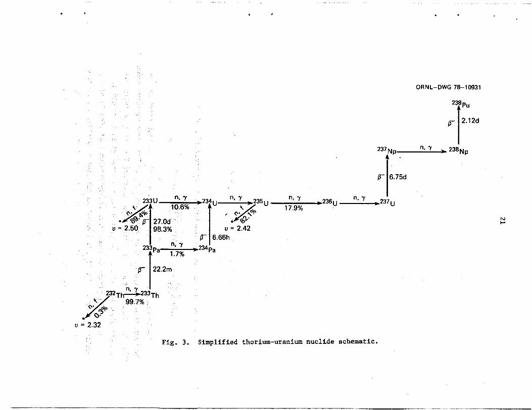
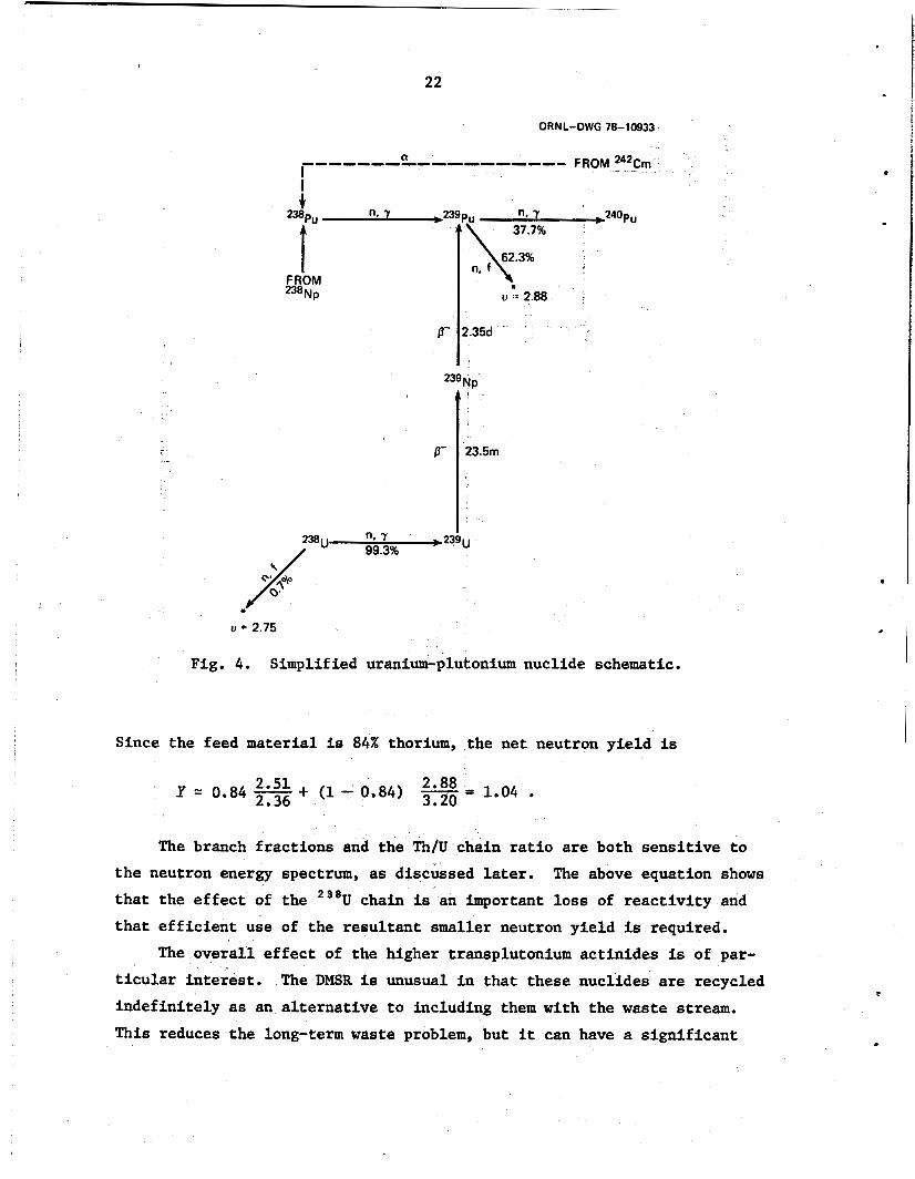
shown in the nuclide charts (Figs. 3 to 51, which illustrate the Th-U UJPu, and transplntonium chains in the DMSR,-respeetively. actual Granch fractions depend on tfie flnx level as well as the energy
Although the
distribution of flux, these simplified chains indicate the potential for a mixed-fuel breeder. 2.36 neutrons absorbed and 2.51 neutrons produced for each thorium atom consumed in the 232Th chain, while the 23eU chain has a "cost" of 3.20 neutrons and a yield of 2.88. neutron yield gives a small surplus to account for nonactinide losses.
The data shown on the figures indicate a total of
From this, we can see that a combined
* Halogens, corrosion products, trivalent and divalent rare earths,
'The modified reprocessing concept is described in more detail in a alkaline earths, and alkali metals.
later section.
' !
. .
I
U
6- I 6.66h
234 pa
,236 u n, Y 1 7.9%
"
OR N L-DWG 78-1 093 1
ne , , 2 3 8 ~ ~ 237 N p
0- 6.754
n, Y I - -237 u
N r
u = 2.32
Fig. 3. Simplified thorium-uranium nuclide schematic.
22
n. Y d 3 9 P u ,240PU i
37.7% 238P"
62.3%
ti -= 2.88 FROM 238Np
u = 2.75
Fig. 4. Simplified uranium-plutonium nuclide schematic.
Since the feed material is 84% thorium, the net neutron yield is
2.88 Y = 0.84 2.51 + (1 - 0.84) 3.20 = 1.04 . 2.36
The branch fractions and the Th/U chain ratio are both sensitive to the neutron energy spectrum, as discussed later. that the effect of the 238U chain is an important loss of reactivity and that efficient use of the resultant smaller neutron yield is required.
The above equation shows
The overall effect of the higher transplutonium actinides is of par- ticular interest. The DMSR is unusual in that these nuclides are recycled indefinitely as an alternative to including them with the waste stream. This reduces the long-term waste problem, but it can have a significant
. .
TO
16.0h 82%
u = 2.94
ORNL-DWG 78-10934
IO.lh
\rn
u = 3.7 u = 4.5
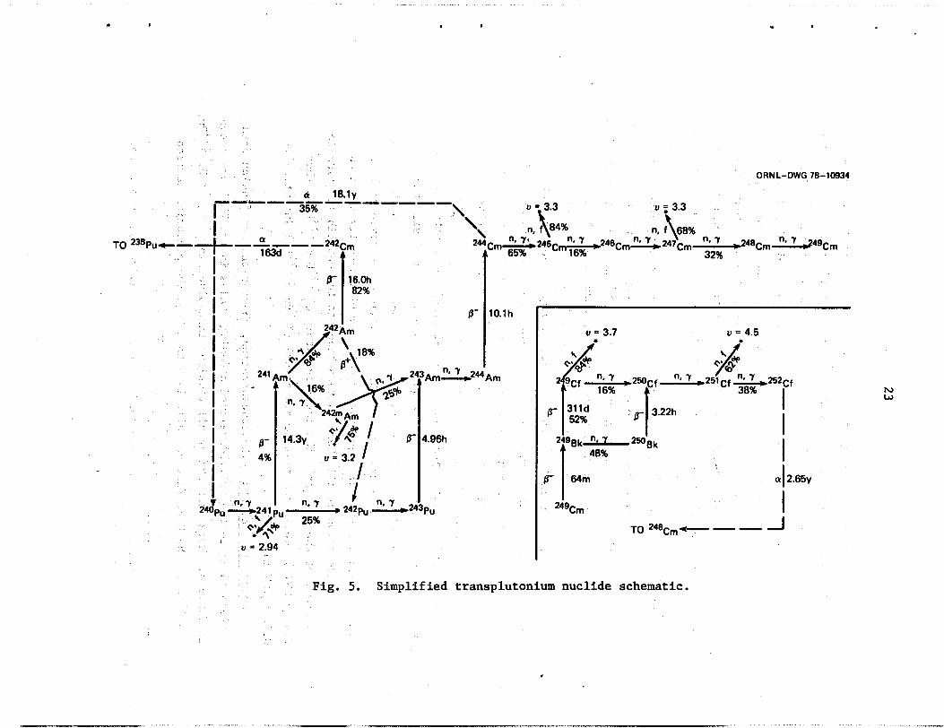
. Fig, 5. Simplified transplutonium nuclide schematic.
h, w
24
effect on the neutron yield of the system. operation study show that each atom of 240Pu produced from 239Pu is joined
and 242Pu reactions are taken as-a part of the transplutonium effect, we can characterize the total ef fect as llows: 242Pu calculated without the transpl tions, 1.0 additional fissions, and 3.2 ’additional f iss born. The net result is a loss of 0.8 neutron per )*nor
Data taken from a 200-year
by 0.11 atom produced by 01 decay of 244Cm. If the additional 240Pu, 241Pu, 8
For each absorption in nium’ chain, 4.0 additional absorp-
eutrons are orption in
and 24’Cm, in descending order, are the largest neutron contributors iated with the higher actinides. At the low power density of this system, the (r decay of 244Cm leads to an impaired neutron yield compared to that at higher power densities. Also, the
of 241Pu becomes-a nontrivial loss of fissile material. Neutron absorption in 233Pa represents _ . _ - . - a significant c loss of reac-
tivity in this concept, since each atom would otherwise decay to a fissile 233U atom yielding 2.2 neutrons directly for each absor tion. sorption in protactinium leads to another in 234U-before a fissile material is finally produced. Higher power density would make this situation worse.
Each ab-
The nonfissioning capture in 235U is similarly unprofitable. of three additional captures areTequired to produce a fissile nuclide, 239Pu. example, 236U would saturate with a time constant of approximately 30 years.
A total 1
Some of these chains would take many years to develop fully; for
Even so, the full equilibrium value would eventually be reached. Consideration of all these factors leads to the equilibrium fissile
-
inventory of the reactor. 2.4 kg/MW(e), while the fissile plutonium* (239Pu + 241Pu) 0.16 kg/MW(e),
The tota inventory of 2 3 3 ~ + 2 3 5 ~
Neutronics results. The concentration, absorption, and fission data corresponding to the fully developed breeding chains in the DMSR are shown in Table 4. and 241Pu.
. I F
More than 98% of a11 fissions take place in 233U, 235U, 239Pu, The U/Pu fission split is 5 to 1, but the plutonium neutron
* The total plutonium inventory is about 0.37 kg/MW(e), so only about
43% is highly fissile.

-
25
=
i
Table 4. ,Nuclide concentrations and reaction rates in the DMSR after long full-pokier operation
Nuclide Concentrationa Fission (x1o24)
Neutron b absorption fraction
232Th 233Pa 233u
23’~
23Su
236”
:::"P U 239Pu 240Pu 241Pu 242p;
TransplutoniumC
Total actinides
Fluorine Lithium Beryllium
Total fuel salt
Graphite
Fission products
Total
3,211.0 2.12
54.7 24.0 6.07
10.0 2.01
348.0 2.69 1.63 1.26 3.43
47,800 22,400 '5,010
92,270
0.32775 0.00248 0.00396 0.00001 0.32284 0.75133 0.03420 0.00043 0.03403 0.07272 0.00610 0.00008
‘ 0.00607 0.00005 0.06769 0.00119 0.06723 0.10896 0.02538 0.00006 0.02435 0.04687 0.00635 0.00006 0.02605 0.01577
0.9520 0.008 0.007 0.001
1.00000
0.968 0.020 0.004
0.992
aNuclei per cubic meter of salt or moderator. b Absorption per neutron born; leakage is 0.008.
CIncludes.some 2toPu, 241Pu, and 242Pu produced from a decay of 244Cm. i ,, i _ ,,.
J : _. _I
- ~C
-..yield per fission is significantly higher. --Neutron leakage is only a ._ . : _- small loss in this system, and captures in nonactinide nuclides are also
ly. The neutron utili&tion can be summarized as follows: 1 ,~ _' .: .: -- 'Absorber-type, Absorption (Z)
i : Actinides 'I-. Q. ,.- 95.2. Nonactinide salt nuclides 1.6 Fission products 0.4 Graphite 2.0 Leakage 0.8

26
The depression of thermal flux in the fuel is of some interest because it governs the allowable size of the moderator logs from a neutronics standpoint. If the flux depression is large, graphite and resonance cap- ture will be enhanced. Table 5 shows’that flux depression would not be excessive in the reference core design.
Table 5 . Fuel disadvantage factors
Neutron energy Inner fuel Moderator Outer fuel group zone zone -- ~ ~~
1 (fast) 1.18 , 0.98 1.11 ’
2 (resonance) 1.00 > 1.00 1.00 3 (thermal) 0.92 1.01 0.95
The spatial peaking factors for both power density and fast-neutron flux (E > 50 keV) have significant effects on moderator graphite lifetime in MSRs, particularly in the low-power-density concepts where a moderator lifetime equal to that of the reactor system is desirable. density distribution primarily affects the graphite temperature, which in turn affects the amount of graphite damage for a given neutron fluence; the neutron flux directly affects tpe carbon-atom displacement rate as well as the temperature. and neutron flux are the same in the nominal core design, both in the radial and axial directions; the values are 1.69 and 1.35 for radial and axial directions, respectively. The core average neutron damage flux is 3.1 X 10l3 neutrons/cm2-sec (E > 50 keV). neutrons/cm2 is assumed as the limit of useful would be reached in the highest-flux region in 13 equivalent full-pow years (17.3 years at 75% capacity factor). the upper limit for damage fluence and flux flattening may allow an exten- sion of the useful graphite life to the desired 30 years at 75% capacity factor.
The’power-
The peak-to-average values for both power density
If a fast fluence of 3 X
Less conserv
Startup and control. The startup of the denatured system can be accomplished with either 233U or 235U at the appropriate denaturing level.
= I
P

27
The e f f e c t of t he denaturing is such t h a t e i t h e r f u e l w i l l give approxi-
mately t h e same performance.
t h e i n i t i a l f i s s i l e loading, as shown by Fig. 6. The ca lcu la ted f i s s i l e
loading required t o achieve i n i t i a l c r i t i c a l i t y and overcome equilibrium
f i s s i o n product loading is 2371 and 3115 kg f o r 233U and 235U, respectively.
Figure 6 a l s o shows t h a t a 2% e r r o r i n the c r i t i c a l i t y ca lcu la t ions could
be compensated by .a 5% change i n f i s s i l e loading.
The i n i t i a l r e a c t i v i t y is very sensit ive t o
Af te r s t a r t u p , an increase i n r e a c t i v i t y on the order of 2.5% w i l l
occur due t o the g rea t e r e f f e c t of buildup of new f i s s i l e material over
t h a t of f i s s i o n products.
accomplished by withholding uranium from the input stream. A short-term
increase could be accomplished by reducing the thorium content, although
t h e long-term e f f e c t of t h i s ac t ion might be less f i s s i l e production.
Thus, r e a c t i v i t y increases would more l i k e l y be provided by small f i s s i l e
additions.
Short-term reduction of r e a c t i v i t y could be
ORNL- DWG 78-10932
FRACTIONAL CHANGE IN'LOADING OR MENT (%I
E f fec t of i n i t i a l loading and enriched makeup on equilibrium Fig. 6. r eac t iv i ty .

28
'I Long-term breeding and nuclear .design flexibility.- ‘The-neutronic
-'calculations indicate that the%kR would'start *and- run' for the life of the moderator on fuel'which it manuf&tured internally. However, more is:ex-
$&ted' of it. In. this-scenario, it'is intended 'that the fuel be recycled "indefinitely in .a‘suc&sion of n& react&as the useful life of the" old
- ones ends;' 'This would'eventually 'lead to a buildup of the “tiash”, nuclides
(2361J, 237Np, 23*Pu, 242Pi, and the .various americium and 'Curium nuclides). . Of these, the data used -for 238Pu and the various'amerieium' and
curium n&ides 'must be described as estimates and are perhaps subject to . . errors'of 30% or more." If .these- chains develop as predicted; 'the ultimate effekt 'would be a slow approach-after n&y years to'an absorption fraction of-O;0633 {including Plutonium and'transplutonium.effe&) due to: absorp- tion $238 Pu, with a yield of 0.0377'for a net loss of 0.026.- present &lculations 'indicate"that a system using'~this .fuelWould'be no more than
. barely critical if the calculations were accurate.
What can be done if these predictions are true? What if reactivity is even lower than predicted? Potential alternatives for increasing the overall system reactivity include (1) altering the spectrum to improve neutron production, (2) enriching the 238U added, (3) altering the fuel salt processing concept, or (4) adjusting the denaturing limit to reduce the 238U additions somewhat. The potential for improvement by spectrum modification seems attractive. Certainly the fission neutron yield is sensitive to-the energy spectrum. To illustrate this point, Table 6 shows a three-energy-group structure used in some of the analyses. Absorptions in groups 1 and 2 show a net loss of neutrons,,while there is a gain in group 3. Thus the neutron yield is sensitive to ,the ratio of group 2 (resonance) absorption to group 3 (thermal) absorption and thus to the fuel/moderator ratio. The relative importance of group 1. (fast) absorp- tions is small because-both absorptions and productions are much smaller
than for the other two energy groups.. Some additional 'information on the spectrum effect may be.-obtained-.by.intercomparing.the group-average neutron absorption cross sections and the effective neutron yields for some of the heavy-metal nuclides in this threelgroup structure (Table 7). For example, it is clear from a komparison of the Th/ 238U cross-section ratios in the resonance and thermal groups that the ratio of Th/238U neutron.absorptions
.

-29
i
Table 6. Three-group-neutron structure and reaction rates for the postulated DMSR
Group Energy range
Flux Relative Fission Net volume neutron neutron fission
absorption production source
1 14.9-1.00 MeV 21 0.008 0.005 0.69 2 1.00-0.55 eV 223 0.378 0.197 0.31 3 0.55-0.005 eV 145 0.606 0.798 0.00 -- Total 389 0.992 1.000 '1.00
Table 7. Selected cross-section data for fissile/fertile nuclides
Group
1 (fastja oa 0.19 2.2 rib 1.2 2.6
2 (resonance) oa 1.6 51 17 0.00 2.1
3 (thermal) *a 3.0 250 rl 0.00 2.3
1.5 0.51 2.1 2.0 0.81 2.6 2.4 3.2 3.1 2.1
25 5.8 28 39 \ 53 1.6 0.00 1.7 2.4 0.00
274 1.2 1400 1000 16 2.0 0.00 1.8 2.2 0.00
aSee also Table 6. b Defined here as,va /a .fa*: j I
_ I
) . ’ I ,
:. would.be increased.by.reducing the resonance flux in relation-to the ther- . ma1 flux. The.same.would be true of the ratio of ?33U/Th absorptions. In .: _. this:system, almost every.neutron absorption in thorium also results in a , , _ neutron absorption in 233U; thusi an increase in the absorption effective- _~ nessof ?33U with.reduced reqonance,flux leads to a lower allowable in-
ventory*of 2?3U-relative.to-thorium.,,Since the required.-23eU inventory
is governed,principally by the amount of 233U present, this also leads to a lower . 23*U loading. Both of these effects work to increase the relative
30 '
importance of the more productive Th-233U chain (as kasured by the higher weighted-average value of n for 23 in this spectrum)
All these factors tend to make the neutron yield larger when resonance flux is reduced by increased moderation. the 'tendency of the resonances in "*U t
is reduced. results in more absorption in nonactinide salt nuclides and graphite. Also, it is necessary to increase the moderator volume fraction to make the resonance flux lower. tions, which tend to offset the beneficial effects of the more-thermal spectrum.
This effect does not dominate, however. A thermal spectrum
These effects result in more parasitic absorp-
In the reference MSBR, a "blanket" with a relatively high salt frac- tion and a harder spectrum was used around the optimum-spectrum inner core. This tended to increase reactivity,-with the fissile material being pro- duced in a hard spectrum with low-parasitic capture and consumed in a softer central spectrum. Although the resulting core would be more com- plicated (and difficult to 'Ihanuf acture) , the alternative might be accep- table if one were required to provide the added reactivit
of 238U added would remain as before, but some 233U would be added. Figure 6 shows the effect of enriching the 238U mak amount
If the material were enriched to the nominal denaturing limit, 'U% of reac- tivity could be gained. This would require special protection of the material added, but the amount would be only 155 kg of fissile material per year. could also be used with somewhat inferior results.
A 50% enrichment would yield 7% of reactivity.
Enriched 23sU
Since fission products constitute only a very small reactivity loss in this concept (cf. Table 4), the reactivity gain that could be realized by modifying the fission-product-cleanup process probably i However, in the equilibrium fuel mixture , there I s significant poisoning associated with neptunium, plutonium, and the transplutonium actinides. Thus, removal of some of these materials,'possibly between movements of the salt from one reactor plant to another, could effect a significant extension in the useful life of the fuel charge. entire fuel charge could be consigned to storage or'disposal at the end of life of a given reactor.)
'
(In the limit, the
It seems apparent, however, that this
*

31
approach would have an unfavorable effect on the antiproliferation at- tributes of the concept.
The final option - reducing the denaturing ratio -may be inferior to the other three from an antiproliferation viewpoint, although it would not add to the fuel cycle cost as would enriching the feed material. Allowing the 233U denaturing factor to drop to 4 as for 235U would produce a 0.7% increase in reactivity. improve the reactivity but would decrease the proliferation resistance of the system.
Further reductions in the 23eU loading would also
In summary, it appears that an attractive, proliferation-resistant DMSR with break-even breeding is neutronically feasible and that suffi- cient latitude and alternatives exist to ensure its technological success in this area.
Core Thermal Hydraulics
The reactor core t -hydraulic feat 6 , particularly with respect to graphite temperature considerations in the reference design MSBR.
straints are considerably relaxed in this area for the DMSR, they remain significant from the standpoint of overall technological feasibility of the concept.
enon transport to the graphite, were major Although the design con-
Because of the relatively low power density of this reactor concept, simple core configurations whi were not possible in the MSBR reference design' may be considered. Th simple designs were considered: (1) a
core made up of spaced graphite slabs, (2) a core made up of stacked hex- agonal graphite blocks with circular coqlant chann sisting of 8 hexagonal array of graphite cylinders with central coolant channels.
d (3) a core con-
Constraints which must in selecting a core design in- clude maximum graphite'element t ture, local salt volume fraction, and the 38U self-shieldin oses a minimum limitation on the coolant channel dimensions. ure rise between the coolant channel and the hot spot in the graphite moderator element is especially important because of the strong dependence of graphite dimensional change
.
32
ature. The salt volume fraction and the 238U self-shielding effect strongly couple the thermal-hydraulic and the neutronic core designs.
These combined constraints appear to rule out the possibility of a graphite slab core configuration. loss of coolant channel geometry due to shifting of the stacked hexagonal
Mechanical problems, especially the
ule out the second option. The third design seems t o fill all the
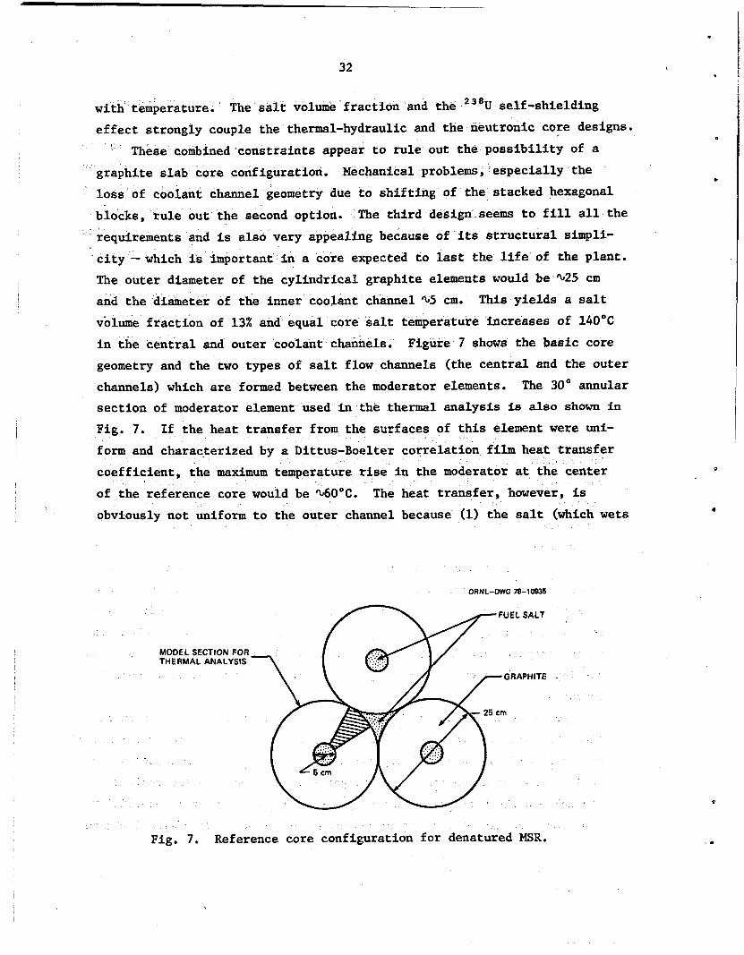
equirements and is also very appealing because of its structural simpli- city -which is important in a core expected to last the life of the plant. The outer diameter of the cylindrical graphite elements would be %25 cm and the diameter of the inner coolant channel %5 cm. volume fraction of 13% and equal core salt temperature increases of 14OOC in the central and outer coolant channels. Figure 7 shows the basic core geometry and the two types of salt flow channels (the central and the outer channels) which are formed between the moderator elements. The 30' annular section of moderator element used in the thermal analysis is also shown in Fig. 7. If the heat transfer from the surfaces of this element were uni-
form and characterized by a Dittus-Boelter correlation film heat transfer
This yields a salt
the maximum temperature rise in the moderator at the center of the reference core would be %60°C. The heat transfer, however, is obviously not uniform to the outer channel because (1) the salt (which wets
ORNL-DWG 78-10935
MODEL SECTION FOR THERMAL ANALYSIS
25 cm
Fig. 7. Reference core configuration for denatured MSR.
,
33
graphite poorly) will not penetrate all the way to the point of contact of the moderator elements, (2) the salt velocity near the point of contact will be greatly diminished, and (3) regions of, low salt velocity will have temperatures greater than the channel average because >90% of the power.is generated in the flowing salt. In addition, the Dittus-Boelter correlation may not apply, because a thin film of helium may exist on the graphite surfaces.
In the absence of information on salt heat transfer coefficients, penetration depths, and turbulent velocity profiles, an estimate (probably conservative) of the moderator temperature structure was obtained assuming ' a salt film heat transfer coefficient of 0 within 15' of the point of moderator contact and a salt film heat transfer coefficient equal to 80% of the value obtained using the Dittus-Boelter correlation elsewhere.
With these boundary conditions, the heat conduction equation in
cylindrical finite-difference form was solved in the 30" graphite section using the method of successive over-relaxation. Constant heat generation
and thermal conductivity within the graphite were assumed. This analysis yielded a maximum graphite temperature 80°C above the salt temperature at the core center and a maximum graphite temperature in the core of 74O'C at an axial location 2.1 m,downstream of the.core midplane.
The hydraulic diameters of the central and outer channels are 5 and 2.6 cm, respectively, which means the central channels will need to be orificed to more nearly equalize the salt velocities and hence the salt tempera,ture rises in two channels. ;Thjs.could possibly be achieved by . . machining small channels in.the graphite near the inlet and outlet ends. The possibility of spacing the moderator,.elements to eliminate the prob- lems caused by .low heat transfer and low salt velocity near.the contact points has been investigated, but at present it appears. this would entail _
.a salt volume fraction significantly greater than 13% to be effective.
..-. Chemical Processing
Unit processes and operations generally similar to those in.the flow- sheet for the reference MSBR can:be used to process fuel from the DMSR; Processing for the latter reactor has not yet been analyzed in detail,
34
but it is clear that the flowsheets must differ in some important aspects. The fuel volume in the DMSR must be considerably larger, and, although the cycle time can probably be appreciably greater than 10 days, the processing plant will be The DMSR will contain a considerable quantity of plutonium which must be retained within the reactor circuit. the reactor core and allowed to decay must obviously be abandoned since such a system would furnish weapons-usable 2 3 3 U upon treatment with FP. Since protactinium and plutonium, along with uranium, must be removed from the fuel solvent before yttrium and the rare-earth fission products can be removed, the DMSR must contain a system which provides for removal of plutonium and protactinium and minimizes proliferation opportunities by immediately reintroducing them to purified fuel solvent for return to the reactor.
mewhat larger than that of the MSBR.
The MSBR system in which 233Pa was accumulated outside
Such a protactinium-plutonium reintroduction circuit has the nsiderable disadvantage compared with the MSR plutonium accumulation
system that it also reintroduces fission product zirconium to the puri- fied fuel solvent. However, the protactiniunr-plutonium reintroduction cir- cuit has the advantage - insofar as waste management is concerned -that it also reintroduces americium, curium, californium, and plutonium to the reactor fuel and permits only very small losses of any transuranium elements to the waste streams.*
It seems apparent that the DMSR can manage the noble-gas and the semi- noble and noble-metal fission products in the manner and with the same removal times described earlier (see Table 1) for the MSBR.
the DMSR with 5 to 10% of the uranium present as UFi, as seems feasible, would apparently result in essentially immediate reduction of fission product selenium and tellurium to Se'2 and Te'2 and their complete reten- tion (with little or no interaction with the Hastelloy N) by the fuel. Any other seminoble and noble-metal fission products that appear appreci- ably in the fuel stream to the processing plant could be effectively re- moved by a simple wash with bismuth containing no reducing agent.
Operation of
* Of course, it is not known whether solid LiF-BeFz-ThFb containing
fission products can be considered a suitable form for disposable waste. It does seem certain that very low levels of transuranium nuclides will offer some advantages whatever the waste form.

i
35
.
The DMSR processing flowsheet, shown as a simplified block diagram in Fig. 8, would recover about 99% of the uranium by fluorination to lJF3
i
and would reintroduce it,to purified fuel solvent as proposed for the MSBR. The quantity of UF3 to be produced and absorbed per unit time would be several-fold larger than that for the'MSBR. Also, if the DMSR were operated with 10% of the uranium as UF3, the quantities of SeF6 and TeF6 to be recovered by the off-gas.treatment'system would be-markedly increased.
Fission product zirconium is produced in high yield, and its removal from the fuel is highly-desirable. Although the zirconium isotopes are
'not important neutron absorbers, any contained zirconium must be reduced with expensive 'Li and reoxidized each time the fuel is processed. It should be possible to remove zirconium-(on a cycle time of about 200
days) by partial extraction - along with a portion of the uranium, plu- . tonium, protactinium, and transuranium,elements - in bismuth containing a small concentration of lithium followed by selective and essentially complete reoxidation of plutonium, protactinium, and the transuranium
elements into purified fuel solvent in a multistage operation.* The pregnant solvent from this operation serves as the absorber solution for the lJF6. Since the zirconium-bearing bismuth solution cannot be completely freed from the 238U-233 U mixture by selective oxidation, the -, zirconium ‘and uranium must be transferred by hydrqfluorination to a waste fluoride salt and the uranium recovered as UF6' by fluorination before discard of-the waste salt at a rate corresponding to about 4 moles of zirconium per day. A.simple method-for zirconium removal on a much shorter
t. cycle time-'would be very -desirable~ and may-be-possible. - i .: . ; ._ ,: '. I '-. J . : :- y ;
* ". . ..' This reoxidation of plutonium and,protactinium-must be essentially
quantitative since,.:any of .thesey elements (and the other transuranium ele- ments) t$at remain with the zirconium arelconsigned-with the zirconium to waste. ;, :
t . :+ - _ _ I
.- + . Zirconium is-known.to:form a very stable intermetallic compound (Zr*
Pt3) with platinum.13 This-compound‘should" form whenzfuel containing 10% of the uranium asjUF3 isiexposed to platinum, and thelZ"rPt3 can be decom- posed to dissolved'ZrF7- and solid platinumupon,hydrofiuorination in the presence of molten fluorides. It appears that .neither‘uranium nor thorium would be removed with zirconium from the fuel mixture'& platinum,14 but there is no information about protactinium, plutonium, or other trans- uranium elements.

+ f
ORWL DWG TI-STS
Fig.'8. Preliminary flowsheet for fuel reprocessing plant in a denatured MSR,
b , .
8 1

c
37 I
If the partial reductive extractionof zirconium were used, the fuel salt would then pass to a multistage extractor.where .the balance of the
zirconium, uranium, plutonium, protactinium,,and transuranium elements
i would be recovered by extraction into a bismuth-lithium alloy at somewhat higher lithium concentration. By use of about six countercurrent stages with lithium in'bismuth maintained at about.2.15.x lo-3 atom fraction, the protactinium losses can be kept to completely negligible values and
the,plutonium losses can be made very satisfactorily low.* The pregnant
bismuth,(containing U;Zr, Pu, Pa, etc.) would be sent to the UFs re- duction and final valence adjustment stages, where the values would be recovered in the fuel-for return to the reactor. The fuel solvent (LIF-BeFz-ThFb containing a very large fraction of yttrium, the rare- earth, alkaline-earth,.and'alkali-metal. fission products) from this extractor passes to the rare-earth extraction column.
The process for removing yttrium and rare-earth, alkaline-earth, and alkali-metal fission products.from the fuel solvent is the same as that proposed and described above for the MSBR. The effective removal rates
of the several fission products depend upon the element removed and upon the size, flow rates, and number of effective-stages in the rare-earth extraction,-transfer, and,stripping systems. However, it appears that by processing 5% of reactor inventory per day (a number that may prove uneconomically;.large), the rare earths and barium could be removed on a cycle time well below 100 days. Such removal would require discarding about 100 moles of lithium per day through hydrofluorinatlon of the rare earths into waste salt. Cesium could be removed with a cycle time of 100 days by discarding about 100 moles of LiCl per day.
. . : '~ Since'the quantities::of uranium-.plutonium, ,zirconium, and.trans- -'uranium-elements -that'&& be"reduced and &oxidized are much larger than .=" -' ;
in the,MSBR,:the use ofVli&ium by the'DMSR will be relatively large. On '. a 20-day processing cycle;"about'2000. moles'bould‘be required as red&ant ~. ; . :
: : each day.(with most of.this-entering the fuel)..: .This corresponds to about -... t " I ._ ._
,,_ :: :'
.
.
i _ *It appears-that protactinium losses-could be kept'to less than 25 g/year and plutonium losses. to about 100 g/year in the combined zirconium- removal system and the main extractor.

38
0.05 m3 (1.8 ft3) of purified fuel salt that must be removed each day.* About 280 moles of ThF4, 7 moles of 23*UF4, and 430 moles of BeF2 must be added each day. These removals and additions constitute replacement of the fuel solvent (LIF-BeFz-ThFb) once per 7.5 full-power years of opera- t ion.
Removh of radioactive species from the several exit gas streams could presumably be accomplished in the manner proposed - though not yet developed in detail- for the reference design MSBB. Krypton and xenon isotopes, along with small quantgties of salt, radioactive particulates, and traces of radioiodines, must be removed and recovered as wastes from the reactor sparging.circuit. ary coolant. Insofar as practicable, the several streams containing HF and H2 would be combined for recovery of the HF for recycle through the system for generation of F2. recovery of radioiodine and radioselenium,and tellurium from the gases passing the UF6 absorption system will prove to be difficult.
Tritium must be recovered from the second-
It is clear that essentially complete
t
All in all it is certain that, even if all the systems indicated above prove feasible, a great deal of development is required before the fuel processing plant could be designed in detail. Indeed, as indicated in a subsequent section of this document, design of the processing plant will be further complicated by the paucity of materials of construction that are adequately alloys.
stable toward both molten fluorides and molten bismuth
* This salt contains essentially the proper quantity of LiF, BeF2, and
ThF4 along with some rare-earth, alkaline-earth, and alkali-metal fission products and virtually no fissionable or transuranium isotopes. It con- siderably exceeds the quantity needed for the hydrofluorination of waste materials. and used for startup of additional DMSRs. Alternatively, and especially if solidifed fluoride cannot be considered'an adequate disposable waste, it may prove economical to recover at least the 'Li from the salt during its conversion to suitable waste.
It may be that an appreciable fraction of this could be stored
'The very short cooling time for this fuel will, of course, intensify the iodine retention problem though the absence of complications from or- ganic solvenriodine interactions should be of some benefit.
J

39
Balance of Plant
As indicated earlier, the purpose of this study is to examine the features of a DMSR that would differ significantly from those of the reference design MSBR. Since the fuel salt for the denatured system would have essentially the same thermal-hydraulic properties as the MSBR fuel salt, there is little if any basis for considering changes to the reference
system other than those described above for the reactor itself and the the fission-product-cleanup system. Hence, the remainder of the primary-
coolant (fuel) circuit, the entire secondary circuit including the second- ary salt, the steam'system, .and the plant auxiliaries would be essentially as described for the MSBR. One possible exception to this is the shutdown cooling system and related equipment, which'might be simpler for the de- natured reactor because of the lower fuel power density. Other differences
might appear if a detailed design were developed, but the reasons for such changes would involve,engineering judgment, safety analysis, and/or eco- nomic choices rather than basic differences in the reactor concepts. As a consequence, most of the design study work that was directed toward the MSBR balance of plant could be applied 'to a denatured system.
T . _
MSR TECHNOLOGY STATUS
A comprehensive review" of the status of molten-saltireactor tech- nology was published by ORNL in August 1972. This document was comple- . ', ‘mented by an AEC review of the status 'I6 &hich also identified a number of technical issues needing solutions before an MSR could be successfully
'built.and ~license,d. .When'the~technology development effort was resumed in # i :. t .:, -, ., ' . 1974, work was directed toward several of these issues,:+ncluding the pri-
mary-system structural alloy, chemical processing technology, and tritium '_ 2 _. : ).. . . , ,I' :.. management. Significant progress.,.was'made in these areas with laboratory demonstration of the requirements for an apparently satisfactory solution to-the structural alloy question"sl* and an engineering-scale.demonstration of tritium containment' in the'secondary salt. Design and construction of
engineering-scale tests of several p.arts of the.chemicai processing con- cept were underway when the program was discontinued in 1976. The nature

40
of the technical progress th stringent requirements of the low-power-density denatured system, suggest that such a system could eventually be successfully developed. substantial time and effort would be required to develop the MSR into a licensable, commercially acceptable system.
However,
REFERENCES
1. R. C. Robertson, Ed., Conceptual Design Study Of Molten-Salt Breeder Reaator, ORNL-4541 (June 1971).
P, N. Haubenreich and J. R. Engel, "Experience with the Molten-Salt Reactor Experiment," NucZ. AppZ. Tech. 8(2), 118 (February 1970).
sinhe- Fluid
2.
. .
t
x
3. Ebasco Services Inc. , 2000 W ( e ) Idolten-Salt Breeder Reactor Con- ceptual Design Sfudy , F i n a l Report, Task 1 (February 1972).
L. E. McNeese and Staff, Program P l a n for Development of Molten-Salt 4. Breeder Reactors, OW-5018 (December 1974). , .
5. Molten-kalt Reactor Program, Semimrnual Progress Report for Period Ending August 31, 1971, OW-4728, pp. 178-83.
L. E. McNeese, "Fuel Processing," Chap. 11, pp. 331-63 of The De- velopment Status of Molten-Salt Breeder Reactors, 1972)
6. ORNL-4812 (August
7. G. T. Mays et al., Dietribution and BehaUios of T s t i w n i n the Cool- ant-Salt Technology Facility, ORNL/TM-5759 (April 1977).
W. R. Grimes, "Molten-Salt Reactor Chemistry," Nucl. A p p Z . Tech. 8 , 137 (1970).
L. M, Ferris et al., "Equilibrium Distribution of Actinide and Lan- thanide Elements between Molten Fluoride Salts and Liquid Bismuth Solutions," J. Inorg. Nucl. Chem. 32, 2019 (1970).
8.
9.
10. F. J. Smith and L. M. Ferris, Moiten-Salt Reactor 'Program, Semi- annual Progrsss Report for Period Ending Febmcary 28, 1969, ORNL- 4396, p. 285.
-
11. L. E. McNeese, Eng$neering Development Studies for MoZten-Salt Breeder Reactor Processing, No. 5, ORNL/TM-3140 (October 1971).
H. F. Bauman et al., MoZten-Salt Reactor Concepts with Reduced Po- tential for Proliferation of Special Nuclear Materials, ORAU/IEA(M) 77-13 (February 1977).
12. t
rc

:
s
41
13. L. Brewer, Scienoe 161, 115 (1968).
14. D. M. Moulton et al., Molten-Salt Reactor Program, Serxknnuaz Pro- rem Report for Period Ending August 31, 1969, ORNL-4449, p. 151.
MSR Staff, The Development Status of Molten-Salt Breeder Reactors, 15. OW-4812 (August 1972).
16. An Evaluation of the Molten-Salt Breedm Reactor, prepared for the Federal Council on Science and Technology R&D Goals Study by the U.S. Atomic Energy Commission, Division of Reactor Development and Tech- nology, WASH-1222 (September 1972).
17. H. E. McCoy, Jr., Status ofMatez6aZs Development for Molten-Salt Reactors, ORNL/TM-5920 (January 1978).
18. J. R. Keiser, Status of TeZZ&wn-lilasteZloy N Studies in Molten Fluoride Salts, ORNT,/TM-6002 (October 1977).

c
C
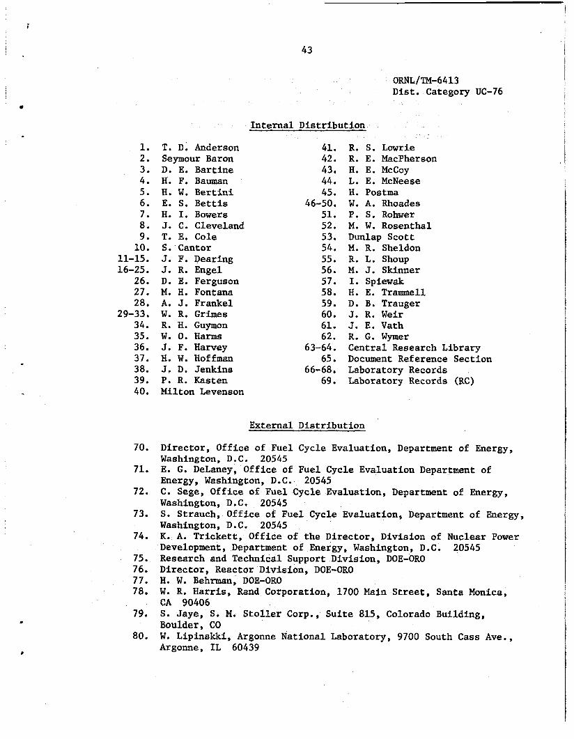
i
43
1. 2. 3. 4. 5 . 6. 7. 8. 9. 10.
11-15. 16-25.
26. 27. 28.
29-33. 34. 35. 36. 37. 38. 39. 40.
70.
71.
72.
73.
74.
75. 76. 77. 78.
79.
80.
ORNL/TM-6413 Dist. Category UC-76
Internal Distribution
T. D; Anderson 41. R. S. Lowrie Seymour Baron 42. R. E. MacPherson D. E. Bartine 43. H. E. McCoy H. F. Bauman 44. L. E. McNeese H. W. Bertini 45. H. Postma E. S. Bettis 46-50. W. A. Rhoades H. I. Bowers 51. P . S. Rohwer J. C. Cleveland 52. M. W. Rosenthal T. E. Cole 53. Dunlap Scott S. Cantor 54. M. R. Sheldon J. F. Pearing 55. R. L. Shoup J. R. Engel 56. M. J. Skinner D. E. Ferguson 57. I. Spiewak M. H. Fontana 58. H. E. Trammel1 A. J. Frankel 59. D. B. Trauger W. R. Grimes 60. J. R. Weir R. H. Guymon 61. J. E. Vath W. 0. Harms 62. R. G. Wymer J. F. Harvey 63-64. Central Research Library H. W. Hoffman 65. Document Reference Section J. D. Jenkins 66-68. Laboratory Records P. R. Kasten 69. Laboratory Records (RC) Milton Levenson
External Distribution
Director, Office of Fuel Cycle Evaluation, Department of Energy, Washington, D.C. 20545 E. G. DeLaney, Office of Fuel Cycle Evaluation Department of Energy, Washington, D.C. 20545 C. Sege, Office of Fuel Cycle Evaluation, Department of Energy, Washington, D. C . 20545 S. Strauch, Office of Fuel Cycle Evaluation, Department of Energy, Washington, D.C. 20545 K. A. Trickett, Office of the Director, Division of Nuclear Power Development, Department of Energy, Washington, D.C. 20545 Research and Technical Support Division, DOE-OR0 Director, Reactor Division, DOE-OR0 H. W. Behrman, DOE-OR0 W. R. Harris, Rand Corporation, 1700 Main Street, Sants Monica, CA 90406 S. Jaye, S. M. Stoller Corp., Suite 815, Colorado Building, Boulder, CO W. Lipinskki, Argonne National Laboratory, 9700 South Cass Ave., Argonne, IL 60439

44
81.
82.
R, Chnberg, Hanford Engineering Development Laboratory, P.O. Box 1970, Richland, WASH 99352' E. Straker, Science Applications, 8400 Westpark Drive, McLean, VA 22101 For distribution as shown in TID-4500 under category UC-76, 83-193, Molten-Salt Reactor Technology
I .
c
5
c