oracle hospitality simphony · create interface 3-1 ... test configuration 3-5 appendix a-ascii...
TRANSCRIPT
Oracle® Hospitality Simphony Property Management System Interface Reference
Release 18.2 F12084-01 December 2018
ii
Oracle Hospitality Simphony Property Management System Interface Reference, Release 18.2
F12084-01
Copyright © 2010, 2018, Oracle and/or its affiliates. All rights reserved.
This software and related documentation are provided under a license agreement containing restrictions on use and disclosure and are protected by intellectual property laws. Except as expressly permitted in your license agreement or allowed by law, you may not use, copy, reproduce, translate, broadcast, modify, license, transmit, distribute, exhibit, perform, publish, or display any part, in any form, or by any means. Reverse engineering, disassembly, or decompilation of this software, unless required by law for interoperability, is prohibited.
The information contained herein is subject to change without notice and is not warranted to be error-free. If you find any errors, please report them to us in writing.
If this software or related documentation is delivered to the U.S. Government or anyone licensing it on behalf of the U.S. Government, then the following notice is applicable:
U.S. GOVERNMENT END USERS: Oracle programs, including any operating system, integrated software, any programs installed on the hardware, and/or documentation, delivered to U.S. Government end users are "commercial computer software" pursuant to the applicable Federal Acquisition Regulation and agency-specific supplemental regulations. As such, use, duplication, disclosure, modification, and adaptation of the programs, including any operating system, integrated software, any programs installed on the hardware, and/or documentation, shall be subject to license terms and license restrictions applicable to the programs. No other rights are granted to the U.S. Government.
This software or hardware is developed for general use in a variety of information management applications. It is not developed or intended for use in any inherently dangerous applications, including applications that may create a risk of personal injury. If you use this software or hardware in dangerous applications, then you shall be responsible to take all appropriate fail-safe, backup, redundancy, and other measures to ensure its safe use. Oracle Corporation and its affiliates disclaim any liability for any damages caused by use of this software or hardware in dangerous applications.
Oracle and Java are registered trademarks of Oracle and/or its affiliates. Other names may be trademarks of their respective owners.
Intel and Intel Xeon are trademarks or registered trademarks of Intel Corporation. All SPARC trademarks are used under license and are trademarks or registered trademarks of SPARC International, Inc. AMD, Opteron, the AMD logo, and the AMD Opteron logo are trademarks or registered trademarks of Advanced Micro Devices. UNIX is a registered trademark of The Open Group.
This software or hardware and documentation may provide access to or information about content, products, and services from third parties. Oracle Corporation and its affiliates are not responsible for and expressly disclaim all warranties of any kind with respect to third-party content, products, and services unless otherwise set forth in an applicable agreement between you and Oracle. Oracle Corporation and its affiliates will not be responsible for any loss, costs, or damages incurred due to your access to or use of third-party content, products, or services, except as set forth in an applicable agreement between you and Oracle.
iii
Contents
Preface iv
1 PMS Interface Requirements 1-1
Communications Channel Characteristics 1-1 Serial Communications 1-1 Message Format 1-2 Link Control Characters 1-3 Message Processing Considerations 1-4 Message Data Block Field Types 1-5 Messages 1-8
2 Sample Messages 2-1
Computer Inquire Request Message 2-1 Computer Charge Posting Message 2-2
3 Configuring the PMS Interface 3-1
Create Interface 3-1 Configure Revenue Center Parameters to Link to Interface 3-2 Configure Tender Media to Associate with Interface 3-3 Configure PMS Buttons for POS Client Screens 3-4 Test Configuration 3-5
Appendix A - ASCII Control Codes A-1
Preface
iv
Preface
Purpose
This document contains information about designing an interface between Oracle
Hospitality Simphony and a Property Management System (PMS).
For the purposes of this document, the term POS is used as a generic term to refer to the
Simphony Point of Service (POS) System.
Simphony only supports a TCP/IP connection with the PMS. If Simphony needs to be
configured to talk to a PMS which has only a serial interface, a third-party solution for
converting TCP/IP to serial message must be employed. The most popular solutions are
hardware devices that have a single TCP/IP port and an RS-232 serial port. There are
also software-based solutions that have been used.
Audience
This document is intended for:
Programmers who design software interfaces between Simphony POS systems and
property management systems
Field engineers and technicians who troubleshoot problems with interfaces between
Simphony POS systems and property management systems
The following prerequisites are suggested:
Clear understanding of the charge posting specifications of the PMS interface being
programmed, and a thorough understanding of how to implement the interface
Understanding of how to program the specific product involved to enable the charge
posting interface
Abbreviations
Abbreviation Description
EMC Enterprise Management Console
OPS Simphony POS Operations Client
PMS Property Management System
POS Point-of-Service
RVC Revenue Center
Customer Support
To contact Oracle Customer Support, access My Oracle Support at the following URL:
https://support.oracle.com
Preface
v
When contacting Customer Support, please provide the following:
Product version and program/module name
Functional and technical description of the problem (include business impact)
Detailed step-by-step instructions to re-create
Exact error message received and any associated log files
Screenshots of each step you take
Documentation
Oracle Hospitality product documentation is available on the Oracle Help Center at
http://docs.oracle.com/en/industries/hospitality/
Revision History
Date Description of Change
December 2018 Initial publication
Chapter 1 PMS Interface Requirements
1-1
1
PMS Interface Requirements
This chapter explains the requirements of the PMS interface from the standpoint of
cabling, transmission characteristics, and basic message protocol.
Communications Channel Characteristics
Serial Communications
Message Format
Link Control Characters
Message Processing Considerations
Message Data Block Field Types
Messages
Communications Channel Characteristics
Simphony communicates with the PMS computer using a TCP/IP communications
interface. Depending on the PMS computer, it may be necessary to employ the use of a
TCP/IP to serial converter solution (either hardware or software) to communicate the
PMS messages between the systems.
The message format used by Simphony is the same format that has been used by
previous generations of products to ensure backward compatibility with existing PMS
solutions.
Serial Communications
Although Simphony can only be configured to communicate with a TCP/IP based end
point, some PMS solutions still only support serial based interfaces. For those systems, it
is necessary to communicate with some middleware, and the following settings need to
be configured correctly so that the PMS and middleware can communicate:
Transmission Mode: The transmission mode over the RS 232C communications
channel is asynchronous, serial binary, and full duplex.
Baud Rate: The transmission baud rate can be selected (if the POS system and the
PMS computer agree) as 300, 600, 1200, 2400, 4800, or 9600 baud.
Character Format: The transmission character format can be selected, if the POS
System and the PMS Computer agree. The character type is 7-bit ASCII (or 8-bit for
international characters); the character length can be set at 7 or 8 bits with an even,
odd, or no parity bit. Each character will include a single start bit and 1 or 2 stop bits
for character framing.
Chapter 1 PMS Interface Requirements
1-2
Line Connection: The POS System can interface to the PMS computer using an EIA
standard RS232C D-type female connector, either 9 or 25 pin at the POS. The PMS
computer can connect to the POS system directly (hard-wired) or through
asynchronous short-haul modems to overcome possible line distance limitations. The
following tables describe the pin-outs for the alternatives. Refer to the PMS
documentation for guidance about the specific pin-outs at the PMS computer.
NOTE:
The CTS signal must be True to enable the POS system to transmit data to the PMS computer. The DSR and DCD signals must both be True to enable the POS system to receive data from the PMS computer.
Refer to the third-party documentation for information on the pin-outs that are used
on that solution.
Message Format
The format of all messages initiated by the POS system and the PMS computer has the
following form:
SOH <ID> STX <DATA> ETX <CKSUM> EOT
The following are descriptions of the individual message components:
SOH The SOH character (start of header) is a message lead-in character that identifies the start of a new message. The SOH character is represented by the 7-bit hexadecimal value 01 (or Hex 01), plus a parity bit if applicable.
<ID> The <ID> character field identifies the source (when sent by the POS system) and the destination of a message (when sent by the PMS computer). The field contains 18 characters: the User Workstation or System Unit Number (2 characters) followed by the Comms System Name (16 characters).
The User Workstation or System Unit Number is a 2 byte numeric character field in the range 1 through 99. It is represented by ASCII character codes in the range Hex 30 through Hex 39, plus parity bits, if applicable. This field is represented by a U2 type format. (Message Data Block Field Types on page 1-5 provides more information on type formats.)
In Simphony a UWS can have a number up to 999999999, but only the last 2 digits are transmitted.
The Comms System Name (formerly called the POS System Name) or Outgoing Message Name is a 16 byte alphanumeric character field stored in the PMS Definition File <EMC MODULE CORRECTION>. This field is represented by ASCII character codes, plus parity bits, if applicable. It identifies and differentiates the source(s) of the
Chapter 1 PMS Interface Requirements
1-3
communications message(s) if more than one system is posting to the PMS computer.
STX The STX character (start of text) is a data field lead-in character that identifies the start of the message data block. The STX character is represented by the 7-bit hexadecimal value 02, plus a parity bit, if applicable.
<DATA> The <DATA> field contains the message data block and is represented by ASCII character codes in the range Hex 20 through Hex 7F, plus parity bits, if applicable. The length of the <DATA> field is variable and is determined by each individual message.
ETX The ETX (end of text) character serves as a data field lead-out character that identifies the end of the message data block. The ETX character is represented by the 7-bit hexadecimal value 03, plus a parity bit, if applicable.
<CKSUM> The <CKSUM> field contains the checksum characters of the message. This field is 4 numeric ASCII-HEX characters represented by the ASCII character codes in the range Hex 30 through Hex 39 (0 through 9) and Hex 41 through Hex 46 (A through F), plus parity bits, if applicable. The <CKSUM> field always follows the ETX character.
The checksum (initially set to zero) is a 16-bit binary addition (excluding parity bits, if applicable) of all characters after, but not including, the SOH character and through, including, the ETX character. The checksum accumulation is then encoded into the "equivalent" ASCII-HEX character representations (plus parity bits, if applicable) so that the <CKSUM> field is suitable for transmission over the communications channel.
For example, if the resulting 16-bit checksum has the hexadecimal value of D2B9, it would be encoded into ASCII characters "D" (Hex 44), "2" (Hex 32), "B" (Hex 42), and "9" (Hex 39) with the character "D" transmitted first.
EOT The EOT (end of transmission) character serves as a message lead-out character and identifies the end of a message. The EOT character is represented by the 7-bit hexadecimal value 04, plus a parity bit, if applicable.
Link Control Characters
Link control characters are used by the recipient of a message to manage the transfer of
messages over the communications line and to provide for reliable exchange of
information. The following paragraphs describe link control characters used to manage
the flow of messages over the communications channel.
ACK The ACK (acknowledgment) character is a positive acknowledgment to a received message. It indicates the successful receipt of a message (with no framing, parity, overrun, or block check code errors detected). The ACK character is represented by the 7-bit hexadecimal value 06, plus a parity bit, if applicable.
NOTE The positive acknowledgment character does not imply the proper context or formatting of a <DATA> field for a particular message. It
Chapter 1 PMS Interface Requirements
1-4
merely implies that the overall message format met the protocol requirements for reliable data exchange over the communications channel.
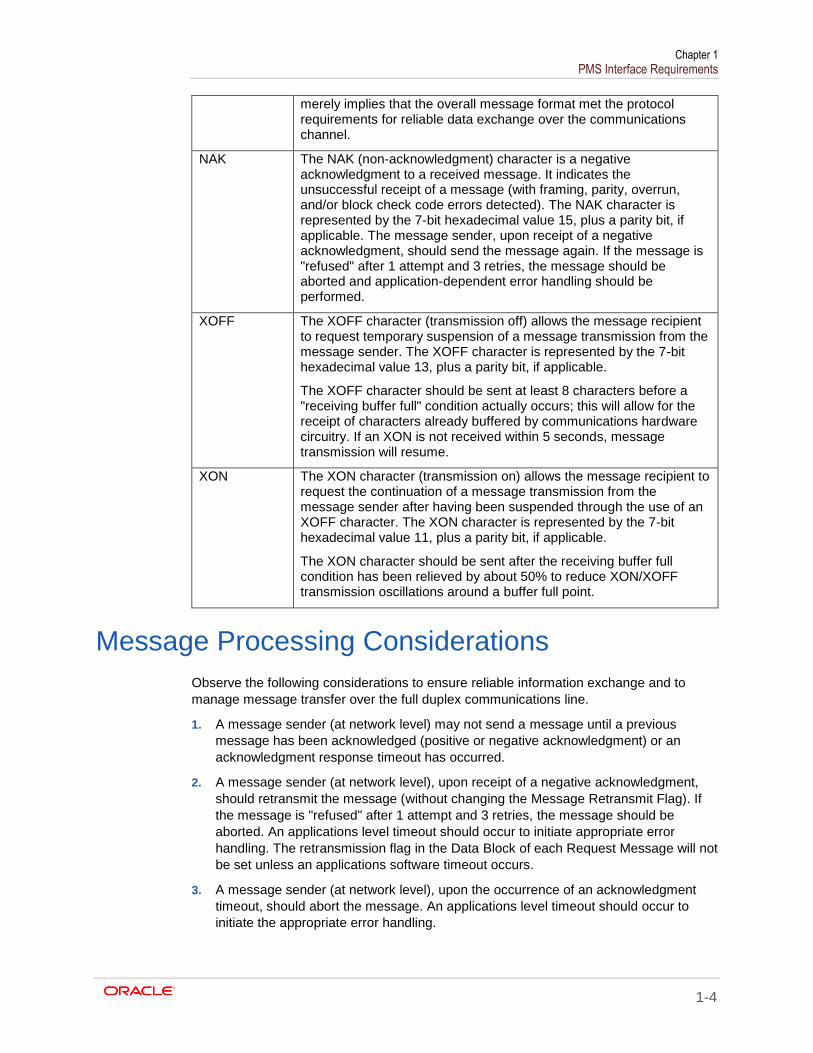
NAK The NAK (non-acknowledgment) character is a negative acknowledgment to a received message. It indicates the unsuccessful receipt of a message (with framing, parity, overrun, and/or block check code errors detected). The NAK character is represented by the 7-bit hexadecimal value 15, plus a parity bit, if applicable. The message sender, upon receipt of a negative acknowledgment, should send the message again. If the message is "refused" after 1 attempt and 3 retries, the message should be aborted and application-dependent error handling should be performed.
XOFF The XOFF character (transmission off) allows the message recipient to request temporary suspension of a message transmission from the message sender. The XOFF character is represented by the 7-bit hexadecimal value 13, plus a parity bit, if applicable.
The XOFF character should be sent at least 8 characters before a "receiving buffer full" condition actually occurs; this will allow for the receipt of characters already buffered by communications hardware circuitry. If an XON is not received within 5 seconds, message transmission will resume.
XON The XON character (transmission on) allows the message recipient to request the continuation of a message transmission from the message sender after having been suspended through the use of an XOFF character. The XON character is represented by the 7-bit hexadecimal value 11, plus a parity bit, if applicable.
The XON character should be sent after the receiving buffer full condition has been relieved by about 50% to reduce XON/XOFF transmission oscillations around a buffer full point.
Message Processing Considerations
Observe the following considerations to ensure reliable information exchange and to
manage message transfer over the full duplex communications line.
1. A message sender (at network level) may not send a message until a previous
message has been acknowledged (positive or negative acknowledgment) or an
acknowledgment response timeout has occurred.
2. A message sender (at network level), upon receipt of a negative acknowledgment,
should retransmit the message (without changing the Message Retransmit Flag). If
the message is "refused" after 1 attempt and 3 retries, the message should be
aborted. An applications level timeout should occur to initiate appropriate error
handling. The retransmission flag in the Data Block of each Request Message will not
be set unless an applications software timeout occurs.
3. A message sender (at network level), upon the occurrence of an acknowledgment
timeout, should abort the message. An applications level timeout should occur to
initiate the appropriate error handling.
Chapter 1 PMS Interface Requirements
1-5
4. A message sender (at network level) should wait 5 seconds for a message
acknowledgment before aborting the message (acknowledgment timeout).
5. The applications level timeout at the PMS Computer should be 30 to 45 seconds
before initiating an error handling procedure. The applications level timeout at the
POS System is programmable between 0 and 255 seconds.
6. Network level communications handling processing should initialize in the XON
condition.
7. To avoid a possible "hung" transmission line condition after the receipt of an XOFF
character, a 5 second timeout should be used to continue transmission in the
absence of a received XON character (at network level).
8. Due to the nature of full duplex communications, it is possible that link control
characters (ACK, NAK, XON, and XOFF) will be interspersed within data messages.
The message receiver interface (network level) must screen all incoming characters
to determine if the character is a link control character (to gate the character to link
control processing) or a data message character (to gate the character to message
accumulation processing).
Message Data Block Field Types
Message data block field types for both request and response messages are detailed in
terms of field description, field size, and field format. The field description identifies the
way in which the data is interpreted (such as employee number, revenue center number,
and so on). The field size indicates the number of ASCII characters that are in the given
field. The field format describes the field in terms of data type.
The following is a description of the five basic field format data types:
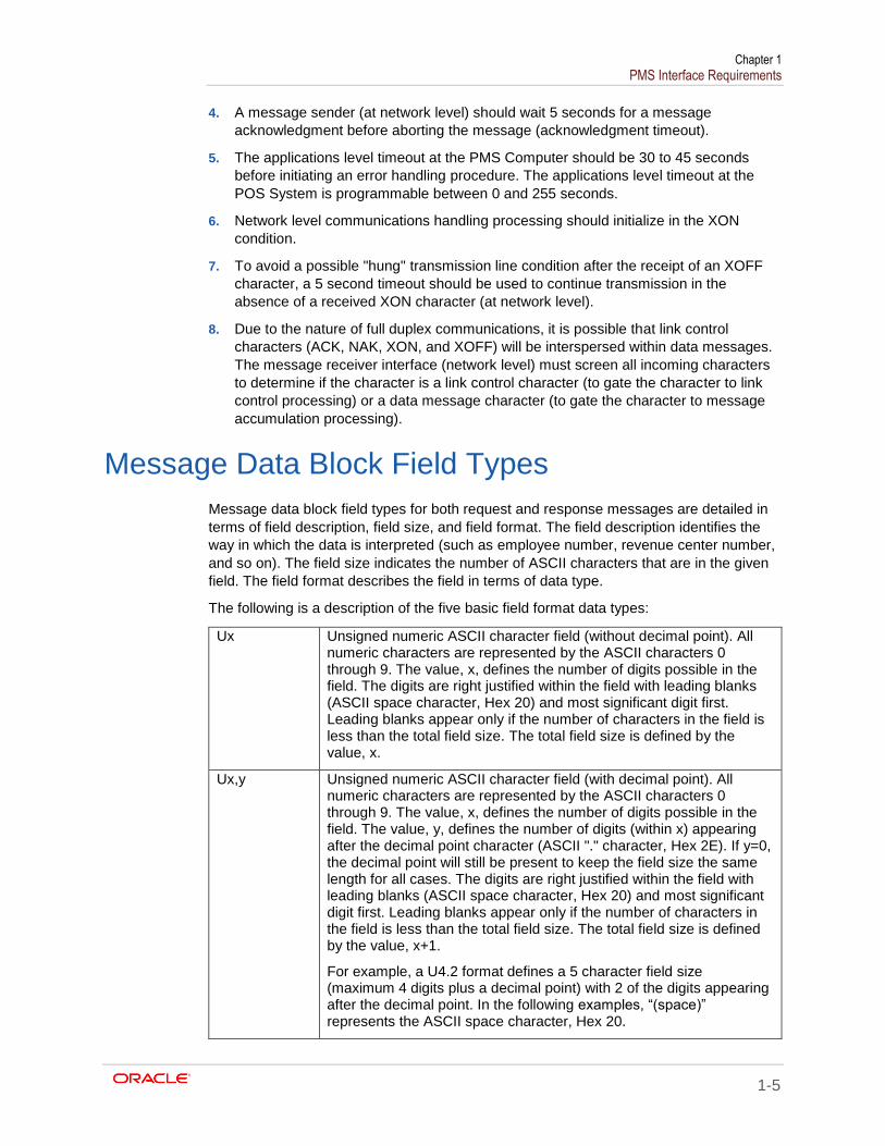
Ux Unsigned numeric ASCII character field (without decimal point). All numeric characters are represented by the ASCII characters 0 through 9. The value, x, defines the number of digits possible in the field. The digits are right justified within the field with leading blanks (ASCII space character, Hex 20) and most significant digit first. Leading blanks appear only if the number of characters in the field is less than the total field size. The total field size is defined by the value, x.
Ux,y Unsigned numeric ASCII character field (with decimal point). All numeric characters are represented by the ASCII characters 0 through 9. The value, x, defines the number of digits possible in the field. The value, y, defines the number of digits (within x) appearing after the decimal point character (ASCII "." character, Hex 2E). If y=0, the decimal point will still be present to keep the field size the same length for all cases. The digits are right justified within the field with leading blanks (ASCII space character, Hex 20) and most significant digit first. Leading blanks appear only if the number of characters in the field is less than the total field size. The total field size is defined by the value, x+1.
For example, a U4.2 format defines a 5 character field size (maximum 4 digits plus a decimal point) with 2 of the digits appearing after the decimal point. In the following examples, “(space)” represents the ASCII space character, Hex 20.
Chapter 1 PMS Interface Requirements
1-6
12.34 (space)1.23 (space)(space).12
(space)(space).01 (space)(space).00
The same example with a U4.0 format would appear as follows:
1234. (space)123. (space)(space)12.
(space)(space)(space)1. (space)(space)(space)0.
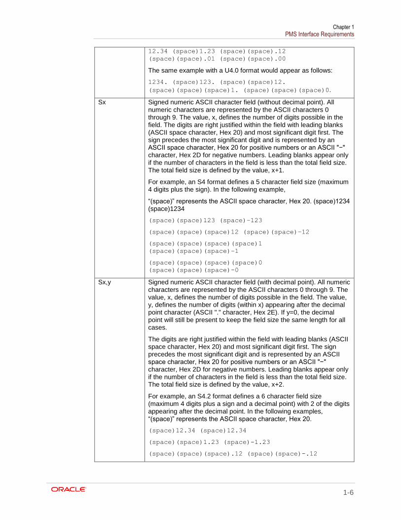
Sx Signed numeric ASCII character field (without decimal point). All numeric characters are represented by the ASCII characters 0 through 9. The value, x, defines the number of digits possible in the field. The digits are right justified within the field with leading blanks (ASCII space character, Hex 20) and most significant digit first. The sign precedes the most significant digit and is represented by an ASCII space character, Hex 20 for positive numbers or an ASCII "−" character, Hex 2D for negative numbers. Leading blanks appear only if the number of characters in the field is less than the total field size. The total field size is defined by the value, x+1.
For example, an S4 format defines a 5 character field size (maximum 4 digits plus the sign). In the following example,
“(space)” represents the ASCII space character, Hex 20. (space)1234 (space)1234
(space)(space)123 (space)−123
(space)(space)(space)12 (space)(space)−12
(space)(space)(space)(space)1
(space)(space)(space)−1
(space)(space)(space)(space)0
(space)(space)(space)−0
Sx,y Signed numeric ASCII character field (with decimal point). All numeric characters are represented by the ASCII characters 0 through 9. The value, x, defines the number of digits possible in the field. The value, y, defines the number of digits (within x) appearing after the decimal point character (ASCII "." character, Hex 2E). If y=0, the decimal point will still be present to keep the field size the same length for all cases.
The digits are right justified within the field with leading blanks (ASCII space character, Hex 20) and most significant digit first. The sign precedes the most significant digit and is represented by an ASCII space character, Hex 20 for positive numbers or an ASCII "−" character, Hex 2D for negative numbers. Leading blanks appear only if the number of characters in the field is less than the total field size. The total field size is defined by the value, x+2.
For example, an S4.2 format defines a 6 character field size (maximum 4 digits plus a sign and a decimal point) with 2 of the digits appearing after the decimal point. In the following examples, “(space)” represents the ASCII space character, Hex 20.
(space)12.34 (space)12.34
(space)(space)1.23 (space)-1.23
(space)(space)(space).12 (space)(space)-.12
Chapter 1 PMS Interface Requirements
1-7
(space)(space)(space).01 (space)(space)-.01
(space)(space)(space).00 (space)(space)-.00
The same example, but with an S4.0 format, appears as follows:
(space)1234. (space)1234
(space)(space)123. (space)-123
(space)(space)(space)12. (space)(space)-12
(space)(space)(space)(space)1.
(space)(space)(space)-1
(space)(space)(space)(space)0.
(space)(space)(space)-0
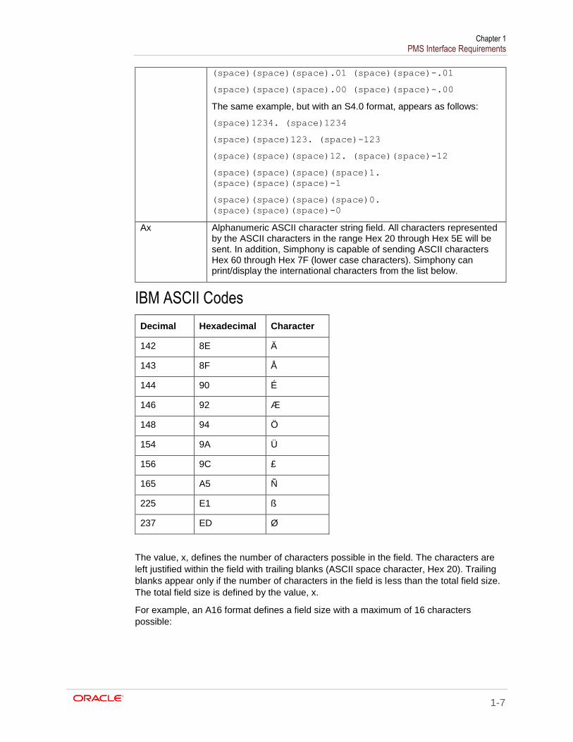
Ax Alphanumeric ASCII character string field. All characters represented by the ASCII characters in the range Hex 20 through Hex 5E will be sent. In addition, Simphony is capable of sending ASCII characters Hex 60 through Hex 7F (lower case characters). Simphony can print/display the international characters from the list below.
IBM ASCII Codes
Decimal Hexadecimal Character
142 8E Ä
143 8F Å
144 90 É
146 92 Æ
148 94 Ö
154 9A Ü
156 9C £
165 A5 Ñ
225 E1 ß
237 ED Ø
The value, x, defines the number of characters possible in the field. The characters are
left justified within the field with trailing blanks (ASCII space character, Hex 20). Trailing
blanks appear only if the number of characters in the field is less than the total field size.
The total field size is defined by the value, x.
For example, an A16 format defines a field size with a maximum of 16 characters
possible:
Chapter 1 PMS Interface Requirements
1-8
Character Position
1 2 3 4 5 6 7 8 9 10 11 12 13 14 15 16
Example 1
I N V A L I D A C C T #
Messages
This section provides details about the contents of the data blocks sent through the PMS
interface.
Computer Inquire Request Message
The Computer Inquire Request Message is sent by the POS system to request the return
of information from an on-line PMS computer in real-time.
Message Data Block Format Number of Characters Field Type
Message Type (1) 2 U2
Message Retransmit Flag 1 A1
Account ID Information 16 (19) A16 (A19)
Employee Number 4 U4
Total 23 or 26
Total depends on the Account ID field.
The following is a description of the fields in the message data block of the Computer
Inquire Request Message:
Message Type
This field will be set to (space)1 (a space followed by 1, ASCII characters with Hex values 20 and 31) to identify a Computer Inquire Request Message.
Message Retransmit Flag
This field will be set to (space) (one space, 20, or Hex 20) for all initial Computer Inquire Request messages. This field will be set to R (Hex 52) to identify the applications-level retransmission of a previously sent Computer Inquire Request message (not a network-level retransmission).
Account ID Information
This field is entered by the POS operator and generally contains any information necessary to identify the nature of the computer inquiry, such as an account number. The field contents and syntax are defined and interpreted by the PMS Computer. The POS system does not perform any edit checking of this field
The Inquire key can send an Inquiry Message string that is either 16 or 19 digits long, based on the configuration of option bit 1 (Use 19 Digit Reference Entry for PMS Inquires) for the PMS interface record.
Employee Number
This field identifies the employee who performed the computer inquiry transaction. The valid employee number range is 1 through 9999. Employee Number 0 will be sent if no employee is signed in at the time the Inquire key is used.
Chapter 1 PMS Interface Requirements
1-9
This field can be up to 999999999 but only the last four digits will be transmitted.
Computer Inquire Response Message
The Computer Inquire Response Message is sent by the PMS computer to supply
information in response to an information request from an on-line POS system (in the
form of a Computer Inquire Request Message) in real-time.
Message Data Block Format Number of Characters Field Type
Message Type (1) 2 U2
Information Message 2 (optional) 16 A16
Information Message 3 (optional) 16 A16
Information Message 4 (optional) 16 A16
Information Message 5 (optional) 16 A16
Information Message 6 (optional) 16 A16
Information Message 7 (optional) 16 A16
Information Message 8 (optional) 16 A16
Total 130
The following is a description of the fields in the message data block of the Computer
Inquire Response Message:
Message Type
This field must be set to (space)1 (a space followed by 1, ASCII characters with Hex values 20 and 31) to identify a Computer Inquire Response Message.
Information Messages 1-8
These fields are used by the PMS Computer to supply information to the POS operator to satisfy the computer inquiry request. The POS System presents these fields to the POS display for POS operator review. Each field is limited to a total of 16 characters each; likewise, if you want the folios or account names to appear on different lines at the POS System, you must pad each message line out to 16 characters.
Outlet Charge Posting Request Message The Outlet Charge Posting Request Message is sent by the POS system to post outlet
charges to an on-line PMS computer in real-time.
Message Data Block Format Number of Characters Field Type
Message Type (2) 2 U2
Message Retransmit Flag 1 A1
Account ID Information (2 choices): 16 or 19 digits
16 (19) A16 (A19)
Expiration Date (mmyy) 4 U4
Chapter 1 PMS Interface Requirements
1-10
Message Data Block Format Number of Characters Field Type
Selection Field Information 16 A16
Selection Field Number 1 U1
Transaction Employee Number 4 U4
Check/Order Employee Number 4 U4
Store/Revenue Center Number (2 choices):
3 or 5 digits
3 (5) U3 (U5)
Serving Period Number 3 U3
Guest Check 4 (up to 8)1 U4
Transaction Number 4 U4
Number of Covers/Guests/Customers (2 choices): 4 or 5 digits
4 (5) S3 (S4)
Current Payment Number 3 U3
Current Payment Amount 10 S8.y
Sales 1 Total 10 S8.y
Sales 2 Total 10 S8.y
Sales 3 Total 10 S8.y
Sales 4 Total 10 S8.y
Discount Total 10 S8.y
Service Charge Total, keyboard entered
10 S8.y
Service Charge Total, automatic 10 S8.y
Tax 1 Total (or VAT 1 Gross Total) 10 S8.y
Tax 2 Total (or VAT 2 Gross Total) 10 S8.y
Tax 3 Total (or VAT 3 Gross Total) 10 S8.y
Tax 4 Total (or VAT 4 Gross Total) 10 S8.y
Previous Payment Total 10 S8.y
Total 199, 200, 202 or 203
The decimal fields displayed above all have the format S8.y, which means that these fields contain up to 8 digits, regardless of the placement of the decimal point (actually, up to 10 characters are transmitted, including the decimal point and sign (for example, -
1 Based on enabling option 11 - On = Use 8-digit Check #; Off = Use 4-digit Check #, located in the EMC, Setup tab, Interfaces, Options tab, a check number could be eight digits long. If this option is enabled, integrated logic must be introduced to handle eight digit check numbers.
Chapter 1 PMS Interface Requirements
1-11
1234567.8 or 12345.678); the number of digits after the decimal (y) may be set to 0, 1, 2, or 3.
The following is a description of the fields in the message data block of the Outlet Charge
Posting Request Message:
Message Type This field will be set to (space) 2 (a space followed by 2, ASCII characters with Hex values 20 and 32) to identify an Outlet Charge Posting Request Message.
Message Retransmit Flag
This field will be set to (space) (one space, Hex 20) for all initial Outlet Charge Posting Request messages. This field will be set to R (Hex 52) to identify the retransmission of a previously sent Outlet Charge Posting Request message.
Account ID Information
This field, entered by the POS operator, generally contains the posting account number and any other information necessary to identify the posting account. The field content and syntax is defined and interpreted by the PMS computer. The POS system does not perform edit checking of this field. If this message is being forwarded back to the PMS computer as the result of a "list" selection (see Outlet Charge Posting Response Message), this field will still contain the original information entered by the POS operator. The size of the field is defined by the POS system, and either a 16 or 19 digit entry can be used. The programming of this option is configured in the Tender Media record (option #31).
See also the definition of the Account ID Information field for the Computer Inquire Request Message.
Expiration Date
This field is entered by the POS operator (manually or through a magnetic card reader); it contains the expiration date of a credit card in the form mmyy. This field only pertains to credit card postings (the field contains zero for all non-credit card postings). The Account ID Information field will contain the credit card number.
This field is used to support positive posting account identification applications. If this message is being forwarded back to the PMS computer as the result of a "list" selection (see Outlet Charge Posting Response Message), this field will contain the POS operator’s choice, selected from the list provided in the Response Message. This field will be a (space) (Hex 20) for all "initial" issue Outlet Charge Posting Request messages.
Selection Field Number
This field is used to support positive posting account identification applications. If this message is being forwarded back to the PMS Computer as the result of a "list" selection (see Outlet Charge Posting Response Message), this field will contain the position number of the field selected by the POS operator that was supplied by the PMS Computer in a previous Posting Response Message. The possible selection field number range is 1 through 8. This field will be set to 0 (Hex 30) for all "initial" issue Outlet Charge Posting Request messages.
Transaction Employee Number
This field identifies the Transaction Employee who posted the outlet charge (for example, cashier, or manager). Transaction and Check/Order Employees may be different. The range of possible
Chapter 1 PMS Interface Requirements
1-12
Employee Numbers is 1 through 999999999 but only the last four digits are transmitted.
Check/Order Employee Number
This field identifies the Check/Order Employee responsible for the guest check. The Transaction and Check/Order Employees may be different. The range of possible Employee Numbers is 1 through 999999999 but only the last four digits are transmitted.
Store/Revenue Center Number
This field identifies the Revenue Center (RVC) Number of the outlet from which the charge originated. Simphony can use either a 3 or 5 digit RVC number (Interface Record – option bit #10). Older PMS systems will most likely only support a three RVC number. If a 3 digit number is used, Simphony will transmit the last 3 digits of the RVC number.
Serving Period Number
This field identifies the Serving Period Number that is active when the charge is posted. This field can be up to 999999999 but only the last three digits will be transmitted.
Guest Check This field identifies the guest check number of the check being settled (in partial or whole) by the charge posting.
Transaction Number
This field is not used by Simphony and is always set to 0.
Number of Guests
This field identifies the number of guests/customers recorded on the guest check or order. The range for this field is 1 through 9999 (if positive) or -9999 (if negative). If Interface record option 4 (use 5 Digits for Number of Guests) is enabled, the range will be 99999 to -99999.
Current Payment Number
This field identifies the Tender/Media Number assigned to the payment key through which the charge is being posted. The valid range is 1 – 999. Simphony supports values up to 999999999 for the tender media record number. Only the last three digits are sent.
Current Payment Amount
This field identifies the actual amount being posted to the PMS. This amount may represent either a payment-in-full towards the transaction or a partial payment amount (as in the case of a split tender transaction). In all products, there is an option to post either the payment-in-full or the total amount tendered, depending on the state of Interface record option 32.
The following totals represent either the entire guest check or the current transaction, depending on whether you have chosen to prorate the totals or not. After the definition of the last total (Previous Payment Total), you will find a complete definition of the non-prorated versus prorated distribution of these totals.
Sales Totals 1 through 4
These fields identify the breakdown of the sales item amounts for the transaction and may represent such breakdowns as food, liquor, beer, wine, and so on in Full Service products, depending on the POS system’s Menu Item File programming. This total is net of Item Discounts. When Value Added Tax (VAT) or US-inclusive tax is enabled, each total represents the total sales amount (inclusive of tax) for each of the chosen categories.
There are 16 Sales Totals itemizers; only the first four will be sent.
Chapter 1 PMS Interface Requirements
1-13
Discount Total This field identifies the total amount of any discounts taken against the transaction sales total amount.
Service Charge Total (kydb)
This field identifies the total amount of add-on amounts to the transaction total such as tips, cover charges, large group service charge, and so on that is not normally included in the sales total breakdown.
Service Charge Total (auto)
This field identifies the total amount of any automatic percentage add-on amounts to the transaction total such as an automatic service charge or gratuity that is not normally included in the sales total breakdown.
Tax Totals 1 through 4
These fields identify the breakdown of the transaction tax amounts for up to 4 different tax rates and/or tax categories. When Value Added Tax (VAT) is enabled, these totals represent the total sales amounts (inclusive of VAT) for each of the VAT categories. The tax must be calculated at the PMS. When US-inclusive tax is enabled, the total associated with each rate will be zero (0).
Previous Payment Total
This field identifies previous amounts paid against the transaction total exclusive of the amount being posted.
Programmer’s Note
The PMS interface can operate in one of two modes: non-prorated (traditional) or
prorated. In non-prorated mode, the values in the totals fields reflect the entire guest
check. In prorated mode, the totals fields only reflect the prorated amounts attributable to
the Current Payment Amount field’s share of the guest check
When reading the formulas presented below for non-prorated and prorated guest check
totals, keep in mind these points:
The first arithmetic operator indicates the operation that the PMS should perform on
the total field. The second arithmetic operator (in parentheses) indicates the normal
sign of the total field as presented in the message data block by the POS system.
If Value Added Tax (VAT) is being used, the tax totals represent the total sales
amounts (inclusive of VAT) for each of the VAT categories and MUST NOT be
included in the Transaction Total or Current Payment Total equations.
In non-prorated mode, if the Current Payment Amount field in the message data
block is less than the computed Transaction Total (above), a partial amount has been
tendered.
If the US-inclusive tax method is used, the tax total associated with this rate will be
zero.
Non-Prorated Guest Check Totals
In this mode, the totals reflect the entire guest check. Partial or voided payments do not
affect the value or polarity of these totals. If partial payments are required, it is the
responsibility of the PMS to prorate each total, as necessary.
The following equations can be used by the PMS computer to determine the Transaction
Total and the Total Amount Due of the transaction being posted:
Transaction Total = +
(+) Sales 1 Total
Chapter 1 PMS Interface Requirements
1-14
(+) Sales 2 Total
(+) Sales 3 Total
(+) Sales 4 Total
(-) Discount Total
(+) Service Charge Total (kybd)
(+) Service Charge Total (auto)
(+) Tax 1 Total (if non-VAT)
(+) Tax 2 Total (if non-VAT)
(+) Tax 3 Total (if non-VAT)
(+) Tax 4 Total (if non-VAT)
Total Amount Due = + (+) Transaction Total - (+) Previous Payment Total
The prorated mode is useful if the PMS is posting sales, discounts, tax, and so on during
the charge posting operation. When prorated totals are used, the totals reflect the Current
Payment’s share of a guest check. If the Current Payment is voided, the totals will have
the reversed polarity to reflect this. The only exception (the total that is not prorated) is
the charged tip, which will always be completely attributed to its associated payment.
The following equations can be used by the PMS computer to determine the Current
Payment Total of the prorated transaction being posted:
Current Payment Total = +
(+) Sales 1 Total
(+) Sales 2 Total
(+) Sales 3 Total
(+) Sales 4 Total
(-) Discount Total
(+) Service Charge Total (kybd)
(+) Service Charge Total (auto)
(+) Tax 1 Total (if non-VAT)
(+) Tax 2 Total (if non-VAT)
(+) Tax 3 Total (if non-VAT)
(+) Tax 4 Total (if non-VAT)
The Previous Payment Total is also provided.
In some jurisdictions, the prorated calculations will result in inexact tax totals. This occurs
because of rounding errors associated with proration and the methods required to
compute tax. For example, consider three guests paying a $10.00 check which includes
$1.00 tax. The first two guests will be charged $0.33 tax and the third $0.34 tax (the
rounding adjustment is included in the last total).
These situations are unavoidable; if complete accuracy is required, a Split Check
operation should be performed and the resultant checks individually posted to the PMS.
Chapter 1 PMS Interface Requirements
1-15
Outlet Charge Posting Response Message
The Outlet Charge Posting Response Message is sent by the PMS computer to accept,
deny, or request further information about an outlet charge posting from an on-line POS
system (in the form of an Outlet Charge Posting Request Message) in real-time.
Message Data Block Format Number of Characters Field Type
Message Type (2) 2 U2
Acceptance/Denial Message 16 A16
Selection Field Information, Select 1 (optional)
16 A16
Selection Field Information, Select 2 (optional)
16 A16
Selection Field Information, Select 3 (optional)
16 A16
Selection Field Information, Select 4 (optional)
16 A16
Selection Field Information, Select 5 (optional)
16 A16
Selection Field Information, Select 6 (optional)
16 A16
Selection Field Information, Select 7 (optional)
16 A16
Selection Field Information, Select 8 (optional)
16 A16
Total 146
The following is a description of the fields in the message data block of the Outlet Charge
Posting Response Message.
Message Type This field must be set to (space) 2 (ASCII characters with Hex values 20 and 32) to identify an Outlet Charge Posting Response Message.
Acceptance/Denial Message
This field tells the POS system if an attempted charge posting has been accepted or denied, or if positive account identification is needed from the POS operator to post the requested charge. This field is limited to a total of 16 characters; any unused character positions should be padded with trailing space characters.
To accept a charge posting: A charge posting is accepted by the PMS computer by putting any character other than "/" or "?" in the first character position of the field. The contents of this field will be printed along with the charge posting amount and settlement key name on the POS printer; it will generally contain the account number and/or account name to identify the posted account on the charge posting receipt.
Chapter 1 PMS Interface Requirements
1-16
To deny a charge posting: A charge posting is denied by the PMS computer by placing the "/" character in the first character position of the field. This message is presented to the POS operator in the POS display to identify the reason the charge posting was not accepted (for example, /INVALID ENTRY, / INVALID ACCT #, /VACANT ROOM). The POS operator may attempt to post the charge again (to correct a previous Account ID Information field entry error) at his/her option.
To request positive posting account identification: The PMS computer can request positive posting account identification from the POS operator by placing a "?" character in the first character position of the field (the rest of the field is ignored by the POS system but should be padded with trailing space characters).
The "?" character tells the POS system that up to 8 selection information fields have been supplied in the message data block. The POS system presents these fields to the POS operator for positive account posting identification and selection. These fields may represent a list of names in a room share situation in a hotel front desk charge posting application.
If the POS operator elects not to select any of the returned fields, the operation can be aborted. If the POS operator selects one of the returned fields, the POS system will supply the selected field (exactly as it was formatted by the PMS computer) in the Selection Field Information field of a new Outlet Charge Posting Request Message along with the position number of the field in the Selection Field Number field of the new request message. (All other fields in the request message will be the same as the previous message.)
Selection Field Information, Select 1 – 8
These fields are used by the PMS computer to request positive posting account identification by the POS operator when a "?" is returned in the Acceptance/Denial Message field (see above). These fields are limited to a total of 16 characters each; any unused character positions in each field should be padded with trailing space characters. Up to 8 of these fields may be returned in the message data block of the response message. These fields generally contain information necessary to positively identify the posting account(s). The POS system will supply the field selected by the POS operator (exactly as it was formatted by the PMS Computer) in the Selection Field Information field of the new request message (all other fields in the request message will be the same as the previous message). The presence of any information selection fields will be ignored by the POS system if a "?" is not returned in the Acceptance/Denial Message field.
Chapter 2 Sample Messages
2-1
2
Sample Messages
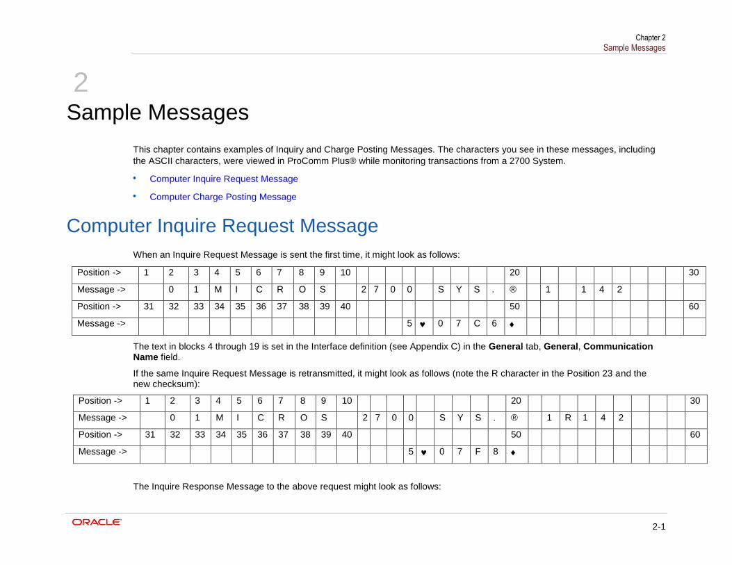
This chapter contains examples of Inquiry and Charge Posting Messages. The characters you see in these messages, including
the ASCII characters, were viewed in ProComm Plus® while monitoring transactions from a 2700 System.
Computer Inquire Request Message
Computer Charge Posting Message
Computer Inquire Request Message
When an Inquire Request Message is sent the first time, it might look as follows:
Position -> 1 2 3 4 5 6 7 8 9 10 20 30
Message -> 0 1 M I C R O S 2 7 0 0 S Y S . ® 1 1 4 2
Position -> 31 32 33 34 35 36 37 38 39 40 50 60
Message -> 5 0 7 C 6
The text in blocks 4 through 19 is set in the Interface definition (see Appendix C) in the General tab, General, Communication Name field.
If the same Inquire Request Message is retransmitted, it might look as follows (note the R character in the Position 23 and the new checksum):
Position -> 1 2 3 4 5 6 7 8 9 10 20 30
Message -> 0 1 M I C R O S 2 7 0 0 S Y S . ® 1 R 1 4 2
Position -> 31 32 33 34 35 36 37 38 39 40 50 60
Message -> 5 0 7 F 8
The Inquire Response Message to the above request might look as follows:
Chapter 2 Sample Messages
2-2
Position -> 1 2 3 4 5 6 7 8 9 10 20 30
Message -> 0 1 M I C R O S 2 7 0 0 S Y S . ® 1 A D A M S , S
Position -> 31 32 33 34 35 36 37 38 39 40 50 60
Message -> T A C E Y 0 8 9 5 ♠
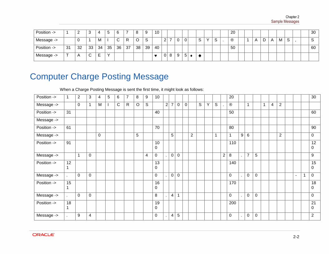
Computer Charge Posting Message
When a Charge Posting Message is sent the first time, it might look as follows:
Position -> 1 2 3 4 5 6 7 8 9 10 20 30
Message -> 0 1 M I C R O S 2 7 0 0 S Y S . ® 1 1 4 2
Position -> 31 40 50 60
Message ->
Position -> 61 70 80 90
Message -> 0 5 5 2 1 1 9 6 2 0
Position -> 91 100
110 120
Message -> 1 0 4 0 . 0 0 2 8 . 7 5 9
Position -> 121
130
140 150
Message -> . 0 0 0 . 0 0 0 . 0 0 - 1 0
Position -> 151
160
170 180
Message -> . 0 0 8 . 4 1 0 . 0 0 0
Position -> 181
190
200 210
Message -> . 9 4 0 . 4 5 0 . 0 0 2
Chapter 2 Sample Messages
2-3
Position -> 211
220
230 240
Message -> . 4 5 0 . 0 0 2 2 A 7
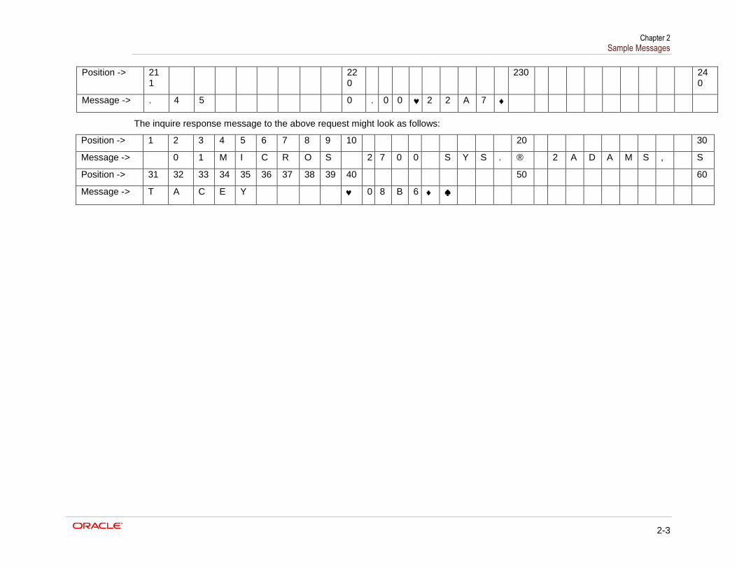
The inquire response message to the above request might look as follows:
Position -> 1 2 3 4 5 6 7 8 9 10 20 30
Message -> 0 1 M I C R O S 2 7 0 0 S Y S . ® 2 A D A M S , S
Position -> 31 32 33 34 35 36 37 38 39 40 50 60
Message -> T A C E Y 0 8 B 6 ♠
Chapter 3 Configuring the PMS Interface
3-1
3
Configuring the PMS Interface
Complete the steps in this chapter to configure a PMS interface on the system. Use the
Simphony Enterprise Management Console (EMC) to perform these steps.
Create Interface
Configure Revenue Center Parameters to Link to Interface
Configure Tender Media to Associate with Interface
Configure PMS Buttons for POS Client Screens
Test Configuration
Create Interface
1. Select the Enterprise, click Setup, and then click Interfaces.
2. Insert a record in the next available position.
3. Double-click the record to open it.
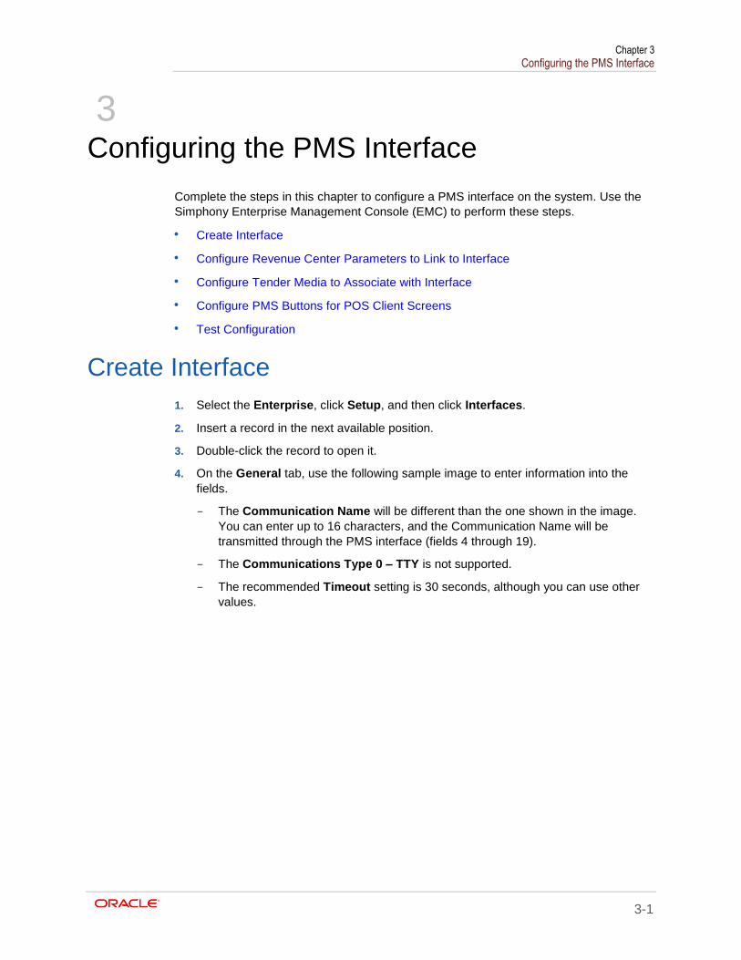
4. On the General tab, use the following sample image to enter information into the
fields.
- The Communication Name will be different than the one shown in the image.
You can enter up to 16 characters, and the Communication Name will be
transmitted through the PMS interface (fields 4 through 19).
- The Communications Type 0 – TTY is not supported.
- The recommended Timeout setting is 30 seconds, although you can use other
values.
Chapter 3 Configuring the PMS Interface
3-2
Figure 1 - Interfaces General Settings
5. Click the Options tab.
a. Select 3-Allow Inquiry without Sign-In. This option enables room inquires to
occur from the sign in page of a workstation while no employees are signed in.
b. Select 9-Determine Link Status Using Ping.
c. In the TCP Host Name field, enter the IP address of the PMS server.
d. In the TCP Port field, enter the port number to use on the PMS server.
6. Click the Properties tab, and then select the property that can use this interface.
7. Click the Service Host tab, and then select the service host that will run the
interface.
8. Click Save.
Configure Revenue Center Parameters to Link to
Interface
1. Select the Enterprise, property, or revenue center, click Setup, and then click RVC
Parameters.
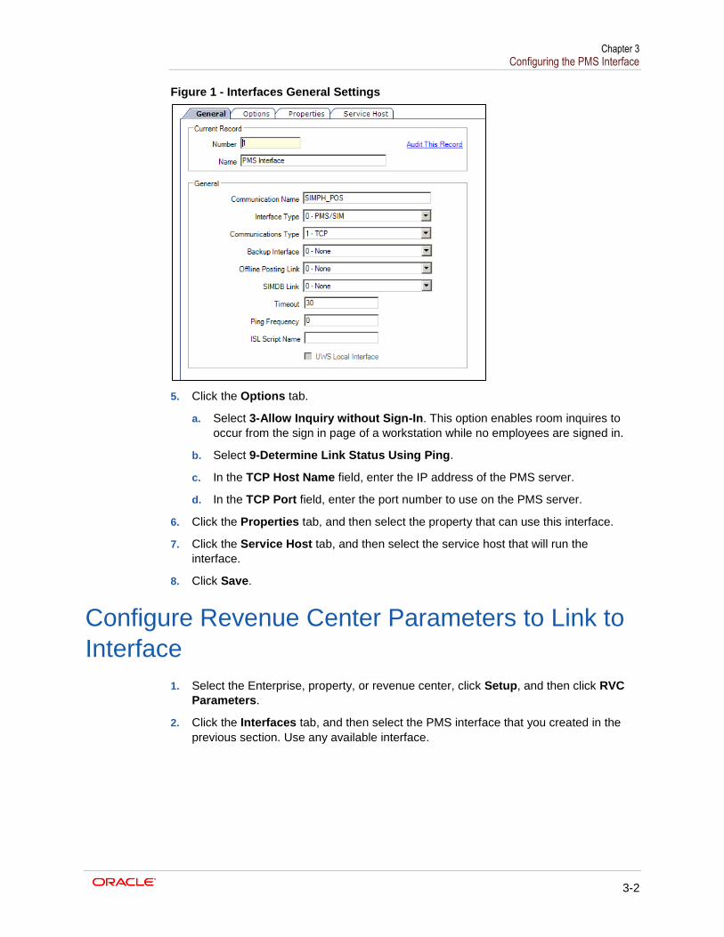
2. Click the Interfaces tab, and then select the PMS interface that you created in the
previous section. Use any available interface.
Chapter 3 Configuring the PMS Interface
3-3
Figure 3-2 – RVC Parameters Interfaces Links 1
3. Click Save.
The next sections of the configuration will use the interface link number when binding to
this interface – not the actual record number of the interface. The interface link number
has a value of 1 – 16. In the image above, interface 1 – PMS Interface is bound to
interface link #1. This link number will be used as the example for the remainder of the
document.
The following image shows how the interface might be associated with a different link
number. In this case, interface 1 – PMS Interface is configured to use link #4. This means
that any tenders or inquires that are to be associated with that interface use interface link
#4.
Figure 3-3 - RVC Parameters Interfaces Links 2
Configure Tender Media to Associate with
Interface
1. Select the Enterprise or property, click Configuration, and then click Tender/Media.
2. Insert a new tender media record, or select an existing record to modify.
3. Click the Options tab, and then click the Interface Options tab.
4. Select the Interface Link number that you used in the RVC Parameters module.
5. If you are using standard PMS interface posting, deselect option 38; use ISL Timed
procedure rather than the PMS interface.
6. Click the Ops Behavior tab, and then select option 5-Reference Enter Required.
7. Click Save.
Chapter 3 Configuring the PMS Interface
3-4
Configure PMS Buttons for POS Client Screens
1. Select the Enterprise, property, revenue center, or zone, click Configuration, and
then click Page Design.
2. Open the page on which to place the PMS buttons.
3. On the Edit tab, select the page area in which to define the buttons.
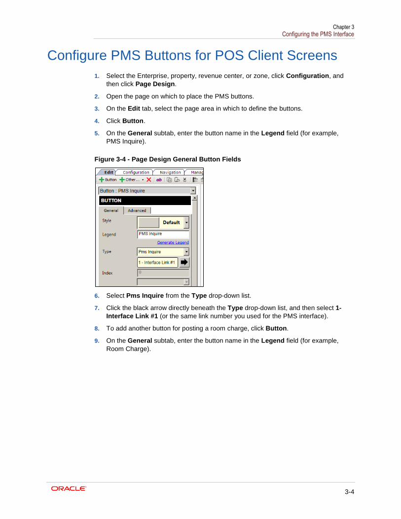
4. Click Button.
5. On the General subtab, enter the button name in the Legend field (for example,
PMS Inquire).
Figure 3-4 - Page Design General Button Fields
6. Select Pms Inquire from the Type drop-down list.
7. Click the black arrow directly beneath the Type drop-down list, and then select 1-
Interface Link #1 (or the same link number you used for the PMS interface).
8. To add another button for posting a room charge, click Button.
9. On the General subtab, enter the button name in the Legend field (for example,
Room Charge).
Chapter 3 Configuring the PMS Interface
3-5
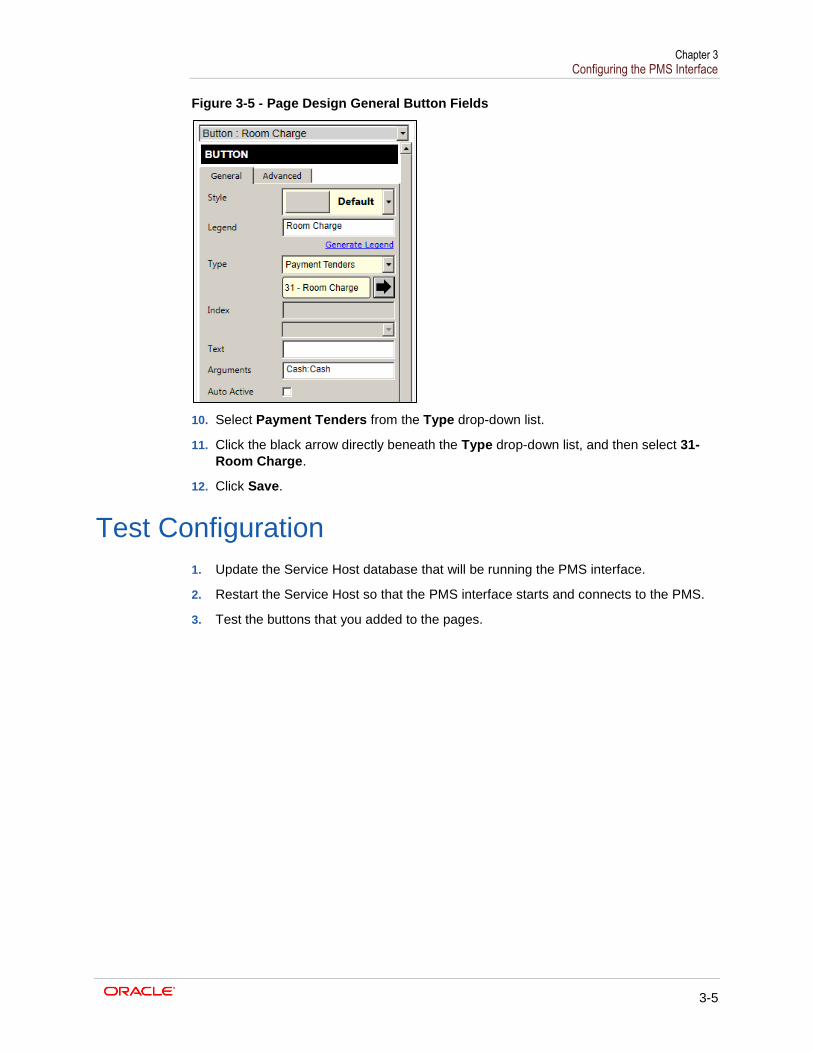
Figure 3-5 - Page Design General Button Fields
10. Select Payment Tenders from the Type drop-down list.
11. Click the black arrow directly beneath the Type drop-down list, and then select 31-
Room Charge.
12. Click Save.
Test Configuration
1. Update the Service Host database that will be running the PMS interface.
2. Restart the Service Host so that the PMS interface starts and connects to the PMS.
3. Test the buttons that you added to the pages.
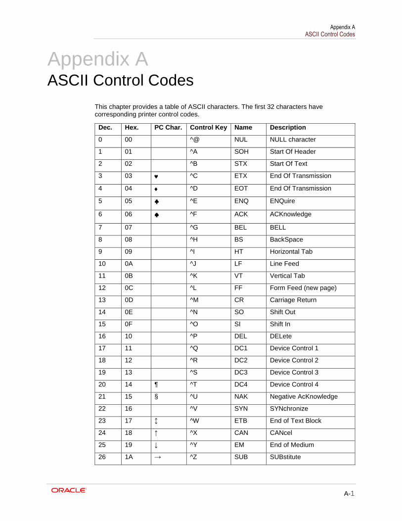
Appendix A ASCII Control Codes
A-1
Appendix A
ASCII Control Codes
This chapter provides a table of ASCII characters. The first 32 characters have corresponding printer control codes.
Dec. Hex. PC Char. Control Key Name Description
0 00 ^@ NUL NULL character
1 01 ^A SOH Start Of Header
2 02 ^B STX Start Of Text
3 03 ^C ETX End Of Transmission
4 04 ^D EOT End Of Transmission
5 05 ♣ ^E ENQ ENQuire
6 06 ♠ ^F ACK ACKnowledge
7 07 ^G BEL BELL
8 08 ^H BS BackSpace
9 09 ^I HT Horizontal Tab
10 0A ^J LF Line Feed
11 0B ^K VT Vertical Tab
12 0C ^L FF Form Feed (new page)
13 0D ^M CR Carriage Return
14 0E ^N SO Shift Out
15 0F ^O SI Shift In
16 10 ^P DEL DELete
17 11 ^Q DC1 Device Control 1
18 12 ^R DC2 Device Control 2
19 13 ^S DC3 Device Control 3
20 14 ¶ ^T DC4 Device Control 4
21 15 § ^U NAK Negative AcKnowledge
22 16 ^V SYN SYNchronize
23 17 ↕ ^W ETB End of Text Block
24 18 ↑ ^X CAN CANcel
25 19 ↓ ^Y EM End of Medium
26 1A → ^Z SUB SUBstitute
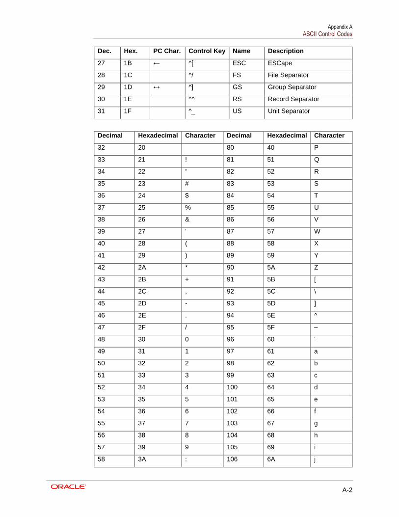
Appendix A ASCII Control Codes
A-2
Dec. Hex. PC Char. Control Key Name Description
27 1B ← ^[ ESC ESCape
28 1C ^/ FS File Separator
29 1D ↔ ^] GS Group Separator
30 1E ^^ RS Record Separator
31 1F ^_ US Unit Separator
Decimal Hexadecimal Character Decimal Hexadecimal Character
32 20 80 40 P
33 21 ! 81 51 Q
34 22 “ 82 52 R
35 23 # 83 53 S
36 24 $ 84 54 T
37 25 % 85 55 U
38 26 & 86 56 V
39 27 ‘ 87 57 W
40 28 ( 88 58 X
41 29 ) 89 59 Y
42 2A * 90 5A Z
43 2B + 91 5B [
44 2C , 92 5C \
45 2D - 93 5D ]
46 2E . 94 5E ^
47 2F / 95 5F –
48 30 0 96 60 ‘
49 31 1 97 61 a
50 32 2 98 62 b
51 33 3 99 63 c
52 34 4 100 64 d
53 35 5 101 65 e
54 36 6 102 66 f
55 37 7 103 67 g
56 38 8 104 68 h
57 39 9 105 69 i
58 3A : 106 6A j
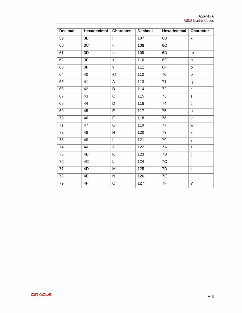
Appendix A ASCII Control Codes
A-3
Decimal Hexadecimal Character Decimal Hexadecimal Character
59 3B ; 107 6B k
60 3C < 108 6C l
61 3D = 109 6D m
62 3E > 110 6E n
63 3F ? 111 6F o
64 40 @ 112 70 p
65 41 A 113 71 q
66 42 B 114 72 r
67 43 C 115 73 s
68 44 D 116 74 t
69 45 E 117 75 u
70 46 F 118 76 v
71 47 G 119 77 w
72 48 H 120 78 x
73 49 I 121 79 y
74 4A J 122 7A z
75 4B K 123 7B {
76 4C L 124 7C |
77 4D M 125 7D }
78 4E N 126 7E ~
79 4F O 127 7F ?