oracle fusion middleware · oracle® fusion middleware administering clusters for oracle weblogic...
TRANSCRIPT

Oracle® Fusion MiddlewareAdministering Clusters for Oracle WebLogic Server
12c (12.2.1.2.0)
E77955-02
November 2016
This document describes clusters and provides information forplanning, implementing, and supporting a productionenvironment that includes WebLogic Server clusters.

Oracle Fusion Middleware Administering Clusters for Oracle WebLogic Server, 12c (12.2.1.2.0)
E77955-02
Copyright © 2007, 2016, Oracle and/or its affiliates. All rights reserved.
This software and related documentation are provided under a license agreement containing restrictions onuse and disclosure and are protected by intellectual property laws. Except as expressly permitted in yourlicense agreement or allowed by law, you may not use, copy, reproduce, translate, broadcast, modify, license,transmit, distribute, exhibit, perform, publish, or display any part, in any form, or by any means. Reverseengineering, disassembly, or decompilation of this software, unless required by law for interoperability, isprohibited.
The information contained herein is subject to change without notice and is not warranted to be error-free. Ifyou find any errors, please report them to us in writing.
If this is software or related documentation that is delivered to the U.S. Government or anyone licensing it onbehalf of the U.S. Government, then the following notice is applicable:
U.S. GOVERNMENT END USERS: Oracle programs, including any operating system, integrated software,any programs installed on the hardware, and/or documentation, delivered to U.S. Government end users are"commercial computer software" pursuant to the applicable Federal Acquisition Regulation and agency-specific supplemental regulations. As such, use, duplication, disclosure, modification, and adaptation of theprograms, including any operating system, integrated software, any programs installed on the hardware,and/or documentation, shall be subject to license terms and license restrictions applicable to the programs.No other rights are granted to the U.S. Government.
This software or hardware is developed for general use in a variety of information management applications.It is not developed or intended for use in any inherently dangerous applications, including applications thatmay create a risk of personal injury. If you use this software or hardware in dangerous applications, then youshall be responsible to take all appropriate fail-safe, backup, redundancy, and other measures to ensure itssafe use. Oracle Corporation and its affiliates disclaim any liability for any damages caused by use of thissoftware or hardware in dangerous applications.
Oracle and Java are registered trademarks of Oracle and/or its affiliates. Other names may be trademarks oftheir respective owners.
Intel and Intel Xeon are trademarks or registered trademarks of Intel Corporation. All SPARC trademarks areused under license and are trademarks or registered trademarks of SPARC International, Inc. AMD, Opteron,the AMD logo, and the AMD Opteron logo are trademarks or registered trademarks of Advanced MicroDevices. UNIX is a registered trademark of The Open Group.
This software or hardware and documentation may provide access to or information about content, products,and services from third parties. Oracle Corporation and its affiliates are not responsible for and expresslydisclaim all warranties of any kind with respect to third-party content, products, and services unlessotherwise set forth in an applicable agreement between you and Oracle. Oracle Corporation and its affiliateswill not be responsible for any loss, costs, or damages incurred due to your access to or use of third-partycontent, products, or services, except as set forth in an applicable agreement between you and Oracle.

Contents
Preface ................................................................................................................................................................ xi
Documentation Accessibility ..................................................................................................................... xi
Conventions.................................................................................................................................................. xi
1 Introduction and Roadmap
1.1 Document Scope and Audience..................................................................................................... 1-1
1.2 Guide to this Document.................................................................................................................. 1-1
1.3 Related Documentation .................................................................................................................. 1-2
1.4 New and Changed Clustering Features in This Release............................................................ 1-2
2 Understanding WebLogic Server Clustering
2.1 What Is a WebLogic Server Cluster?............................................................................................. 2-1
2.2 What Are Dynamic Clusters?......................................................................................................... 2-1
2.3 How Does a Cluster Relate to a Domain? .................................................................................... 2-2
2.4 What Are the Benefits of Clustering? ........................................................................................... 2-2
2.5 What Are the Key Capabilities of a Cluster? ............................................................................... 2-3
2.6 What Types of Objects Can Be Clustered?................................................................................... 2-4
2.6.1 Servlets and JSPs .................................................................................................................. 2-5
2.6.2 EJBs and RMI Objects .......................................................................................................... 2-5
2.6.3 JMS and Clustering .............................................................................................................. 2-6
2.7 What Types of Objects Cannot Be Clustered? ............................................................................. 2-6
3 Communications In a Cluster
3.1 Choosing WebLogic Server Cluster Messaging Protocols......................................................... 3-1
3.1.1 Using IP Multicast ................................................................................................................ 3-1
3.1.2 One-to-Many Communication Using Unicast ................................................................. 3-4
3.1.3 Considerations for Choosing Unicast or Multicast ......................................................... 3-9
3.2 Peer-to-Peer Communication Using IP Sockets ........................................................................ 3-10
3.2.1 Pure-Java Versus Native Socket Reader Implementations .......................................... 3-10
3.2.2 Configuring Reader Threads for Java Socket Implementation.................................... 3-11
3.3 Client Communication via Sockets ............................................................................................. 3-13
3.4 Cluster-Wide JNDI Naming Service ........................................................................................... 3-13
iii
3.4.1 How WebLogic Server Creates the Cluster-Wide JNDI Tree ...................................... 3-14
3.4.2 How JNDI Naming Conflicts Occur................................................................................ 3-15
3.4.3 How WebLogic Server Updates the JNDI Tree ............................................................. 3-16
3.4.4 Client Interaction with the Cluster-Wide JNDI Tree..................................................... 3-16
4 Understanding Cluster Configuration
4.1 Cluster Configuration and config.xml.......................................................................................... 4-1
4.2 Role of the Administration Server................................................................................................. 4-2
4.2.1 What Happens if the Administration Server Fails? ........................................................ 4-3
4.3 How Dynamic Configuration Works............................................................................................ 4-3
4.4 Application Deployment for Clustered Configurations ............................................................ 4-4
4.4.1 Deployment Methods .......................................................................................................... 4-4
4.4.2 Introduction to Two-Phase Deployment .......................................................................... 4-5
4.4.3 Guidelines for Deploying to a Cluster ............................................................................. 4-5
4.5 Methods of Configuring Clusters.................................................................................................. 4-7
5 Load Balancing in a Cluster
5.1 Load Balancing for Servlets and JSPs ........................................................................................... 5-1
5.1.1 Load Balancing with a Proxy Plug-in................................................................................ 5-1
5.1.2 Load Balancing HTTP Sessions with an External Load Balancer ................................. 5-2
5.2 Load Balancing for EJBs and RMI Objects ................................................................................... 5-3
5.2.1 Round-Robin Load Balancing ............................................................................................ 5-4
5.2.2 Weight-Based Load Balancing ........................................................................................... 5-4
5.2.3 Random Load Balancing ..................................................................................................... 5-5
5.2.4 Server Affinity Load Balancing Algorithms..................................................................... 5-5
5.2.5 Parameter-Based Routing for Clustered Objects ............................................................. 5-9
5.2.6 Optimization for Collocated Objects ................................................................................. 5-9
5.2.7 XA Transaction Cluster Affinity ...................................................................................... 5-11
5.3 Load Balancing for JMS ................................................................................................................ 5-12
5.3.1 Server Affinity for Distributed JMS Destinations ......................................................... 5-12
5.3.2 Initial Context Affinity and Server Affinity for Client Connections .......................... 5-12
6 Failover and Replication in a Cluster
6.1 How WebLogic Server Detects Failures ....................................................................................... 6-1
6.1.1 Failure Detection Using IP Sockets .................................................................................... 6-1
6.1.2 The WebLogic Server "Heartbeat" ..................................................................................... 6-1
6.2 Replication and Failover for Servlets and JSPs............................................................................ 6-2
6.2.1 HTTP Session State Replication ......................................................................................... 6-2
6.2.2 Accessing Clustered Servlets and JSPs Using a Proxy.................................................... 6-7
6.2.3 Accessing Clustered Servlets and JSPs with Load Balancing Hardware..................... 6-8
6.2.4 Session State Replication Across Clusters in a MAN/WAN....................................... 6-11
6.3 Replication and Failover for EJBs and RMIs.............................................................................. 6-20
6.3.1 Clustering Objects with Replica-Aware Stubs .............................................................. 6-20
iv
6.3.2 Clustering Support for Different Types of EJBs............................................................. 6-21
6.3.3 Clustering Support for RMI Objects ................................................................................ 6-24
6.3.4 Object Deployment Requirements................................................................................... 6-25
7 Whole Server Migration
7.1 Understanding Server and Service Migration............................................................................. 7-1
7.2 Migration Terminology................................................................................................................... 7-2
7.3 Leasing............................................................................................................................................... 7-3
7.3.1 Features That Use Leasing .................................................................................................. 7-3
7.3.2 Types of Leasing................................................................................................................... 7-3
7.3.3 Determining Which Type of Leasing To Use ................................................................... 7-4
7.3.4 High-availability Database Leasing................................................................................... 7-4
7.3.5 Non-database Consensus Leasing ..................................................................................... 7-6
7.4 Automatic Whole Server Migration.............................................................................................. 7-7
7.4.1 Preparing for Automatic Whole Server Migration.......................................................... 7-7
7.4.2 Configuring Automatic Whole Server Migration............................................................ 7-8
7.4.3 Using High Availability Storage for State Data ............................................................. 7-10
7.4.4 Server Migration Processes and Communications........................................................ 7-11
7.5 Whole Server Migration with Dynamic and Mixed Clusters.................................................. 7-18
7.5.1 Configuring Whole Server Migration with Dynamic Clusters.................................... 7-18
7.5.2 Configuring Whole Server Migration with Mixed Clusters ........................................ 7-19
8 Service Migration
8.1 Understanding the Service Migration Framework..................................................................... 8-1
8.1.1 Migratable Services .............................................................................................................. 8-2
8.1.2 Understanding Migratable Targets In a Cluster .............................................................. 8-3
8.1.3 Migration Processing Tools................................................................................................. 8-8
8.1.4 Automatic Service Migration Infrastructure .................................................................... 8-9
8.1.5 In-Place Restarting of Failed Migratable Services ......................................................... 8-11
8.1.6 Migrating a Service From an Unavailable Server.......................................................... 8-11
8.1.7 JMS and JTA Automatic Service Migration Interaction................................................ 8-12
8.2 Pre-Migration Requirements........................................................................................................ 8-12
8.2.1 Custom Store Availability for JMS Services ................................................................... 8-12
8.2.2 Default File Store Availability for JTA ............................................................................ 8-13
8.2.3 Server State and Manual Service Migration ................................................................... 8-13
8.3 Roadmap for Configuring Automatic Migration of JMS-related Services............................ 8-14
8.3.1 Step 1: Configure Managed Servers and Node Manager ............................................. 8-15
8.3.2 Step 2: Configure the Migration Leasing Basis .............................................................. 8-15
8.3.3 Step 3: Configure Migratable Targets.............................................................................. 8-15
8.3.4 Step 4: Configure and Target Custom Stores ................................................................. 8-17
8.3.5 Step 5: Target the JMS Services......................................................................................... 8-18
8.3.6 Step 6: Restart the Administration Server and Managed Servers With Modified
Migration Policies ..................................................................................................................... 8-18
v
8.3.7 Step 7: Manually Migrate JMS Services Back to the Original Server.......................... 8-18
8.4 Best Practices for Targeting JMS when Configuring Automatic Service Migration............ 8-18
8.5 Roadmap for Configuring Manual Migration of JMS-related Services ................................. 8-20
8.5.1 Step 1: Configure Managed Servers ................................................................................ 8-20
8.5.2 Step 2: Configure Migratable Targets.............................................................................. 8-20
8.5.3 Step 3: Configure and Target Custom Stores ................................................................. 8-22
8.5.4 Step 4: Target the JMS Services......................................................................................... 8-22
8.5.5 Step 5: Restart the Administration Server and Managed Servers With Modified
Migration Policies ..................................................................................................................... 8-22
8.5.6 Step 6: Manually Migrating JMS Services....................................................................... 8-23
8.6 Roadmap for Configuring Automatic Migration of the JTA Transaction Recovery Service
.............................................................................................................................................................. 8-23
8.6.1 Step 1: Configure Managed Servers and Node Manager ............................................. 8-23
8.6.2 Step 2: Configure the Migration Basis ............................................................................. 8-24
8.6.3 Step 3: Enable Automatic JTA Migration........................................................................ 8-24
8.6.4 Step 4: Configure the Default Persistent Store For Transaction Recovery Service
Migration.................................................................................................................................... 8-26
8.6.5 Step 5: Restart the Administration Server and Managed Servers With Modified
Migration Policies ..................................................................................................................... 8-26
8.6.6 Step 6: Automatic Failback of the Transaction Recovery Service Back to the
Original Server .......................................................................................................................... 8-26
8.7 Manual Migration of the JTA Transaction Recovery Service.................................................. 8-26
8.8 Automatic Migration of User-Defined Singleton Services ...................................................... 8-27
8.8.1 Overview of Singleton Service Migration....................................................................... 8-27
8.8.2 Implementing the Singleton Service Interface ............................................................... 8-28
8.8.3 Deploying a Singleton Service and Configuring the Migration Behavior ................. 8-29
9 Cluster Architectures
9.1 Architectural and Cluster Terminology ....................................................................................... 9-1
9.1.1 Architecture........................................................................................................................... 9-1
9.1.2 Web Application Tiers ......................................................................................................... 9-1
9.1.3 Combined Tier Architecture ............................................................................................... 9-2
9.1.4 De-Militarized Zone (DMZ)................................................................................................ 9-2
9.1.5 Load Balancer........................................................................................................................ 9-2
9.1.6 Proxy Plug-In ........................................................................................................................ 9-2
9.2 Recommended Basic Architecture ................................................................................................ 9-2
9.2.1 When Not to Use a Combined Tier Architecture ............................................................ 9-4
9.3 Recommended Multi-Tier Architecture ....................................................................................... 9-4
9.3.1 Physical Hardware and Software Layers.......................................................................... 9-5
9.3.2 Benefits of Multi-Tier Architecture.................................................................................... 9-6
9.3.3 Load Balancing Clustered Objects in a in Multi-Tier Architecture............................... 9-6
9.3.4 Configuration Considerations for Multi-Tier Architecture............................................ 9-8
9.3.5 Limitations of Multi-Tier Architectures ............................................................................ 9-8
vi
9.4 Recommended Proxy Architectures ............................................................................................. 9-9
9.4.1 Two-Tier Proxy Architecture.............................................................................................. 9-9
9.4.2 Multi-Tier Proxy Architecture .......................................................................................... 9-11
9.4.3 Proxy Architecture Benefits .............................................................................................. 9-11
9.4.4 Proxy Architecture Limitations ........................................................................................ 9-12
9.4.5 Proxy Plug-In Versus Load Balancer............................................................................... 9-12
9.5 Security Options for Cluster Architectures................................................................................ 9-12
9.5.1 Basic Firewall for Proxy Architectures............................................................................ 9-12
9.5.2 Additional Security for Shared Databases...................................................................... 9-16
10 Setting up WebLogic Clusters
10.1 Before You Start ........................................................................................................................... 10-1
10.1.1 Understand the Configuration Process......................................................................... 10-1
10.1.2 Determine Your Cluster Architecture ........................................................................... 10-1
10.1.3 Consider Your Network and Security Topologies ...................................................... 10-2
10.1.4 Choose Machines for the Cluster Installation .............................................................. 10-2
10.1.5 Identify Names and Addresses ...................................................................................... 10-3
10.2 Cluster Implementation Procedures ......................................................................................... 10-7
10.2.1 Configuration Roadmap.................................................................................................. 10-7
10.2.2 Install WebLogic Server................................................................................................... 10-8
10.2.3 Create a Clustered Domain............................................................................................. 10-8
10.2.4 Configure Node Manager ............................................................................................. 10-10
10.2.5 Configure Load Balancing Method for EJBs and RMIs ............................................ 10-10
10.2.6 Specifying a Timeout Value For RMIs ........................................................................ 10-11
10.2.7 Configure Server Affinity for Distributed JMS Destinations................................... 10-11
10.2.8 Configuring Load Balancers that Support Passive Cookie Persistence ................. 10-11
10.2.9 Configure Proxy Plug-Ins.............................................................................................. 10-12
10.2.10 Configure Replication Groups.................................................................................... 10-19
10.2.11 Configure Migratable Targets for Pinned Services ................................................. 10-20
10.2.12 Package Applications for Deployment ..................................................................... 10-20
10.2.13 Deploy Applications .................................................................................................... 10-20
10.2.14 Deploying, Activating, and Migrating Migratable Services .................................. 10-21
10.2.15 Configure In-Memory HTTP Replication ................................................................. 10-24
10.2.16 Additional Configuration Topics............................................................................... 10-24
11 Dynamic Clusters
11.1 What Are Dynamic Clusters?..................................................................................................... 11-1
11.2 Why Do You Use Dynamic Clusters? ....................................................................................... 11-2
11.3 How Do Dynamic Clusters Work?............................................................................................ 11-2
11.3.1 Creating and Configuring Dynamic Clusters .............................................................. 11-3
11.3.2 Using Server Templates................................................................................................... 11-3
11.3.3 Calculating Server-Specific Attributes .......................................................................... 11-3
11.3.4 Starting and Stopping Servers in Dynamic Clusters................................................... 11-6
vii

11.3.5 Expanding or Reducing Dynamic Clusters .................................................................. 11-7
11.3.6 Using Whole Server Migration with Dynamic Clusters............................................. 11-8
11.3.7 Deploying Applications to Dynamic Clusters ............................................................. 11-8
11.3.8 Using WebLogic Web Server Plug-Ins with Dynamic Clusters ................................ 11-8
11.4 Limitations and Considerations When Using Dynamic Clusters......................................... 11-8
11.5 Dynamic Clusters Example ........................................................................................................ 11-9
12 Configuring and Managing Coherence Clusters
12.1 Overview of Coherence Clusters............................................................................................... 12-1
12.2 Setting Up a Coherence Cluster................................................................................................. 12-2
12.2.1 Define a Coherence Cluster Resource ........................................................................... 12-3
12.2.2 Create Standalone Managed Coherence Servers ......................................................... 12-3
12.3 Creating Coherence Deployment Tiers .................................................................................... 12-4
12.3.1 Configuring and Managing a Coherence Data Tier .................................................... 12-5
12.3.2 Configuring and Managing a Coherence Application Tier ....................................... 12-6
12.3.3 Configuring and Managing a Coherence Proxy Tier .................................................. 12-7
12.4 Configuring a Coherence Cluster............................................................................................ 12-11
12.4.1 Adding and Removing Coherence Cluster Members............................................... 12-11
12.4.2 Setting Advanced Cluster Configuration Options .................................................... 12-12
12.4.3 Configure Cluster Communication ............................................................................. 12-12
12.4.4 Overriding a Cache Configuration File....................................................................... 12-14
12.4.5 Configuring Coherence Logging.................................................................................. 12-16
12.4.6 Configuring Cache Persistence..................................................................................... 12-16
12.4.7 Configuring Cache Federation ..................................................................................... 12-17
12.5 Configuring Managed Coherence Servers ............................................................................. 12-17
12.5.1 Configure Coherence Cluster Member Storage Settings .......................................... 12-18
12.5.2 Configure Coherence Cluster Member Unicast Settings.......................................... 12-18
12.5.3 Removing a Coherence Management Proxy .............................................................. 12-19
12.5.4 Configure Coherence Cluster Member Identity Settings ......................................... 12-19
12.5.5 Configure Coherence Cluster Member Logging Levels ........................................... 12-20
12.6 Using a Single-Server Cluster .................................................................................................. 12-20
12.7 Using WLST with Coherence................................................................................................... 12-21
12.8 Persisting Coherence Caches with WLST .............................................................................. 12-23
13 Clustering Best Practices
13.1 General Design Considerations ................................................................................................. 13-1
13.1.1 Strive for Simplicity ......................................................................................................... 13-1
13.1.2 Minimize Remote Calls ................................................................................................... 13-1
13.2 Web Application Design Considerations................................................................................. 13-2
13.2.1 Configure In-Memory Replication ................................................................................ 13-2
13.2.2 Design for Idempotence ................................................................................................. 13-2
13.2.3 Programming Considerations ........................................................................................ 13-2
13.3 EJB Design Considerations......................................................................................................... 13-2
viii
13.3.1 Design Idempotent Methods .......................................................................................... 13-2
13.3.2 Follow Usage and Configuration Guidelines............................................................... 13-3
13.4 State Management in a Cluster .................................................................................................. 13-5
13.5 Application Deployment Considerations ................................................................................ 13-9
13.6 Architecture Considerations ...................................................................................................... 13-9
13.7 Avoiding Problems...................................................................................................................... 13-9
13.7.1 Naming Considerations................................................................................................... 13-9
13.7.2 Administration Server Considerations ......................................................................... 13-9
13.7.3 Firewall Considerations................................................................................................. 13-10
13.7.4 Evaluate Cluster Capacity Prior to Production Use.................................................. 13-11
14 Troubleshooting Common Problems
14.1 Before You Start the Cluster ....................................................................................................... 14-1
14.1.1 Check the Server Version Numbers .............................................................................. 14-1
14.1.2 Check the Multicast Address.......................................................................................... 14-1
14.1.3 Check the CLASSPATH Value ....................................................................................... 14-2
14.2 After You Start the Cluster ......................................................................................................... 14-2
14.2.1 Check Your Commands .................................................................................................. 14-2
14.2.2 Generate a Log File........................................................................................................... 14-2
14.2.3 Check Garbage Collection............................................................................................... 14-4
14.2.4 Run utils.MulticastTest.................................................................................................... 14-4
15 Troubleshooting Multicast Configuration
15.1 Verifying Multicast Address and Port Configuration............................................................ 15-1
15.1.1 Possible Errors .................................................................................................................. 15-2
15.1.2 Checking the Multicast Address and Port.................................................................... 15-2
15.2 Identifying Network Configuration Problems........................................................................ 15-2
15.2.1 Physical Connections ....................................................................................................... 15-2
15.2.2 Address Conflicts ............................................................................................................. 15-2
15.2.3 nsswitch.conf Settings on UNIX Systems ..................................................................... 15-2
15.3 Using the MulticastTest Utility.................................................................................................. 15-2
15.4 Tuning Multicast Features.......................................................................................................... 15-3
15.4.1 Multicast Timeouts........................................................................................................... 15-3
15.4.2 Cluster Heartbeats............................................................................................................ 15-3
15.4.3 Multicast Storms............................................................................................................... 15-4
15.4.4 Multicast and Multihomed Machines ........................................................................... 15-4
15.4.5 Multicast in Different Subnets........................................................................................ 15-4
15.5 Debugging Multicast ................................................................................................................... 15-4
15.5.1 Debugging Utilities .......................................................................................................... 15-5
15.5.2 Debugging Flags............................................................................................................... 15-5
15.6 Miscellaneous Issues ................................................................................................................... 15-5
15.6.1 Multicast on AIX............................................................................................................... 15-6
15.6.2 File Descriptor Problems ................................................................................................. 15-6
ix
15.7 Other Resources for Troubleshooting Multicast Configuration ........................................... 15-6
A The WebLogic Cluster API
A.1 How to Use the API........................................................................................................................ A-1
A.2 Custom Call Routing and Collocation Optimization ................................................................ A-2
B Configuring BIG-IP Hardware with Clusters
C Configuring F5 Load Balancers for MAN/WAN Failover
C.1 Requirements................................................................................................................................... C-1
C.2 Configure Local Load Balancers ................................................................................................... C-1
C.2.1 Virtual Server IPs and Pools .............................................................................................. C-2
C.2.2 Create a Failover Trigger Virtual Server and Pool ......................................................... C-2
C.2.3 Create a Multi-layered Virtual Server and IP Pool......................................................... C-3
C.3 Configure the 3-DNS Global Hardware Load Balancer............................................................ C-3
C.3.1 Configure DNS Zones......................................................................................................... C-4
C.3.2 Configure BIG-IP Addresses Managed by 3-DNS.......................................................... C-4
C.3.3 Configure Data Centers ...................................................................................................... C-4
C.3.4 Configure Wide IPs ............................................................................................................. C-4
C.4 Configuring WebLogic Server Components............................................................................... C-5
D Configuring Radware Load Balancers for MAN/WAN Failover
D.1 Requirements................................................................................................................................... D-1
D.2 Step 1: Configure an Authoritative Delegation Zone................................................................ D-2
D.3 Step 2: Configure Farm Virtual IPs and Servers ........................................................................ D-2
D.3.1 Create a Farm IP .................................................................................................................. D-2
D.3.2 Configure the Dispatch Method for the Server Farm .................................................... D-2
D.3.3 Creating Farm Servers ........................................................................................................ D-3
D.4 Step 3: Configure Port Multiplexing............................................................................................ D-3
D.5 Step 4: Configure HTTP Redirects ............................................................................................... D-3
D.6 Step 5: Configure Session ID Persistency .................................................................................... D-4
D.7 Step 6: Configure LRP.................................................................................................................... D-4
D.8 Step 7: Configure WebLogic Server Components...................................................................... D-5
Index
x
Preface
This preface describes the document accessibility features and conventions used in thisguide—Administering Clusters for Oracle WebLogic Server.
Documentation AccessibilityFor information about Oracle's commitment to accessibility, visit the OracleAccessibility Program website at http://www.oracle.com/pls/topic/lookup?ctx=acc&id=docacc.
Access to Oracle Support
Oracle customers that have purchased support have access to electronic supportthrough My Oracle Support. For information, visit http://www.oracle.com/pls/topic/lookup?ctx=acc&id=info or visit http://www.oracle.com/pls/topic/lookup?ctx=acc&id=trs if you are hearing impaired.
ConventionsThe following text conventions are used in this document:
Convention Meaning
boldface Boldface type indicates graphical user interface elements associatedwith an action, or terms defined in text or the glossary.
italic Italic type indicates book titles, emphasis, or placeholder variables forwhich you supply particular values.
monospace Monospace type indicates commands within a paragraph, URLs, codein examples, text that appears on the screen, or text that you enter.
xi

1Introduction and Roadmap
This chapter describes the contents and organization of this guide—AdministeringClusters for Oracle WebLogic Server.
This chapter includes the following sections:
• Document Scope and Audience
• Guide to this Document
• Related Documentation
• New and Changed Clustering Features in This Release
1.1 Document Scope and AudienceThis document is written for application developers and administrators who aredeveloping or deploying Web-based applications on one or more clusters. It alsocontains information that is useful for business analysts and system architects who areevaluating WebLogic Server or considering the use of WebLogic Server clusters for aparticular application.
The topics in this document are primarily relevant to planning, implementing, andsupporting a production environment that includes WebLogic Server clusters. Keyguidelines for software engineers who design or develop applications that will run ona WebLogic Server cluster are also addressed.
It is assumed that the reader is familiar with Java EE, HTTP, HTML coding, and Javaprogramming (servlets, JSP, or EJB development).
1.2 Guide to this Document• This chapter, Introduction and Roadmap, describes the organization of this guide.
• Understanding WebLogic Server Clustering provides a brief introduction toWebLogic Server clusters.
• Communications In a Cluster describes how WebLogic Server instancescommunicate to one another in a cluster and how they utilize a cluster-wide JNDItree.
• Understanding Cluster Configuration explains how the information that definesthe configuration of a cluster is stored and maintained, and identifies the methodsyou can use to accomplish cluster configuration tasks.
• Load Balancing in a Cluster describes the load balancing support that a WebLogicServer cluster provides for different types of objects, and provides planning andconfiguration considerations for architects and administrators.
Introduction and Roadmap 1-1
• Failover and Replication in a Cluster describes how WebLogic Server detectsfailures in a cluster, and summarizes how failover is accomplished for differenttypes of objects.
• Whole Server Migration describes the different migration mechanisms supportedby WebLogic Server.
• Service Migration describes the service migration mechanisms supported byWebLogic Server:
• Cluster Architectures describes alternative architectures for a WebLogic Servercluster.
• Setting up WebLogic Clusters contains guidelines and instructions for configuringa WebLogic Server cluster.
• Dynamic Clusters introduces and describes dynamic clusters.
• Configuring and Managing Coherence Clusters describes how to configure andmanage Coherence clusters.
• Clustering Best Practices provides recommendations for design and deploymentpractices that maximize the scalability, reliability, and performance of applicationshosted by a WebLogic Server cluster.
• Troubleshooting Common Problems provides guidelines on how to prevent andtroubleshoot common cluster problems.
• The WebLogic Cluster API describes the WebLogic Cluster API.
• Configuring BIG-IP Hardware with Clusters describes options for configuring anF5 BIG-IP controller to operate with a WebLogic Server cluster.
• Configuring F5 Load Balancers for MAN/WAN Failover explains how to configureF5 hardware load balancers.
• Configuring Radware Load Balancers for MAN/WAN Failover describes how toconfigure Radware hardware load balancers.
1.3 Related Documentation• Understanding Enterprise JavaBeans in Developing Enterprise JavaBeans, Version 2.1,
for Oracle WebLogic Server
• Creating and Configuring Web Applications in Developing Web Applications,Servlets, and JSPs for Oracle WebLogic Server.
1.4 New and Changed Clustering Features in This ReleaseThis release of WebLogic Server adds WLST commands to improve usability fordynamic cluster lifecycle operations. By using the WLST scaleUp and scaleDowncommands, you can easily start and stop dynamic servers in a dynamic cluster andexpand or shrink the size of a dynamic cluster. For more information, see Starting andStopping Servers in Dynamic Clusters and Expanding or Reducing Dynamic Clusters.
For a comprehensive listing of the new WebLogic Server features introduced in thisrelease, see What's New in Oracle WebLogic Server 12.2.1.2.0.
Related Documentation
1-2 Administering Clusters for Oracle WebLogic Server
2Understanding WebLogic Server Clustering
This chapter provides a brief introduction to WebLogic Server clusters.
This chapter includes the following sections:
• What Is a WebLogic Server Cluster?
• What Are Dynamic Clusters?
• How Does a Cluster Relate to a Domain?
• What Are the Benefits of Clustering?
• What Are the Key Capabilities of a Cluster?
• What Types of Objects Can Be Clustered?
• What Types of Objects Cannot Be Clustered?
2.1 What Is a WebLogic Server Cluster?A WebLogic Server cluster consists of multiple WebLogic Server server instancesrunning simultaneously and working together to provide increased scalability andreliability. A cluster appears to clients to be a single WebLogic Server instance. Theserver instances that constitute a cluster can run on the same machine, or be located ondifferent machines. You can increase a cluster's capacity by adding additional serverinstances to the cluster on an existing machine, or you can add machines to the clusterto host the incremental server instances. Each server instance in a cluster must run thesame version of WebLogic Server.
2.2 What Are Dynamic Clusters?Dynamic clusters consist of server instances that can be dynamically scaled up to meetthe resource needs of your application. A dynamic cluster uses a single servertemplate to define configuration for a specified number of generated (dynamic) serverinstances.
When you create a dynamic cluster, the dynamic servers are preconfigured andautomatically generated for you, enabling you to easily scale up the number of serverinstances in your dynamic cluster when you need additional server capacity. You cansimply start the dynamic servers without having to first manually configure and addthem to the cluster.
For more information about dynamic clusters, see Dynamic Clusters and Createdynamic clusters in the Oracle WebLogic Server Administration Console Online Help.
Understanding WebLogic Server Clustering 2-1
2.3 How Does a Cluster Relate to a Domain?A cluster is part of a particular WebLogic Server domain.
A domain is an interrelated set of WebLogic Server resources that are managed as aunit. A domain includes one or more WebLogic Server instances, which can beclustered, non-clustered, or a combination of clustered and non-clustered instances. Adomain can include multiple clusters. A domain also contains the applicationcomponents deployed in the domain, and the resources and services required by thoseapplication components and the server instances in the domain. Examples of theresources and services used by applications and server instances include machinedefinitions, optional network channels, connectors, and startup classes.
You can use a variety of criteria for organizing WebLogic Server instances intodomains. For instance, you might choose to allocate resources to multiple domainsbased on logical divisions of the hosted application, geographical considerations, orthe number or complexity of the resources under management. For additionalinformation about domains, see Understanding Domain Configuration for OracleWebLogic Server.
In each domain, one WebLogic Server instance acts as the Administration Server—theserver instance which configures, manages, and monitors all other server instancesand resources in the domain. Each Administration Server manages one domain only.If a domain contains multiple clusters, each cluster in the domain has the sameAdministration Server.
All server instances in a cluster must reside in the same domain; you cannot "split" acluster over multiple domains. Similarly, you cannot share a configured resource orsubsystem between domains.
Clustered WebLogic Server instances behave similarly to non-clustered instances,except that they provide failover and load balancing. The process and tools used toconfigure clustered WebLogic Server instances are the same as those used to configurenon-clustered instances. However, to achieve the load balancing and failover benefitsthat clustering enables, you must adhere to certain guidelines for cluster configuration.
To understand how the failover and load balancing mechanisms used in WebLogicServer relate to particular configuration options see Load Balancing in a Cluster, and Failover and Replication in a Cluster.
Detailed configuration recommendations are included throughout the instructions in Setting up WebLogic Clusters.
2.4 What Are the Benefits of Clustering?A WebLogic Server cluster provides these benefits:
• Scalability
The capacity of an application deployed on a WebLogic Server cluster can beincreased dynamically to meet demand. You can add server instances to a clusterwithout interruption of service—the application continues to run without impact toclients and end users.
• High-Availability
In a WebLogic Server cluster, application processing can continue when a serverinstance fails. You "cluster" application components by deploying them on multipleserver instances in the cluster—so, if a server instance on which a component is
How Does a Cluster Relate to a Domain?
2-2 Administering Clusters for Oracle WebLogic Server
running fails, another server instance on which that component is deployed cancontinue application processing.
The choice to cluster WebLogic Server instances is transparent to applicationdevelopers and clients. However, understanding the technical infrastructure thatenables clustering will help programmers and administrators maximize the scalabilityand availability of their applications.
2.5 What Are the Key Capabilities of a Cluster?This section defines, in non-technical terms, the key clustering capabilities that enablescalability and high availability.
• Application Failover
Simply put, failover means that when an application component (typically referredto as an "object" in the following sections) doing a particular "job"—some set ofprocessing tasks—becomes unavailable for any reason, a copy of the failed objectfinishes the job.
For the new object to be able to take over for the failed object:
– There must be a copy of the failed object available to take over the job.
– There must be information, available to other objects and the program thatmanages failover, defining the location and operational status of all objects—sothat it can be determined that the first object failed before finishing its job.
– There must be information, available to other objects and the program thatmanages failover, about the progress of jobs in process—so that an object takingover an interrupted job knows how much of the job was completed before thefirst object failed, for example, what data has been changed, and what steps inthe process were completed.
WebLogic Server uses standards-based communication techniques and facilities—including IP sockets and the Java Naming and Directory Interface (JNDI)—to shareand maintain information about the availability of objects in a cluster. Thesetechniques allow WebLogic Server to determine that an object stopped beforefinishing its job, and where there is a copy of the object to complete the job that wasinterrupted.
Note:
For backward compatibility with previous versions, WebLogic Server allowsyou to use multicast for communications between clusters.
Information about what has been done on a job is called state. WebLogic Servermaintains information about state using techniques called session replication andreplica-aware stubs. When a particular object unexpectedly stops doing its job,replication techniques enable a copy of the object pick up where the failed objectstopped, and finish the job.
• WebLogic Server supports automatic and manual migration of a clustered serverinstance from one machine to another. A Managed Server that can be migrated isreferred to as a migratable server. This feature is designed for environments withrequirements for high availability. The server migration capability is useful for:
What Are the Key Capabilities of a Cluster?
Understanding WebLogic Server Clustering 2-3
– Ensuring uninterrupted availability of singleton services—services that must runon only a single server instance at any given time, such as JMS and the JTAtransaction recovery system, when the hosting server instance fails. A ManagedServer configured for automatic migration will be automatically migrated toanother machine in the event of failure.
– Easing the process of relocating a Managed Server, and all the services it hosts,as part of a planned system administration process. To initiate the migration ofa Managed Server, you can use any of the administration tools listed in Summary of System Administration Tools and APIs in Understanding OracleWebLogic Server.
The server migration process relocates a Managed Server in its entirety—includingIP addresses and hosted applications—to one of a predefined set of available hostmachines.
• Load Balancing
Load balancing is the even distribution of jobs and associated communicationsacross the computing and networking resources in your environment. For loadbalancing to occur:
– There must be multiple copies of an object that can do a particular job.
– Information about the location and operational status of all objects must beavailable.
WebLogic Server allows objects to be clustered—deployed on multiple serverinstances—so that there are alternative objects to do the same job. WebLogicServer shares and maintains the availability and location of deployed objectsusing unicast, IP sockets, and JNDI.
Note:
For backward compatibility with previous versions, WebLogic Server alsoallows you to use multicast for communications between clusters.
A detailed discussion of how communications and replication techniques areemployed by WebLogic Server is provided in Communications In a Cluster.
2.6 What Types of Objects Can Be Clustered?A clustered application or application component is one that is available on multipleWebLogic Server instances in a cluster. If an object is clustered, failover and loadbalancing for that object is available. Deploy objects homogeneously—to every serverinstance in your cluster—to simplify cluster administration, maintenance, andtroubleshooting.
Web applications can consist of different types of objects, including Enterprise JavaBeans (EJBs), servlets, and Java Server Pages (JSPs). Each object type has a unique setof behaviors related to control, invocation, and how it functions within an application.For this reason, the methods that WebLogic Server uses to support clustering—andhence to provide load balancing and failover—can vary for different types of objects.The following types of objects can be clustered in a WebLogic Server deployment:
• Servlets
What Types of Objects Can Be Clustered?
2-4 Administering Clusters for Oracle WebLogic Server
• JSPs
• EJBs
• Remote Method Invocation (RMI) objects
• Java Messaging Service (JMS) destinations
Different object types can have certain behaviors in common. When this is the case, theclustering support and implementation considerations for those similar object typesmay be same. In the sections that follow, explanations and instructions for thefollowing types of objects are generally combined:
• Servlets and JSPs
• EJBs and RMI objects
The sections that follow briefly describe the clustering, failover, and load balancingsupport that WebLogic Server provides for different types of objects.
2.6.1 Servlets and JSPsWebLogic Server provides clustering support for servlets and JSPs by replicating theHTTP session state of clients that access clustered servlets and JSPs. WebLogic Servercan maintain HTTP session states in memory, a file system, or a database.
To enable automatic failover of servlets and JSPs, session state must persist inmemory. For information about how failover works for servlets and JSPs, and forrelated requirements and programming considerations, see HTTP Session StateReplication.
You can balance the servlet and JSP load across a cluster using a WebLogic Serverproxy plug-in or external load balancing hardware. WebLogic Server proxy plug-insperform round-robin load balancing. External load balancers typically support avariety of session load balancing mechanisms. For more information, see LoadBalancing for Servlets and JSPs.
2.6.2 EJBs and RMI ObjectsLoad balancing and failover for EJBs and RMI objects is handled using replica-awarestubs, which can locate instances of the object throughout the cluster. Replica-awarestubs are created for EJBs and RMI objects as a result of the object compilation process.EJBs and RMI objects are deployed homogeneously—to all the server instances in thecluster.
Failover for EJBs and RMI objects is accomplished using the object's replica-awarestub. When a client makes a call through a replica-aware stub to a service that fails, thestub detects the failure and retries the call on another replica. To understand failoversupport for different types of objects, see Replication and Failover for EJBs and RMIs.
WebLogic Server clusters support multiple algorithms for load balancing clusteredEJBs and RMI objects: round-robin, weight-based, random, round-robin-affinity,weight-based-affinity, and random-affinity. By default, a WebLogic Server cluster willuse the round-robin method. You can configure a cluster to use one of the othermethods using the WebLogic Server Administration Console. The method you select ismaintained within the replica-aware stub obtained for clustered objects. For details,see Load Balancing for EJBs and RMI Objects.
What Types of Objects Can Be Clustered?
Understanding WebLogic Server Clustering 2-5
2.6.3 JMS and ClusteringThe WebLogic Java Messaging Service (JMS) architecture implements clustering ofmultiple JMS servers by supporting cluster-wide, transparent access to destinationsfrom any WebLogic Server server instance in the cluster. Although WebLogic Serversupports distributing JMS destinations and connection factories throughout a cluster,the same JMS topic or queue is still managed separately by each WebLogic Serverinstance in the cluster.
Load balancing is supported for JMS. To enable load balancing, you must configuretargets for JMS servers. For more information about load balancing and JMScomponents, see Load Balancing for JMS, For instructions on setting up clustered JMS,see Configure Migratable Targets for Pinned Services, and Deploying_ Activating_and Migrating Migratable Services.
2.7 What Types of Objects Cannot Be Clustered?The following APIs and internal services cannot be clustered in WebLogic Server:
• File services including file shares
• Time services
You can still use these services on individual WebLogic Server instances in a cluster.However, the services do not make use of load balancing or failover features.
What Types of Objects Cannot Be Clustered?
2-6 Administering Clusters for Oracle WebLogic Server
3Communications In a Cluster
This chapter describes how WebLogic Server clusters communicate using IP socketsand IP unicast or multicast.
WebLogic Server instances in a cluster communicate with one another using two basicnetwork technologies:
• IP unicast or multicast, which server instances use to broadcast availability ofservices and heartbeats that indicate continued availability. See Considerations forChoosing Unicast or Multicast for information on selecting unicast or multicast.
• IP sockets, which are the conduits for peer-to-peer communication betweenclustered server instances.
This chapter includes the following sections:
• Choosing WebLogic Server Cluster Messaging Protocols
• Peer-to-Peer Communication Using IP Sockets
• Client Communication via Sockets
• Cluster-Wide JNDI Naming Service
3.1 Choosing WebLogic Server Cluster Messaging ProtocolsWebLogic Server supports two cluster messaging protocols:
• Multicast: This protocol relies on UDP multicast and has been supported inWebLogic Server clusters since WebLogic Server 4.0.
• Unicast: This protocol relies on point-to-point TCP/IP sockets and was added inWebLogic Server 10.0.
This section includes the following topics:
• Using IP Multicast
• One-to-Many Communication Using Unicast
• Considerations for Choosing Unicast or Multicast
3.1.1 Using IP MulticastMulticast is a simple broadcast technology that enables multiple applications to"subscribe" to a given IP address and port number and listen for messages.
Communications In a Cluster 3-1
Note:
A multicast address is an IP address in the range from 224.0.0.0 to239.255.255.255. The default multicast value used by WebLogic Server is239.192.0.0. You should not use any multicast address within the range x.0.0.1.Multicast ports have the normal UDP port ranges (0 to 65535), however certainUDP ports are reserved for specific purposes and should generally beavoided.
Multicast broadcasts messages to applications, but it does not guarantee that messagesare actually received. If an application's local multicast buffer is full, new multicastmessages cannot be written to the buffer and the application is not notified whenmessages are "dropped." Because of this limitation, WebLogic Server instances allowfor the possibility that they may occasionally miss messages that were broadcast overmulticast.
The WebLogic Server multicast implementation uses standard UDP multicast tobroadcast the cluster messages to a group that is explicitly listening on the multicastaddress and port over which the message is sent. Since UDP is not a reliable protocol,WebLogic Server builds its own reliable messaging protocol into the messages it sendsto detect and retransmit lost messages.
Most operating systems and switches support UDP multicast by default betweenmachines in the same subnet. However, most routers do not support the propagationof UDP multicast messages between subnets by default. In environments that dosupport UDP multicast message propagation, UDP multicast has a time-to-live (TTL)mechanism built into the protocol. Each time the message reaches a router, the TTL isdecremented by 1 before it routes the message. When the TTL reaches zero, themessage will no longer be propagated between networks, making it an effectivecontrol for the range of a UDP multicast message. By default, WebLogic Server sets theTTL for its multicast cluster messages to 1, which restricts the message to the currentsubnet.
When using multicast, the cluster heartbeat mechanism will remove a server instancefrom the cluster if it misses three heartbeat messages in a row to account for the factthat UDP is not considered a reliable protocol. Since the default heartbeat frequency isone heartbeat every 10 seconds, this means it can take up to 30 seconds to detect that aserver instance has left the cluster. Socket death detection or failed connectionattempts can also accelerate this detection.
In summary, WebLogic Server multicast cluster messaging protocol:
• Uses a very efficient and scalable peer-to-peer model where a server instance sendseach message directly to the network once and the network makes sure that eachcluster member receives the message directly from the network.
• Works out of the box in most environments where the cluster members are in asingle subnet.
• Requires additional configuration in the router and WebLogic Server (for examplemulticast TTL) if the cluster members span more than one subnet.
• Uses three consecutive missed heartbeats to remove a server instance from anotherserver's cluster membership list.
Choosing WebLogic Server Cluster Messaging Protocols
3-2 Administering Clusters for Oracle WebLogic Server
To test an environment for its ability to support the WebLogic Server multicastmessaging protocol, WebLogic Server provides a Java command-line utility known as MulticastTest.
WebLogic Server uses multicast for all one-to-many communications among serverinstances in a cluster. This communication includes:
• Cluster-wide JNDI updates—Each WebLogic Server instance in a cluster usesmulticast to announce the availability of clustered objects that are deployed orremoved locally. Each server instance in the cluster monitors these announcementsand updates its local JNDI tree to reflect current deployments of clustered objects.For more details, see Cluster-Wide JNDI Naming Service.
• Cluster heartbeats—Each WebLogic Server instance in a cluster uses multicast tobroadcast regular "heartbeat" messages that advertise its availability. Bymonitoring heartbeat messages, server instances in a cluster determine when aserver instance has failed. (Clustered server instances also monitor IP sockets as amore immediate method of determining when a server instance has failed.)
• Clusters with many nodes—Multicast communication is the option of choice forclusters with many nodes.
3.1.1.1 Multicast and Cluster Configuration
Because multicast communications control critical functions related to detectingfailures and maintaining the cluster-wide JNDI tree (described in Cluster-Wide JNDINaming Service) it is important that neither the cluster configuration nor the networktopology interfere with multicast communications. The sections that follow provideguidelines for avoiding problems with multicast communication in a cluster.
3.1.1.1.1 If Your Cluster Spans Multiple Subnets In a WAN
In many deployments, clustered server instances reside within a single subnet,ensuring multicast messages are reliably transmitted. However, you may want todistribute a WebLogic Server cluster across multiple subnets in a Wide Area Network(WAN) to increase redundancy, or to distribute clustered server instances over alarger geographical area.
If you choose to distribute a cluster over a WAN (or across multiple subnets), plan andconfigure your network topology to ensure that multicast messages are reliablytransmitted to all server instances in the cluster. Specifically, your network must meetthe following requirements:
• Full support of IP multicast packet propagation. In other words, all routers andother tunneling technologies must be configured to propagate multicast messagesto clustered server instances.
• Network latency low enough to ensure that most multicast messages reach theirfinal destination in approximately 10 milliseconds.
• Multicast Time-To-Live (TTL) value for the cluster high enough to ensure thatrouters do not discard multicast packets before they reach their final destination.For instructions on setting the Multicast TTL parameter, see Configure MulticastTime-To-Live (TTL).
Choosing WebLogic Server Cluster Messaging Protocols
Communications In a Cluster 3-3
Note:
Distributing a WebLogic Server cluster over a WAN may require networkfacilities in addition to the multicast requirements described above. Forexample, you may want to configure load balancing hardware to ensure thatclient requests are directed to server instances in the most efficient manner (toavoid unnecessary network hops).
3.1.1.1.2 Firewalls Can Break Multicast Communication
Although it may be possible to tunnel multicast traffic through a firewall, this practiceis not recommended for WebLogic Server clusters. Treat each WebLogic Server clusteras a logical unit that provides one or more distinct services to clients of a Webapplication. Do not split this logical unit between different security zones.Furthermore, any technologies that potentially delay or interrupt IP traffic can disrupta WebLogic Server cluster by generating false failures due to missed heartbeats.
3.1.1.1.3 Do Not Share the Cluster Multicast Address with Other Applications
Although multiple WebLogic Server clusters can share a single IP multicast addressand port, other applications should not broadcast or subscribe to the multicast addressand port used by your cluster or clusters. That is, if the machine or machines that hostyour cluster also host other applications that use multicast communications, makesure that those applications use a different multicast address and port than the clusterdoes.
Sharing the cluster multicast address with other applications forces clustered serverinstances to process unnecessary messages, introducing overhead. Sharing a multicastaddress may also overload the IP multicast buffer and delay transmission of WebLogicServer heartbeat messages. Such delays can result in a WebLogic Server instance beingmarked as failed, simply because its heartbeat messages were not received in a timelymanner.
For these reasons, assign a dedicated multicast address for use by WebLogic Serverclusters, and ensure that the address can support the broadcast traffic of all clustersthat use the address.
3.1.1.1.4 If Multicast Storms Occur
If server instances in a cluster do not process incoming messages on a timely basis,increased network traffic, including negative acknowledgement (NAK) messages andheartbeat re-transmissions, can result. The repeated transmission of multicast packetson a network is referred to as a multicast storm, and can stress the network andattached stations, potentially causing end-stations to hang or fail. Increasing the size ofthe multicast buffers can improve the rate at which announcements are transmittedand received, and prevent multicast storms. See Configure Multicast Buffer Size.
3.1.2 One-to-Many Communication Using UnicastThe WebLogic Server unicast protocol uses standard TCP/IP sockets to send messagesbetween cluster members. Since all networks and network devices support TCP/IPsockets, unicast simplifies out-of-the-box-cluster configuration. It typically requires noadditional configuration, regardless of the network topology between clustermembers. Additionally, unicast reduces potential network errors that can occur frommulticast address conflicts. WebLogic Server uses unicast as its default clusterprotocol.
Choosing WebLogic Server Cluster Messaging Protocols
3-4 Administering Clusters for Oracle WebLogic Server
3.1.2.1 WebLogic Server Unicast Groups
Since TCP/IP sockets are a point-to-point mechanism, all cluster members receivemessages directly. To limit the number of sockets required as a cluster grows,WebLogic Server's unicast implementation uses a group leader mechanism. With thismechanism:
• WebLogic Server divides the server instances in a cluster into a fixed number ofgroups.
• Each group includes one server instance that also functions as the group leader. Ifthe group leader fails, the group elects another group leader.
• To send and receive cluster messages, each server instance in a group makes aTCP/IP socket connection only to the group leader. The group leader connects toall its group members and all other group leaders in the cluster.
• When a group leader receives a cluster message from a server instance in its group,it retransmits the message to all other members in the group and also to everyother group leader in the cluster. The other group leaders then retransmit themessage to all their group members. This enables each server instance to receiveevery message in a cluster without requiring that server to establish a connection toevery other server instance in the cluster.
When using unicast, server instances send heartbeats to advertise their availability,similar to multicast. By monitoring heartbeat messages, server instances determinewhen another server instance fails. However, with unicast, the cluster heartbeatmechanism removes a server instance from the cluster if it misses a single heartbeatmessage, since TCP/IP is a reliable protocol.
Unicast checks for missed heartbeats every 15 seconds, instead of every 10 seconds asin multicast. This extra five seconds allows sufficient time for the message to travelfrom the remote group's member to the remote group's leader, then to the localgroup's leader, and finally to the local group's member. Since the default heartbeatfrequency is one heartbeat every 10 seconds, this means it should take no more than 15seconds to detect if a server instance has left the cluster. Socket death detection orfailed connection attempts can also accelerate this detection.
3.1.2.2 Assigning Server Instances to Groups
Note:
The algorithm used to assign server instances to groups has been changedfrom the algorithm used in WebLogic Server 12.1.2 and prior versions. Thenew algorithm is described in the following section. It has been optimized toprovide more flexible scaling of running clusters, and to better support usecases where Managed Servers are added to WebLogic Server clusters whilethe clusters are running.
The WebLogic Server unicast implementation internally organizes a cluster's serverinstances into 10 groups. WebLogic Server assigns server instances to groups and sortsserver instances within each group according to a server naming pattern. Since agroup contains a dynamic number of server instances, asymmetric or empty groupsmight exist, depending on the number and names of your clustered server instances.
Choosing WebLogic Server Cluster Messaging Protocols
Communications In a Cluster 3-5
To assign server instances to groups, WebLogic Server separates each server name intotwo parts: a prefix and an integer. For example, a server instance named server1separates into the prefix <server> and the integer <1>.
You can use any name for server instances. For configured servers, if the server namedoes not end with an integer, WebLogic Server calculates and assigns an initial valueto the server instance. It then uses this value to determine the appropriate group towhich it automatically assigns the server instance. For example, server instancesserverA and serverB do not have integers in their names. WebLogic Server uses theentire names for the prefixes and calculates values to use for the integers, such as 728for serverA and 729 for serverB.
Dynamic servers always follow this pattern, as a dynamic cluster uses its servertemplate settings to automatically name dynamic servers using a prefix and asequential integer number.
After associating an integer with each server name, WebLogic Server uses analgorithm to assign server instances to groups based on that integer. Within eachgroup, server instances are first sorted alphabetically by prefix and then sorted byinteger.
The first server instance in each group acts as the group leader. Under this allocationmodel, all server instances in the cluster, whether existing running servers or newlyadded servers, share a consistent view on group membership and group leader roles.
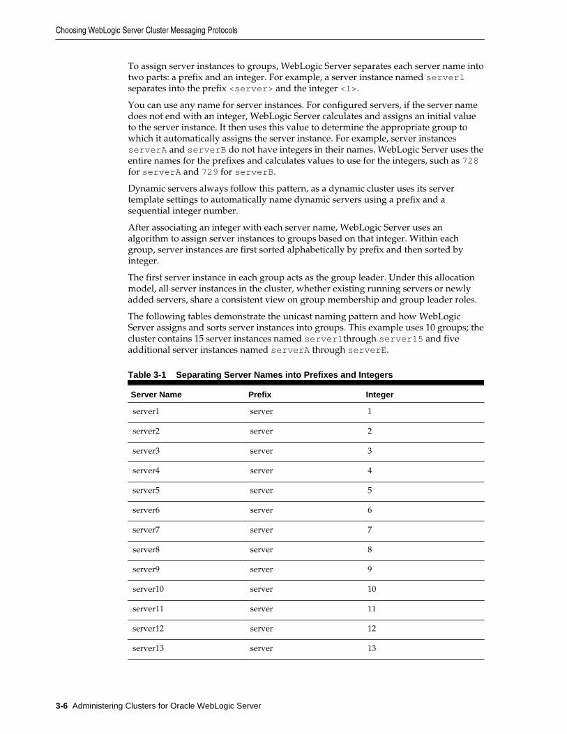
The following tables demonstrate the unicast naming pattern and how WebLogicServer assigns and sorts server instances into groups. This example uses 10 groups; thecluster contains 15 server instances named server1through server15 and fiveadditional server instances named serverA through serverE.
Table 3-1 Separating Server Names into Prefixes and Integers
Server Name Prefix Integer
server1 server 1
server2 server 2
server3 server 3
server4 server 4
server5 server 5
server6 server 6
server7 server 7
server8 server 8
server9 server 9
server10 server 10
server11 server 11
server12 server 12
server13 server 13
Choosing WebLogic Server Cluster Messaging Protocols
3-6 Administering Clusters for Oracle WebLogic Server
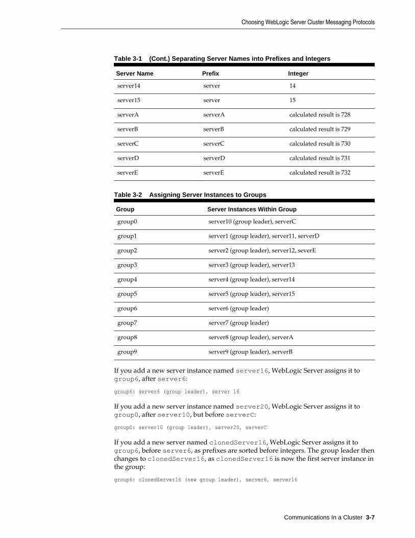
Table 3-1 (Cont.) Separating Server Names into Prefixes and Integers
Server Name Prefix Integer
server14 server 14
server15 server 15
serverA serverA calculated result is 728
serverB serverB calculated result is 729
serverC serverC calculated result is 730
serverD serverD calculated result is 731
serverE serverE calculated result is 732
Table 3-2 Assigning Server Instances to Groups
Group Server Instances Within Group
group0 server10 (group leader), serverC
group1 server1 (group leader), server11, serverD
group2 server2 (group leader), server12, severE
group3 server3 (group leader), server13
group4 server4 (group leader), server14
group5 server5 (group leader), server15
group6 server6 (group leader)
group7 server7 (group leader)
group8 server8 (group leader), serverA
group9 server9 (group leader), serverB
If you add a new server instance named server16, WebLogic Server assigns it togroup6, after server6:
group6: server6 (group leader), server 16
If you add a new server instance named server20, WebLogic Server assigns it togroup0, after server10, but before serverC:
group0: server10 (group leader), server20, serverC
If you add a new server named clonedServer16, WebLogic Server assigns it togroup6, before server6, as prefixes are sorted before integers. The group leader thenchanges to clonedServer16, as clonedServer16 is now the first server instance inthe group:
group6: clonedServer16 (new group leader), server6, server16
Choosing WebLogic Server Cluster Messaging Protocols
Communications In a Cluster 3-7
3.1.2.3 Configuring Unicast
You configure unicast using ClusterMBean.setClusterMessagingMode MBeanattribute. The default value of this parameter is unicast. Changes made to thisMBean are not dynamic. You must restart your cluster for changes to take effect.
To define a specific unicast channel, you first define a custom network channel forunicast communications with either the cluster-broadcast or the cluster-broadcast-secure protocol. After defining this custom network channel, you canassociate this channel with the cluster by specifying the channel name in the ClusterMBean.ClusterBroadcastChannel MBean attribute When unicast isenabled, servers attempt to use the value defined in this MBean attribute forcommunications between clusters. If the unicast channel is not explicitly defined, thedefault network channel is used.
Note:
The ClusterMBean.ClusterBroadcastChannel attribute is onlysupported for use only with unicast.
When you configure a WebLogic Server cluster to use unicast communications, makesure to set the listen port and the listen address for all the servers in the cluster. This isnecessary so that TCP connections can be successfully established. Specify these portsfor both static and dynamic servers, and note that you can use the IP address or theDNS name to set the listen addresses. Alternatively, you can configure a customUnicast broadcast channel. See Configure Custom Network Channels in OracleWebLogic Server Administration Console Online Help.
3.1.2.4 Considerations When Using Unicast
The following considerations apply when using unicast to handle clustercommunications in WebLogic Server 12.1.3:
• All members of a cluster must use the same message type. Using both multicastand unicast messaging is not allowed.
• Individual cluster members cannot override the cluster messaging type.
• Each server instance must have a unique combination of listen port and listenaddress.
• The entire cluster must be shut down and restarted to change message modes.
• JMS topics configured for multicasting can access WebLogic clusters configured forunicast because a JMS topic publishes messages on its own multicast address that isindependent of the cluster address. However, the following considerations apply:
– The router hardware configurations that allow unicast clusters may not allowJMS multicast subscribers to work.
– JMS multicast subscribers need to be in a network hardware configuration thatallows multicast accessibility.
For more details, see Using Multicasting with WebLogic JMS in Developing JMSApplications for Oracle WebLogic Server.
Choosing WebLogic Server Cluster Messaging Protocols
3-8 Administering Clusters for Oracle WebLogic Server
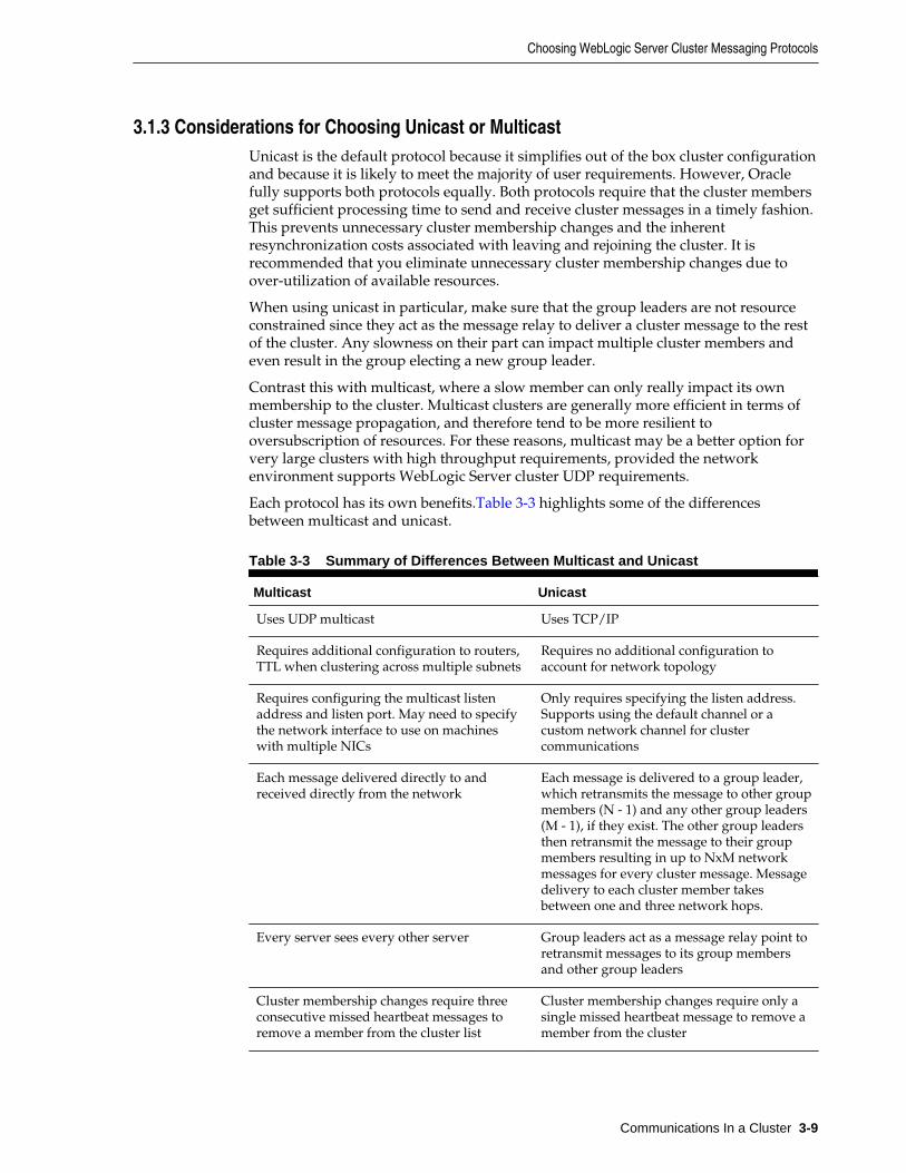
3.1.3 Considerations for Choosing Unicast or MulticastUnicast is the default protocol because it simplifies out of the box cluster configurationand because it is likely to meet the majority of user requirements. However, Oraclefully supports both protocols equally. Both protocols require that the cluster membersget sufficient processing time to send and receive cluster messages in a timely fashion.This prevents unnecessary cluster membership changes and the inherentresynchronization costs associated with leaving and rejoining the cluster. It isrecommended that you eliminate unnecessary cluster membership changes due toover-utilization of available resources.
When using unicast in particular, make sure that the group leaders are not resourceconstrained since they act as the message relay to deliver a cluster message to the restof the cluster. Any slowness on their part can impact multiple cluster members andeven result in the group electing a new group leader.
Contrast this with multicast, where a slow member can only really impact its ownmembership to the cluster. Multicast clusters are generally more efficient in terms ofcluster message propagation, and therefore tend to be more resilient tooversubscription of resources. For these reasons, multicast may be a better option forvery large clusters with high throughput requirements, provided the networkenvironment supports WebLogic Server cluster UDP requirements.
Each protocol has its own benefits.Table 3-3 highlights some of the differencesbetween multicast and unicast.
Table 3-3 Summary of Differences Between Multicast and Unicast
Multicast Unicast
Uses UDP multicast Uses TCP/IP
Requires additional configuration to routers,TTL when clustering across multiple subnets
Requires no additional configuration toaccount for network topology
Requires configuring the multicast listenaddress and listen port. May need to specifythe network interface to use on machineswith multiple NICs
Only requires specifying the listen address.Supports using the default channel or acustom network channel for clustercommunications
Each message delivered directly to andreceived directly from the network
Each message is delivered to a group leader,which retransmits the message to other groupmembers (N - 1) and any other group leaders(M - 1), if they exist. The other group leadersthen retransmit the message to their groupmembers resulting in up to NxM networkmessages for every cluster message. Messagedelivery to each cluster member takesbetween one and three network hops.
Every server sees every other server Group leaders act as a message relay point toretransmit messages to its group membersand other group leaders
Cluster membership changes require threeconsecutive missed heartbeat messages toremove a member from the cluster list
Cluster membership changes require only asingle missed heartbeat message to remove amember from the cluster
Choosing WebLogic Server Cluster Messaging Protocols
Communications In a Cluster 3-9
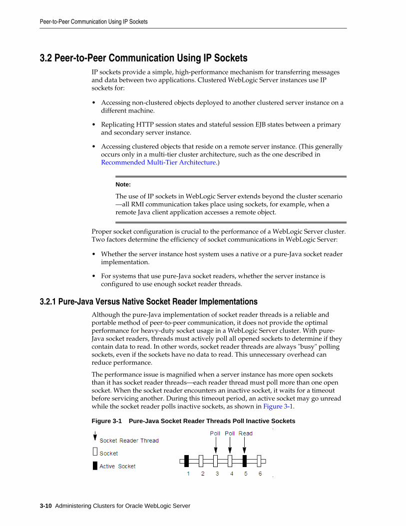
3.2 Peer-to-Peer Communication Using IP SocketsIP sockets provide a simple, high-performance mechanism for transferring messagesand data between two applications. Clustered WebLogic Server instances use IPsockets for:
• Accessing non-clustered objects deployed to another clustered server instance on adifferent machine.
• Replicating HTTP session states and stateful session EJB states between a primaryand secondary server instance.
• Accessing clustered objects that reside on a remote server instance. (This generallyoccurs only in a multi-tier cluster architecture, such as the one described in Recommended Multi-Tier Architecture.)
Note:
The use of IP sockets in WebLogic Server extends beyond the cluster scenario—all RMI communication takes place using sockets, for example, when aremote Java client application accesses a remote object.
Proper socket configuration is crucial to the performance of a WebLogic Server cluster.Two factors determine the efficiency of socket communications in WebLogic Server:
• Whether the server instance host system uses a native or a pure-Java socket readerimplementation.
• For systems that use pure-Java socket readers, whether the server instance isconfigured to use enough socket reader threads.
3.2.1 Pure-Java Versus Native Socket Reader ImplementationsAlthough the pure-Java implementation of socket reader threads is a reliable andportable method of peer-to-peer communication, it does not provide the optimalperformance for heavy-duty socket usage in a WebLogic Server cluster. With pure-Java socket readers, threads must actively poll all opened sockets to determine if theycontain data to read. In other words, socket reader threads are always "busy" pollingsockets, even if the sockets have no data to read. This unnecessary overhead canreduce performance.
The performance issue is magnified when a server instance has more open socketsthan it has socket reader threads—each reader thread must poll more than one opensocket. When the socket reader encounters an inactive socket, it waits for a timeoutbefore servicing another. During this timeout period, an active socket may go unreadwhile the socket reader polls inactive sockets, as shown in Figure 3-1.
Figure 3-1 Pure-Java Socket Reader Threads Poll Inactive Sockets
Peer-to-Peer Communication Using IP Sockets
3-10 Administering Clusters for Oracle WebLogic Server
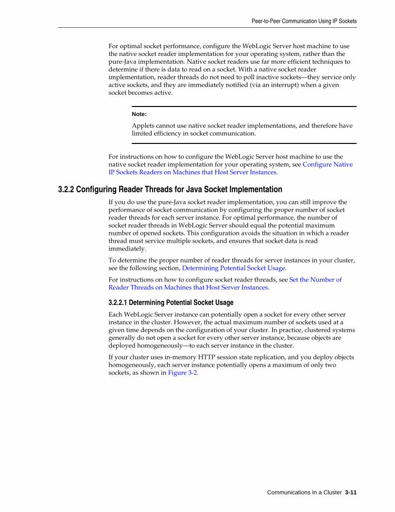
For optimal socket performance, configure the WebLogic Server host machine to usethe native socket reader implementation for your operating system, rather than thepure-Java implementation. Native socket readers use far more efficient techniques todetermine if there is data to read on a socket. With a native socket readerimplementation, reader threads do not need to poll inactive sockets—they service onlyactive sockets, and they are immediately notified (via an interrupt) when a givensocket becomes active.
Note:
Applets cannot use native socket reader implementations, and therefore havelimited efficiency in socket communication.
For instructions on how to configure the WebLogic Server host machine to use thenative socket reader implementation for your operating system, see Configure NativeIP Sockets Readers on Machines that Host Server Instances.
3.2.2 Configuring Reader Threads for Java Socket ImplementationIf you do use the pure-Java socket reader implementation, you can still improve theperformance of socket communication by configuring the proper number of socketreader threads for each server instance. For optimal performance, the number ofsocket reader threads in WebLogic Server should equal the potential maximumnumber of opened sockets. This configuration avoids the situation in which a readerthread must service multiple sockets, and ensures that socket data is readimmediately.
To determine the proper number of reader threads for server instances in your cluster,see the following section, Determining Potential Socket Usage.
For instructions on how to configure socket reader threads, see Set the Number ofReader Threads on Machines that Host Server Instances.
3.2.2.1 Determining Potential Socket Usage
Each WebLogic Server instance can potentially open a socket for every other serverinstance in the cluster. However, the actual maximum number of sockets used at agiven time depends on the configuration of your cluster. In practice, clustered systemsgenerally do not open a socket for every other server instance, because objects aredeployed homogeneously—to each server instance in the cluster.
If your cluster uses in-memory HTTP session state replication, and you deploy objectshomogeneously, each server instance potentially opens a maximum of only twosockets, as shown in Figure 3-2.
Peer-to-Peer Communication Using IP Sockets
Communications In a Cluster 3-11
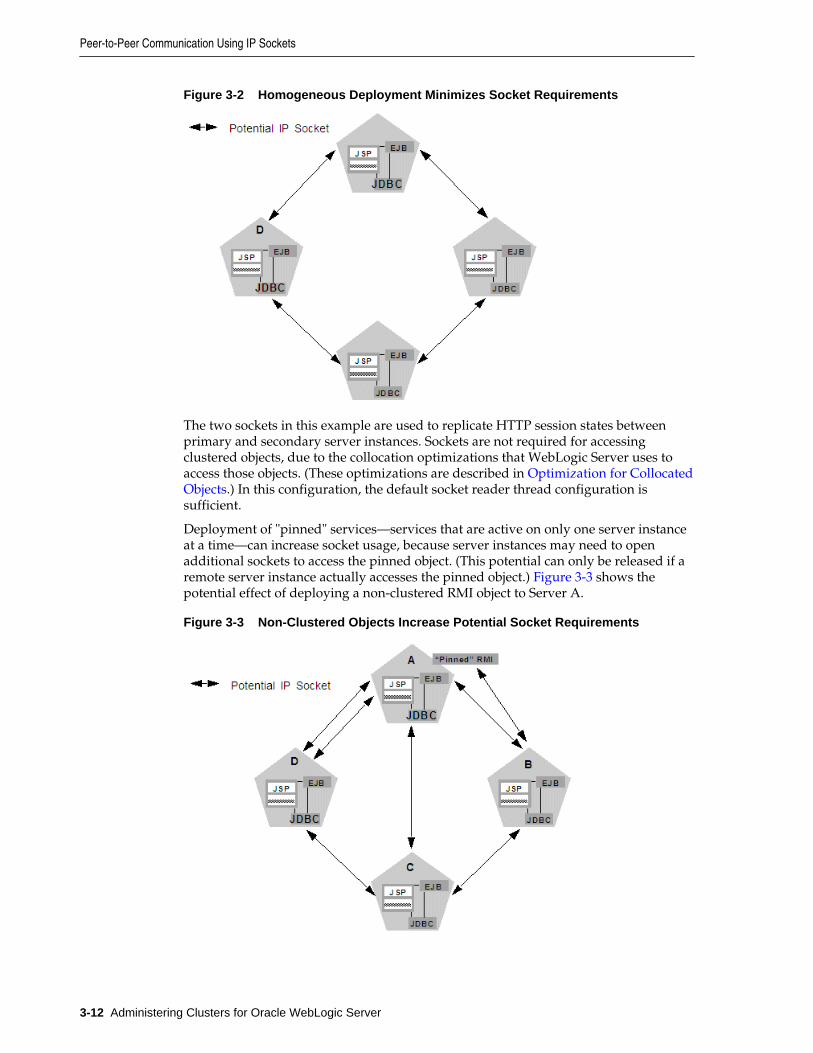
Figure 3-2 Homogeneous Deployment Minimizes Socket Requirements
The two sockets in this example are used to replicate HTTP session states betweenprimary and secondary server instances. Sockets are not required for accessingclustered objects, due to the collocation optimizations that WebLogic Server uses toaccess those objects. (These optimizations are described in Optimization for CollocatedObjects.) In this configuration, the default socket reader thread configuration issufficient.
Deployment of "pinned" services—services that are active on only one server instanceat a time—can increase socket usage, because server instances may need to openadditional sockets to access the pinned object. (This potential can only be released if aremote server instance actually accesses the pinned object.) Figure 3-3 shows thepotential effect of deploying a non-clustered RMI object to Server A.
Figure 3-3 Non-Clustered Objects Increase Potential Socket Requirements
Peer-to-Peer Communication Using IP Sockets
3-12 Administering Clusters for Oracle WebLogic Server
In this example, each server instance can potentially open a maximum of three socketsat a given time, to accommodate HTTP session state replication and to access thepinned RMI object on Server A.
Note:
Additional sockets may also be required for servlet clusters in a multi-tiercluster architecture, as described in Configuration Notes for Multi-TierArchitecture.
3.3 Client Communication via SocketsClients of a cluster use the Java implementation of socket reader threads.
WebLogic Server allows you to configure server affinity load balancing algorithmsthat reduce the number of IP sockets opened by a Java client application. A clientaccessing multiple objects on a server instance will use a single socket. If an objectfails, the client will failover to a server instance to which it already has an open socket,if possible. In older version of WebLogic Server, under some circumstances, a clientmight open a socket to each server instance in a cluster.
For optimal performance, configure enough socket reader threads in the Java VirtualMachine (JVM) that runs the client. For instructions, see Set the Number of ReaderThreads on Client Machines.
.
3.4 Cluster-Wide JNDI Naming ServiceClients of a non-clustered WebLogic Server server instance access objects and servicesby using a JNDI-compliant naming service. The JNDI naming service contains a list ofthe public services that the server instance offers, organized in a tree structure. AWebLogic Server instance offers a new service by binding into the JNDI tree a namethat represents the service. Clients obtain the service by connecting to the serverinstance and looking up the bound name of the service.
Server instances in a cluster utilize a cluster-wide JNDI tree. A cluster-wide JNDI treeis similar to a single server instance JNDI tree, insofar as the tree contains a list ofavailable services. In addition to storing the names of local services, however, thecluster-wide JNDI tree stores the services offered by clustered objects (EJBs and RMIclasses) from other server instances in the cluster.
Each WebLogic Server instance in a cluster creates and maintains a local copy of thelogical cluster-wide JNDI tree. The follow sections describe how the cluster-wide JNDItree is maintained, and how to avoid naming conflicts that can occur in a clusteredenvironment.
Note:
Do not use the cluster-wide JNDI tree as a persistence or caching mechanismfor application data. Although WebLogic Server replicates a clustered serverinstance's JNDI entries to other server instances in the cluster, those entries areremoved from the cluster if the original instance fails. Also, storing largeobjects within the JNDI tree can overload multicast or unicast traffic andinterfere with the normal operation of a cluster.
Client Communication via Sockets
Communications In a Cluster 3-13
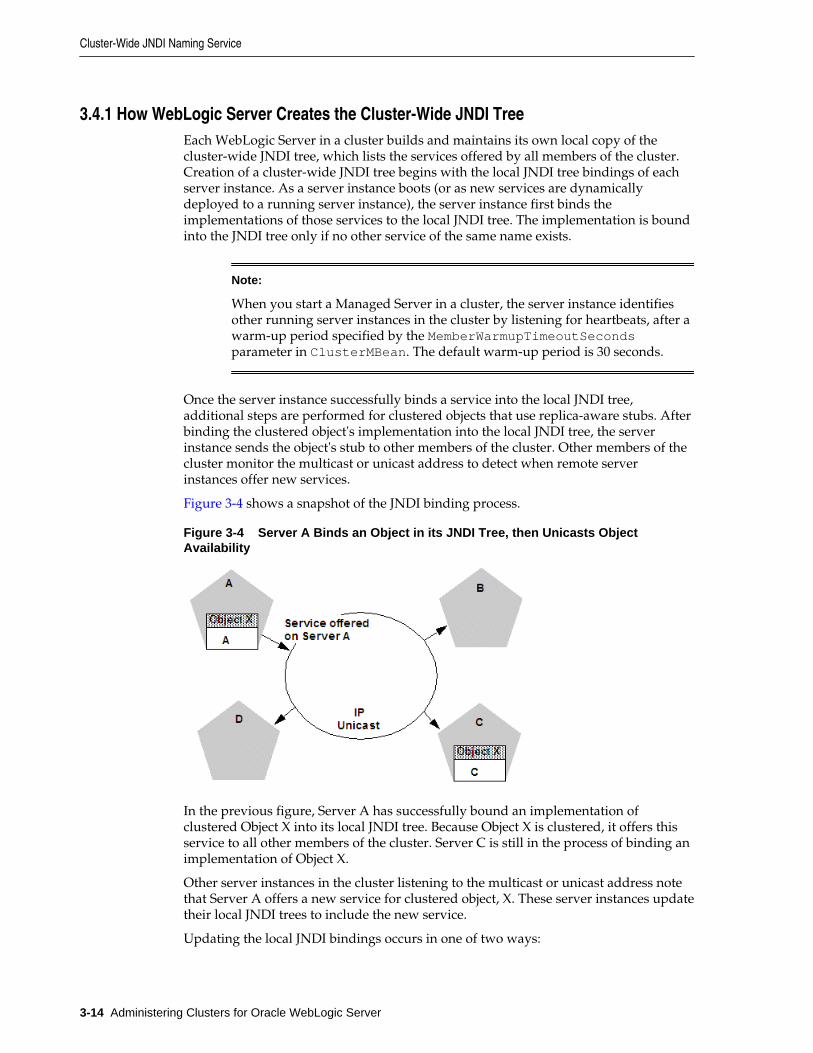
3.4.1 How WebLogic Server Creates the Cluster-Wide JNDI TreeEach WebLogic Server in a cluster builds and maintains its own local copy of thecluster-wide JNDI tree, which lists the services offered by all members of the cluster.Creation of a cluster-wide JNDI tree begins with the local JNDI tree bindings of eachserver instance. As a server instance boots (or as new services are dynamicallydeployed to a running server instance), the server instance first binds theimplementations of those services to the local JNDI tree. The implementation is boundinto the JNDI tree only if no other service of the same name exists.
Note:
When you start a Managed Server in a cluster, the server instance identifiesother running server instances in the cluster by listening for heartbeats, after awarm-up period specified by the MemberWarmupTimeoutSecondsparameter in ClusterMBean. The default warm-up period is 30 seconds.
Once the server instance successfully binds a service into the local JNDI tree,additional steps are performed for clustered objects that use replica-aware stubs. Afterbinding the clustered object's implementation into the local JNDI tree, the serverinstance sends the object's stub to other members of the cluster. Other members of thecluster monitor the multicast or unicast address to detect when remote serverinstances offer new services.
Figure 3-4 shows a snapshot of the JNDI binding process.
Figure 3-4 Server A Binds an Object in its JNDI Tree, then Unicasts ObjectAvailability
In the previous figure, Server A has successfully bound an implementation ofclustered Object X into its local JNDI tree. Because Object X is clustered, it offers thisservice to all other members of the cluster. Server C is still in the process of binding animplementation of Object X.
Other server instances in the cluster listening to the multicast or unicast address notethat Server A offers a new service for clustered object, X. These server instances updatetheir local JNDI trees to include the new service.
Updating the local JNDI bindings occurs in one of two ways:
Cluster-Wide JNDI Naming Service
3-14 Administering Clusters for Oracle WebLogic Server
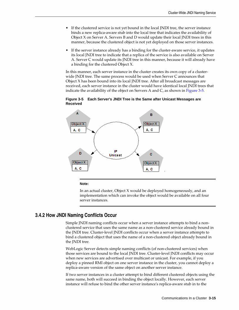
• If the clustered service is not yet bound in the local JNDI tree, the server instancebinds a new replica-aware stub into the local tree that indicates the availability ofObject X on Server A. Servers B and D would update their local JNDI trees in thismanner, because the clustered object is not yet deployed on those server instances.
• If the server instance already has a binding for the cluster-aware service, it updatesits local JNDI tree to indicate that a replica of the service is also available on ServerA. Server C would update its JNDI tree in this manner, because it will already havea binding for the clustered Object X.
In this manner, each server instance in the cluster creates its own copy of a cluster-wide JNDI tree. The same process would be used when Server C announces thatObject X has been bound into its local JNDI tree. After all broadcast messages arereceived, each server instance in the cluster would have identical local JNDI trees thatindicate the availability of the object on Servers A and C, as shown in Figure 3-5.
Figure 3-5 Each Server's JNDI Tree is the Same after Unicast Messages areReceived
Note:
In an actual cluster, Object X would be deployed homogeneously, and animplementation which can invoke the object would be available on all fourserver instances.
3.4.2 How JNDI Naming Conflicts OccurSimple JNDI naming conflicts occur when a server instance attempts to bind a non-clustered service that uses the same name as a non-clustered service already bound inthe JNDI tree. Cluster-level JNDI conflicts occur when a server instance attempts tobind a clustered object that uses the name of a non-clustered object already bound inthe JNDI tree.
WebLogic Server detects simple naming conflicts (of non-clustered services) whenthose services are bound to the local JNDI tree. Cluster-level JNDI conflicts may occurwhen new services are advertised over multicast or unicast. For example, if youdeploy a pinned RMI object on one server instance in the cluster, you cannot deploy areplica-aware version of the same object on another server instance.
If two server instances in a cluster attempt to bind different clustered objects using thesame name, both will succeed in binding the object locally. However, each serverinstance will refuse to bind the other server instance's replica-aware stub in to the
Cluster-Wide JNDI Naming Service
Communications In a Cluster 3-15
JNDI tree, due to the JNDI naming conflict. A conflict of this type would remain untilone of the two server instances was shut down, or until one of the server instancesundeployed the clustered object. This same conflict could also occur if both serverinstances attempt to deploy a pinned object with the same name.
3.4.2.1 Deploy Homogeneously to Avoid Cluster-Level JNDI Conflicts
To avoid cluster-level JNDI conflicts, you must homogeneously deploy all replica-aware objects to all WebLogic Server instances in a cluster. Having unbalanceddeployments across WebLogic Server instances increases the chance of JNDI namingconflicts during startup or redeployment. It can also lead to unbalanced processingloads in the cluster.
If you must pin specific RMI objects or EJBs to individual server instances, do notreplicate the object's bindings across the cluster.
3.4.3 How WebLogic Server Updates the JNDI TreeWhen a clustered object is removed (undeployed from a server instance), updates tothe JNDI tree are handled similarly to the updates performed when new services areadded. The server instance on which the service was undeployed broadcasts amessage indicating that it no longer provides the service. Again, other server instancesin the cluster that observe the multicast or unicast message update their local copies ofthe JNDI tree to indicate that the service is no longer available on the server instancethat undeployed the object.
Once the client has obtained a replica-aware stub, the server instances in the clustermay continue adding and removing host servers for the clustered objects. As theinformation in the JNDI tree changes, the client's stub may also be updated.Subsequent RMI requests contain update information as necessary to ensure that theclient stub remains up-to-date.
3.4.4 Client Interaction with the Cluster-Wide JNDI TreeClients that connect to a WebLogic Server cluster and look up a clustered object obtaina replica-aware stub for the object. This stub contains the list of available serverinstances that host implementations of the object. The stub also contains the loadbalancing logic for distributing the load among its host servers.
For more information about replica-aware stubs for EJBs and RMI classes, see Replication and Failover for EJBs and RMIs.
For a more detailed discussion of how WebLogic JNDI is implemented in a clusteredenvironment and how to make your own objects available to JNDI clients, see UsingWebLogic JNDI in a Clustered Environment in Developing JNDI Applications for OracleWebLogic Server.
Cluster-Wide JNDI Naming Service
3-16 Administering Clusters for Oracle WebLogic Server
4Understanding Cluster Configuration
This chapter explains how the information that defines the configuration of a cluster isstored and maintained, and the methods you can use to accomplish configurationtasks.
This chapter includes the following sections:
• Cluster Configuration and config.xml
• Role of the Administration Server
• How Dynamic Configuration Works
• Application Deployment for Clustered Configurations
• Methods of Configuring Clusters
Note:
Much of the information in this section also pertains to the process ofconfiguring a WebLogic domain in which the server instances are notclustered.
4.1 Cluster Configuration and config.xmlThe config.xml file is an XML document that describes the configuration of aWebLogic Server domain. The config.xml file consists of a series of XML elements.The <domain> element is the top-level element, and all elements in the domaindescend from the <domain> element. The <domain> element includes child elements,such as the <server>, <cluster>, and <application> and so on. These childelements may have children of their own. For example, the <server> elementincludes the child elements <WebServer>, <SSL> and <Log>. The <application>element includes the child elements <EJBComponent> and <WebAppComponent>.
Each element has one or more configurable attributes. An attribute defined inconfig.dtd has a corresponding attribute in the configuration API. For example, theServer element has a ListenPort attribute, and likewise, theweblogic.management.configuration.ServerMBean has a ListenPortattribute. Configurable attributes are readable and writable, that is, ServerMBean hasa getListenPort and a setListenPort method.
To learn more about the config.xml file, see Domain Configuration Files inUnderstanding Domain Configuration for Oracle WebLogic Server.
Understanding Cluster Configuration 4-1
4.2 Role of the Administration ServerThe Administration Server is the WebLogic Server instance that configures andmanages the WebLogic Server instances in its domain.
A domain can include multiple WebLogic Server clusters and non-clustered WebLogicServer instances. Strictly speaking, a domain could consist of only one WebLogicServer instance—however, in that case that sole server instance would be anAdministration Server, because each domain must have exactly one AdministrationServer.
There are a variety of ways to invoke the services of the Administration Server toaccomplish configuration tasks, as described in Methods of Configuring Clusters.Whichever method you use, the Administration Server for a cluster must be runningwhen you modify the configuration.
When the Administration Server starts, it loads the config.xml for the domain. Itlooks for config.xml in the directory:
ORACLE_HOME/user_projects/domains/domain_name/config
where domain_name is a domain-specific directory, with the same name as thedomain.
Note:
Do not add non-configuration files in the config directory or subdirectories.Non-configuration files include log (.log) and lock (.lck) files. AdministrationServer replicates the config directory in all Managed Server instances.Storing non-configuration files in the config directory can causeperformance issues in the domain.
Each time the Administration Server starts successfully, a backup configuration filenamed config.xml.booted is created in the domain directory. In the unlikely eventthat the config.xml file should be corrupted during the lifetime of the serverinstance, it is possible to revert to this previous configuration.
Figure 4-1 shows a typical production environment that contains an AdministrationServer and multiple WebLogic Servers instances. When you start the server instancesin such a domain, the Administration Server is started first. As each additional serverinstance is started, it contacts the Administration Server for its configurationinformation. In this way, the Administration Server operates as the central controlentity for the configuration of the entire domain.
Role of the Administration Server
4-2 Administering Clusters for Oracle WebLogic Server
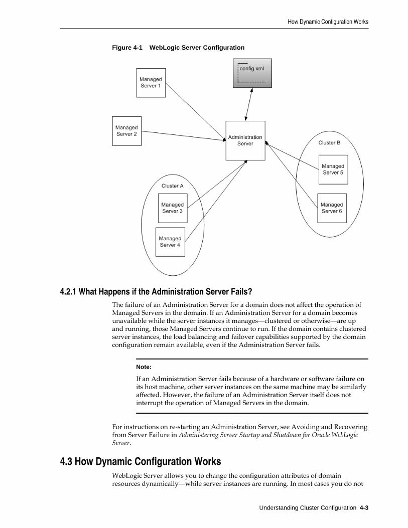
Figure 4-1 WebLogic Server Configuration
4.2.1 What Happens if the Administration Server Fails?The failure of an Administration Server for a domain does not affect the operation ofManaged Servers in the domain. If an Administration Server for a domain becomesunavailable while the server instances it manages—clustered or otherwise—are upand running, those Managed Servers continue to run. If the domain contains clusteredserver instances, the load balancing and failover capabilities supported by the domainconfiguration remain available, even if the Administration Server fails.
Note:
If an Administration Server fails because of a hardware or software failure onits host machine, other server instances on the same machine may be similarlyaffected. However, the failure of an Administration Server itself does notinterrupt the operation of Managed Servers in the domain.
For instructions on re-starting an Administration Server, see Avoiding and Recoveringfrom Server Failure in Administering Server Startup and Shutdown for Oracle WebLogicServer.
4.3 How Dynamic Configuration WorksWebLogic Server allows you to change the configuration attributes of domainresources dynamically—while server instances are running. In most cases you do not
How Dynamic Configuration Works
Understanding Cluster Configuration 4-3
need to restart the server instance for your changes to take effect. When an attribute isreconfigured, the new value is immediately reflected in both the current run-timevalue of the attribute and the persistent value stored in config.xml.
Not all configuration changes are applied dynamically. For example, if you change aManaged Server's ListenPort value, the new port will not be used until the nexttime you start the Managed Server. The updated value is stored in config.xml, butthe runtime value is not affected.
The WebLogic Server Administration Console validates attribute changes, checkingfor out-of-range errors and data type mismatch errors, and displays an error messagefor erroneous entries.
Once the WebLogic Server Administration Console has been started, if anotherprocess captures the listen port assigned to the Administration Server, you shouldstop the process that captured the port. If you are not able to remove the process thatcaptured the listen port, edit the config.xml file to change the ListenPort value.
4.4 Application Deployment for Clustered ConfigurationsThis section is brief introduction to the application deployment process. For moreinformation about deployment, see Deploying Applications to Oracle WebLogic Server.
For instructions on how to perform common deployment tasks, see DeployApplications.
4.4.1 Deployment MethodsYou can deploy an application to a cluster using following methods:
• WebLogic Server Administration Console
The WebLogic Server Administration Console is a graphical user interface (GUI) tothe Administration Service.
• weblogic.Deployer
The weblogic.Deployer utility is a Java-based deployment tool that provides acommand-line interface to the WebLogic Server deployment API.
• WebLogic Scripting Tool
The WebLogic Scripting Tool (WLST) is a command-line interface that you can useto automate domain configuration tasks, including application deploymentconfiguration and deployment operations.
These deployment tools are discussed in Deployment Tools in Deploying Applications toOracle WebLogic Server.
Regardless of the deployment tool you use, when you initiate the deployment processyou specify the components to be deployed, and the targets to which they will bedeployed—your cluster, or individual server instances within the cluster or domain.
The Administration Server for the domain manages the deployment process,communicating with the Managed Servers in the cluster throughout the process. EachManaged Server downloads components to be deployed, and initiates localdeployment tasks. The deployment state is maintained in the relevant MBeans for thecomponent being deployed. For more information, see Deployment Management API.
Application Deployment for Clustered Configurations
4-4 Administering Clusters for Oracle WebLogic Server
Note:
You must package applications before you deploy them to WebLogic Server.For more information, see the packaging topic in Deploying and Packagingfrom a Split Development Directory in Developing Applications for OracleWebLogic Server.
4.4.2 Introduction to Two-Phase DeploymentIn WebLogic Server, applications are deployed in two phases. Before starting,WebLogic Server determines the availability of the Managed Servers in the cluster.
4.4.2.1 First Phase of Deployment
During the first phase of deployment, application components are distributed to thetarget server instances, and the planned deployment is validated to ensure that theapplication components can be successfully deployed. During this phase, userrequests to the application being deployed are not allowed.
Failures encountered during the distribution and validation process will result in thedeployment being aborted on all server instances—including those upon which thevalidation succeeded. Files that have been staged will not be removed; however,container-side changes performed during the preparation will be reverted.
4.4.2.2 Second Phase of Deployment
After the application components have been distributed to targets and validated, theyare fully deployed on the target server instances, and the deployed application ismade available to clients.
When a failure is encountered during the second phase of deployment, the serverstarts with one of the following behaviors:
• If a failure occurs while deploying to the target server instances, the server instancewill start in ADMIN state. See ADMIN State in Administering Server Startup andShutdown for Oracle WebLogic Server.
• If cluster member fails to deploy an application, the application that failed todeploy is made unavailable.
4.4.3 Guidelines for Deploying to a ClusterIdeally, all Managed Servers in a cluster should be running and available during thedeployment process. Deploying applications while some members of the cluster areunavailable is not recommended. Before deploying applications to a cluster, ensure, ifpossible, that all Managed Servers in the cluster are running and reachable by theAdministration Server.
Application Deployment for Clustered Configurations
Understanding Cluster Configuration 4-5
Note:
If you deploy an application to a Managed Server that is partitioned at thetime of deployment—running but not reachable by the Administration Server—problems accessing the Managed Server can occur when that ManagedServer rejoins the cluster. During the synchronization period, while otherclustered Managed Servers re-establish communications with the previouslypartitioned server instance, user requests to the deployed applications andattempts to create secondary sessions on that server instance will fail. The riskof this circumstance occurring can be reduced by settingClusterConstraintsEnabled, as described in Enforcing ConsistentDeployment to All Configured Cluster Members in Deploying Applications toOracle WebLogic Server.
Cluster membership should not change during the deployment process. Afterinitiating deployment, do not:
• add or remove Managed Servers to the target cluster
• shut down Managed Servers in the target cluster
4.4.3.1 WebLogic Server Supports "Relaxed Deployment" Rules
Previous versions of WebLogic Server imposed these restrictions on deployment toclusters:
• No partial deployment—If one or more of the Managed Servers in the cluster areunavailable, the deployment process is terminated, and an error message isgenerated, indicating that unreachable Managed Servers should be either restartedor removed from the cluster before attempting deployment.
• Pinned services cannot be deployed to multiple Managed Servers in a cluster—Ifan application is not deployed to the cluster, you can deploy it to one and only oneManaged Server in the cluster.
4.4.3.1.1 Deployment to a Partial Cluster is Allowed
By default, WebLogic Server allows deployment to a partial cluster. If one or more ofthe Managed Servers in the cluster are unavailable, the following message may bedisplayed:
Unable to contact "servername". Deployment is deferred until "servername" becomes available.
When the unreachable Managed Server becomes available, deployment to that serverinstance will be initiated. Until the deployment process is completed, the ManagedServer may experience failures related to missing or out-of-date classes.
4.4.3.1.2 Deploying to Complete Clusters in WebLogic Server
You can ensure that deployment is only performed if all Managed Servers in thecluster are reachable by setting ClusterConstraintsEnabled. WhenClusterConstraintsEnabled is set to "true", a deployment to a cluster succeedsonly if all members of the cluster are reachable and all can deploy the specified files.See Enforcing Consistent Deployment to All Configured Cluster Members in DeployingApplications to Oracle WebLogic Server.
Application Deployment for Clustered Configurations
4-6 Administering Clusters for Oracle WebLogic Server
4.4.3.1.3 Pinned Services can be Deployed to Multiple Managed Servers.
It is possible to target a pinned service to multiple Managed Servers in a cluster. Thispractice is not recommended. The load-balancing capabilities and scalability of yourcluster can be negatively affected by deploying a pinned service to multiple ManagedServers in a cluster. If you target a pinned service to multiple Managed Servers, thefollowing message is printed to the server logs:
Adding server servername of cluster clustername as a target formodule modulename. This module also includes server servername thatbelongs to this cluster as one of its other targets. Having multipleindividual servers in a cluster as targets instead of having the entirecluster as the target can result in non-optimal load balancing andscalability. Hence this is not usually recommended.
4.5 Methods of Configuring ClustersThere are several methods for configuring a clusters:
• Configuration Wizard
The Configuration Wizard is the recommended tool for creating a new domain orcluster. See Introduction in Creating WebLogic Domains Using the ConfigurationWizard. See Clusters for information about creating and configuring a cluster.
• WebLogic Server Administration Console
The WebLogic Server Administration Console is a graphical user interface (GUI) tothe Administration Service. It allows you to perform a variety of domainconfiguration and monitoring functions.
• WebLogic Server Application Programming Interface (API)
You can write a program to modify the configuration attributes, based on theconfiguration application programming interface (API) provided with WebLogicServer. This method is not recommended for initial cluster implementation.
• WebLogic Scripting Tool (WLST)
The WebLogic Scripting Tool (WLST) is a command-line scripting interface thatsystem administrators and operators use to monitor and manage WebLogic Serverinstances and domains. For more information, see Understanding the WebLogicScripting Tool.
• Java Management Extensions (JMX)
JMX is the Java EE solution for monitoring and managing resources on a network.WebLogic Server provides a set of MBeans that you can use to configure, monitor,and manage WebLogic Server resources through JMX.
Methods of Configuring Clusters
Understanding Cluster Configuration 4-7

Methods of Configuring Clusters
4-8 Administering Clusters for Oracle WebLogic Server
5Load Balancing in a Cluster
This chapter describes the load balancing support that a WebLogic Server clusterprovides for different types of objects, and related planning and configurationconsiderations for architects and administrators.
This chapter contains the following sections:
• Load Balancing for Servlets and JSPs
• Load Balancing for EJBs and RMI Objects
• Load Balancing for JMS
For information about replication and failover in a cluster, see Failover andReplication in a Cluster.
For information about load balancing with the ReadyApp framework, see Using theReadyApp Framework in Deploying Applications to Oracle WebLogic Server.
5.1 Load Balancing for Servlets and JSPsYou can accomplish load balancing of servlets and JSPs with the built-in loadbalancing capabilities of a WebLogic proxy plug-in or with separate load balancinghardware.
Note:
In addition to distributing HTTP traffic, external load balancers can distributeinitial context requests that come from Java clients over t3 and the defaultchannel. See Load Balancing for EJBs and RMI Objects for a discussion ofobject-level load balancing in WebLogic Server.
5.1.1 Load Balancing with a Proxy Plug-inThe WebLogic proxy plug-in maintains a list of WebLogic Server instances that host aclustered servlet or JSP, and forwards HTTP requests to those instances on a round-robin basis. This load balancing method is described in Round-Robin Load Balancing.
The plug-in also provides the logic necessary to locate the replica of a client's HTTPsession state if a WebLogic Server instance should fail.
WebLogic Server supports the following Web servers and associated proxy plug-ins:
• WebLogic Server with the HttpClusterServlet
• Netscape Enterprise Server with the Netscape (proxy) plug-in
• Apache with the Apache Server (proxy) plug-in
Load Balancing in a Cluster 5-1
• Microsoft Internet Information Server with the Microsoft-IIS (proxy) plug-in
For instructions on setting up proxy plug-ins, see Configure Proxy Plug-Ins.
5.1.1.1 How Session Connection and Failover Work with a Proxy Plug-in
For a description of connection and failover for HTTP sessions in a cluster with proxyplug-ins, see Accessing Clustered Servlets and JSPs Using a Proxy.
5.1.2 Load Balancing HTTP Sessions with an External Load BalancerClusters that employ a hardware load balancing solution can use any load balancingalgorithm supported by the hardware. These can include advanced load-basedbalancing strategies that monitor the utilization of individual machines.
5.1.2.1 Load Balancer Configuration Requirements
If you choose to use load balancing hardware instead of a proxy plug-in, it mustsupport a compatible passive or active cookie persistence mechanism, and SSLpersistence.
• Passive Cookie Persistence
Passive cookie persistence enables WebLogic Server to write a cookie containingsession parameter information through the load balancer to the client. Forinformation about the session cookie and how a load balancer uses sessionparameter data to maintain the relationship between the client and the primaryWebLogic Server hosting a HTTP session state, see Load Balancers and theWebLogic Session Cookie.
• Active Cookie Persistence
You can use certain active cookie persistence mechanisms with WebLogic Serverclusters, provided the load balancer does not modify the WebLogic Server cookie.WebLogic Server clusters do not support active cookie persistence mechanisms thatoverwrite or modify the WebLogic HTTP session cookie. If the load balancer'sactive cookie persistence mechanism works by adding its own cookie to the clientsession, no additional configuration is required to use the load balancer with aWebLogic Server cluster.
• SSL Persistence
When SSL persistence is used, the load balancer performs all encryption anddecryption of data between clients and the WebLogic Server cluster. The loadbalancer then uses the plain text cookie that WebLogic Server inserts on the clientto maintain an association between the client and a particular server in the cluster.
5.1.2.2 Load Balancers and the WebLogic Session Cookie
A load balancer that uses passive cookie persistence can use a string in the WebLogicsession cookie to associate a client with the server hosting its primary HTTP sessionstate. The string uniquely identifies a server instance in the cluster. You mustconfigure the load balancer with the offset and length of the string constant. Thecorrect values for the offset and length depend on the format of the session cookie.
The format of a session cookie is:
sessionid!primary_server_id!secondary_server_id
where:
Load Balancing for Servlets and JSPs
5-2 Administering Clusters for Oracle WebLogic Server
• sessionid is a randomly generated identifier of the HTTP session. The length ofthe value is configured by the IDLength parameter in the <session-descriptor> element in the weblogic.xml file for an application. By default,the sessionid length is 52 bytes.
• primary_server_id and secondary_server_id are 10 character identifiers ofthe primary and secondary hosts for the session.
Note:
For sessions using non-replicated memory, cookie, or file-based sessionpersistence, the secondary_server_id is not present. For sessions that usein-memory replication, if the secondary session does not exist, thesecondary_server_id is "NONE".
For general instructions on configuring load balancers, see Configuring LoadBalancers that Support Passive Cookie Persistence. Instructions for configuring BIG-IP,see Configuring BIG-IP Hardware with Clusters.
5.1.2.3 Related Programming Considerations
For programming constraints and recommendations for clustered servlets and JSPs,see Programming Considerations for Clustered Servlets and JSPs.
5.1.2.4 How Session Connection and Failover Works with a Load Balancer
For a description of connection and failover for HTTP sessions in a cluster with loadbalancing hardware, see Accessing Clustered Servlets and JSPs with Load BalancingHardware.
5.2 Load Balancing for EJBs and RMI ObjectsThis section describes WebLogic Server load balancing algorithms for EJBs and RMIobjects.
The load balancing algorithm for an object is maintained in the replica-aware stubobtained for a clustered object.
By default, WebLogic Server clusters use round-robin load balancing, described in Round-Robin Load Balancing. You can configure a different default load balancingmethod for a cluster by using the WebLogic Server Administration Console to setweblogic.cluster.defaultLoadAlgorithm. For instructions, see ConfigureLoad Balancing Method for EJBs and RMIs. You can also specify the load balancingalgorithm for a specific RMI object using the -loadAlgorithm option in rmic, orwith the home-load-algorithm or stateless-bean-load-algorithm in anEJB's deployment descriptor. A load balancing algorithm that you configure for anobject overrides the default load balancing algorithm for the cluster.
In addition to the standard load balancing algorithms, WebLogic Server supportscustom parameter-based routing. For more information, see Parameter-Based Routingfor Clustered Objects.
Also, external load balancers can distribute initial context requests that come fromJava clients over t3 and the default channel. However, because WebLogic Server loadbalancing for EJBs and RMI objects is controlled via replica-aware stubs, includingsituations where server affinity is employed, you should not route client requests,following the initial context request, through the load balancers. When using the t3protocol with external load balancers, you must ensure that only the initial context
Load Balancing for EJBs and RMI Objects
Load Balancing in a Cluster 5-3
request is routed through the load balancers, and that subsequent requests are routedand controlled using WebLogic Server load balancing.
Oracle advises against using the t3s protocol with external load balancers. In caseswhere the use of t3 and SSL with external load balancers is required, Oraclerecommends using t3 tunneling through HTTPS. In cases where server affinity isrequired, you must use HTTP session IDs for routing requests, and must terminateSSL at the load balancer performing session-based routing to enable appropriaterouting of requests based on session IDs.
5.2.1 Round-Robin Load BalancingWebLogic Server uses the round-robin algorithm as the default load balancingstrategy for clustered object stubs when no algorithm is specified. This algorithm issupported for RMI objects and EJBs. It is also the method used by WebLogic proxyplug-ins.
The round-robin algorithm cycles through a list of WebLogic Server instances in order.For clustered objects, the server list consists of WebLogic Server instances that host theclustered object. For proxy plug-ins, the list consists of all WebLogic Server instancesthat host the clustered servlet or JSP.
The advantages of the round-robin algorithm are that it is simple, cheap and verypredictable. The primary disadvantage is that there is some chance of convoying.Convoying occurs when one server is significantly slower than the others. Becausereplica-aware stubs or proxy plug-ins access the servers in the same order, a slowserver can cause requests to "synchronize" on the server, then follow other servers inorder for future requests.
Note:
WebLogic Server does not always load balance an object's method calls. Formore information, see Optimization for Collocated Objects.
5.2.2 Weight-Based Load BalancingThis algorithm applies only to EJB and RMI object clustering.
Weight-based load balancing improves on the round-robin algorithm by taking intoaccount a pre-assigned weight for each server. You can use the Server >Configuration > Cluster page in the WebLogic Server Administration Console toassign each server in the cluster a numerical weight between 1 and 100, in theCluster Weight field. This value determines what proportion of the load the serverwill bear relative to other servers. If all servers have the same weight, they will eachbear an equal proportion of the load. If one server has weight 50 and all other servershave weight 100, the 50-weight server will bear half as much as any other server. Thisalgorithm makes it possible to apply the advantages of the round-robin algorithm toclusters that are not homogeneous.
If you use the weight-based algorithm, carefully determine the relative weights toassign to each server instance. Factors to consider include:
• The processing capacity of the server's hardware in relationship to other servers(for example, the number and performance of CPUs dedicated to WebLogicServer).
• The number of non-clustered ("pinned") objects each server hosts.
Load Balancing for EJBs and RMI Objects
5-4 Administering Clusters for Oracle WebLogic Server
If you change the specified weight of a server and reboot it, the new weightinginformation is propagated throughout the cluster via the replica-aware stubs. Forrelated information see Cluster-Wide JNDI Naming Service.
Note:
WebLogic Server does not always load balance an object's method calls. Formore information, see Optimization for Collocated Objects.
In this version of WebLogic Server, weight-based load balancing is notsupported for objects that communicate using the RMI/IIOP protocol.
5.2.3 Random Load BalancingThe random method of load balancing applies only to EJB and RMI object clustering.
In random load balancing, requests are routed to servers at random. Random loadbalancing is recommended only for homogeneous cluster deployments, where eachserver instance runs on a similarly configured machine. A random allocation ofrequests does not allow for differences in processing power among the machines uponwhich server instances run. If a machine hosting servers in a cluster has significantlyless processing power than other machines in the cluster, random load balancing willgive the less powerful machine as many requests as it gives more powerful machines.
Random load balancing distributes requests evenly across server instances in thecluster, increasingly so as the cumulative number of requests increases. Over a smallnumber of requests the load may not be balanced exactly evenly.
Disadvantages of random load balancing include the slight processing overheadincurred by generating a random number for each request, and the possibility that theload may not be evenly balanced over a small number of requests.
Note:
WebLogic Server does not always load balance an object's method calls. Formore information, see Optimization for Collocated Objects.
5.2.4 Server Affinity Load Balancing AlgorithmsWebLogic Server provides three load balancing algorithms for RMI objects thatprovide server affinity. Server affinity turns off load balancing for external clientconnections; instead, the client considers its existing connections to WebLogic Serverinstances when choosing the server instance on which to access an object. If an objectis configured for server affinity, the client-side stub attempts to choose a serverinstance to which it is already connected, and continues to use the same serverinstance for method calls. All stubs on that client attempt to use that server instance. Ifthe server instance becomes unavailable, the stubs fail over, if possible, to a serverinstance to which the client is already connected.
The purpose of server affinity is to minimize the number IP sockets opened betweenexternal Java clients and server instances in a cluster. WebLogic Server accomplishesthis by causing method calls on objects to "stick" to an existing connection, instead ofbeing load balanced among the available server instances. With server affinityalgorithms, the less costly server-to-server connections are still load-balanced
Load Balancing for EJBs and RMI Objects
Load Balancing in a Cluster 5-5
according to the configured load balancing algorithm—load balancing is disabled onlyfor external client connections.
Server affinity is used in combination with one of the standard load balancingmethods: round-robin, weight-based, or random:
• round-robin-affinity—server affinity governs connections between external Javaclients and server instances; round-robin load balancing is used for connectionsbetween server instances.
• weight-based-affinity—server affinity governs connections between external Javaclients and server instances; weight-based load balancing is used for connectionsbetween server instances.
• random-affinity—server affinity governs connections between external Java clientsand server instances; random load balancing is used for connections betweenserver instances.
5.2.4.1 Server Affinity and Initial Context
A client can request an initial context from a particular server instance in the cluster, orfrom the cluster by specifying the cluster address in the URL. The connection processvaries, depending on how the context is obtained:
• If the initial context is requested from a specific Managed Server, the context isobtained using a new connection to the specified server instance.
• If the initial context is requested from a cluster, by default, context requests areload balanced on a round-robin basis among the clustered server instances. Toreuse an existing connection between a particular JVM and the cluster, setENABLE_SERVER_AFFINITY to true in the hash table ofweblogic.jndi.WLContext properties you specify when obtaining context. (If aconnection is not available, a new connection is created.)ENABLE_SERVER_AFFINITY is only supported when the context is requestedfrom the cluster address.
5.2.4.2 Server Affinity and IIOP Client Authentication Using CSIv2
If you use WebLogic Server Common Secure Interoperability (CSIv2) functionality tosupport stateful interactions with the WebLogic Server Java EE Application Client("thin client"), you must use an affinity-based load balancing algorithm to ensure thatmethod calls stick to a server instance. Otherwise, all remote calls will beauthenticated. To prevent redundant authentication of stateful CSIv2 clients, use oneof the load balancing algorithms described in Round-Robin Affinity_ Weight-BasedAffinity_ and Random-Affinity.
5.2.4.3 Round-Robin Affinity, Weight-Based Affinity, and Random-Affinity
WebLogic Server has three load balancing algorithms that provide server affinity:
• round-robin-affinity
• weight-based-affinity
• random-affinity
Server affinity is supported for all types of RMI objects including JMS objects, all EJBhome interfaces, and stateless EJB remote interfaces.
Load Balancing for EJBs and RMI Objects
5-6 Administering Clusters for Oracle WebLogic Server
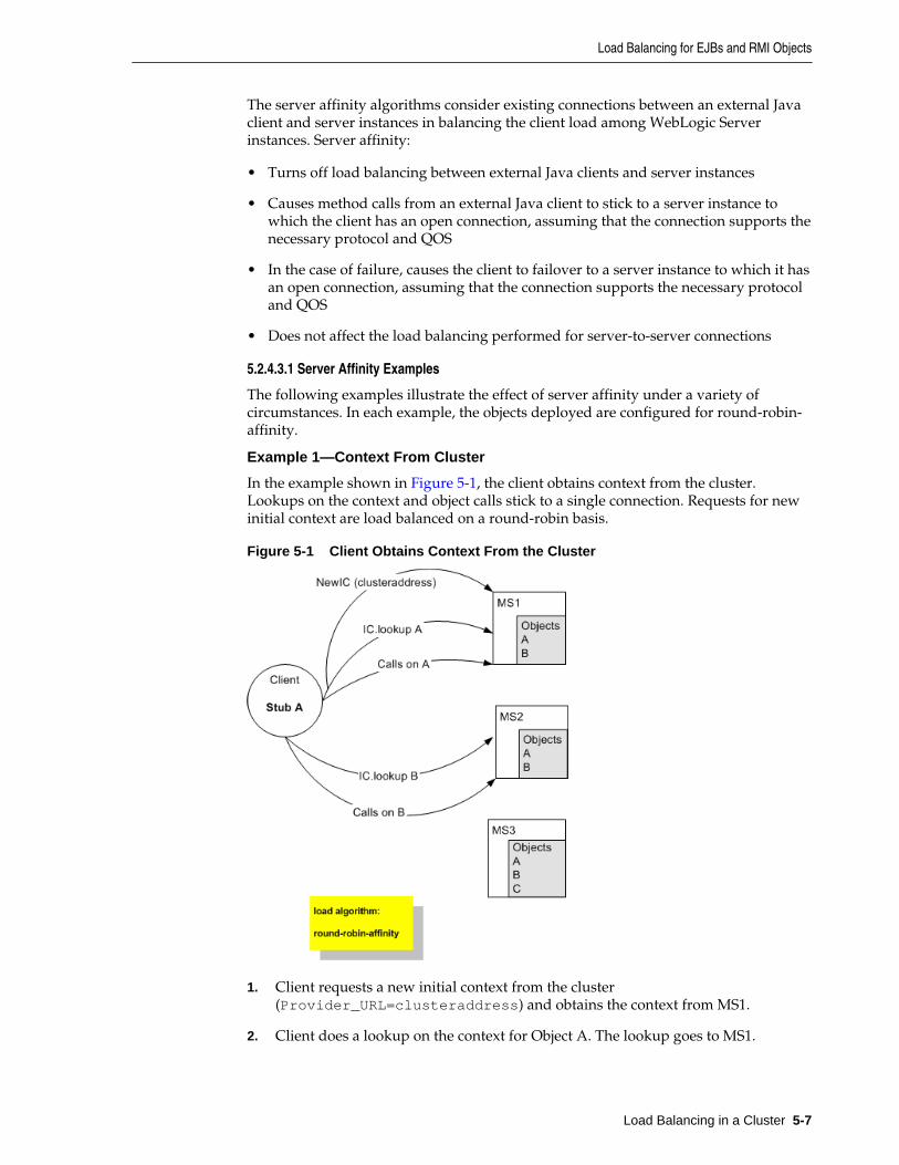
The server affinity algorithms consider existing connections between an external Javaclient and server instances in balancing the client load among WebLogic Serverinstances. Server affinity:
• Turns off load balancing between external Java clients and server instances
• Causes method calls from an external Java client to stick to a server instance towhich the client has an open connection, assuming that the connection supports thenecessary protocol and QOS
• In the case of failure, causes the client to failover to a server instance to which it hasan open connection, assuming that the connection supports the necessary protocoland QOS
• Does not affect the load balancing performed for server-to-server connections
5.2.4.3.1 Server Affinity Examples
The following examples illustrate the effect of server affinity under a variety ofcircumstances. In each example, the objects deployed are configured for round-robin-affinity.
Example 1—Context From Cluster
In the example shown in Figure 5-1, the client obtains context from the cluster.Lookups on the context and object calls stick to a single connection. Requests for newinitial context are load balanced on a round-robin basis.
Figure 5-1 Client Obtains Context From the Cluster
1. Client requests a new initial context from the cluster(Provider_URL=clusteraddress) and obtains the context from MS1.
2. Client does a lookup on the context for Object A. The lookup goes to MS1.
Load Balancing for EJBs and RMI Objects
Load Balancing in a Cluster 5-7
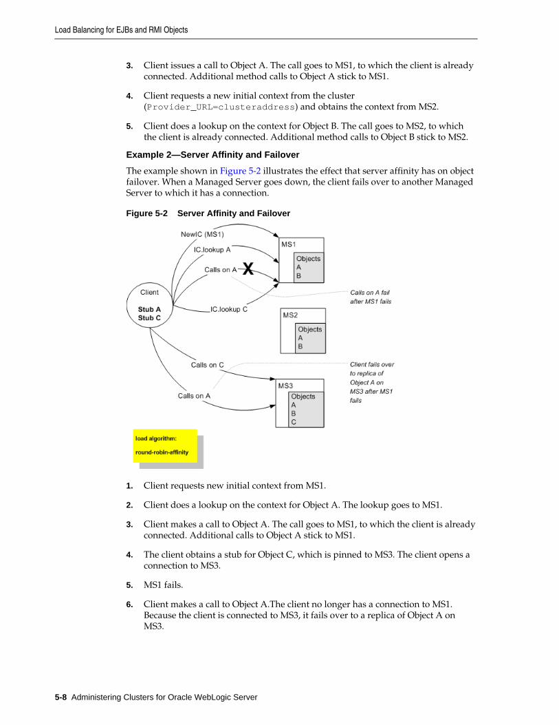
3. Client issues a call to Object A. The call goes to MS1, to which the client is alreadyconnected. Additional method calls to Object A stick to MS1.
4. Client requests a new initial context from the cluster(Provider_URL=clusteraddress) and obtains the context from MS2.
5. Client does a lookup on the context for Object B. The call goes to MS2, to whichthe client is already connected. Additional method calls to Object B stick to MS2.
Example 2—Server Affinity and Failover
The example shown in Figure 5-2 illustrates the effect that server affinity has on objectfailover. When a Managed Server goes down, the client fails over to another ManagedServer to which it has a connection.
Figure 5-2 Server Affinity and Failover
1. Client requests new initial context from MS1.
2. Client does a lookup on the context for Object A. The lookup goes to MS1.
3. Client makes a call to Object A. The call goes to MS1, to which the client is alreadyconnected. Additional calls to Object A stick to MS1.
4. The client obtains a stub for Object C, which is pinned to MS3. The client opens aconnection to MS3.
5. MS1 fails.
6. Client makes a call to Object A.The client no longer has a connection to MS1.Because the client is connected to MS3, it fails over to a replica of Object A onMS3.
Load Balancing for EJBs and RMI Objects
5-8 Administering Clusters for Oracle WebLogic Server
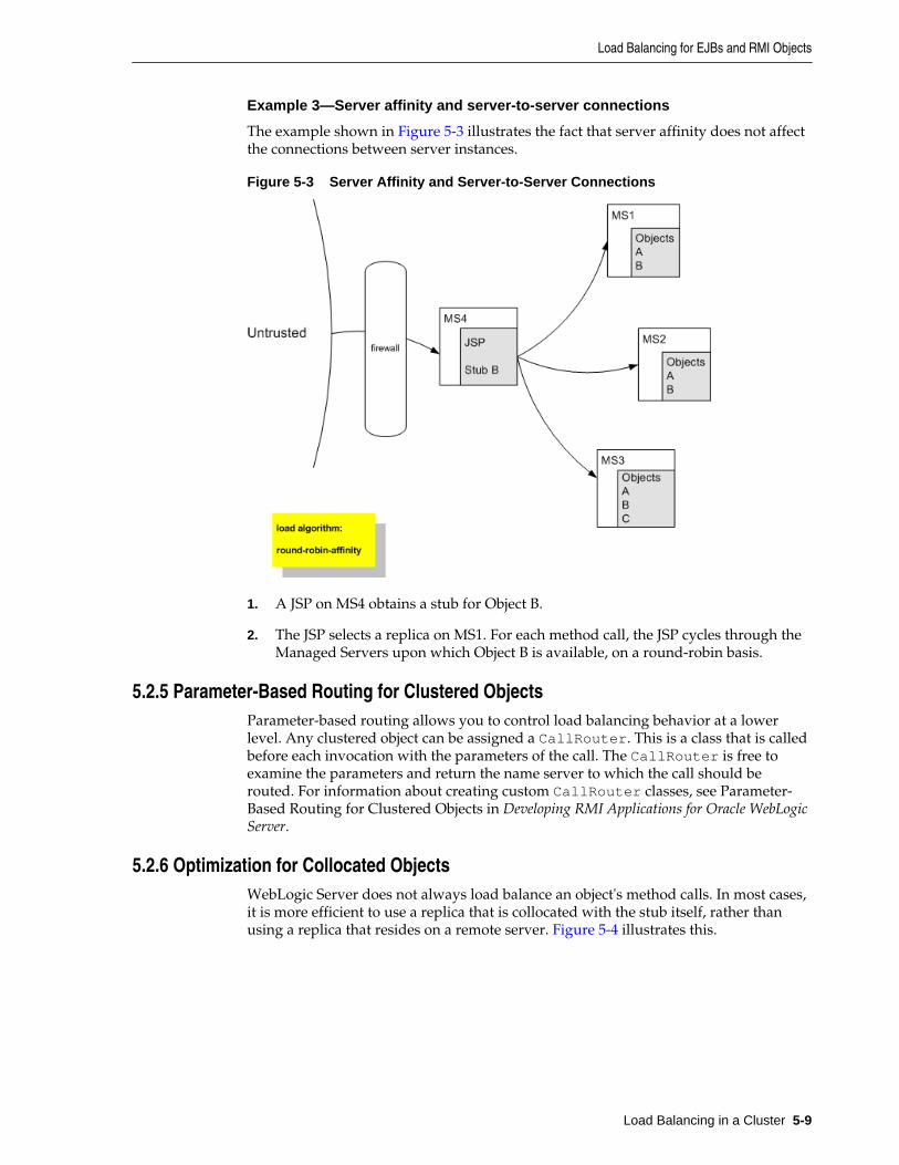
Example 3—Server affinity and server-to-server connections
The example shown in Figure 5-3 illustrates the fact that server affinity does not affectthe connections between server instances.
Figure 5-3 Server Affinity and Server-to-Server Connections
1. A JSP on MS4 obtains a stub for Object B.
2. The JSP selects a replica on MS1. For each method call, the JSP cycles through theManaged Servers upon which Object B is available, on a round-robin basis.
5.2.5 Parameter-Based Routing for Clustered ObjectsParameter-based routing allows you to control load balancing behavior at a lowerlevel. Any clustered object can be assigned a CallRouter. This is a class that is calledbefore each invocation with the parameters of the call. The CallRouter is free toexamine the parameters and return the name server to which the call should berouted. For information about creating custom CallRouter classes, see Parameter-Based Routing for Clustered Objects in Developing RMI Applications for Oracle WebLogicServer.
5.2.6 Optimization for Collocated ObjectsWebLogic Server does not always load balance an object's method calls. In most cases,it is more efficient to use a replica that is collocated with the stub itself, rather thanusing a replica that resides on a remote server. Figure 5-4 illustrates this.
Load Balancing for EJBs and RMI Objects
Load Balancing in a Cluster 5-9
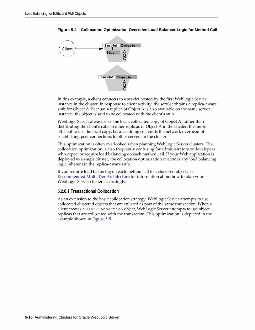
Figure 5-4 Collocation Optimization Overrides Load Balancer Logic for Method Call
In this example, a client connects to a servlet hosted by the first WebLogic Serverinstance in the cluster. In response to client activity, the servlet obtains a replica-awarestub for Object A. Because a replica of Object A is also available on the same serverinstance, the object is said to be collocated with the client's stub.
WebLogic Server always uses the local, collocated copy of Object A, rather thandistributing the client's calls to other replicas of Object A in the cluster. It is moreefficient to use the local copy, because doing so avoids the network overhead ofestablishing peer connections to other servers in the cluster.
This optimization is often overlooked when planning WebLogic Server clusters. Thecollocation optimization is also frequently confusing for administrators or developerswho expect or require load balancing on each method call. If your Web application isdeployed to a single cluster, the collocation optimization overrides any load balancinglogic inherent in the replica-aware stub.
If you require load balancing on each method call to a clustered object, see Recommended Multi-Tier Architecture for information about how to plan yourWebLogic Server cluster accordingly.
5.2.6.1 Transactional Collocation
As an extension to the basic collocation strategy, WebLogic Server attempts to usecollocated clustered objects that are enlisted as part of the same transaction. When aclient creates a UserTransaction object, WebLogic Server attempts to use objectreplicas that are collocated with the transaction. This optimization is depicted in theexample shown in Figure 5-5.
Load Balancing for EJBs and RMI Objects
5-10 Administering Clusters for Oracle WebLogic Server
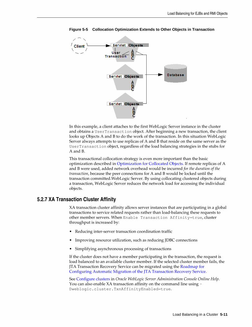
Figure 5-5 Collocation Optimization Extends to Other Objects in Transaction
In this example, a client attaches to the first WebLogic Server instance in the clusterand obtains a UserTransaction object. After beginning a new transaction, the clientlooks up Objects A and B to do the work of the transaction. In this situation WebLogicServer always attempts to use replicas of A and B that reside on the same server as theUserTransaction object, regardless of the load balancing strategies in the stubs forA and B.
This transactional collocation strategy is even more important than the basicoptimization described in Optimization for Collocated Objects. If remote replicas of Aand B were used, added network overhead would be incurred for the duration of thetransaction, because the peer connections for A and B would be locked until thetransaction committed.WebLogic Server. By using collocating clustered objects duringa transaction, WebLogic Server reduces the network load for accessing the individualobjects.
5.2.7 XA Transaction Cluster AffinityXA transaction cluster affinity allows server instances that are participating in a globaltransactions to service related requests rather than load-balancing these requests toother member servers. When Enable Transaction Affinity=true, clusterthroughput is increased by:
• Reducing inter-server transaction coordination traffic
• Improving resource utilization, such as reducing JDBC connections
• Simplifying asynchronous processing of transactions
If the cluster does not have a member participating in the transaction, the request isload balanced to an available cluster member. If the selected cluster member fails, theJTA Transaction Recovery Service can be migrated using the Roadmap forConfiguring Automatic Migration of the JTA Transaction Recovery Service.
See Configure clusters in Oracle WebLogic Server Administration Console Online Help.You can also enable XA transaction affinity on the command line using -Dweblogic.cluster.TxnAffinityEnabled=true.
Load Balancing for EJBs and RMI Objects
Load Balancing in a Cluster 5-11
5.3 Load Balancing for JMSWebLogic Server JMS supports server affinity for distributed JMS destinations andclient connections.
By default, a WebLogic Server cluster uses the round-robin method to load balanceobjects. To use a load balancing algorithm that provides server affinity for JMS objects,you must configure the desired method for the cluster as a whole. You can configurethe load balancing algorithm by using the WebLogic Server Administration Console toset weblogic.cluster.defaultLoadAlgorithm. For instructions, see ConfigureLoad Balancing Method for EJBs and RMIs .
5.3.1 Server Affinity for Distributed JMS DestinationsServer affinity is supported for JMS applications that use the distributed destinationfeature; this feature is not supported for standalone destinations. If you configureserver affinity for JMS connection factories, a server instance that is load balancingconsumers or producers across multiple members of a distributed destination will firstattempt to load balance across any destination members that are also running on thesame server instance.
For detailed information on how the JMS connection factory's Server Affinity Enabledoption affects the load balancing preferences for distributed destination members, see How Distributed Destination Load Balancing Is Affected When Using the ServerAffinity Enabled Attribute in Administering JMS Resources for Oracle WebLogic Server.
5.3.2 Initial Context Affinity and Server Affinity for Client ConnectionsA system administrator can establish load balancing of JMS destinations acrossmultiple servers in a cluster by configuring multiple JMS servers and using targets toassign them to the defined WebLogic Servers. Each JMS server is deployed on exactlyone WebLogic Server and handles requests for a set of destinations. During theconfiguration phase, the system administrator enables load balancing by specifyingtargets for JMS servers. For instructions on setting up targets, see ConfigureMigratable Targets for Pinned Services. For instructions on deploying a JMS server toa migratable target, see Deploying_ Activating_ and Migrating Migratable Services.
A system administrator can establish cluster-wide, transparent access to destinationsfrom any server in the cluster by configuring multiple connection factories and usingtargets to assign them to WebLogic Servers. Each connection factory can be deployedon multiple WebLogic Servers. Connection factories are described in more detail in ConnectionFactory in Developing JMS Applications for Oracle WebLogic Server.
The application uses the Java Naming and Directory Interface (JNDI) to look up aconnection factory and create a connection to establish communication with a JMSserver. Each JMS server handles requests for a set of destinations. Requests fordestinations not handled by a JMS server are forwarded to the appropriate server.
WebLogic Server provides server affinity for client connections. If an application has aconnection to a given server instance, JMS will attempt to establish new JMSconnections to the same server instance.
When creating a connection, JMS will try first to achieve initial context affinity. It willattempt to connect to the same server or servers to which a client connected for itsinitial context, assuming that the server instance is configured for that connectionfactory. For example, if the connection factory is configured for servers A and B, but
Load Balancing for JMS
5-12 Administering Clusters for Oracle WebLogic Server

the client has an InitialContext on server C, then the connection factory will notestablish the new connection with A, but will choose between servers B and C.
If a connection factory cannot achieve initial context affinity, it will try to provideaffinity to a server to which the client is already connected. For instance, assume theclient has an InitialContext on server A and some other type of connection to server B.If the client then uses a connection factory configured for servers B and C it will notachieve initial context affinity. The connection factory will instead attempt to achieveserver affinity by trying to create a connection to server B, to which it already has aconnection, rather than server C.
If a connection factory cannot provide either initial context affinity or server affinity,then the connection factory is free to make a connection wherever possible. Forinstance, assume a client has an initial context on server A, no other connections and aconnection factory configured for servers B and C. The connection factory is unable toprovide any affinity and is free to attempt new connections to either server B or C.
Note:
In the last case, if the client attempts to make a second connection using thesame connection factory, it will go to the same server as it did on the firstattempt. That is, if it chose server B for the first connection, when the secondconnection is made, the client will have a connection to server B and the serveraffinity rule will be enforced.
Load Balancing for JMS
Load Balancing in a Cluster 5-13

Load Balancing for JMS
5-14 Administering Clusters for Oracle WebLogic Server
6Failover and Replication in a Cluster
This chapter describes how WebLogic Server detects failures in a cluster and providesan overview of how failover is accomplished for different types of objects.
This chapter includes the following sections:
• How WebLogic Server Detects Failures
• Replication and Failover for Servlets and JSPs
• Replication and Failover for EJBs and RMIs
This chapter focuses on failover and replication at the application level. WebLogicServer also supports automatic migration of server instances and services after failure.For more information, see Whole Server Migration.
6.1 How WebLogic Server Detects FailuresWebLogic Server instances in a cluster detect failures of their peer server instances bymonitoring:
• Socket connections to a peer server
• Regular server heartbeat messages
6.1.1 Failure Detection Using IP SocketsWebLogic Server instances monitor the use of IP sockets between peer server instancesas an immediate method of detecting failures. If a server connects to one of its peers ina cluster and begins transmitting data over a socket, an unexpected closure of thatsocket causes the peer server to be marked as "failed," and its associated services areremoved from the JNDI naming tree.
6.1.2 The WebLogic Server "Heartbeat"If clustered server instances do not have opened sockets for peer-to-peercommunication, failed servers may also be detected via the WebLogic Serverheartbeat. All server instances in a cluster use multicast or unicast to broadcast regularserver heartbeat messages to other members of the cluster.
Each heartbeat message contains data that uniquely identifies the server that sends themessage. Servers broadcast their heartbeat messages at regular intervals of 10 seconds.In turn, each server in a cluster monitors the multicast or unicast address to ensurethat all peer servers' heartbeat messages are being sent.
If a server monitoring the multicast or unicast address misses three heartbeats from apeer server (for example, if it does not receive a heartbeat from the server for 30seconds or longer), the monitoring server marks the peer server as "failed." It then
Failover and Replication in a Cluster 6-1
updates its local JNDI tree, if necessary, to retract the services that were hosted on thefailed server.
In this way, servers can detect failures even if they have no sockets open for peer-to-peer communication.
Note:
The default cluster messaging mode is unicast.
For more information about how WebLogic Server uses IP sockets and eithermulticast or unicast communications see Communications In a Cluster.
6.2 Replication and Failover for Servlets and JSPsTo support automatic replication and failover for servlets and JSPs within a cluster,Weblogic Server supports two mechanisms for preserving HTTP session state:
• Hardware load balancers
For clusters that use a supported hardware load balancing solution, the loadbalancing hardware simply redirects client requests to any available server in theWebLogic Server cluster. The cluster itself obtains the replica of the client's HTTPsession state from a secondary server in the cluster.
• Proxy plug-ins
For clusters that use a supported Web server and WebLogic plug-in, the plug-inredirects client requests to any available server instance in the WebLogic Servercluster. The cluster obtains the replica of the client's HTTP session state from eitherthe primary or secondary server instance in the cluster.
This section covers the following topics:
• HTTP Session State Replication
• Accessing Clustered Servlets and JSPs Using a Proxy
• Accessing Clustered Servlets and JSPs with Load Balancing Hardware
• Session State Replication Across Clusters in a MAN/WAN
6.2.1 HTTP Session State ReplicationWebLogic Server provides three methods for replicating HTTP session state acrossclusters:
• In-memory replication
Using in-memory replication, WebLogic Server copies a session state from oneserver instance to another. The primary server creates a primary session state onthe server to which the client first connects, and a secondary replica on anotherWebLogic Server instance in the cluster. The replica is kept up-to-date so that itmay be used if the server that hosts the servlet fails.
• JDBC-based persistence
In JDBC-based persistence, WebLogic Server maintains the HTTP session state of aservlet or JSP using file-based or JDBC-based persistence. For more information on
Replication and Failover for Servlets and JSPs
6-2 Administering Clusters for Oracle WebLogic Server
these persistence mechanisms, see Configuring Session Persistence in DevelopingWeb Applications, Servlets, and JSPs for Oracle WebLogic Server.
JDBC-based persistence is also used for HTTP session state replication within aWide Area Network (WAN). For more information, see WAN HTTP Session StateReplication.
Note:
Web applications which have persistent store type set to replicated orreplicated_if_clustered will have to be targeted to the cluster or all thenodes of that cluster. If it is targeted to only some nodes in the cluster, theWeb application will not be deployed. In-memory replication requires thatWeb applications be deployed homogeneously on all the nodes in a cluster.
• Coherence*Web
You can use Coherence*Web for session replication. Coherence*Web is not areplacement for WebLogic Server's in-memory HTTP state replication services.However, you should consider using Coherence*Web when an application haslarge HTTP session state objects, when running into memory constraints due tostoring HTTP session object data, or if you want to reuse an existing Coherencecluster.
For more information, see Administering HTTP Session Management with OracleCoherence*Web.
The following section describe session state replication using in-memory replication.
6.2.1.1 Requirements for HTTP Session State Replication
To use in-memory replication for HTTP session states, you must access the WebLogicServer cluster using either a collection of Web servers with identically configuredWebLogic proxy plug-ins, or load balancing hardware.
6.2.1.1.1 Supported Server and Proxy Software
The WebLogic proxy plug-in maintains a list of WebLogic Server instances that host aclustered servlet or JSP, and forwards HTTP requests to those instances using a round-robin strategy. The plug-in also provides the logic necessary to locate the replica of aclient's HTTP session state if a WebLogic Server instance should fail.
In-memory replication for HTTP session states is supported by the following Webservers and proxy software:
• WebLogic Server with the HttpClusterServlet
• Apache with the Apache Server (proxy) plug-in
• Microsoft Internet Information Server with the Microsoft-IIS (proxy) plug-in
For instructions on setting up proxy plug-ins, see Configure Proxy Plug-Ins.
6.2.1.1.2 Load Balancer Requirements
If you choose to use load balancing hardware instead of a proxy plug-in, it mustsupport a compatible passive or active cookie persistence mechanism, and SSLpersistence. For details on these requirements, see Load Balancer ConfigurationRequirements. For instructions on setting up a load balancer, see Configuring LoadBalancers that Support Passive Cookie Persistence.
Replication and Failover for Servlets and JSPs
Failover and Replication in a Cluster 6-3
6.2.1.1.3 Programming Considerations for Clustered Servlets and JSPs
This section highlights key programming constraints and recommendations forservlets and JSPs that you will deploy in a clustered environment.
• Session Data Must Be Serializable
To support in-memory replication of HTTP session states, all servlet and JSPsession data must be serializable.
Note:
Serialization is the process of converting a complex data structure, such as aparallel arrangement of data (in which a number of bits are transmitted at atime along parallel channels) into a serial form (in which one bit at a time istransmitted); a serial interface provides this conversion to enable datatransmission.
Every field in an object must be serializable or transient in order for the object to beconsidered serializable. If the servlet or JSP uses a combination of serializable andnon-serializable objects, WebLogic Server does not replicate the session state of thenon-serializable objects.
• Use setAttribute to Change Session State
In an HTTP servlet that implements javax.servlet.http.HttpSession, useHttpSession.setAttribute (which replaces the deprecated putValue) tochange attributes in a session object. If you set attributes in a session object withsetAttribute, the object and its attributes are replicated in a cluster using in-memory replication. If you use other set methods to change objects within asession, WebLogic Server does not replicate those changes. Every time a change ismade to an object that is in the session, setAttribute() should be called toupdate that object across the cluster.
Likewise, use removeAttribute (which, in turn, replaces the deprecatedremoveValue) to remove an attribute from a session object.
Note:
Use of the deprecated putValue and removeValue methods will also causesession attributes to be replicated.
• Consider Serialization Overhead
Serializing session data introduces some overhead for replicating the session state.The overhead increases as the size of serialized objects grows. If you plan to createvery large objects in the session, test the performance of your servlets to ensure thatperformance is acceptable.
• Control Frame Access to Session Data
If you are designing a Web application that utilizes multiple frames, keep in mindthat there is no synchronization of requests made by frames in a given frameset.For example, it is possible for multiple frames in a frameset to create multiplesessions on behalf of the client application, even though the client should logicallycreate only a single session.
Replication and Failover for Servlets and JSPs
6-4 Administering Clusters for Oracle WebLogic Server
In a clustered environment, poor coordination of frame requests can causeunexpected application behavior. For example, multiple frame requests can "reset"the application's association with a clustered instance, because the proxy plug-intreats each request independently. It is also possible for an application to corruptsession data by modifying the same session attribute via multiple frames in aframeset.
To avoid unexpected application behavior, carefully plan how you access sessiondata with frames. You can apply one of the following general rules to avoidcommon problems:
– In a given frameset, ensure that only one frame creates and modifies sessiondata.
– Always create the session in a frame of the first frameset your application uses(for example, create the session in the first HTML page that is visited). After thesession has been created, access the session data only in framesets other than thefirst frameset.
6.2.1.2 Using Replication Groups
By default, WebLogic Server attempts to create session state replicas on a differentmachine than the one that hosts the primary session state. You can further controlwhere secondary states are placed using replication groups. A replication group is apreferred list of clustered servers to be used for storing session state replicas.
Using the WebLogic Server Administration Console, you can define unique machinenames that will host individual server instances. These machine names can beassociated with new WebLogic Server instances to identify where the servers reside inyour system.
Machine names are generally used to indicate servers that run on the same machine.For example, you would assign the same machine name to all server instances that runon the same machine, or the same server hardware.
If you do not run multiple WebLogic Server instances on a single machine, you do notneed to specify WebLogic Server machine names. Servers without a machine name aretreated as though they reside on separate machines. For detailed instructions onsetting machine names, see Configure Machine Names.
When you configure a clustered server instance, you can assign the server to areplication group, and a preferred secondary replication group for hosting replicas ofthe primary HTTP session states created on the server.
When a client attaches to a server in the cluster and creates a primary session state, theserver hosting the primary state ranks other servers in the cluster to determine whichserver should host the secondary. Server ranks are assigned using a combination of theserver's location (whether or not it resides on the same machine as the primary server)and its participation in the primary server's preferred replication group. Table 6-1shows the relative ranking of servers in a cluster.
Table 6-1 Ranking Server Instances for Session Replication
Server Rank Server Resides on aDifferent Machine
Server is a Member of PreferredReplication Group
1 Yes Yes
2 No Yes
Replication and Failover for Servlets and JSPs
Failover and Replication in a Cluster 6-5
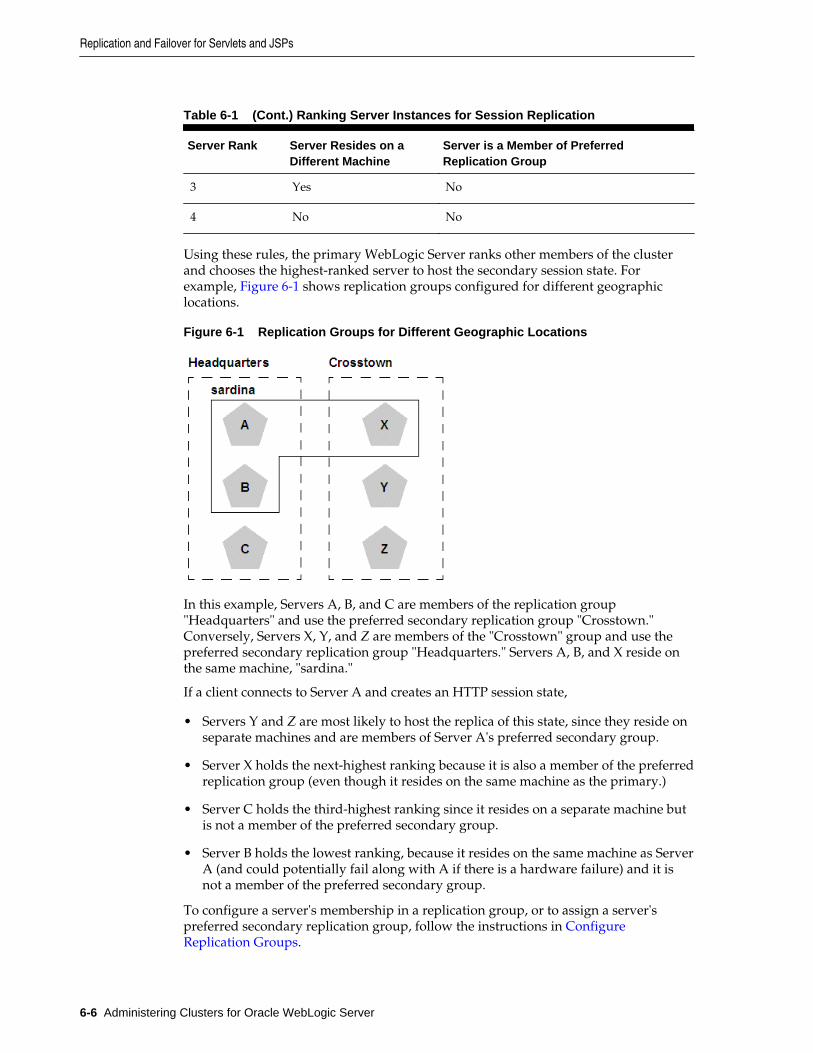
Table 6-1 (Cont.) Ranking Server Instances for Session Replication
Server Rank Server Resides on aDifferent Machine
Server is a Member of PreferredReplication Group
3 Yes No
4 No No
Using these rules, the primary WebLogic Server ranks other members of the clusterand chooses the highest-ranked server to host the secondary session state. Forexample, Figure 6-1 shows replication groups configured for different geographiclocations.
Figure 6-1 Replication Groups for Different Geographic Locations
In this example, Servers A, B, and C are members of the replication group"Headquarters" and use the preferred secondary replication group "Crosstown."Conversely, Servers X, Y, and Z are members of the "Crosstown" group and use thepreferred secondary replication group "Headquarters." Servers A, B, and X reside onthe same machine, "sardina."
If a client connects to Server A and creates an HTTP session state,
• Servers Y and Z are most likely to host the replica of this state, since they reside onseparate machines and are members of Server A's preferred secondary group.
• Server X holds the next-highest ranking because it is also a member of the preferredreplication group (even though it resides on the same machine as the primary.)
• Server C holds the third-highest ranking since it resides on a separate machine butis not a member of the preferred secondary group.
• Server B holds the lowest ranking, because it resides on the same machine as ServerA (and could potentially fail along with A if there is a hardware failure) and it isnot a member of the preferred secondary group.
To configure a server's membership in a replication group, or to assign a server'spreferred secondary replication group, follow the instructions in ConfigureReplication Groups.
Replication and Failover for Servlets and JSPs
6-6 Administering Clusters for Oracle WebLogic Server
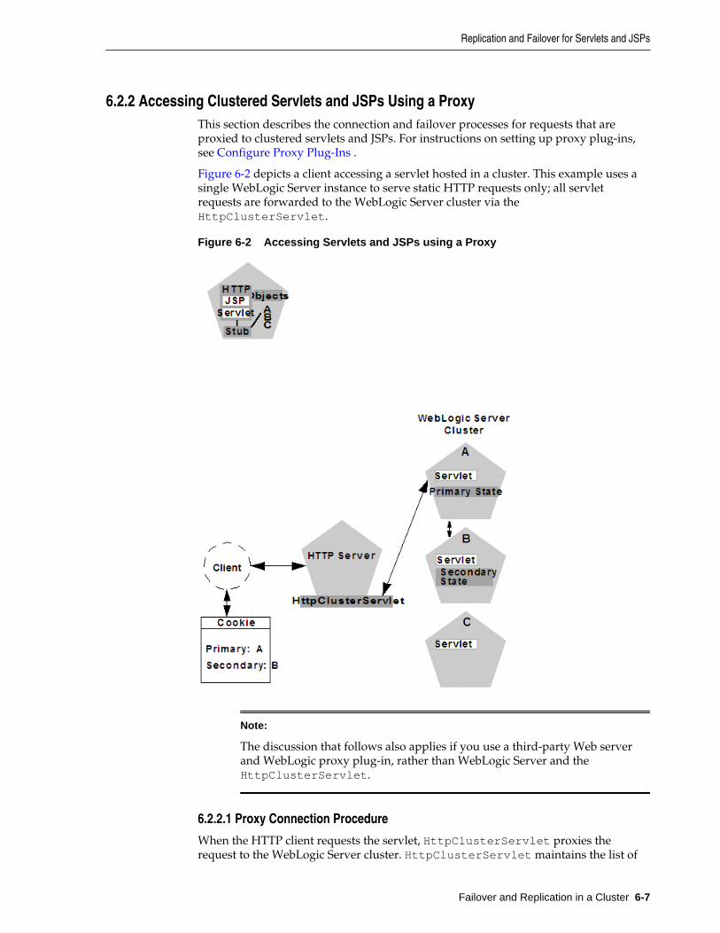
6.2.2 Accessing Clustered Servlets and JSPs Using a ProxyThis section describes the connection and failover processes for requests that areproxied to clustered servlets and JSPs. For instructions on setting up proxy plug-ins,see Configure Proxy Plug-Ins .
Figure 6-2 depicts a client accessing a servlet hosted in a cluster. This example uses asingle WebLogic Server instance to serve static HTTP requests only; all servletrequests are forwarded to the WebLogic Server cluster via theHttpClusterServlet.
Figure 6-2 Accessing Servlets and JSPs using a Proxy
Note:
The discussion that follows also applies if you use a third-party Web serverand WebLogic proxy plug-in, rather than WebLogic Server and theHttpClusterServlet.
6.2.2.1 Proxy Connection Procedure
When the HTTP client requests the servlet, HttpClusterServlet proxies therequest to the WebLogic Server cluster. HttpClusterServlet maintains the list of
Replication and Failover for Servlets and JSPs
Failover and Replication in a Cluster 6-7
all servers in the cluster, and the load balancing logic to use when accessing thecluster. In the above example, HttpClusterServlet routes the client request to theservlet hosted on WebLogic Server A. WebLogic Server A becomes the primary serverhosting the client's servlet session.
To provide failover services for the servlet, the primary server replicates the client'sservlet session state to a secondary WebLogic Server in the cluster. This ensures that areplica of the session state exists even if the primary server fails (for example, due to anetwork failure). In the example above, Server B is selected as the secondary.
The servlet page is returned to the client through the HttpClusterServlet, and theclient browser is instructed to write a cookie that lists the primary and secondarylocations of the servlet session state. If the client browser does not support cookies,WebLogic Server can use URL rewriting instead.
6.2.2.1.1 Using URL Rewriting to Track Session Replicas
In its default configuration, WebLogic Server uses client-side cookies to keep track ofthe primary and secondary server that host the client's servlet session state. If clientbrowsers have disabled cookie usage, WebLogic Server can also keep track of primaryand secondary servers using URL rewriting. With URL rewriting, both locations of theclient session state are embedded into the URLs passed between the client and proxyserver. To support this feature, you must ensure that URL rewriting is enabled on theWebLogic Server cluster. For instructions on how to enable URL rewriting, see UsingURL Rewriting Instead of Cookies in Developing Web Applications, Servlets, and JSPs forOracle WebLogic Server.
6.2.2.2 Proxy Failover Procedure
Should the primary server fail, HttpClusterServlet uses the client's cookieinformation to determine the location of the secondary WebLogic Server that hosts thereplica of the session state. HttpClusterServlet automatically redirects the client'snext HTTP request to the secondary server, and failover is transparent to the client.
After the failure, WebLogic Server B becomes the primary server hosting the servletsession state, and a new secondary is created (Server C in the previous example). Inthe HTTP response, the proxy updates the client's cookie to reflect the new primaryand secondary servers, to account for the possibility of subsequent failovers.
Note:
Now WebLogic proxy plug-ins randomly pick up a secondary server after thefailover.
In a two-server cluster, the client would transparently fail over to the server hostingthe secondary session state. However, replication of the client's session state would notcontinue unless another WebLogic Server became available and joined the cluster. Forexample, if the original primary server was restarted or reconnected to the network, itwould be used to host the secondary session state.
6.2.3 Accessing Clustered Servlets and JSPs with Load Balancing HardwareTo support direct client access via load balancing hardware, the WebLogic Serverreplication system allows clients to use secondary session states regardless of theserver to which the client fails over. WebLogic Server uses client-side cookies or URLrewriting to record primary and secondary server locations. However, thisinformation is used only as a history of the servlet session state location; when
Replication and Failover for Servlets and JSPs
6-8 Administering Clusters for Oracle WebLogic Server
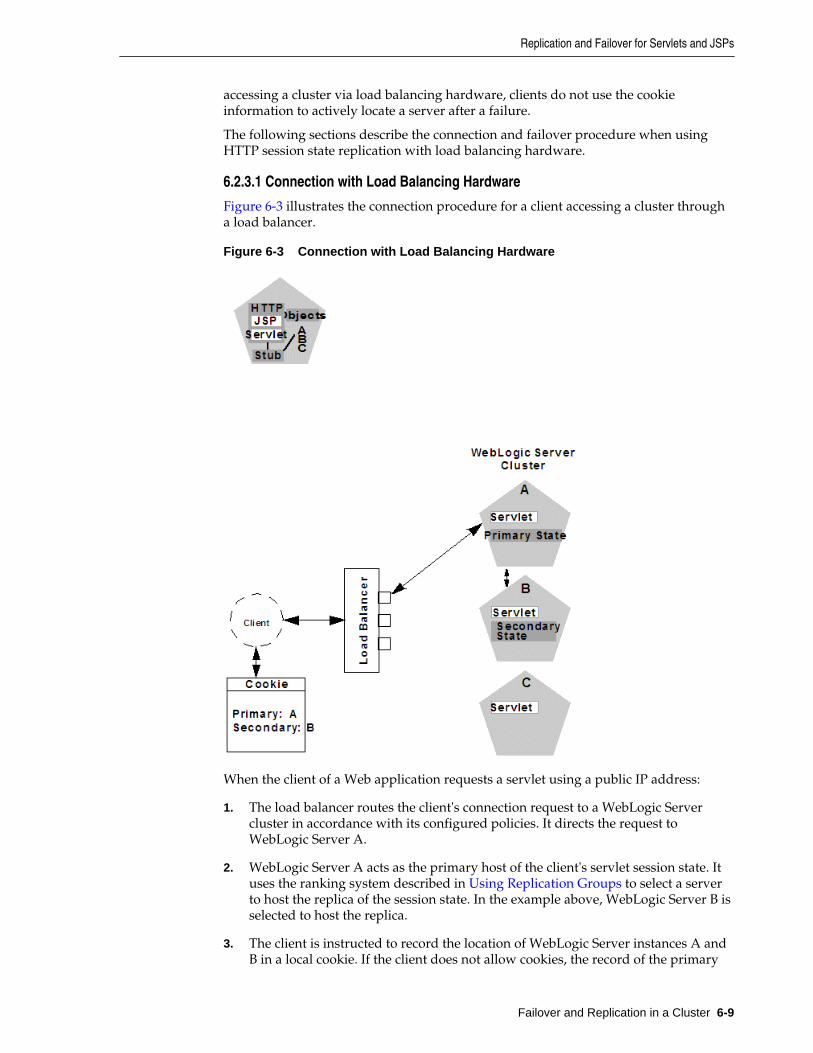
accessing a cluster via load balancing hardware, clients do not use the cookieinformation to actively locate a server after a failure.
The following sections describe the connection and failover procedure when usingHTTP session state replication with load balancing hardware.
6.2.3.1 Connection with Load Balancing Hardware
Figure 6-3 illustrates the connection procedure for a client accessing a cluster througha load balancer.
Figure 6-3 Connection with Load Balancing Hardware
When the client of a Web application requests a servlet using a public IP address:
1. The load balancer routes the client's connection request to a WebLogic Servercluster in accordance with its configured policies. It directs the request toWebLogic Server A.
2. WebLogic Server A acts as the primary host of the client's servlet session state. Ituses the ranking system described in Using Replication Groups to select a serverto host the replica of the session state. In the example above, WebLogic Server B isselected to host the replica.
3. The client is instructed to record the location of WebLogic Server instances A andB in a local cookie. If the client does not allow cookies, the record of the primary
Replication and Failover for Servlets and JSPs
Failover and Replication in a Cluster 6-9
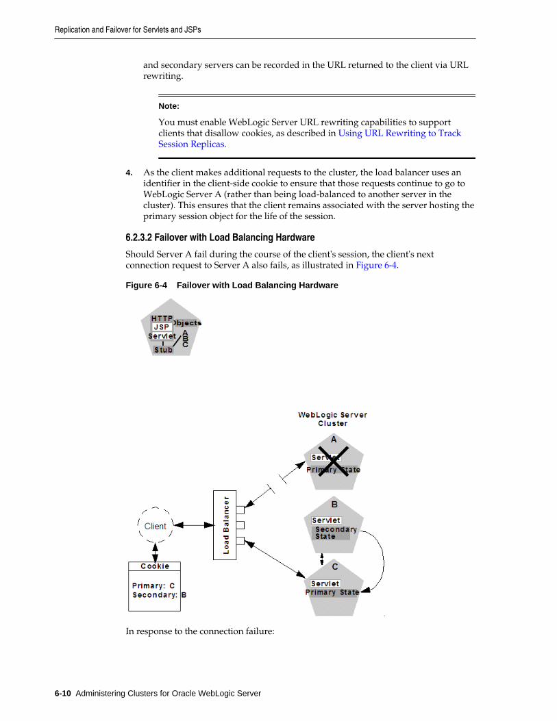
and secondary servers can be recorded in the URL returned to the client via URLrewriting.
Note:
You must enable WebLogic Server URL rewriting capabilities to supportclients that disallow cookies, as described in Using URL Rewriting to TrackSession Replicas.
4. As the client makes additional requests to the cluster, the load balancer uses anidentifier in the client-side cookie to ensure that those requests continue to go toWebLogic Server A (rather than being load-balanced to another server in thecluster). This ensures that the client remains associated with the server hosting theprimary session object for the life of the session.
6.2.3.2 Failover with Load Balancing Hardware
Should Server A fail during the course of the client's session, the client's nextconnection request to Server A also fails, as illustrated in Figure 6-4.
Figure 6-4 Failover with Load Balancing Hardware
In response to the connection failure:
Replication and Failover for Servlets and JSPs
6-10 Administering Clusters for Oracle WebLogic Server
1. The load balancing hardware uses its configured policies to direct the request toan available WebLogic Server in the cluster. In the above example, assume thatthe load balancer routes the client's request to WebLogic Server C after WebLogicServer A fails.
2. When the client connects to WebLogic Server C, the server uses the information inthe client's cookie (or the information in the HTTP request if URL rewriting isused) to acquire the session state replica on WebLogic Server B. The failoverprocess remains completely transparent to the client.
WebLogic Server C becomes the new host for the client's primary session state, andWebLogic Server B continues to host the session state replica. This new informationabout the primary and secondary host is again updated in the client's cookie, or viaURL rewriting.
6.2.4 Session State Replication Across Clusters in a MAN/WANIn addition to providing HTTP session state replication across servers within a cluster,WebLogic Server provides the ability to replicate HTTP session state across multipleclusters. This improves high-availability and fault tolerance by allowing clusters to bespread across multiple geographic regions, power grids, and Internet serviceproviders. This section discusses mechanisms for cross-cluster replication supportedby WebLogic Server:
• Network Requirements for Cross-cluster Replication
• Configuration Requirements for Cross-Cluster Replication
• MAN HTTP Session State Replication
• WAN HTTP Session State Replication
For general information on HTTP session state replication, see HTTP Session StateReplication. For more information on using hardware load balancers, see AccessingClustered Servlets and JSPs with Load Balancing Hardware.
6.2.4.1 Network Requirements for Cross-cluster Replication
To perform cross-cluster replication with WebLogic Server, your network mustinclude global and local hardware load balancers. Figure 6-5 shows how both types ofload balancers interact within a multi-cluster environment to support cross-clusterreplication. For general information on using load balancer within a WebLogic Serverenvironment, see Connection with Load Balancing Hardware.
Replication and Failover for Servlets and JSPs
Failover and Replication in a Cluster 6-11
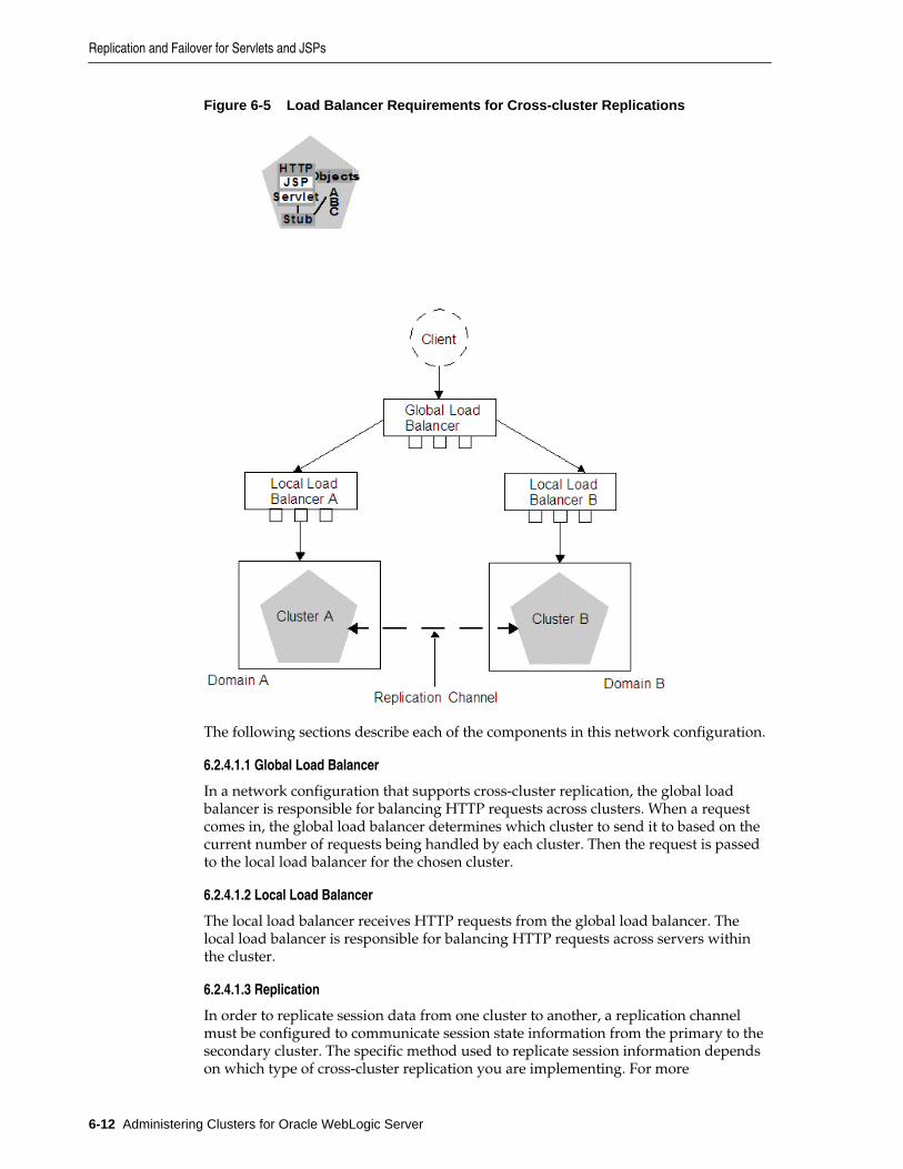
Figure 6-5 Load Balancer Requirements for Cross-cluster Replications
The following sections describe each of the components in this network configuration.
6.2.4.1.1 Global Load Balancer
In a network configuration that supports cross-cluster replication, the global loadbalancer is responsible for balancing HTTP requests across clusters. When a requestcomes in, the global load balancer determines which cluster to send it to based on thecurrent number of requests being handled by each cluster. Then the request is passedto the local load balancer for the chosen cluster.
6.2.4.1.2 Local Load Balancer
The local load balancer receives HTTP requests from the global load balancer. Thelocal load balancer is responsible for balancing HTTP requests across servers withinthe cluster.
6.2.4.1.3 Replication
In order to replicate session data from one cluster to another, a replication channelmust be configured to communicate session state information from the primary to thesecondary cluster. The specific method used to replicate session information dependson which type of cross-cluster replication you are implementing. For more
Replication and Failover for Servlets and JSPs
6-12 Administering Clusters for Oracle WebLogic Server
information, see MAN HTTP Session State Replication or WAN HTTP Session StateReplication.
6.2.4.1.4 Failover
When a server within a cluster fails, the local load balancer is responsible fortransferring the request to other servers within a cluster. When the entire cluster fails,the local load balancer returns HTTP requests back to the global load balancer. Theglobal load balancer then redirects this request to the other local load balancer.
6.2.4.2 Configuration Requirements for Cross-Cluster Replication
The following procedures outline the basic steps required to configure cross-clusterreplication.
1. Install WebLogic Server according to your network configuration andrequirements. This includes installing a WebLogic Server instance on everyphysical machine that hosts a WebLogic Server instance.
2. Install and configure the hardware load balancers. For more information on loadbalancer requirements see Network Requirements for Cross-cluster Replication.For more information on installing and configuring load balancers, see thedocumentation for your load balancer.
Following are some general considerations when configuring hardware loadbalancers to support cross-cluster replications:
• You must configure your load balancer to maintain session IDs. If the loadbalancers do not maintain session ID, subsequent requests will always be sent toa new server. For more information, see Connection with Load BalancingHardware.
• You should ensure that the cluster failover timeout value is not set to high. Thisvalue should be around 3-5 seconds. Some hardware load balancers havedefault values that are much longer.
• You must configure your load balancer to know which backup cluster to usewhen a primary cluster or server fails.
3. Create and configure your domains according to your cluster requirements.
Note:
Cross-cluster replication requires that each cluster be assigned to a differentdomain.
In addition to creating and configuring your domains, you should also create andconfigure your clusters and Managed Servers. For information about creating andconfiguring domains, clusters, and Managed Servers, see the following topics:
• Understanding Oracle WebLogic Server Domains in Understanding DomainConfiguration for Oracle WebLogic Server
• Clusters in Creating WebLogic Domains Using the Configuration Wizard
Following are some considerations when configuring domains to support cross-cluster replication:
Replication and Failover for Servlets and JSPs
Failover and Replication in a Cluster 6-13
• Each domain should be set up and configured identically. In addition toidentical domain, cluster and server configuration, the number of serversclusters, etc. should be identical.
• Application deployment should be identical in each domain.
• When setting up your domains, you must enable trust between both domains.For more information on enabling trust between domains, see Enabling TrustBetween WebLogic Server Domains in Administering Security for Oracle WebLogicServer
4. If you are using cross-cluster replication in a WAN environment, you must create adata source that is used to maintain session state. For more information, see Database Configuration for WAN Session State Replication.
5. After you have created and configured your domains, servers, and clusters youshould verify the configuration elements specific to cross-cluster replication havebeen configured correctly. These parameters must be configured identically forboth domains.
Table 6-2 lists the subelements of the cluster element in config.xml that are usedto configure cross-cluster replication:
Table 6-2 Cluster Elements in config.xml
Element Description
cluster-type This setting must match the replication type you areusing and must be consistent across both clusters.
The valid values are man or wan
remote-cluster-address This is the address used to communicate replicationinformation to the other cluster. This should beconfigured so that communications between clustersdo not go through a load balancer.
replication-channel This is the network channel used to communicatereplication information to the other cluster.
Note: The named channel must exist on all members ofthe cluster and must be configured to use the sameprotocol. The selected channel may be configured touse a secure protocol.
data-source-for-session-persistence This is the data source that is used to store sessioninformation when using JDBC-based sessionpersistence.
This method of session state replication is used toperform cross-cluster replication within a WAN. Formore information, see Database Configuration forWAN Session State Replication.
session-flush-interval This is the interval, in seconds, the cluster waits toflush HTTP sessions to the backup cluster.
Replication and Failover for Servlets and JSPs
6-14 Administering Clusters for Oracle WebLogic Server
Table 6-2 (Cont.) Cluster Elements in config.xml
Element Description
session-flush-threshold If the number of HTTP sessions reaches the value ofsession-flush-threshold, the sessions are flushed to thebackup cluster. This allows servers to flush sessionsfaster under heavy loads.
inter-cluster-comm-link-health-check-interval
This is the amount of time, in milliseconds, betweenconsecutive checks to determine if the link betweentwo clusters is restored.
6.2.4.3 Configuring Session State Replication Across Clusters
You can use a third-party replication product to replicate state across clusters, or youcan allow WebLogic Server to replicate session state across clusters. The followingconfiguration considerations should be kept in mind depending on which method youuse:
• If you are using a third-party product, ensure that you have specified a value forjdbc-pool, and that remote-cluster-address is blank.
• If you are using WebLogic Server to handle session state replication, you mustconfigure both the jdbc-pool and the remote-cluster-address.
If remote-cluster-address is NULL, WebLogic Server assumes that you areusing a third-party product to handle replication. In this case, session data is notpersisted to the remote database, but is persisted locally.
6.2.4.4 Configuring a Replication Channel
A replication channel is a normal network channel that is dedicated specifically toreplication traffic between clusters. For general information on configuring a networkchannel, see Configuring Network Resources in Administering Server Environments forOracle WebLogic Server.
When creating a network channel to be used as the replication channel in cross-clusterreplication, the following considerations apply:
• You must ensure that the replication channel is created on all cluster members andhas the same name.
• The channel should be used only for replication. Other types of network trafficshould be directed to other network channels.
6.2.4.5 MAN HTTP Session State Replication
Resources within a metropolitan area network (MAN) are often in physically separatelocations, but are geographically close enough that network latency is not an issue.Network communication in a MAN generally has low latency and fast interconnect.Clusters within a MAN can be installed in physically separate locations whichimproves availability.
To provide failover within a MAN, WebLogic Server provides an in-memorymechanism that works between two separate clusters. This allows session state to bereplicated synchronously from one cluster to another, provided that the network
Replication and Failover for Servlets and JSPs
Failover and Replication in a Cluster 6-15
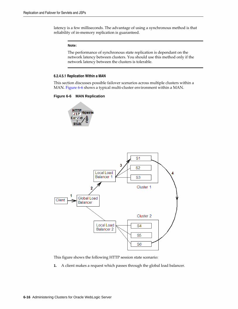
latency is a few milliseconds. The advantage of using a synchronous method is thatreliability of in-memory replication is guaranteed.
Note:
The performance of synchronous state replication is dependant on thenetwork latency between clusters. You should use this method only if thenetwork latency between the clusters is tolerable.
6.2.4.5.1 Replication Within a MAN
This section discusses possible failover scenarios across multiple clusters within aMAN. Figure 6-6 shows a typical multi-cluster environment within a MAN.
Figure 6-6 MAN Replication
This figure shows the following HTTP session state scenario:
1. A client makes a request which passes through the global load balancer.
Replication and Failover for Servlets and JSPs
6-16 Administering Clusters for Oracle WebLogic Server
2. The global load balancer passes the request to a local load balancer based oncurrent system load. In this case, the session request is passed to Local LoadBalancer 1.
3. The local load balancer in turn passes the request to a server within a clusterbased on system load, in this case S1. Once the request reaches S1, this ManagedServer becomes the primary server for this HTTP session. This server will handlesubsequent requests assuming there are no failures.
4. Session state information is stored in the database of the primary cluster.
5. After the server establishes the HTTP session, the current session state isreplicated to the designated secondary server.
6.2.4.5.2 Failover Scenarios in a MAN
The following sections describe various failover scenarios based on the MANconfiguration in Figure 6-6.
Failover Scenario 1
If all of the servers in Cluster 1 fail, the global load balancer will automatically fail allsubsequent session requests to Cluster 2. All sessions that have been replicated toCluster 2 will be recovered and the client will experience no data loss.
Failover Scenario 2
Assume that the primary server S1 is being hosted on Cluster 1, and the secondaryserver S6 is being hosted on Cluster 2. If S1 crashes, then any other server in Cluster 1(S2 or S3) can pick up the request and retrieve the session data from server S6. S6 willcontinue to be the backup server.
Failover Scenario 3
Assume that the primary server S1 is being hosted on Cluster 1, and the secondaryserver S6 is being hosted on Cluster 2. If the secondary server S6 fails, then theprimary server S1 will automatically select a new secondary server on Cluster 2. Uponreceiving a client request, the session information will be backed up on the newsecondary server.
Failover Scenario 4
If the communication between the two clusters fails, the primary server willautomatically replicate session state to a new secondary server within the local cluster.Once the communication between the two clusters, any subsequent client requests willbe replicated on the remote cluster.
6.2.4.5.3 MAN Replication, Load Balancers, and Session Stickiness
MAN replication relies on global load balancers to maintain cluster affinity and localload balancers to maintain server affinity. If a server within a cluster fails, the localload balancer is responsible for ensuring that session state is replicated to anotherserver in the cluster. If all of the servers within a cluster have failed or are unavailable,the global load balancer is responsible for replicating session state to another cluster.This ensures that failover to another cluster does not occur unless the entire clusterfails.
Once a client establishes a connection through a load balancer to a cluster, the clientmust maintain stickiness to that cluster as long as it is healthy.
Replication and Failover for Servlets and JSPs
Failover and Replication in a Cluster 6-17
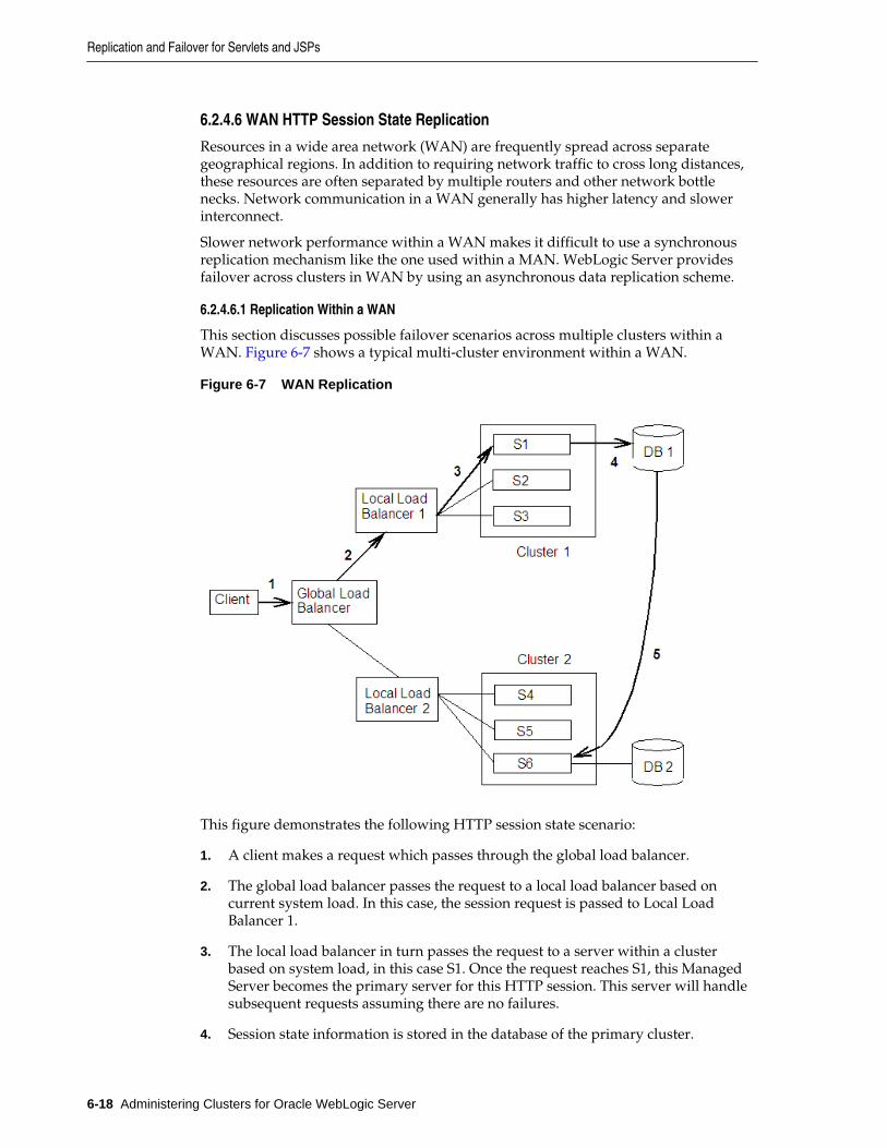
6.2.4.6 WAN HTTP Session State Replication
Resources in a wide area network (WAN) are frequently spread across separategeographical regions. In addition to requiring network traffic to cross long distances,these resources are often separated by multiple routers and other network bottlenecks. Network communication in a WAN generally has higher latency and slowerinterconnect.
Slower network performance within a WAN makes it difficult to use a synchronousreplication mechanism like the one used within a MAN. WebLogic Server providesfailover across clusters in WAN by using an asynchronous data replication scheme.
6.2.4.6.1 Replication Within a WAN
This section discusses possible failover scenarios across multiple clusters within aWAN. Figure 6-7 shows a typical multi-cluster environment within a WAN.
Figure 6-7 WAN Replication
This figure demonstrates the following HTTP session state scenario:
1. A client makes a request which passes through the global load balancer.
2. The global load balancer passes the request to a local load balancer based oncurrent system load. In this case, the session request is passed to Local LoadBalancer 1.
3. The local load balancer in turn passes the request to a server within a clusterbased on system load, in this case S1. Once the request reaches S1, this ManagedServer becomes the primary server for this HTTP session. This server will handlesubsequent requests assuming there are no failures.
4. Session state information is stored in the database of the primary cluster.
Replication and Failover for Servlets and JSPs
6-18 Administering Clusters for Oracle WebLogic Server
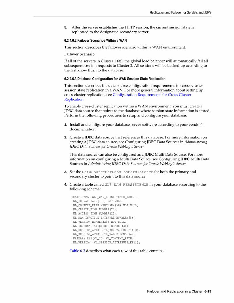
5. After the server establishes the HTTP session, the current session state isreplicated to the designated secondary server.
6.2.4.6.2 Failover Scenarios Within a WAN
This section describes the failover scenario within a WAN environment.
Failover Scenario
If all of the servers in Cluster 1 fail, the global load balancer will automatically fail allsubsequent session requests to Cluster 2. All sessions will be backed up according tothe last know flush to the database.
6.2.4.6.3 Database Configuration for WAN Session State Replication
This section describes the data source configuration requirements for cross-clustersession state replication in a WAN. For more general information about setting upcross-cluster replication, see Configuration Requirements for Cross-ClusterReplication.
To enable cross-cluster replication within a WAN environment, you must create aJDBC data source that points to the database where session state information is stored.Perform the following procedures to setup and configure your database:
1. Install and configure your database server software according to your vendor'sdocumentation.
2. Create a JDBC data source that references this database. For more information oncreating a JDBC data source, see Configuring JDBC Data Sources in AdministeringJDBC Data Sources for Oracle WebLogic Server
This data source can also be configured as a JDBC Multi Data Source. For moreinformation on configuring a Multi Data Source, see Configuring JDBC Multi DataSources in Administering JDBC Data Sources for Oracle WebLogic Server
3. Set the DataSourceForSessionPersistence for both the primary andsecondary cluster to point to this data source.
4. Create a table called WLS_WAN_PERSISTENCE in your database according to thefollowing schema:
CREATE TABLE WLS_WAN_PERSISTENCE_TABLE ( WL_ID VARCHAR2(100) NOT NULL, WL_CONTEXT_PATH VARCHAR2(50) NOT NULL, WL_CREATE_TIME NUMBER(20), WL_ACCESS_TIME NUMBER(20), WL_MAX_INACTIVE_INTERVAL NUMBER(38), WL_VERSION NUMBER(20) NOT NULL, WL_INTERNAL_ATTRIBUTE NUMBER(38), WL_SESSION_ATTRIBUTE_KEY VARCHAR2(100), WL_SESSION_ATTRIBUTE_VALUE LONG RAW, PRIMARY KEY(WL_ID, WL_CONTEXT_PATH, WL_VERSION, WL_SESSION_ATTRIBUTE_KEY));
Table 6-3 describes what each row of this table contains:
Replication and Failover for Servlets and JSPs
Failover and Replication in a Cluster 6-19
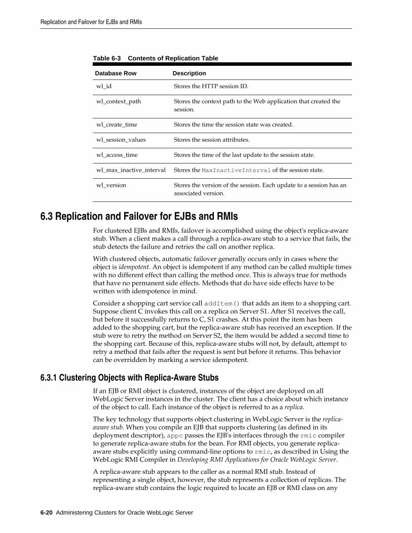
Table 6-3 Contents of Replication Table
Database Row Description
wl_id Stores the HTTP session ID.
wl_context_path Stores the context path to the Web application that created thesession.
wl_create_time Stores the time the session state was created.
wl_session_values Stores the session attributes.
wl_access_time Stores the time of the last update to the session state.
wl_max_inactive_interval Stores the MaxInactiveInterval of the session state.
wl_version Stores the version of the session. Each update to a session has anassociated version.
6.3 Replication and Failover for EJBs and RMIsFor clustered EJBs and RMIs, failover is accomplished using the object's replica-awarestub. When a client makes a call through a replica-aware stub to a service that fails, thestub detects the failure and retries the call on another replica.
With clustered objects, automatic failover generally occurs only in cases where theobject is idempotent. An object is idempotent if any method can be called multiple timeswith no different effect than calling the method once. This is always true for methodsthat have no permanent side effects. Methods that do have side effects have to bewritten with idempotence in mind.
Consider a shopping cart service call addItem() that adds an item to a shopping cart.Suppose client C invokes this call on a replica on Server S1. After S1 receives the call,but before it successfully returns to C, S1 crashes. At this point the item has beenadded to the shopping cart, but the replica-aware stub has received an exception. If thestub were to retry the method on Server S2, the item would be added a second time tothe shopping cart. Because of this, replica-aware stubs will not, by default, attempt toretry a method that fails after the request is sent but before it returns. This behaviorcan be overridden by marking a service idempotent.
6.3.1 Clustering Objects with Replica-Aware StubsIf an EJB or RMI object is clustered, instances of the object are deployed on allWebLogic Server instances in the cluster. The client has a choice about which instanceof the object to call. Each instance of the object is referred to as a replica.
The key technology that supports object clustering in WebLogic Server is the replica-aware stub. When you compile an EJB that supports clustering (as defined in itsdeployment descriptor), appc passes the EJB's interfaces through the rmic compilerto generate replica-aware stubs for the bean. For RMI objects, you generate replica-aware stubs explicitly using command-line options to rmic, as described in Using theWebLogic RMI Compiler in Developing RMI Applications for Oracle WebLogic Server.
A replica-aware stub appears to the caller as a normal RMI stub. Instead ofrepresenting a single object, however, the stub represents a collection of replicas. Thereplica-aware stub contains the logic required to locate an EJB or RMI class on any
Replication and Failover for EJBs and RMIs
6-20 Administering Clusters for Oracle WebLogic Server
WebLogic Server instance on which the object is deployed. When you deploy a cluster-aware EJB or RMI object, its implementation is bound into the JNDI tree. As describedin Cluster-Wide JNDI Naming Service, clustered WebLogic Server instances have thecapability to update the JNDI tree to list all server instances on which the object isavailable. When a client accesses a clustered object, the implementation is replaced bya replica-aware stub, which is sent to the client.
The stub contains the load balancing algorithm (or the call routing class) used to loadbalance method calls to the object. On each call, the stub can employ its load algorithmto choose which replica to call. This provides load balancing across the cluster in away that is transparent to the caller. To understand the load balancing algorithmsavailable for RMI objects and EJBs, see Load Balancing for EJBs and RMI Objects. If afailure occurs during the call, the stub intercepts the exception and retries the call onanother replica. This provides a failover that is also transparent to the caller.
6.3.2 Clustering Support for Different Types of EJBsEJBs differ from plain RMI objects in that each EJB can potentially generate twodifferent replica-aware stubs: one for the EJBHome interface and one for theEJBObject interface. This means that EJBs can potentially realize the benefits of loadbalancing and failover on two levels:
• When a client looks up an EJB object using the EJBHome stub
• When a client makes method calls against the EJB using the EJBObject stub
The following sections describe clustering support for different types of EJBs.
6.3.2.1 Clustered EJBHomes
All bean homes interfaces—used to find or create bean instances—can be clustered, byspecifying the home-is-clusterable element in weblogic-ejb-jar.xml.
Note:
Stateless session beans, stateful session beans, and entity beans have homeinterfaces. Message-driven beans do not.
When a bean is deployed to a cluster, each server binds the bean's home interface to itscluster JNDI tree under the same name. When a client requests the bean's home fromthe cluster, the server instance that does the look-up returns a EJBHome stub that has areference to the home on each server.
When the client issues a create() or find() call, the stub selects a server from thereplica list in accordance with the load balancing algorithm, and routes the call to thehome interface on that server. The selected home interface receives the call, andcreates a bean instance on that server instance and executes the call, creating aninstance of the bean.
Note:
WebLogic Server supports load balancing algorithms that provide serveraffinity for EJB home interfaces. To understand server affinity and how itaffects load balancing and failover, see Round-Robin Affinity_ Weight-BasedAffinity_ and Random-Affinity.
Replication and Failover for EJBs and RMIs
Failover and Replication in a Cluster 6-21
6.3.2.2 Clustered EJBObjects
An EJBObject stub tracks available replicas of an EJB in a cluster.
6.3.2.2.1 Stateless Session Beans
When a home creates a stateless bean, it returns a EJBObject stub that lists all of theservers in the cluster, to which the bean should be deployed. Because a stateless beanholds no state on behalf of the client, the stub is free to route any call to any server thathosts the bean. The stub can automatically fail over in the event of a failure. The stubdoes not automatically treat the bean as idempotent, so it will not recoverautomatically from all failures. If the bean has been written with idempotent methods,this can be noted in the deployment descriptor and automatic failover will be enabledin all cases.
Note:
WebLogic Server supports load balancing options that provide server affinityfor stateless EJB remote interfaces. To understand server affinity and how itaffects load balancing and failover, see Round-Robin Affinity_ Weight-BasedAffinity_ and Random-Affinity.
6.3.2.2.2 Stateful Session Beans
Method-level failover for a stateful service requires state replication. WebLogic Serversatisfies this requirement by replicating the state of the primary bean instance to asecondary server instance, using a replication scheme similar to that used for HTTPsession state.
When a home interface creates a stateless session bean instance, it selects a secondaryinstance to host the replicated state, using the same rules defined in Using ReplicationGroups. The home interface returns a EJBObject stub to the client that lists thelocation of the primary bean instance, and the location for the replicated bean state.
Figure 6-8 shows a client accessing a clustered stateful session EJB.
Replication and Failover for EJBs and RMIs
6-22 Administering Clusters for Oracle WebLogic Server
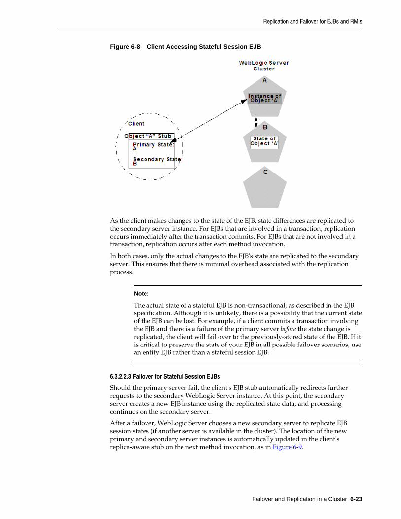
Figure 6-8 Client Accessing Stateful Session EJB
As the client makes changes to the state of the EJB, state differences are replicated tothe secondary server instance. For EJBs that are involved in a transaction, replicationoccurs immediately after the transaction commits. For EJBs that are not involved in atransaction, replication occurs after each method invocation.
In both cases, only the actual changes to the EJB's state are replicated to the secondaryserver. This ensures that there is minimal overhead associated with the replicationprocess.
Note:
The actual state of a stateful EJB is non-transactional, as described in the EJBspecification. Although it is unlikely, there is a possibility that the current stateof the EJB can be lost. For example, if a client commits a transaction involvingthe EJB and there is a failure of the primary server before the state change isreplicated, the client will fail over to the previously-stored state of the EJB. If itis critical to preserve the state of your EJB in all possible failover scenarios, usean entity EJB rather than a stateful session EJB.
6.3.2.2.3 Failover for Stateful Session EJBs
Should the primary server fail, the client's EJB stub automatically redirects furtherrequests to the secondary WebLogic Server instance. At this point, the secondaryserver creates a new EJB instance using the replicated state data, and processingcontinues on the secondary server.
After a failover, WebLogic Server chooses a new secondary server to replicate EJBsession states (if another server is available in the cluster). The location of the newprimary and secondary server instances is automatically updated in the client'sreplica-aware stub on the next method invocation, as in Figure 6-9.
Replication and Failover for EJBs and RMIs
Failover and Replication in a Cluster 6-23
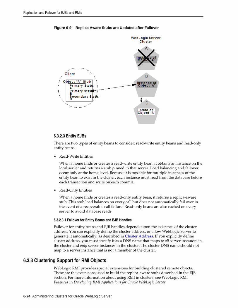
Figure 6-9 Replica Aware Stubs are Updated after Failover
6.3.2.3 Entity EJBs
There are two types of entity beans to consider: read-write entity beans and read-onlyentity beans.
• Read-Write Entities
When a home finds or creates a read-write entity bean, it obtains an instance on thelocal server and returns a stub pinned to that server. Load balancing and failoveroccur only at the home level. Because it is possible for multiple instances of theentity bean to exist in the cluster, each instance must read from the database beforeeach transaction and write on each commit.
• Read-Only Entities
When a home finds or creates a read-only entity bean, it returns a replica-awarestub. This stub load balances on every call but does not automatically fail over inthe event of a recoverable call failure. Read-only beans are also cached on everyserver to avoid database reads.
6.3.2.3.1 Failover for Entity Beans and EJB Handles
Failover for entity beans and EJB handles depends upon the existence of the clusteraddress. You can explicitly define the cluster address, or allow WebLogic Server togenerate it automatically, as described in Cluster Address. If you explicitly definecluster address, you must specify it as a DNS name that maps to all server instances inthe cluster and only server instances in the cluster. The cluster DNS name should notmap to a server instance that is not a member of the cluster.
6.3.3 Clustering Support for RMI ObjectsWebLogic RMI provides special extensions for building clustered remote objects.These are the extensions used to build the replica-aware stubs described in the EJBsection. For more information about using RMI in clusters, see WebLogic RMIFeatures in Developing RMI Applications for Oracle WebLogic Server.
Replication and Failover for EJBs and RMIs
6-24 Administering Clusters for Oracle WebLogic Server
6.3.4 Object Deployment RequirementsIf you are programming EJBs to be used in a WebLogic Server cluster, read theinstructions in this section to understand the capabilities of different EJB types in acluster. Then ensure that you enable clustering in the EJB's deployment descriptor. See weblogic-ejb-jar.xml Deployment Descriptor Reference in Developing EnterpriseJavaBeans, Version 2.1, for Oracle WebLogic Server for information about the XMLdeployment elements relevant for clustering.
If you are developing either EJBs or custom RMI objects, also refer to Using WebLogicJNDI in a Clustered Environment in Developing JNDI Applications for Oracle WebLogicServer to understand the implications of binding clustered objects in the JNDI tree.
6.3.4.1 Other Failover Exceptions
Even if a clustered object is not idempotent, WebLogic Server performs automaticfailover in the case of a ConnectException or MarshalException. Either of theseexceptions indicates that the object could not have been modified, and therefore thereis no danger of causing data inconsistency by failing over to another instance.
Replication and Failover for EJBs and RMIs
Failover and Replication in a Cluster 6-25

Replication and Failover for EJBs and RMIs
6-26 Administering Clusters for Oracle WebLogic Server
7Whole Server Migration
This chapter describes the different migration mechanisms supported by WebLogicServer.
This chapter includes the following sections:
• Understanding Server and Service Migration
• Migration Terminology
• Leasing
• Automatic Whole Server Migration
• Whole Server Migration with Dynamic and Mixed Clusters
These sections focus on whole server-level migration, where a migratable serverinstance, and all of its services, is migrated to a different physical machine uponfailure. WebLogic Server also supports service-level migration, as well as replicationand failover at the application level. For more information, see Service Migration and Failover and Replication in a Cluster.
7.1 Understanding Server and Service MigrationIn a WebLogic Server cluster, most services are deployed homogeneously on all serverinstances in the cluster, enabling transparent failover from one server instance toanother. In contrast, "pinned services" such as JMS and the JTA transaction recoverysystem are targeted at individual server instances within a cluster—for these services,WebLogic Server supports failure recovery with migration, as opposed to failover.
Migration in WebLogic Server is the process of moving a clustered WebLogic Serverinstance or a component running on a clustered server instance elsewhere in the eventof failure. In the case of whole server migration, the server instance is migrated to adifferent physical machine upon failure. In the case of service-level migration, theservices are moved to a different server instance within the cluster. See ServiceMigration.
To make JMS and the JTA transaction system highly available, WebLogic Serverprovides migratable servers. Migratable servers provide for both automatic and manualmigration at the server-level, rather than the service-level.
When a migratable server becomes unavailable for any reason—for example, if ithangs, loses network connectivity, or its host machine fails—migration is automatic.Upon failure, a migratable server is automatically restarted on the same machine, ifpossible. If the migratable server cannot be restarted on the machine where it failed, itis migrated to another machine. In addition, an administrator can manually initiatemigration of a server instance.
Whole Server Migration 7-1
7.2 Migration TerminologyThe following terms apply to server and service migration:
• Migratable server—a clustered server instance that migrates in its entirety, alongwith all the services it hosts. Migratable servers are intended to host pinnedservices, such as JMS servers and JTA transaction recovery servers, but migratableservers can also host clusterable services. All services that run on a migratableserver are highly available.
• Whole server migration— a WebLogic Server instance to be migrated to a differentphysical machine upon failure, either manually or automatically.
• Service migration:
– Manual Service Migration—the manual migration of pinned JTA and JMS-related services (for example, JMS server, SAF agent, path service, and customstore) after the host server instance fails. See Service Migration.
– Automatic Service Migration—JMS-related services, singleton services, and theJTA Transaction Recovery Service can be configured to automatically migrate toanother member server instance when a member server instance fails or isrestarted. See Service Migration.
• Cluster leader—one server instance in a cluster, elected by a majority of the serverinstances, that is responsible for maintaining the leasing information. See Non-database Consensus Leasing.
• Cluster master—one server instance in a cluster that contains migratable serversacts as the cluster master and orchestrates the process of automatic server migrationin the event of failure. Any Managed Server in a cluster can serve as the clustermaster, whether it hosts pinned services or not. See Cluster Master Role in WholeServer Migration.
• Singleton master—a lightweight singleton service that monitors other services thatcan be migrated automatically. The server instance that currently hosts thesingleton master is responsible for starting and stopping the migration tasksassociated with each migratable service. See Singleton Master.
• Candidate machines—a user-defined list of machines within a cluster that can be apotential target for migration.
• Target machines—a set of machines that are designated as allowable or preferredhosts for migratable servers.
• Node Manager—a WebLogic Server utility used by the Administration Server or astandalone Node Manager client, to start and stop migratable servers. NodeManager is invoked by the cluster master to shut down and restart migratableservers, as necessary. For background information about Node Manager and how itfits into a WebLogic Server environment, see Node Manager Overview inAdministering Node Manager for Oracle WebLogic Server.
• Lease table—a database table in which migratable servers persist their state, andwhich the cluster master monitors to verify the health and liveness of migratableservers. For more information on leasing, see Leasing.
Migration Terminology
7-2 Administering Clusters for Oracle WebLogic Server
• Administration Server—used to configure migratable servers and target machines,to obtain the run-time state of migratable servers, and to orchestrate the manualmigration process.
• Floating IP address—an IP address that follows a server instance from one physicalmachine to another after migration.
7.3 LeasingLeasing is the process WebLogic Server uses to manage services that are required torun on only one member of a cluster at a time. Leasing ensures exclusive ownership ofa cluster-wide entity. Within a cluster, there is a single owner of a lease. Additionally,leases can failover in case of server or cluster failure. This helps to avoid having asingle point of failure.
7.3.1 Features That Use LeasingThe following WebLogic Server features use leasing:
• Automatic Whole Server Migration—Uses leasing to elect a cluster master. Thecluster master is responsible for monitoring other cluster members and forrestarting failed members hosted on other physical machines.
Leasing ensures that the cluster master is always running, but is only running onone server instance at a time within a cluster. For information on the cluster master,see Cluster Master Role in Whole Server Migration.
• Automatic Service Migration—JMS-related services, singleton services, and the JTATransaction Recovery Service can be configured to automatically migrate from anunhealthy hosting server instance to a healthy active server instance with the helpof the health monitoring subsystem. When the migratable target is migrated, thepinned service hosted by that target is also migrated. Migratable targets use leasingto accomplish automatic service migration. See Service Migration.
• Singleton Services—A singleton service is a service running within a cluster that isavailable on only one member of the cluster at a time. Singleton services use leasingto accomplish this. See Singleton Master.
• Job Scheduler—The Job Scheduler is a persistent timer that is used within a cluster.The Job Scheduler uses the timer master to load balance the timer across a cluster.
This feature requires an external database to maintain failover and replicationinformation. However, you can use the non-database version, consensus leasing,with the Job Scheduler,
Note:
Beyond basic configuration, most leasing functionality is handled internallyby WebLogic Server.
7.3.2 Types of LeasingWebLogic Server provides two types of leasing functionality, depending on yourrequirements and your environment.
Leasing
Whole Server Migration 7-3

• High-availability database leasing—This version of leasing requires a high-availability database to store leasing information. For information on generalrequirements and configuration, see High-availability Database Leasing.
• Non-database consensus leasing—This version of leasing stores the leasinginformation in-memory within a cluster member. This version of leasing requiresthat all server instances in the cluster are started by Node Manager. For moreinformation, see Non-database Consensus Leasing.
Within a WebLogic Server installation, you can use only one type of leasing. Althoughit is possible to implement multiple features that use leasing within your environment,each must use the same kind of leasing.
When switching from one leasing type to another, you must restart the entire cluster,not just the Administration Server. Changing the leasing type cannot be donedynamically.
7.3.3 Determining Which Type of Leasing To UseThe following considerations will help you determine which type of leasing isappropriate for your WebLogic Server environment:
• High-availability database leasing
Database leasing basis is useful in environments that are already invested in ahigh-availability database, like Oracle RAC, for features like JMS store recovery.The high-availability database instance can also be configured to support leasingwith minimal additional configuration. This is particularly useful if Node Manageris not running in the system.
• Non-database consensus leasing
This type of leasing provides a leasing basis option (consensus) that does notrequire the use of a high-availability database. This has a direct benefit in automaticwhole server migration. Without the high-availability database requirement,consensus leasing requires less configuration to enable automatic server migration.
Consensus leasing requires Node Manager to be configured and running.Automatic whole server migration also requires Node Manager for IP migrationand server restart on another machine. Hence, consensus leasing works well sinceit does not impose additional requirements, but instead takes away an expensiveone.
7.3.4 High-availability Database LeasingIn this version of leasing, lease information is maintained within a table in a high-availability database. A high-availability database is required to ensure that theleasing information is always available to the server instances. Each member of thecluster must be able to connect to the database in order to access leasing information,update, and renew their leases. server instances will fail if the database becomesunavailable and they are not able to renew their leases.
This method of leasing is useful for customers who already have a high-availabilitydatabase within their clustered environment. This method allows you to use leasingfunctionality without requiring Node Manager to manage server instances withinyour environment.
The following procedures outline the steps required to configure your database forleasing.
Leasing
7-4 Administering Clusters for Oracle WebLogic Server
1. Configure the database for server migration. The database stores leasinginformation that is used to determine whether or not a server instance is running orneeds to be migrated.
Your database must be reliable. The server instances will only be as reliable as thedatabase. For experimental purposes, a regular database will suffice. For aproduction environment, only high-availability databases are recommended. If thedatabase goes down, all the migratable servers will shut themselves down.
Create the leasing table in the database. This is used to store the machine-serverassociations used to enable server migration. The schema for this table is located inWL_HOME/server/db/dbname/leasing.ddl, where dbname is the name of thedatabase vendor.
Note:
The leasing table should be stored in a highly available database. Migratableservers are only as reliable as the database used to store the leasing table.
2. Set up and configure a data source. This data source should point to the databaseconfigured in the previous step.
Note:
XA data sources are not supported for server migration.
For more information on creating a JDBC data source, see Configuring JDBC DataSources in Administering JDBC Data Sources for Oracle WebLogic Server.
7.3.4.1 Server Migration with Database Leasing on RAC Clusters
When using server migration with database leasing on RAC Clusters, Oraclerecommends synchronizing all RAC nodes in the environment. If the nodes are notsynchronized, it is possible that a Managed Server that is renewing a lease willevaluate that the value of the clock on the RAC node is greater than the timeout valueof leasing table. If it is more than 30 seconds, the server instance will fail and restartwith the following log message:
<Mar 29, 2013 2:39:09 PM EDT> <Error> <Cluster> <BEA-000150> <Server failedto get a connection to the database in the past 60 seconds for lease renewal.Server will shut itself down.>
See "Configuring Time Synchronization for the Cluster" in the Oracle Grid InfrastructureInstallation Guide.
Leasing
Whole Server Migration 7-5
7.3.5 Non-database Consensus Leasing
Note:
Consensus leasing requires that you use Node Manager to control serverinstances within the cluster. Node Manager must be running on everymachine hosting Managed Servers within the cluster, including any candidatemachines for failed migratable servers. For more information, see Using NodeManager to Control Servers in Administering Node Manager for Oracle WebLogicServer.
In Consensus leasing, there is no highly available database required. The cluster leadermaintains the leases in-memory. All of the server instances renew their leases bycontacting the cluster leader, however, the leasing table is replicated to other nodes ofthe cluster to provide failover.
The cluster leader is elected by all of the running server instances in the cluster. Aserver instance becomes a cluster leader only when it has received acceptance from themajority of the server instances. If Node Manager reports a server instance as shutdown, the cluster leader assumes that server instance has accepted it as leader whencounting the majority number of server instances.
Consensus leasing requires a majority of server instances to continue functioning. Anytime there is a network partition, the server instances in the majority partition willcontinue to run while those in the minority partition will voluntarily shut down sincethey cannot contact the cluster leader or elect a new cluster leader since they will nothave the majority of server instances. If the partition results in an equal division ofserver instances, then the partition that contains the cluster leader will survive whilethe other one will fail. Consensus leasing depends on the ability to contact NodeManager to receive the status of the server instances it is managing in order to countthem as part of the majority of reachable server instances. If Node Manager cannot becontacted, due to loss of network connectivity or a hardware failure, the serverinstances it manages are not counted as part of the majority, even if they are running.
Note:
If your cluster only contains two server instances, the cluster leader will be themajority partition if a network partition occurs. If the cluster leader fails, thesurviving server instance will attempt to verify its status through NodeManager. If the surviving server instance is able to determine the status of thefailed cluster leader, it assumes the role of cluster leader. If the survivingserver instance cannot check the status of the cluster leader, due to machinefailure or a network partition, it will voluntarily shut down as it cannotreliably determine if it is in the majority.
To avoid this scenario, Oracle recommends using a minimum of three serverinstances running on different machines.
If automatic server migration is enabled, server instances are required to contact thecluster leader and renew their leases periodically. Server instances will shutthemselves down if they are unable to renew their leases. The failed server instanceswill then be automatically migrated to the machines in the majority partition.
Leasing
7-6 Administering Clusters for Oracle WebLogic Server
7.4 Automatic Whole Server MigrationThis section outlines the procedures for configuring automatic whole server migrationand provides a general discussion of how whole server migration functions within aWebLogic Server environment.
The following topics are covered:
• Preparing for Automatic Whole Server Migration
• Configuring Automatic Whole Server Migration
• Using High Availability Storage for State Data
• Server Migration Processes and Communications
7.4.1 Preparing for Automatic Whole Server MigrationBefore configuring automatic whole server migration, be aware of the followingrequirements:
• Verify that whole server migration is supported on your platform. See Support forServer Migration in Oracle WebLogic Server, WebLogic Portal and WebLogic Integration10gR3 (10.3).
Note:
Support for automatic whole server migration on Solaris 10 systems using theSolaris Zones feature can be found in Note 3: Support For Sun Solaris 10 InMulti-Zone Operation at http://www.oracle.com/technetwork/middleware/ias/oracleas-supported-virtualization-089265.html.
• Each Managed Server uses the same subnet mask. Unicast and multicastcommunication among server instances requires each server instance to use thesame subnet. Server migration will not work without configuring multicast orunicast communication.
For information on using multicast, see Using IP Multicast. For information onusing unicast, see One-to-Many Communication Using Unicast.
• All server instances hosting migratable servers are time-synchronized. Althoughmigration works when server instances are not time-synchronized, time-synchronized server instances are recommended in a clustered environment.
• If you are using different operating system versions among migratable servers,ensure that all versions support identical functionality for ifconfig.
• Automatic whole server migration requires Node Manager to be configured andrunning for IP migration and server restart on another machine.
• The primary interface names used by migratable servers are the same. If yourenvironment requires different interface names, then configure a local version ofwlscontrol.sh for each migratable server.
For more information on wlscontrol.sh, see Using Node Manager to ControlServers in Administering Node Manager for Oracle WebLogic Server.
Automatic Whole Server Migration
Whole Server Migration 7-7
• See Databases Supporting WebLogic Server Features in Oracle WebLogic Server,WebLogic Portal and WebLogic Integration 10gR3 (10.3) for a list of databases forwhich WebLogic Server supports automatic server migration.
• There is no built-in mechanism for transferring files that a server instance dependson between machines. Using a disk that is accessible from all machines is thepreferred way to ensure file availability. If you cannot share disks between serverinstances, you must ensure that the contents of domain_dir/bin are copied toeach machine.
• Ensure that the Node Manager security files are copied to each machine using thenmEnroll() WLST command. For more information, see Using Node Manager toControl Servers in Administering Node Manager for Oracle WebLogic Server.
• Use high availability storage for state data. For highest reliability, use a sharedstorage solution that is itself highly available—for example, a storage area network(SAN). See Using High Availability Storage for State Data.
• For capacity planning in a production environment, keep in mind that serverstartup during migration taxes CPU utilization. You cannot assume that because amachine can handle a certain number of server instances running concurrently thatit also can handle that same number of server instances starting up on the samemachine at the same time.
7.4.2 Configuring Automatic Whole Server MigrationBefore configuring server migration, ensure that your environment meets therequirements outlined in Preparing for Automatic Whole Server Migration.
To configure server migration for a Managed Server within a cluster, perform thefollowing tasks:
1. Obtain floating IP addresses for each Managed Server that will have migrationenabled.
Each migratable server must be assigned a floating IP address which follows theserver instance from one physical machine to another after migration. Any serverinstance that is assigned a floating IP address must also haveAutoMigrationEnabled set to true.
Note:
The migratable IP address should not be present on the interface of any of thecandidate machines before the migratable server is started.
2. Configure Node Manager. Node Manager must be running and configured toallow server migration.
The Java version of Node Manager can be used for server migration on Windowsor UNIX. The script-based version of Node Manager can be used for servermigration on UNIX only.
When using Java-based Node Manager, you must editnodemanager.properties to add your environment Interface and NetMaskvalues.
To determine the most appropriate Interface value for your environment, usethe operating system utility to find the list of network interfaces available on the
Automatic Whole Server Migration
7-8 Administering Clusters for Oracle WebLogic Server
machine. On Unix platforms, this is typically the ifconfig command. OnWindows platforms, this is typically the ipconfig command.
To determine NetMask, you can use the same NetMask value that may already beconfigured for addresses on that same interface to ensure that all traffic occurs onthe same subnet. You can also specify a common NetMask value, and thereforespecify a subnet for all WebLogic Server traffic.
The nodemanager.properties file is located in the directory specified inNodeManagerHome, typically ORACLE_HOME\user_projects\domains\domain_name\nodemanager or ORACLE_HOME\oracle_common\common\nodemanager. For information about nodemanager.properties, see Reviewing nodemanager.properties in Administering Node Manager for OracleWebLogic Server.
If you are using the script-based version of Node Manager, edit wlscontrol.shand set the Interface variable to the name of your network interface.
For general information on using Node Manager in server migration, see NodeManager Role in Whole Server Migration. For general information about NodeManager, see Node Manager Overview in Administering Node Manager for OracleWebLogic Server.
3. If you are using a database to manage leasing information, configure the databasefor server migration according to the procedures outlined in High-availabilityDatabase Leasing. For general information on leasing, see Leasing.
4. If you are using database leasing within a test environment and you need to resetthe leasing table, you should re-run the leasing.ddl script. This causes thecorrect tables to be dropped and re-created.
5. If you are using a database to store leasing information, set up and configure a datasource according to the procedures outlined in High-availability Database Leasing.
You should set DataSourceForAutomaticMigration to this data source ineach cluster configuration.
Note:
XA data sources are not supported for server migration.
For more information on creating a JDBC data source, see Configuring JDBC DataSources in Administering JDBC Data Sources for Oracle WebLogic Server.
6. Grant superuser privileges to the wlsifconfig.sh script (on UNIX) or thewlsifconfig.cmd script (on Windows).
This script is used to transfer IP addresses from one machine to another duringmigration. It must be able to run ifconfig, which is generally only available tosuperusers. You can edit the script so that it is invoked using sudo.
Java-based Node Manager uses the wlsifconfig.cmd script, which uses thenetsh utility.
The wlsifconfig scripts are available in the WL_HOME/common/bin orDOMAIN_HOME/bin/server_migration directory.
7. Ensure that the following commands are included in your machine PATH:
Automatic Whole Server Migration
Whole Server Migration 7-9
• wlsifconfig.sh (UNIX) or wlsifconfig.cmd (Windows)
• wlscontrol.sh (UNIX)
• nodemanager.domains
The wlsifconfig.sh, wlsifconfig.cmd, and wlscontrol.sh files arelocated in WL_HOME/common/bin or DOMAIN_HOME/bin/server_migration.The nodemanager.domains file is located in the directory specified inNodeManagerHome. For Java-based Node Manager, NodeManagerHome istypically located in ORACLE_HOME\user_projects\domains\domain_name\nodemanager or ORACLE_HOME\oracle_common\common\nodemanager.For script-based Node Manager, this file's default NodeManagerHome location isWL_HOME/common/nodemanager, where WL_HOME is the location in which youinstalled WebLogic Server, for example, ORACLE_HOME/wlserver.
Depending on your default shell on UNIX, you may need to edit the first line ofthe .sh scripts.
8. This step applies only to the script-based version of Node Manager and UNIX. Ifyou are using Windows, skip to step 9.
The machines that host migratable servers must trust each other. For servermigration to occur, it must be possible to get to a shell prompt using 'ssh/rshmachine_A' from machine_B and vice versa without having to explicitly enter ausername and password. Also, each machine must be able to connect to itself usingSSH in the same way.
Note:
You should ensure that your login scripts (.cshrc, .profile, .login, andsuch) only echo messages from your shell profile if the shell is interactive.WebLogic Server uses an ssh command to login and echo the contents of theserver.state file. Only the first line of this output is used to determine theserver state.
9. Set the candidate machines for server migration. Each server instance can have adifferent set of candidate machines, or they can all have the same set.
10. Restart the Administration Server.
7.4.3 Using High Availability Storage for State DataThe server migration process migrates services, but not the state informationassociated with work in process at the time of failure.
To ensure high availability, it is critical that such state information remains availableto the server instance and the services it hosts after migration. Otherwise, data aboutthe work in process at the time of failure may be lost. State information maintained bya migratable server, such as the data contained in transaction logs, should be stored ina shared storage system that is accessible to any potential machine to which a failedmigratable server might be migrated. For highest reliability, use a shared storagesolution that is itself highly available—for example, a storage area network (SAN).
In addition, if you are using a database to store leasing information, the lease table,described in the following sections, should also be stored in a high availabilitydatabase. The lease table tracks the health and liveness of migratable servers. For moreinformation, see Leasing.
Automatic Whole Server Migration
7-10 Administering Clusters for Oracle WebLogic Server
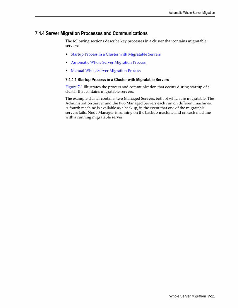
7.4.4 Server Migration Processes and CommunicationsThe following sections describe key processes in a cluster that contains migratableservers:
• Startup Process in a Cluster with Migratable Servers
• Automatic Whole Server Migration Process
• Manual Whole Server Migration Process
7.4.4.1 Startup Process in a Cluster with Migratable Servers
Figure 7-1 illustrates the process and communication that occurs during startup of acluster that contains migratable servers.
The example cluster contains two Managed Servers, both of which are migratable. TheAdministration Server and the two Managed Servers each run on different machines.A fourth machine is available as a backup, in the event that one of the migratableservers fails. Node Manager is running on the backup machine and on each machinewith a running migratable server.
Automatic Whole Server Migration
Whole Server Migration 7-11
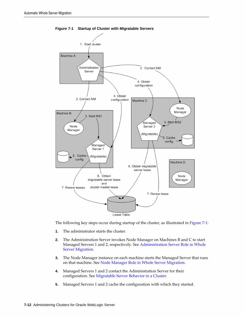
Figure 7-1 Startup of Cluster with Migratable Servers
The following key steps occur during startup of the cluster, as illustrated in Figure 7-1:
1. The administrator starts the cluster.
2. The Administration Server invokes Node Manager on Machines B and C to startManaged Servers 1 and 2, respectively. See Administration Server Role in WholeServer Migration.
3. The Node Manager instance on each machine starts the Managed Server that runson that machine. See Node Manager Role in Whole Server Migration.
4. Managed Servers 1 and 2 contact the Administration Server for theirconfiguration. See Migratable Server Behavior in a Cluster.
5. Managed Servers 1 and 2 cache the configuration with which they started.
Automatic Whole Server Migration
7-12 Administering Clusters for Oracle WebLogic Server
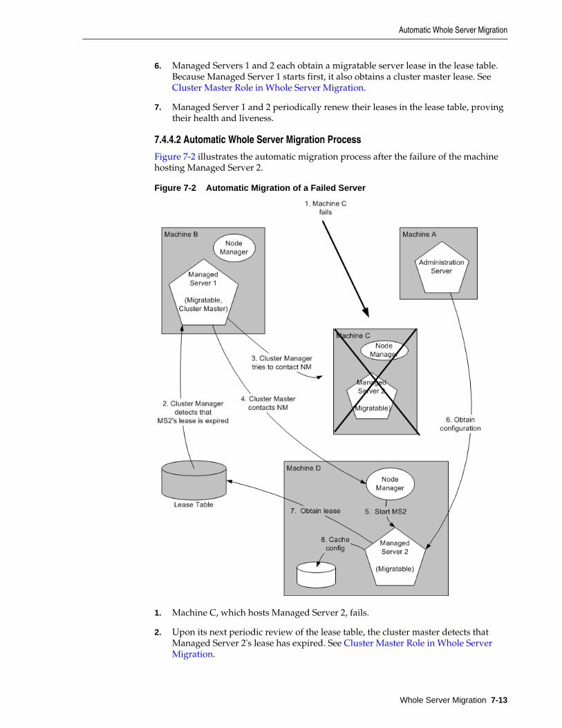
6. Managed Servers 1 and 2 each obtain a migratable server lease in the lease table.Because Managed Server 1 starts first, it also obtains a cluster master lease. See Cluster Master Role in Whole Server Migration.
7. Managed Server 1 and 2 periodically renew their leases in the lease table, provingtheir health and liveness.
7.4.4.2 Automatic Whole Server Migration Process
Figure 7-2 illustrates the automatic migration process after the failure of the machinehosting Managed Server 2.
Figure 7-2 Automatic Migration of a Failed Server
1. Machine C, which hosts Managed Server 2, fails.
2. Upon its next periodic review of the lease table, the cluster master detects thatManaged Server 2's lease has expired. See Cluster Master Role in Whole ServerMigration.
Automatic Whole Server Migration
Whole Server Migration 7-13
3. The cluster master tries to contact Node Manager on Machine C to restartManaged Server 2, but fails because Machine C is unreachable.
Note:
If the Managed Server 2 lease had expired because it was hung, and MachineC was reachable, the cluster master would use Node Manager to restartManaged Server 2 on Machine C.
4. The cluster master contacts Node Manager on Machine D, which is configured asan available host for migratable servers in the cluster.
5. Node Manager on Machine D starts Managed Server 2. See Node Manager Role inWhole Server Migration.
6. Managed Server 2 starts and contacts the Administration Server to obtain itsconfiguration.
7. Managed Server 2 caches the configuration with which it started.
8. Managed Server 2 obtains a migratable server lease.
During migration, the clients of the Managed Server that is migrating may experiencea brief interruption in service; it may be necessary to reconnect. On Solaris and Linuxoperating systems, this can be done using the ifconfig command. The clients of amigrated server do not need to know the particular machine to which they havemigrated.
When a machine that previously hosted a server instance that was migrated becomesavailable again, the reversal of the migration process—migrating the server instanceback to its original host machine—is known as failback. WebLogic Server does notautomate the failback process. An administrator can accomplish failback by manuallyrestoring the server instance to its original host.
The general procedures for restoring a server instance to its original host are asfollows:
• Gracefully shut down the new instance of the server.
• After you have restarted the failed machine, restart Node Manager and theManaged Server.
The exact procedures you will follow depend on your server instance and networkenvironment.
7.4.4.3 Manual Whole Server Migration Process
Figure 7-3 illustrates what happens when an administrator manually migrates amigratable server.
Automatic Whole Server Migration
7-14 Administering Clusters for Oracle WebLogic Server
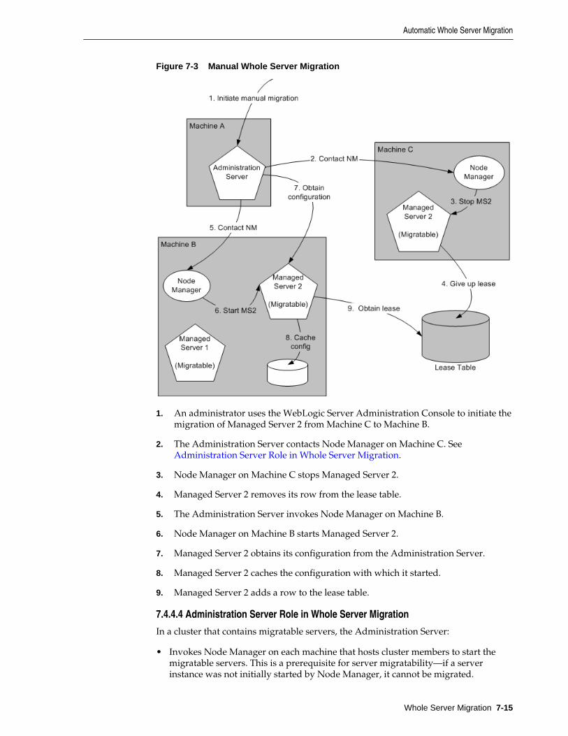
Figure 7-3 Manual Whole Server Migration
1. An administrator uses the WebLogic Server Administration Console to initiate themigration of Managed Server 2 from Machine C to Machine B.
2. The Administration Server contacts Node Manager on Machine C. See Administration Server Role in Whole Server Migration.
3. Node Manager on Machine C stops Managed Server 2.
4. Managed Server 2 removes its row from the lease table.
5. The Administration Server invokes Node Manager on Machine B.
6. Node Manager on Machine B starts Managed Server 2.
7. Managed Server 2 obtains its configuration from the Administration Server.
8. Managed Server 2 caches the configuration with which it started.
9. Managed Server 2 adds a row to the lease table.
7.4.4.4 Administration Server Role in Whole Server Migration
In a cluster that contains migratable servers, the Administration Server:
• Invokes Node Manager on each machine that hosts cluster members to start themigratable servers. This is a prerequisite for server migratability—if a serverinstance was not initially started by Node Manager, it cannot be migrated.
Automatic Whole Server Migration
Whole Server Migration 7-15
• Invokes Node Manager on each machine involved in a manual migration processto stop and start the migratable server.
• Invokes Node Manager on each machine that hosts cluster members to stop serverinstances during a normal shutdown. This is a prerequisite for server migratability—if a server instance is shut down directly, without using Node Manager, whenthe cluster master detects that the server instance is not running, it will call NodeManager to restart it.
In addition, the Administration Server provides its regular domain managementfunctionality, persisting configuration updates issued by an administrator, andproviding a run-time view of the domain, including the migratable servers it contains.
7.4.4.5 Migratable Server Behavior in a Cluster
A migratable server is a clustered Managed Server that has been configured asmigratable. A migratable server has the following key behaviors:
• If you are using a database to manage leasing information, during startup andrestart by Node Manager, a migratable server adds a row to the lease table. Therow for a migratable server contains a timestamp and the machine where it isrunning.
For more information about leasing, see Leasing.
• When using a database to manage leasing information, a migratable server adds arow to the database as a result of startup. It tries to take on the role of clustermaster and succeeds if it is the first server instance to join the cluster.
• Periodically, the server renews its lease by updating the timestamp in the leasetable.
By default, a migratable server renews its lease every 30,000 milliseconds—theproduct of two configurable ServerMBean properties:
– HealthCheckIntervalMillis, which by default is 10,000.
– HealthCheckPeriodsUntilFencing, which by default is 3.
• If a migratable server fails to reach the lease table and renew its lease before thelease expires, it terminates as quickly as possible using a Java System.exit—inthis case, the lease table still contains a row for that server instance. For informationabout how this relates to automatic migration, see Cluster Master Role in WholeServer Migration.
• During operation, a migratable server listens for heartbeats from the cluster master.When it detects that the cluster master is not sending heartbeats, it attempts to takeover the role of cluster master and succeeds if no other server instance has claimedthat role.
Note:
During server migration, keep in mind that server startup taxes CPUutilization. You cannot assume that because a machine can support a certainnumber of server instances running concurrently that they also can supportthat same number of server instances starting up on the same machine at thesame time.
Automatic Whole Server Migration
7-16 Administering Clusters for Oracle WebLogic Server
7.4.4.6 Node Manager Role in Whole Server Migration
The use of Node Manager is required for server migration—it must run on eachmachine that hosts or is intended to host.
Node Manager supports server migration in the following ways:
• Node Manager must be used for initial startup of migratable servers.
When you initiate the startup of a Managed Server from the WebLogic ServerAdministration Console, the Administration Server uses Node Manager to start theserver instance. You can also invoke Node Manager to start the server instanceusing the standalone Node Manager client; however, the Administration Servermust be available so that the Managed Server can obtain its configuration.
Note:
Migration of a server instance that is not initially started with Node Managerwill fail.
• Node Manager must be used to suspend, shut down, or force shut downmigratable servers.
• Node Manager tries to restart a migratable server whose lease has expired on themachine where it was running at the time of failure.
Node Manager performs the steps in the server migration process by runningcustomizable shell scripts that are provided with WebLogic Server. These scriptscan start, restart and stop server instances, migrate IP addresses, and mount andunmount disks. The scripts are available for Solaris and Linux.
– In an automatic migration, the cluster master invokes Node Manager to performthe migration.
– In a manual migration, the Administration Server invokes Node Manager toperform the migration.
7.4.4.7 Cluster Master Role in Whole Server Migration
In a cluster that contains migratable servers, one server instance acts as the clustermaster. Its role is to orchestrate the server migration process. Any server instance inthe cluster can serve as the cluster master. When you start a cluster that containsmigratable servers, the first server instance to join the cluster becomes the clustermaster and starts the cluster manager service. If a cluster does not include at least onemigratable server, it does not require a cluster master, and the cluster manager servicedoes not start. In the absence of a cluster master, migratable servers can continue tooperate, but server migration is not possible. The cluster master serves the followingkey functions:
• Issues periodic heartbeats to the other server instances in the cluster.
• Periodically reads the lease table to verify that each migratable server has a currentlease. An expired lease indicates to the cluster master that the migratable servershould be restarted.
• Upon determining that a migratable server's lease is expired, the cluster masterwaits for a period specified by the FencingGracePeriodMillis on the
Automatic Whole Server Migration
Whole Server Migration 7-17
ClusterMBean and then tries to invoke the Node Manager process on themachine that hosts the migratable server whose lease is expired, in order to restartthe migratable server.
• If unable to restart a migratable server whose lease has expired on its currentmachine, the cluster master selects a target machine in the following fashion:
– If you have configured a list of preferred destination machines for themigratable server, the cluster master chooses a machine on that list, in the orderthe machines are listed.
– Otherwise, the cluster master chooses a machine on the list of those configuredas available for hosting migratable servers in the cluster.
A list of machines that can host migratable servers can be configured at twolevels: for the cluster as a whole and for an individual migratable server. Youcan define a machine list at both levels. You must define a machine list on atleast one level.
• To accomplish the migration of a server instance to a new machine, the clustermaster invokes the Node Manager process on the target machine to create aprocess for the server instance.
The time required to perform the migration depends on the server configurationand startup time.
– The maximum time taken for the cluster master to restart the migratable serveris (HealthCheckPeriodsUntilFencing * HealthCheckIntervalMillis)+ FencingGracePeriodMillis.
– The total time before the server instance becomes available for client requestsdepends on the server startup time and the application deployment time.
7.5 Whole Server Migration with Dynamic and Mixed ClustersWebLogic Server supports whole server migration with dynamic and mixed clusters.When a dynamic server in a dynamic cluster fails, the server instance is migrated to adifferent physical machine upon failure the same way as a configured server in aconfigured or mixed cluster. While configuration differs depending on the clustertype, whole server migration behavior is the same for all clusters. For moreinformation about dynamic and mixed clusters, see Dynamic Clusters.
Automatic whole server migration uses leasing to elect a cluster master, which isresponsible for monitoring other cluster members and for restarting failed membershosted on other physical machines. You configure leasing in the cluster configuration.For more information, see Leasing.
7.5.1 Configuring Whole Server Migration with Dynamic ClustersWhen configuring automatic whole server migration for configured clusters, youselect the individual server instances you want to be able to migrate. You also choose asubset of available machines to which you want to migrate server instances uponfailure.
For a dynamic cluster, you enable or disable automatic whole server migration in theserver template. A dynamic cluster uses a single server template to define itsconfiguration, and all dynamic server instances within the dynamic cluster inherit thetemplate configuration. If you enable automatic whole server migration in the server
Whole Server Migration with Dynamic and Mixed Clusters
7-18 Administering Clusters for Oracle WebLogic Server
template for a dynamic cluster, all dynamic server instances based on that servertemplate are then enabled for automatic whole server migration. You cannot selectindividual dynamic server instances to migrate.
Additionally, you cannot choose the machines to which you want to migrate. Afterenabling automatic whole server migration in the server template for a dynamiccluster, all machines that are available to use for migration are automatically selected.
You cannot limit the list of candidate machines for migration that the dynamic clusterspecifies, as the server template does not list candidate machines. The list of candidatemachines for each dynamic server is calculated as follows:
ClusterMBean.CandidateMachinesForMigratableServers = { M1, M2, M3 } dyn-server-1.CandidateMachines = { M1, M2, M3}dyn-server-2.CandidateMachines = { M2, M3, M1 }dyn-server-3.CandidateMachines = { M3, M1, M2 }dyn-server-4.CandidateMachines = { M1, M2, M3 }
To enable automatic whole server migration for a dynamic cluster using the WebLogicServer Administration Console:
1. In the left pane of the WebLogic Server Administration Console, selectEnvironment > Clusters > Server Templates.
2. In the Server Templates table, select the server template for your dynamic cluster.
3. Select Configuration > Migration.
4. Select the Automatic Server Migration Enabled attribute.
7.5.2 Configuring Whole Server Migration with Mixed ClustersA mixed cluster contains both dynamic and configured servers. To enable automaticwhole server migration for a mixed cluster:
1. Enable automatic whole server migration in the server template used by thedynamic server instances in the mixed cluster.
All of the dynamic server instances based on that server template are then enabledfor automatic whole server migration.
2. Manually enable automatic whole server migration for any of the configured serverinstances in the cluster and choose the machines to which you want to migrate if aserver instance fails.
Whole Server Migration with Dynamic and Mixed Clusters
Whole Server Migration 7-19

Whole Server Migration with Dynamic and Mixed Clusters
7-20 Administering Clusters for Oracle WebLogic Server
8Service Migration
This chapter describes the service migration mechanisms supported by WebLogicServer.
This chapter includes the following sections:
• Understanding the Service Migration Framework
• Pre-Migration Requirements
• Roadmap for Configuring AutomaticMigration of JMS-related Services
• Best Practices for Targeting JMS when Configuring Automatic Service Migration
• Roadmap for Configuring Manual Migration of JMS-related Services
• Roadmap for Configuring Automatic Migration of the JTA Transaction RecoveryService
• Manual Migration of the JTA Transaction Recovery Service
• Automatic Migration of User-Defined Singleton Services
This chapter focuses on migrating failed services. WebLogic Server also supportswhole server-level migration, where a migratable server instance, and all of itsservices, is migrated to a different physical machine upon failure. For information onfailed server migration, see Whole Server Migration.
WebLogic Server also supports replication and failover at the application level. Formore information, see Failover and Replication in a Cluster.
Note:
Support for automatic whole server migration on Solaris 10 systems using theSolaris Zones feature can be found in Note 3: Support For Sun Solaris 10 InMulti-Zone Operation at http://www.oracle.com/technetwork/middleware/ias/oracleas-supported-virtualization-089265.html.
8.1 Understanding the Service Migration FrameworkIn a WebLogic Server cluster, most subsystem services are hosted homogeneously onall server instances in the cluster, enabling transparent failover from one server toanother. In contrast, pinned services, such as JMS-related services, the JTA TransactionRecovery Service, and user-defined singleton services are hosted on individual serverinstances within a cluster—for these services, the WebLogic Server migration
Service Migration 8-1
framework supports failure recovery with service migration, as opposed to failover. See Migratable Services.
Service-level migration in WebLogic Server is the process of moving the pinnedservices from one server instance to a different available server instance within thecluster. Service migration is controlled by a logical migratable target, which serves as agrouping of services that is hosted on only one physical server instance in a cluster.You can select a migratable target in place of a server instance or cluster whentargeting certain pinned services. High availability is achieved by migrating amigratable target from one clustered server instance to another when a problem occurson the original server instance. You can also manually migrate a migratable target forscheduled maintenance, or you can configure the migratable target for automaticmigration. See Understanding Migratable Targets In a Cluster.
The migration framework provides tools and infrastructure for configuring andmigrating targets, and, in the case of automatic service migration, it leverages theWebLogic Server health monitoring subsystem to monitor the health of serviceshosted by a migratable target. See Migration Processing Tools and Automatic ServiceMigration Infrastructure. For definitions of the terms that apply to server and servicemigration, see Migration Terminology.
8.1.1 Migratable ServicesWebLogic Server supports service-level migration for JMS-related services, the JTATransaction Recovery Service, and user-defined singleton services. These are referredto as migratable services because you can move them from one server instance toanother within a cluster. The following migratable services can be configured forautomatic or manual migration.
8.1.1.1 JMS-related Services
These are the migratable JMS services:
• JMS Server—management containers for the queues and topics in JMS modulesthat are targeted to them. See JMS Server Configuration in Administering JMSResources for Oracle WebLogic Server.
• Store-and-Forward (SAF) Service—store-and-forward messages between localsending and remote receiving endpoints, even when the remote endpoint is notavailable at the moment the messages are sent. Only sending SAF agentsconfigured for JMS SAF (sending capability only) are migratable. See Administeringthe Store-and-Forward Service for Oracle WebLogic Server.
• Path Service—a persistent map that can be used to store the mapping of a group ofmessages in a JMS Message Unit-of-Order to a messaging resource in a cluster. Itprovides a way to enforce ordering by pinning messages to a member of a clusterhosting servlets, distributed queue members, or Store-and-Forward agents. Onepath service is configured per cluster. See Using the WebLogic Path Service inAdministering JMS Resources for Oracle WebLogic Server.
• Custom Persistent Store—a user-defined, disk-based file store or JDBC-accessibledatabase for storing subsystem data, such as persistent JMS messages or store-and-forward messages. See Administering the WebLogic Persistent Store.
Cluster targeted JMS services are distributed over the members of the clusters.Weblogic Server can be configured to automatically migrate cluster targeted servicesacross cluster members dynamically. See Simplified JMS Cluster and High AvailabilityConfiguration in Administering JMS Resources for Oracle WebLogic Server.
Understanding the Service Migration Framework
8-2 Administering Clusters for Oracle WebLogic Server
To ensure that singleton JMS services do not introduce a single point of failure fordependent applications in the cluster, WebLogic Server can be configured toautomatically or manually migrate them to any server instance in the migratable targetlist. See Roadmap for Configuring Automatic Migration of JMS-related Services and Roadmap for Configuring Manual Migration of JMS-related Services.
8.1.1.2 JTA Transaction Recovery Service
The Transaction Recovery Service automatically attempts to recover transactions onsystem startup by parsing all transaction log records for incomplete transactions andcompleting them. For detailed information, see Transaction Recovery After a ServerFails in Developing JTA Applications for Oracle WebLogic Server.
8.1.1.3 User-defined Singleton Services
Within an application, you can define a singleton service that can be used to performtasks that you want to be executed on only one member of a cluster at any give time.See Automatic Migration of User-Defined Singleton Services.
8.1.2 Understanding Migratable Targets In a Cluster
Note:
When dynamic cluster is configured, you can specify the migration policy atthe custom persistent store level and that determines the migration behaviorof JMS services. For more information, see Simplified JMS Cluster and HighAvailability Configuration in Administering JMS Resources for Oracle WebLogicServer.
You can also configure JMS and JTA services for high availability by using migratabletargets. A migratable target is a special target that can migrate from one serverinstance in a cluster to another. As such, a migratable target provides a way to groupmigratable services that should move together. When the migratable target ismigrated, all services hosted by that target are migrated.
A migratable target specifies a set of server instances that can host a target, and canoptionally specify a user-preferred host for the services and an ordered list ofcandidate backup servers should the preferred server instance fail. Only one of theseserver instances can host the migratable target at any one time.
Once a service is configured to use a migratable target, then the service is independentfrom the server member that is currently hosting it. For example, if a JMS server with adeployed JMS queue is configured to use a migratable target, then the queue isindependent of when a specific server member is available. In other words, the queueis always available when the migratable target is hosted by any server instance in thecluster.
An administrator can manually migrate pinned migratable services from one serverinstance to another in the cluster, either in response to a server failure or as part ofregularly scheduled maintenance. If you do not configure a migratable target in thecluster, migratable services can be migrated to any WebLogic Server instance in thecluster. See Roadmap for Configuring Manual Migration of JMS-related Services.
Understanding the Service Migration Framework
Service Migration 8-3
8.1.2.1 Policies for Manual and Automatic Service Migration
A migratable target provides migration policies that define whether the hostedservices will be manually migrated (the system default) or automatically migratedfrom an unhealthy hosting server instance to a healthy active server instance with thehelp of the health monitoring subsystem. There are two types of automatic servicemigration policies, as described in the following sections.
8.1.2.1.1 Manual Migration
When a migratable target uses the manual policy (the system default), anadministrator can manually migrate pinned migratable services from one serverinstance to another in the cluster, either in response to a server failure or as part ofregularly scheduled maintenance.
See Roadmap for Configuring Manual Migration of JMS-related Services.
8.1.2.1.2 Exactly-Once
This policy indicates that if at least one Managed Server in the candidate list isrunning, then the service will be active somewhere in the cluster if server instances failor are shut down (either gracefully or forcibly). It is important to note that this valuecan lead to target grouping. For example, if you have five exactly-once migratabletargets and only start one Managed Server in the cluster, then all five targets will beactivated on that server instance.
Note:
As a best practice, a migratable target hosting a path service should always beset to exactly-once, so if its hosting server member fails or is shut down,the path service will automatically migrate to another server instance and willalways be active in the cluster.
Example use-case for JMS servers:
A domain has a cluster of three Managed Servers, with one JMS server deployed on amember server in the cluster. Applications deployed to the cluster send messages tothe queues targeted to the JMS server. MDBs in another domain drain the queuesassociated with the JMS server. The MDBs only want to drain from one set of queues,not from many instances of the same queue. In other words, this environment usesclustering for scalability, load balancing, and failover for its applications, but not for itsJMS server. Therefore, this environment would benefit from the automatic migrationof the JMS server as an exactly-once service to an available cluster member.
See Roadmap for Configuring Automatic Migration of JMS-related Services.
8.1.2.1.3 Failure-Recovery
This policy indicates that the service will only start if its user-preferred server (UPS) isstarted. If an administrator manually shuts down the UPS, either gracefully orforcibly, then a failure-recovery service will not migrate. However, if the UPSfails due to an internal error, then a failure-recovery service will be migrated toanother candidate server instance. If such a candidate server instance is unavailable(due to a manual shutdown or an internal failure), then the migration framework willfirst attempt to reactivate the service on its UPS server. If the UPS server is notavailable at that time, then the service will be migrated to another candidate serverinstance.
Understanding the Service Migration Framework
8-4 Administering Clusters for Oracle WebLogic Server
For migration of cluster targeted JMS services, you can configure a Store with failurerecovery parameters.
Example use-case for JMS servers:
A domain has a cluster of three Managed Servers, with a JMS server on each memberserver and a distributed queue member on each JMS server. There is also an MDBtargeted to the cluster that drains from the distributed queue member on the localserver member. In other words, this environment uses clustering for overallscalability, load balancing, and failover. Therefore, this environment would benefitfrom the automatic migration of a JMS server as an failure-recovery service to aUPS member.
Note:
If a server instance is also configured to use the automatic whole servermigration framework, which will shut down the server when its expired leasecannot be renewed, then any failure-recovery services configured on thatserver instance will not automatically migrate, no matter how the serverinstance is manually shut down by an administrator (for example, forceshutdown versus graceful shutdown). For more information, see AutomaticWhole Server Migration.
See the Roadmap for Configuring Automatic Migration of JMS-related Services.
8.1.2.2 Options For Attempting to Restart Failed Services Before Migrating
A migratable target provides options to attempt to deactivate and reactivate a failedservice, instead of migrating the service. See In-Place Restarting of Failed MigratableServices.
For more information about the default values for all migratable target options, see MigratableTargetMBean in the MBean Reference for Oracle WebLogic Server.
8.1.2.3 User-Preferred Servers and Candidate Servers
When deploying a JMS service to the migratable target, you can select the user-preferred server (UPS) target to host the service. When configuring a migratabletarget, you can also specify constrained candidate servers (CCS) that can potentiallyhost the service should the user-preferred server fail. If the migratable target does notspecify a constrained candidate server, the JMS server can be migrated to any availableserver instance in the cluster.
WebLogic Server enables you to create separate migratable targets for JMS services.This allows you to always keep each service running on a different server instance inthe cluster, if necessary. Conversely, you can configure the same selection of serverinstances as the constrained candidate servers for both JTA and JMS, to ensure that theservices remain co-located on the same server instance in the cluster.
8.1.2.4 Example Migratable Targets In a Cluster
Figure 8-1 shows a cluster of three Managed Servers, all hosting migratable targets.Server A is hosting a migratable target (MT1) for JMS server A (with two queues) anda custom store; Server B is hosting MT2 for a path service and a custom store and isalso hosting MT3 for JMS server B (with two queues) and a custom store; Server C ishosting MT4 for JMS server C (with two queues) and a custom store.
Understanding the Service Migration Framework
Service Migration 8-5
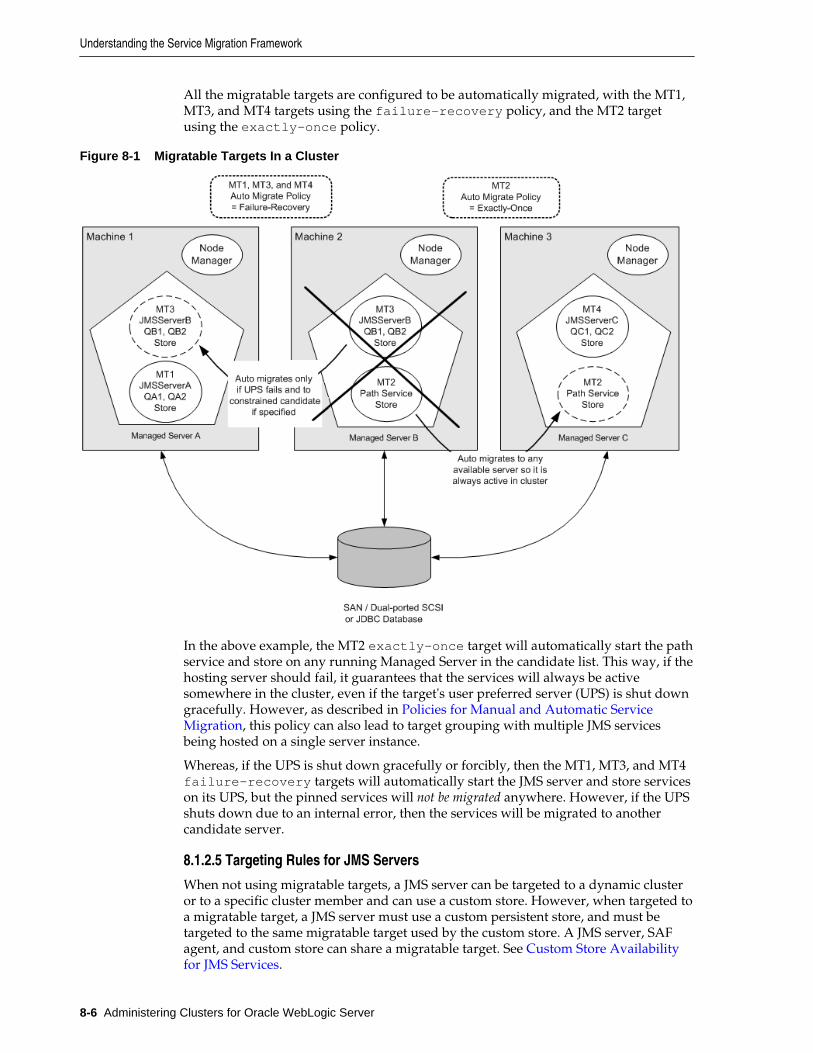
All the migratable targets are configured to be automatically migrated, with the MT1,MT3, and MT4 targets using the failure-recovery policy, and the MT2 targetusing the exactly-once policy.
Figure 8-1 Migratable Targets In a Cluster
In the above example, the MT2 exactly-once target will automatically start the pathservice and store on any running Managed Server in the candidate list. This way, if thehosting server should fail, it guarantees that the services will always be activesomewhere in the cluster, even if the target's user preferred server (UPS) is shut downgracefully. However, as described in Policies for Manual and Automatic ServiceMigration, this policy can also lead to target grouping with multiple JMS servicesbeing hosted on a single server instance.
Whereas, if the UPS is shut down gracefully or forcibly, then the MT1, MT3, and MT4failure-recovery targets will automatically start the JMS server and store serviceson its UPS, but the pinned services will not be migrated anywhere. However, if the UPSshuts down due to an internal error, then the services will be migrated to anothercandidate server.
8.1.2.5 Targeting Rules for JMS Servers
When not using migratable targets, a JMS server can be targeted to a dynamic clusteror to a specific cluster member and can use a custom store. However, when targeted toa migratable target, a JMS server must use a custom persistent store, and must betargeted to the same migratable target used by the custom store. A JMS server, SAFagent, and custom store can share a migratable target. See Custom Store Availabilityfor JMS Services.
Understanding the Service Migration Framework
8-6 Administering Clusters for Oracle WebLogic Server
WebLogic Server will create the migratable targets for each server instance in a clusterand then create separate JMS servers that are targeted individually to each migratabletarget, if a JMS system resource target is the cluster.
8.1.2.6 Targeting Rules for SAF Agents
When not using migratable targets, a SAF agent can be targeted to an entire cluster ora list of multiple server instances in a cluster, with the requirement that the SAF agentand each server instance in the cluster must use the default persistent store. However,when targeted to a migratable target, a SAF agent must use a custom persistent store,and must be targeted to the same migratable target used by the custom store, similarto a JMS server. A SAF agent, JMS server, and custom store can share a migratabletarget. See Special Considerations When Targeting SAF Agents or Path Service.
WebLogic Server will create the migratable targets for each server in a cluster and thencreate separate SAF agents that are targeted individually to each migratable target.This handling increases throughput and high availability.
In addition, consider the following topics when targeting SAF agents to migratabletargets.
8.1.2.6.1 Re-targeting SAF Agents to Migratable Targets
To preserve SAF message consistency, WebLogic Server prevents you from retargetingan existing SAF agent to a migratable target. Instead, you must delete the existing SAFagent and configure a new SAF agent with the same values and target it to amigratable target.
8.1.2.6.2 Targeting Migratable SAF Agents For Increased Message Throughput
When not using migratable targets, a SAF agent can be targeted to an entire cluster ormultiple server instances in a cluster for increased message throughput. However,When a SAF agent is targeted to a migratable target, it cannot be targeted to any otherserver instances in the cluster, including an entire cluster. Therefore, if you want toincrease throughput by importing a JMS destination to multiple SAF agents onseparate server instances in a cluster, then you should create migratable targets foreach server instance in the cluster and then create separate SAF agents that aretargeted individually to each migratable target.
8.1.2.6.3 Targeting SAF Agents For Consistent Quality-of-Service
A WebLogic Server administrator has the freedom to configure and deploy multipleSAF agents in the same cluster or on the same server instance. As such, there could besituations where the same server instance has both migratable SAF agents and non-migratable SAF agents. For such cases, the behavior of a JMS client application mayvary depending on which SAF agent handles the messages.
For example, an imported destination can be deployed to multiple SAF agents, andmessages sent to the imported destination will be load-balanced among all SAFagents. If the list of the SAF agents contains non-migratable agents, the JMS clientapplication may have a limited sense of high availability. Therefore, a recommendedbest practice is to deploy an imported destination to one or more SAF agents thatprovide the same level of high availability functionality. In other words, to ensureconsistent forwarding quality and behavior, you should target the importeddestination to a set of SAF agents that are all targeted to migratable targets or are alltargeted to non-migratable targets.
Understanding the Service Migration Framework
Service Migration 8-7
8.1.2.7 Targeting Rules for Path Service
When not using migratable targets, a path service is targeted to a single member of acluster and can use either the default file store or a custom store. However, whentargeted to a migratable target, a path service cannot use the default store, so a customstore must be configured and targeted to the same migratable target. As an additionalbest practice, the path service and its custom store should be the only users of thatmigratable target. Whereas, a JMS server, SAF agent, and custom store can share amigratable target.
8.1.2.7.1 Special Considerations For Targeting a Path Service
As a best practice, when the path service for a cluster is targeted to a migratable target,the path service and its custom store should be the only users of that migratable target.
When a path service is targeted to a migratable target, its provides enhanced storageof message unit-of-order (UOO) information for JMS distributed destinations, sincethe UOO information will be based on the entire migratable target instead of beingbased only on the server instance hosting the distributed destinations member.
8.1.2.8 Targeting Rules for Custom Stores
All JMS-related services require a custom persistent store that is targeted to the samemigratable targets as the JMS services. When a custom store is targeted to a migratabletarget, the store <directory> parameter must be configured so that the storedirectory is accessible from all candidate server members in the migratable target.
WebLogic Server will create the migratable targets for each server instance in a clusterand then create separate JMS servers and file stores that are targeted individually toeach migratable target, if a JMS system resource target is the cluster.
See Custom Store Availability for JMS Services.
8.1.2.9 Migratable Targets For the JTA Transaction Recovery Service
For JTA, a migratable target configuration should not be configured because amigratable target is automatically defined for JTA at the server level.To enable JTAautomatic migration select the JTA Migration Policy on the Administration Console.The default migration policy for JTA is Manual. For automatic service migration,select either Failure Recovery or Shutdown Recovery migration policy. This meansthat Transaction Recovery Service will only start if its user-preferred server (UPS) isstarted. If an administrator shuts down the UPS, either gracefully or forcibly, thisservice will not be migrated.
However, if the UPS shuts down due to an internal error, then this service will bemigrated to another candidate server instance. If such a candidate server instance isunavailable (due to a manual shutdown or an internal failure), then the migrationframework will first attempt to reactivate the service on its UPS server instance. If theUPS server is not available at that time, then the service will be migrated to anothercandidate server instance.
8.1.3 Migration Processing ToolsWebLogic Server migration framework provides infrastructure and facilities toperform the manual or automatic migration of JMS-related services and the JTATransaction Recovery Service. By default, an administrator must manually execute theprocess in order to successfully migrate the services from one server instance to
Understanding the Service Migration Framework
8-8 Administering Clusters for Oracle WebLogic Server
another server instance. However, these services can also be easily configured toautomatically migrate in response to a server failure.
8.1.3.1 Administration Console
An administrator can use the WebLogic Server Administration Console to configureand perform the migration process.
For more information, see the following topics in the Oracle WebLogic ServerAdministration Console Online Help:
• Configure JMS-related services migration
• Configure the JTA Transaction Recovery Service for migration
8.1.3.2 WebLogic Scripting Tool
An administrator can use the WebLogic Scripting Tool (WLST) command-lineinterface utility to manage the life cycle of a server instance, including configuring andperforming the migration process.
For more information, see Life Cycle Commands in WLST Command Reference forWebLogic Server.
8.1.4 Automatic Service Migration InfrastructureThe service migration framework depends on the following components to monitorserver health issues and automatically migrate the pinned services to a healthy serverinstance.
8.1.4.1 Leasing for Migratable Services
Leasing is the process WebLogic Server uses to manage services that are required torun on only one member of a cluster at a time. Leasing ensures exclusive ownership ofa cluster-wide entity. Within a cluster, there is a single owner of a lease. Additionally,leases can failover in case of server or cluster failure. This helps to avoid having asingle point of failure. See Leasing.
Using the Automatic Migration option requires setting the cluster MigrationBasis policy to either Database or Consensus leasing, as follows:
8.1.4.1.1 Database Leasing
If you are using a high availability database, such as Oracle RAC, to manage leasinginformation, configure the database for server migration according to the proceduresoutlined in High-availability Database Leasing.
Setting Migration Basis to Database leasing requires that the Data SourceFor Automatic Migration option is set with a valid JDBC system resource. Thisimplies that there is a table created on that resource that the Managed Servers will usefor leasing. For more information on creating a JDBC data source, see ConfiguringJDBC Data Sources in Administering JDBC Data Sources for Oracle WebLogic Server.
8.1.4.1.2 Consensus Leasing
Setting Migration Basis to Consensus leasing means that the member serversmaintain leasing information in-memory, which removes the requirement of having ahigh-availability database to use leasing. This version of leasing requires that you useNode Manager to control server instances within the cluster. It also requires that allserver instances that are migratable, or which could host a migratable target, have a
Understanding the Service Migration Framework
Service Migration 8-9
Node Manager instance associated with them. Node Manager is required for healthmonitoring information about the member server instances involved. See Non-database Consensus Leasing.
8.1.4.2 Node Manager
When using automatic service migration, Node Manager is required for healthmonitoring information about the member servers, as follows:
• Consensus leasing—Node Manager must be running on every machine hostingManaged Servers within the cluster.
• Database leasing—Node Manager must be running on every machine hostingManaged Servers within the cluster only if pre/post-migration scripts are defined.If pre/post-migration scripts are not defined, then Node Manager is not required.
For general information about configuring Node Manager, see Using Node Managerto Control Servers in Administering Node Manager for Oracle WebLogic Server.
8.1.4.3 Administration Server Not Required When Migrating Services
To eliminate a single point of failure during migration, automatic service migration ofmigratable services is not dependent on the availability of the Administration Server atthe time of migration.
8.1.4.4 Service Health Monitoring
To accommodate service migration requests, the migratable target performs basichealth monitoring on migratable services that are deployed on it that implement ahealth monitoring interface. The advantage of having a migratable target perform thisjob is that it is guaranteed to be local. Plus, the migratable target has a directcommunication channel to the leasing system and can request that the lease bereleased (thus triggering a migration) when bad health is detected.
8.1.4.4.1 How Health Monitoring of the JTA Transaction Recovery Service Triggers AutomaticMigration
When JTA has automatic migration enabled, the server defaults to shutting down ifthe JTA subsystem reports itself as unhealthy (FAILED). For example, if any I/O erroroccurs when accessing the transaction log, then JTA health state will change toFAILED.
When the primary server fails, the migratable service framework automaticallymigrates the Transaction Recovery Service to a backup server. The automatic servicemigration framework selects a backup server from the configured candidate servers. Ifa backup server fails before completing the transaction recovery actions, and then isrestarted, the Transaction Recovery Service will eventually be migrated to anotherserver instance in the cluster (either the primary server will reclaim it or the migrationframework will notice that the backup server instance's lease has expired).
After successful migration, if the backup server is shut down normally, then when thebackup server is rebooted, the Transaction Recovery Service will again be activated onthe backup server. This is consistent with manual service migration. As with manualservice migration, the Transaction Recovery Service service cannot be migrated from arunning primary server.
8.1.4.4.2 How Health Monitoring of JMS-related Services Triggers Automatic Migration
When the JMS-related services have automatic migration enabled:
Understanding the Service Migration Framework
8-10 Administering Clusters for Oracle WebLogic Server
• JMS Server—Maintains its run-time health state and registers and updates itshealth to the health monitoring subsystem. When a service the JMS server dependsupon, such as its targeted persistent store, reports the FAILED health state, it isdetected by the migration framework. The migration process takes place based onthe migratable target's configured automatic migration policy. Typically, themigration framework deactivates the JMS server and other users of the migratabletarget on the current user-preferred server and migrates them onto a healthyavailable server instance from the constrained candidate server list.
• SAF Service—The health state of the SAF service comes from its configured SAFagents. If the SAF service detects an unhealthy state, the whole SAF agent instancewill be reported as unhealthy. The SAF agent has the same health monitoringcapabilities as a JMS server. Typically, the migration framework deactivates theSAF agent on the current user-preferred server instance and migrates it onto ahealthy available server instance from the constrained candidate server list.
• Path Service—The path service itself will not change its health state, but insteaddepends on the server instance and its custom store to trigger migration.
• Persistent Store—Registers its health to the health monitoring subsystem. If thereare any errors reported by the I/O layer—such that if the persistent store cannotcontinue with read/write and needs to be restarted before it can guarantee dataconsistency—then the store's health is marked as FAILED and reported as FAILEDto the health monitoring subsystem. This is detected by the automatic migrationframework and triggers the auto-migration of the store and the subsystem servicesthat are depending on that store from the current user-preferred server instanceonto a healthy available server instance from the constrained candidate server list.
8.1.5 In-Place Restarting of Failed Migratable ServicesSome migratable services, such as JMS, have the unique requirement in thatsometimes it is beneficial for the service to be restarted in place, instead of migrated.Therefore, migratable targets provide restart-in-place options to attempt todeactivate and reactivate a failed service, instead of migrating the service. A customstore targeted to dynamic cluster also provides restart-in-place configurationoption for cluster targeted JMS services.
The migration framework only attempts to restart a service if the server instance'shealth is satisfactory (for example, in a RUNNING state). If the server instance is nothealthy for whatever reason, the framework immediately proceeds to the migrationstage, skipping all in-place restarts.
The cluster Singleton Monitor checks for the RestartOnFailure value in theservice's MigratableTargetMBean. If it the value is false, then the service ismigrated. If the value is true, then the migration framework attempts to deactivateand activate in place. If the reactivation fails, the migration framework pauses for theuser-specified SecondsBetweenRestarts seconds. This is repeated for the specifiedNumberOfRestartAttempts attempts. If all restart attempts fail, then the service ismigrated to a healthy server member.
8.1.6 Migrating a Service From an Unavailable ServerThere are special considerations when you migrate a service from a server instancethat has crashed or is unavailable to the Administration Server. If the AdministrationServer cannot reach the previously active host of the service at the time you performthe migration, that Managed Server's local configuration information (for example,migratable target) will not be updated to reflect that it is no longer the active host for
Understanding the Service Migration Framework
Service Migration 8-11
the service. In this situation, you must purge the unreachable Managed Server's localconfiguration cache before starting it again. This prevents the previous active hostfrom hosting a service that has been migrated to another Managed Server.
8.1.7 JMS and JTA Automatic Service Migration InteractionIn some automatic service migration cases, the migratable targets for JMS services andthe JTA Transaction Recovery Service can be migrated to different candidate serverswith uncommitted transactions in progress. However, JMS and JTA service states areindependent in time and location; therefore, JMS service availability does not dependon JTA transaction recovery being complete.
However, in-doubt transactions will not resolve until both services are running and canre-establish communication. An in-doubt transaction is an incomplete transaction thatinvolves multiple participating resources (such as a JMS server and a database), whereone or more of the resources are waiting for the transaction manager to tell themwhether to rollback, commit, or forget their part of the transaction. Transactions canbecome in-doubt if they are in-progress when a transaction manager or participatingresource crashes.
JTA continues to attempt to recover transactions when a resource is not available untilthe recovery abandon time period expires, which defaults to 24 hours.
8.2 Pre-Migration RequirementsWebLogic Server imposes certain constraints and prerequisites for serviceconfiguration in order to support service migration. These constraints are servicespecific and also depend on your enterprise application architecture.
8.2.1 Custom Store Availability for JMS ServicesMigratable JMS-related services cannot use the default persistent store, so you mustconfigure a custom store and target it to the same migratable target as the JMS serveror SAF agent. As a best practice, a path service should use its own custom store andmigratable target.
The custom file store or JDBC store must either be:
• Accessible from all candidate server members in the migratable target.
– If the application uses file-based persistence (file store), the store's<directory> parameter must be configured so that it is accessible from allcandidate server members in the migratable target. For highest reliability, use ashared storage solution that is itself highly available—for example, a storagearea network (SAN) or a dual-ported SCSI disk.
– If the application uses JDBC-based persistence (JDBC store), then the JDBCconnection information for that database instance, such as data source andconnection pool, has to be available from all candidate servers members.
• Migrated to a backup server target by pre-migration and post-migration scripts inthe ORACLE_HOME/user_projects/domains/mydomain/bin/service_migration directory, where mydomain is a domain-specific directory,with the same name as the domain.
Pre-Migration Requirements
8-12 Administering Clusters for Oracle WebLogic Server
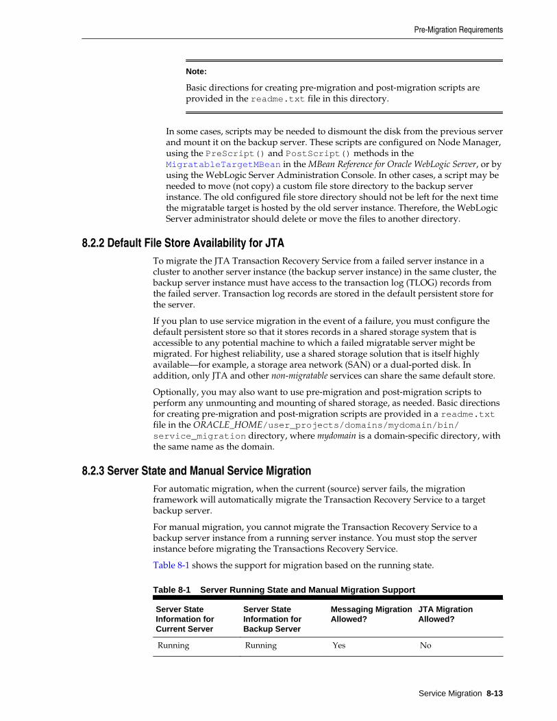
Note:
Basic directions for creating pre-migration and post-migration scripts areprovided in the readme.txt file in this directory.
In some cases, scripts may be needed to dismount the disk from the previous serverand mount it on the backup server. These scripts are configured on Node Manager,using the PreScript() and PostScript() methods in the MigratableTargetMBean in the MBean Reference for Oracle WebLogic Server, or byusing the WebLogic Server Administration Console. In other cases, a script may beneeded to move (not copy) a custom file store directory to the backup serverinstance. The old configured file store directory should not be left for the next timethe migratable target is hosted by the old server instance. Therefore, the WebLogicServer administrator should delete or move the files to another directory.
8.2.2 Default File Store Availability for JTATo migrate the JTA Transaction Recovery Service from a failed server instance in acluster to another server instance (the backup server instance) in the same cluster, thebackup server instance must have access to the transaction log (TLOG) records fromthe failed server. Transaction log records are stored in the default persistent store forthe server.
If you plan to use service migration in the event of a failure, you must configure thedefault persistent store so that it stores records in a shared storage system that isaccessible to any potential machine to which a failed migratable server might bemigrated. For highest reliability, use a shared storage solution that is itself highlyavailable—for example, a storage area network (SAN) or a dual-ported disk. Inaddition, only JTA and other non-migratable services can share the same default store.
Optionally, you may also want to use pre-migration and post-migration scripts toperform any unmounting and mounting of shared storage, as needed. Basic directionsfor creating pre-migration and post-migration scripts are provided in a readme.txtfile in the ORACLE_HOME/user_projects/domains/mydomain/bin/service_migration directory, where mydomain is a domain-specific directory, withthe same name as the domain.
8.2.3 Server State and Manual Service MigrationFor automatic migration, when the current (source) server fails, the migrationframework will automatically migrate the Transaction Recovery Service to a targetbackup server.
For manual migration, you cannot migrate the Transaction Recovery Service to abackup server instance from a running server instance. You must stop the serverinstance before migrating the Transactions Recovery Service.
Table 8-1 shows the support for migration based on the running state.
Table 8-1 Server Running State and Manual Migration Support
Server StateInformation forCurrent Server
Server StateInformation forBackup Server
Messaging MigrationAllowed?
JTA MigrationAllowed?
Running Running Yes No
Pre-Migration Requirements
Service Migration 8-13
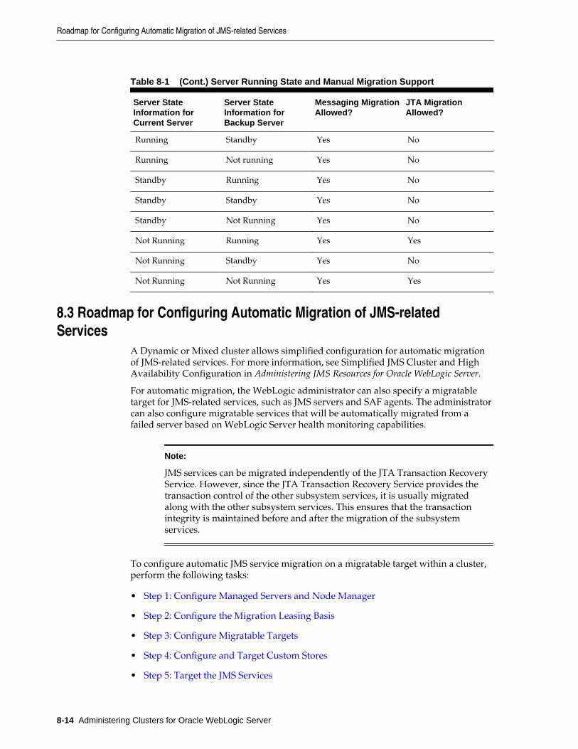
Table 8-1 (Cont.) Server Running State and Manual Migration Support
Server StateInformation forCurrent Server
Server StateInformation forBackup Server
Messaging MigrationAllowed?
JTA MigrationAllowed?
Running Standby Yes No
Running Not running Yes No
Standby Running Yes No
Standby Standby Yes No
Standby Not Running Yes No
Not Running Running Yes Yes
Not Running Standby Yes No
Not Running Not Running Yes Yes
8.3 Roadmap for Configuring Automatic Migration of JMS-relatedServices
A Dynamic or Mixed cluster allows simplified configuration for automatic migrationof JMS-related services. For more information, see Simplified JMS Cluster and HighAvailability Configuration in Administering JMS Resources for Oracle WebLogic Server.
For automatic migration, the WebLogic administrator can also specify a migratabletarget for JMS-related services, such as JMS servers and SAF agents. The administratorcan also configure migratable services that will be automatically migrated from afailed server based on WebLogic Server health monitoring capabilities.
Note:
JMS services can be migrated independently of the JTA Transaction RecoveryService. However, since the JTA Transaction Recovery Service provides thetransaction control of the other subsystem services, it is usually migratedalong with the other subsystem services. This ensures that the transactionintegrity is maintained before and after the migration of the subsystemservices.
To configure automatic JMS service migration on a migratable target within a cluster,perform the following tasks:
• Step 1: Configure Managed Servers and Node Manager
• Step 2: Configure the Migration Leasing Basis
• Step 3: Configure Migratable Targets
• Step 4: Configure and Target Custom Stores
• Step 5: Target the JMS Services
Roadmap for Configuring Automatic Migration of JMS-related Services
8-14 Administering Clusters for Oracle WebLogic Server
• Step 6: Restart the Administration Server and Managed Servers With ModifiedMigration Policies
• Step 7: Manually Migrate JMS Services Back to the Original Server
8.3.1 Step 1: Configure Managed Servers and Node ManagerConfigure the Managed Servers in the cluster for migration, including assigningManaged Servers to a machine. In certain cases, Node Manager must also be runningand configured to allow automatic server migration.
For step-by-step instructions for using the WebLogic Server Administration Console tocomplete these tasks, refer to the following topics in the Oracle WebLogic ServerAdministration Console Online Help:
• Create Managed Servers
Note:
You must set a unique Listen Address value for the Managed Serverinstance that will host a migrated the JMS server. Otherwise, the migrationwill fail.
• Create and configure machines
• Configure Node Manager
Note:
For automatic service migration, Consensus leasing requires that you useNode Manager to control server instances within the cluster and that allmigratable servers must have a Node Manager instance associated with them.For Database leasing, Node Manager is required only if pre-migration andpost-migration scripts are defined. If pre-migration and post-migration scriptsare not defined, then Node Manager is not required.
For general information on configuring Node Manager, see Using Node Managerto Control Servers in Administering Node Manager for Oracle WebLogic Server.
8.3.2 Step 2: Configure the Migration Leasing BasisOn the Cluster > Configuration > Migration page in the WebLogic ServerAdministration Console, configure the cluster Migration Basis according to howyour data persistence environment is configured, selecting either DatabaseLeasing or Consensus Leasing. See Leasing for Migratable Services.
8.3.3 Step 3: Configure Migratable TargetsYou should perform this step before targeting any JMS-related services or enabling theJTA Transaction Recovery Service migration.
8.3.3.1 Configuring a Migratable Server as an Automatically Migratable Target
The Migratable Target Summary table in the WebLogic Server Administration Consoledisplays the system-generated migratable targets of servername (migratable), which are
Roadmap for Configuring Automatic Migration of JMS-related Services
Service Migration 8-15
automatically generated for each running server instance in a cluster. However, theseare only generic templates and still need to be targeted and configured for automaticmigration.
8.3.3.2 Create a New Migratable Target
When creating a new migratable target, the WebLogic Server Administration Consoleprovides a mechanism for creating, targeting, and selecting a migration policy.
8.3.3.2.1 Select a User Preferred Server
When you create a new migratable target using the WebLogic Server AdministrationConsole, you can initially choose a preferred server instance in the cluster on which toassociate the target. The User Preferred Server is the most appropriate server instancefor hosting the migratable target.
Note:
An automatically migrated service may not end up being hosted on thespecified User Preferred Server. In order to verify which server is hosting amigrated service, use the WebLogic Server Administration Console to checkthe Current Hosting Server information on the Migratable Target >Control page in the WebLogic Server Administration Console. For moreinformation, see Migratable Target: Control in Oracle WebLogic ServerAdministration Console Online Help.
8.3.3.2.2 Select a Service Migration Policy
The default migration policy for migratable targets is Manual Service MigrationOnly, so you must select one of the following auto-migration policies:
• Auto-Migrate Exactly-Once Services—Indicates that if at least one ManagedServer in the candidate list is running, then the service will be active somewhere inthe cluster if server instances should fail or are shut down (either gracefully orforcibly).
Note:
This value can lead to target grouping. For example, if you have fiveexactly-once migratable targets and only start one Managed Server in thecluster, then all five targets will be activated on that server instance.
• Auto-Migrate Failure-Recovery Services—This policy indicates that the servicewill only start if its User Preferred Server (UPS) is started. If an administrator shutsdown the UPS either gracefully or forcibly, this service will not be migrated.However, if the UPS fails due to an internal error, the service will be migrated toanother candidate server instance. If such a candidate server instance is unavailable(due to a manual shutdown or an internal failure), then the migration frameworkwill first attempt to reactivate the service on its UPS server. If the UPS server is notavailable at that time, then the service will be migrated to another candidate serverinstance.
See Policies for Manual and Automatic Service Migration.
Roadmap for Configuring Automatic Migration of JMS-related Services
8-16 Administering Clusters for Oracle WebLogic Server
8.3.3.2.3 Optionally Select Constrained Candidate Servers
When creating migratable targets that use the exactly-once services migrationpolicy, you may also want to restrict the potential member servers to which JMSservers can be migrated. A recommended best practice is to limit each migratabletarget's candidate server set to a primary, secondary, and perhaps a tertiary serverinstance. Then as each server starts, the migratable targets will be restricted to theircandidate server instances, rather than being satisfied by the first server instance tocome online. Administrators can then manually migrate services to idle serverinstances.
For the cluster's path service, however, the candidate server instances for themigratable target should be the entire cluster, which is the default setting.
On the migratable target Configuration > Migration page in the WebLogic ServerAdministration Console, the Constrained Candidate Servers Available box lists allof the Managed Servers that could possibly support the migratable target. TheManaged Servers become valid Candidate Servers when you move them into theChosen box.
8.3.3.2.4 Optionally Specify Pre/Post-Migration Scripts
After creating a migratable target, you may also want to specify whether you areproviding any pre-migration and post-migration scripts to perform any unmountingand mounting of the shared custom file store, as needed.
• Pre-Migration Script Path—the path to the pre-migration script to run before amigratable target is actually activated.
• Post-Migration Script Path—the path to the post-migration script to run after amigratable target is fully deactivated.
• Post-Migration Script Failure Cancels Automatic Migration—specifies whether ornot a failure during execution of the post-deactivation script is fatal to themigration.
• Allow Post-Migration Script To Run On a Different Machine—specifies whetheror not the post-deactivation script is allowed to run on a different machine.
The pre-migration and post-migration scripts must be located in the ORACLE_HOME/user_projects/domains/mydomain/bin/service_migration directory,where mydomain is a domain-specific directory, with the same name as the domain.For your convenience, sample pre-migration and post-migration scripts are providedin this directory.
8.3.3.2.5 Optionally Specify In-Place Restart Options
Migratable targets provide restart-in-place options to attempt to deactivate andreactivate a failed service, instead of migrating the service. See In-Place Restarting ofFailed Migratable Services.
8.3.4 Step 4: Configure and Target Custom StoresAs discussed in Custom Store Availability for JMS Services, JMS-related servicesrequire you to configure a custom persistent store that is targeted to a dynamic clusteror to the same migratable targets as the JMS services. Ensure that the store is either:
• Configured such that all the candidate server instances in a migratable target haveaccess to the custom store.
Roadmap for Configuring Automatic Migration of JMS-related Services
Service Migration 8-17
• Migrated by pre-migration and post-migration scripts. See Optionally Specify Pre/Post-Migration Scripts.
8.3.5 Step 5: Target the JMS ServicesWhen using migratable targets, you must target your JMS service to the samemigratable target used by the custom persistent store. In the event that no customstore is specified for a JMS service that uses a migratable target, then a validationmessage will be generated, followed by failed JMS server deployment and a WebLogicServer boot failure. For example, attempting to target a JMS server that is using thedefault file store to a migratable target, will generate the following message:
Since the JMS server is targeted to a migratable target, it cannot use the default store.
Similar messages are generated for a SAF agent or path service that is targeted to amigratable target and attempts to use the default store. In addition, if the custom storeis not targeted to the same migratable target as the migratable service, then thefollowing validation log message will be generated, followed by failed JMS serverdeployment and a WebLogic Server start failure.
The JMS server is not targeted to the same target as its persistent store.
8.3.5.1 Special Considerations When Targeting SAF Agents or Path Service
There are some special targeting choices to consider when targeting SAF agents and apath service to migratable targets. For more information, see Targeting Rules for SAFAgents and Targeting Rules for Path Service.
8.3.6 Step 6: Restart the Administration Server and Managed Servers With ModifiedMigration Policies
You must restart the Administration Server after configuring your JMS services forautomatic service migration. You must also restart any Managed Servers whosemigration policies were modified.
8.3.7 Step 7: Manually Migrate JMS Services Back to the Original ServerYou may want to migrate a JMS service back to the original primary server instanceonce it is back online. Unlike the JTA Transaction Recovery Service, JMS services donot automatically migrate back to the primary server instance when it becomesavailable, so you need to manually migrate these services.
For instructions on manually migrating the JMS-related services using the WebLogicServer Administration Console, see Manually migrate JMS-related services in theOracle WebLogic Server Administration Console Online Help.
For instructions on manually migrating the JMS-related services using WLST, see WLST Command and Variable Reference in WLST Command Reference for WebLogicServer.
8.4 Best Practices for Targeting JMS when Configuring Automatic ServiceMigration
• In most cases, it is sufficient to use the default migratable target for a serverinstance. There is one default migratable target per server instance. An alternative
Best Practices for Targeting JMS when Configuring Automatic Service Migration
8-18 Administering Clusters for Oracle WebLogic Server
is to configure one migratable target per server instance. See Step 3: ConfigureMigratable Targets.
• Configure one custom store per migratable target and target the store to themigratable target. See Step 4: Configure and Target Custom Stores.
• When configuring JMS services (JMS servers and SAF agents) for each migratabletarget, ensure that the services refer to the corresponding custom store. Then targetthe services to each migratable target. See Step 5: Target the JMS Services.
• Use JMS system modules rather than deployment modules. The WebLogic ServerAdministration Console only provides the ability to configure system modules. See JMS System Module Configuration in Administering JMS Resources for OracleWebLogic Server.
• Create one system module per anticipated target set, and target the module to asingle cluster. For example, if you plan to have one destination that spans a singleJMS server and another destination that spans six JMS servers, create two modulesand target both of them to the same cluster.
• Configure one subdeployment per module and populate the subdeployment with ahomogeneous set of either JMS server of JMS SAF agent targets. Do not includeWebLogic Server or cluster names in the subdeployment.
• Target connection factories to clusters for applications running on the same cluster.You can use default targeting to inherit the module target. Target connectionfactories to a subdeployment by using the Advanced Targeting choice on theWebLogic Server Administration Console for use by applications running remoteto cluster.
• For other JMS module resources, such as destinations, target using asubdeployment. Do not use default targeting. Subdeployment targeting is availablethrough the Advanced Targeting choice on the WebLogic Server AdministrationConsole.
• As you add or remove JMS servers or SAF agents, remember to also add or removeJMS servers or SAF agents to your module subdeployment(s).
• Custom connection factories are used to control client behavior, such as loadbalancing. They are targeted just like any other resource, but in the case of aconnection factory, the target set has a special meaning. You can target aconnection factory to a cluster, WebLogic Server, or to a JMS server or SAF agent(using a subdeployment). There is a performance advantage to targetingconnection factories to the exact JMS servers or SAF agents that the client will use,as the target set for a connection factory determines the candidate set of host serverinstances for a client connection. Targeting to the exact JMS servers or SAF agentsreduces the likelihood that client connections will connect to server instances thatdo not have a JMS server or SAF agent in cases where there is not a SAF agent onevery clustered server instance. If no JMS server or SAF agent exists on aconnection host, the client request must always double-hop the route from theclient to the connection host server, then ultimately on to the JMS server or SAFagent.
See Best Practices for JMS Beginners and Advanced Users in Administering JMSResources for Oracle WebLogic Server.
Best Practices for Targeting JMS when Configuring Automatic Service Migration
Service Migration 8-19
8.5 Roadmap for Configuring Manual Migration of JMS-related ServicesWebLogic JMS leverages the migration framework by allowing an administrator tospecify a migratable target for JMS-related services. Once properly configured, a JMSservice can be manually migrated to another WebLogic Server within a cluster. Thisincludes both scheduled migrations as well as manual migrations in response to aWebLogic Server failure within the cluster.
To configure JMS-related services for manual migration on a migratable target withina cluster, perform the following tasks:
• Step 1: Configure Managed Servers
• Step 2: Configure Migratable Targets
• Step 3: Configure and Target Custom Stores
• Step 4: Target the JMS Services
• Step 5: Restart the Administration Server and Managed Servers With ModifiedMigration Policies
• Step 6: Manually Migrating JMS Services
8.5.1 Step 1: Configure Managed ServersConfigure the Managed Servers in the cluster for migration, including assigningManaged Servers to a machine.
For step-by-step instructions for using the WebLogic Server Administration Console tocomplete these tasks, refer to the following topics in Oracle WebLogic ServerAdministration Console Online Help:
• Create Managed Servers
Note:
You must set a unique Listen Address value for the Managed Serverinstance that will host a migrated JMS server. Otherwise, the migration willfail.
• Create and configure machines
8.5.2 Step 2: Configure Migratable TargetsYou should perform this step before targeting any JMS-related services or enabling theJTA Transaction Recovery Service migration.
8.5.2.1 Configuring a Migratable Server As a Migratable Target
The Migratable Target Summary table in the WebLogic Server Administration Consoledisplays the system-generated migratable targets of servername (migratable), which areautomatically generated for each running server instance in a cluster. However, theseare only generic templates and still need to be targeted and configured for migration.
Roadmap for Configuring Manual Migration of JMS-related Services
8-20 Administering Clusters for Oracle WebLogic Server
8.5.2.2 Create a New Migratable Target
When creating a new migratable target, the WebLogic Server Administration Consoleprovides a mechanism for creating, targeting, and selecting a migration policy.
8.5.2.2.1 Select a Preferred Server
When you create a new migratable target using the WebLogic Server AdministrationConsole, you can initially choose a preferred server in the cluster on which to associatethe target. The preferred server instance is the most appropriate server instance forhosting the migratable target.
8.5.2.2.2 Accept the Default Manual Service Migration Policy
The default migration policy for all migratable targets is Manual ServiceMigration Only, so no change is necessary.
8.5.2.2.3 Optionally Select Constrained Candidate Servers
When creating migratable targets you may also want to restrict the potential serverinstances to which you can migrate JMS-related services to only those that have accessto a custom persistent store that is targeted to the same migratable target as the JMS-related services.
For the cluster's path service, however, the candidate server instances for themigratable target should be the entire cluster, which is the default setting.
On the migratable target Configuration > Migration page in the WebLogic ServerAdministration Console, the Constrained Candidate Servers Available box lists allof the Managed Servers that could possibly support the migratable target. TheManaged Servers become valid Candidate Servers when you move them into theChosen box.
8.5.2.2.4 Optionally Specify Pre/Post-Migration Scripts
After creating a migratable target, you may also want to specify whether you areproviding any pre-migration and post-migration scripts to perform any unmountingand mounting of the shared custom store, as needed.
• Pre-Migration Script Path—the path to the pre-migration script to run before amigratable target is actually activated.
• Post-Migration Script Path—the path to the post-migration script to run after amigratable target is fully deactivated.
• Post-Migration Script Failure Cancels Automatic Migration—specifies whether ornot a failure during execution of the post-deactivation script is fatal to themigration.
• Allow Post-Migration Script To Run On a Different Machine—specifies whetheror not the post-deactivation script is allowed to run on a different machine.
The pre-migration and post-migration scripts must be located in the ORACLE_HOME/user_projects/domains/mydomain/bin/service_migration directory,where mydomain is a domain-specific directory, with the same name as the domain.Basic directions for creating pre-migration and post-migration scripts are provided ina readme.txt file in this directory.
Roadmap for Configuring Manual Migration of JMS-related Services
Service Migration 8-21
8.5.2.2.5 Optionally Specify In-Place Restart Options
Migratable targets provide restart-in-place options to attempt to deactivate andreactivate a failed service, instead of migrating the service. See In-Place Restarting ofFailed Migratable Services.
8.5.3 Step 3: Configure and Target Custom StoresAs discussed in Custom Store Availability for JMS Services, JMS-related servicesrequire you to configure a custom persistent store that is also targeted to the samemigratable targets as the JMS services. Ensure that the store is either:
• Configured such that all the candidate server instances in a migratable target haveaccess to the custom store.
• Migrated by pre-migration and post-migration scripts. See Optionally Specify Pre/Post-Migration Scripts.
8.5.4 Step 4: Target the JMS ServicesJMS services can be targeted to a dynamic cluster, provided the custom store used isalso targeted to the same dynamic cluster.
When using migratable targets, you must target your JMS service to the samemigratable target used by the custom persistent store. In the event that no customstore is specified for a JMS service that uses a migratable target, a validation messagewill be generated, followed by failed JMS server deployment and a WebLogic Serverstart failure. For example, attempting to target a JMS server that is using the defaultfile store to a migratable target, will generate the following message:
Since the JMS server is targeted to a migratable target, it cannot use the default store.
Similar messages are generated for a SAF agent or path service that is targeted to amigratable target and attempts to use the default store.
In addition, if the custom store is not targeted to the same migratable target as themigratable service, then the following validation log message will be generated,followed by failed JMS server deployment and a WebLogic Server start failure.
The JMS server is not targeted to the same target as its persistent store.
8.5.4.1 Special Considerations When Targeting SAF Agents or Path Service
There are some special targeting choices to consider when targeting SAF agents and apath service to migratable targets. For more information, see Targeting Rules for SAFAgents and Targeting Rules for Path Service.
8.5.5 Step 5: Restart the Administration Server and Managed Servers With ModifiedMigration Policies
You must restart the Administration Server after configuring your JMS services formanual service migration.
You must also restart any Managed Servers whose migration policies were modified.
Roadmap for Configuring Manual Migration of JMS-related Services
8-22 Administering Clusters for Oracle WebLogic Server
8.5.6 Step 6: Manually Migrating JMS ServicesFor instructions on manually migrating the JMS-related services using the WebLogicServer Administration Console, see Manually migrate JMS-related services in theOracle WebLogic Server Administration Console Online Help.
For instructions on manually migrating the JMS-related services using WLST, see theWLST Command Reference for WebLogic Server.
Note:
You may want to migrate a JMS service back to the original primary serverinstance once it is back online. Unlike the JTA Transaction Recovery Service,JMS services do not automatically migrate back to the primary server instancewhen it becomes available, so you need to manually migrate these services.
8.6 Roadmap for Configuring Automatic Migration of the JTA TransactionRecovery Service
The JTA Transaction Recovery Service is designed to gracefully handle transactionrecovery after a crash. You can specify to have the Transaction Recovery Serviceautomatically migrated from an unhealthy server instance to a healthy server instance,with the help of the server health monitoring services. This way, the backup serverinstance can complete transaction work for the failed server instance.
To configure automatic migration of the Transaction Recovery Service for a migratabletarget within a cluster, perform the following tasks:
• Step 1: Configure Managed Servers and Node Manager
• Step 2: Configure the Migration Basis
• Step 3: Enable Automatic JTA Migration
• Step 4: Configure the Default Persistent Store For Transaction Recovery ServiceMigration
• Step 5: Restart the Administration Server and Managed Servers With ModifiedMigration Policies
• Step 6: Automatic Failback of the Transaction Recovery Service Back to the OriginalServer
8.6.1 Step 1: Configure Managed Servers and Node ManagerConfigure the Managed Servers in the cluster for migration, including assigningManaged Servers to a machine. Node Manager must also be running and configuredto allow automatic server migration. Node Manager is required for health statusinformation about the server instances involved.
For step-by-step instructions for using the WebLogic Server Administration Console tocomplete these tasks, refer to the following topics in Administration Console OnlineHelp:
• Create Managed Servers
Roadmap for Configuring Automatic Migration of the JTA Transaction Recovery Service
Service Migration 8-23
Note:
– You must set a unique Listen Address value for the Managed Serverinstance that will host the JTA Transaction Recovery service. Otherwise,the migration will fail.
– For information on configuring a primary server instance to not start inManaged Server Independence (MSI) mode, which will prevent concurrentaccess to the transaction log with another backup server instance inrecovery mode, see Managed Server Independence in Developing JTAApplications for Oracle WebLogic Server.
• Create and configure machines
• Configure Node Manager
Note:
For automatic service migration, Consensus leasing requires that you useNode Manager to control server instances within the cluster and that allmigratable servers must have a Node Manager instance associated with them.For Database leasing, Node Manager is required only if pre-migration andpost-migration scripts are defined. If pre-migration and post-migration scriptsare not defined, then Node Manager is not required.
For general information on configuring Node Manager, see Node ManagerOverview in Administering Node Manager for Oracle WebLogic Server.
8.6.2 Step 2: Configure the Migration BasisOn the Cluster > Configuration > Migration page in the WebLogic ServerAdministration Console, configure the cluster Migration Basis according to howyour data persistence environment is configured, selecting either DatabaseLeasing or Consensus Leasing. See Leasing for Migratable Services.
8.6.3 Step 3: Enable Automatic JTA MigrationIn the JTA Migration Configuration section on the Server > Configuration >Migration page in the WebLogic Server Administration Console, configure thefollowing options:
8.6.3.1 Select the Automatic JTA Migration Policy
Select the migration policy for services hosted by the JTA migratable target. Validoptions are:
• Manual
• Failure Recovery
• Shutdown Recovery
Roadmap for Configuring Automatic Migration of the JTA Transaction Recovery Service
8-24 Administering Clusters for Oracle WebLogic Server
Note:
The Exactly Once migration policy does not apply for JTA.
For more information about these policies, see Servers: Configuration: Migration inOracle WebLogic Server Administration Console Online Help.
Configure the automatic migration of the JTA Transaction Recovery Service byselecting a migration policy for services hosted by the JTA migratable target from theJTA Migration Policy drop-down list.
8.6.3.2 Optionally Select Candidate Servers
You may also want to restrict the potential server instances to which you can migratethe Transaction Recovery Service to those that have access to the current serverinstance's transaction log files (stored in the default WebLogic store). If no candidateserver instances are chosen, then any server instance within the cluster can be chosenas a candidate server instance.
From the Candidate Servers Available box, select the Managed Servers that canaccess the JTA log files. The Managed Servers become valid Candidate Servers whenyou move them into the Chosen box.
Note:
You must include the original server instance in the list of chosen serverinstances so that you can manually migrate the Transaction Recovery Serviceback to the original server instance, if need be. The WebLogic ServerAdministration Console enforces this rule.
8.6.3.3 Optionally Specify Pre/Post-Migration Scripts
You can specify whether you are providing any pre-migration and post-migrationscripts to perform any unmounting and mounting of the shared storage, as needed.
• Pre-Migration Script Path—the path to the pre-migration script to run before amigratable target is actually activated.
• Post-Migration Script Path—the path to the post-migration script to run after amigratable target is fully deactivated.
• Post-Migration Script Failure Cancels Automatic Migration—specifies whether ornot a failure during execution of the post-deactivation script is fatal to themigration.
• Allow Post-Migration Script To Run On a Different Machine—specifies whetheror not the post-deactivation script is allowed to run on a different machine.
The pre-migration and post-migration scripts must be located in the ORACLE_HOME/user_projects/domains/mydomain/bin/service_migration directory,where mydomain is a domain-specific directory, with the same name as the domain.Basic directions for creating pre-migration and post-migration scripts are provided ina readme.txt file in this directory.
Roadmap for Configuring Automatic Migration of the JTA Transaction Recovery Service
Service Migration 8-25
8.6.4 Step 4: Configure the Default Persistent Store For Transaction Recovery ServiceMigration
As discussed in Default File Store Availability for JTA, the Transaction Manager usesthe default persistent store to store transaction log files. To enable migration of theTransaction Recovery Service, you must configure the default persistent store so that itstores its data files on a persistent storage solution that is available to other serverinstances in the cluster if the original server instance fails.
8.6.5 Step 5: Restart the Administration Server and Managed Servers With ModifiedMigration Policies
You must restart the Administration Server after configuring the JTA TransactionRecovery service for automatic service migration.
You must also restart any Managed Servers whose migration policies were modified.
8.6.6 Step 6: Automatic Failback of the Transaction Recovery Service Back to theOriginal Server
After completing transaction recovery for a failed server instance, a backup serverinstance releases ownership of the Transaction Recovery Service so that the originalserver instance can reclaim it when the server instance is restarted. If the backupserver stops (crashes) for any reason before it completes transaction recovery, its leasewill expire. This way when the primary server instance starts, it can reclaimsuccessfully ownership.
There are two scenarios for automatic failback of the Transaction Recovery Service tothe primary server instance:
• Automatic failback after recovery is complete:
– If the backup server instance finishes recovering the transaction log transactionsbefore the primary server instance is restarted, it will initiate an implicitmigration of the Transaction Recovery Service back to the primary serverinstance.
– For both manual and automatic migration, the post-deactivation script will beexecuted automatically.
• Automatic failback before recovery is complete:
– If the backup server instance is still recovering the transaction log transactionswhen the primary server instance is started, during the Transaction RecoveryService initialization of the primary server startup, it will initiate an implicitmigration of the Transaction Recovery Service from the backup server instance.
8.7 Manual Migration of the JTA Transaction Recovery ServiceThe JTA Transaction Recovery Service is designed to gracefully handle transactionrecovery after a crash. You can manually migrate the Transaction Recovery Servicefrom an unhealthy server instance to a healthy server instance, with the help of theserver health monitoring services. In this manner, the backup server instance cancomplete transaction work for the failed server instance.
Manual Migration of the JTA Transaction Recovery Service
8-26 Administering Clusters for Oracle WebLogic Server
You can manually migrate the Transaction Recovery Service back to the original serverinstance by selecting the original server instance as the destination server instance. Thebackup server instance must not be running when you manually migrate the serviceback to the original server instance.
Note the following:
• If a backup server instance fails before completing the transaction recovery actions,the primary server instance cannot reclaim ownership of the Transaction RecoveryService and recovery will not be re-attempted on the restarting server instance.Therefore, you must attempt to manually re-migrate the Transaction RecoveryService to another backup server instance.
• If you restart the original server instance while the backup server instance isrecovering transactions, the backup server instance will gracefully releaseownership of the Transaction Recovery Service. You do not need to stop thebackup server instance. For detailed information, see Recovering Transactions Fora Failed Clustered Server in Developing JTA Applications for Oracle WebLogic Server.
• For information on configuring a primary backup server instance to not start inManaged Server Independence (MSI) mode, which will prevent concurrent accessto the transaction log with another backup server in recovery mode, see ManagedServer Independence in Developing JTA Applications for Oracle WebLogic Server.
For instructions on manually migrating the Transaction Recovery Service using theWebLogic Server Administration Console, see Manually migrate the TransactionRecovery Service in Oracle WebLogic Server Administration Console Online Help.
8.8 Automatic Migration of User-Defined Singleton ServicesAutomatic singleton service migration allows the automatic health monitoring andmigration of singleton services. A singleton service is a service operating within acluster that is available on only one server instance at any given time. When amigratable service fails or become unavailable for any reason (for example, because ofa bug in the service code, server failure, or network failure), it is deactivated at itscurrent location and activated on a new server instance. The process of migratingthese services to another server instance is handled using the singleton master. See Singleton Master.
WebLogic Server supports the automatic migration of user-defined singleton services.
Note:
Although the JTA Transaction Recovery Service is also a singleton service thatis available on only one node of a cluster at any time, it is configureddifferently for automatic migration than user-defined singleton services. JMSand JTA services can also be manually migrated. See Understanding theService Migration Framework.
8.8.1 Overview of Singleton Service MigrationThis section provides an overview of how automatic singleton service is implementedin WebLogic Server.
Automatic Migration of User-Defined Singleton Services
Service Migration 8-27
8.8.1.1 Singleton Master
The singleton master is a lightweight singleton service that monitors other servicesthat can be migrated automatically. The server instance that currently hosts thesingleton master is responsible for starting and stopping the migration tasksassociated with each migratable service.
Note:
Migratable services do not have to be hosted on the same server instance asthe singleton master, but they must be hosted within the same cluster.
The singleton master functions similar to the cluster master in that it is maintained bylease competition and runs on only one server instance at a time. Each server instancein a cluster continuously attempts to register the singleton master lease. If the serverinstance currently hosting the singleton master fails, the next server instance in thequeue will take over the lease and begin hosting the singleton master.
For more information on the cluster master, see Cluster Master Role in Whole ServerMigration.
Note:
The singleton master and cluster master function independently and are notrequired to be hosted on the same server instance.
The server instance hosting the singleton master maintains a record of all migrationsperformed, including the target name, source server, destination server, and thetimestamp.
8.8.1.2 Migration Failure
If the migration of a singleton service fails on every candidate server instance withinthe cluster, the service is left deactivated. You can configure the number of times thenumber of times the singleton master will iterate through the server instances in thecluster.
Note:
If you do not explicitly specify a list of candidate server instances, thesingleton master will consider all of the cluster members as possiblecandidates for migration.
8.8.2 Implementing the Singleton Service InterfaceA singleton service can be defined either as part of an application or as a standaloneservice. It is active only on one server instance at any time and so it can be used toperform tasks that you want to be executed on only one member of a cluster.
To create a singleton service, you must create a class that, in addition to any tasks youwant the singleton service to perform, implements theweblogic.cluster.singleton.SingletonService interface.
Automatic Migration of User-Defined Singleton Services
8-28 Administering Clusters for Oracle WebLogic Server
The SingletonService interface contains the following methods, which are used inthe process of migration.
• public void activate()
This method should obtain any system resources and start any services requiredfor the singleton service to begin processing requests. This method is called in thefollowing cases:
– When a newly deployed application is started
– During server start
– During the activation stage of service migration
• public void deactivate()
This method is called during server shutdown and during the deactivation stage ofsingleton service migration. This method should release any resources obtainedthrough the activate() method. Additionally, it should stop any services thatshould only be available from one member of a cluster.
8.8.3 Deploying a Singleton Service and Configuring the Migration BehaviorDepending on how you used the SingletonService interface to define a singletonservice, you must perform the following steps to deploy it:
• Package and deploy the singleton service within an application (application-scoped).
~ or ~
• Deploy the singleton service as a standalone service within WebLogic Server(domain-wide).
• Optionally, configure the migration behavior of the singleton service.
Note:
When you package and deploy an application-scoped singleton service, youcannot use the WebLogic Server Administration Console to control on whichManaged Server the service will be hosted. However, when you deploy adomain-wide singleton service, you can specify the server name, class name,and preferred Managed Server in the WebLogic Server AdministrationConsole.
The following sections outline these procedures in detail.
8.8.3.1 Packaging and Deploying a Singleton Service Within an Application
Singleton services that are packaged within an application should have their classesimplement the SingletonService interface and placed within a JAR file, in APP-INF/lib or APP-INF/classes, or within an EAR-level lib directory. JNDI bindingfor application-scoped singleton services is done programmatically in theSingletonService interface. The life cycle of an application-scoped singletonservice is tied with the life cycle of the application.
Automatic Migration of User-Defined Singleton Services
Service Migration 8-29
For standalone singleton services, their classes should be made available in theWebLogic Server system classpath.
Also, add the following entry to the weblogic-application.xml descriptor file:
<weblogic-application>... <singleton-service> <class-name>mypackage.MySingletonServiceImpl</class-name> <name>Appscoped_Singleton_Service</name> </singleton-service>...</weblogic-application>
Note:
The <class-name> and <name> elements are required.
Deployment of an application-scoped singleton service occurs automatically as part ofthe application deployment. The candidate server instances for the singleton servicewill be the cluster members where the application is deployed.
8.8.3.2 Deploying a Singleton Service as a Standalone Service in WebLogic Server
After you have created a singleton service class using the SingletonServiceinterface, you must define it as a singleton service within WebLogic Server. Thissingleton service object contains the following information:
• The path to the class to load as the singleton service.
• The preferred server instance and other candidate server instances for the singletonservice.
The following excerpt from the <cluster> element of config.xml file shows how asingleton service is defined:
<singleton-service> <name>SingletonTestServiceName</name> <user-preferred-server>myManaged1</user-preferred-server> <class-name>mycompany.myprogram.subpackage.SingletonTestServiceImpl</class-name> <cluster>myCluster</cluster></singleton-service>
8.8.3.3 Configuring Singleton Service Migration
A singleton service is automatically configured to be an exactly-once service,which indicates that if at least one Managed Server in the candidate list is running,then the service will be active somewhere in the cluster. You can modify certainsingleton service migration parameters using the following methods:
• WebLogic Server Administration Console—allows you to create and configuresingleton services. See Configure a singleton service in Oracle WebLogic ServerAdministration Console Online Help.
• WebLogic Scripting Tool (WLST)—allows you to configure automatic servicemigration using the MigratableTargetManagementMBean. See WLSTCommand and Variable Reference in WLST Command Reference for WebLogic Server.
Automatic Migration of User-Defined Singleton Services
8-30 Administering Clusters for Oracle WebLogic Server
9Cluster Architectures
This chapter describes alternative architectures for a WebLogic Server cluster.
This chapter includes the following sections:
• Architectural and Cluster Terminology
• Recommended Basic Architecture
• Recommended Multi-Tier Architecture
• Recommended Proxy Architectures
• Security Options for Cluster Architectures
9.1 Architectural and Cluster TerminologyThis section defines terms used in this document.
9.1.1 ArchitectureIn this context the architecture refers to how the tiers of an application are deployed toone or more clusters.
9.1.2 Web Application TiersA Web application is divided into several "tiers" that correspond to the logical servicesthe application provides. Because not all Web applications are alike, your applicationmay not utilize all of the tiers described below. Also keep in mind that the tiersrepresent logical divisions of an application's services, and not necessarily physicaldivisions between hardware or software components. In some cases, a single machinerunning a single WebLogic Server instance can provide all of the tiers describedbelow.
• Web Tier
The Web tier provides static content (for example, simple HTML pages) to clients ofa Web application. The Web tier is generally the first point of contact betweenexternal clients and the Web application. A simple Web application may have aWeb tier that consists of one or more machines running Apache, NetscapeEnterprise Server, or Microsoft Internet Information Server.
• Presentation Tier
The presentation tier provides dynamic content (for example, servlets or Java ServerPages) to clients of a Web application. A cluster of WebLogic Server instances thathosts servlets and/or JSPs comprises the presentation tier of a Web application. Ifthe cluster also serves static HTML pages for your application, it encompasses boththe Web tier and the presentation tier.
Cluster Architectures 9-1

• Object Tier
The object tier provides Java objects (for example, Enterprise JavaBeans or RMIclasses) and their associated business logic to a Web application. A WebLogicServer cluster that hosts EJBs provides an object tier.
9.1.3 Combined Tier ArchitectureA cluster architecture in which all tiers of the Web application are deployed to a singleWebLogic Server cluster is called a combined tier architecture.
9.1.4 De-Militarized Zone (DMZ)The De-Militarized Zone (DMZ) is a logical collection of hardware and services that ismade available to outside, untrusted sources. In most Web applications, a bank of Webservers resides in the DMZ to allow browser-based clients access to static HTMLcontent.
The DMZ may provide security against outside attacks to hardware and software.However, because the DMZ is available to untrusted sources, it is less secure than aninternal system. For example, internal systems may be protected by a firewall thatdenies all outside access. The DMZ may be protected by a firewall that hides access toindividual machines, applications, or port numbers, but it still permits access to thoseservices from untrusted clients.
9.1.5 Load BalancerIn this document, the term load balancer describes any technology that distributes clientconnection requests to one or more distinct IP addresses. For example, a simple Webapplication may use the DNS round-robin algorithm as a load balancer. Largerapplications generally use hardware-based load balancing solutions such as thosefrom Alteon WebSystems, which may also provide firewall-like security capabilities.
Load balancers provide the capability to associate a client connection with a particularserver in the cluster, which is required when using in-memory replication for clientsession information. With certain load balancing products, you must configure thecookie persistence mechanism to avoid overwriting the WebLogic Server cookie whichtracks primary and secondary servers used for in-memory replication. See LoadBalancing HTTP Sessions with an External Load Balancer, for more information.
9.1.6 Proxy Plug-InA proxy plug-in is a WebLogic Server extension to an HTTP server—such as Apache,Netscape Enterprise Server, or Microsoft Internet Information Server—that accessesclustered servlets provided by a WebLogic Server cluster. The proxy plug-in containsthe load balancing logic for accessing servlets and JSPs in a WebLogic Server cluster.Proxy plug-ins also contain the logic for accessing the replica of a client's session stateif the primary WebLogic Server hosting the session state fails.
9.2 Recommended Basic ArchitectureThe recommended basic architecture is a combined tier architecture—all tiers of theWeb application are deployed to the same WebLogic Server cluster. This architectureis illustrated in Figure 9-1, below.
Recommended Basic Architecture
9-2 Administering Clusters for Oracle WebLogic Server
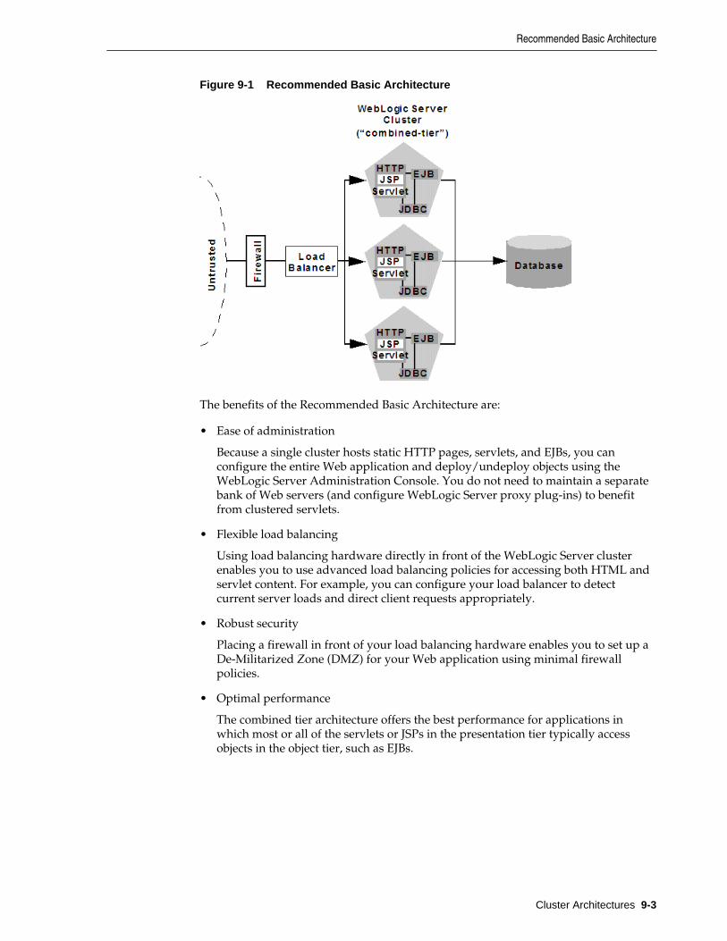
Figure 9-1 Recommended Basic Architecture
The benefits of the Recommended Basic Architecture are:
• Ease of administration
Because a single cluster hosts static HTTP pages, servlets, and EJBs, you canconfigure the entire Web application and deploy/undeploy objects using theWebLogic Server Administration Console. You do not need to maintain a separatebank of Web servers (and configure WebLogic Server proxy plug-ins) to benefitfrom clustered servlets.
• Flexible load balancing
Using load balancing hardware directly in front of the WebLogic Server clusterenables you to use advanced load balancing policies for accessing both HTML andservlet content. For example, you can configure your load balancer to detectcurrent server loads and direct client requests appropriately.
• Robust security
Placing a firewall in front of your load balancing hardware enables you to set up aDe-Militarized Zone (DMZ) for your Web application using minimal firewallpolicies.
• Optimal performance
The combined tier architecture offers the best performance for applications inwhich most or all of the servlets or JSPs in the presentation tier typically accessobjects in the object tier, such as EJBs.
Recommended Basic Architecture
Cluster Architectures 9-3
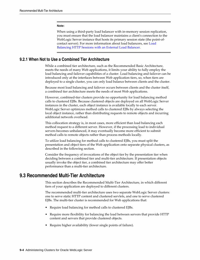
Note:
When using a third-party load balancer with in-memory session replication,you must ensure that the load balancer maintains a client's connection to theWebLogic Server instance that hosts its primary session state (the point-of-contact server). For more information about load balancers, see LoadBalancing HTTP Sessions with an External Load Balancer.
9.2.1 When Not to Use a Combined Tier ArchitectureWhile a combined tier architecture, such as the Recommended Basic Architecture,meets the needs of many Web applications, it limits your ability to fully employ theload balancing and failover capabilities of a cluster. Load balancing and failover can beintroduced only at the interfaces between Web application tiers, so, when tiers aredeployed to a single cluster, you can only load balance between clients and the cluster.
Because most load balancing and failover occurs between clients and the cluster itself,a combined tier architecture meets the needs of most Web applications.
However, combined-tier clusters provide no opportunity for load balancing methodcalls to clustered EJBs. Because clustered objects are deployed on all WebLogic Serverinstances in the cluster, each object instance is available locally to each server.WebLogic Server optimizes method calls to clustered EJBs by always selecting thelocal object instance, rather than distributing requests to remote objects and incurringadditional network overhead.
This collocation strategy is, in most cases, more efficient than load balancing eachmethod request to a different server. However, if the processing load to individualservers becomes unbalanced, it may eventually become more efficient to submitmethod calls to remote objects rather than process methods locally.
To utilize load balancing for method calls to clustered EJBs, you must split thepresentation and object tiers of the Web application onto separate physical clusters, asdescribed in the following section.
Consider the frequency of invocations of the object tier by the presentation tier whendeciding between a combined tier and multi-tier architecture. If presentation objectsusually invoke the object tier, a combined tier architecture may offer betterperformance than a multi-tier architecture.
9.3 Recommended Multi-Tier ArchitectureThis section describes the Recommended Multi-Tier Architecture, in which differenttiers of your application are deployed to different clusters.
The recommended multi-tier architecture uses two separate WebLogic Server clusters:one to serve static HTTP content and clustered servlets, and one to serve clusteredEJBs. The multi-tier cluster is recommended for Web applications that:
• Require load balancing for method calls to clustered EJBs.
• Require more flexibility for balancing the load between servers that provide HTTPcontent and servers that provide clustered objects.
• Require higher availability (fewer single points of failure).
Recommended Multi-Tier Architecture
9-4 Administering Clusters for Oracle WebLogic Server
Note:
Consider the frequency of invocations from the presentation tier to the objecttier when considering a multi-tier architecture. If presentation objects usuallyinvoke the object tier, a combined tier architecture may offer betterperformance than a multi-tier architecture.
Figure 9-2 depicts the recommended multi-tier architecture.
Figure 9-2 Recommended Multi-Tier Architecture
9.3.1 Physical Hardware and Software LayersIn the Recommended Multi-Tier Architecture the application tiers are hosted on twoseparate physical layers of hardware and software.
9.3.1.1 Web/Presentation Layer
The Web/presentation layer consists of a cluster of WebLogic Server instancesdedicated to hosting static HTTP pages, servlets, and JSPs. This servlet cluster does nothost clustered objects. Instead, servlets in the presentation tier cluster act as clients forclustered objects, which reside on an separate WebLogic Server cluster in the objectlayer.
9.3.1.2 Object Layer
The object layer consists of a cluster of WebLogic Server instances that hosts onlyclustered objects—EJBs and RMI objects as necessary for the Web application. Byhosting the object tier on a dedicated cluster, you lose the default collocationoptimization for accessing clustered objects described in Optimization for CollocatedObjects. However, you gain the ability to load balance on each method call to certainclustered objects, as described in the following section.
Recommended Multi-Tier Architecture
Cluster Architectures 9-5
9.3.2 Benefits of Multi-Tier ArchitectureThe multi-tier architecture provides these advantages:
• Load Balancing EJB Methods
By hosting servlets and EJBs on separate clusters, servlet method calls to EJBs canbe load balanced across multiple servers. This process is described in detail in LoadBalancing Clustered Objects in a in Multi-Tier Architecture.
• Improved Server Load Balancing
Separating the presentation and object tiers onto separate clusters provides moreoptions for distributing the load of the Web application. For example, if theapplication accesses HTTP and servlet content more often than EJB content, youcan use a large number of WebLogic Server instances in the presentation tiercluster to concentrate access to a smaller number of servers hosting EJBs.
• Higher Availability
By utilizing additional WebLogic Server instances, the multi-tier architecture hasfewer points of failure than the basic cluster architecture. For example, if aWebLogic Server that hosts EJBs fails, the HTTP- and servlet-hosting capacity ofthe Web application is not affected.
• Improved Security Options
By separating the presentation and object tiers onto separate clusters, you can use afirewall policy that places only the servlet/JSP cluster in the DMZ. Servers hostingclustered objects can be further protected by denying direct access from untrustedclients. For more information, see Security Options for Cluster Architectures.
9.3.3 Load Balancing Clustered Objects in a in Multi-Tier ArchitectureWebLogic Server's collocation optimization for clustered objects, described in Optimization for Collocated Objects, relies on having a clustered object (the EJB orRMI class) hosted on the same server instance as the replica-aware stub that calls theobject.
The net effect of isolating the object tier is that no client (HTTP client, Java client, orservlet) ever acquires a replica-aware stub on the same server that hosts the clusteredobject. Because of this, WebLogic Server cannot use its collocation optimization(described in Optimization for Collocated Objects), and servlet calls to clusteredobjects are automatically load balanced according to the logic contained in the replica-aware stub. Figure 9-3 depicts a client accessing a clustered EJB instance in the multi-tier architecture.
Recommended Multi-Tier Architecture
9-6 Administering Clusters for Oracle WebLogic Server
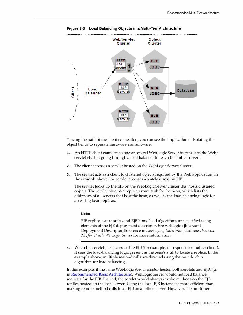
Figure 9-3 Load Balancing Objects in a Multi-Tier Architecture
Tracing the path of the client connection, you can see the implication of isolating theobject tier onto separate hardware and software:
1. An HTTP client connects to one of several WebLogic Server instances in the Web/servlet cluster, going through a load balancer to reach the initial server.
2. The client accesses a servlet hosted on the WebLogic Server cluster.
3. The servlet acts as a client to clustered objects required by the Web application. Inthe example above, the servlet accesses a stateless session EJB.
The servlet looks up the EJB on the WebLogic Server cluster that hosts clusteredobjects. The servlet obtains a replica-aware stub for the bean, which lists theaddresses of all servers that host the bean, as well as the load balancing logic foraccessing bean replicas.
Note:
EJB replica-aware stubs and EJB home load algorithms are specified usingelements of the EJB deployment descriptor. See weblogic-ejb-jar.xmlDeployment Descriptor Reference in Developing Enterprise JavaBeans, Version2.1, for Oracle WebLogic Server for more information.
4. When the servlet next accesses the EJB (for example, in response to another client),it uses the load-balancing logic present in the bean's stub to locate a replica. In theexample above, multiple method calls are directed using the round-robinalgorithm for load balancing.
In this example, if the same WebLogic Server cluster hosted both servlets and EJBs (asin Recommended Basic Architecture), WebLogic Server would not load balancerequests for the EJB. Instead, the servlet would always invoke methods on the EJBreplica hosted on the local server. Using the local EJB instance is more efficient thanmaking remote method calls to an EJB on another server. However, the multi-tier
Recommended Multi-Tier Architecture
Cluster Architectures 9-7
architecture enables remote EJB access for applications that require load balancing forEJB method calls.
9.3.4 Configuration Considerations for Multi-Tier ArchitectureA multi-tier architecture may require adjustments to the configuration, as described inthe following sections.
9.3.4.1 IP Socket Usage
Because the multi-tier architecture provides load balancing for clustered object calls,the system generally utilizes more IP sockets than a combined-tier architecture. Inparticular, during peak socket usage, each WebLogic Server instance in the cluster thathosts servlets and JSPs may potentially use a maximum of:
• One socket for replicating HTTP session states between primary and secondaryservers, plus
• One socket for each WebLogic Server in the EJB cluster, for accessing remoteobjects
For example, in Figure 9-2, each server in the servlet/JSP cluster could potentiallyopen a maximum of five sockets. This maximum represents a worst-case scenariowhere primary and secondary session states are equally dispersed throughout theservlet cluster, and each server in the servlet cluster simultaneously accesses a remoteobject on each server in the object cluster. In most cases, the number of actual socketsin use would be less than this maximum.
If you use a pure-Java sockets implementation with the multi-tier architecture, ensurethat you configure enough socket reader threads to accommodate the maximumpotential socket usage. For details, see Configuring Reader Threads for Java SocketImplementation.
9.3.4.2 Hardware Load Balancers
Because the multi-tier architecture uses a hardware load balancer, you must configurethe load balancer to maintain a "sticky" connection to the client's point-of-contactserver if you use in-memory session state replication. For details, see Configure LoadBalancing Method for EJBs and RMIs .
9.3.5 Limitations of Multi-Tier ArchitecturesThis section summarizes the limitations of multi-tier cluster architectures.
9.3.5.1 No Collocation Optimization
Because the Recommended Multi-Tier Architecture cannot optimize object calls usingthe collocation strategy, the Web application incurs network overhead for all methodcalls to clustered objects. This overhead may be acceptable, however, if your Webapplication requires any of the benefits described in Benefits of Multi-TierArchitecture.
For example, if your Web clients make heavy use of servlets and JSPs but access arelatively small set of clustered objects, the multi-tier architecture enables you toconcentrate the load of servlets and object appropriately. You may configure a servletcluster of ten WebLogic Server instances and an object cluster of three WebLogicServer instances, while still fully utilizing each server's processing power.
Recommended Multi-Tier Architecture
9-8 Administering Clusters for Oracle WebLogic Server
9.3.5.2 Firewall Restrictions
If you place a firewall between the servlet cluster and object cluster in a multi-tierarchitecture, you must bind all servers in the object cluster to public DNS names,rather than IP addresses. Binding those servers with IP addresses can cause addresstranslation problems and prevent the servlet cluster from accessing individual serverinstances.
If the internal and external DNS names of a WebLogic Server instance are notidentical, use the ExternalDNSName attribute for the server instance to define theserver's external DNS name. Outside the firewall the ExternalDNSName shouldtranslate to external IP address of the server.
Use of ExternalDNSName is required for configurations in which a firewall isperforming Network Address Translation, unless clients are accessing WebLogicServer using t3 and the default channel. For instance, ExternalDNSName is requiredfor configurations in which a firewall is performing Network Address Translation,and clients are accessing WebLogic Server using HTTP via a proxy plug-in.
9.4 Recommended Proxy ArchitecturesYou can configure WebLogic Server clusters to operate alongside existing Webservers. In such an architecture, a bank of Web servers provides static HTTP contentfor the Web application, using a WebLogic proxy plug-in or HttpClusterServletto direct servlet and JSP requests to a cluster.
The following sections describe two alternative proxy architectures.
9.4.1 Two-Tier Proxy ArchitectureThe two-tier proxy architecture illustrated in Figure 9-4 is similar to the Recommended Basic Architecture, except that static HTTP servers are hosted on abank of Web servers.
Recommended Proxy Architectures
Cluster Architectures 9-9
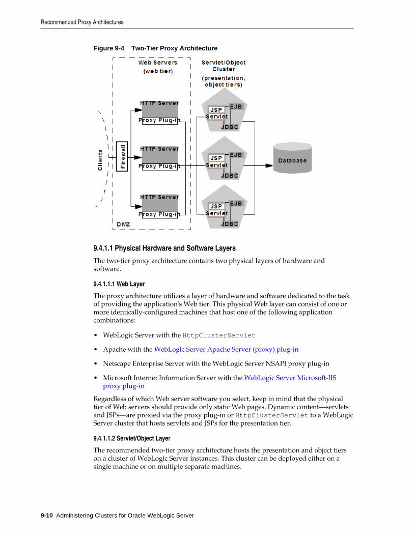
Figure 9-4 Two-Tier Proxy Architecture
9.4.1.1 Physical Hardware and Software Layers
The two-tier proxy architecture contains two physical layers of hardware andsoftware.
9.4.1.1.1 Web Layer
The proxy architecture utilizes a layer of hardware and software dedicated to the taskof providing the application's Web tier. This physical Web layer can consist of one ormore identically-configured machines that host one of the following applicationcombinations:
• WebLogic Server with the HttpClusterServlet
• Apache with the WebLogic Server Apache Server (proxy) plug-in
• Netscape Enterprise Server with the WebLogic Server NSAPI proxy plug-in
• Microsoft Internet Information Server with the WebLogic Server Microsoft-IISproxy plug-in
Regardless of which Web server software you select, keep in mind that the physicaltier of Web servers should provide only static Web pages. Dynamic content—servletsand JSPs—are proxied via the proxy plug-in or HttpClusterServlet to a WebLogicServer cluster that hosts servlets and JSPs for the presentation tier.
9.4.1.1.2 Servlet/Object Layer
The recommended two-tier proxy architecture hosts the presentation and object tierson a cluster of WebLogic Server instances. This cluster can be deployed either on asingle machine or on multiple separate machines.
Recommended Proxy Architectures
9-10 Administering Clusters for Oracle WebLogic Server
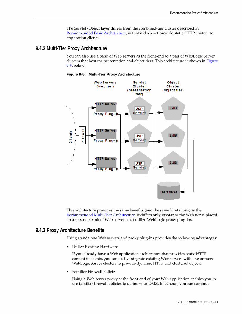
The Servlet/Object layer differs from the combined-tier cluster described in Recommended Basic Architecture, in that it does not provide static HTTP content toapplication clients.
9.4.2 Multi-Tier Proxy ArchitectureYou can also use a bank of Web servers as the front-end to a pair of WebLogic Serverclusters that host the presentation and object tiers. This architecture is shown in Figure9-5, below.
Figure 9-5 Multi-Tier Proxy Architecture
This architecture provides the same benefits (and the same limitations) as the Recommended Multi-Tier Architecture. It differs only insofar as the Web tier is placedon a separate bank of Web servers that utilize WebLogic proxy plug-ins.
9.4.3 Proxy Architecture BenefitsUsing standalone Web servers and proxy plug-ins provides the following advantages:
• Utilize Existing Hardware
If you already have a Web application architecture that provides static HTTPcontent to clients, you can easily integrate existing Web servers with one or moreWebLogic Server clusters to provide dynamic HTTP and clustered objects.
• Familiar Firewall Policies
Using a Web server proxy at the front-end of your Web application enables you touse familiar firewall policies to define your DMZ. In general, you can continue
Recommended Proxy Architectures
Cluster Architectures 9-11
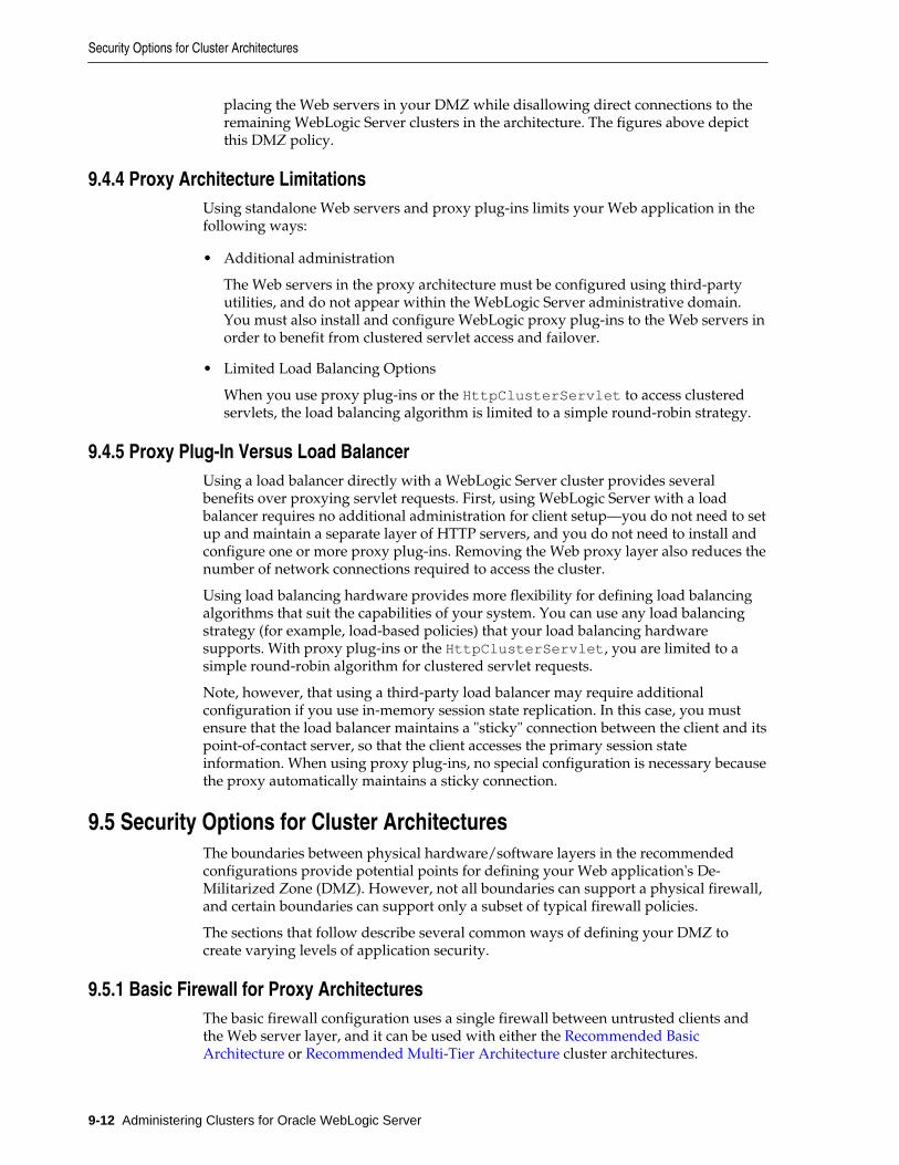
placing the Web servers in your DMZ while disallowing direct connections to theremaining WebLogic Server clusters in the architecture. The figures above depictthis DMZ policy.
9.4.4 Proxy Architecture LimitationsUsing standalone Web servers and proxy plug-ins limits your Web application in thefollowing ways:
• Additional administration
The Web servers in the proxy architecture must be configured using third-partyutilities, and do not appear within the WebLogic Server administrative domain.You must also install and configure WebLogic proxy plug-ins to the Web servers inorder to benefit from clustered servlet access and failover.
• Limited Load Balancing Options
When you use proxy plug-ins or the HttpClusterServlet to access clusteredservlets, the load balancing algorithm is limited to a simple round-robin strategy.
9.4.5 Proxy Plug-In Versus Load BalancerUsing a load balancer directly with a WebLogic Server cluster provides severalbenefits over proxying servlet requests. First, using WebLogic Server with a loadbalancer requires no additional administration for client setup—you do not need to setup and maintain a separate layer of HTTP servers, and you do not need to install andconfigure one or more proxy plug-ins. Removing the Web proxy layer also reduces thenumber of network connections required to access the cluster.
Using load balancing hardware provides more flexibility for defining load balancingalgorithms that suit the capabilities of your system. You can use any load balancingstrategy (for example, load-based policies) that your load balancing hardwaresupports. With proxy plug-ins or the HttpClusterServlet, you are limited to asimple round-robin algorithm for clustered servlet requests.
Note, however, that using a third-party load balancer may require additionalconfiguration if you use in-memory session state replication. In this case, you mustensure that the load balancer maintains a "sticky" connection between the client and itspoint-of-contact server, so that the client accesses the primary session stateinformation. When using proxy plug-ins, no special configuration is necessary becausethe proxy automatically maintains a sticky connection.
9.5 Security Options for Cluster ArchitecturesThe boundaries between physical hardware/software layers in the recommendedconfigurations provide potential points for defining your Web application's De-Militarized Zone (DMZ). However, not all boundaries can support a physical firewall,and certain boundaries can support only a subset of typical firewall policies.
The sections that follow describe several common ways of defining your DMZ tocreate varying levels of application security.
9.5.1 Basic Firewall for Proxy ArchitecturesThe basic firewall configuration uses a single firewall between untrusted clients andthe Web server layer, and it can be used with either the Recommended BasicArchitecture or Recommended Multi-Tier Architecture cluster architectures.
Security Options for Cluster Architectures
9-12 Administering Clusters for Oracle WebLogic Server
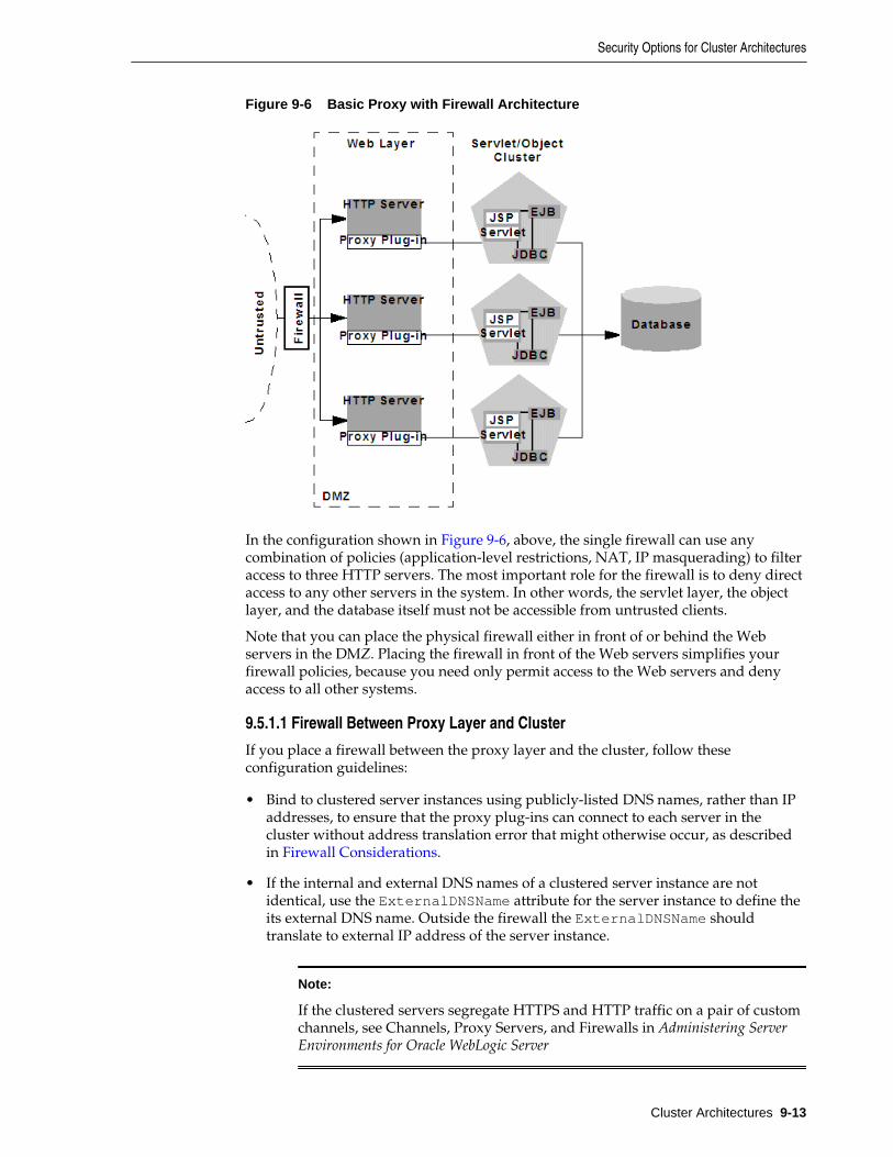
Figure 9-6 Basic Proxy with Firewall Architecture
In the configuration shown in Figure 9-6, above, the single firewall can use anycombination of policies (application-level restrictions, NAT, IP masquerading) to filteraccess to three HTTP servers. The most important role for the firewall is to deny directaccess to any other servers in the system. In other words, the servlet layer, the objectlayer, and the database itself must not be accessible from untrusted clients.
Note that you can place the physical firewall either in front of or behind the Webservers in the DMZ. Placing the firewall in front of the Web servers simplifies yourfirewall policies, because you need only permit access to the Web servers and denyaccess to all other systems.
9.5.1.1 Firewall Between Proxy Layer and Cluster
If you place a firewall between the proxy layer and the cluster, follow theseconfiguration guidelines:
• Bind to clustered server instances using publicly-listed DNS names, rather than IPaddresses, to ensure that the proxy plug-ins can connect to each server in thecluster without address translation error that might otherwise occur, as describedin Firewall Considerations.
• If the internal and external DNS names of a clustered server instance are notidentical, use the ExternalDNSName attribute for the server instance to define theits external DNS name. Outside the firewall the ExternalDNSName shouldtranslate to external IP address of the server instance.
Note:
If the clustered servers segregate HTTPS and HTTP traffic on a pair of customchannels, see Channels, Proxy Servers, and Firewalls in Administering ServerEnvironments for Oracle WebLogic Server
Security Options for Cluster Architectures
Cluster Architectures 9-13
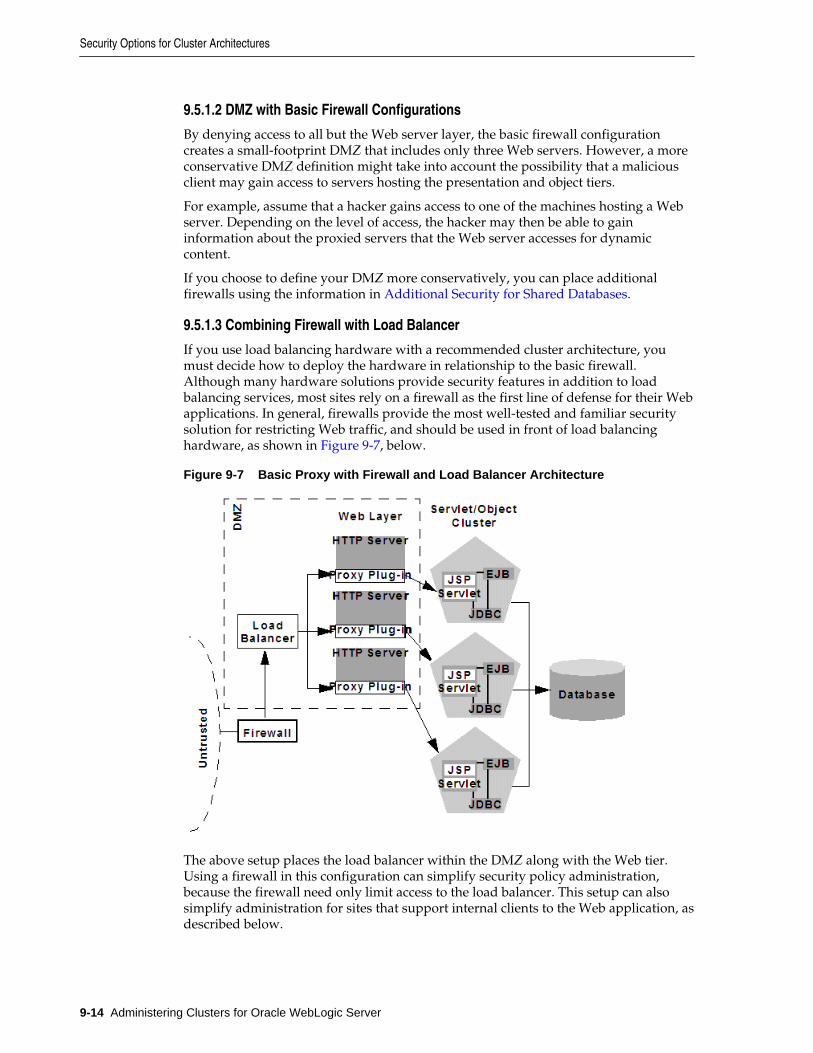
9.5.1.2 DMZ with Basic Firewall Configurations
By denying access to all but the Web server layer, the basic firewall configurationcreates a small-footprint DMZ that includes only three Web servers. However, a moreconservative DMZ definition might take into account the possibility that a maliciousclient may gain access to servers hosting the presentation and object tiers.
For example, assume that a hacker gains access to one of the machines hosting a Webserver. Depending on the level of access, the hacker may then be able to gaininformation about the proxied servers that the Web server accesses for dynamiccontent.
If you choose to define your DMZ more conservatively, you can place additionalfirewalls using the information in Additional Security for Shared Databases.
9.5.1.3 Combining Firewall with Load Balancer
If you use load balancing hardware with a recommended cluster architecture, youmust decide how to deploy the hardware in relationship to the basic firewall.Although many hardware solutions provide security features in addition to loadbalancing services, most sites rely on a firewall as the first line of defense for their Webapplications. In general, firewalls provide the most well-tested and familiar securitysolution for restricting Web traffic, and should be used in front of load balancinghardware, as shown in Figure 9-7, below.
Figure 9-7 Basic Proxy with Firewall and Load Balancer Architecture
The above setup places the load balancer within the DMZ along with the Web tier.Using a firewall in this configuration can simplify security policy administration,because the firewall need only limit access to the load balancer. This setup can alsosimplify administration for sites that support internal clients to the Web application, asdescribed below.
Security Options for Cluster Architectures
9-14 Administering Clusters for Oracle WebLogic Server
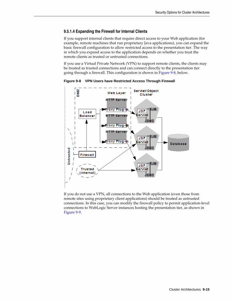
9.5.1.4 Expanding the Firewall for Internal Clients
If you support internal clients that require direct access to your Web application (forexample, remote machines that run proprietary Java applications), you can expand thebasic firewall configuration to allow restricted access to the presentation tier. The wayin which you expand access to the application depends on whether you treat theremote clients as trusted or untrusted connections.
If you use a Virtual Private Network (VPN) to support remote clients, the clients maybe treated as trusted connections and can connect directly to the presentation tiergoing through a firewall. This configuration is shown in Figure 9-8, below.
Figure 9-8 VPN Users have Restricted Access Through Firewall
If you do not use a VPN, all connections to the Web application (even those fromremote sites using proprietary client applications) should be treated as untrustedconnections. In this case, you can modify the firewall policy to permit application-levelconnections to WebLogic Server instances hosting the presentation tier, as shown in Figure 9-9.
Security Options for Cluster Architectures
Cluster Architectures 9-15
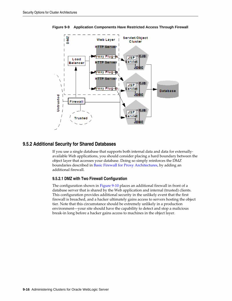
Figure 9-9 Application Components Have Restricted Access Through Firewall
9.5.2 Additional Security for Shared DatabasesIf you use a single database that supports both internal data and data for externally-available Web applications, you should consider placing a hard boundary between theobject layer that accesses your database. Doing so simply reinforces the DMZboundaries described in Basic Firewall for Proxy Architectures, by adding anadditional firewall.
9.5.2.1 DMZ with Two Firewall Configuration
The configuration shown in Figure 9-10 places an additional firewall in front of adatabase server that is shared by the Web application and internal (trusted) clients.This configuration provides additional security in the unlikely event that the firstfirewall is breached, and a hacker ultimately gains access to servers hosting the objecttier. Note that this circumstance should be extremely unlikely in a productionenvironment—your site should have the capability to detect and stop a maliciousbreak-in long before a hacker gains access to machines in the object layer.
Security Options for Cluster Architectures
9-16 Administering Clusters for Oracle WebLogic Server
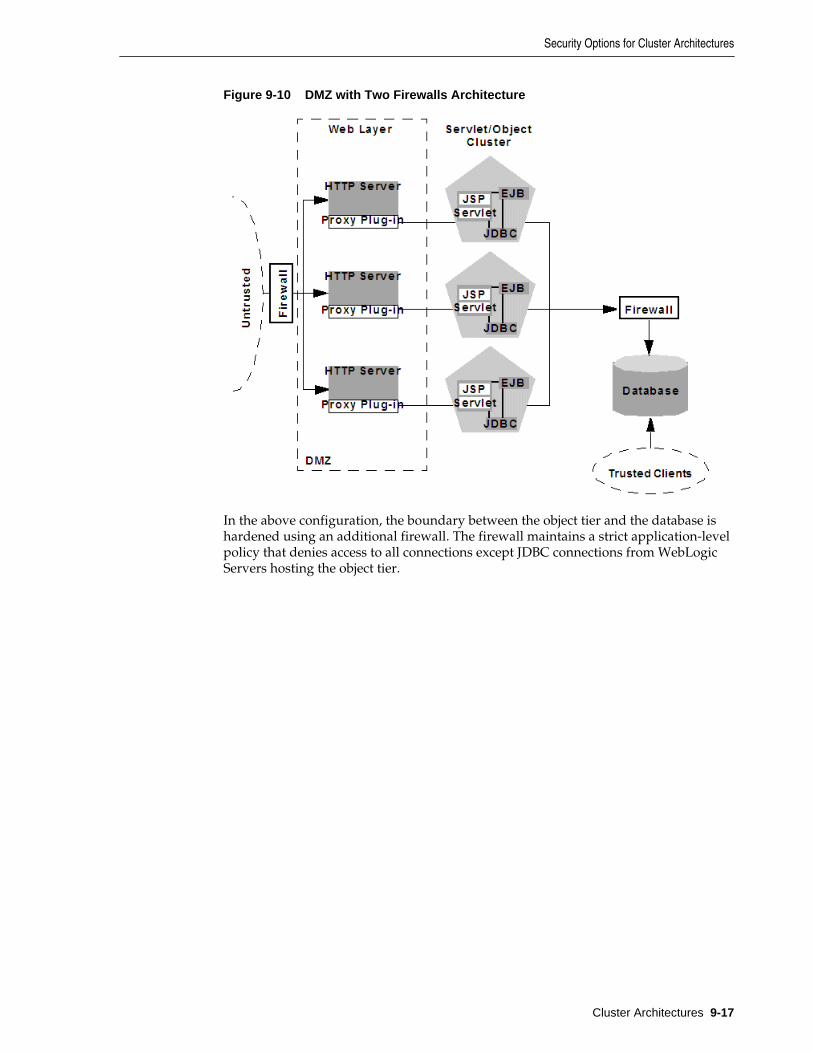
Figure 9-10 DMZ with Two Firewalls Architecture
In the above configuration, the boundary between the object tier and the database ishardened using an additional firewall. The firewall maintains a strict application-levelpolicy that denies access to all connections except JDBC connections from WebLogicServers hosting the object tier.
Security Options for Cluster Architectures
Cluster Architectures 9-17

Security Options for Cluster Architectures
9-18 Administering Clusters for Oracle WebLogic Server
10Setting up WebLogic Clusters
This chapter contains guidelines and instructions for configuring a WebLogic Servercluster.
This chapter includes the following sections:
• Before You Start
• Cluster Implementation Procedures
10.1 Before You StartThis section summarizes prerequisite tasks and information for setting up a WebLogicServer cluster.
10.1.1 Understand the Configuration ProcessThe information in this section will be most useful to you if you have a basicunderstanding of the cluster configuration process and how configuration tasks areaccomplished.
For information about the configuration facilities available in WebLogic Server and thetasks they support, see Understanding Cluster Configuration.
10.1.2 Determine Your Cluster ArchitectureDetermine what cluster architecture best suits your needs. Key architectural decisionsinclude:
• Should you combine all application tiers in a single cluster or segment yourapplication tiers in separate clusters?
• How will you balance the load among server instances in your cluster? Will you:
– Use basic WebLogic Server load balancing,
– Implement a third-party load balancer, or
– Deploy the Web tier of your application on one or more secondary HTTPservers, and proxy requests to it?
• Should you define your Web applications De-Militarized Zone (DMZ) with one ormore firewalls?
To guide these decisions, see Cluster Architectures, and Load Balancing in a Cluster.
The architecture you choose affects how you set up your cluster. The clusterarchitecture may also require that you install or configure other resources, such asload balancers, HTTP servers, and proxy plug-ins.
Setting up WebLogic Clusters 10-1
10.1.3 Consider Your Network and Security TopologiesYour security requirements form the basis for designing the appropriate securitytopology. For a discussion of several alternative architectures that provide varyinglevels of application security, see Security Options for Cluster Architectures.
Note:
Some network topologies can interfere with multicast communication. If youare deploying a cluster across a WAN, see If Your Cluster Spans MultipleSubnets In a WAN .
Avoid deploying server instances in a cluster across a firewall. For adiscussion of the impact of tunneling multicast traffic through a firewall, see Firewalls Can Break Multicast Communication.
10.1.4 Choose Machines for the Cluster InstallationIdentify the machine or machines where you plan to install WebLogic Server—throughout this section we refer to such machines as "hosts"—and ensure that theyhave the resources required. WebLogic Server allows you to set up a cluster on asingle, non-multihomed machine. This new capability is useful for demonstration ordevelopment environments.
Note:
Do not install WebLogic Server on machines that have dynamically assignedIP addresses.
10.1.4.1 WebLogic Server Instances on Multi-CPU Machines
WebLogic Server has no built-in limit for the number of server instances that canreside in a cluster. Large, multi-processor servers such as Sun Microsystems, Inc. SunEnterprise 10000 can host very large clusters or multiple clusters.
Oracle recommends that you start with one server per CPU and then scale up basedon the expected behavior. However, as with all capacity planning, you should test theactual deployment with your target Web applications to determine the optimalnumber and distribution of server instances. See Running Multiple Server Instances onMulti-Core Machines in Tuning Performance of Oracle WebLogic Server for additionalinformation.
10.1.4.2 Check Host Machines' Socket Reader Implementation
For best socket performance, configure the WebLogic Server host machine to use thenative socket reader implementation for your operating system, rather than the pure-Java implementation. To understand why, and for instructions for configuring nativesockets or optimizing pure-Java socket communications, see Peer-to-PeerCommunication Using IP Sockets.
10.1.4.3 Setting Up a Cluster on a Disconnected Windows Machine
If you want to demonstrate a WebLogic Server cluster on a single, disconnectedWindows machine, you must force Windows to load the TCP/IP stack. By default,
Before You Start
10-2 Administering Clusters for Oracle WebLogic Server
Windows does not load the TCP/IP stack if it does not detect a physical networkconnection.
To force Windows to load the TCP/IP stack, disable the Windows media sensingfeature using the instructions in How to Disable Media Sense for TCP/IP in Windowsat http://support.microsoft.com/default.aspx?scid=kb;en-us;239924.
10.1.5 Identify Names and AddressesDuring the cluster configuration process, you supply addressing information—IPaddresses or DNS names, and port numbers—for the server instances in the cluster.
For information on intra-cluster communication, and how it enables load balancingand failover, see Choosing WebLogic Server Cluster Messaging Protocols.
When you set up your cluster, you must provide location information for:
• Administration Server
• Managed Servers
• Multicast location
Read the sections that follow for an explanation of the information you must provide,and factors that influence the method you use to identify resources.
10.1.5.1 Avoiding Listen Address Problems
As you configure a cluster, you can specify address information using either IPaddresses or DNS names.
10.1.5.1.1 DNS Names or IP Addresses?
Consider the purpose of the cluster when deciding whether to use DNS names or IPaddresses. For production environments, the use of DNS names is generallyrecommended. The use of IP addresses can result in translation errors if:
• Clients will connect to the cluster through a firewall, or
• You have a firewall between the presentation and object tiers, for example, youhave a servlet cluster and EJB cluster with a firewall in between, as described in therecommended multi-tier cluster.
You can avoid translation errors by binding the address of an individual serverinstance to a DNS name. Make sure that a server instance's DNS name is identical oneach side of firewalls in your environment, and do not use a DNS name that is also thename of an NT system on your network.
For more information about using DNS names instead of IP addresses, see FirewallConsiderations.
10.1.5.1.2 When Internal and External DNS Names Vary
If the internal and external DNS names of a WebLogic Server instance are notidentical, use the ExternalDNSName attribute for the server instance to define theserver's external DNS name. Outside the firewall the ExternalDNSName shouldtranslate to external IP address of the server. If clients are accessing WebLogic Serverover the default channel and T3, do not set the ExternalDNSName attribute, even ifthe internal and external DNS names of a WebLogic Server instance are not identical.
Before You Start
Setting up WebLogic Clusters 10-3
10.1.5.1.3 Localhost Considerations
If you identify a server instance's listen address as localhost, non-local processes willnot be able to connect to the server instance. Only processes on the machine that hoststhe server instance will be able to connect to the server instance. If the server instancemust be accessible as localhost (for instance, if you have administrative scripts thatconnect to localhost), and must also be accessible by remote processes, leave the listenaddress blank. The server instance will determine the address of the machine andlisten on it.
10.1.5.2 Assigning Names to WebLogic Server Resources
Make sure that each configurable resource in your WebLogic Server environment hasa unique name. Each, domain, server, machine, cluster, data source, virtual host, orother resource must have a unique name.
10.1.5.3 Administration Server Address and Port
Identify the DNS name or IP address and listen port of the Administration Server youwill use for the cluster.
The Administration Server is the WebLogic Server instance used to configure andmanage all the Managed Servers in its domain. When you start a Managed Server, youidentify the host and port of its Administration Server.
10.1.5.4 Managed Server Addresses and Listen Ports
Identify the DNS name or IP address of each Managed Server planned for yourcluster.
Each Managed Server in a cluster must have a unique combination of address andlisten port number. Clustered server instances on a single non-multihomed machinecan have the same address, but must use a different listen port.
10.1.5.5 Cluster Multicast Address and Port
Identify the address and port you will dedicate to multicast communications for yourcluster. A multicast address is an IP address between 224.0.0.0 and 239.255.255.255.
Note:
The default multicast value used by WebLogic Server is 239.192.0.0. Youshould not use any multicast address with the value x.0.0.1.
Server instances in a cluster communicate with each other using multicast—they usemulticast to announce their services, and to issue periodic heartbeats that indicatecontinued availability.
The multicast address for a cluster should not be used for any purpose other thancluster communications. If the machine where the cluster multicast address existshosts or is accessed by cluster-external programs that use multicast communication,make sure that those multicast communications use a different port than the clustermulticast port.
10.1.5.5.1 Multicast and Multiple Clusters
Multiple clusters on a network may share a multicast address and multicast portcombination if necessary.
Before You Start
10-4 Administering Clusters for Oracle WebLogic Server
10.1.5.5.2 Multicast and Multi-Tier Clusters
If you are setting up the Recommended Multi-Tier Architecture, described in ClusterArchitectures, with a firewall between the clusters, you will need two dedicatedmulticast addresses: one for the presentation (servlet) cluster and one for the objectcluster. Using two multicast addresses ensures that the firewall does not interfere withcluster communication.
10.1.5.6 Cluster Address
In WebLogic Server cluster, the cluster address is used in entity and stateless beans toconstruct the host name portion of request URLs.
You can explicitly define the cluster address when you configure the a cluster;otherwise, WebLogic Server dynamically generates the cluster address for each newrequest. Allowing WebLogic Server to dynamically generate the cluster address issimplest, in terms of system administration, and is suitable for both development andproduction environments.
10.1.5.6.1 Dynamic Cluster Address
If you do not explicitly define a cluster address when you configure a cluster, when aclustered server instance receives a remote request, WebLogic Server generates thecluster address, in the form:
listenaddress1:listenport1,listenaddress2:listenport2;listenaddress3:listenport3
Each listen address:listen port combination in the cluster addresscorresponds to Managed Server and network channel that received the request.
• If the request was received on the Managed Server's default channel, the listenaddress:listen port combinations in the cluster address reflect theListenAddress and ListenPort values from the associated ServerMBean andSSLMBean instances. For more information, see The Default Network Channel inAdministering Server Environments for Oracle WebLogic Server.
• If the request was received on a custom network channel, the listenaddress:listen port in the cluster address reflect the ListenAddress andListenPort values from NetworkAccessPointMBean that defines the channel.For more information about network channels in a cluster, see ConfiguringNetwork Channels For a Cluster in Administering Server Environments for OracleWebLogic Server.
The number of ListenAddress:ListenPort combinations included in the clusteraddress is governed by the value of the NumberOfServersInClusterAddressattribute on the ClusterMBean, which is 3 by default.
Before You Start
Setting up WebLogic Clusters 10-5
Note:
You can set NumberOfServersInClusterAddress attribute to a minimumvalue of 1. This attribute is used when WebLogic Server dynamicallyconstructs cluster address for use with EJBs. In WebLogic Server cluster, thecluster address is used in entity and stateless beans to construct the host nameportion of requested URLs. You can explicitly define the cluster address whileconfiguring a cluster. Otherwise, WebLogic Server dynamically generates thecluster address for each new request. Allowing WebLogic Server todynamically generate the cluster address is the simplest and convenientmethod for System Administration, and both development and productionenvironments.
You can modify the value of NumberOfServersInClusterAddress on theEnvironments > Clusters > ClusterName > Configuration > General page of theWebLogic Server Administration Console.
• If there are fewer Managed Servers available in the cluster than the value ofNumberOfServersInClusterAddress, the dynamically generated clusteraddress contains a ListenAddress:ListenPort combination for each of therunning Managed Servers.
• If there are more Managed Servers available in the cluster than the value ofNumberOfServersInClusterAddress, WebLogic Server randomly selects asubset of the available instances—equal to the value ofNumberOfServersInClusterAddress—and uses theListenAddress:ListenPort combination for those instances to form thecluster address.
The order in which the ListenAddress:ListenPort combinations appear in thecluster address is random—from request to request, the order will vary.
10.1.5.6.2 Explicitly Defining Cluster Address for Production Environments
If you explicitly define a cluster address for a cluster in a production environment,specify the cluster address as a DNS name that maps to the IP addresses or DNSnames of each WebLogic Server instance in the cluster.
If you define the cluster address as a DNS name, the listen ports for the clustermembers are not specified in the cluster address—it is assumed that each ManagedServer in the cluster has the same listen port number. Because each server instance in acluster must have a unique combination of address and listen port, if a cluster addressis a DNS name, each server instance in the cluster must have:
• a unique address and
• the same listen port number
When clients obtain an initial JNDI context by supplying the cluster DNS name,weblogic.jndi.WLInitialContextFactory obtains the list of all addresses thatare mapped to the DNS name. This list is cached by WebLogic Server instances, andnew initial context requests are fulfilled using addresses in the cached list with around-robin algorithm. If a server instance in the cached list is unavailable, it isremoved from the list. The address list is refreshed from the DNS service only if theserver instance is unable to reach any address in its cache.
Before You Start
10-6 Administering Clusters for Oracle WebLogic Server
Using a cached list of addresses avoids certain problems with relying on DNS round-robin alone. For example, DNS round-robin continues using all addresses that havebeen mapped to the domain name, regardless of whether or not the addresses arereachable. By caching the address list, WebLogic Server can remove addresses that areunreachable, so that connection failures aren't repeated with new initial contextrequests.
Note:
The Administration Server should not participate in a cluster. Ensure that theAdministration Server's IP address is not included in the cluster-wide DNSname. For more information, see Administration Server Considerations.
10.1.5.6.3 Explicitly Defining Cluster Address for Development and Test Environments
If you explicitly define a cluster address for use in development environments, youcan use a cluster DNS name for the cluster address, as described in the previoussection.
Alternatively, you can define the cluster address as a list that contains the DNS name(or IP address) and listen port of each Managed Server in the cluster, as shown in theexamples below:
DNSName1:port1,DNSName1:port2,DNSName1:port3IPaddress1:port1,IPaddress2:port2;IPaddress3:port3
Note that each cluster member has a unique address and port combination.
10.1.5.6.4 Explicitly Defining Cluster Address for Single, Multihomed Machine
If your cluster runs on a single, multihomed machine, and each server instance in thecluster uses a different IP address, define the cluster address using a DNS name thatmaps to the IP addresses of the server instances in the cluster. If you define the clusteraddress as a DNS name, specify the same listen port number for each of the ManagedServers in the cluster.
10.2 Cluster Implementation ProceduresThis section describes how to get a clustered application up and running, frominstallation of WebLogic Server through initial deployment of applicationcomponents.
10.2.1 Configuration RoadmapThis section lists typical cluster implementation tasks, and highlights keyconfiguration considerations. The exact process you follow is driven by the uniquecharacteristics of your environment and the nature of your application. These tasks aredescribed:
1. Install WebLogic Server
Create a Clustered Domain
2. Configure Node Manager
3. Configure Load Balancing Method for EJBs and RMIs
4. Configure Server Affinity for Distributed JMS Destinations
Cluster Implementation Procedures
Setting up WebLogic Clusters 10-7
5. Configuring Load Balancers that Support Passive Cookie Persistence
6. Configure Proxy Plug-Ins
7. Configure Replication Groups
8. Configure Migratable Targets for Pinned Services
9. Package Applications for Deployment
10. Deploy Applications
11. Deploying_ Activating_ and Migrating Migratable Services
12. Configure In-Memory HTTP Replication
13. Additional Configuration Topics
Not every step is required for every cluster implementation. Additional steps may benecessary in some cases.
10.2.2 Install WebLogic ServerIf you have not already done so, install WebLogic Server. For instructions, see Planning the Oracle WebLogic Server Installation in Installing and Configuring OracleWebLogic Server and Coherence.
• If the cluster will run on a single machine, do a single installation of WebLogicServer under the /Oracle directory to use for all clustered instances.
• For remote, networked machines, install the same version of WebLogic Server oneach machine. Each machine:
– Must have permanently assigned, static IP addresses. You cannot usedynamically-assigned IP addresses in a clustering environment.
– Must be accessible to clients. If the server instances are behind a firewall and theclients are in front of the firewall, each server instance must have a public IPaddress that can be reached by the clients.
– Must be located on the same local area network (LAN) and must be reachablevia IP multicast.
10.2.3 Create a Clustered DomainThe are multiple methods of creating a clustered domain. For a list, see Methods ofConfiguring Clusters.
For instructions to create a cluster using the:
• Configuration Wizard, first see Creating a WebLogic Domain in Creating WebLogicDomains Using the Configuration Wizard for instructions on creating the domain, andthen Clusters for instructions on configuring a cluster.
• WebLogic Server Administration Console, see Create and configure clusters inOracle WebLogic Server Administration Console Online Help.
Cluster Implementation Procedures
10-8 Administering Clusters for Oracle WebLogic Server
10.2.3.1 Starting a WebLogic Server Cluster
There are multiple methods of starting a cluster—available options include thecommand-line interface, scripts that contain the necessary commands, and NodeManager.
Note:
Node Manager eases the process of starting servers, and restarting them afterfailure.
To use Node Manager, you must first configure a Node Manager process oneach machine that hosts Managed Servers in the cluster. See Configure NodeManager.
Regardless of the method you use to start a cluster, start the Administration Serverfirst, then start the Managed Servers in the cluster.
Follow the instructions below to start the cluster from a command shell. Note thateach server instance is started in a separate command shell.
1. Open a command shell.
2. Change directory to the domain directory that you created with the ConfigurationWizard.
3. Type this command to start the Administration Server:
StartWebLogic
4. Enter the user name for the domain at the "Enter username to boot WebLogicServer" prompt.
5. Enter the password for the domain at the "Enter password to boot WebLogicServer" prompt.
The command shell displays messages that report the status of the startup process.
6. Open another command shell so that you can start a Managed Server.
7. Change directory to the domain directory that you created with the ConfigurationWizard.
8. Type this command
StartManagedWebLogic server_name address:port
where:
server_name is the name of the Managed Server you wish to start
address is the IP address or DNS name for the Administration Server for the domain
port is the listen port for the Administration Server for the domain
9. Enter the user name for the domain at the "Enter username to boot WebLogicServer" prompt.
Cluster Implementation Procedures
Setting up WebLogic Clusters 10-9
10. Enter the password for the domain at the "Enter password to boot WebLogicServer" prompt.
The command shell displays messages that report the status of the startup process.
Note:
After you start a Managed Server, it listens for heartbeats from other runningserver instances in the cluster. The Managed Server builds its local copy of thecluster-wide JNDI tree, as described in How WebLogic Server Updates theJNDI Tree, and displays status messages when it has synchronized with eachrunning Managed Server in the cluster. The synchronization process can takea minute or so.
11. To start another server instance in the cluster, return to step 6. Continue throughstep 10.
12. When you have started all Managed Servers in the cluster, the cluster startupprocess is complete.
10.2.4 Configure Node ManagerNode Manager is a standalone program provided with WebLogic Server that is usefulfor starting a Managed Server that resides on a different machine than itsAdministration Server. Node Manager also provides features that help increase theavailability of Managed Servers in your cluster. For more information, and forinstructions to configure and use Node Manager, see Administering Node Manager forOracle WebLogic Server.
10.2.5 Configure Load Balancing Method for EJBs and RMIsFollow the instructions in this section to select the load balancing algorithm for EJBsand RMI objects.
Unless you explicitly specify otherwise, WebLogic Server uses the round-robinalgorithm as the default load balancing strategy for clustered object stubs. Tounderstand alternative load balancing algorithms, see Load Balancing for EJBs andRMI Objects. To change the default load balancing algorithm:
1. Open the WebLogic Server Administration Console.
2. Select Environments > Clusters.
3. Select the name of your cluster in the table.
4. If you have not already done so, click Lock & Edit in the top left corner of theConsole.
5. Enter the desired load balancing algorithm in the Default Load Algorithmfield.
6. Select Advanced.
7. Enter the desired value in the Service Age Threshold field
8. Click Save to save your changes.
Cluster Implementation Procedures
10-10 Administering Clusters for Oracle WebLogic Server
9. Click Activate Changes in the top left corner once you are ready to activate yourchanges.
10.2.6 Specifying a Timeout Value For RMIsYou can enable a timeout option when making calls to the ReplicationManager bysetting the ReplicationTimeoutEnabled in the ClusterMBean to true.
The timeout value is equal to the multicast heartbeat timeout. Although you cancustomize the multicast timeout value, the ReplicationManager timeout cannot bechanged. This restriction exists because the ReplicationManager timeout does notaffect cluster membership. A missing multicast heartbeat causes the member to beremoved from the cluster and the timed out ReplicationManager call will choose anew secondary server to connect to.
Note:
It is possible that a cluster member will continue to send multicast heartbeats,but will be unable to process replication requests. This could potentially causean uneven distribution of secondary servers. When this situation occurs, awarning message is recorded in the server logs.
10.2.7 Configure Server Affinity for Distributed JMS DestinationsTo understand the server affinity support provided by WebLogic Server for JMS, see Load Balancing for JMS.
10.2.8 Configuring Load Balancers that Support Passive Cookie PersistenceLoad balancers that support passive cookie persistence can use information from theWebLogic Server session cookie to associate a client with the WebLogic Serverinstance that hosts the session. The session cookie contains a string that the loadbalancer uses to identify the primary server instance for the session.
For a discussion of external load balancers, session cookie persistence, and theWebLogic Server session cookie, see Load Balancing HTTP Sessions with an ExternalLoad Balancer.
To configure the load balancer to work with your cluster, use the facilities of the loadbalancer to define the offset and length of the string constant.
Assuming that the Session ID portion of the session cookie is the default length of 52bytes, on the load balancer, set:
• string offset to 53 bytes, the default Random Session ID length plus 1 byte for thedelimiter character.
• string length to 10 bytes
If your application or environmental requirements dictate that you change the lengthof the Random Session ID from its default value of 52 bytes, set the string offset on theload balancer accordingly. The string offset must equal the length of the Session IDplus 1 byte for the delimiter character.
Cluster Implementation Procedures
Setting up WebLogic Clusters 10-11
Note:
For vendor-specific instructions for configuring Big-IP load balancers, see Configuring BIG-IP Hardware with Clusters.
10.2.9 Configure Proxy Plug-InsRefer to the instructions in this section if you wish to load balance servlets and JSPsusing a proxy plug-in. A proxy plug-in proxies requests from a Web server toWebLogic Server instances in a cluster, and provides load balancing and failover forthe proxied HTTP requests.
For information about load balancing using proxy plug-ins, see Load Balancing with aProxy Plug-in. For information about connection and failover using proxy plug-ins,see Replication and Failover for Servlets and JSPs , and Accessing Clustered Servletsand JSPs Using a Proxy.
• If you use WebLogic Server as a Web server, set up HttpClusterServlet usingthe instructions in Set Up the HttpClusterServlet.
• If you use a supported third-party Web server, set up a product-specific plug-in(for a list of supported Web servers, see Load Balancing with a Proxy Plug-in)follow the instructions in Using Oracle WebLogic Server Proxy Plug-Ins.
Note:
Each Web server that proxies requests to a cluster must have an identicallyconfigured plug-in.
10.2.9.1 Set Up the HttpClusterServlet
To use the HTTP cluster servlet, configure it as the default Web application on yourproxy server machine, as described in the steps below. For an introduction to Webapplications, see Understanding Web Applications, Servlets, and JSPs in DevelopingWeb Applications, Servlets, and JSPs for Oracle WebLogic Server.
1. If you have not already done so, configure a separate, non-clustered ManagedServer to host the HTTP Cluster Servlet.
2. Create the web.xml deployment descriptor file for the servlet. This file mustreside in the \WEB-INF subdirectory of the Web application directory. A sampledeployment descriptor for the proxy servlet is provided in Sample web.xml. Formore information on web.xml, see Understanding Web Applications, Servlets,and JSPs in Developing Web Applications, Servlets, and JSPs for Oracle WebLogicServer.
a. Define the name and class for the servlet in the <servlet> element inweb.xml. The servlet name is HttpClusterServlet. The servlet class isweblogic.servlet.proxy.HttpClusterServlet.
b. Identify the clustered server instances to which the proxy servlet will directrequests in the <servlet> element in web.xml, by defining theWebLogicCluster parameter.
Cluster Implementation Procedures
10-12 Administering Clusters for Oracle WebLogic Server
c. Optionally, define the following <KeyStore> initialization parameters to usetwo-way SSL with your own identity certificate and key. If no <KeyStore> isspecified in the deployment descriptor, the proxy will assume one-way SSL.
• <KeyStore>—The key store location in your Web application.
• <KeyStoreType>—The key store type. If it is not defined, the defaulttype will be used instead.
• <PrivateKeyAlias>—The private key alias.
• <KeyStorePasswordProperties>—A property file in your Webapplication that defines encrypted passwords to access the key store andprivate key alias. The file contents looks like this:
KeyStorePassword={AES}yWv/i0qhfM4/IvzoghzjHj/xpJUkQPF8OWuSfh0f0Ss=PrivateKeyPassword={AES}wr86u9Z5DHr+5p7WIbzTDSy4M/sl7EYnX/K5xzcarDQ=
You must use the weblogic.security.Encrypt command-line utility toencrypt the password. For more information on the Encrypt utility, aswell as the CertGen, and der2pem utilities, see Using the Oracle WebLogicServer Java Utilities in the Command Reference for Oracle WebLogic Server.
d. Create <servlet-mapping> stanzas to specify the requests that the servletwill proxy to the cluster, using the <url-pattern> element to identifyspecific file extensions, for example *.jsp, or *.html. Define each pattern ina separate <servlet-mapping> stanza.
You can set the <url-pattern> to "/" to proxy any request that cannot beresolved by WebLogic Server to the remote server instance. If you do so, youmust also specifically map the following extensions: *.jsp, *.html, and*.html, to proxy files ending with those extensions. For an example, see Sample web.xml.
e. You can enable the WLProxyPassThrough attribute to allow the header tobe passed through a chain of proxies and the WLProxySSLPassThroughattribute so that the use of SSL is passed on to WebLogic Server. For acomplete description of these attributes, see General Parameters for WebServer Plug-Ins in Using Oracle WebLogic Server Proxy Plug-Ins.
f. Define, as appropriate, any additional parameters. See Table 10-1 for a list ofkey parameters. See Parameters for Web Server Plug-ins in Using OracleWebLogic Server Proxy Plug-Ins for a complete list. Follow the syntaxinstructions in Proxy Servlet Deployment Parameters.
3. Create the weblogic.xml deployment descriptor file for the servlet. This filemust reside in the \WEB-INF subdirectory of the Web application directory.
Assign the proxy servlet as the default Web application for the Managed Serveron the proxy machine by setting the <context-root> element to a forwardslash character (/) in the <weblogic-web-app> stanza. For an example, see Sample weblogic.xml.
4. In the WebLogic Server Administration Console, deploy the servlet to theManaged Server on your proxy server machine. For instructions, see Deployapplications and modules in Oracle WebLogic Server Administration Console OnlineHelp.
Cluster Implementation Procedures
Setting up WebLogic Clusters 10-13
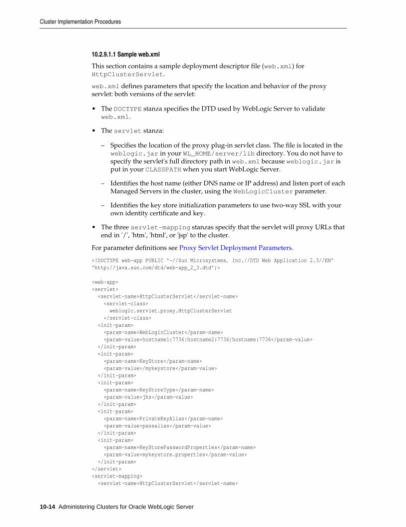
10.2.9.1.1 Sample web.xml
This section contains a sample deployment descriptor file (web.xml) forHttpClusterServlet.
web.xml defines parameters that specify the location and behavior of the proxyservlet: both versions of the servlet:
• The DOCTYPE stanza specifies the DTD used by WebLogic Server to validateweb.xml.
• The servlet stanza:
– Specifies the location of the proxy plug-in servlet class. The file is located in theweblogic.jar in your WL_HOME/server/lib directory. You do not have tospecify the servlet's full directory path in web.xml because weblogic.jar isput in your CLASSPATH when you start WebLogic Server.
– Identifies the host name (either DNS name or IP address) and listen port of eachManaged Servers in the cluster, using the WebLogicCluster parameter.
– Identifies the key store initialization parameters to use two-way SSL with yourown identity certificate and key.
• The three servlet-mapping stanzas specify that the servlet will proxy URLs thatend in '/', 'htm', 'html', or 'jsp' to the cluster.
For parameter definitions see Proxy Servlet Deployment Parameters.
<!DOCTYPE web-app PUBLIC "-//Sun Microsystems, Inc.//DTD Web Application 2.3//EN" "http://java.sun.com/dtd/web-app_2_3.dtd";>
<web-app><servlet> <servlet-name>HttpClusterServlet</servlet-name> <servlet-class> weblogic.servlet.proxy.HttpClusterServlet </servlet-class> <init-param> <param-name>WebLogicCluster</param-name> <param-value>hostname1:7736|hostname2:7736|hostname:7736</param-value> </init-param> <init-param> <param-name>KeyStore</param-name> <param-value>/mykeystore</param-value> </init-param> <init-param> <param-name>KeyStoreType</param-name> <param-value>jks</param-value> </init-param> <init-param> <param-name>PrivateKeyAlias</param-name> <param-value>passalias</param-value> </init-param> <init-param> <param-name>KeyStorePasswordProperties</param-name> <param-value>mykeystore.properties</param-value> </init-param></servlet><servlet-mapping> <servlet-name>HttpClusterServlet</servlet-name>
Cluster Implementation Procedures
10-14 Administering Clusters for Oracle WebLogic Server
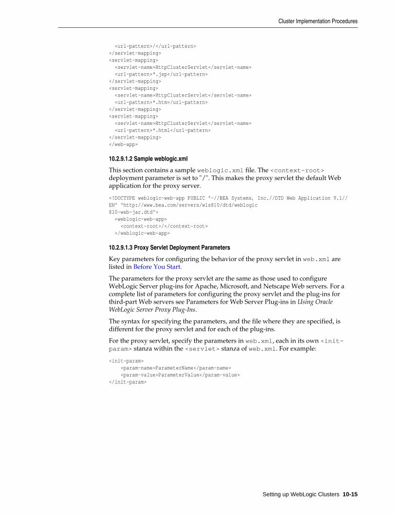
<url-pattern>/</url-pattern></servlet-mapping><servlet-mapping> <servlet-name>HttpClusterServlet</servlet-name> <url-pattern>*.jsp</url-pattern> </servlet-mapping> <servlet-mapping> <servlet-name>HttpClusterServlet</servlet-name> <url-pattern>*.htm</url-pattern> </servlet-mapping><servlet-mapping> <servlet-name>HttpClusterServlet</servlet-name> <url-pattern>*.html</url-pattern> </servlet-mapping></web-app>
10.2.9.1.2 Sample weblogic.xml
This section contains a sample weblogic.xml file. The <context-root>deployment parameter is set to "/". This makes the proxy servlet the default Webapplication for the proxy server.
<!DOCTYPE weblogic-web-app PUBLIC "-//BEA Systems, Inc.//DTD Web Application 9.1//EN" "http://www.bea.com/servers/wls810/dtd/weblogic810-web-jar.dtd"> <weblogic-web-app> <context-root>/</context-root> </weblogic-web-app>
10.2.9.1.3 Proxy Servlet Deployment Parameters
Key parameters for configuring the behavior of the proxy servlet in web.xml arelisted in Before You Start.
The parameters for the proxy servlet are the same as those used to configureWebLogic Server plug-ins for Apache, Microsoft, and Netscape Web servers. For acomplete list of parameters for configuring the proxy servlet and the plug-ins forthird-part Web servers see Parameters for Web Server Plug-ins in Using OracleWebLogic Server Proxy Plug-Ins.
The syntax for specifying the parameters, and the file where they are specified, isdifferent for the proxy servlet and for each of the plug-ins.
For the proxy servlet, specify the parameters in web.xml, each in its own <init-param> stanza within the <servlet> stanza of web.xml. For example:
<init-param> <param-name>ParameterName</param-name> <param-value>ParameterValue</param-value> </init-param>
Cluster Implementation Procedures
Setting up WebLogic Clusters 10-15
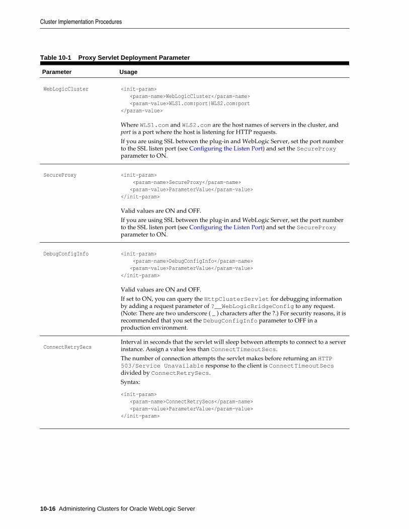
Table 10-1 Proxy Servlet Deployment Parameter
Parameter Usage
WebLogicCluster <init-param> <param-name>WebLogicCluster</param-name> <param-value>WLS1.com:port|WLS2.com:port</param-value>
Where WLS1.com and WLS2.com are the host names of servers in the cluster, andport is a port where the host is listening for HTTP requests.
If you are using SSL between the plug-in and WebLogic Server, set the port numberto the SSL listen port (see Configuring the Listen Port) and set the SecureProxyparameter to ON.
SecureProxy <init-param> <param-name>SecureProxy</param-name> <param-value>ParameterValue</param-value> </init-param>
Valid values are ON and OFF.
If you are using SSL between the plug-in and WebLogic Server, set the port numberto the SSL listen port (see Configuring the Listen Port) and set the SecureProxyparameter to ON.
DebugConfigInfo <init-param> <param-name>DebugConfigInfo</param-name> <param-value>ParameterValue</param-value> </init-param>
Valid values are ON and OFF.
If set to ON, you can query the HttpClusterServlet for debugging informationby adding a request parameter of ?__WebLogicBridgeConfig to any request.(Note: There are two underscore ( _ ) characters after the ?.) For security reasons, it isrecommended that you set the DebugConfigInfo parameter to OFF in aproduction environment.
ConnectRetrySecs Interval in seconds that the servlet will sleep between attempts to connect to a serverinstance. Assign a value less than ConnectTimeoutSecs.
The number of connection attempts the servlet makes before returning an HTTP503/Service Unavailable response to the client is ConnectTimeoutSecsdivided by ConnectRetrySecs.
Syntax:
<init-param> <param-name>ConnectRetrySecs</param-name> <param-value>ParameterValue</param-value> </init-param>
Cluster Implementation Procedures
10-16 Administering Clusters for Oracle WebLogic Server
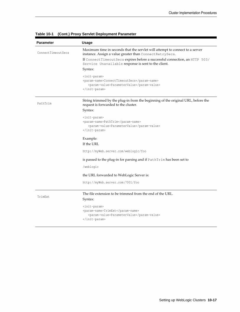
Table 10-1 (Cont.) Proxy Servlet Deployment Parameter
Parameter Usage
ConnectTimeoutSecs Maximum time in seconds that the servlet will attempt to connect to a serverinstance. Assign a value greater than ConnectRetrySecs.
If ConnectTimeoutSecs expires before a successful connection, an HTTP 503/Service Unavailable response is sent to the client.
Syntax:
<init-param><param-name>ConnectTimeoutSecs</param-name> <param-value>ParameterValue</param-value> </init-param>
PathTrim String trimmed by the plug-in from the beginning of the original URL, before therequest is forwarded to the cluster.
Syntax:
<init-param><param-name>PathTrim</param-name> <param-value>ParameterValue</param-value> </init-param>
Example:
If the URL
http://myWeb.server.com/weblogic/foo
is passed to the plug-in for parsing and if PathTrim has been set to
/weblogic
the URL forwarded to WebLogic Server is:
http://myWeb.server.com:7001/foo
TrimExt The file extension to be trimmed from the end of the URL.
Syntax:
<init-param><param-name>TrimExt</param-name> <param-value>ParameterValue</param-value> </init-param>
Cluster Implementation Procedures
Setting up WebLogic Clusters 10-17
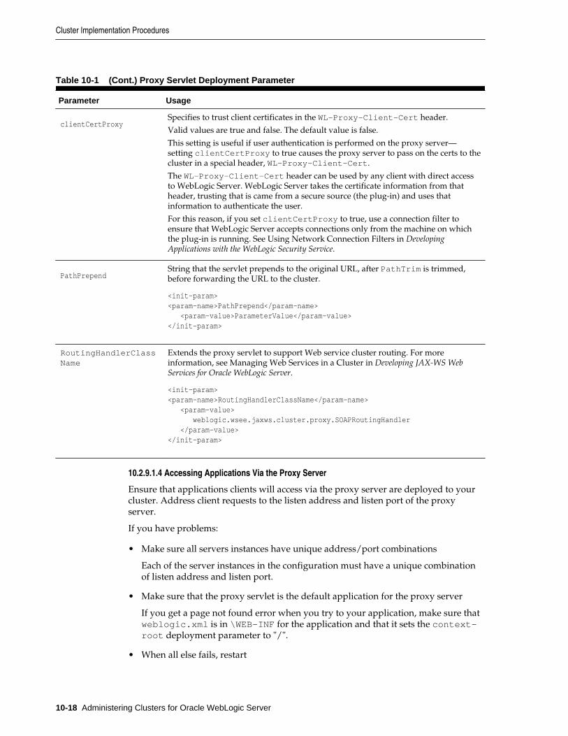
Table 10-1 (Cont.) Proxy Servlet Deployment Parameter
Parameter Usage
clientCertProxy Specifies to trust client certificates in the WL-Proxy-Client-Cert header.
Valid values are true and false. The default value is false.
This setting is useful if user authentication is performed on the proxy server—setting clientCertProxy to true causes the proxy server to pass on the certs to thecluster in a special header, WL-Proxy-Client-Cert.
The WL-Proxy-Client-Cert header can be used by any client with direct accessto WebLogic Server. WebLogic Server takes the certificate information from thatheader, trusting that is came from a secure source (the plug-in) and uses thatinformation to authenticate the user.
For this reason, if you set clientCertProxy to true, use a connection filter toensure that WebLogic Server accepts connections only from the machine on whichthe plug-in is running. See Using Network Connection Filters in DevelopingApplications with the WebLogic Security Service.
PathPrepend String that the servlet prepends to the original URL, after PathTrim is trimmed,before forwarding the URL to the cluster.
<init-param><param-name>PathPrepend</param-name> <param-value>ParameterValue</param-value> </init-param>
RoutingHandlerClassName
Extends the proxy servlet to support Web service cluster routing. For moreinformation, see Managing Web Services in a Cluster in Developing JAX-WS WebServices for Oracle WebLogic Server.
<init-param><param-name>RoutingHandlerClassName</param-name> <param-value> weblogic.wsee.jaxws.cluster.proxy.SOAPRoutingHandler </param-value> </init-param>
10.2.9.1.4 Accessing Applications Via the Proxy Server
Ensure that applications clients will access via the proxy server are deployed to yourcluster. Address client requests to the listen address and listen port of the proxyserver.
If you have problems:
• Make sure all servers instances have unique address/port combinations
Each of the server instances in the configuration must have a unique combinationof listen address and listen port.
• Make sure that the proxy servlet is the default application for the proxy server
If you get a page not found error when you try to your application, make sure thatweblogic.xml is in \WEB-INF for the application and that it sets the context-root deployment parameter to "/".
• When all else fails, restart
Cluster Implementation Procedures
10-18 Administering Clusters for Oracle WebLogic Server
If you are having problems try rebooting all your servers, some of the changes youmade while configuring your setup may not have been persisted to theconfiguration file.
• Verify Your Configuration
To verify the configuration of the HttpClusterServlet:
1. Set the DebugConfigInfo parameter in web.xml to ON.
2. Use a Web browser to access the following URL:
http://myServer:port/placeholder.jsp?__WebLogicBridgeConfig
Where:
myServer is the Managed Server on the proxy machine whereHttpClusterServlet runs, port is the port number on that server that islistening for HTTP requests, and placeholder.jsp is a file that does not exist onthe server.
The plug-in gathers configuration information and run-time statistics and returnsthe information to the browser. For more information, see Parameters for WebServer Plug-ins in Using Oracle WebLogic Server Proxy Plug-Ins.
10.2.10 Configure Replication GroupsTo support automatic failover for servlets and JSPs, WebLogic Server replicates HTTPsession states in memory. You can further control where secondary states are placedusing replication groups. A replication group is a preferred list of clustered instances tobe used for storing session state replicas.
If your cluster will host servlets or stateful session EJBs, you may want to createreplication groups of WebLogic Server instances to host the session state replicas.
For instructions on how to determine which server instances should participate ineach replication group, and to determine each server instance's preferred replicationgroup, follow the instructions in Using Replication Groups.
Then follow these steps to configure replication groups for each WebLogic Serverinstance:
To configure replication groups for a WebLogic Server instance:
1. Open the WebLogic Server Administration Console.
2. Select Environments > Servers.
3. In the table, select the name of the server you want to configure.
4. Select the Cluster page.
5. If you have not already done so, click Lock & Edit in the top left corner of theConsole.
6. Enter values for the following attribute fields:
• Replication Group: Enter the name of the replication group to which thisserver instance belongs.
• Preferred Secondary Group: Enter the name of the replication group youwould like to use to host replicated HTTP session states for this server instance.
Cluster Implementation Procedures
Setting up WebLogic Clusters 10-19
7. Click Save to save your changes.
8. Click Activate Changes in the top left corner to activate your changes.
10.2.11 Configure Migratable Targets for Pinned ServicesWebLogic Server enables you to configure an optional migratable target, which is aspecial target that can migrate from one server in a cluster to another. As such, amigratable target provides a way to group pinned services that should move together.When the migratable target is migrated, all services hosted by that target are migrated.Pinned services include JMS-related services (for example, JMS servers, SAF agents,path services, and persistent stores) or the JTA Transaction Recovery Service.
If you want to use a migratable target, configure the target server list before deployingor activating the service in the cluster. If you do not configure a migratable target inthe cluster, migratable services can be migrated to any available WebLogic Serverinstance in the cluster. For more details on migratable targets, see UnderstandingMigratable Targets In a Cluster.
10.2.12 Package Applications for DeploymentYou must package applications before you deploy them to WebLogic Server. For moreinformation, see the packaging topic in Deploying and Packaging from a SplitDevelopment Directory in Developing Applications for Oracle WebLogic Server.
10.2.13 Deploy ApplicationsClustered objects in WebLogic Server should be deployed homogeneously. To ensurehomogeneous deployment, when you select a target, use the cluster name rather thanindividual WebLogic Server instances in the cluster. If cluster is dynamic or mixedcluster type, you can select singleton or distributed deployment based on your needfor one single instance across entire cluster or one instance per cluster member.
The Console automates deploying replica-aware objects to clusters. When you deployan application or object to a cluster, the Console automatically deploys it to allmembers of the cluster (whether they are local to the Administration Server machineor they reside on remote machines.) For a discussion of application deployment inclustered environments see Methods of Configuring Clusters. For a broad discussionof deployment topics, see Deploying Applications to Oracle WebLogic Server.
Note:
All server instances in your cluster should be running when you deployapplications to the cluster using the WebLogic Server Administration Console.
10.2.13.1 Deploying to a Single Server Instance (Pinned Deployment)
Deploying a application to a server instance, rather than the all cluster members iscalled a pinned deployment. Although a pinned deployment targets a specific serverinstance, all server instances in the cluster must be running during the deploymentprocess.
You can perform a pinned deployment using the WebLogic Server AdministrationConsole or from the command line, using weblogic.Deployer.
Cluster Implementation Procedures
10-20 Administering Clusters for Oracle WebLogic Server
10.2.13.1.1 Pinned Deployment from the Command Line
From a command shell, use the following syntax to target a server instance:
java weblogic.Deployer -activate -name ArchivedEarJar -source C:/MyApps/JarEar.ear -target server1
10.2.13.2 Cancelling Cluster Deployments
You can cancel a deployment using the WebLogic Server Administration Console orfrom the command line, using weblogic.Deployer.
10.2.13.2.1 Cancel Deployment from the Command Line
From a command shell, use the following syntax to cancel the deployment task ID:
java weblogic.Deployer -adminurl http://admin:7001 -cancel -id tag
10.2.13.2.2 Cancel Deployment Using the WebLogic Server Administration Console
In the WebLogic Server Administration Console, open the Tasks node to view and tocancel any current deployment tasks.
10.2.13.3 Viewing Deployed Applications
To view a deployed application in the WebLogic Server Administration Console:
1. In the WebLogic Server Administration Console, select Deployments.
2. View a list of deployed applications in the table.
10.2.13.4 Undeploying Deployed Applications
To undeploy a deployed application from the WebLogic Server AdministrationConsole:
1. In the WebLogic Server Administration Console, select Deployments.
2. In the table, select the check box to the left of the application you want to undeploy.
3. If you have not already done so, click Lock & Edit in the top left corner of theConsole.
4. Click Stop.
5. Select when you want the application to stop (undeploy).
6. Click Yes.
7. Click Activate Changes in the top left corner of the Console to activate yourchanges.
10.2.14 Deploying, Activating, and Migrating Migratable ServicesThe sections that follow provide guidelines and instructions for deploying, activating,and migrating migratable services.
10.2.14.1 Deploying JMS to a Migratable Target Server Instance
The migratable target that you create defines the scope of server instances in thecluster that can potentially host a migratable service. You must deploy or activate apinned service on one of the server instances listed in the migratable target in order to
Cluster Implementation Procedures
Setting up WebLogic Clusters 10-21
migrate the service within the target server list at a later time. Use the instructions thatfollow to deploy a JMS service on a migratable target, or activate the JTA transactionrecovery system so that you can migrate it later.
Note:
If you did not configure a migratable target, simply deploy the JMS server toany WebLogic Server instance in the cluster; you can then migrate the JMSserver to any other server instance in the cluster (no migratable target is used).
Before you begin, use the instructions in Configure Migratable Targets for PinnedServices, to create a migratable target for the cluster. Next, deploy JMS-related servicesto a migratable target, as described in the following topics in the Oracle WebLogic ServerAdministration Console Online Help:
• Change JMS server targets
• Change SAF agent targets
• Change path service targets
• Create file stores and Create JDBC stores
10.2.14.2 Activating JTA as a Migratable Service
The JTA recovery service is automatically started on one of the server instances listedin the migratable target for the cluster; you do not have to deploy the service to aselected server instance.
If you did not configure a JTA migratable target, WebLogic Server activates the serviceon any available WebLogic Server instance in the cluster. To change the current serverinstance that hosts the JTA service, use the instructions in Migrating a Pinned Serviceto a Target Server Instance.
10.2.14.3 Migrating a Pinned Service to a Target Server Instance
After you have deployed a migratable service, you can use the WebLogic ServerAdministration Console to manually migrate the service to another server instance inthe cluster. If you configured a migratable target for the service, you can migrate toany other server instance listed in the migratable target, even if that server instance isnot currently running. If you did not configure a migratable target, you can migratethe service to any other server instance in the cluster.
If you migrate a service to a stopped server instance, the server instance will activatethe service upon the next startup. If you migrate a service to a running WebLogicServer instance, the migration takes place immediately.
Before you begin, use the instructions in Deploying JMS to a Migratable Target ServerInstance, to deploy a pinned service to the cluster. Next, migrate the pinned serviceusing the WebLogic Server Administration Console by following the appropriateinstructions in the Oracle WebLogic Server Administration Console Online Help:
• Manually migrate JMS-related services
• Manually migrate the Transaction Recovery Service
Here are some additional steps that are not covered in the Console Help instructions:
Cluster Implementation Procedures
10-22 Administering Clusters for Oracle WebLogic Server
1. If the current server is not reachable by the Administration Server, the WebLogicServer Administration Console displays this message:
Unable to contact server MyServer-1, the source server from which services are being migrated.Please ensure that server MyServer-1 is NOT running! If the administrationserver cannot reach server MyServer-1 due to a network partition, inspect theserver directly to verify that it is not running. Continue the migration onlyif MyServer-1 is not running. Cancel the migration if MyServer-1 is running,or if you do not know whether it is running.
If this message is displayed, perform the procedure described in Migrating Whenthe Currently Active Host is Unavailable.
2. If the Destination Server is stopped, the WebLogic Server Administration Consolenotifies you of the stopped server instance and asks if you would like to continuethe migration. Click the Continue button to migrate to the stopped server instance,or click Cancel to stop the migration and select a different server instance.
3. The migration process may take several minutes to complete, depending on theserver instance configuration. However, you can continue using other WebLogicServer Administration Console features while the migration takes place. To viewthe migration status at a later time, click the Tasks node in the left pane to displaythe currently-running tasks for the domain; then select the task description for themigration task to view the current status.
10.2.14.3.1 Migrating When the Currently Active Host is Unavailable
Use this migration procedure if a clustered Managed Server that was the active serverfor the migratable service crashes or becomes unreachable.
This procedure purges the failed Managed Server's configuration cache. The purposeof purging the cache is to ensure that, when the failed server instance is once againavailable, it does not re-deploy a service that you have since migrated to anotherManaged Server. Purging the cache eliminates the risk that Managed Server whichwas previously the active host for the service uses local, out-of-date configuration datawhen it starts up again.
1. Disconnect the machine from the network entirely. It should not be accessible tothe Administration Server or client traffic. If the machine has a dual ported disk,disconnect it.
2. Migrate the migratable service(s) to a Managed Server instance on a differentmachine. The Administration Server must be running, so that it can coordinate themigration and update the activation table.
• If you use the command line for migration, use the -sourcedown flag.
• If you use the Console, it will ask you to make sure the source server is notgoing to restart.
The migratable service is now available on a different Managed Server on adifferent machine. The following steps can be performed at leisure.
3. Perform the necessary repair or maintenance on the failed machine.
4. Reboot the machine, but do not connect it to the network.
Node Manager will start as a service or daemon, and will attempt to start theManaged Servers on the machine.
Cluster Implementation Procedures
Setting up WebLogic Clusters 10-23
• If Managed Server Independence is enabled, the Managed Server will start,even though it cannot connect to the Administration Server.
• If Managed Server Independence is disabled, the Managed Server will not start,because it cannot connect to the Administration Server.
5. Reconnect the machine to the network and shared storage, including dual porteddisk, if applicable.
6. Restart the Node Manager daemon/service or reboot the machine, to start allremaining Managed Servers.
7. Start the Managed Server that was disabled. This is a normal start up, rather than arestart performed by Node Manager. The Administration Server must be reachableand running, so that the Managed Servers can synchronize with the migratableservice activation table on the Administration Server—and hence know that it is nolonger the active host of the migratable service.
10.2.15 Configure In-Memory HTTP ReplicationTo support automatic failover for servlets and JSPs, WebLogic Server replicates HTTPsession states in memory.
Note:
WebLogic Server can also maintain the HTTP session state of a servlet or JSPusing file-based or JDBC-based persistence. For more information on thesepersistence mechanisms, see Using Sessions and Session Persistence inDeveloping Web Applications, Servlets, and JSPs for Oracle WebLogic Server.
In-memory HTTP session state replication is controlled separately for each applicationyou deploy. The parameter that controls it—PersistentStoreType—appearswithin the session-descriptor element, in the WebLogic deployment descriptor file,weblogic.xml, for the application.
domain_directory/applications/application_directory/WEB-INF/weblogic.xml
To use in-memory HTTP session state replication across server instances in a cluster,set the PersistentStoreType to replicated. The fragment below shows theappropriate XML from weblogic.xml.
<session-descriptor><persistent-store-type>replicated</persistent-store-type> </session-descriptor>
10.2.16 Additional Configuration TopicsThe sections below contain useful tips for particular cluster configurations.
10.2.16.1 Configure IP Sockets
For best socket performance, Oracle recommends that you use the native socket readerimplementation, rather than the pure-Java implementation, on machines that hostWebLogic Server instances.
Cluster Implementation Procedures
10-24 Administering Clusters for Oracle WebLogic Server
If you must use the pure-Java socket reader implementation for host machines, youcan still improve the performance of socket communication by configuring the propernumber of socket reader threads for each server instance and client machine.
• To learn more about how IP sockets are used in a cluster, and why native socketreader threads provide best performance, see Peer-to-Peer Communication UsingIP Sockets, and Client Communication via Sockets.
• For instructions on how to determine how many socket reader threads arenecessary in your cluster, see Determining Potential Socket Usage. If you aredeploying a servlet cluster in a multi-tier cluster architecture, this has an effect onhow many sockets you require, as described in Configuration Considerations forMulti-Tier Architecture.
The sections that follow have instructions on how to configure native socket readerthreads for host machines, and how to set the number of reader threads for host andclient machines.
10.2.16.1.1 Configure Native IP Sockets Readers on Machines that Host Server Instances
To configure a WebLogic Server instance to use the native socket reader threadsimplementation:
1. Open the WebLogic Server Administration Console.
2. Select Environments > Servers.
3. Select the name of the server instance you want to configure.
4. If you have not already done so, click Lock & Edit in the top left corner of theConsole.
5. Select Configuration > Tuning.
6. Select the Enable Native IO check box.
7. Click Save.
8. Click Activate Changes in the top left corner of the Console to activate yourchanges.
10.2.16.1.2 Set the Number of Reader Threads on Machines that Host Server Instances
By default, a WebLogic Server instance creates three socket reader threads uponbooting. If you determine that your cluster system may utilize more than three socketsduring peak periods, increase the number of socket reader threads:
1. Open the WebLogic Server Administration Console.
2. Select Environments > Servers.
3. Select the name of the server instance you want to configure.
4. If you have not already done so, click Lock & Edit in the top left corner of theConsole.
5. Select Configuration > Tuning.
6. Edit the percentage of Java reader threads in the Socket Readers field. Thenumber of Java socket readers is computed as a percentage of the number of totalexecute threads (as shown in the Execute Threads field).
Cluster Implementation Procedures
Setting up WebLogic Clusters 10-25
7. Click Save to save your changes.
8. Click Activate Changes in the top left corner of the Console to activate yourchanges.
10.2.16.1.3 Set the Number of Reader Threads on Client Machines
On client machines, you can configure the number socket reader threads in the JavaVirtual Machine (JVM) that runs the client. Specify the socket readers by defining the-Dweblogic.ThreadPoolSize=value and -Dweblogic.ThreadPoolPercentSocketReaders=value options in the Javacommand line for the client.
10.2.16.2 Configure Multicast Time-To-Live (TTL)
If your cluster spans multiple subnets in a WAN, the value of the Multicast Time-To-Live (TTL) parameter for the cluster must be high enough to ensure that routers do notdiscard multicast packets before they reach their final destination. The Multicast TTLparameter sets the number of network hops a multicast message makes before thepacket can be discarded. Configuring the Multicast TTL parameter appropriatelyreduces the risk of losing the multicast messages that are transmitted among serverinstances in the cluster.
For more information about planning your network topology to ensure that multicastmessages are reliably transmitted see If Your Cluster Spans Multiple Subnets In aWAN .
To configure the Multicast TTL for a cluster, change the Multicast TTL value on theMulticast page for the cluster in the WebLogic Server Administration Console. Theconfig.xml excerpt below shows a cluster with a Multicast TTL value of three. Thisvalue ensures that the cluster's multicast messages can pass through three routersbefore being discarded:
<Cluster Name="testcluster" ClusterAddress="wanclust" MulticastAddress="wanclust-multi" MulticastTTL="3"/>
Note:
When relying upon the Multicast TTL value, it is important to remember thatwithin a clustered environment it is possible that timestamps across serversmay not always be synchronized. This can occur in replicated HTTP sessionsand EJBs for example.
When the ClusterDebug flag is enabled, an error is printed to the server logwhen cluster members clocks are not synchronized.
10.2.16.3 Configure Multicast Buffer Size
If multicast storms occur because server instances in a cluster are not processingincoming messages on a timely basis, you can increase the size of multicast buffers.For information on multicast storms, see If Multicast Storms Occur.
TCP/IP kernel parameters can be configured with the UNIX ndd utility. Theudp_max_buf parameter controls the size of send and receive buffers (in bytes) for aUDP socket. The appropriate value for udp_max_buf varies from deployment to
Cluster Implementation Procedures
10-26 Administering Clusters for Oracle WebLogic Server
deployment. If you are experiencing multicast storms, increase the value ofudp_max_buf by 32K, and evaluate the effect of this change.
Do not change udp_max_buf unless necessary. Before changing udp_max_buf, readthe Sun warning in the "UDP Parameters with Additional Cautions" section in the"Internet Protocol Suite Tunable Parameters" chapter in Solaris Tunable ParametersReference Manual at http://docs.oracle.com/docs/cd/E19253-01/817-0404/chapter4-70/index.html.
10.2.16.4 Configure Multicast Data Encryption
WebLogic Server allows you to encrypt multicast messages that are sent betweenclusters. You can enable this option by checking Enable Multicast Data Encryptionfrom the WebLogic Server Administration Console by navigating to the Environment> Clusters > cluster_name > Multicast node and selecting the Advanced options.
Only the data portion of the multicast message is encrypted. Information contained inthe multicast header is not encrypted.
10.2.16.5 Configure Machine Names
Configure a machine name if:
• Your cluster will span multiple machines, and multiple server instances will run onindividual machines in the cluster, or
• You plan to run Node Manager on a machine that does not host an AdministrationServer
WebLogic Server uses configured machine names to determine whether or not twoserver instances reside on the same physical hardware. Machine names are generallyused with machines that host multiple server instances. If you do not define machinenames for such installations, each instance is treated as if it resides on separatephysical hardware. This can negatively affect the selection of server instances to hostsecondary HTTP session state replicas, as described in Using Replication Groups.
10.2.16.6 Configuration Notes for Multi-Tier Architecture
If your cluster has a multi-tier architecture, see the configuration guidelines in Configuration Considerations for Multi-Tier Architecture.
10.2.16.7 Enable URL Rewriting
In its default configuration, WebLogic Server uses client-side cookies to keep track ofthe primary and secondary server instance that host the client's servlet session state. Ifclient browsers have disabled cookie usage, WebLogic Server can also keep track ofprimary and secondary server instances using URL rewriting. With URL rewriting,both locations of the client session state are embedded into the URLs passed betweenthe client and proxy server. To support this feature, you must ensure that URLrewriting is enabled on the WebLogic Server cluster. For instructions on how to enableURL rewriting, see Using URL Rewriting Instead of Cookies in Developing WebApplications, Servlets, and JSPs for Oracle WebLogic Server.
Cluster Implementation Procedures
Setting up WebLogic Clusters 10-27

Cluster Implementation Procedures
10-28 Administering Clusters for Oracle WebLogic Server
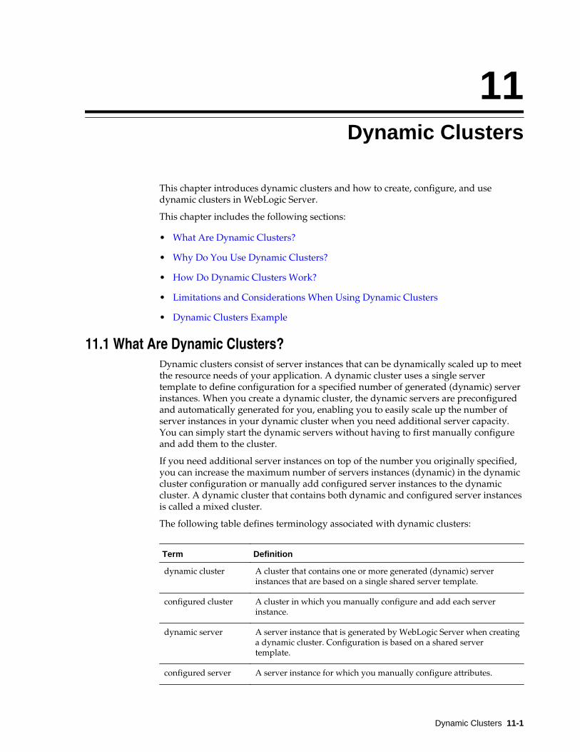
11Dynamic Clusters
This chapter introduces dynamic clusters and how to create, configure, and usedynamic clusters in WebLogic Server.
This chapter includes the following sections:
• What Are Dynamic Clusters?
• Why Do You Use Dynamic Clusters?
• How Do Dynamic Clusters Work?
• Limitations and Considerations When Using Dynamic Clusters
• Dynamic Clusters Example
11.1 What Are Dynamic Clusters?Dynamic clusters consist of server instances that can be dynamically scaled up to meetthe resource needs of your application. A dynamic cluster uses a single servertemplate to define configuration for a specified number of generated (dynamic) serverinstances. When you create a dynamic cluster, the dynamic servers are preconfiguredand automatically generated for you, enabling you to easily scale up the number ofserver instances in your dynamic cluster when you need additional server capacity.You can simply start the dynamic servers without having to first manually configureand add them to the cluster.
If you need additional server instances on top of the number you originally specified,you can increase the maximum number of servers instances (dynamic) in the dynamiccluster configuration or manually add configured server instances to the dynamiccluster. A dynamic cluster that contains both dynamic and configured server instancesis called a mixed cluster.
The following table defines terminology associated with dynamic clusters:
Term Definition
dynamic cluster A cluster that contains one or more generated (dynamic) serverinstances that are based on a single shared server template.
configured cluster A cluster in which you manually configure and add each serverinstance.
dynamic server A server instance that is generated by WebLogic Server when creatinga dynamic cluster. Configuration is based on a shared servertemplate.
configured server A server instance for which you manually configure attributes.
Dynamic Clusters 11-1
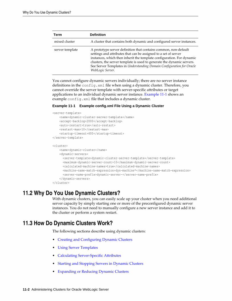
Term Definition
mixed cluster A cluster that contains both dynamic and configured server instances.
server template A prototype server definition that contains common, non-defaultsettings and attributes that can be assigned to a set of serverinstances, which then inherit the template configuration. For dynamicclusters, the server template is used to generate the dynamic servers.See Server Templates in Understanding Domain Configuration for OracleWebLogic Server.
You cannot configure dynamic servers individually; there are no server instancedefinitions in the config.xml file when using a dynamic cluster. Therefore, youcannot override the server template with server-specific attributes or targetapplications to an individual dynamic server instance. Example 11-1 shows anexample config.xml file that includes a dynamic cluster.
Example 11-1 Example config.xml File Using a Dynamic Cluster
<server-template> <name>dynamic-cluster-server-template</name> <accept-backlog>2000</accept-backlog> <auto-restart>true</auto-restart> <restart-max>10</restart-max> <startup-timeout>600</startup-timeout></server-template> <cluster> <name>dynamic-cluster</name> <dynamic-servers> <server-template>dynamic-cluster-server-template</server-template> <maximum-dynamic-server-count>10</maximum-dynamic-server-count> <calculated-machine-names>true</calculated-machine-names> <machine-name-match-expression>dyn-machine*</machine-name-match-expression> <server-name-prefix>dynamic-server-</server-name-prefix> </dynamic-servers></cluster>
11.2 Why Do You Use Dynamic Clusters?With dynamic clusters, you can easily scale up your cluster when you need additionalserver capacity by simply starting one or more of the preconfigured dynamic serverinstances. You do not need to manually configure a new server instance and add it tothe cluster or perform a system restart.
11.3 How Do Dynamic Clusters Work?The following sections describe using dynamic clusters:
• Creating and Configuring Dynamic Clusters
• Using Server Templates
• Calculating Server-Specific Attributes
• Starting and Stopping Servers in Dynamic Clusters
• Expanding or Reducing Dynamic Clusters
Why Do You Use Dynamic Clusters?
11-2 Administering Clusters for Oracle WebLogic Server
• Using Whole Server Migration with Dynamic Clusters
• Deploying Applications to Dynamic Clusters
• Using WebLogic Web Server Plug-Ins with Dynamic Clusters
11.3.1 Creating and Configuring Dynamic ClustersWhen you create a dynamic cluster, you perform the following actions:
• Specify the number of server instances you anticipate needing at peak load
• Create or select the server template upon which you want to base serverconfiguration
• Define how WebLogic Server should calculate server-specific attributes
WebLogic Server then generates the specified number of dynamic server instances andapplies the calculated attribute values to each dynamic server instance.
Note:
Ensure you have the performance capacity to handle the maximum number ofserver instances you specify in the dynamic cluster configuration. Forinformation on design and deployment best practices when creating a cluster,see Clustering Best Practices.
You create dynamic clusters using WebLogic Scripting Tool (WLST), the WebLogicServer Administration Console, or the Fusion Middleware Control (FMWC)component of Enterprise Manager (EM).
Example 11-2 demonstrates using WLST. For information about using the WebLogicServer Administration Console, see Create dynamic clusters in the Oracle WebLogicServer Administration Console Online Help. For information about using FMWC, see Create a new dynamic cluster in Administering Oracle WebLogic Server with FusionMiddleware Control. When creating a dynamic cluster in either console, WebLogicServer creates the server template, dynamic cluster, and specified number of serverinstances for you. You do not have to specify them individually. You can configuredynamic clusters using any of the administration tools listed in Summary of SystemAdministration Tools and APIs in Understanding Oracle WebLogic Server.
11.3.2 Using Server TemplatesServer templates define common configuration attributes that a set of server instancesshare. Dynamic clusters use server templates for dynamic server configuration.
For more information about server templates, see Server Templates in UnderstandingDomain Configuration for Oracle WebLogic Server.
11.3.3 Calculating Server-Specific AttributesYou cannot configure individual dynamic server instances or override values in theserver template at the dynamic server level when using a dynamic cluster. Server-specific attributes, such as server name, machines, and listen ports, must be calculatedusing the information provided when creating the dynamic cluster.
How Do Dynamic Clusters Work?
Dynamic Clusters 11-3
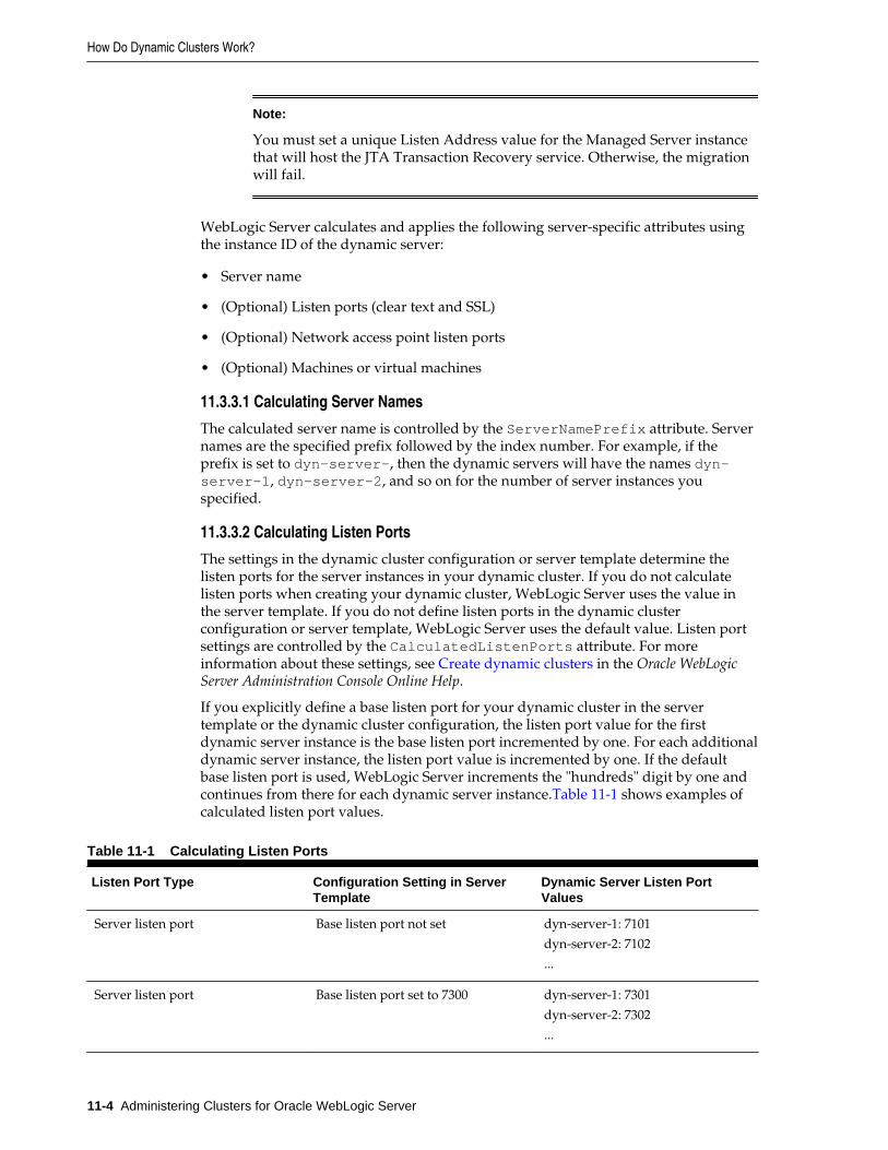
Note:
You must set a unique Listen Address value for the Managed Server instancethat will host the JTA Transaction Recovery service. Otherwise, the migrationwill fail.
WebLogic Server calculates and applies the following server-specific attributes usingthe instance ID of the dynamic server:
• Server name
• (Optional) Listen ports (clear text and SSL)
• (Optional) Network access point listen ports
• (Optional) Machines or virtual machines
11.3.3.1 Calculating Server Names
The calculated server name is controlled by the ServerNamePrefix attribute. Servernames are the specified prefix followed by the index number. For example, if theprefix is set to dyn-server-, then the dynamic servers will have the names dyn-server-1, dyn-server-2, and so on for the number of server instances youspecified.
11.3.3.2 Calculating Listen Ports
The settings in the dynamic cluster configuration or server template determine thelisten ports for the server instances in your dynamic cluster. If you do not calculatelisten ports when creating your dynamic cluster, WebLogic Server uses the value inthe server template. If you do not define listen ports in the dynamic clusterconfiguration or server template, WebLogic Server uses the default value. Listen portsettings are controlled by the CalculatedListenPorts attribute. For moreinformation about these settings, see Create dynamic clusters in the Oracle WebLogicServer Administration Console Online Help.
If you explicitly define a base listen port for your dynamic cluster in the servertemplate or the dynamic cluster configuration, the listen port value for the firstdynamic server instance is the base listen port incremented by one. For each additionaldynamic server instance, the listen port value is incremented by one. If the defaultbase listen port is used, WebLogic Server increments the "hundreds" digit by one andcontinues from there for each dynamic server instance.Table 11-1 shows examples ofcalculated listen port values.
Table 11-1 Calculating Listen Ports
Listen Port Type Configuration Setting in ServerTemplate
Dynamic Server Listen PortValues
Server listen port Base listen port not set dyn-server-1: 7101
dyn-server-2: 7102
...
Server listen port Base listen port set to 7300 dyn-server-1: 7301
dyn-server-2: 7302
...
How Do Dynamic Clusters Work?
11-4 Administering Clusters for Oracle WebLogic Server
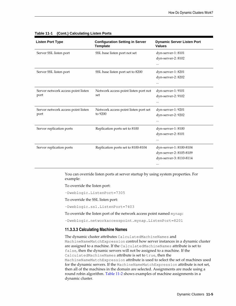
Table 11-1 (Cont.) Calculating Listen Ports
Listen Port Type Configuration Setting in ServerTemplate
Dynamic Server Listen PortValues
Server SSL listen port SSL base listen port not set dyn-server-1: 8101
dyn-server-2: 8102
...
Server SSL listen port SSL base listen port set to 8200 dyn-server-1: 8201
dyn-server-2: 8202
...
Server network access point listenport
Network access point listen port notset
dyn-server-1: 9101
dyn-server-2: 9102
...
Server network access point listenport
Network access point listen port setto 9200
dyn-server-1: 9201
dyn-server-2: 9202
...
Server replication ports Replication ports set to 8100 dyn-server-1: 8100
dyn-server-2: 8101
...
Server replication ports Replication ports set to 8100-8104 dyn-server-1: 8100-8104
dyn-server-2: 8105-8109
dyn-server-3: 8110-8114
...
You can override listen ports at server startup by using system properties. Forexample:
To override the listen port:
-Dweblogic.ListenPort=7305
To override the SSL listen port:
-Dweblogic.ssl.ListenPort=7403
To override the listen port of the network access point named mynap:
-Dweblogic.networkaccesspoint.mynap.ListenPort=8201
11.3.3.3 Calculating Machine Names
The dynamic cluster attributes CalculatedMachineNames andMachineNameMatchExpression control how server instances in a dynamic clusterare assigned to a machine. If the CalculatedMachineNames attribute is set tofalse, then the dynamic servers will not be assigned to a machine. If theCalculatedMachineNames attribute is set to true, then theMachineNameMatchExpression attribute is used to select the set of machines usedfor the dynamic servers. If the MachineNameMatchExpression attribute is not set,then all of the machines in the domain are selected. Assignments are made using around robin algorithm. Table 11-2 shows examples of machine assignments in adynamic cluster.
How Do Dynamic Clusters Work?
Dynamic Clusters 11-5
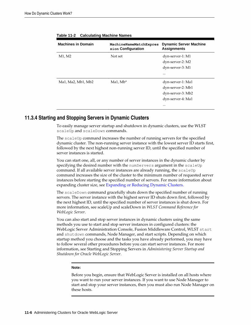
Table 11-2 Calculating Machine Names
Machines in Domain MachineNameMatchExpression Configuration
Dynamic Server MachineAssignments
M1, M2 Not set dyn-server-1: M1
dyn-server-2: M2
dyn-server-3: M1
...
Ma1, Ma2, Mb1, Mb2 Ma1, Mb* dyn-server-1: Ma1
dyn-server-2: Mb1
dyn-server-3: Mb2
dyn-server-4: Ma1
...
11.3.4 Starting and Stopping Servers in Dynamic ClustersTo easily manage server startup and shutdown in dynamic clusters, use the WLSTscaleUp and scaleDown commands.
The scaleUp command increases the number of running servers for the specifieddynamic cluster. The non-running server instance with the lowest server ID starts first,followed by the next highest non-running server ID, until the specified number ofserver instances is started.
You can start one, all, or any number of server instances in the dynamic cluster byspecifying the desired number with the numServers argument in the scaleUpcommand. If all available server instances are already running, the scaleUpcommand increases the size of the cluster to the minimum number of requested serverinstances before starting the specified number of servers. For more information aboutexpanding cluster size, see Expanding or Reducing Dynamic Clusters.
The scaleDown command gracefully shuts down the specified number of runningservers. The server instance with the highest server ID shuts down first, followed bythe next highest ID, until the specified number of server instances is shut down. Formore information, see scaleUp and scaleDown in WLST Command Reference forWebLogic Server.
You can also start and stop server instances in dynamic clusters using the samemethods you use to start and stop server instances in configured clusters: theWebLogic Server Administration Console, Fusion Middleware Control, WLST startand shutdown commands, Node Manager, and start scripts. Depending on whichstartup method you choose and the tasks you have already performed, you may haveto follow several other procedures before you can start server instances. For moreinformation, see Starting and Stopping Servers in Administering Server Startup andShutdown for Oracle WebLogic Server.
Note:
Before you begin, ensure that WebLogic Server is installed on all hosts whereyou want to run your server instances. If you want to use Node Manager tostart and stop your server instances, then you must also run Node Manager onthese hosts.
How Do Dynamic Clusters Work?
11-6 Administering Clusters for Oracle WebLogic Server
11.3.5 Expanding or Reducing Dynamic ClustersWhen you create a dynamic cluster, WebLogic Server generates the number ofdynamic servers you specify. Before you decide upon the number of server instances,ensure you have the performance capacity to handle the desired number.
The dynamic server instances are based on the configuration you specified in theserver template and calculated attributes.
• To expand your cluster, start any number of the preconfigured dynamic servers.
• To shrink your dynamic cluster, shut down the excess number of dynamic servers.
If you need additional server capacity on top of the number of server instances youoriginally specified, increase the maximum number of dynamic servers in the dynamiccluster configuration. To reduce the number of server instances in the dynamic cluster,decrease the value of the maximum number of dynamic servers attribute. Beforelowering this value, shut down the server instances you plan to remove.
You can also use the WLST scaleUp and scaleDown commands to manage yourdynamic cluster. To increase the number of dynamic servers in the dynamic cluster,use the scaleUp command and enable the updateConfiguration argument. WLSTwill increase the maximum size of the cluster by the specified number of servers andstart the server instances.
To decrease the maximum size of the dynamic cluster, use the scaleDown commandand enable the updateConfiguration argument. WLST will gracefully shut downthe specified number of running server instances and remove them from the dynamiccluster. For more information, see scaleUp and scaleDown in WLST CommandReference for WebLogic Server.
Note:
You can only use the WLST scaleUp and scaleDown commands withdynamic server instances. In a mixed cluster, containing both manuallyconfigured and dynamic server instances, the scaleUp and scaleDowncommands ignore the configured servers. You must manually start and stopconfigured server instances in a mixed cluster.
For example, a cluster contains two running dynamic servers and two non-running configured servers. If you use the scaleUp command, WLST addsone additional dynamic server instance to your cluster and starts the dynamicserver.
The WLST scaleUp and scaleDown commands provide ways to manually scaleyour dynamic cluster. For automatic scaling, you can configure elasticity for yourdynamic cluster. Elasticity enables a dynamic cluster to perform scaling and re-provisioning operations automatically in response to demand or on a calendar basedschedule. WebLogic Server provides elasticity for dynamic clusters through thePolicies and Actions system of the WebLogic Diagnostic Framework (WLDF). Formore information, see Configuring Elasticity in Dynamic Clusters for Oracle WebLogicServer.
How Do Dynamic Clusters Work?
Dynamic Clusters 11-7
11.3.6 Using Whole Server Migration with Dynamic ClustersWebLogic Server supports whole server migration with dynamic and mixed clusters.While configuration differs depending on the cluster type, whole server migrationbehavior is the same for all clusters. For information on how to enable whole servermigration for dynamic clusters, see Whole Server Migration with Dynamic and MixedClusters.
11.3.7 Deploying Applications to Dynamic ClustersWhen deploying applications to a dynamic cluster, you must target the application tothe entire cluster. You cannot target an application to an individual server instancebecause dynamic clusters do not have individual dynamic server configuration. Whenyou deploy an application to the dynamic cluster, all servers in the cluster, bothdynamic and static, will deploy the application.
To deploy an application to a dynamic cluster, follow the same process as deploying toconfigured clusters. For more information, see Deploy Applications and ApplicationDeployment for Clustered Configurations.
For a broad discussion of deployment topics, see Deploying Applications to OracleWebLogic Server.
11.3.8 Using WebLogic Web Server Plug-Ins with Dynamic ClustersDynamic clusters provide the same WebLogic Web server plug-in support asconfigured clusters. By default, a Web server plug-in uses the DynamicServerListparameter to receive information about cluster changes, such as new server instancesin a configured or dynamic cluster. Upon recognizing a cluster membership change,the plug-in automatically updates its server list.
For general information about using Web server plug-ins with WebLogic Server, see Using Oracle WebLogic Server Proxy Plug-Ins 12.2.1.2. For more information about theDynamicServerList parameter or the WebLogicCluster parameter (requiredwhen proxying to a WebLogic Server cluster), see General Parameters for Web ServerPlug-Ins in Using Oracle WebLogic Server Proxy Plug-Ins 12.2.1.2.
11.4 Limitations and Considerations When Using Dynamic ClustersWhen using dynamic clusters with WebLogic Server, note the following limitationsand considerations:
• You cannot override values in the server template at the individual dynamic serverlevel because there are no individual server definitions in the config.xml filewhen using dynamic clusters.
• You need to ensure that the values are set on server template, such that eachDynamic server inherits unique values for required parameters. For example, setthe value to LLR_DYN_SRV_${id} for LLR table under Server Templateconfiguration. ${id} would be replaced with server number at runtime for eachdynamic server.
Note: For more information see Servers: Configuration: General in the OracleWebLogic Server Administration Console Online Help
Limitations and Considerations When Using Dynamic Clusters
11-8 Administering Clusters for Oracle WebLogic Server
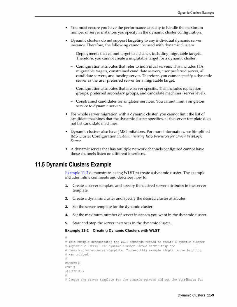
• You must ensure you have the performance capacity to handle the maximumnumber of server instances you specify in the dynamic cluster configuration.
• Dynamic clusters do not support targeting to any individual dynamic serverinstance. Therefore, the following cannot be used with dynamic clusters:
– Deployments that cannot target to a cluster, including migratable targets.Therefore, you cannot create a migratable target for a dynamic cluster.
– Configuration attributes that refer to individual servers. This includes JTAmigratable targets, constrained candidate servers, user preferred server, allcandidate servers, and hosting server. Therefore, you cannot specify a dynamicserver as the user preferred server for a migratable target.
– Configuration attributes that are server specific. This includes replicationgroups, preferred secondary groups, and candidate machines (server level).
– Constrained candidates for singleton services. You cannot limit a singletonservice to dynamic servers.
• For whole server migration with a dynamic cluster, you cannot limit the list ofcandidate machines that the dynamic cluster specifies, as the server template doesnot list candidate machines.
• Dynamic clusters also have JMS limitations. For more information, see SimplifiedJMS Cluster Configuration in Administering JMS Resources for Oracle WebLogicServer.
• A dynamic server that has multiple network channels configured cannot havethose channels listen on different interfaces.
11.5 Dynamic Clusters ExampleExample 11-2 demonstrates using WLST to create a dynamic cluster. The exampleincludes inline comments and describes how to:
1. Create a server template and specify the desired server attributes in the servertemplate.
2. Create a dynamic cluster and specify the desired cluster attributes.
3. Set the server template for the dynamic cluster.
4. Set the maximum number of server instances you want in the dynamic cluster.
5. Start and stop the server instances in the dynamic cluster.
Example 11-2 Creating Dynamic Clusters with WLST
## This example demonstrates the WLST commands needed to create a dynamic cluster# (dynamic-cluster). The dynamic cluster uses a server template # dynamic-cluster-server-template. To keep this example simple, error handling# was omitted.#connect()edit()startEdit()## Create the server template for the dynamic servers and set the attributes for
Dynamic Clusters Example
Dynamic Clusters 11-9
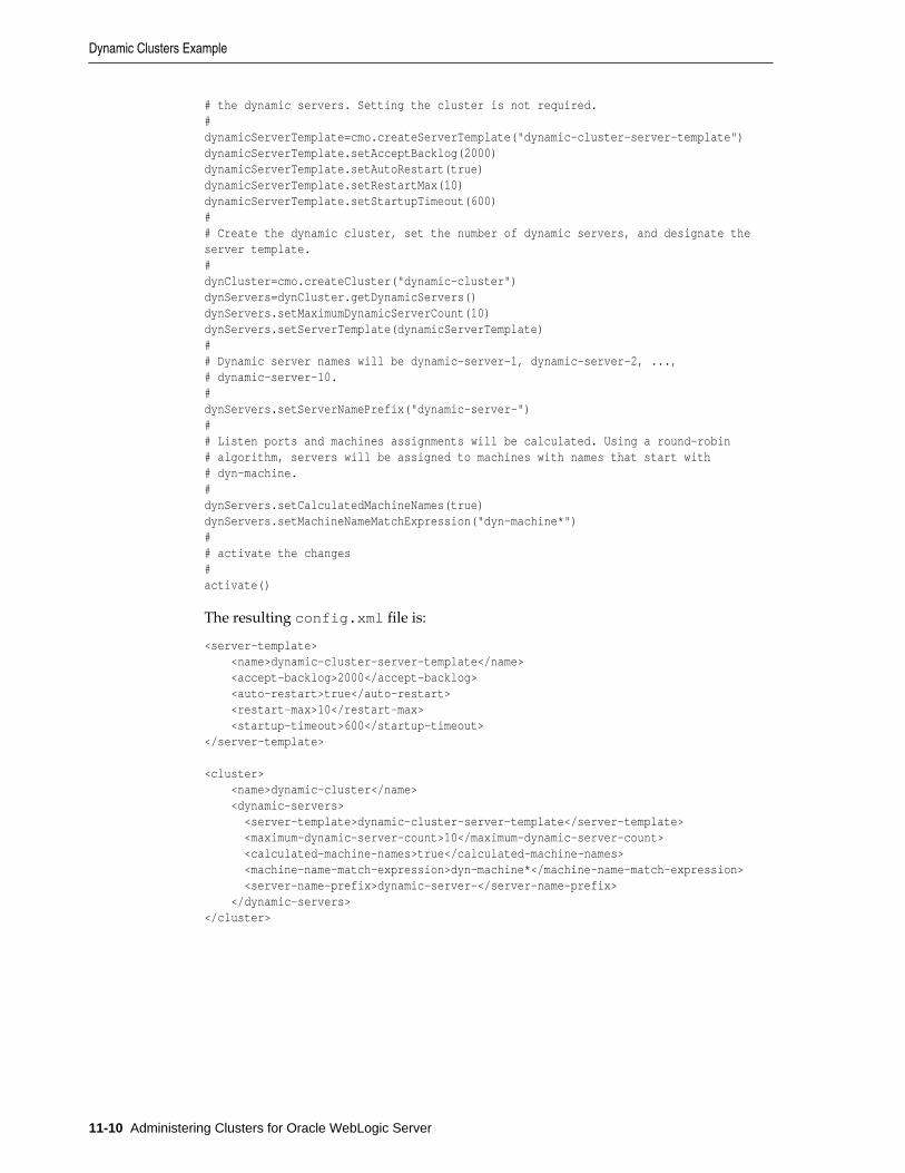
# the dynamic servers. Setting the cluster is not required.#dynamicServerTemplate=cmo.createServerTemplate("dynamic-cluster-server-template")dynamicServerTemplate.setAcceptBacklog(2000)dynamicServerTemplate.setAutoRestart(true)dynamicServerTemplate.setRestartMax(10)dynamicServerTemplate.setStartupTimeout(600)## Create the dynamic cluster, set the number of dynamic servers, and designate the server template.#dynCluster=cmo.createCluster("dynamic-cluster")dynServers=dynCluster.getDynamicServers()dynServers.setMaximumDynamicServerCount(10)dynServers.setServerTemplate(dynamicServerTemplate)## Dynamic server names will be dynamic-server-1, dynamic-server-2, ...,# dynamic-server-10.#dynServers.setServerNamePrefix("dynamic-server-")## Listen ports and machines assignments will be calculated. Using a round-robin# algorithm, servers will be assigned to machines with names that start with# dyn-machine.#dynServers.setCalculatedMachineNames(true)dynServers.setMachineNameMatchExpression("dyn-machine*")## activate the changes#activate()
The resulting config.xml file is:
<server-template> <name>dynamic-cluster-server-template</name> <accept-backlog>2000</accept-backlog> <auto-restart>true</auto-restart> <restart-max>10</restart-max> <startup-timeout>600</startup-timeout></server-template>
<cluster> <name>dynamic-cluster</name> <dynamic-servers> <server-template>dynamic-cluster-server-template</server-template> <maximum-dynamic-server-count>10</maximum-dynamic-server-count> <calculated-machine-names>true</calculated-machine-names> <machine-name-match-expression>dyn-machine*</machine-name-match-expression> <server-name-prefix>dynamic-server-</server-name-prefix> </dynamic-servers></cluster>
Dynamic Clusters Example
11-10 Administering Clusters for Oracle WebLogic Server
12Configuring and Managing Coherence
Clusters
This chapter provides instructions for defining Coherence clusters in a WebLogicServer domain and how to associate a Coherence Cluster with multiple WebLogicServer clusters. The instructions in this chapter assume that a WebLogic Serverdomain has already been created.
This chapter includes the following sections:
• Overview of Coherence Clusters
• Setting Up a Coherence Cluster
• Creating Coherence Deployment Tiers
• Configuring a Coherence Cluster
• Configuring Managed Coherence Servers
• Using a Single-Server Cluster
• Using WLST with Coherence
12.1 Overview of Coherence ClustersCoherence clusters consist of multiple managed Coherence server instances thatdistribute data in-memory to increase application scalability, availability, andperformance. An application interacts with the data in a local cache and thedistribution and backup of the data is automatically performed across clustermembers.
Coherence clusters are different than WebLogic Server clusters. They use differentclustering protocols and are configured separately. Multiple WebLogic Server clusterscan be associated with a Coherence cluster and a WebLogic Server domain typicallycontains a single Coherence cluster. Managed servers that are configured as Coherencecluster members are referred to as managed Coherence servers.
Managed Coherence servers can be explicitly associated with a Coherence cluster orthey can be associated with a WebLogic Server cluster that is associated with aCoherence cluster. Managed Coherence servers are typically setup in tiers that arebased on their type: a data tier for storing data, an application tier for hostingapplications, and a proxy tier that allows external clients to access caches.
Figure 12-1 shows a conceptual view of a Coherence cluster in a WebLogic Serverdomain:
Configuring and Managing Coherence Clusters 12-1
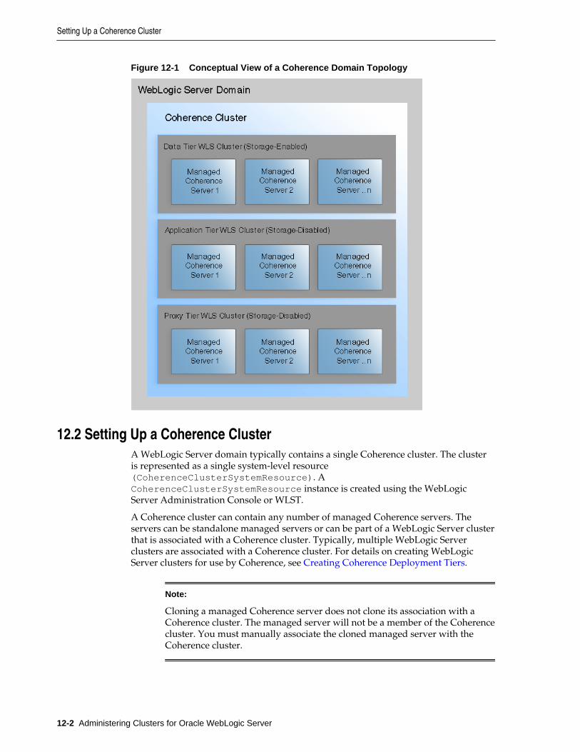
Figure 12-1 Conceptual View of a Coherence Domain Topology
12.2 Setting Up a Coherence ClusterA WebLogic Server domain typically contains a single Coherence cluster. The clusteris represented as a single system-level resource(CoherenceClusterSystemResource). ACoherenceClusterSystemResource instance is created using the WebLogicServer Administration Console or WLST.
A Coherence cluster can contain any number of managed Coherence servers. Theservers can be standalone managed servers or can be part of a WebLogic Server clusterthat is associated with a Coherence cluster. Typically, multiple WebLogic Serverclusters are associated with a Coherence cluster. For details on creating WebLogicServer clusters for use by Coherence, see Creating Coherence Deployment Tiers.
Note:
Cloning a managed Coherence server does not clone its association with aCoherence cluster. The managed server will not be a member of the Coherencecluster. You must manually associate the cloned managed server with theCoherence cluster.
Setting Up a Coherence Cluster
12-2 Administering Clusters for Oracle WebLogic Server
12.2.1 Define a Coherence Cluster ResourceTo define a Coherence cluster resource:
1. From the WebLogic Server Administration Console Domain Structure pane,expand Environment and click Coherence Clusters.
2. From the Summary of Coherence Clusters page, click New.
3. From the Create a Coherence Cluster Configuration page, enter a name for thecluster using the Name field. Click Next.
4. From the Coherence Cluster Addressing section, select the clustering mode or keepthe default settings. The default cluster listen port (7574) does not need to bechanged for most clusters. For details on configuring the clustering mode, see Configure Cluster Communication.
5. From the Coherence Cluster Members section, click to select the managedCoherence servers or WebLogic Server clusters that are to be part of the Coherencecluster or skip this section if managed Coherence servers and WebLogic Clustersare yet to be defined.
6. Click Finish. The Summary of Coherence Clusters screen displays and theCoherence Clusters table lists the cluster resource.
12.2.2 Create Standalone Managed Coherence ServersManaged Coherence servers are managed server instances that are associated with aCoherence cluster. Managed Coherence servers join together to form a Coherencecluster and are often referred to as cluster members. Cluster members have seniorityand the senior member performs cluster tasks (for example, issuing the cluster heartbeat).
Note:
• Managed Coherence servers and standalone Coherence cluster members(those that are not managed within a WebLogic Server domain) can jointhe same cluster. However, standalone cluster members cannot bemanaged from within a WebLogic Server domain; operationalconfiguration and application lifecycles must be manually administeredand monitored.
• The Administration Server is typically not used as a managed Coherenceserver in a production environment.
Managed Coherence servers are distinguished by their role in the cluster. A bestpractice is to use different managed server instances (and preferably differentWebLogic Server clusters) for each cluster role.
• storage-enabled – a managed Coherence server that is responsible for storing datain the cluster. Coherence applications are packaged as Grid ARchives (GAR) anddeployed on storage-enabled managed Coherence servers.
• storage-disabled – a managed Coherence server that is not responsible for storingdata and is used to host Coherence applications (cache clients). A Coherence
Setting Up a Coherence Cluster
Configuring and Managing Coherence Clusters 12-3
application GAR is packaged within an EAR and deployed on storage-disabledmanaged Coherence servers.
• proxy – a managed Coherence server that is storage-disabled and allows externalclients (non-cluster members) to use a cache. A Coherence application GAR isdeployed on managed Coherence proxy servers.
To create managed Coherence servers:
1. From the WebLogic Server Administration Console Domain Structure pane,expand Environment and click Servers.
2. Click New to create a new managed server.
3. From the Create a New Server page, enter the server's properties as required.
4. Select whether to make the server part of a WebLogic Server cluster. For details oncreating WebLogic Server clusters for use as a Coherence deployment tier, see Creating Coherence Deployment Tiers.
5. Click Finish. The Summary of Servers page displays and the new server is listed.
6. Select the new server to configure its settings.
7. From the Coherence tab, use the Coherence Cluster drop-down list and select aCoherence cluster to associate it with this managed server. By default, the managedserver is a storage-enabled Coherence member as indicated by the Local StorageEnabled field. For details on changing managed Coherence settings, see Configuring Managed Coherence Servers.
8. Click Save. The Summary of Servers page displays.
9. From the Summary of Servers page, click the Control tab and start the server.
12.3 Creating Coherence Deployment TiersCoherence supports different topologies within a WebLogic Server domain to providevarying levels of performance, scalability, and ease of use. For example, duringdevelopment, a single standalone managed server instance may be used as both acache server and a cache client. The single-server topology is easy to setup and use,but does not provide optimal performance or scalability. For production, Coherence istypically setup using WebLogic Server Clusters. A WebLogic Server cluster is used asa Coherence data tier and hosts one or more cache servers; a different WebLogicServer cluster is used as a Coherence application tier and hosts one or more cacheclients; and (if required) different WebLogic Server clusters are used for the Coherenceproxy tier that hosts one or more managed Coherence proxy servers and theCoherence extend client tier that hosts extend clients. The tiered topology approachprovides optimal scalability and performance.
The instructions in this section use both the Clusters Settings page and ServersSettings page in the WebLogic Server Administration Console to create Coherencedeployment tiers. WebLogic Server clusters and managed servers instances can beassociated with a Coherence cluster resource using the ClusterMBean andServerMBean MBeans, respectively. Managed servers that are associated with aWebLogic Server cluster inherit the cluster's Coherence settings. However, the settingsmay not be reflected in the Servers Settings page.
Creating Coherence Deployment Tiers
12-4 Administering Clusters for Oracle WebLogic Server
12.3.1 Configuring and Managing a Coherence Data TierA Coherence Data tier is a WebLogic Server cluster that is associated with a Coherencecluster and hosts any number of storage-enabled managed Coherence servers.Managed Coherence servers in the data tier store and distribute data (both primaryand backup) on the cluster. The number of managed Coherence servers that arerequired in a data tier depends on the expected amount of data that is stored in theCoherence cluster and the amount of memory available on each server. In addition, acluster must contain a minimum of four physical computers to avoid the possibility ofdata loss during a computer failure.
Coherence artifacts (such as Coherence configuration files, POF serialization classes,filters, entry processors, and aggregators) are packaged as a GAR and deployed on thedata tier. For details on packaging and deploying Coherence applications, see Developing Oracle Coherence Applications for Oracle WebLogic Server. For details oncalculating cache size and hardware requirements, see the production checklist in Administering Oracle Coherence.
12.3.1.1 Create a Coherence Data Tier
To create a Coherence data tier:
1. Create a WebLogic Server cluster. For details, see Setting up WebLogic Clusters.
2. From the Summary of Clusters page, select the cluster from the Clusters table toconfigure it.
3. From the Coherence tab, use the Coherence Cluster drop-down list and select aCoherence cluster to associate it with this WebLogic Server cluster. By default, themanaged servers assigned to this WebLogic Server cluster will be storage-enabledCoherence members as indicated by the Local Storage Enabled field.
4. If using Coherence for HTTP session replication, select either the Coherence WebLocal Storage Enabled or the Coherence Web Federated Storage Enabled optionto enable session replication. When selecting the federated storage option, thedefault federation topology which is configured is used. For details aboutconfiguring federation, see Configuring Cache Federation.
12.3.1.2 Create Managed Coherence Servers for a Data Tier
To create managed servers for a Coherence data tier:
1. From the WebLogic Server Administration Console Domain Structure pane,expand Environment and, click Servers.
2. Click New to create a new managed server.
3. From the Create a New Server page, enter the server's properties as required.
4. Click the Yes option to add the server to an existing cluster and use the drop-downlist to select the data tier WebLogic Server cluster. The managed server inherits theCoherence settings from the data tier WebLogic Server cluster.
5. Click Finish. The Summary of Servers page displays and the new server is listed.
6. Repeat these steps to create additional managed servers as required.
7. From the Control tab, select the servers to start and click Start.
Creating Coherence Deployment Tiers
Configuring and Managing Coherence Clusters 12-5
12.3.2 Configuring and Managing a Coherence Application TierA Coherence Application tier is a WebLogic Server cluster that is associated with aCoherence cluster and hosts any number of storage-disabled managed Coherenceservers. Managed Coherence servers in the application tier host applications (cachefactory clients) and are Coherence cluster members. Multiple application tiers can becreated for different applications.
Clients in the application tier are deployed as EARs and implemented using Java EEstandards such as servlet, JSP, and EJB. Coherence artifacts (such as Coherenceconfiguration files, POF serialization classes, filters, entry processors, and aggregators)must be packaged as a GAR and also deployed within an EAR. For details onpackaging and deploying Coherence applications, see Developing Oracle CoherenceApplications for Oracle WebLogic Server.
12.3.2.1 Create a Coherence Application Tier
To create a Coherence application tier:
1. Create a WebLogic Server cluster. For details, see Setting up WebLogic Clusters.
2. From the Summary of Clusters page, select the cluster from the Clusters table toconfigure it.
3. From the Coherence tab, use the Coherence Cluster drop-down list and select aCoherence cluster to associate it with this WebLogic Server cluster.
4. Click the Local Storage Enabled check box to remove the check mark and disablestorage on the application tier. The managed Coherence servers assigned to thisWebLogic Server cluster will be storage-disabled Coherence members (cachefactory clients). Servers in the application tier should never be used to store cachedata. Storage-enabled servers require resources to store and distribute data and canadversely affect client performance.
5. Click Save.
12.3.2.2 Create Managed Coherence Servers for an Application Tier
To create managed servers for a Coherence application tier:
1. From the WebLogic Server Administration Console Domain Structure pane,expand Environment and, click Servers.
2. Click New to create a new managed server.
3. From the Create a New Server page, enter the server's properties as required.
4. Click the Yes option to add the server to an existing cluster and use the drop-downlist to select the application tier WebLogic Server cluster. The managed serverinherits the Coherence settings from the data tier WebLogic Server cluster.
5. Click Finish. The Summary of Servers page displays and the new server is listed.
6. Repeat these steps to create additional managed servers as required.
7. From the Control tab, select the servers to start and click Start.
Creating Coherence Deployment Tiers
12-6 Administering Clusters for Oracle WebLogic Server
12.3.3 Configuring and Managing a Coherence Proxy TierA Coherence proxy tier is a WebLogic Server cluster that is associated with aCoherence cluster and hosts any number of managed Coherence proxy servers.Managed Coherence proxy servers allow Coherence*Extend clients to use Coherencecaches without being cluster members. The number of managed Coherence proxyservers that are required in a proxy tier depends on the number of expected clients. Atleast two proxy servers must be created to allow for load balancing; however,additional servers may be required when supporting a large number of clientconnections and requests.
For details on Coherence*Extend and creating extend clients, see Developing RemoteClients for Oracle Coherence.
12.3.3.1 Create a Coherence Proxy Tier
To create a Coherence proxy tier:
1. Create a WebLogic Server cluster. For details, see Setting up WebLogic Clusters.
2. From the Summary of Clusters page, select the cluster from the Clusters table toconfigure it.
3. From the Coherence tab, use the Coherence Cluster drop-down list and select aCoherence cluster to associate it with this WebLogic Server cluster.
4. Click the Local Storage Enabled check box to remove the check mark and disablestorage on the proxy tier. Proxy servers should never be used to store cache data.Storage-enabled cluster members can be adversely affected by a proxy service,which requires additional resources to handle client loads.
5. Click Save.
12.3.3.2 Create Managed Coherence Servers for a Proxy Tier
To create managed servers for a Coherence proxy tier:
1. From the WebLogic Server Administration Console Domain Structure pane,expand Environment and, click Servers.
2. Click New to create a new managed server.
3. From the Create a New Server page, enter the server's properties as required.
4. Click the Yes option to add the server to an existing cluster and use the drop-downlist to select the proxy tier WebLogic Server cluster. The managed server inheritsthe Coherence settings from the data tier WebLogic Server cluster.
5. Click Finish. The Summary of Servers page displays and the new server is listed.
6. Repeat these steps to create additional managed servers as required.
7. From the Control tab, select the servers to start and click Start.
12.3.3.3 Configure Coherence Proxy Services
Coherence proxy services are clustered services that manage remote connections fromextend clients. Proxy services are defined and configured in a coherence-cache-config.xml file within the <proxy-scheme> element. The definition includes,
Creating Coherence Deployment Tiers
Configuring and Managing Coherence Clusters 12-7
among other settings, the TCP listener address (IP, or DNS name, and port) that isused to accept client connections. For details on the <proxy-scheme> element, see Developing Applications with Oracle Coherence.There are two ways to setup proxyservices: using a name service and using an address provider. The naming serviceprovides an efficient setup and is typically preferred in a Coherence proxy tier.
12.3.3.3.1 Using a Name Service
A name service is a specialized listener that allows extend clients to connect to a proxyservice by name. Clients connect to the name service, which returns the addresses ofall proxy services on the cluster.
Note:
If a domain includes multiple tiers (for example, a data tier, an applicationtier, and a proxy tier), then the proxy tier should be started first, before a clientcan connect to the proxy.
A name service automatically starts on port 7574 (the same default port that the TCMPsocket uses) when a proxy service is configured on a managed Coherence proxyserver. The reuse of the same port minimizes the number of ports that are used byCoherence and simplifies firewall configuration.
To configure a proxy service and enable the name service on the default TCMP port:
1. Edit the coherence-cache-config.xml file and create a <proxy-scheme>definition and do not explicitly define a socket address. The following exampledefines a proxy service that is named TcpExtend and automatically enables acluster name service. A proxy address and ephemeral port is automaticallyassigned and registered with the cluster's name service.
...<caching-schemes> ... <proxy-scheme> <service-name>TcpExtend</service-name> <autostart>true</autostart> </proxy-scheme></caching-schemes>...
2. Deploy the coherence-cache-config.xml file to each managed Coherenceproxy server in the Coherence proxy tier. Typically, the coherence-cache-config.xml file is included in a GAR file. However, for the proxy tier, use acluster cache configuration file to override the coherence-cache-config.xmlfile that is located in the GAR. This allows a single GAR to be deployed to thecluster and the proxy tier. For details on using a cluster cache configuration file, see Overriding a Cache Configuration File.
To connect to a name service, a client's coherence-cache-config.xml file mustinclude a <name-service-addresses> element, within the <tcp-initiator>element, of a remote cache or remote invocation definition. The <name-service-addresses> element provides the socket address of a name service that is on amanaged Coherence proxy server. The following example defines a remote cachedefinition and specifies a name service listening at host 192.168.1.5 on port 7574.The client automatically connects to the name service and gets a list of all managedCoherence proxy servers that contain a TcpExtend proxy service. The cache on the
Creating Coherence Deployment Tiers
12-8 Administering Clusters for Oracle WebLogic Server
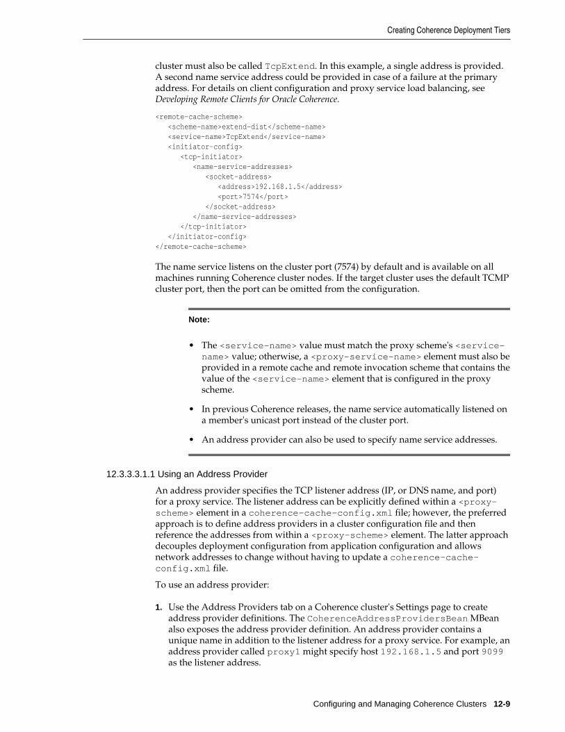
cluster must also be called TcpExtend. In this example, a single address is provided.A second name service address could be provided in case of a failure at the primaryaddress. For details on client configuration and proxy service load balancing, see Developing Remote Clients for Oracle Coherence.
<remote-cache-scheme> <scheme-name>extend-dist</scheme-name> <service-name>TcpExtend</service-name> <initiator-config> <tcp-initiator> <name-service-addresses> <socket-address> <address>192.168.1.5</address> <port>7574</port> </socket-address> </name-service-addresses> </tcp-initiator> </initiator-config></remote-cache-scheme>
The name service listens on the cluster port (7574) by default and is available on allmachines running Coherence cluster nodes. If the target cluster uses the default TCMPcluster port, then the port can be omitted from the configuration.
Note:
• The <service-name> value must match the proxy scheme's <service-name> value; otherwise, a <proxy-service-name> element must also beprovided in a remote cache and remote invocation scheme that contains thevalue of the <service-name> element that is configured in the proxyscheme.
• In previous Coherence releases, the name service automatically listened ona member's unicast port instead of the cluster port.
• An address provider can also be used to specify name service addresses.
12.3.3.3.1.1 Using an Address Provider
An address provider specifies the TCP listener address (IP, or DNS name, and port)for a proxy service. The listener address can be explicitly defined within a <proxy-scheme> element in a coherence-cache-config.xml file; however, the preferredapproach is to define address providers in a cluster configuration file and thenreference the addresses from within a <proxy-scheme> element. The latter approachdecouples deployment configuration from application configuration and allowsnetwork addresses to change without having to update a coherence-cache-config.xml file.
To use an address provider:
1. Use the Address Providers tab on a Coherence cluster's Settings page to createaddress provider definitions. The CoherenceAddressProvidersBean MBeanalso exposes the address provider definition. An address provider contains aunique name in addition to the listener address for a proxy service. For example, anaddress provider called proxy1 might specify host 192.168.1.5 and port 9099as the listener address.
Creating Coherence Deployment Tiers
Configuring and Managing Coherence Clusters 12-9
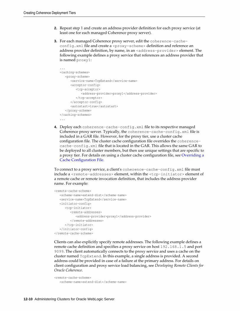
2. Repeat step 1 and create an address provider definition for each proxy service (atleast one for each managed Coherence proxy server).
3. For each managed Coherence proxy server, edit the coherence-cache-config.xml file and create a <proxy-scheme> definition and reference anaddress provider definition, by name, in an <address-provider> element. Thefollowing example defines a proxy service that references an address provider thatis named proxy1:
...<caching-schemes> <proxy-scheme> <service-name>TcpExtend</service-name> <acceptor-config> <tcp-acceptor> <address-provider>proxy1</address-provider> </tcp-acceptor> </acceptor-config> <autostart>true</autostart> </proxy-scheme></caching-schemes>...
4. Deploy each coherence-cache-config.xml file to its respective managedCoherence proxy server. Typically, the coherence-cache-config.xml file isincluded in a GAR file. However, for the proxy tier, use a cluster cacheconfiguration file. The cluster cache configuration file overrides the coherence-cache-config.xml file that is located in the GAR. This allows the same GAR tobe deployed to all cluster members, but then use unique settings that are specific toa proxy tier. For details on using a cluster cache configuration file, see Overriding aCache Configuration File.
To connect to a proxy service, a client's coherence-cache-config.xml file mustinclude a <remote-addresses> element, within the <tcp-initiator> element ofa remote cache or remote invocation definition, that includes the address providername. For example:
<remote-cache-scheme> <scheme-name>extend-dist</scheme-name> <service-name>TcpExtend</service-name> <initiator-config> <tcp-initiator> <remote-addresses> <address-provider>proxy1</address-provider> </remote-addresses> </tcp-initiator> </initiator-config></remote-cache-scheme>
Clients can also explicitly specify remote addresses. The following example defines aremote cache definition and specifies a proxy service on host 192.168.1.5 and port9099. The client automatically connects to the proxy service and uses a cache on thecluster named TcpExtend. In this example, a single address is provided. A secondaddress could be provided in case of a failure at the primary address. For details onclient configuration and proxy service load balancing, see Developing Remote Clients forOracle Coherence.
<remote-cache-scheme> <scheme-name>extend-dist</scheme-name>
Creating Coherence Deployment Tiers
12-10 Administering Clusters for Oracle WebLogic Server

<service-name>TcpExtend</service-name> <initiator-config> <tcp-initiator> <remote-addresses> <socket-address> <address>192.168.1.5</address> <port>9099</port> </socket-address> </remote-addresses> </tcp-initiator> </initiator-config></remote-cache-scheme>
12.4 Configuring a Coherence ClusterA Coherence cluster resource exposes several cluster settings that can be configuredfor a specific domain. Use the following tasks to configure cluster settings:
• Adding and Removing Coherence Cluster Members
• Setting Advanced Cluster Configuration Options
• Configure Cluster Communication
• Overriding a Cache Configuration File
• Configuring Coherence Logging
• Configuring Cache Persistence
• Configuring Cache Federation
Many of the settings use default values that can be changed as required. The followinginstructions assume that a cluster resource has already been created. For details oncreating a cluster resource, see Setting Up a Coherence Cluster. This section does notinclude instructions for securing Coherence. For security details, see Securing OracleCoherence.
Use the Coherence tab on the Coherence Cluster Settings page to configure clustercommunication. The CoherenceClusterSystemResource MBean and itsassociated CoherenceClusterResource MBean expose cluster settings. TheCoherenceClusterResource MBean provides access to multiple MBeans forconfiguring a Coherence cluster.
Note:
WLS configuration take precedence over Coherence system properties.Coherence configuration in WLS should, in general, be changed using WLSTor a Coherence cluster configuration file instead of using system properties.
12.4.1 Adding and Removing Coherence Cluster MembersAny existing managed server instance can be added to a Coherence cluster. Inaddition, managed Coherence servers can be removed from a cluster. Adding andremoving cluster members is available when configuring a Coherence Cluster and is ashortcut that is used instead of explicitly configuring each instance. However, whenadding existing managed server instances, default Coherence settings may need to be
Configuring a Coherence Cluster
Configuring and Managing Coherence Clusters 12-11
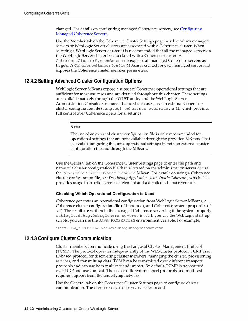
changed. For details on configuring managed Coherence servers, see ConfiguringManaged Coherence Servers.
Use the Member tab on the Coherence Cluster Settings page to select which managedservers or WebLogic Server clusters are associated with a Coherence cluster. Whenselecting a WebLogic Server cluster, it is recommended that all the managed servers inthe WebLogic Server cluster be associated with a Coherence cluster. ACoherenceClusterSystemResource exposes all managed Coherence servers astargets. A CoherenceMemberConfig MBean is created for each managed server andexposes the Coherence cluster member parameters.
12.4.2 Setting Advanced Cluster Configuration OptionsWebLogic Server MBeans expose a subset of Coherence operational settings that aresufficient for most use cases and are detailed throughout this chapter. These settingsare available natively through the WLST utility and the WebLogic ServerAdministration Console. For more advanced use cases, use an external Coherencecluster configuration file (tangosol-coherence-override.xml), which providesfull control over Coherence operational settings.
Note:
The use of an external cluster configuration file is only recommended foroperational settings that are not available through the provided MBeans. Thatis, avoid configuring the same operational settings in both an external clusterconfiguration file and through the MBeans.
Use the General tab on the Coherence Cluster Settings page to enter the path andname of a cluster configuration file that is located on the administration server or usethe CoherenceClusterSystemResource MBean. For details on using a Coherencecluster configuration file, see Developing Applications with Oracle Coherence, which alsoprovides usage instructions for each element and a detailed schema reference.
Checking Which Operational Configuration is Used
Coherence generates an operational configuration from WebLogic Server MBeans, aCoherence cluster configuration file (if imported), and Coherence system properties (ifset). The result are written to the managed Coherence server log if the system propertyweblogic.debug.DebugCoherence=true is set. If you use the WebLogic start-upscripts, you can use the JAVA_PROPERTIES environment variable. For example,
export JAVA_PROPERTIES=-Dweblogic.debug.DebugCoherence=true
12.4.3 Configure Cluster CommunicationCluster members communicate using the Tangosol Cluster Management Protocol(TCMP). The protocol operates independently of the WLS cluster protocol. TCMP is anIP-based protocol for discovering cluster members, managing the cluster, provisioningservices, and transmitting data. TCMP can be transmitted over different transportprotocols and can use both multicast and unicast. By default, TCMP is transmittedover UDP and uses unicast. The use of different transport protocols and multicastrequires support from the underlying network.
Use the General tab on the Coherence Cluster Settings page to configure clustercommunication. The CoherenceClusterParamsBean and
Configuring a Coherence Cluster
12-12 Administering Clusters for Oracle WebLogic Server
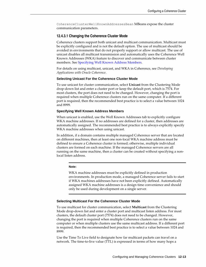
CoherenceClusterWellKnownAddressesBean MBeans expose the clustercommunication parameters.
12.4.3.1 Changing the Coherence Cluster Mode
Coherence clusters support both unicast and multicast communication. Multicast mustbe explicitly configured and is not the default option. The use of multicast should beavoided in environments that do not properly support or allow multicast. The use ofunicast disables all multicast transmission and automatically uses the Coherence WellKnown Addresses (WKA) feature to discover and communicate between clustermembers. See Specifying Well Known Address Members.
For details on using multicast, unicast, and WKA in Coherence, see DevelopingApplications with Oracle Coherence.
Selecting Unicast For the Coherence Cluster Mode
To use unicast for cluster communication, select Unicast from the Clustering Modedrop-down list and enter a cluster port or keep the default port, which is 7574. Formost clusters, the port does not need to be changed. However, changing the port isrequired when multiple Coherence clusters run on the same computer. If a differentport is required, then the recommended best practice is to select a value between 1024and 8999.
Specifying Well Known Address Members
When unicast is enabled, use the Well Known Addresses tab to explicitly configureWKA machine addresses. If no addresses are defined for a cluster, then addresses areautomatically assigned. The recommended best practice is to always explicitly specifyWKA machine addresses when using unicast.
In addition, if a domain contains multiple managed Coherence server that are locatedon different machines, then at least one non-local WKA machine address must bedefined to ensure a Coherence cluster is formed; otherwise, multiple individualclusters are formed on each machine. If the managed Coherence servers are allrunning on the same machine, then a cluster can be created without specifying a non-local listen address.
Note:
WKA machine addresses must be explicitly defined in productionenvironments. In production mode, a managed Coherence server fails to startif WKA machines addresses have not been explicitly defined. Automaticallyassigned WKA machine addresses is a design time convenience and shouldonly be used during development on a single server.
Selecting Multicast For the Coherence Cluster Mode
To use multicast for cluster communication, select Multicast from the ClusteringMode drop-down list and enter a cluster port and multicast listen address. For mostclusters, the default cluster port (7574) does not need to be changed. However,changing the port is required when multiple Coherence clusters run on the samecomputer or when multiple clusters use the same multicast address. If a different portis required, then the recommended best practice is to select a value between 1024 and8999.
Use the Time To Live field to designate how far multicast packets can travel on anetwork. The time-to-live value (TTL) is expressed in terms of how many hops a
Configuring a Coherence Cluster
Configuring and Managing Coherence Clusters 12-13
packet survives; each network interface, router, and managed switch is considered onehop. The TTL value should be set to the lowest integer value that works.
12.4.3.2 Changing the Coherence Cluster Transport Protocol
The following transport protocols are supported for TCMP and are selected using theTransport drop-down list. The CoherenceClusterParamsBean MBean exposes thetransport protocol setting.
• User Datagram Protocol (UDP) – UDP is the default TCMP transport protocol andis used for both multicast and unicast communication. If multicast is disabled, allcommunication is done using UDP unicast.
• Transmission Control Protocol (TCP) – The TCP transport protocol is used innetwork environments that favor TCP communication. All TCMP communicationuses TCP if unicast is enabled. If multicast is enabled, TCP is only used for unicastcommunication and UDP is used for multicast communication.
• Secure Sockets Layer (SSL) – The SSL/TCP transport protocol is used in networkenvironments that require highly secure communication between cluster members.SSL is only supported with unicast communication; ensure multicast is disabledwhen using SSL. The use of SSL requires additional configuration. For details onsecuring Coherence within WebLogic Server, see Securing Oracle Coherence.
• TCP Message Bus (TMB) – The TMB protocol provides support for TCP/IP.
• TMB with SSL (TMBS) – TMBS requires the use of an SSL socket provider. See Developing Applications with Oracle Coherence.
• Sockets Direct Protocol Message Bus (SDMB) – The Sockets Direct Protocol (SDP)provides support for stream connections. SDMB is only valid on Exalogic.
• SDMB with SSL (SDMBS) – SDMBS is only available for Oracle Exalogic systemsand requires the use of an SSL socket provider. See Developing Applications withOracle Coherence.
• Infiniband Message Bus (IMB) – IMB uses an optimized protocol based on nativeInfiniBand verbs. IMB is only valid on Exalogic.
• Lightweight Message Bus (LWMB) – LWMB uses MSGQLT/LWIPC libraries withIMB for Infinibus communications. LWMB is only available for Oracle Exalogicsystems and is the default transport for both service and unicast communication.LWMB is automatically used as long as TCMP has not been configured with SSL.
12.4.4 Overriding a Cache Configuration FileA Coherence cache configuration file defines the caches that are used by anapplication. Typically, a cache configuration file is included in a GAR module. A GARis deployed to all managed Coherence servers in the data tier and can also bedeployed as part of an EAR to the application tier. The GAR ensures that the cacheconfiguration is available on every Oracle Coherence cluster member. However, thereare use cases that require a different cache configuration file to be used on specificmanaged Coherence servers. For example, a proxy tier requires access to all artifacts inthe GAR but needs a different cache configuration file that defines the proxy servicesto start.
A cache configuration file can be associated with WebLogic clusters or managedCoherence servers at runtime. In this case, the cache configuration overrides the cache
Configuring a Coherence Cluster
12-14 Administering Clusters for Oracle WebLogic Server
configuration file that is included in a GAR. You can also omit the cache configurationfile from a GAR file and assign it at runtime. To override a cache configuration file atruntime, the cache configuration file must be bound to a JNDI name. The JNDI name isdefined using the override-property attribute of the <cache-configuration-ref> element. The element is located in the coherence-application.xml file thatis packaged in a GAR file. For details on the coherence-application.xml file, see Developing Oracle Coherence Applications for Oracle WebLogic Server.
The following example defines an override property named cache-config/ExamplesGar that can be used to override the META-INF/example-cache-config.xml cache configuration file in the GAR:
...<cache-configuration-ref override-property="cache-config/ExamplesGar"> META-INF/example-cache-config.xml</cache-configuration-ref>...
At runtime, use the Cache Configurations tab on the Coherence Cluster Settings pageto override a cache configuration file. You must supply the same JNDI name that isdefined in the override-property attribute. The cache configuration can be locatedon the administration server or at a URL. In addition, you can choose to import the fileto the domain or use it from the specified location. Use the Targets tab to specifywhich Oracle Coherence cluster members use the cache configuration file.
The following WLST (online) example demonstrates how a cluster cache configurationcan be overridden using a CoherenceClusterSystemResource object.
edit()startEdit()cd('CoherenceClusterSystemResources/myCoherenceCluster/CoherenceCacheConfigs')create('ExamplesGar', 'CoherenceCacheConfig')cd('ExamplesGar')set('JNDIName', 'ExamplesGar')cmo.importCacheConfigurationFile('/tmp/cache-config.xml')cmo.addTarget(getMBean('/Servers/coh_server'))save()activate()
The WLST example creates a CoherenceCacheConfig resource as a child. The scriptthen imports the cache configuration file to the domain and specifies the JNDI name towhich the resource binds. The file must be found at the path provided. Lastly, thecache configuration is targeted to a specific server. The ability to target a cacheconfiguration resource to certain servers or WebLogic Server clusters allows theapplication to load different configuration based on the context of the server (cacheservers, cache clients, proxy servers, and so on).
The cache configuration resource can also be configured as a URL:
edit()startEdit()cd('CoherenceClusterSystemResources/myCoherenceCluster/CoherenceCacheConfigs')create('ExamplesGar', 'CoherenceCacheConfig')cd('ExamplesGar')set('JNDIName', 'ExamplesGar')set('CacheConfigurationFile', 'http://cache.locator/app1/cache-config.xml')cmo.addTarget(getMBean('/Servers/coh_server'))save()activate()
Configuring a Coherence Cluster
Configuring and Managing Coherence Clusters 12-15
12.4.5 Configuring Coherence LoggingConfigure cluster logging using the WebLogic Server Administration Console'sLogging tab that is located on the Coherence Cluster Settings page or use theCoherenceLoggingParamsBean MBean. For details on WebLogic Server logging,see Configuring Log Files and Filtering Log Messages for Oracle WebLogic Server.Coherence logging configuration includes:
• Disabling and enabling logging
• Changing the default logger name
WebLogic Server provides two loggers that can be used for Coherence logging: thedefault com.oracle.coherence logger and the com.oracle.wls logger. Thecom.oracle.wls logger is generic and uses the same handler that is configuredfor WebLogic Server log output. The logger does not allow for Coherence-specificconfiguration. The com.oracle.coherence logger allows Coherence-specificconfiguration, which includes the use of different handlers for Coherence logs.
Note:
If logging is configured through a standard logging.properties file, thenmake sure the file uses the same logger name that is currently configured forCoherence logging.
• Changing the log message format
Add or remove information from a log message. A log message can include statictext as well as parameters that are replaced at run time (for example, {date}). Fordetails on supported log message parameters, see Developing Applications withOracle Coherence.
12.4.6 Configuring Cache PersistenceCoherence persistence manages the persistence and recovery of Coherence distributedcaches. Cached data is persisted so that it can be quickly recovered after a catastrophicfailure or after a cluster restart due to planned maintenance. For complete detailsabout Coherence cache persistence, see Persisting Caches.
Use the Persistence tab on the Coherence Cluster Settings page to enable activepersistence and to override the default location where persistence files are stored. TheCoherencePersistenceParamsBean MBean exposes the persistence parameters.Managed Coherence servers must be restarted for persistence changes to take affect.
On-demand persistence allows a cache service to be manually persisted and recoveredupon request (a snapshot) using the persistence coordinator. The persistencecoordinator is exposed as an MBean interface (PersistenceCoordinatorMBean)that provides operations for creating, archiving, and recovering snapshots of a cacheservice. To use the MBean, JMX must be enabled on the cluster. For details aboutenabling JMX management and accessing Coherence MBeans, see Using JMX toManage Oracle Coherence. Active persistence automatically persists cache contents onall mutations and automatically recovers the contents on cluster/service startup. Thepersistence coordinator can still be used in active persistence mode to perform on-demand snapshots.
Configuring a Coherence Cluster
12-16 Administering Clusters for Oracle WebLogic Server
12.4.7 Configuring Cache FederationThe federated caching feature federates cache data asynchronously across multiplegeographically dispersed clusters. Cached data is federated across clusters to provideredundancy, off-site backup, and multiple points of access for application users indifferent geographical locations. For complete details about Coherence Federation, see Federating Caches Across Clusters.
Use the Federation tab on the Coherence Cluster Settings page to enable a federationtopology and to configure a remote cluster participant to which caches are federated.When selecting a topology, a topology configuration is automatically created andnamed Default-Topology. Federation must be configured on both the local clusterparticipant and the remote cluster participant. At least one host on the remote clustermust be provided. If a custom port is being used on the remote cluster participant,then change the cluster port accordingly. Managed Coherence servers must berestarted for federation changes to take affect. TheCoherenceFederationParamsBean MBean also exposes the cluster federationparameters and can be used to configure cache federation.
Note:
• The Default-Topology topology configuration is created and used if nofederation topology is specified in the cache configuration file.
• When using federation, matching topologies must be configured on boththe local and remote clusters. For example, selecting none for the topologyin a local cluster and active-active as the topology in the remotecluster can lead to unpredictable behavior. Similarly, if a local cluster is setto use active-passive, then the remote cluster must be set to use passive-active.
12.5 Configuring Managed Coherence ServersManaged Coherence servers expose several cluster member settings that can beconfigured for a specific domain. Use the following tasks to configure a managedCoherence server:
• Configure Coherence Cluster Member Storage Settings
• Configure Coherence Cluster Member Unicast Settings
• Removing a Coherence Management Proxy
• Configure Coherence Cluster Member Identity Settings
• Configure Coherence Cluster Member Logging Levels
Many of the settings use default values that can be changed as required. Theinstructions in this section assume that a managed server has already been created andassociated with a Coherence cluster. For details on creating managed Coherenceservers, see Create Standalone Managed Coherence Servers.
Use the Coherence tab on a managed server's Setting page to configure Coherencecluster member settings. A CoherenceMemberConfig MBean is created for eachmanaged server and exposes the Coherence cluster member parameters.
Configuring Managed Coherence Servers
Configuring and Managing Coherence Clusters 12-17
Note:
WLS configuration take precedence over Coherence system properties.Coherence configuration in WLS should, in general, be changed using WLSTor a Coherence cluster configuration file instead of using system properties.
12.5.1 Configure Coherence Cluster Member Storage SettingsThe storage settings for managed Coherence servers can be configured as required.Enabling storage on a server means the server is responsible for storing a portion ofboth primary and backup data for the Coherence cluster. Servers that are intended tostore data must be configured as storage-enabled servers. Servers that host cacheapplications and cluster proxy servers should be configured as storage-disabledservers and are typically not responsible for storing data because sharing resource canbecome problematic and affect application and cluster performance.
Note:
If a managed Coherence server is part of a WebLogic Server cluster, then theCoherence storage settings that are specified on the WebLogic Server clusteroverride the storage settings on the server. The storage setting is an exceptionto the general rule that server settings override WebLogic Server clustersettings. Moreover, the final runtime configuration is not reflected in theconsole. Therefore, a managed Coherence server may show that storage isdisabled even though storage has been enabled through the Coherence tab fora WebLogic Server cluster. Always check the WebLogic Server cluster settingsto determine whether storage has been enabled for a managed Coherenceserver.
Use the following fields on the Coherence tab to configure storage settings:
• Local Storage Enabled – This field specifies whether a managed Coherence serverto stores data. If this option is not selected, then the managed Coherence serverdoes not store data and is considered a cluster client.
• Coherence Web Local Storage Enabled – This field specifies whether a managedCoherence server stores HTTP session data. For details on using Coherence to storesession data, see Administering HTTP Session Management with Oracle Coherence*Web.
12.5.2 Configure Coherence Cluster Member Unicast SettingsManaged Coherence servers communicate with each other using unicast (point-to-point) communication. Unicast is used even if the cluster is configured to use multicastcommunication. For details on unicast in Coherence, see Developing Applications withOracle Coherence.
Use the following fields on the Coherence tab to configure unicast settings:
• Unicast Listen Address – This field specifies the address on which the server listensfor unicast communication. If no address is provided, then a routable IP address isautomatically selected. The address field also supports Classless Inter-DomainRouting (CIDR) notation, which uses a subnet and mask pattern for a local IPaddress to bind to instead of specifying an exact IP address. The address field alsosupports Classless Inter-Domain Routing (CIDR) notation, which uses a subnet and
Configuring Managed Coherence Servers
12-18 Administering Clusters for Oracle WebLogic Server
mask pattern for a local IP address to bind to instead of specifying an exact IPaddress.
• Unicast Listen Port – This field specifies the ports on which the server listens forunicast communication. A cluster member uses two unicast UDP ports which areautomatically assigned from the operating system's available ephemeral port range(as indicated by a value of 0). The default value ensures that Coherence cannotaccidently cause port conflicts with other applications. However, if a firewall isrequired between cluster members (an atypical configuration), then a port can bemanually assigned and a second port is automatically selected (port1 +1).
• Unicast Port Auto Adjust – This field specifies whether the port automaticallyincrements if the port is already in use.
12.5.3 Removing a Coherence Management ProxyA Coherence cluster can be managed from any JMX-compatible client such as JConsoleor Java VisualVM. The management information includes runtime statistics andoperational settings. The management information is specific to the Coherencemanagement domain and is different than the management information that isprovided for Coherence as part of the com.bea management domain. For a detailedreference of Coherence MBeans, see Managing Oracle Coherence.
One cluster member is automatically selected as a management proxy and isresponsible for aggregating the management information from all other clustermembers. The Administration server for the WebLogic domain then integrates themanagement information and it is made available through the domain runtime MBeanserver. It the cluster member is not operational, then another cluster member isautomatically selected as the management proxy.
Use the Coherence Management Node field on the Coherence tab of a managedCoherence server to specify whether a cluster member can be selected as amanagement proxy. By default, all cluster members can be selected as themanagement proxy. Therefore, deselect the option only if you want to remove acluster member from being selected as a management proxy.
At runtime, use a JMX client to connect to the domain runtime MBean server wherethe Coherence management information is located within the Coherence managementnamespace. For details about connecting to the domain runtime MBean server, see Developing Custom Management Utilities Using JMX for Oracle WebLogic Server.
12.5.4 Configure Coherence Cluster Member Identity SettingsA set of identifiers are used to give a managed Coherence server an identity within thecluster. The identity information is used to differentiate servers and conveys theservers' role within the cluster. Some identifiers are also used by the cluster servicewhen performing cluster tasks. Lastly, the identity information is valuable whendisplaying management information (for example, JMX) and facilitates interpretinglog entries.
Use the following fields on the Coherence tab to configure member identity settings:
• Site Name – This field specifies the name of the geographic site that hosts themanaged Coherence server. The server's domain name is used if no name isspecified. For WAN clustering, this value identifies the datacenter where themember is located. The site name can be used as the basis for intelligent routing,load balancing, and disaster recovery planning (that is, the explicit backing up ofdata on separate geographic sites). The site name also helps determine where to
Configuring Managed Coherence Servers
Configuring and Managing Coherence Clusters 12-19
back up data when using distributed caching and the default partition assignmentstrategy. Lastly, the name is useful for displaying management information (forexample, JMX) and interpreting log entries.
• Rack Name – This field specifies the name of the location within a geographic sitethat the managed Coherence server is hosted at and is often a cage, rack, orbladeframe identifier. The rack name can be used as the basis for intelligentrouting, load balancing, and disaster recovery planning (that is, the explicit backingup of data on separate bladeframes). The rack name also helps determine where toback up data when using distributed caching and the default partition assignmentstrategy. Lastly, the name is useful for displaying management information (forexample, JMX) and interpreting log entries.
• Role Name – This field specifies the managed Coherence server's role in the cluster.The role name allows an application to organize cluster members into specializedroles, such as storage-enabled or storage-disabled.
If a managed Coherence server is part of a WebLogic Server cluster, the clustername is automatically used as the role name and this field cannot be set. If no nameis provided, the default role name that is used is WebLogicServer.
12.5.5 Configure Coherence Cluster Member Logging LevelsLogging levels can be configured for each managed Coherence server. The default loglevel is D5 and can be changed using the server's Logging tab. For details onWebLogic Server logging, see Configuring Log Files and Filtering Log Messages for OracleWebLogic Server.
To configure a managed Coherence server's logging level:
1. From the Summary of Servers screen, select a managed Coherence server.
2. On the server's settings page, select the Logging tab.
3. From the General tab, click Advanced.
4. From the Platform Logger Levels field, enter a logging level.
Value Resultant Message Displays
com.oracle.coherence=FINEST D9
com.oracle.coherence=INFO D3
No Value D5 (Default)
5. Click Save.
12.6 Using a Single-Server ClusterA single-server cluster is a cluster that is constrained to run on a single managedserver instance and does not access the network. The server instance acts as a storage-enabled cluster member, a client, and a proxy. A single-server cluster is easy to setupand offers a quick way to start and stop a cluster. A single-server cluster is usedduring development and should not be used for production or testing environments.
To create a single-server cluster:
Using a Single-Server Cluster
12-20 Administering Clusters for Oracle WebLogic Server
• Define a Coherence Cluster Resource – Create a Coherence cluster and select amanaged server instance to be a member of the cluster. The administration serverinstance can be used to facilitate setup.
• Configure Cluster Communication – Configure the cluster and set the Time To Livevalue to 0 if using multicast communication.
• Configure Coherence Cluster Member Unicast Settings – Configure the managedserver instance and set the unicast address to an address that is routed to loopback. On most computers, setting the address to 127.0.0.1 works.
12.7 Using WLST with CoherenceThe WebLogic Scripting Tool (WLST) is a command-line interface that you can use toautomate domain configuration tasks, including configuring and managing Coherenceclusters. For more information on WLST, see Understanding the WebLogic ScriptingTool.
Setting Up Coherence with WLST (Offline)
WLST can be used to set up Coherence clusters. The following examples demonstrateusing WLST in offline mode to create and configure a Coherence cluster. It is assumedthat a domain has already been created and that the examples are completed in theorder in which they are presented. In addition, the examples only create a data tier.Additional tiers can be created as required. Lastly, the examples are not intended todemonstrate every Coherence MBean. For a complete list of Coherence MBeans, see MBean Reference for Oracle WebLogic Server.
readDomain('/ORACLE_HOME/user_projects/domains/base_domain')
Create a Coherence Cluster
create('myCoherenceCluster', 'CoherenceClusterSystemResource')
Create a Tier of Managed Coherence Servers
create('coh_server1', 'Server')cd('Server/coh_server1')set('ListenPort', 7005)set('ListenAddress', '192.168.0.100')set('CoherenceClusterSystemResource', 'myCoherenceCluster')
cd('/')create('coh_server2','Server')cd('Server/coh_server2')set('ListenPort', 7010)set('ListenAddress', '192.168.0.101')set('CoherenceClusterSystemResource', 'myCoherenceCluster')
cd('/')create('DataTier', 'Cluster')assign('Server', 'coh_server1,coh_server2','Cluster','DataTier')cd('Cluster/DataTier')set('MulticastAddress', '237.0.0.101')set('MulticastPort', 8050)
cd('/CoherenceClusterSystemResource/myCoherenceCluster')set('Target', 'DataTier')
Using WLST with Coherence
Configuring and Managing Coherence Clusters 12-21
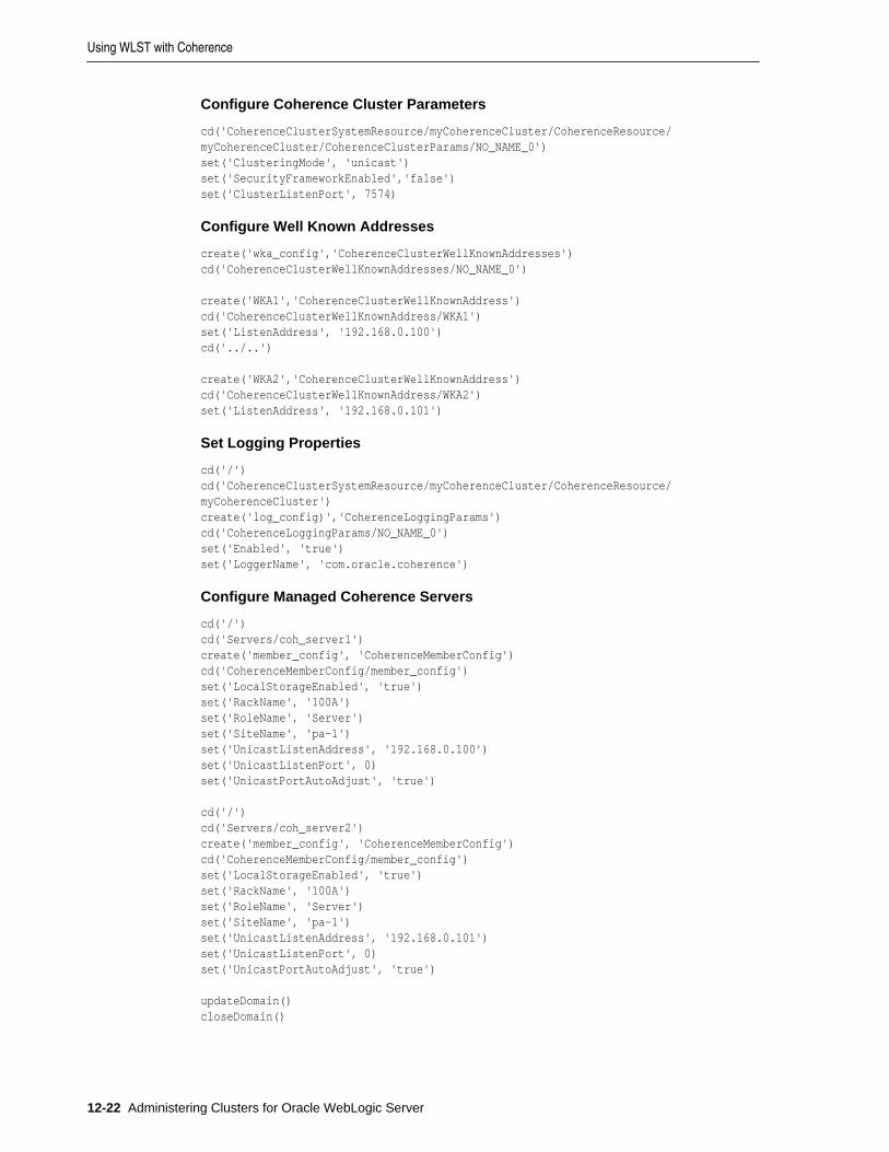
Configure Coherence Cluster Parameters
cd('CoherenceClusterSystemResource/myCoherenceCluster/CoherenceResource/myCoherenceCluster/CoherenceClusterParams/NO_NAME_0')set('ClusteringMode', 'unicast')set('SecurityFrameworkEnabled','false')set('ClusterListenPort', 7574)
Configure Well Known Addresses
create('wka_config','CoherenceClusterWellKnownAddresses')cd('CoherenceClusterWellKnownAddresses/NO_NAME_0') create('WKA1','CoherenceClusterWellKnownAddress')cd('CoherenceClusterWellKnownAddress/WKA1')set('ListenAddress', '192.168.0.100')cd('../..')
create('WKA2','CoherenceClusterWellKnownAddress')cd('CoherenceClusterWellKnownAddress/WKA2')set('ListenAddress', '192.168.0.101')
Set Logging Properties
cd('/')cd('CoherenceClusterSystemResource/myCoherenceCluster/CoherenceResource/myCoherenceCluster')create('log_config)','CoherenceLoggingParams')cd('CoherenceLoggingParams/NO_NAME_0')set('Enabled', 'true')set('LoggerName', 'com.oracle.coherence')
Configure Managed Coherence Servers
cd('/')cd('Servers/coh_server1')create('member_config', 'CoherenceMemberConfig')cd('CoherenceMemberConfig/member_config')set('LocalStorageEnabled', 'true')set('RackName', '100A')set('RoleName', 'Server')set('SiteName', 'pa-1')set('UnicastListenAddress', '192.168.0.100')set('UnicastListenPort', 0)set('UnicastPortAutoAdjust', 'true')
cd('/')cd('Servers/coh_server2')create('member_config', 'CoherenceMemberConfig')cd('CoherenceMemberConfig/member_config')set('LocalStorageEnabled', 'true')set('RackName', '100A')set('RoleName', 'Server')set('SiteName', 'pa-1')set('UnicastListenAddress', '192.168.0.101')set('UnicastListenPort', 0)set('UnicastPortAutoAdjust', 'true')
updateDomain()closeDomain()
Using WLST with Coherence
12-22 Administering Clusters for Oracle WebLogic Server
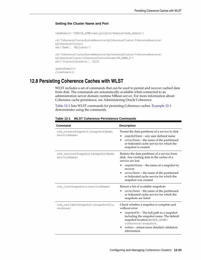
Setting the Cluster Name and Port
readDomain('/ORACLE_HOME/user_projects/domains/base_domain')
cd('CoherenceClusterSystemResource/myCoherenceCluster/CoherenceResource/myCoherenceCluster)set('Name', 'MyCluster')
cd('CoherenceClusterSystemResource/myCoherenceCluster/CoherenceResource/myCoherenceCluster/CoherenceClusterParams/NO_NAME_0')set('ClusterListenPort', 9123)
updateDomain()closeDomain()
12.8 Persisting Coherence Caches with WLSTWLST includes a set of commands that can be used to persist and recover cached datafrom disk. The commands are automatically available when connected to anadministration server domain runtime MBean server. For more information aboutCoherence cache persistence, see Administering Oracle Coherence.
Table 12-1 lists WLST commands for persisting Coherence caches. Example 12-1demonstrates using the commands.
Table 12-1 WLST Coherence Persistence Commands
Command Description
coh_createSnapshot(snapshotName,serviceName)
Persist the data partitions of a service to disk
• snapshotName – any user defined name• serviceName – the name of the partitioned
or federated cache service for which thesnapshot is created
coh_recoverSnapshot(snapshotName,serviceName)
Restore the data partitions of a service fromdisk. Any existing data in the caches of aservice are lost.
• snapshotName – the name of a snapshot torecover
• serviceName – the name of the partitionedor federated cache service for which thesnapshot was created
coh_listSnapshots(serviceName) Return a list of available snapshots
• serviceName – the name of the partitionedor federated cache service for which thesnapshots are listed
coh_validateSnapshot(snapshotDir,verbose)
Check whether a snapshot is complete andwithout error
• snapshotDir – The full path to a snapshotincluding the snapshot name. The defaultsnapshot location isUSER_HOME/coherence/snapshot.
• verbose – return more detailed validationinformation
Persisting Coherence Caches with WLST
Configuring and Managing Coherence Clusters 12-23
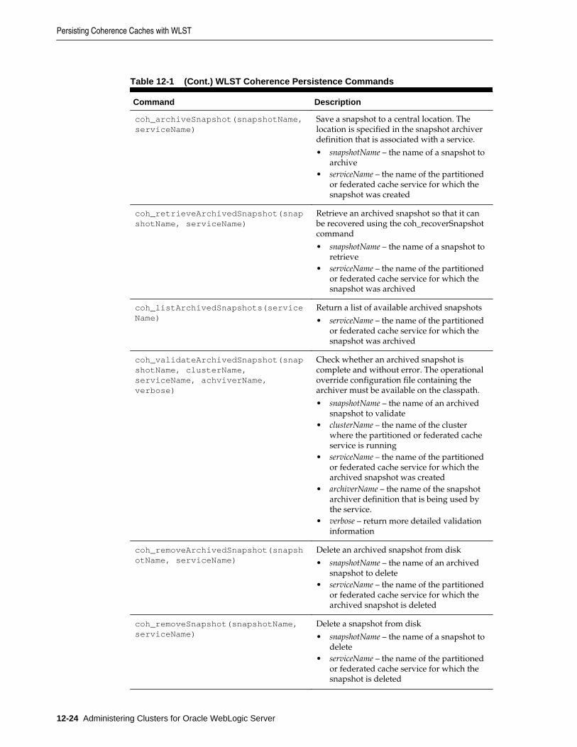
Table 12-1 (Cont.) WLST Coherence Persistence Commands
Command Description
coh_archiveSnapshot(snapshotName,serviceName)
Save a snapshot to a central location. Thelocation is specified in the snapshot archiverdefinition that is associated with a service.
• snapshotName – the name of a snapshot toarchive
• serviceName – the name of the partitionedor federated cache service for which thesnapshot was created
coh_retrieveArchivedSnapshot(snapshotName, serviceName)
Retrieve an archived snapshot so that it canbe recovered using the coh_recoverSnapshotcommand
• snapshotName – the name of a snapshot toretrieve
• serviceName – the name of the partitionedor federated cache service for which thesnapshot was archived
coh_listArchivedSnapshots(serviceName)
Return a list of available archived snapshots
• serviceName – the name of the partitionedor federated cache service for which thesnapshot was archived
coh_validateArchivedSnapshot(snapshotName, clusterName,serviceName, achviverName,verbose)
Check whether an archived snapshot iscomplete and without error. The operationaloverride configuration file containing thearchiver must be available on the classpath.
• snapshotName – the name of an archivedsnapshot to validate
• clusterName – the name of the clusterwhere the partitioned or federated cacheservice is running
• serviceName – the name of the partitionedor federated cache service for which thearchived snapshot was created
• archiverName – the name of the snapshotarchiver definition that is being used bythe service.
• verbose – return more detailed validationinformation
coh_removeArchivedSnapshot(snapshotName, serviceName)
Delete an archived snapshot from disk
• snapshotName – the name of an archivedsnapshot to delete
• serviceName – the name of the partitionedor federated cache service for which thearchived snapshot is deleted
coh_removeSnapshot(snapshotName,serviceName)
Delete a snapshot from disk
• snapshotName – the name of a snapshot todelete
• serviceName – the name of the partitionedor federated cache service for which thesnapshot is deleted
Persisting Coherence Caches with WLST
12-24 Administering Clusters for Oracle WebLogic Server
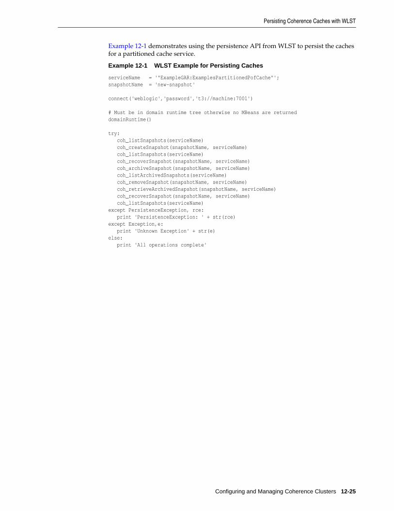
Example 12-1 demonstrates using the persistence API from WLST to persist the cachesfor a partitioned cache service.
Example 12-1 WLST Example for Persisting Caches
serviceName = '"ExampleGAR:ExamplesPartitionedPofCache"';snapshotName = 'new-snapshot' connect('weblogic','password','t3://machine:7001') # Must be in domain runtime tree otherwise no MBeans are returneddomainRuntime() try: coh_listSnapshots(serviceName) coh_createSnapshot(snapshotName, serviceName) coh_listSnapshots(serviceName) coh_recoverSnapshot(snapshotName, serviceName) coh_archiveSnapshot(snapshotName, serviceName) coh_listArchivedSnapshots(serviceName) coh_removeSnapshot(snapshotName, serviceName) coh_retrieveArchivedSnapshot(snapshotName, serviceName) coh_recoverSnapshot(snapshotName, serviceName) coh_listSnapshots(serviceName)except PersistenceException, rce: print 'PersistenceException: ' + str(rce)except Exception,e: print 'Unknown Exception' + str(e)else: print 'All operations complete'
Persisting Coherence Caches with WLST
Configuring and Managing Coherence Clusters 12-25

Persisting Coherence Caches with WLST
12-26 Administering Clusters for Oracle WebLogic Server
13Clustering Best Practices
This chapter recommends design and deployment practices that maximize thescalability, reliability, and performance of applications hosted by a WebLogic Servercluster.
This chapter includes the following sections:
• General Design Considerations
• Web Application Design Considerations
• EJB Design Considerations
• State Management in a Cluster
• Application Deployment Considerations
• Architecture Considerations
• Avoiding Problems
13.1 General Design ConsiderationsThe following sections describe general design guidelines for clustered applications.
13.1.1 Strive for SimplicityDistributed systems are complicated by nature. For a variety of reasons, makesimplicity a primary design goal. Minimize "moving parts" and do not distributealgorithms across multiple objects.
13.1.2 Minimize Remote CallsYou improve performance and reduce the effects of failures by minimizing remotecalls.
13.1.2.1 Session Facades Reduce Remote Calls
Avoid accessing EJB entity beans from client or servlet code. Instead, use a sessionbean, referred to as a facade, to contain complex interactions and reduce calls from Webapplications to RMI objects. When a client application accesses an entity bean directly,each getter method is a remote call. A session facade bean can access the entity beanlocally, collect the data in a structure, and return it by value.
13.1.2.2 Transfer Objects Reduce Remote Calls
EJBs consume significant system resources and network bandwidth to execute—theyare unlikely to be the appropriate implementation for every object in an application.
Clustering Best Practices 13-1
Use EJBs to model logical groupings of an information and associated business logic.For example, use an EJB to model a logical subset of the line items on an invoice—forinstance, items to which discounts, rebates, taxes, or other adjustments apply.
In contrast, an individual line item in an invoice is fine-grained—implementing it asan EJB wastes network resources. Implement objects that simply represents a set ofdata fields, which require only get and set functionality, as transfer objects.
Transfer objects (sometimes referred to as value objects or helper classes) are good formodeling entities that contain a group of attributes that are always accessed together.A transfer object is a serializable class within an EJB that groups related attributes,forming a composite value. This class is used as the return type of a remote businessmethod.
Clients receive instances of this class by calling coarse-grained business methods, andthen locally access the fine-grained values within the transfer object. Fetching multiplevalues in one server round-trip decreases network traffic and minimizes latency andserver resource usage.
13.1.2.3 Distributed Transactions Increase Remote Calls
Avoid transactions that span multiple server instances. Distributed transactions issueremote calls and consume network bandwidth and overhead for resourcecoordination.
13.2 Web Application Design ConsiderationsThe following sections describe design considerations for clustered servlets and JSPs.
13.2.1 Configure In-Memory ReplicationTo enable automatic failover of servlets and JSPs, session state must persist inmemory. For instructions to configure in-memory replication for HTTP session states,see Requirements for HTTP Session State Replication, and Configure In-MemoryHTTP Replication.
13.2.2 Design for IdempotenceFailures or impatient users can result in duplicate servlet requests. Design servlets totolerate duplicate requests.
13.2.3 Programming ConsiderationsSee Programming Considerations for Clustered Servlets and JSPs.
13.3 EJB Design ConsiderationsThe following sections describe design considerations for clustered RMI objects.
13.3.1 Design Idempotent MethodsIt is not always possible to determine when a server instance failed with respect to thework it was doing at the time of failure. For instance, if a server instance fails afterhandling a client request but before returning the response, there is no way to tell thatthe request was handled. A user that does not get a response retries, resulting in anadditional request.
Web Application Design Considerations
13-2 Administering Clusters for Oracle WebLogic Server

Failover for RMI objects requires that methods be idempotent. An idempotent methodis one that can be repeated with no negative side-effects.
13.3.2 Follow Usage and Configuration GuidelinesTable 13-1 summarizes usage and configuration guidelines for EJBs. For a list ofconfigurable cluster behaviors and resources and information on how to configurethem, see Table 13-2.
Table 13-1 EJB Types and Guidelines
Object Type Usage Configuration
EJBs of alltypes
Use EJBs to model logical groupings of an informationand associated business logic. See Transfer ObjectsReduce Remote Calls.
Configure clusterable homes. See Table 13-2.
Statefulsession beans
Recommended for high volume, heavy-writetransactions.
Remove stateful session beans when finished tominimize EJB container overhead. A stateful sessionbean instance is associated with a particular client, andremains in the container until explicitly removed by theclient, or removed by the container when it times out.Meanwhile, the container may passivate inactiveinstances to disk. This consumes overhead and canaffect performance.
Note: Although unlikely, the current state of a statefulsession bean can be lost. For example, if a clientcommits a transaction involving the bean and there is afailure of the primary server before the state change isreplicated, the client will fail over to the previously-stored state of the bean. If it is critical to preserve beanstate in all possible failover scenarios, use an entity EJBrather than a stateful session EJB.
Configure clusterable homes. See Table 13-2.
Configure in-memory replication forEJBs. See Table 13-2.
StatelessSession Beans
Scale better than stateful session beans which areinstantiated on a per client basis, and can multiply andconsume resources rapidly.
When a home creates a stateless bean, it returns areplica-aware stub that can route to any server wherethe bean is deployed. Because a stateless bean holds nostate on behalf of the client, the stub is free to route anycall to any server that hosts the bean.
Configure clusterable homes. See Table 13-2.
Configure Cluster Address. See Table13-2.
Configure methods to beidempotence (see Table 13-2) tosupport failover during method calls.(Failover is default behavior if failureoccurs between method calls.or if themethod fails to connect to a server).
The methods on stateless session beanhomes are automatically set to beidempotent. It is not necessary toexplicitly specify them as idempotent.
EJB Design Considerations
Clustering Best Practices 13-3
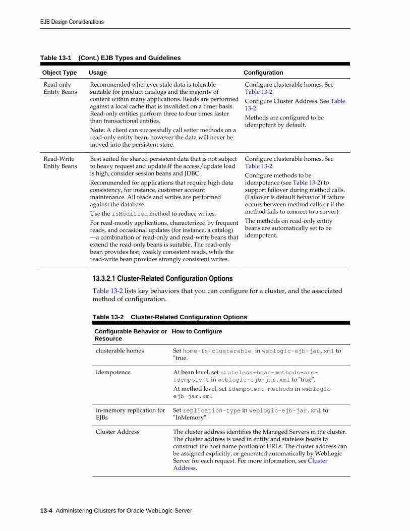
Table 13-1 (Cont.) EJB Types and Guidelines
Object Type Usage Configuration
Read-onlyEntity Beans
Recommended whenever stale data is tolerable—suitable for product catalogs and the majority ofcontent within many applications. Reads are performedagainst a local cache that is invalided on a timer basis.Read-only entities perform three to four times fasterthan transactional entities.
Note: A client can successfully call setter methods on aread-only entity bean, however the data will never bemoved into the persistent store.
Configure clusterable homes. See Table 13-2.
Configure Cluster Address. See Table13-2.
Methods are configured to beidempotent by default.
Read-WriteEntity Beans
Best suited for shared persistent data that is not subjectto heavy request and update.If the access/update loadis high, consider session beans and JDBC.
Recommended for applications that require high dataconsistency, for instance, customer accountmaintenance. All reads and writes are performedagainst the database.
Use the isModified method to reduce writes.
For read-mostly applications, characterized by frequentreads, and occasional updates (for instance, a catalog)—a combination of read-only and read-write beans thatextend the read-only beans is suitable. The read-onlybean provides fast, weakly consistent reads, while theread-write bean provides strongly consistent writes.
Configure clusterable homes. See Table 13-2.
Configure methods to beidempotence (see Table 13-2) tosupport failover during method calls.(Failover is default behavior if failureoccurs between method calls.or if themethod fails to connect to a server).
The methods on read-only entitybeans are automatically set to beidempotent.
13.3.2.1 Cluster-Related Configuration Options
Table 13-2 lists key behaviors that you can configure for a cluster, and the associatedmethod of configuration.
Table 13-2 Cluster-Related Configuration Options
Configurable Behavior orResource
How to Configure
clusterable homes Set home-is-clusterable in weblogic-ejb-jar.xml to"true.
idempotence At bean level, set stateless-bean-methods-are-idempotent in weblogic-ejb-jar.xml to "true".
At method level, set idempotent-methods in weblogic-ejb-jar.xml
in-memory replication forEJBs
Set replication-type in weblogic-ejb-jar.xml to"InMemory".
Cluster Address The cluster address identifies the Managed Servers in the cluster.The cluster address is used in entity and stateless beans toconstruct the host name portion of URLs. The cluster address canbe assigned explicitly, or generated automatically by WebLogicServer for each request. For more information, see ClusterAddress.
EJB Design Considerations
13-4 Administering Clusters for Oracle WebLogic Server
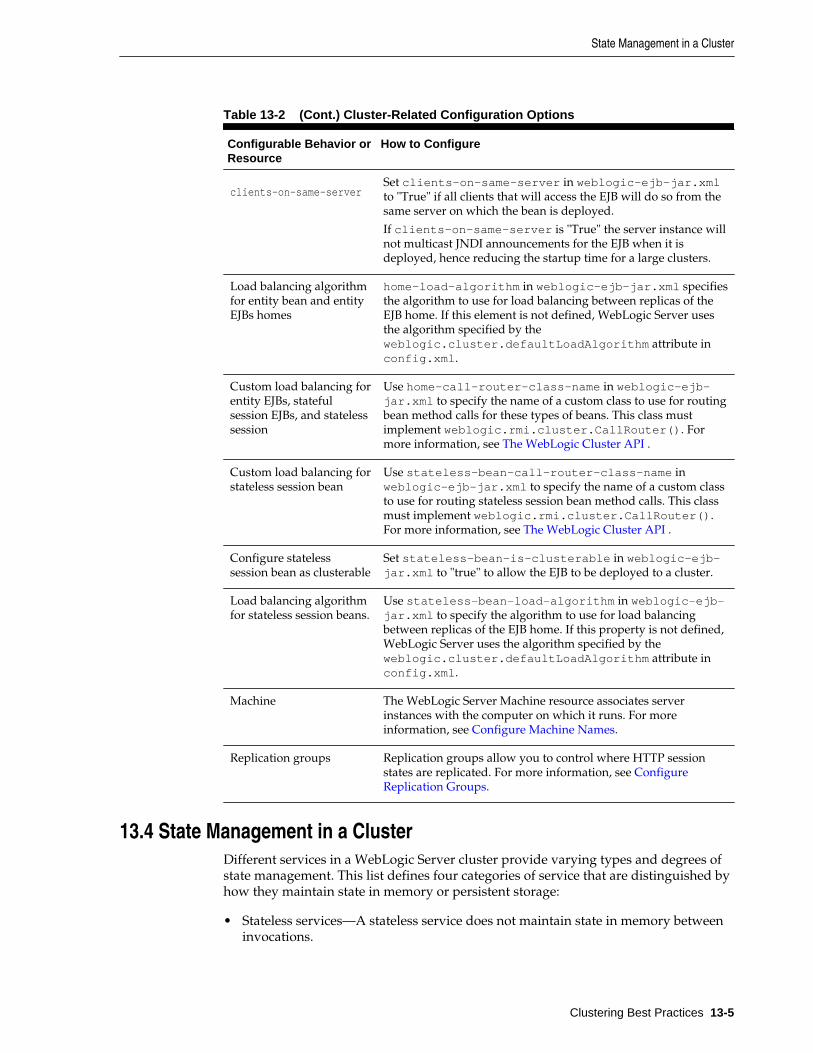
Table 13-2 (Cont.) Cluster-Related Configuration Options
Configurable Behavior orResource
How to Configure
clients-on-same-serverSet clients-on-same-server in weblogic-ejb-jar.xmlto "True" if all clients that will access the EJB will do so from thesame server on which the bean is deployed.
If clients-on-same-server is "True" the server instance willnot multicast JNDI announcements for the EJB when it isdeployed, hence reducing the startup time for a large clusters.
Load balancing algorithmfor entity bean and entityEJBs homes
home-load-algorithm in weblogic-ejb-jar.xml specifiesthe algorithm to use for load balancing between replicas of theEJB home. If this element is not defined, WebLogic Server usesthe algorithm specified by theweblogic.cluster.defaultLoadAlgorithm attribute inconfig.xml.
Custom load balancing forentity EJBs, statefulsession EJBs, and statelesssession
Use home-call-router-class-name in weblogic-ejb-jar.xml to specify the name of a custom class to use for routingbean method calls for these types of beans. This class mustimplement weblogic.rmi.cluster.CallRouter(). Formore information, see The WebLogic Cluster API .
Custom load balancing forstateless session bean
Use stateless-bean-call-router-class-name inweblogic-ejb-jar.xml to specify the name of a custom classto use for routing stateless session bean method calls. This classmust implement weblogic.rmi.cluster.CallRouter().For more information, see The WebLogic Cluster API .
Configure statelesssession bean as clusterable
Set stateless-bean-is-clusterable in weblogic-ejb-jar.xml to "true" to allow the EJB to be deployed to a cluster.
Load balancing algorithmfor stateless session beans.
Use stateless-bean-load-algorithm in weblogic-ejb-jar.xml to specify the algorithm to use for load balancingbetween replicas of the EJB home. If this property is not defined,WebLogic Server uses the algorithm specified by theweblogic.cluster.defaultLoadAlgorithm attribute inconfig.xml.
Machine The WebLogic Server Machine resource associates serverinstances with the computer on which it runs. For moreinformation, see Configure Machine Names.
Replication groups Replication groups allow you to control where HTTP sessionstates are replicated. For more information, see ConfigureReplication Groups.
13.4 State Management in a ClusterDifferent services in a WebLogic Server cluster provide varying types and degrees ofstate management. This list defines four categories of service that are distinguished byhow they maintain state in memory or persistent storage:
• Stateless services—A stateless service does not maintain state in memory betweeninvocations.
State Management in a Cluster
Clustering Best Practices 13-5

• Conversational services—A conversational service is dedicated to a particularclient for the duration of a session. During the session, it serves all requests fromthe client, and only requests from that client. Throughout a session there isgenerally state information that the application server must maintain betweenrequests. Conversational services typically maintain transient state in memory,which can be lost in the event of failure. If session state is written to a sharedpersistent store between invocations, the service is stateless. If persistent storage ofstate is not required, alternatives for improving performance and scalabilityinclude:
– Session state can be sent back and forth between the client and server under thecovers, again resulting in a stateless service. This approach is not always feasibleor desirable, particularly with large amounts of data.
– More commonly, session state may be retained in memory on the applicationserver between requests. Session state can be paged out from memory asnecessary to free up memory. Performance and scalability are still improved inthis case because updates are not individually written to disk and the data is notexpected to survive server failures.
• Cached services—A cached service maintains state in memory and uses it toprocess requests from multiple clients. Implementations of cached services vary inthe extent to which they keep the copies of cached data consistent with each otherand with associated data in the backing store.
• Singleton services—A singleton service is active on exactly one server in the clusterat a time and processes requests from multiple clients. A singleton service isgenerally backed by private, persistent data, which it caches in memory. It mayalso maintain transient state in memory, which is either regenerated or lost in theevent of failure. Upon failure, a singleton service must be restarted on the sameserver or migrated to a new server.
Table 13-3 summarizes how Java EE and WebLogic support each of these categories ofservice. Support for stateless and conversational services is described for two types ofclients:
• Loosely-coupled clients include browsers or Web Service clients that communicatewith the application server using standard protocols.
• Tightly-coupled clients are objects that run in the application tier or in the client-sideenvironment, and communicate with the application server using proprietaryprotocol.
State Management in a Cluster
13-6 Administering Clusters for Oracle WebLogic Server
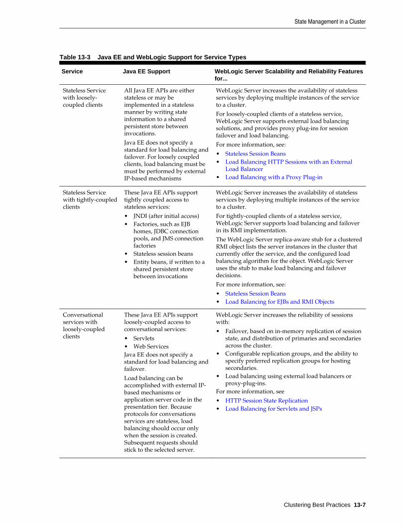
Table 13-3 Java EE and WebLogic Support for Service Types
Service Java EE Support WebLogic Server Scalability and Reliability Featuresfor...
Stateless Servicewith loosely-coupled clients
All Java EE APIs are eitherstateless or may beimplemented in a statelessmanner by writing stateinformation to a sharedpersistent store betweeninvocations.
Java EE does not specify astandard for load balancing andfailover. For loosely coupledclients, load balancing must bemust be performed by externalIP-based mechanisms
WebLogic Server increases the availability of statelessservices by deploying multiple instances of the serviceto a cluster.
For loosely-coupled clients of a stateless service,WebLogic Server supports external load balancingsolutions, and provides proxy plug-ins for sessionfailover and load balancing.
For more information, see:
• Stateless Session Beans• Load Balancing HTTP Sessions with an External
Load Balancer• Load Balancing with a Proxy Plug-in
Stateless Servicewith tightly-coupledclients
These Java EE APIs supporttightly coupled access tostateless services:
• JNDI (after initial access)• Factories, such as EJB
homes, JDBC connectionpools, and JMS connectionfactories
• Stateless session beans• Entity beans, if written to a
shared persistent storebetween invocations
WebLogic Server increases the availability of statelessservices by deploying multiple instances of the serviceto a cluster.
For tightly-coupled clients of a stateless service,WebLogic Server supports load balancing and failoverin its RMI implementation.
The WebLogic Server replica-aware stub for a clusteredRMI object lists the server instances in the cluster thatcurrently offer the service, and the configured loadbalancing algorithm for the object. WebLogic Serveruses the stub to make load balancing and failoverdecisions.
For more information, see:
• Stateless Session Beans• Load Balancing for EJBs and RMI Objects
Conversationalservices withloosely-coupledclients
These Java EE APIs supportloosely-coupled access toconversational services:
• Servlets• Web ServicesJava EE does not specify astandard for load balancing andfailover.
Load balancing can beaccomplished with external IP-based mechanisms orapplication server code in thepresentation tier. Becauseprotocols for conversationsservices are stateless, loadbalancing should occur onlywhen the session is created.Subsequent requests shouldstick to the selected server.
WebLogic Server increases the reliability of sessionswith:
• Failover, based on in-memory replication of sessionstate, and distribution of primaries and secondariesacross the cluster.
• Configurable replication groups, and the ability tospecify preferred replication groups for hostingsecondaries.
• Load balancing using external load balancers orproxy-plug-ins.
For more information, see
• HTTP Session State Replication• Load Balancing for Servlets and JSPs
State Management in a Cluster
Clustering Best Practices 13-7
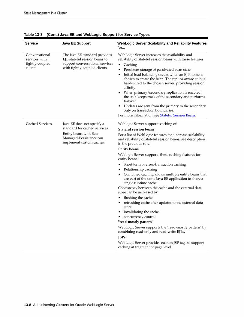
Table 13-3 (Cont.) Java EE and WebLogic Support for Service Types
Service Java EE Support WebLogic Server Scalability and Reliability Featuresfor...
Conversationalservices withtightly-coupledclients
The Java EE standard providesEJB stateful session beans tosupport conversational serviceswith tightly-coupled clients.
WebLogic Server increases the availability andreliability of stateful session beans with these features:
• Caching• Persistent storage of passivated bean state.• Initial load balancing occurs when an EJB home is
chosen to create the bean. The replica-aware stub ishard-wired to the chosen server, providing sessionaffinity.
• When primary/secondary replication is enabled,the stub keeps track of the secondary and performsfailover.
• Updates are sent from the primary to the secondaryonly on transaction boundaries.
For more information, see Stateful Session Beans.
Cached Services Java EE does not specify astandard for cached services.
Entity beans with Bean-Managed-Persistence canimplement custom caches.
Weblogic Server supports caching of:
Stateful session beans
For a list of WebLogic features that increase scalabilityand reliability of stateful session beans, see descriptionin the previous row.
Entity beans
Weblogic Server supports these caching features forentity beans.
• Short term or cross-transaction caching• Relationship caching• Combined caching allows multiple entity beans that
are part of the same Java EE application to share asingle runtime cache
Consistency between the cache and the external datastore can be increased by:
• flushing the cache• refreshing cache after updates to the external data
store• invalidating the cache• concurrency control"read-mostly pattern"
WebLogic Server supports the "read-mostly pattern" bycombining read-only and read-write EJBs.
JSPs
WebLogic Server provides custom JSP tags to supportcaching at fragment or page level.
State Management in a Cluster
13-8 Administering Clusters for Oracle WebLogic Server
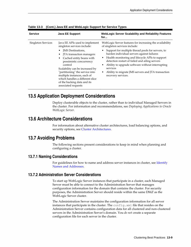
Table 13-3 (Cont.) Java EE and WebLogic Support for Service Types
Service Java EE Support WebLogic Server Scalability and Reliability Featuresfor...
Singleton Services Java EE APIs used to implementsingleton services include:
• JMS Destinations,• JTA transaction managers• Cached entity beans with
pessimistic concurrencycontrol
Scalability can be increased by"partitioning" the service intomultiple instances, each ofwhich handles a different sliceof the backing data and itsassociated requests
WebLogic Server features for increasing the availabilityof singleton services include:
• Support for multiple thread pools for servers, toharden individual servers against failures
• Health monitoring and lifecycle APIs to supportdetection restart of failed and ailing servers
• Ability to upgrade software without interruptingservices
• Ability to migrate JMS servers and JTA transactionrecovery services.
13.5 Application Deployment ConsiderationsDeploy clusterable objects to the cluster, rather than to individual Managed Servers inthe cluster. For information and recommendations, see Deploying Applications to OracleWebLogic Server.
13.6 Architecture ConsiderationsFor information about alternative cluster architectures, load balancing options, andsecurity options, see Cluster Architectures.
13.7 Avoiding ProblemsThe following sections present considerations to keep in mind when planning andconfiguring a cluster.
13.7.1 Naming ConsiderationsFor guidelines for how to name and address server instances in cluster, see IdentifyNames and Addresses.
13.7.2 Administration Server ConsiderationsTo start up WebLogic Server instances that participate in a cluster, each ManagedServer must be able to connect to the Administration Server that managesconfiguration information for the domain that contains the cluster. For securitypurposes, the Administration Server should reside within the same DMZ as theWebLogic Server cluster.
The Administration Server maintains the configuration information for all serverinstances that participate in the cluster. The config.xml file that resides on theAdministration Server contains configuration data for all clustered and non-clusteredservers in the Administration Server's domain. You do not create a separateconfiguration file for each server in the cluster.
Application Deployment Considerations
Clustering Best Practices 13-9
The Administration Server must be available in order for clustered WebLogic Serverinstances to start up. Note, however, that once a cluster is running, a failure of theAdministration Server does not affect ongoing cluster operation.
The Administration Server should not participate in a cluster. The AdministrationServer should be dedicated to the process of administering servers: maintainingconfiguration data, starting and shutting down servers, and deploying andundeploying applications. If the Administration Server also handles client requests,there is a risk of delays in accomplishing administration tasks.
There is no benefit in clustering an Administration Server; the administrative objectsare not clusterable, and will not failover to another cluster member if theadministrative server fails. Deploying applications on an Administration Server canreduce the stability of the server and the administrative functions it provides. If anapplication you deploy on the Administration Server behaves unexpectedly, it couldinterrupt operation of the Administration Server.
For these reasons, make sure that the Administration Server's IP address is notincluded in the cluster-wide DNS name.
13.7.3 Firewall ConsiderationsIf your configuration includes a firewall, locate your proxy server or load-balancer inyour DMZ, and the cluster, both Web and EJB containers, behind the firewall. Webcontainers in DMZ are not recommended. See Basic Firewall for Proxy Architectures.
If you place a firewall between the servlet cluster and object cluster in a multi-tierarchitecture, bind all servers in the object cluster to public DNS names, rather than IPaddresses. Binding those servers with IP addresses can cause address translationproblems and prevent the servlet cluster from accessing individual server instances.
If the internal and external DNS names of a WebLogic Server instance are notidentical, use the ExternalDNSName attribute for the server instance to define theserver's external DNS name. Outside the firewall the ExternalDNSName shouldtranslate to external IP address of the server. Set this attribute in the WebLogic ServerAdministration Console using the Servers > Configuration > General page. SeeServers > Configuration > General in Oracle WebLogic Server Administration ConsoleOnline Help.
In any cluster architecture that utilizes one or more firewalls, it is critical to identify allWebLogic Server instances using publicly-available DNS names, rather than IPaddresses. Using DNS names avoids problems associated with address translationpolicies used to mask internal IP addresses from untrusted clients.
Note:
Use of ExternalDNSName is required for configurations in which a firewall isperforming Network Address Translation, unless clients are accessingWebLogic Server using t3 and the default channel. For instance,ExternalDNSName is required for configurations in which a firewall isperforming Network Address Translation, and clients are accessing WebLogicServer using HTTP via a proxy plug-in.
Figure 13-1 describes the potential problem with using IP addresses to identifyWebLogic Server instances. In this figure, the firewall translates external IP requestsfor the subnet "xxx" to internal IP addresses having the subnet "yyy."
Avoiding Problems
13-10 Administering Clusters for Oracle WebLogic Server
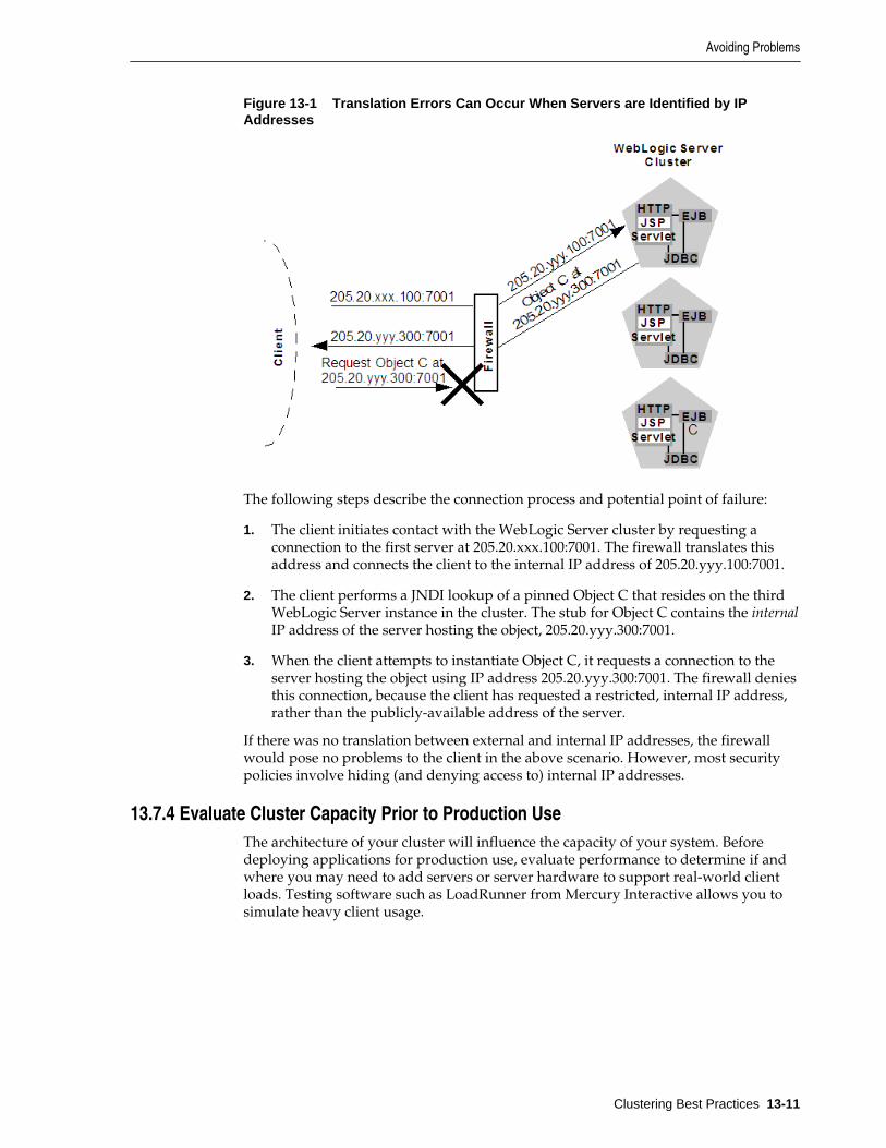
Figure 13-1 Translation Errors Can Occur When Servers are Identified by IPAddresses
The following steps describe the connection process and potential point of failure:
1. The client initiates contact with the WebLogic Server cluster by requesting aconnection to the first server at 205.20.xxx.100:7001. The firewall translates thisaddress and connects the client to the internal IP address of 205.20.yyy.100:7001.
2. The client performs a JNDI lookup of a pinned Object C that resides on the thirdWebLogic Server instance in the cluster. The stub for Object C contains the internalIP address of the server hosting the object, 205.20.yyy.300:7001.
3. When the client attempts to instantiate Object C, it requests a connection to theserver hosting the object using IP address 205.20.yyy.300:7001. The firewall deniesthis connection, because the client has requested a restricted, internal IP address,rather than the publicly-available address of the server.
If there was no translation between external and internal IP addresses, the firewallwould pose no problems to the client in the above scenario. However, most securitypolicies involve hiding (and denying access to) internal IP addresses.
13.7.4 Evaluate Cluster Capacity Prior to Production UseThe architecture of your cluster will influence the capacity of your system. Beforedeploying applications for production use, evaluate performance to determine if andwhere you may need to add servers or server hardware to support real-world clientloads. Testing software such as LoadRunner from Mercury Interactive allows you tosimulate heavy client usage.
Avoiding Problems
Clustering Best Practices 13-11

Avoiding Problems
13-12 Administering Clusters for Oracle WebLogic Server
14Troubleshooting Common Problems
This chapter provides guidelines on how to prevent cluster problems or troubleshootthem if they do occur.
For information about troubleshooting IP multicast configuration problems, see Troubleshooting Multicast Configuration.
This chapter includes the following sections:
• Before You Start the Cluster
• After You Start the Cluster
14.1 Before You Start the ClusterYou can do a number of things to help prevent problems before you boot the cluster.
14.1.1 Check the Server Version NumbersAll servers in the cluster should be at the same maintenance level (the same major andminor version number, the same Patch Set number, the same Patch Set Updatenumber, and the same Interim/One-off Patches) during steady-state operation.Rolling upgrade (applying maintenance to servers sequentially within a cluster) issupported in WebLogic Server:
• for applying Interim/One-off Patches
• for applying Patch Set Updates (PSUs)
• for applying WebLogic Server 10.3.x Patch Sets, for example, performing a rollingupgrade from WebLogic Server 10.3.5 to 10.3.6
The cluster's Administration Server is typically not configured as a cluster member,but it should generally run at the same maintenance level as the Managed Servers.There may be situations where the Administration Server is managing multipleclusters within a single domain, which may be at different maintenance levels. In thiscase, the Administration Server should be at the highest maintenance level of theManaged Servers within the domain.
14.1.2 Check the Multicast AddressA problem with the multicast address is one of the most common reasons a clusterdoes not start or a server fails to join a cluster.
A multicast address is required for each cluster. The multicast address can be an IPnumber between 224.0.0.0 and 239.255.255.255, or a host name with an IP addresswithin that range.
Troubleshooting Common Problems 14-1
You can check a cluster's multicast address and port on its Configuration > Multicastpage in the WebLogic Server Administration Console.
For each cluster on a network, the combination of multicast address and port must beunique. If two clusters on a network use the same multicast address, they should usedifferent ports. If the clusters use different multicast addresses, they can use the sameport or accept the default port, 7001.
Before booting the cluster, make sure the cluster's multicast address and port arecorrect and do not conflict with the multicast address and port of any other clusters onthe network.
The errors you are most likely to see if the multicast address is bad are:
Unable to create a multicast socket for clusteringMulticast socket send errorMulticast socket receive error
14.1.3 Check the CLASSPATH ValueMake sure the value of CLASSPATH is the same on all Managed Servers in the cluster.CLASSPATH is set by the setEnv script, which you run before you runstartManagedWebLogic to start the Managed Servers.
By default, setEnv sets this value for CLASSPATH (as represented on Windowssystems):
set WL_HOME=C:\bea\wlserver_10.00set JAVA_HOME=C:\bea\jdk131..set CLASSPATH=%JAVA_HOME%\lib\tools.jar; %WL_HOME%\server\lib\weblogic_sp.jar; %WL_HOME%\server\lib\weblogic.jar; %CLASSPATH%
If you change the value of CLASSPATH on one Managed Server, or change howsetEnv sets CLASSPATH, you must change it on all Managed Servers in the cluster.
14.2 After You Start the ClusterAfter you start a cluster, do the following to troubleshoot problems.
14.2.1 Check Your CommandsIf the cluster fails to start, or a server fails to join the cluster, the first step is to checkany commands you have entered, such as startManagedWebLogic or a javainterpreter command, for errors and misspellings.
14.2.2 Generate a Log FileBefore contacting Oracle for help with cluster-related problems, collect diagnosticinformation. The most important information is a log file with multiple thread dumpsfrom a Managed Server. The log file is especially important for diagnosing clusterfreezes and deadlocks.
Remember: a log file that contains multiple thread dumps is a prerequisite for diagnosingyour problem.
1. Stop the server.
After You Start the Cluster
14-2 Administering Clusters for Oracle WebLogic Server
2. Remove or back up any log files you currently have. You should create a new logfile each time you boot a server, rather than appending to an existing log file.
3. Start the server with this command, which turns on verbose garbage collection andredirects both the standard error and standard output to a log file:
% java -ms64m -mx64m -verbose:gc -classpath $CLASSPATH -Dweblogic.domain=mydomain -Dweblogic.Name=clusterServer1 -Djava.security.policy==$WL_HOME/lib/weblogic.policy -Dweblogic.admin.host=192.168.0.101:7001 weblogic.Server >> logfile.txt
Redirecting both standard error and standard output places thread dumpinformation in the proper context with server informational and error messagesand provides a more useful log.
4. Continue running the cluster until you have reproduced the problem.
5. If a server hangs, use kill -3 or <Ctrl>-<Break> to create the necessary threaddumps to diagnose your problem. Make sure to do this several times on eachserver, spaced about 5-10 seconds apart, to help diagnose deadlocks.
6. Compress the log file using a UNIX utility:
% tar czf logfile.tar logfile.txt
- or zip it using a Windows utility.
7. Attach the compressed log file to an e-mail to your Oracle Support representative.Do not cut and paste the log file into the body of an e-mail.
14.2.2.1 Getting an Oracle HotSpot VM Thread Dump
If you use the Oracle HotSpot VM, use one of the following methods to generate athread dump:
• Use the WLST threadDUMP command.
• Use the jstack utility.
• If you are using the Oracle HotSpot VM under Linux, use Kill -3 PID, wherePID is the root of the process tree.
To obtain the root PID, perform a:
ps -efHl | grep 'java' **. **
using a grep argument that is a string that will be found in the process stack thatmatches the server startup command. The first PID reported will be the rootprocess, assuming that the ps command has not been piped to another routine.
Under Linux, each execute thread appears as a separate process under the Linuxprocess stack. To use Kill -3 on Linux you supply must match PID of the mainWebLogic execute thread, otherwise no thread dump will be produced.
• If you are using the Oracle HotSpot VM under Windows, you can use the Ctrl-Break command on the application console to generate a thread dump.
After You Start the Cluster
Troubleshooting Common Problems 14-3
14.2.3 Check Garbage CollectionIf you are experiencing cluster problems, you should also check the garbage collectionon the Managed Servers. If garbage collection is taking too long, the servers will not beable to make the frequent heartbeat signals that tell the other cluster members they arerunning and available.
If garbage collection (either first or second generation) is taking 10 or more seconds,you need to tune heap allocation (the msmx parameter) on your system.
14.2.4 Run utils.MulticastTestYou can verify that multicast is working by running utils.MulticastTest fromone of the Managed Servers. See Using the Oracle WebLogic Server Java Utilities inCommand Reference for Oracle WebLogic Server.
After You Start the Cluster
14-4 Administering Clusters for Oracle WebLogic Server
15Troubleshooting Multicast Configuration
This chapter provides suggestions for troubleshooting IP multicast configurationproblems. Using IP multicasting, WebLogic Server instances in a cluster can share asingle IP address and port number. This capability enables all members of a cluster tobe treated as a single entity and enables members of the cluster to communicateamong themselves.
This chapter includes the following sections:
• Verifying Multicast Address and Port Configuration
• Identifying Network Configuration Problems
• Using the MulticastTest Utility
• Tuning Multicast Features
• Debugging Multicast
• Miscellaneous Issues
• Other Resources for Troubleshooting Multicast Configuration
For general information on using and configuring multicast within a cluster, see Cluster Configuration and config.xml.
For information on configuring a multicast address from the Console, see Clusters:Configuration: Multicast in the Oracle WebLogic Server Administration Console OnlineHelp.
For general cluster troubleshooting suggestions, see Troubleshooting CommonProblems.
15.1 Verifying Multicast Address and Port ConfigurationThe first step in troubleshooting multicast problems is to verify that you haveconfigured the multicast address and port correctly. A multicast address must becorrectly configured for each cluster.
Multicast address and port configuration problems are among the most commonreasons why a cluster does not start or a server fails to join a cluster. The followingconsiderations apply to multicast addresses:
• The multicast address must be an IP address between 224.0.0.0 and 239.255.255.255or a host name with an IP address in this range.
• The default multicast address used by WebLogic Server is 239.192.0.0.
• Do not use any x.0.0.1 multicast address where x is between 0 and 9, inclusive.
Troubleshooting Multicast Configuration 15-1
15.1.1 Possible ErrorsThe following types of errors commonly occur due to multicast configurationproblems:
• Unable to create a multicast socket for clustering
• Multicast socket send error
• Multicast socket receive error
15.1.2 Checking the Multicast Address and PortTo check the multicast address and port, do one of the following:
• Check the cluster multicast address and port through the WebLogic ServerAdministration Console.
• Check the multicast information of the <cluster> element in config.xml.
15.2 Identifying Network Configuration ProblemsAfter you verify that the multicast address and port are configured correctly,determine whether network problems are interfering with multicast communication.
15.2.1 Physical ConnectionsEnsure that no physical problems exist in your network.
• Verify the network connection for each machine that hosts servers within thecluster.
• Verify that all components of the network, including routers and DNS servers, areconnected and functioning correctly.
15.2.2 Address ConflictsAddress conflicts within a network can disrupt multicast communications.
• Use the netstat utility to verify that no other network resources are using thecluster multicast address.
• Verify that each machine has a unique IP address.
15.2.3 nsswitch.conf Settings on UNIX SystemsOn UNIX systems, you may encounter the UnkownHostExceptions error. This errorcan occur at random times even when the server is not under a heavy load.Check /etc/nsswitch.conf and change the order to 'files,DNS,NIS' to avoidthis error.
For more information, see the nsswitch.conf man page for your system.
15.3 Using the MulticastTest UtilityAfter you verify that the multicast address and port are configured correctly and thereare no physical or configuration problems with your network, you can use
Identifying Network Configuration Problems
15-2 Administering Clusters for Oracle WebLogic Server
utils.MulticastTest to verify that multicast is working and to determine ifunwanted traffic is occurring between different clusters.
For instructions on using the MulticastTest utility, see MulticastTest in Using theOracle WebLogic Server Java Utilities in Command Reference for Oracle WebLogic Server.
If MulticastTest fails and the machine is multihomed, ensure that the primary addressis being used. See Multicast and Multihomed Machines.
Note:
You should set -Djava.net.preferIPv4Stack=true when specifying anIPv4 format address for the multicast address on Linux machines runningdual IPv4/IPv6 stacks.
15.4 Tuning Multicast FeaturesThe following sections describe how to tune various features of WebLogic Server towork with multicasting.
15.4.1 Multicast TimeoutsMulticast timeouts can occur during a Network Interface Card (NIC) failover.Timeouts can result in an error message like the following:
<Error><Cluster><Multicast socket receive error:java.io.InterruptedIOException: Receive timed out>
When this error occurs, you can:
• Disable the NIC failover.
• Disable the igmp snooping switch. This switch is part of the Internet GroupManagement Protocol (IGMP) and is used to prevent multicast flood problems onthe managed switch.
• On Windows 2000, check the IGMP level to ensure that multicast packets aresupported.
• Set the Multicast Time-To-Live to the following:
MulticastTTL=32
For more information, see Configure Multicast Time-To-Live (TTL).
15.4.2 Cluster HeartbeatsEach WebLogic Server instance in a cluster uses multicast to broadcast regularheartbeat messages that advertise its availability. By monitoring heartbeat messages,server instances in a cluster determine when a server instance has failed.
The following sections describe possible solutions when cluster heartbeat problemsoccur.
15.4.2.1 Multicast Send Delay
Multicast Send Delay specifies the amount of time the server waits to send messagefragments through multicast. This delay helps to avoid OS-level buffer overflow. This
Tuning Multicast Features
Troubleshooting Multicast Configuration 15-3
can be set via the MulticastSendDelay attribute of the Cluster MBean. For moreinformation, see the MBean Reference for Oracle WebLogic Server.
15.4.2.2 Operating System Parameters
If problems still occur after setting the Multicast Send Delay, you may need to set thefollowing operating system parameters related to UDP settings:
• xdp_xmit_hiwat
• udp_recv_hiwat
If these parameters are set to a lower value (8K for example) there may be a problem ifthe multicast packet size is set to the maximum allowed (32K). Try setting theseparameters to 64K.
15.4.3 Multicast StormsA multicast storm is the repeated transmission of multicast packets on a network.Multicast storms can stress the network and attached stations, potentially causing end-stations to hang or fail.
Increasing the size of the multicast buffers can improve the rate at whichannouncements are transmitted and received, and prevent multicast storms. See Configure Multicast Buffer Size.
15.4.4 Multicast and Multihomed MachinesThe following considerations apply when using multicast in a multihomedenvironment:
• Ensure that you have configured a UnixMachine instance from the WebLogicServer Administration Console and have specified an InterfaceAddress foreach server instance to handle multicast traffic.
• Run /usr/sbin/ifconfig -a to check the MAC address of each machine in themultihomed environment. Ensure that each machine has a unique MAC address. Ifmachines use the same MAC address, this can cause multicast problems.
15.4.5 Multicast in Different SubnetsIf multicast problems occur when cluster members are in different subnets you shouldconfigure Multicast-Time-To-Live. The value of the Multicast Time-To-Live (TTL)parameter for the cluster must be high enough to ensure that routers do not discardmulticast packets before they reach their final destination.
The Multicast TTL parameter sets the number of network hops a multicast messagemakes before the packet can be discarded. Configuring the Multicast TTL parameterappropriately reduces the risk of losing the multicast messages that are transmittedamong server instances in the cluster.
For more information, see Configure Multicast Time-To-Live (TTL).
15.5 Debugging MulticastIf you are still having problems with the multicast address after performing thetroubleshooting tips above, gather debugging information for multicast.
Debugging Multicast
15-4 Administering Clusters for Oracle WebLogic Server
15.5.1 Debugging UtilitiesThe following utilities can help you debug multicast configuration problems.
15.5.1.1 MulticastMonitor
MulticastMontior is a standalone Java command line utility that monitors multicasttraffic on a specific multicast address and port. The syntax for this command is:
java weblogic.cluster.MulticastMonitor <multicast_address> <multicast_port> <domain_name> <cluster_name>
15.5.1.2 MulticastTest
The MulticastTest utility helps you debug multicast problems when you configure aWebLogic cluster. The utility sends out multicast packets and returns informationabout how effectively multicast is working on your network.
15.5.2 Debugging FlagsThe following debug flags are specific to multicast:
• DebugCluster
• DebugClusterHeartBeats
• DebugClusterFragments
15.5.2.1 Setting Debug Flags on the Command Line
Set these flags from the command line during server startup by adding the followingoptions:
• -Dweblogic.debug.DebugCluster=true
• -Dweblogic.debug.DebugClusterHeartBeats=true
• -Dweblogic.debug.DebugClusterFragments=true
15.5.2.2 Setting Debug Attributes Using WLST
Set debug attributes using these WLST commands:
connect()edit()startEdit()servers=cmo.getServers()for s in servers: d=s.getServerDebug() d.setDebugCluster(true)activate()
15.6 Miscellaneous IssuesThe following sections describe miscellaneous multicast issues you may encounter.
Miscellaneous Issues
Troubleshooting Multicast Configuration 15-5
15.6.1 Multicast on AIXAIX version 5.1 does not support IPv4 mapped multicast addresses. If you are usingan IPv4 multicast address, you cannot join a multicast group even if you are switchingto IPv6. When running MulticastTest on AIX, use the order on the command linespecified in the following example:
java -Djava.net.preferIPv4Stack=true utils.Multicast <options>
Additionally, verify the following settings on AIX to properly configure clusteroperations:
• Set the MTU size to 1500 by executing the following command and rebooting themachine:
chdev -1 lo0 -a mtu=1500 -P
• Ensure that the following has been added to /etc/netsvc.conf:
hosts=local,bind4
This line is required to ensure that only IPv4 addresses are sent to name servicesfor IP resolution.
15.6.2 File Descriptor ProblemsDepending on the operating system, there may be problems with the number of filedescriptors open. On UNIX, you can use loses to determine how many files on disk aprocess has open. If a problem occurs, you may need to increase the number of filedescriptors on the machine.
15.7 Other Resources for Troubleshooting Multicast ConfigurationThe following resources may be helpful in resolving multicast problems:
• Oracle Fusion Middleware Release Notes for Microsoft Windows
• Oracle Support: https://support.oracle.com/
• Oracle Forums: http://forums.oracle.com/
Other Resources for Troubleshooting Multicast Configuration
15-6 Administering Clusters for Oracle WebLogic Server
AThe WebLogic Cluster API
This appendix describes how to use the WebLogic Cluster API.
The appendix includes the following sections:
• How to Use the API
• Custom Call Routing and Collocation Optimization
A.1 How to Use the APIThe WebLogic Cluster public API is contained in a single interface,weblogic.rmi.cluster.CallRouter.
Class java.lang.Object Interface weblogic.rmi.cluster.CallRouter (extends java.io.Serializable)
A class implementing this interface must be provided to the RMI compiler (rmic) toenable parameter-based routing. Run rmic on the service implementation using theseoptions (to be entered on one line):
$ java weblogic.rmic -clusterable -callRouter <callRouterClass> <remoteObjectClass>
The call router is called by the clusterable stub each time a remote method is invoked.The router is responsible for returning the name of the server to which the call shouldbe routed.
Each server in the cluster is uniquely identified by its name as defined with theWebLogic Server Console. These are the names that the method router must use foridentifying servers.
Example: Consider the ExampleImpl class which implements a remote interfaceExample, with one method foo:
public class ExampleImpl implements Example { public void foo(String arg) { return arg; }}
This CallRouter implementation ExampleRouter ensures that all foo calls with'arg' < "n" go to server1 (or server3 if server1 is unreachable) and that all calls with'arg' >= "n" go to server2 (or server3 if server2 is unreachable).
public class ExampleRouter implements CallRouter { private static final String[] aToM = { "server1", "server3" }; private static final String[] nToZ = { "server2", "server3" };
public String[] getServerList(Method m, Object[] params) { if (m.GetName().equals("foo")) { if (((String)params[0]).charAt(0) < 'n') {
The WebLogic Cluster API A-1
return aToM; } else { return nToZ; } } else { return null; } }}
This rmic call associates the ExampleRouter with ExampleImpl to enableparameter-based routing:
$ rmic -clusterable -callRouter ExampleRouter ExampleImpl
A.2 Custom Call Routing and Collocation OptimizationIf a replica is available on the same server instance as the object calling it, the call willnot be load balanced, because it is more efficient to use the local replica. For moreinformation, see Optimization for Collocated Objects.
Custom Call Routing and Collocation Optimization
A-2 Administering Clusters for Oracle WebLogic Server
BConfiguring BIG-IP Hardware with Clusters
For detailed setup and administration instructions for configuring an F5 BIG-IPcontroller to operate with a WebLogic Server cluster, refer to the F5 productdocumentation described at http://www.f5.com/.
For information about how WebLogic Server works with external load balancers, see Load Balancing HTTP Sessions with an External Load Balancer.
Configuring BIG-IP Hardware with Clusters B-1

B-2 Administering Clusters for Oracle WebLogic Server
CConfiguring F5 Load Balancers for
MAN/WAN Failover
This appendix describes how to configure F5 hardware load balancers.
WebLogic Server provides failover within MAN and WAN networks. This featureprovides more reliability by allowing failover to occur across a larger geographic area.It also provides failover across multiple WebLogic Server domains.
To provide failover within a MAN/WAN environment, you must use hardware loadbalancers. This document outlines the procedures for configuring F5 hardware loadbalancers to work with WebLogic Server.
For information on configuring WebLogic Server to use MAN/WAN, see Session StateReplication Across Clusters in a MAN/WAN. For information on configuring F5hardware load balancers, see http://www.f5.com.
This appendix includes the following sections:
• Requirements
• Configure Local Load Balancers
• Configure the 3-DNS Global Hardware Load Balancer
• Configuring WebLogic Server Components
C.1 RequirementsBefore performing the procedures described in this appendix, you must haveperformed the following:
• Installed and configured your WebLogic Server environment. This includescreating and configuring clusters and Managed Servers.
• Installed and configured at least one F5 3-DNS global load balancer and at leasttwo F5 BIG-IP local load balancers. This is the minimum hardware requirement forfailover in a MAN/WAN environment
• Ensured that your network and DNS are configured correctly
Once these requirements are met, perform the following procedures to configure yourload balancers to work within a MAN/WAN environment.
C.2 Configure Local Load BalancersThis section describes the procedures for configuring F5 local load balancers to workwith WebLogic Server in a MAN/WAN environment.
Configuring F5 Load Balancers for MAN/WAN Failover C-1
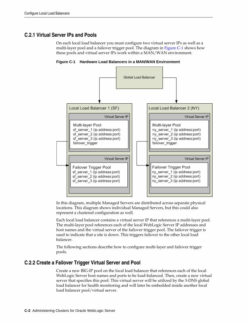
C.2.1 Virtual Server IPs and PoolsOn each local load balancer you must configure two virtual server IPs as well as amulti-layer pool and a failover trigger pool. The diagram in Figure C-1 shows howthese pools and virtual server IPs work within a MAN/WAN environment.
Figure C-1 Hardware Load Balancers in a MAN/WAN Environment
In this diagram, multiple Managed Servers are distributed across separate physicallocations. This diagram shows individual Managed Servers, but this could alsorepresent a clustered configuration as well.
Each local load balancer contains a virtual server IP that references a multi-layer pool.The multi-layer pool references each of the local WebLogic Server IP addresses andhost names and the virtual server of the failover trigger pool. The failover trigger isused to indicate that a site is down. This triggers failover to the other local loadbalancer.
The following sections describe how to configure multi-layer and failover triggerpools.
C.2.2 Create a Failover Trigger Virtual Server and PoolCreate a new BIG-IP pool on the local load balancer that references each of the localWebLogic Server host names and ports to be load-balanced. Then, create a new virtualserver that specifies this pool. This virtual server will be utilized by the 3-DNS globalload balancer for health monitoring and will later be embedded inside another localload balancer pool/virtual server.
Configure Local Load Balancers
C-2 Administering Clusters for Oracle WebLogic Server
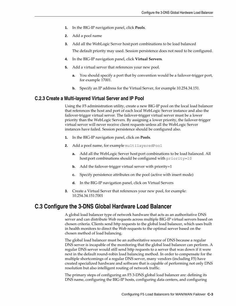
1. In the BIG-IP navigation panel, click Pools.
2. Add a pool name
3. Add all the WebLogic Server host:port combinations to be load balanced
The default priority may used. Session persistence does not need to be configured.
4. In the BIG-IP navigation panel, click Virtual Servers.
5. Add a virtual server that references your new pool.
a. You should specify a port that by convention would be a failover-trigger port,for example 17001.
b. Specify an IP address for the Virtual Server, for example 10.254.34.151.
C.2.3 Create a Multi-layered Virtual Server and IP PoolUsing the F5 administration utility, create a new BIG-IP pool on the local load balancerthat references the host and port of each local WebLogic Server instance and also thefailover-trigger virtual server. The failover-trigger virtual server must be a lowerpriority than the WebLogic Servers. By assigning a lower priority, the failover-triggervirtual server will never receive client requests unless all the WebLogic Serverinstances have failed. Session persistence should be configured also.
1. In the BIG-IP navigation panel, click on Pools.
2. Add a pool name, for example multilayeredPool
a. Add all the WebLogic Server host:port combinations to be load balanced. Allhost:port combinations should be configured with priority=10
b. Add the failover-trigger virtual server with priority=1
c. Specify persistence attributes on the pool (active with insert mode)
d. In the BIG-IP navigation panel, click on Virtual Servers
3. Create a Virtual Server that references your new pool, for example:10.254.34.151:7001
C.3 Configure the 3-DNS Global Hardware Load BalancerA global load balancer type of network hardware that acts as an authoritative DNSserver and can distribute Web requests across multiple BIG-IP virtual servers based onchosen criteria. Clients send http requests to the global load balancer, which uses builtin health monitors to direct the Web requests to the optimal server based on thechosen method of load balancing.
The global load balancer must be an authoritative source of DNS because a regularDNS server is incapable of the monitoring that the global load balancer can perform. Aregular DNS server would still send http requests to a server that was down if it werenext in the default round-robin load balancing method. In order to compensate for themultiple shortcomings of a regular DNS server, many vendors (including F5) havecreated specialized hardware and software that is capable of performing not only DNSresolution but also intelligent routing of network traffic.
The primary steps of configuring an F5 3-DNS global load balancer are: defining itsDNS name, configuring the BIG-IP hosts, configuring data centers, and configuring
Configure the 3-DNS Global Hardware Load Balancer
Configuring F5 Load Balancers for MAN/WAN Failover C-3
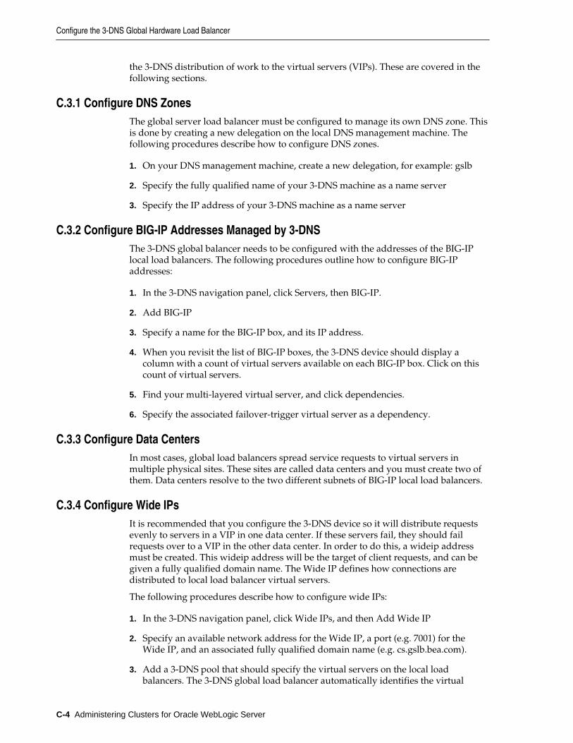
the 3-DNS distribution of work to the virtual servers (VIPs). These are covered in thefollowing sections.
C.3.1 Configure DNS ZonesThe global server load balancer must be configured to manage its own DNS zone. Thisis done by creating a new delegation on the local DNS management machine. Thefollowing procedures describe how to configure DNS zones.
1. On your DNS management machine, create a new delegation, for example: gslb
2. Specify the fully qualified name of your 3-DNS machine as a name server
3. Specify the IP address of your 3-DNS machine as a name server
C.3.2 Configure BIG-IP Addresses Managed by 3-DNSThe 3-DNS global balancer needs to be configured with the addresses of the BIG-IPlocal load balancers. The following procedures outline how to configure BIG-IPaddresses:
1. In the 3-DNS navigation panel, click Servers, then BIG-IP.
2. Add BIG-IP
3. Specify a name for the BIG-IP box, and its IP address.
4. When you revisit the list of BIG-IP boxes, the 3-DNS device should display acolumn with a count of virtual servers available on each BIG-IP box. Click on thiscount of virtual servers.
5. Find your multi-layered virtual server, and click dependencies.
6. Specify the associated failover-trigger virtual server as a dependency.
C.3.3 Configure Data CentersIn most cases, global load balancers spread service requests to virtual servers inmultiple physical sites. These sites are called data centers and you must create two ofthem. Data centers resolve to the two different subnets of BIG-IP local load balancers.
C.3.4 Configure Wide IPsIt is recommended that you configure the 3-DNS device so it will distribute requestsevenly to servers in a VIP in one data center. If these servers fail, they should failrequests over to a VIP in the other data center. In order to do this, a wideip addressmust be created. This wideip address will be the target of client requests, and can begiven a fully qualified domain name. The Wide IP defines how connections aredistributed to local load balancer virtual servers.
The following procedures describe how to configure wide IPs:
1. In the 3-DNS navigation panel, click Wide IPs, and then Add Wide IP
2. Specify an available network address for the Wide IP, a port (e.g. 7001) for theWide IP, and an associated fully qualified domain name (e.g. cs.gslb.bea.com).
3. Add a 3-DNS pool that should specify the virtual servers on the local loadbalancers. The 3-DNS global load balancer automatically identifies the virtual
Configure the 3-DNS Global Hardware Load Balancer
C-4 Administering Clusters for Oracle WebLogic Server
servers available on each local load balancer after the BIG-IP hosts are configured.Specify the multi-layered Virtual Servers.
4. Create two entries in the DNS database on your DNS nameserver that resolve tothe wideip.
C.4 Configuring WebLogic Server ComponentsAfter you have configured your F5 devices, you must configure WebLogic Server touse MAN/WAN failover. For information on configuring WebLogic Server to useMAN/WAN, see Session State Replication Across Clusters in a MAN/WAN.
Configuring WebLogic Server Components
Configuring F5 Load Balancers for MAN/WAN Failover C-5

Configuring WebLogic Server Components
C-6 Administering Clusters for Oracle WebLogic Server
DConfiguring Radware Load Balancers for
MAN/WAN Failover
This appendix describes how to configure Radware hardware load balancers.
WebLogic Server provides failover within MAN and WAN networks. This featureprovides more reliability by allowing failover to occur across a larger geographic area.It also provides failover across multiple WebLogic Server domains.
To provide failover within a MAN/WAN environment, you must use hardware loadbalancers. This document outlines the procedures for configuring Radware hardwareload balancers to work with WebLogic Server.
For information on configuring WebLogic Server to use MAN/WAN, see Session StateReplication Across Clusters in a MAN/WAN. For information on configuringRadware hardware load balancers, see http://www.radware.com.
This appendix includes the following sections:
• Requirements
• Step 1: Configure an Authoritative Delegation Zone
• Step 2: Configure Farm Virtual IPs and Servers
• Step 3: Configure Port Multiplexing
• Step 4: Configure HTTP Redirects
• Step 5: Configure Session ID Persistency
• Step 6: Configure LRP
• Step 7: Configure WebLogic Server Components
D.1 RequirementsBefore performing the procedures described in this appendix, ensure that you haveperformed the following:
• Installed and configured your WebLogic Server environment. This includescreating and configuring clusters and Managed Servers.
• Installed and configured at least two Radware Web Server Director load balancers.This is the minimum hardware requirement for using Radware devices within aMAN/WAN environment. At least one of these must be configured as a globalload balancer
• Ensured that your network and DNS are configured correctly
Configuring Radware Load Balancers for MAN/WAN Failover D-1
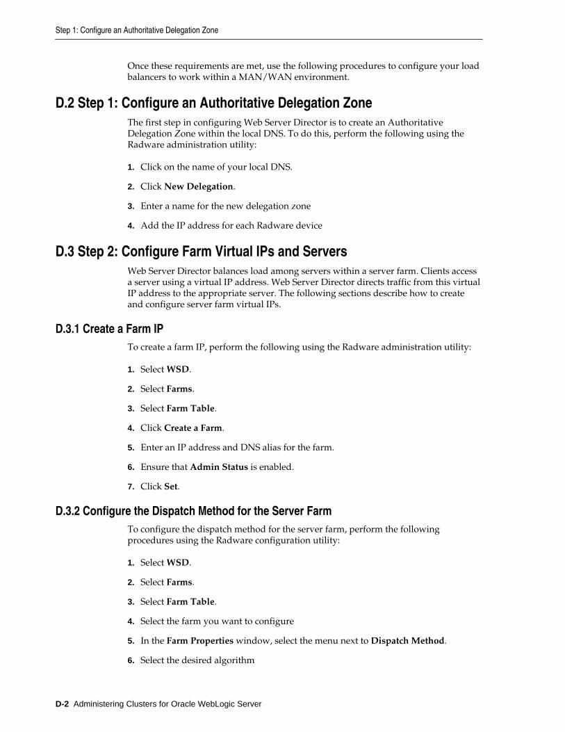
Once these requirements are met, use the following procedures to configure your loadbalancers to work within a MAN/WAN environment.
D.2 Step 1: Configure an Authoritative Delegation ZoneThe first step in configuring Web Server Director is to create an AuthoritativeDelegation Zone within the local DNS. To do this, perform the following using theRadware administration utility:
1. Click on the name of your local DNS.
2. Click New Delegation.
3. Enter a name for the new delegation zone
4. Add the IP address for each Radware device
D.3 Step 2: Configure Farm Virtual IPs and ServersWeb Server Director balances load among servers within a server farm. Clients accessa server using a virtual IP address. Web Server Director directs traffic from this virtualIP address to the appropriate server. The following sections describe how to createand configure server farm virtual IPs.
D.3.1 Create a Farm IPTo create a farm IP, perform the following using the Radware administration utility:
1. Select WSD.
2. Select Farms.
3. Select Farm Table.
4. Click Create a Farm.
5. Enter an IP address and DNS alias for the farm.
6. Ensure that Admin Status is enabled.
7. Click Set.
D.3.2 Configure the Dispatch Method for the Server FarmTo configure the dispatch method for the server farm, perform the followingprocedures using the Radware configuration utility:
1. Select WSD.
2. Select Farms.
3. Select Farm Table.
4. Select the farm you want to configure
5. In the Farm Properties window, select the menu next to Dispatch Method.
6. Select the desired algorithm
Step 1: Configure an Authoritative Delegation Zone
D-2 Administering Clusters for Oracle WebLogic Server
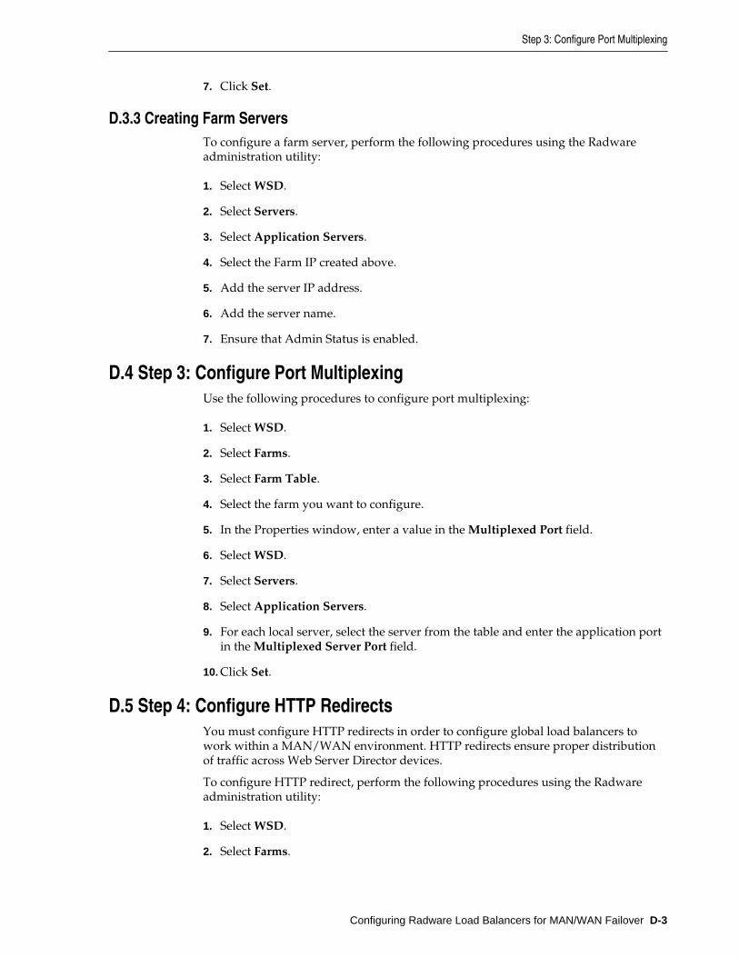
7. Click Set.
D.3.3 Creating Farm ServersTo configure a farm server, perform the following procedures using the Radwareadministration utility:
1. Select WSD.
2. Select Servers.
3. Select Application Servers.
4. Select the Farm IP created above.
5. Add the server IP address.
6. Add the server name.
7. Ensure that Admin Status is enabled.
D.4 Step 3: Configure Port MultiplexingUse the following procedures to configure port multiplexing:
1. Select WSD.
2. Select Farms.
3. Select Farm Table.
4. Select the farm you want to configure.
5. In the Properties window, enter a value in the Multiplexed Port field.
6. Select WSD.
7. Select Servers.
8. Select Application Servers.
9. For each local server, select the server from the table and enter the application portin the Multiplexed Server Port field.
10. Click Set.
D.5 Step 4: Configure HTTP RedirectsYou must configure HTTP redirects in order to configure global load balancers towork within a MAN/WAN environment. HTTP redirects ensure proper distributionof traffic across Web Server Director devices.
To configure HTTP redirect, perform the following procedures using the Radwareadministration utility:
1. Select WSD.
2. Select Farms.
Step 3: Configure Port Multiplexing
Configuring Radware Load Balancers for MAN/WAN Failover D-3
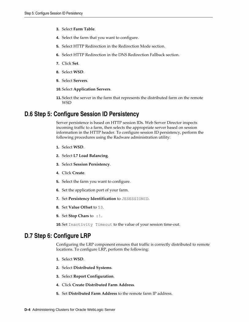
3. Select Farm Table.
4. Select the farm that you want to configure.
5. Select HTTP Redirection in the Redirection Mode section.
6. Select HTTP Redirection in the DNS Redirection Fallback section.
7. Click Set.
8. Select WSD.
9. Select Servers.
10. Select Application Servers.
11. Select the server in the farm that represents the distributed farm on the remoteWSD
D.6 Step 5: Configure Session ID PersistencyServer persistence is based on HTTP session IDs. Web Server Director inspectsincoming traffic to a farm, then selects the appropriate server based on sessioninformation in the HTTP header. To configure session ID persistency, perform thefollowing procedures using the Radware administration utility:
1. Select WSD.
2. Select L7 Load Balancing.
3. Select Session Persistency.
4. Click Create.
5. Select the farm you want to configure.
6. Set the application port of your farm.
7. Set Persistency Identification to JESESSIONID.
8. Set Value Offset to 53.
9. Set Stop Chars to :!.
10. Set Inactivity Timeout to the value of your session time-out.
D.7 Step 6: Configure LRPConfiguring the LRP component ensures that traffic is correctly distributed to remotelocations. To configure LRP, perform the following:
1. Select WSD.
2. Select Distributed Systems.
3. Select Report Configuration.
4. Click Create Distributed Farm Address.
5. Set Distributed Farm Address to the remote farm IP address.
Step 5: Configure Session ID Persistency
D-4 Administering Clusters for Oracle WebLogic Server

6. Set Remote WSD Address to the IP address of the second Radware device.
7. Click Set.
D.8 Step 7: Configure WebLogic Server ComponentsAfter you have configured your Radware devices, you must configure WebLogicServer to use MAN/WAN failover. For information on configuring WebLogic Serverto use MAN/WAN, see Session State Replication Across Clusters in a MAN/WAN.
Step 7: Configure WebLogic Server Components
Configuring Radware Load Balancers for MAN/WAN Failover D-5

Step 7: Configure WebLogic Server Components
D-6 Administering Clusters for Oracle WebLogic Server