option panel instruction manualftmsales.com/danfoss hvac option panel instruction manual...
TRANSCRIPT

Option Panel Instruction ManualUse this manual for installation and start up of drives with option panels.

��������EQUIPMENT HAZARD!OPTION PANELS CONTAIN DANGEROUS VOLTAGES WHEN CONNECTED
TO LINE VOLTAGE. IT IS STRONGLY RECOMMENDED THAT ALL
ELECTRICAL WORK CONFORM TO THE NATIONAL ELECTRICAL CODE
(NEC) AND ALL NATIONAL AND LOCAL REGULATIONS. INSTALLATION,START-UP AND MAINTENANCE SHOULD BE PERFORMED ONLY BY
QUALIFIED PERSONNEL. FAILURE TO FOLLOW THE NEC OR LOCAL
REGULATIONS COULD RESULT IN DEATH OR SERIOUS INJURY.
Motor control equipment and electronic controls areconnected to hazardous line voltages. Extremecare should be taken to protect against shock. Theuser must be protected against supply voltage andthe motor must be protected against overload inaccordance with applicable national and localregulations. Be sure equipment is properlygrounded. Wear safety glasses whenever workingon electric control or rotating equipment.
Safety Guidelines
1. The drive and option panel must bedisconnected from the AC line before anyservice work is done.
2. DO NOT touch electrical parts of the optionpanel or drive when the AC line is connected.After the AC line is disconnected, wait 30minutes before touching any electricalcomponents.
3. The user must be protected against supplyvoltage and the motor must be protectedagainst overload in accordance with applicablenational and local regulations.
4. While programming parameters, the motor maystart without warning. Activate the STOP/OFFkey on the control keypad when changingparameters.
5. The STOP/OFF key on the local control panelkeypad of the drive does not isolate the drivefrom the AC line voltage and is not to be used asa safety switch.
��������UNINTENDED START!WHEN OPTION PANEL IS CONNECTED TO AC INPUT POWER, MOTOR
MAY START AT ANY TIME. THE DRIVE, OPTION PANEL, MOTOR, AND
ANY DRIVEN EQUIPMENT MUST BE IN OPERATIONAL READINESS.FAILURE TO BE IN OPERATIONAL READINESS WHEN PANEL AND
DRIVE ARE CONNECTED TO AC INPUT POWER COULD RESULT IN
DEATH, SERIOUS INJURY, OR EQUIPMENT OR PROPERTY DAMAGE.
Warning Against Unintended Start
When the option panel is connected to the AC line,the motor may be started by means of an externalswitch, a serial bus command, an input referencesignal, or a cleared fault condition. Use appropriatecautions to guard against an unintended start.
��������GROUNDING HAZARD!FOR OPERATOR SAFETY, IT IS IMPORTANT TO GROUND DRIVE, OPTION
PANEL, AND MOTOR PROPERLY. FOLLOW THE GROUNDING GUIDELINES
OF LOCAL AND NATIONAL CODES. FAILURE TO FOLLOW GROUNDING
GUIDLINES COULD RESULT IN DEATH OR SERIOUS INJURY.
Grounding
Correct protective grounding of the equipment mustbe established in accordance with national and localcodes. Ground currents are higher than 3 mA. Usehigh stranded wire whenever possible.

3
Table of Contents
Section 1 Introduction ..........................................................................................5Purpose of the manual ........................................................................................................................ 5Overview ............................................................................................................................................... 5Typical bypass operation ..................................................................................................................... 5Bypass Circuits .................................................................................................................................... 6Bypass Options ................................................................................................................................... 6Bypass Platform Configurations ......................................................................................................... 7Switch Mode Power Supply (SMPS) .................................................................................................... 8Disconnects ......................................................................................................................................... 8Option Panel Configurations ............................................................................................................... 9Option Panel Voltage and Frame Ratings .......................................................................................... 9Section 2 ............................................................................................................................................ 10
Pre-installation.....................................................................................................10Receiving Inspection ......................................................................................................................... 10Pre-installation Check ....................................................................................................................... 11Installation Site Check ....................................................................................................................... 11Harsh Environments ......................................................................................................................... 12
Section 3 Installation ........................................................................................... 13Tools Required .................................................................................................................................. 13Branch Cuitcut Protection .................................................................................................................. 13Drive Fuses ........................................................................................................................................ 13Mechanical Installation ...................................................................................................................... 14Lifting ................................................................................................................................................. 14Electrical Installation ......................................................................................................................... 16Component Identification .................................................................................................................. 17Wire and Cable Access ..................................................................................................................... 18Wire Size ............................................................................................................................................ 19Input Line Connection ....................................................................................................................... 19
Section 4 Start Up ............................................................................................... 22Pre-start Procedure ........................................................................................................................... 22Inspection Prior to Start Up ................................................................................................................ 23Start Up Procedure ............................................................................................................................ 24
Section 5 Electromechanical Bypass (EMB) Operation ..................................26EMB(0) and EMB1 .............................................................................................................................. 28EMB Auto bypass ............................................................................................................................... 29EMB Common Run/Stop ................................................................................................................... 30EMB Run Permissive ......................................................................................................................... 31EMB Overload .................................................................................................................................... 32EMB Safety Interlock .......................................................................................................................... 33EMB Fire Mode ................................................................................................................................... 33EMB Fault Reporting .......................................................................................................................... 34EMB Switches .................................................................................................................................... 34
Section 6 Electronically Controlled Bypass (ECB) Operation........................35Overview ............................................................................................................................................. 35Drive Control Terminals ..................................................................................................................... 36ECB Control Card .............................................................................................................................. 37ECB Drive or Bypass Selection ......................................................................................................... 39ECB Programming ............................................................................................................................ 40ECB Hand/OFF/Auto .......................................................................................................................... 41ECB Mode of Operation ..................................................................................................................... 42Bypass Status Word Bit Examples .................................................................................................... 43ECB Auto Bypass ............................................................................................................................... 44ECB Run Permissive ......................................................................................................................... 45
4
1-1. Basic 3-contactor Bypass Functions ............................................................................................................ 61-2. Bypass Circuit with Options .......................................................................................................................... 71-3. Disconnects ................................................................................................................................................... 81-4. Tier Definitions and Features ......................................................................................................................... 92-1. Sample Panel Label ...................................................................................................................................... 103-1. Drive Input Fuses ......................................................................................................................................... 133-2. Sample Fuse Rating Label ............................................................................................................................ 133-3. Proper Lifting Method ................................................................................................................................... 143-4. Side Cooling Clearance, A2 and A3 Frames ................................................................................................ 153-5. Cooling Airflow ............................................................................................................................................. 153-6. Power Connections ..................................................................................................................................... 163-7. Sample Mechanical Layout Drawing ........................................................................................................... 173-8. Conduit Entry Diagrams ................................................................................................................................ 183-9. Sample Tightening Torque and Wire Rating Table ....................................................................................... 193-10. Control Terminal Location ........................................................................................................................... 213-11. Control Terminals ........................................................................................................................................ 213-12. Serial Communication via EIA-485 ............................................................................................................. 225-1. Customer EMB2 Control Card Terminal Connections ................................................................................... 265-2. EMB2 Control Card ....................................................................................................................................... 275-3. EMB(0) Control Connector ........................................................................................................................... 285-4. EMB1 Control Card ....................................................................................................................................... 285-5. Sample Overload Device .............................................................................................................................. 326-1. Local Control Panel (LCP) ............................................................................................................................ 356-2. Drive Control Terminals ................................................................................................................................ 366-3. ECB Control Card Terminal Functions .......................................................................................................... 37
1-1. Contactor Operation ........................................................................................................................................ 61-2. Bypass Configurations ................................................................................................................................... 71-3. Panel Voltage and Frame Ratings ................................................................................................................... 93-1. Tools Required ............................................................................................................................................... 133-2. Approximate Shipping Weights ..................................................................................................................... 143-3. Temperature Ratings ..................................................................................................................................... 153-4. Reference Designator Definitions ................................................................................................................. 174-1. Inspection Prior to Start Up............................................................................................................................ 235-1. EMB2 Control Card Terminal Functions ......................................................................................................... 265-2. EMB2 Parameter Settings .............................................................................................................................. 275-3. Typical HVAC Control Connections ............................................................................................................... 275-4. EMB(0) Terminal Functions ............................................................................................................................ 285-5. EMB1 Terminal Functions .............................................................................................................................. 285-6. EMB1 Parameter Settings .............................................................................................................................. 286-1. Drive Control Terminal Functions .................................................................................................................. 366-2. ECB Card Terminals ....................................................................................................................................... 386-3. LCP Control Keys Programming .................................................................................................................... 416-4. Bypass Parameter Functions ....................................................................................................................... 426-5. Parameter 31-10 Bypass Status Word Bit Definitions .................................................................................. 438-1. Option Panel Alarms and Warnings .............................................................................................................. 518-2. Option Panel Status Display .......................................................................................................................... 518-3. Fault Table ..................................................................................................................................................... 52
List of Figures
List of Tables
ECB Overload .................................................................................................................................... 46ECB Safety Interlock .......................................................................................................................... 47ECB Common Run/Stop ................................................................................................................... 47ECB Advanced Fire Mode .................................................................................................................. 48ECB Fault Reporting .......................................................................................................................... 48
Section 7 Non-bypass Component Functions .................................................. 49Power Fusing ..................................................................................................................................... 49Reactors ............................................................................................................................................ 49Disconnects ....................................................................................................................................... 49Motor Options ..................................................................................................................................... 50Contactor Motor Select ...................................................................................................................... 51
Section 8 Start Up Troublehooting ....................................................................52Option Panel Alarm and Warnings .................................................................................................... 52

5
Section 1Introduction
Purpose of the manualThis manual is intended to provide detailedinformation for the installation and operation of theoption panel used in conjunction with a Danfossvariable frequency drive (VFD or drive). To enableefficient handling of the equipment, requirementsare provided for installation of mechanical,electrical, and control wiring, proper grounding, andenvironmental considerations. Pre-start and start upprocedures are detailed. Also included is a detailedoverview of the option panel bypass function. Inaddition, identification of other optional componentsand their operation and start up troubleshootinginstructions are included. For the electronicallycontrolled bypass, additional programming andoperation information is provided.
OverviewA variable frequency drive regulates the speed andoperation of an electric motor(s). The drive isprogrammable and offers many features andsavings compared to operating a motor fromunregulated line voltage. The option panel is aprotective enclosure in which the drive and variousoptional components are assembled and mounted.One of the most common functions of the optionpanel is to allow switching between VFD control andrunning in bypass. In bypass, the motor is operateddirectly from line input power.
Two types of bypass options are available: theelectromechanical bypass (EMB) and electronicallycontrolled bypass (ECB). The EMB is operated byselector switches on the front of the panel. TheEMB controls a motor(s) by switching betweendrive control, operation in bypass, or off. In addition,a test setting is available which disengages themotor from the drive but keeps the drive operationalwhile the motor runs in bypass. The switching
function activates contactors that open or close toprovide power to the motor through the drive orbypass circuitry, as required.
The ECB also uses contactors to provide power tothe motor through the drive or bypass circuitry.However, the ECB contains a local processor whichinteracts with the drive’s control logic forprogrammable options, remote inputs, and statusreporting. The VFD’s logic circuitry is backed up byan independent panel-mounted power supply sothat, even if the drive loses power, control andcommunication functions are maintained.Programming and display are provided by theVFD’s keypad. An important feature of the ECB isthe ability to accept commands from a buildingautomation system (BAS) and to report operationalstatus in return.
See more detailed descriptions of the EMB inSections 5 and ECB in Section 6 of this manual.
Typical bypass operationWith contactors M1 and M2 closed and contactorM3 open (see Figure 1-1), the motor is running indrive control. Opening contactor M2 removes powerto the motor but allows the drive to remain underpower. This is the test mode and only available inthe three-contactor configuration shown. Withcontactors M1 and M2 open and contactor M3closed, the motor is running in bypass from the lineinput. For a two-contactor configuration, M1 isabsent. In this case, contactors M2 and M3 controlthe options for running in drive or bypass mode. Thedrive disconnect and fuses shown in the figure iscontrolled by an ON/OFF disconnect on the bypasspanel.

6
Bypass Circuits
Two-contactor bypass. This bypass consists ofmotor starter circuitry used in bypass, a bypasscontactor (M3) interlocked with a drive outputcontactor (M2) mounted in the bypass enclosure.For the electromechanical bypass (EMB), anenclosure-mounted Drive/OFF/Bypass selector isused to electrically select whether the motor iscontrolled by the drive, connected to the full-speedbypass, or disconnected from both. The contactorand motor starter are controlled by this switch. Alight indicates when in bypass. For the electronicallycontrolled bypass (ECB), control selection is madethrough the drive keypad by pressing the DRIVEBYPASS key and selecting from the availableoptions shown. Display data indicates when inbypass. A drive disconnect is also available with thetwo-contactor bypass and is required for the optionpanel components without bypass.
Three-contactor bypass. This bypass consists ofmotor starter circuitry used in bypass, a bypasscontactor (M3) interlocked with a drive outputcontactor (M2), a drive input contactor (M1), and anoverload relay mounted in the option panel. For the
EMB, an enclosure mounted Drive/OFF/Bypass/Test switch is used to electrically select whether themotor is driven by the drive, connected to the full-speed bypass, or disconnected from both. The testposition applies power to the motor through thebypass (M3 closed) while removing power to themotor (M2 open) but keeps the drive powered (M1closed). A light indicates when in bypass. For theECB, control selection is made through the drivekeypad by pressing the DRIVE BYPASS key andselecting from the available options shown. Displaydata indicates when in bypass. The circuitry may besupplied with either an input disconnect switch oran input circuit breaker.
Bypass Options
Common run/stop with bypass. Allows a commonremote signal through the VFD input terminals toinitiate operation in either drive control or bypass. Arelay closure starts the motor(s) in drive or bypass,depending upon the position of the bypass selectorswitch.
Automatic bypass. Automatically transfers themotor(s) from drive to bypass without operatorintervention when a fault condition trips the drive,after a programmable time-out period. The VFD’sinternal fault circuitry controls this action. The timedelay permits all automatically resettable faults toclear prior to transfer to bypass. Run permissive orsafety circuit signals override the auto bypassfunction and may prevent or delay running inbypass.
Figure 1-1. Basic 3-contactor Bypass Functions
Contactor Drive Mode OFF Bypass Mode Test Mode M1 Closed Open Open Closed M2 Closed Open Open Open M3 Open Open Closed Closed
Table 1-1. Contactor Operation

7
Run permissive in bypass. With run permissiveactive, the drive sends a run request and waits for aremote response to before notifying the motor tostart. The response indicates the system is safe tooperate.
Basic fire mode in bypass. This option switchesthe panel to bypass whenever a remote fire modecommand is given to the VFD through the inputterminals. In either drive or bypass, fire mode isintended to ignore common safety and overloadinputs in emergency situations. The motor willcontinue to run in bypass until fire mode is removedor the drive or option panel fail. External safetysignals and motor overload are ignored when in firemode.
Advanced fire mode in bypass. The advancedfire mode allows for a variety of programmableresponses to an external fire mode commandsignal. Bypass options are programmed throughthe drive’s fire mode parameters. See fire modesection of the drive manual and supportmaterials for available options.
Overload protection. This thermally activated deviceprovides mechanical overload protection for themotor(s) while in bypass operation. It measures motorcurrent and is set to the full load amps (FLA) of themotor. A 1.2 x FLA service factor is built-in andmaintained, meaning that should the motor currentincrease above that value, the overload will calculate thelevel of increase to activate timing for the trip function.The higher the current draw, the quicker the tripresponse. It provides Class 20 motor protection.
Bypass Platform Configurations
The EMB is available in three platforms: EMB(0),EMB1, and EMB2. The features available as optionswith each platform are listed in Table 1-2. The ECB,also listed below, has all option features available.See Section 5 for additional details on the EMB andSection 6 for the ECB.
Figure 1-2. Bypass Curcuit with Options
Table 1-2. Bypass Configurations
EMB(0) EMB1 EMB2 ECBX X X X
X X XX XX XX X
XX
Basic Fire ModeAdvanced Fire ModeSerial Communication
Control Feature
Common Start / StopAutomatic BypassRun Permissive in Bypass
Safety Interlock

8
Disconnects
Main disconnect. The main discon-nect removes line input power to thedrive and bypass. A main disconnect isavailable in four options.
• Fused disconnect. Two-position(ON/OFF) rotary switch, padlockcompatible, with three fuses, oneon each phase, built into theswitch. For safety, the switch mustbe in the OFF position before theoption panel door can be opened.
• Disconnect with fuses. Two-position (ON/OFF) rotary switch,padlock compatible, with a fuseblock mounted separately fromthe disconnect. Three fuses, oneon each phase, are located on thefuse block. For safety, the switchmust be in the OFF positionbefore the option panel door canbe opened.
• Disconnect without fuses. Foruser-supplied fuses option.
Figure 1-3. Disconnects
DRIVEDRIVEDISCONNECTDISCONNECT
MAINMAINDISCONNECTDISCONNECT
BYPASS BYPASSSELECTOR SELECTORSWITCHSWITCH
• Main circuit breaker. A thermal/magnetic current interrupt deviceusing an ON/TRIP/OFF/RESETswitch. When in the ON position, atrip fault removes power from thedrive/bypass circuit and the switchmoves to the TRIP setting. It mustbe moved to the RESET positionmomentarily after the fault hasbeen cleared to reset the circuitbreaker.
Drive disconnect (optional). Two-position (ON/OFF) rotary switchdisconnects main AC line input powerto the drive only.
Bypass selector switch. The bypassselector switch is used for either the 2-contactor or 3-contactor bypass forEMB units.
Switch Mode Power Supply (SMPS)
The VFD’s logic circuitry is backed up by anindependent panel-mounted switch mode powersupply so that, even if the drive loses power, thecontrol and communication functions aremaintained. The SMPS converts three-phase ACinput power to 24 VDC control power. Since theSMPS draws power from all three phases, it offersimmunity protection from most phase-loss andbrown-out conditions. The SMPS is internallyprotected from short circuit on its output and threeboard-mounted fuses provide additional protection.The SMPS is not designed for external use and maytake up to 5 seconds to initialize at power-up.

9
Option Panel ConfigurationsThe VLT FC Drive Series has three tiers of optionpanel enclosure types. These designations areuniversal for both the EMB and ECB panels as well
Tier 1 Tier 2 Tier 3
Figure 1-4. Tier Definitions and Features
Drive plus either or both of the following:
1. Fuses
2. Disconnect
Drive with bypass or up to two of the following:
1. Contactor motor selection
2. dV/dt filter or input AC line reactor (NEMA 1 only)
3. Dual motor control
Drive with bypass plus up to two of the following:
1. Contactor motor selection
2. dV/dt filter or input AC line reactor (NEMA 1 only)
3. Dual motor control
Option Panel Voltage and Frame RatingsTable 1-3 defines the voltage and hp ratings of theframes sizes for the option panel. See themechanical drawing shipped with the unit fordimensions.
Volts VAC hp208-230 1.5-5460-480 1.5-10575-600 1.5-10
Frames A2 - A5
Volts VAC hp208-230 7.5-15460-480 15-25575-600 15-25
Frame B1
Volts VAC hp208-230 20460-480 30-40575-600 30-40
Frame B2
Volts VAC hp208-230 25-30460-480 50-75575-600 50-75
Frame C1
Volts VAC hp208-230 40-60460-480 100-125575-600 100-125
Frame C2
Table 1-3. Panel Voltage and Frame Ratings
Table 1-3. Panel Voltage and Frame Ratings(Cont.)
as drive options without bypass. See Figure 1-4 fordescriptions and available options.
Volts VAC hp460-480 150-200575-600 150-200
Frame D1
Volts VAC hp460-480 250-350575-600 250-400
Frame D2

10
Danfoss Inc.Milwaukee, WI 53224, U.S.A.Tel.: +1 (800) 432-6367 Fax.: +1 (815) 639-8002
Material No.: 174H2222Drawings: 176U8989Input Power: 480 VAC, 65.7 A, 3 Ø, 60 HzMotor: 460 VAC, 65 AShort Circuit Rating: 5 kA rms sym. at rated input V max.Envir. Rating: UL Type 1Max. Ambient: 45 °C/ 113 °F
Serial No.: 018702Y097
Humidity: 95 % Non-Cond.
S301050T4E013CMM13XSXXZ1XGCXXXXXXXXXXXX0See information packet for installation instructions.
Section 2Pre-installation
Receiving InspectionInspect the packaging and equipment closelywhen received. Any indication of careless handlingby the carrier should be noted on the deliveryreceipt, especially if the equipment will not beimmediately uncrated. Obtain the deliveryperson’s signed agreement to any noteddamages for any future insurance claims.
If goods are received short or in damaged condition, insist on a notationof the loss or damage across the face of the freight bill. Otherwise noclaim can be enforced against the transportation company.
If concealed loss or damage is discovered, notify your carrier at onceand request an inspection. This is absolutely necessary. Unless you dothis the carrier will not entertain any claim for loss or damage. The agentwill make an inspection and can grant a concealed damage notation. Ifyou give the transportation company a clear receipt for equipment thathas been damaged or lost in transit, you do so at your own risk andexpense.
DANFOSS IS WILLING TO ASSIST YOU TO COLLECT CLAIMS FORLOSS OR DAMAGE, BUT WILLINGNESS ON OUR PART DOES NOTMAKE US RESPONSIBLE FOR COLLECTION OF CLAIMS ORREPLACEMENT OF MATERIAL. THE ACTUAL FILING AND PROCESS-ING OF THE CLAIM IS YOUR RESPONSIBILITY.
IMPORTANT
LOST OR DAMAGED GOODS
INSPECT THIS SHIPMENTIMMEDIATELY UPON ARRIVAL
Ensure that the model number and power matchthe order and intended use for the drive.
Panel output ratingPanel input rating Serial number
Figure 2-1. Sample Panel Label

11
1. Compare option panel model number towhat was ordered.
2. Ensure each of following are rated forsame voltage:
• Drive• Option panel• Power line• Motor
3. Ensure that panel output rating is equal toor greater than motor total full load currentfor full motor performance.
• For multiple motor applications, add thefull load current ratings of all motors.
• Motor power size and option panel mustmatch for proper overload protection.
• If panel rating is less than motor, full motoroutput cannot be achieved.
4. Check motor wiring:
• Any disconnect between drive and motorshould be interlocked to drive safetyinterlock circuit to avoid unwanted drivetrips.
• Do not connect power factor correctioncapacitors between drive and motor.
• Two speed motors must be wiredpermanently for full speed.
• Y-start, -run motors must be wiredpermanently for run.
Pre-installation Check Installation Site Check
• Because the option panel relies on theambient air for cooling, it is important toobserve the limitations on ambient airtemperature. Derating concerns start above40°C (104°F) and 3300 (1000m) feetelevation above sea level.
• It is important with multiple panels to checkwall strength. Make sure that the propermounting screws or bolts are used.
• Ensure that the wall or floor area forinstallation will support the weight of the unit.
• If construction work continues after theequipment is mounted, it is important to keepthe interior free from concrete dust andsimilar dirt. If the unit does not have powerapplied to it, supply a protective covering. It isimportant to ensure that the componentsstay as clean as possible. It may benecessary to clean the interior onceconstruction is completed.
• Keep drawings and manuals accessible fordetailed installation and operationinstructions. It is important that the manualsbe available for equipment operator.

12
Harsh Environments
The mechanical and electrical components withinthe option panel can be adversely affected by theenvironment. The effects of contaminants in the air,either solid, liquid, or gas, are difficult to quantify andcontrol.
Airborne Liquids
Liquids in the air can condense in components.Water carried in the air is easily measured asrelative humidity, but other vapors are often moredifficult to measure or control. Steam, oil and saltwater vapor may cause corrosion of components.In such environments, use NEMA 12 enclosures tolimit the exchange of outside air into the optionenclosure. Extremely harsh environments mayrequire a higher level of protection.
Airborne Solids
Particles in the air may cause mechanical,electrical or thermal failure in components. A NEMA1 enclosure provides a reasonable degree ofprotection against falling particles, but it will notprevent the fan from pulling dirty air into theenclosure. A typical indicator of excessive levels ofairborne particles is dust around the fan. In dustyenvironments, use NEMA 12 enclosures.
Corrosive Chemicals
In environments with high temperatures andhumidity, corrosive gases such as sulfur, nitrogenand chlorine compounds cause corrosion to occurin components. Indications of corrosion areblackened copper or rust on steel or oxidizedaluminum. In such environments, it isrecommended that the equipment be mounted in acabinet with fresh air ventilation and that corrosivecompounds be kept away. A non-ventilated cabinetfitted with an air conditioner as a heat exchangermay be used. Conformal coated circuit boards maybe specified to reduce the corrosive effects of aharsh environment.
13
Section 3Installation
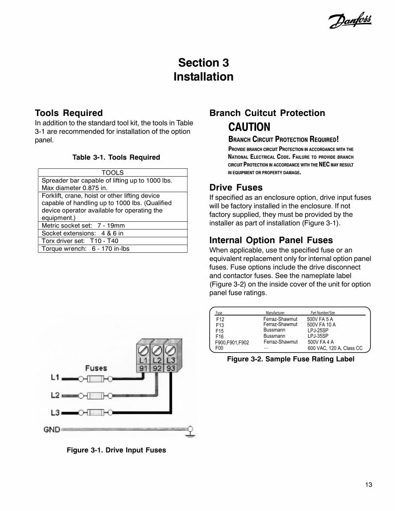
Branch Cuitcut Protection
CAUTIONBRANCH CIRCUIT PROTECTION REQUIRED!PROVIDE BRANCH CIRCUIT PROTECTION IN ACCORDANCE WITH THE
NATIONAL ELECTRICAL CODE. FAILURE TO PROVIDE BRANCH
CIRCUIT PROTECTION IN ACCORDANCE WITH THE NEC MAY RESULT
IN EQUIPMENT OR PROPERTY DAMAGE.
Figure 3-1. Drive Input Fuses
Drive FusesIf specified as an enclosure option, drive input fuseswill be factory installed in the enclosure. If notfactory supplied, they must be provided by theinstaller as part of installation (Figure 3-1).
Internal Option Panel FusesWhen applicable, use the specified fuse or anequivalent replacement only for internal option panelfuses. Fuse options include the drive disconnectand contactor fuses. See the nameplate label(Figure 3-2) on the inside cover of the unit for optionpanel fuse ratings.
Fuse Manufacturer Part Number/Size
F12F13F15F16
F00F900,F901,F902
Ferraz-ShawmutFerraz-Shawmut
Ferraz-Shawmut
BussmannBussmann
…
500V FA 5 A500V FA 10 ALPJ-25SPLPJ-35SP500V FA 4 A600 VAC, 120 A, Class CC
Figure 3-2. Sample Fuse Rating Label
Tools RequiredIn addition to the standard tool kit, the tools in Table3-1 are recommended for installation of the optionpanel.
Table 3-1. Tools Required
TOOLS Spreader bar capable of lifting up to 1000 lbs. Max diameter 0.875 in. Forklift, crane, hoist or other lifting device capable of handling up to 1000 lbs. (Qualified device operator available for operating the equipment.) Metric socket set: 7 - 19mm Socket extensions: 4 & 6 in Torx driver set: T10 - T40 Torque wrench: 6 - 170 in-lbs

14
Mechanical Installation
Lifting
Check the weight of unit to determine the safety ofthe lifting method. Ensure that the lifting device issuitable for the task. If necessary, plan for a hoist,crane or forklift with appropriate rating to move theunits.
Hoist or Overhead Lift
• Use solid steel spreader bar for lifting. Slidespreader bar through two (2) lifting rings ondrive. Lifting rings are 0.75 inches (19 mm)in diameter (Figure 3-3).
• Connect spreader bar to a hoist or otherlifting device.
• Lift unit slightly using lifting rings with weightdistributed evenly.
• Remove skid and other supports from underdrive.
• For floor mounting applications, a floormounting kit is available from Danfossspecifically designed to anchor drive to floor.
Forklift
• Only a competent lift operator with additionalsupport personnel should attempt movingunit.
• Carefully position forklift and ensure stabilityprior to lift.
Shipping Weights
Figure 3-3. Proper Lifting Method
28 in. min
Frame Tier 1 Tier 2 Tier 3A2-A3 30 35 55
A5 35 55 80B1 65 85 110B2 70 105 180C1 100 145 215C2 130 190 285D1 220 420 585D2 320 575 950
NOTEWEIGHTS LISTED BELOW ARE APPROXIMATE FOR BASE UNITS.OPTIONS CAN ADD OR REDUCE WEIGHT OF UNIT. WEIGHTS LISTED
ARE IN LBS.
Table 3-2. Approximate Shipping Weights

15
Cooling
• Mount the drive and panel vertically.
• Option panels rely on the ambient air forcooling, it is important to observe thelimitations on ambient air temperature. SeeTable 3-3 for temperature rating data.Derating concerns start above 3300 feetelevation above sea level.
• Most option panels with drives may bemounted side-by-side without additional sideclearance. A-2 and A-3 units require 1.5 in.clearance between units (see Figure 3-4).
• Top and bottom clearance is required forcooling (Figure 3-5). Generally, 4 to 10inches (100 to 250 mm) minimum clearanceis required, depending upon the hp (kW) ofthe unit. See the mechanical drawingshipped with the unit for specificrequirements.
Figure 3-5. Cooling Airflow
Mechanical Installation
Frame Size NEMA 1 NEMA 12
A2-A3 113o F NA
A5 NA 104o F
B1-C1 113o F 104o F
C2, D1-D2 104o F 104o F
Temperature Ratings
Table 3-3. Temperature Ratings
Figure 3-4. Side Cooling Clearance, A-2 and A-3Frames
• No additional back plate is required for driveswith the option panel.
• Units may be mounted flush to the wall orfree standing. A free-standing mounting kit isavailable from Danfoss.
• See Table 3-3 for temperature ratings.
4.0 in min.
CEILING
FLOOR
AIRFLOW
4.0 in min.1.5 in min.1.5 in min.

16
��������EQUIPMENT HAZARD!ROTATING SHAFTS AND ELECTRICAL EQUIPMENT CAN BE HAZARDOUS.IT IS STRONGLY RECOMMENDED THAT ALL ELECTRICAL WORK
CONFORM TO ALL NATIONAL AND LOCAL REGULATIONS.INSTALLATION, START-UP AND MAINTENANCE SHOULD BE PERFORMED
ONLY BY QUALIFIED PERSONNEL. FAILURE TO FOLLOW LOCAL
REGULATIONS COULD RESULT IN DEATH OR SERIOUS INJURY.
• Motor control equipment and electroniccontrols are connected to hazardous linevoltages. Extreme care should be taken toprotect against electrical hazard.
• Correct protective grounding of theequipment must be established. Groundcurrents are higher than 3 mA.
• A dedicated ground wire is required.
• Wear safety glasses whenever working onelectric control or rotating equipment.
��������INDUCED VOLTAGE!RUN OUTPUT MOTOR CABLES FROM MULTIPLE DRIVES SEPARATELY.INDUCED VOLTAGE FROM OUTPUT MOTOR CABLES RUN TOGETHER
CAN CHARGE EQUIPMENT CAPACITORS EVEN WITH THE EQUIPMENT
TURNED OFF AND LOCKED OUT. FAILURE TO RUN OUTPUT MOTOR
CABLES SEPARATELY COULD RESULT IN DEATH OR SERIOUS INJURY.
NOTERUN INPUT POWER, MOTOR WIRING AND CONTROL WIRING IN THREE
SEPARATE METALLIC CONDUITS OR RACEWAYS FOR HIGH FREQUENCY
NOISE ISOLATION. FAILURE TO ISOLATE POWER, MOTOR AND
CONTROL WIRING COULD RESULT IN LESS THAN OPTIMUM DRIVE AND
ASSOCIATED EQUIPMENT PERFORMANCE.
• Because the wiring from the optionenclosure to the motor carries highfrequency electrical pulses, it is importantthat no other wires are run in this conduit. Ifthe incoming power wiring is run in the sameconduit as the motor wiring, these pulsescan couple electrical noise back onto thebuilding power grid.
At least three separate conduits must be connectedto the panel option (Figure 3-6).
• Power into the option enclosure (and groundback to the distribution panel)
• Power from the option enclosure to themotor (and earth ground)
• Control wiring
Control wiring should always be isolated from thehigh voltage power wiring.
Avoid getting metal chips into electronics.
Follow the connection procedures as illustrated inthe drawing drovided with the unit.
Figure 3-6. Power Connections
NOTEMAKE ALL POWER CONNECTIONS WITH MINIMUM 75O C RATED
COPPER WIRING FOR INSTALLATIONS IN NORTH AMERICA.
Electrical Installation

17
Component IdentificationMechanical layout drawings are provided inside thecover of each unit with an option panel. Theseillustrations are intended to provide the installer orequipment user with component identification and
Figure 3-7. Sample Mechanical Layout Diagram
Table 3-4. Reference Designator Definitions
Electrical Installation
location for that specific unit. Figure 3-7 representsa typical layout drawing. Table 3-4 providesdefinitions for drawing reference designators. (Notall reference designators are shown.)
ID Definition Function
M5 Motor 2 contactor Used to select motor 2 operationMT1 Motor 1 connection terminal Provides termination point for motor leads in option
panelOL1 Overload for motor 1 Provide overload protection to motor when running
in bypassOL2 Overload for motor 2 Provide overload protection to motor when running
in bypassPL2 Bypass indicator light Provides indication when motor is in bypass mode
S1 Bypass selector switch Operator interface for bypass mode selection on electromechanical bypass
S103 Auto bypass selection switch 4 position switch used to setup auto bypass on EMB2 control option
S2 CMS selector switch Operator interface for contactor motor selectionT1 120 Vac control transformer Provide internal 120 Vac supplyT3 120 Vac control transformer Provide customer 120 Vac supplyTB1 Terminal block 1 Customer bypass control connections for ECB-CMS
and EMB0 control optionVFD Variable frequency drive Provide variable frequency and voltage to AC motor
X55 Customer terminal block Customer control connection terminal block on EMB1 and EMB2 control option
X56 Customer terminal block Customer control connection terminal block on EMB1 and EMB2 control option
X58 Customer terminal block Customer control connection terminal block on EMB2 control option
ID Definition Function
24V Option panel 24 Vdc SMPS Supply 24 Vdc control power to option panel for internal use only
CB1 Main circuit breaker Provide isolation between option panel and current protection for incoming mains
DS1 Main or line disconnect Provide isolation between option panel and mains
DS2 Drive disconnect Provide isolation between VFD and line voltageDF15 Main fused disconnect Provide isolation between option panel and mains
DV1 VFD output motor filter Output filter to provide filtering for PWM drive outputwave form
F12 T1 secondary fuse Current protection for internal 120 Vac control circuit
F13 T1 primary fuse Current protection for line side of 120 Vac internal control transformer
F15 Line or main fuse Provide current protection to option panel
F16 Drive fuse Provide current protection to drive
GD ground terminal Customer connection for power grounds to mains and motor
LR1 VFD input line reactor Input reactor to provide additional input impeadanceto drive
M1 VFD input contactor Provide isolation between VFD and line voltage
M2 VFD output contactor Provide isolation between VFD and motor
M3 Bypass contactor Provide line voltage to motor
M4 Motor 1 contactor Used to select motor 1 operation
GD GD
M1
M2 M3
VFD 24V
F16
DS2
OPTIONAL
F15
DS1 CB1
MT1OL1
OPTIONAL
OUTPUT MOTOR CONNECTIONT1,T2,T3
OPTIONALINPUT POWERCONNECTION L1,L2,L3
GD
PL2S1TB1

18
Wire and Cable Access
• Determine the wiring path through the optionpanel enclosure. See the mechanical layoutdrawing located on the inside cover of theunit for locations to connect power andmotor wiring.
• Removable access covers are provided forcable connections (see Figure 3-8). Removeaccess covers prior to drilling holes toprevent metal shavings from damaginginternal electronic components.
• For some units, access holes are providedfor input power, motor leads, and controlwiring.
• Run input power, motor wiring, and controlwiring in three separate conduits forisolation.
NOTERUN INPUT POWER, MOTOR WIRING AND CONTROL WIRING IN THREE
SEPARATE METALLIC CONDUITS OR RACEWAYS FOR HIGH FREQUENCY
NOISE ISOLATION. FAILURE TO ISOLATE POWER, MOTOR AND
CONTROL WIRING COULD RESULT IN LESS THAN OPTIMUM DRIVE AND
ASSOCIATED EQUIPMENT PERFORMANCE.
• The drive always resides in the left-handpanel when multiple panels are present.
• Power connections are typically on the right-side panel, or far right for tier 3 panelconfigurations.
• NEMA 12 enclosures available for additionalenvironmental protection.
• Control wiring should be isolated from powercomponents inside the unit as much aspossible.
• See the mechanical layout drawing on theinside of the unit’s panel and the connectiondiagram supplied with the unit for connectiondetails.
Electrical Installation
Tier 1 (bottom view)
Control wiring
Input power
Motor power
Tier 2 (bottom view) NEMA 1
Tier 3 (bottom view) NEMA 1
Tier 2 (bottom view) NEMA 12
Bypass
Bypass
Bypass
Drive
Drive
Drive Additional options
Figure 3-8. Conduit Entry Diagrams

19
• Size wiring to the input current of the drive.Recommended wire sizes are provided onthe connection drawing inside the cover ofthe unit.
• Local codes must be complied with for cablesizes.
Wire Type Rating
• Use wiring corresponding to the wiring ratingspecifications provided.
• The wire rating specifications are located onthe tightening torque and wire rating labelinside the cover of the option panel (seeFigure 3-8).
Terminal Tightening Torques
• Tighten all connections to the torquespecifications provided.
• The torque tightening specifications arelocated on the tightening torque and wirerating label inside the cover of the optionpanel (see Figure 3-9.)
NOTEMAKE ALL POWER CONNECTIONS WITH MINIMUM 75O C RATED
COPPER WIRING FOR INSTALLATIONS IN NORTH AMERICA.
Electrical Installation
Wire Size Input Line Connection
NOTERUN INPUT POWER, MOTOR WIRING AND CONTROL WIRING IN THREE
SEPARATE METALLIC CONDUITS OR RACEWAYS FOR HIGH FREQUENCY
NOISE ISOLATION. FAILURE TO ISOLATE POWER, MOTOR AND
CONTROL WIRING COULD RESULT IN LESS THAN OPTIMUM DRIVE AND
ASSOCIATED EQUIPMENT PERFORMANCE.
• Connect 3-phase AC input power wire toterminals L1, L2, and L3. See the connectiondrawing inside the cover of the unit.
• Depending on the configuration of theequipment, input power may be connected toa circuit breaker or input disconnect.
• Torque terminals in accordance with theinformation provided on the connectiondiagram inside the cover of the unit.
• Use with Isolated Input Source. Manyutility power systems are referenced to earthground. Although not as common, the inputpower may be an isolated source. All drivesmay be used with an isolated input sourceas well as with ground reference powerlines.
Figure 3-9. Sample Tightening Torque and Wire Rating Label
Field Conn. Tightening Torque lb-in (N-m) Temperature & Type Rating
L1, L2, L3 / GND1T1, 1T2, 1T3 / GND2T1, 2T2, 2T3 / GNDTB1
25 (2.8) / 25 (2.8)25 (2.8) / 25 (2.8)25 (2.8) / 25 (2.8)7 (0.8)
Use 75 °C Copper Cond.Use 75 °C Copper Cond.Use 75 °C Copper Cond.Use 60 °C Copper Cond.

20
Grounding (Earthing)
��������GROUNDING HAZARD!FOR OPERATOR SAFETY, IT IS IMPORTANT TO GROUND OPTION
PANEL PROPERLY. FAILURE TO GROUND OPTION PANEL PROPERLY
COULD RESULT IN DEATH OR SERIOUS INJURY.
NOTE
IT IS THE RESPONSIBILITY OF THE USER OR CERTIFIED ELECTRICAL
INSTALLER TO ENSURE CORRECT GROUNDING (EARTHING) OF THE
EQUIPMENT IN ACCORDANCE WITH NATIONAL AND LOCAL ELECTRICAL
CODES AND STANDARDS.
• Follow all local and national codes for properelectrical equipment grounding (earthing).
• Correct protective grounding of theequipment must be established. Groundcurrents are higher than 3 mA.
• A dedicated ground wire is required.
• Connect the ground wire directly to a reliableearth ground. Grounding studs are providedon the back plate of the option panel forgrounding.
• Do not use conduit connected to the optionpanel as a replacement for a ground wire.
• Do not ground one panel to another in a“daisy chain” fashion. Each panel must havea dedicated ground connection.
• A high strand count ground wire is preferredfor dissipating high frequency electricalnoise.
• Keep the ground wire connections as shortas possible.
Motor Wiring
��������INDUCED VOLTAGE!RUN OUTPUT MOTOR CABLES FROM MULTIPLE DRIVES SEPARATELY.INDUCED VOLTAGE FROM OUTPUT MOTOR CABLES RUN TOGETHER
CAN CHARGE EQUIPMENT CAPACITORS EVEN WITH THE EQUIPMENT
TURNED OFF AND LOCKED OUT. FAILURE TO RUN OUTPUT MOTOR
CABLES SEPARATELY COULD RESULT IN DEATH OR SERIOUS INJURY.
NOTERUN INPUT POWER, MOTOR WIRING AND CONTROL WIRING IN THREE
SEPARATE METALLIC CONDUITS OR RACEWAYS FOR HIGH FREQUENCY
NOISE ISOLATION. FAILURE TO ISOLATE POWER, MOTOR AND
CONTROL WIRING COULD RESULT IN LESS THAN OPTIMUM DRIVE AND
ASSOCIATED EQUIPMENT PERFORMANCE.
• Connect the 3-phase motor wiring to bypassterminals T1 (U), T2 (V), and T3 (W). Seethe connection drawing inside the cover ofthe unit.
• Depending on the configuration of theequipment, motor wiring may be connectedto an electrical or mechanical overload, acontactor, or terminal block.
• Torque terminals in accordance with theinformation provided on the connectiondiagram inside the cover of the unit.
• Motor wiring should never exceed thefollowing maximum distances:
1000 ft (300m) for unshielded500 ft (150m) for shielded
• Motor wiring should always be as short aspractical.
Electrical Installation

21
Control Wiring
• It is recommended that control wiring is ratedfor 600 V for 480 V and 600 V drives and 300V for 200-240 V drives.
• Isolate control wiring from high powercomponents in the drive.
• See label inside of panel cover for details.
NOTERUN INPUT POWER, MOTOR WIRING AND CONTROL WIRING IN THREE
SEPARATE METALLIC CONDUITS OR RACEWAYS FOR HIGH FREQUENCY
NOISE ISOLATION. FAILURE TO ISOLATE POWER, MOTOR AND
CONTROL WIRING COULD RESULT IN LESS THAN OPTIMUM DRIVE
AND ASSOCIATED EQUIPMENT PERFORMANCE.
Figure 3-10. Control Terminals Location
Detailed instructions for terminal functions, controlwiring installation, and operation is shown in Section5 Electromechanical Bypass (EMB) Operation andSection 6 Electronically Controlled Bypass (ECB)Operation.
Jumperwire
Control terminals
Electrical Installation
Serial Communication Bus Connection
The ECB reports serial communication data to hostsystems through the drive. Connection to the serialcommunication network is made either through theEIA-485 terminals on the drive (Figure 3-10) or, forother protocols, terminals located on thecommunication option card. For option cardconnection, see the option card instructionsprovided with the unit.
• For ECB serial communication protocols usingthe EIA-485 terminals, make connections in thefollowing manner.
NOTEIT IS RECOMMENDED TO USE BRAIDED-SHIELDED, TWISTED-PAIR
CABLES TO REDUCE NOISE BETWEEN CONDUCTORS.
1. Connect signal wires to terminal (+) 68 andterminal (-) 69 on control terminals of drive.(See the drive support materials for wire sizeand tightening torque.)
2. Terminate shield to grounded restraining clipprovided by stripping wire insulation at pointof contact.
3. If shielded cabling is used, do not connectend of shield to terminal 61.
Programming
Serial communication point maps, parametersettings, and other details for bypass optionfunctionality are included in the serialcommunication materials supplied with the unit.
EIA-485 terminal
Grounded restraining clips

22
Section 4Start Up
Pre-start Procedure
1. Input power to unit must be OFF andlocked out per OSHA requirements. Do notrely on panel disconnect switches.
HIGH VOLTAGE!IF INPUT AND OUTPUT CONNECTIONS HAVE BEEN CONNECTED
IMPROPERLY, THERE IS POTENTIAL FOR HIGH VOLTAGE ON THESE
TERMINALS. IF POWER LEADS FOR MULTIPLE MOTORS ARE
IMPROPERLY RUN IN SAME CONDUIT, THERE IS POTENTIAL FOR
LEAKAGE CURRENT TO CHARGE CAPACITORS WITHIN OPTION PANEL,EVEN WHEN DISCONNECTED FROM LINE INPUT. FOR INITIAL START
UP, MAKE NO ASSUMPTIONS ABOUT POWER COMPONENTS. FOLLOW
PRE-START PROCEDURES DESCRIBED BELOW. FAILURE TO FOLLOW
PRE-START PROCEDURES DESCRIBED BELOW COULD RESULT IN
PERSONAL INJURY OR DAMAGE TO EQUIPMENT.
2. Use AC voltmeter to verify there is novoltage on input terminals L1, L2, and L3,phase-to-phase and phase-to-ground, andoutput terminals T1, T2, and T3, phase-to-phase and phase-to-ground.
3. Use ohmmeter to confirm continuity ofmotor by measuring T1-T2, T2-T3, andT3-T1.
4. Use ohmmeter to confirm open on input bymeasuring L1-L2, L2-L3, and L3-L1. Notethat if an isolation transformer is between thepower source and panel, continuity will bepresent. In this case, visually confirm thatmotor and power leads are not reversed.
5. Inspect the panel for loose connections onterminals.
6. Check for proper ground: option panel tomain building distribution ground, andoption panel to motor ground. See labelinside panel cover for proper wire size.
��������
7. Confirm control connections terminatedper connection diagrams supplied with theequipment.
8. Check for external devices between driveoption panel output and motor. It isrecommended that no devices be installedbetween motor and drive.
9. Record motor nameplate data; hp, voltage,full load amps (FLA), and RPM. It will beneeded to match motor and drive later on.
10. Confirm that incoming power voltagematches drive label voltage and motornameplate voltage.
11. For multiple winding motors, motor mustbe wired on run winding, not start winding.
CAUTIONEQUIPMENT DAMAGE!IF MOTOR FLA (FULL LOAD AMPERAGE) IS GREATER THAN UNIT
MAXIMUM AMPS, DRIVE AND OPTION PANEL MUST BE REPLACED
WITH ONE OF APPROPRIATE RATING. DO NOT ATTEMPT TO RUN
UNIT. FAILURE TO MATCH FLA TO UNIT MAXIMUM AMP RATING MAY
RESULT IN EQUIPMENT DAMAGE.
12. Confirm motor FLA is equal to or less thanmaximum option panel output current.Some motors have higher then normalNEMA currents.
13. Check that overload relay(s) is set for FLAof connected motor. Service factor is builtinto overload relay.
14. For drive start up procedures, see driveinstruction manual.
23
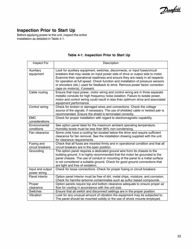
Inspection Prior to Start UpBefore applying power to the unit, inspect the entireinstallation as detailed in Table 4-1.
Inspect For Description
Auxiliary equipment
Look for auxiliary equipment, switches, disconnects, or input fuses/circuit breakers that may reside on input power side of drive or output side to motor. Examine their operational readiness and ensure they are ready in all respects for operation at full speed. Check function and installation of pressure sensors or encoders (etc.) used for feedback to drive. Remove power factor correction caps on motor(s), if present.
Cable routing Ensure that input power, motor wiring and control wiring are in three separate metallic conduits for high frequency noise isolation. Failure to isolate power, motor and control wiring could result in less than optimum drive and associated equipment performance.
Control wiring Check for broken or damaged wires and connections. Check the voltage source of the signals, if necessary. The use of shielded cable or twisted pair is recommended. Ensure the shield is terminated correctly.
EMC considerations
Check for proper installation with regard to electromagnetic capability.
Environmental conditions
See option panel label for the maximum ambient operating temperature. Humidity levels must be less than 95% non-condensing.
Fan clearance Some units have a cooling fan located below the drive and require sufficient clearance for fan removal. See the installation drawing supplied with the unit for clearance requirements.
Fusing and circuit breakers
Check that all fuses are inserted firmly and in operational condition and that all circuit breakers are in the open position.
Grounding The option panel requires a dedicated ground wire from its chassis to the building ground. It is highly recommended that the motor be grounded to the panel chassis. The use of conduit or mounting of the panel to a metal surface is not considered a suitable ground. Check for good ground connections that are tight and free of oxidation.
Input and output power wiring
Check for loose connections. Check for proper fusing or circuit breakers.
Panel interior Option panel interior must be free of dirt, metal chips, moisture, and corrosion. Check for harmful airborne contaminates such as sulfur based compounds.
Proper clearance
Option panels require top and bottom clearance adequate to ensure proper air flow for cooling in accordance with the unit size.
Switches Ensure that all switch and disconnect settings are in the proper position. Vibration Look for any unusual amount of vibration the equipment may be subjected to.
The panel should be mounted solidly or the use of shock mounts employed.
Table 4-1. Inspection Prior to Start Up

24
In the following procedures, changing the equipmentbetween drive mode and bypass mode is required.Changing modes is different for the ECB and EMB.The ECB uses pushbuttons on the drive keypadwhile the EMB uses switches on the front of thepanel. Be familiar with the operation of thesedevices prior to start up.
EQUIPMENT HAZARD!OPTION PANELS CONTAIN DANGEROUS VOLTAGES WHEN CONNECTED
TO LINE VOLTAGE. INSTALLATION, START-UP AND MAINTENANCE
SHOULD BE PERFORMED ONLY BY QUALIFIED PERSONNEL. FAILURE
TO PERFORM INSTALLATION, START-UP AND MAINTENANCE BY
QUALIFIED PERSONNEL ONLY COULD RESULT IN DEATH OR SERIOUS
INJURY.
1. Perform pre-start up procedure.
2. Ensure that all operator devices are inOFF position. Main and drive disconnectswitches on front of electromechanicalbypass panel must be in OFF position.Panel door(s) closed.
3. Keep main disconnect switch in OFFposition and apply voltage to option panel.DO NOT operate drive or bypass at thistime.
4. Confirm input line voltage is balancedwithin 3%. If not, correct input voltageimbalance before proceeding. Repeatprocedure after voltage correction, ifapplicable.
MOTOR START!ENSURE THAT MOTOR, SYSTEM, AND ANY ATTACHED EQUIPMENT IS
READY FOR START. FAILURE TO ENSURE MOTOR, SYSTEM, AND ANY
ATTACHED EQUIPMENT IS READY FOR START COULD RESULT IN
PERSONAL INJURY OR EQUIPMENT DAMAGE.
5. To apply power, turn main disconnect (anddrive disconnect, when applicable) to ONposition. If a bypass is connected, placebypass in drive mode.
6. Enter drive programming data perinstructions in drive instruction manual.
In steps 7 through 11, for a bypass with a contactormotor selection (CMS) option, put the motorselector switch in motor 1 position. Repeat theprocedure for motor 2 with the switch position inmotor 2. For dual motor applications, check bothmotors at same time.
7. Check motor rotation direction in drivecontrol as follows.
a. Put panel in drive mode.
b. Hand start drive at minimum speed(see drive instruction manual fordetails).
c. Confirm directional rotation.
d. If incorrect, stop drive, remove power,and lock out.
e. Reverse connection of any 2 of 3motor leads at terminal. Do not changeincoming power leads.
f. Remove lockout and apply power.
g. Confirm directional rotation.
������
Start Up Procedure
��������

25
8. Check motor rotation direction in bypassas follows.
a. Momentarily bump motor in bypass.
b. Confirm directional rotation.
c. If incorrect, stop drive, remove power,and lock out.
d. Reverse connection of any 2 of 3 inputpower leads at terminal. Do notchange motor leads.
e. Remove lockout and apply power.
f. Confirm directional rotation.
CAUTIONFULL SPEED OPERATION!ENSURE THAT THE MOTOR, SYSTEM, AND ANY ATTACHED EQUIPMENT
IS READY FOR FULL SPEED OPERATION. USER ASSUMES ALL
RESPONSIBILITY FOR ASSURING SYSTEM IS ABLE TO SAFELY RUN AT
FULL SPEED. FAILURE TO ENSURE THAT THE MOTOR, SYSTEM, AND
ANY ATTACHED EQUIPMENT IS READY FOR FULL SPEED OPERATION
COULD RESULT IN EQUIPMENT DAMAGE.
9. Check full load amps in drive mode onmotor terminals.
a. Put unit into drive mode.
b. Check full load amps on motorterminals T1, T2, and T3. Verify motoramps are within drive and motor ratedcurrent and are balanced within 3%. Ifincorrect, see Troubleshooting Sectionin this manual for isolation procedures.
c. Check full load amps on inputterminals L1, L2, and L3. Verify thatcurrent is within FLA of drive andbalanced within 3%. If incorrect, seeTroubleshooting Section in this manualfor isolation procedures.
11. Check full load amps in bypass mode onmotor terminals.
a. Put unit into bypass mode.
b. Check full load amps on terminals T1,T2, and T3. Verify motor amps arewithin motor FLA rated current andbalanced within 3%. If incorrect, seeTroubleshooting Section in this manualfor isolation procedures.
For steps 12-14, see sections 5 and 6 in thismanual for details.
12. Check operation of any optional functionsto confirm they work, as applicable.Options may include run permissive, firemode, common start/stop, or others.
13. Exercise safety circuit and verify that unitstops running.
14. Exercise start/stop circuit and verify that unitstarts and stops with system in auto mode ofoperation.

26
Section 5Electromechanical Bypass (EMB) Operation
Figure 5-1. Customer-side EMB2 Control Card Terminal Connctions
Table 5-1. EMB2 Control Card Terminal Functions
Conn. Term. Input/Output Type Function 1 Input 2 Input
Normally open, dry relay contact Closed when motor can start to run
3 Input 4 Input
Normally open, dry relay contact Closed for remote start with common start/stop
5 Input 6 Input
Normally closed, dry relay contact Safety input, open to stop
7 Input 8 Input
Normally open, dry relay contact Closed to enable Fire Mode
9 Output 10 Output
Normally open, dry relay contact Closed indicates Fire Mode activated
11 Output
X55
12 Output Normally open, dry relay contact Closed indicates Motor 1 selected
Conn. Term. Input/Output Type Function 1 Output 2 Output
Normally open, dry relay contact Closed indicates Motor 2 selected
3 Output 4 Output
Normally open, dry relay contact Closed when panel is in Drive Mode
5 Output 6 Output
Normally open, dry relay contact Closed when panel is in Bypass Mode
7 Output Normally open form C relay contact Open when drive is in Fault Condition 8 Output Common form C relay contact Common for fault relay 9 Output Normally closed form C relay contact Closed when drive is in Fault Condition 10 Input Normally open, dry contact CMS Motor 2, close to select 11 Input Normally open, dry contact CMS common
X56
12 Input Normally open, dry contact CMS Motor 1, close to select Conn. Term. Input/Output Type Function
1 Output X58
2 Output Normally open, dry relay contact Closed indicates run requested
4
3
M4,
M5
CO
NTA
CTO
RS
M1,
M2,
AN
D M
3
1615141312109 116 87A
ND
CM
S S
WIT
CH
MK
103
10 3 4 5217 984 65
MK
106 TE
ST
CO
NN
EC
TOR
ELE
CTR
OM
EC
HA
NIC
AL
3 12
MK
101
6 5 49 7812 10113 12
1 2
MK
100
7 6 510 891 12 112
CU
STO
ME
RC
ON
NE
CTI
ON
S
CU
STO
ME
RC
ON
NE
CTI
ON
S
CO
NTA
CTO
RS BO
AR
D
4321
ON
S10
3
CO
NTA
CT
CLO
SE
D
MO
TOR
ON
BY
PAS
S
MO
TOR
ON
DR
IVE
CO
NTA
CT
CLO
SE
DM
2IN
DIC
ATE
S
IND
ICAT
ES
M3
CO
NTA
CT
CLO
SE
DIN
DIC
ATE
SR
EQ
UE
ST
TO R
UN
CR
9
RL6
CO
NTA
CT
CLO
SE
DIN
DIC
ATE
SFI
RE
MA
NS
OV
ER
RID
E
CU
STO
ME
R S
UP
PLI
ED
RU
N C
ON
TAC
T
DA
MP
ER
EN
D S
WIT
CH
RU
N C
ON
TAC
T
CU
STO
ME
R S
UP
PLI
ED
FIR
EM
AN
S O
VE
RR
IDE
CO
NTA
CT
CO
NTA
CTS
SH
OW
NIN
FA
ULT
PO
SIT
ION
RL2
CU
STO
ME
R S
UP
PLI
ED
X58
X55 X56
S10
5
12
ON
RE
SIS
TIV
E L
OA
D24
VD
C, 1
AM
AX
IMU
M
WIT
H C
MS
WIT
HO
UT
CM
S
AU
TOM
ATIC
BY
PAS
S
TIM
E S
ELE
CT
24 V
DC
, 1 A
RE
SIS
TIV
E L
OA
D
MA
XIM
UM
RE
SIS
TIV
E L
OA
D24
VD
C, 1
AM
AX
IMU
M
JUM
PE
RE
DFA
CTO
RY
INTE
RLO
CK
CU
STO
ME
RS
UP
PLI
ED
SA
FETY
RE
PLA
CE
WIT
H
CO
NTA
CT
CLO
SE
DIN
DIC
ATE
SM
OTO
R 2
SE
LEC
TED
M5
M4
CO
NTA
CT
CLO
SE
DIN
DIC
ATE
SM
OTO
R 1
SE
LEC
TED
CU
STO
ME
R S
UP
PLI
ED
CO
NTA
CT
TOS
ELE
CT
MO
TOR
2
CU
STO
ME
R S
UP
PLI
ED
SE
LEC
T M
OTO
R 1
CO
NTA
CT
TO
RE
SIS
TIV
E L
OA
D24
VD
C, 1
AM
AX
IMU
M
JUM
PE
RE
DFA
CTO
RY

27
Figure 5-2. EMB2 Control Card
Terminal X56
Terminal X55
Terminal X58
Typical Control Connections for Common HVACApplicationsTable 5-2 lists EMB2 default parameter settings forbypass operation. If the drive is reinitialized, be surethat these settings are maintained or reset forproper bypass operation.
Table 5-3 lists common functions for controlling amotor(s) with a bypass and the typical terminalconnections used. Commands enable drivefunctions. Status reports describe conditions but donot enable a function.
Switch S103Autobypass Timer
Table 5-3. Typical HVAC Control Connections
Name Function Drive Terminals
EMB2 X56
EMB2 X55
EMB2 X58
Remote Drive Start (with common start/stop)
Input Command 3, 4
Remote Drive Start (without common start/stop)
Input Command 13, 18
Motor Running on Drive Output Status 04, 05, 06 Run request (for run permissive)
Output Command 1, 2
Run Enable (for run permissive)
Input Command 1, 2
Safety Stop Input Command 5, 6 Drive Fault Output Status 7, 8, 9 Fire Mode Input Command 7, 8 Remote Motor 1 Select Input Command 11, 12 Remote Motor 2 Select Input Command 10, 11 Motor 1 Selected Output Status 11, 12 Motor 2 Selected Output Status 1, 2 Drive Mode Output Status 3, 4 Bypass Mode Output Status 5, 6 Fire Mode Output Status 9, 10
Drive terminal
Parameter number
Parameter name
Value number
Value name Function
01 & 02 540 [0]Relay 1 function
167Start
Command Active
Run Permisive
01 & 02 540 [0]Relay 1 off
delay0.00 seconds Off Delay
Run Permisive
19 511Term 19
digital input52
Run Permisive
Run Permisive
18 510Term 18
digital input8 Start
Common run/stop
27 500Digital I/O
Mode0 PNP
External Interlock
27 501Term 27
Mode0 Input
External Interlock
27 512Term 27
digital input7
External Interlock
External Interlock
29 502Term 29
Mode1 Output Auto bypass
29 531Term 29
digital output160 No Alarm Auto bypass
Table 5-2. EMB2 Parameter Settings

28
EMB(0) and EMB1The electromechanical bypass is available in twoadditional types, the EMB(0) and EMB1. Each hasreduced functionality from the EMB2. The figuresand tables below list for features and functionsavailable in either type. Table 5-6 lists EMB1 defaultparameter settings for bypass operation. If the driveis reinitialized, be sure that these settings aremaintained or reset for proper bypass operation.
See the mechanical layout diagram inside the coverof the unit for connector locations within the unit.
Figure 5-3. EMB(0) Control Connector
Figure 5-4. EMB1 Control Card
Table 5-4. EMB(0) Terminal Functions
Table 5-5. EMB1 Terminal Functions
Conn. Term. Input/Output Type Function
1 NA2 NA3 Input4 Input5 Input6 Input7 NA8 NA9 NA10 NA11 Output12 Output
Conn. Term. Input/Output Type Function1 Output2 Output3 Output4 Output5 Output6 Output7 NA8 NA9 NA10 Input Normally open, dry
contactCMS Motor 2, close to select
11 Input Normally open, dry contact
CMS common
12 Input Normally open, dry contact
CMS Motor 1, close to select
Normally open, dry relay contact
Closed indicates Motor 1 selected
X55
Normally open, dry relay contact
Closed for remote run with common run/stop, close to run
Normally closed, dry relay contact
Safety input, open to stop
Normally open, dry relay contact
Closed when panel is in Drive Mode
Normally open, dry relay contact
Closed when panel is in Bypass Mode
X56
Normally open, dry relay contact
Closed indicates Motor 2 selected
Conn. Term. Input/Output Type Function
1 Input
2 Input3 Common Not for customer use Not for customer use4 Output5 Output6 Output7 Output8 Input Normally open, dry
contactCMS Motor 1, close to select
9 CMS common Normally open, dry contact
CMS common
10 Input Normally open, dry contact
CMS Motor 2, close to select
TB1
Normally closed, dry relay contact
Safety input, open to stop
Normally open, dry auxcontact
Closed when panel is in drive mode
Normally open, dry auxcontact
Closed when panel is in Bypass Mode
Table 5-6. EMB1 Parameter Settings
Drive terminal
Parameter number
Parameter name
Value number
Value name
Function
18 510Term 18
digital input8 Start
Common run/stop
27 500Digital I/O
Mode0 PNP
External Interlock
27 501Term 27
Mode0 Input
External Interlock
27 512Term 27
digital input7
External Interlock
External Interlock
Terminal X56
Terminal X55
Terminal TB1

29
EMB Auto bypass
General InformationAuto bypass allows a fault condition in thedrive to activate running the motor in bypasswithout operator intervention. Activation of thefunction is through setting DIP switches(S103) located on the EMB2 bypass controlcard (see Figure 5-2). A fault condition en-ables a delay timer prior to tripping the driveinto bypass. The fault trip and running inbypass are reported as output from thebypass control card. The auto bypass func-tion is built-in.
Prior to Enabling Auto Bypass• Complete the start-up procedure to
verify motor rotation direction inbypass is correct and that the systemis ready in all respects for continuousfull speed operation in bypass.
HIGH VOLTAGE!REMOVE POWER TO BYPASS PANEL BEFORE SETTING AUTO BYPASS
DIP SWITCH SETTINGS. BYPASS CAN CONTAIN HIGH VOLTAGE.FAILURE TO REMOVE POWER TO BYPASS PANEL BEFORE SETTING
DIP SWITCHES COULD CAUSE PERSONAL INJURY OR DEATH.
Operation• With the bypass selector switch in
drive and auto bypass enabled, a faultsignal from the drive will activate theauto bypass timer.
• If the fault clears before the time delayis complete, the motor remains oper-ating in drive mode. This allowstemporary faults, such as a momen-tary under or over voltage, to clearwithout transferring the system tobypass.
• If the timer completes its cycle beforethe fault clears, the panel trips intobypass mode and the motor runs atconstant full speed from line inputvoltage.
• In bypass, the motor will stop if safetyor motor overload conditions areexceeded.
• Once auto bypass is activated, theonly way to reset the unit back to driveis by operator intervention. Ensure thatthe fault has been cleared, then rotatethe bypass switch to the OFF positionmomentarily before setting it back tothe drive position. This resets thedrive and fault timer.
Auto Bypass Function SetupEnable auto bypass by closing one or moreDIP switches on switch S103 located on thebypass control card. (Times are approxi-mate.)
• All OFF = no auto bypass operation• 1-3 ON = 15 second delay (minimum)• Switch 1 only ON = 30 sec. delay• Switch 2 only ON = 60 sec. delay• Switch 3 only ON = 300 sec. delay
(maximum)• Switch 4 = Always OFF
��������

30
EMB Common Run/Stop
General InformationThe common run/stop function providesremote run and stop control of the motor(s) inbypass. Without common run/stop, the motorwould automatically run at full speed when-ever the bypass is activated. The remotesignal provides drive control as well asbypass control, making this one input com-mon to both. Common run/stop is enabled byfactory default. When used with the run per-missive function, common run/stop permitsrun request operation in bypass.
Prior to Enabling Common Run/Stop• Complete the start-up procedure to
verify motor rotation direction inbypass is correct and that the systemis ready in all respects for continuousfull speed operation in bypass.
Operation• A user supplied remote start
command wired to connector X55,terminals 3 and 4 initiates remotebypass operation. With common run/stop, bypass mode cannot beactivated by hand on the drive keypador by serial communication.
Common Run/Stop Setup• Wire input terminals 3 and 4 on
connector X55 per the systemapplication.
To Disable Common Run/Stop• Common run/stop is enabled by
factory default when ordered.• To disable the feature, jumper termi-
nals 3 and 4 on connector X55. Thisallows the bypass to start when thebypass switch is placed in the bypassposition.
• Remove red wire from terminal 18 ofthe drive control terminal and insulatethe end of the wire to prevent shorting.This is required or the drive will alwayshave a run command.
• If applicable, connect remote run/stopinput to terminals 12 and 18 in thedrive.

31
EMB Run Permissive
General InformationRun permissive allows a remote signal tonotify the drive to start, indicating the systemis safe to operate. Run permissive works indrive or bypass mode. Run permissive isdisabled by factory default when ordered by ajumper wire on connector X58 betweenterminals 1 and 2.
Prior to Enabling Run Permissive• Complete the start-up procedure to
verify motor rotation direction inbypass is correct and that the systemis ready in all respects for continuousfull speed operation in bypass.
• Verify that the drive is programmed forthe run permissive function. See thedrive support materials for program-ming the run permissive function.
Operation• A start command can be from local
hand start on the drive keypad or aremote auto start signal through digitalinput connector X55, terminals 3 and4, or the serial communications input.
• In response to a start command, anoutput request is sent from X58 termi-nals 1 and 2 to the external equipment(to activate a valve or damper, forexample).
• When a return run signal on X55terminals 1 and 2 is received, themotor is started in either drive orbypass mode, depending upon thebypass switch position.
Run Permissive Function Setup• Remove factory-installed jumper wire
on connector X55, terminals 1 and 2.• Wire the output run request to connec-
tor X58, terminals 1 and 2.• Wire the input run permission to
connector X55, terminals 1 and 2 perthe system application.
Disable Run Permissive• Run permissive is enabled by factory
default when ordered.• To disable the run permissive function,
jumper between terminals 1 and 2 onconnector X55.

32
EMB Overload
General InformationThe overload device provides overcurrentprotection for the motor when running inbypass. The thermally activated overloadmonitors motor current and trips to removepower to the motor if a sustained overcurrentcondition exists. A Class 20 overload isstandard with a variable setting for motorcurrent. Test and reset buttons are alsoprovided. In drive mode, the drive providescurrent sensing and trip protection. Fusesprovide quick action for high over currentconditions.
Prior to Enabling Overload• Verify that the overload current dial
setting matches the motor FLA ratingon the motor nameplate.
• If the motor FLA is greater or less thanrange of the current dial, reconfirm thatthe motor hp and voltage are withinthe option panel (and drive) rating. Ifless than the FLA rating, replace theoverload with the correct size. Ifgreater than the FLA rating, replacethe panel with one of a proper rating.
CAUTIONMOTOR DAMAGE!REPEATED ATTEMPTS TO RESET OVERLOAD CAN CAUSE MOTOR
DAMAGE. CORRECT OVERLOAD CONDITION AND LET OVERLOAD
AND MOTOR RETURN TO NORMAL OPERATING TEMPERATURE BEFORE
RESETTING. SEE MOTOR MANUFACTURER’S RECOMMENDATIONS FOR
TIME BETWEEN START ATTEMPTS. FAILURE TO CORRECT OVERLOAD
CONDITION AND LET MOTOR RETURN TO NORMAL OPERATING
TEMPERATURE COULD CAUSE MOTOR DAMAGE.
OperationOverloads are rated by class. The class isdefined by the NEC to determine the maxi-mum time to trip. A Class 20 overload, forexample, has a typical trip delay of 20 sec-onds or less at 600% current and normaloperating temperature. This allows for high
Figure 5-5. Sample Overload Device
motor inrush current for 20 seconds while themotor is ramping up to synchronous speed.The trip time, however, is based on thepercentage of overload. The higher theoverload, the shorter the trip time. It is impor-tant that the overload class not exceed themotor class rating or motor damage couldoccur. For dual motor operation, an overloadis provided for each motor. For contact motorselect, one overload is provided and moni-tors either motor when selected.
Overload Function Setup• Set the overload current dial to the
FLA of the motor. DO NOT add theservice factor of the motor into thesetting. A service factor of 120% forClass 20 is designed into the over-load.
• Pressing the test pushbutton verifiesthe operation of the overload. Theoverload should trip when pressed.Use the reset pushbutton to reset theoverload after test.
• Reset is used to reset the overloadafter it trips. If the overload is still hot,wait until the motor reaches normaloperating temperature before reset-ting. The overload offers a manual(hand) or auto reset selection. It ishighly recommended to operate in themanual factory setting to prevent therisk of damage to the motor.
T1 T2 T3
97NO 98NO 95NC 96NC
2528 32
RESETTEST
MANUAL
AUTO
TRIP
Class 20
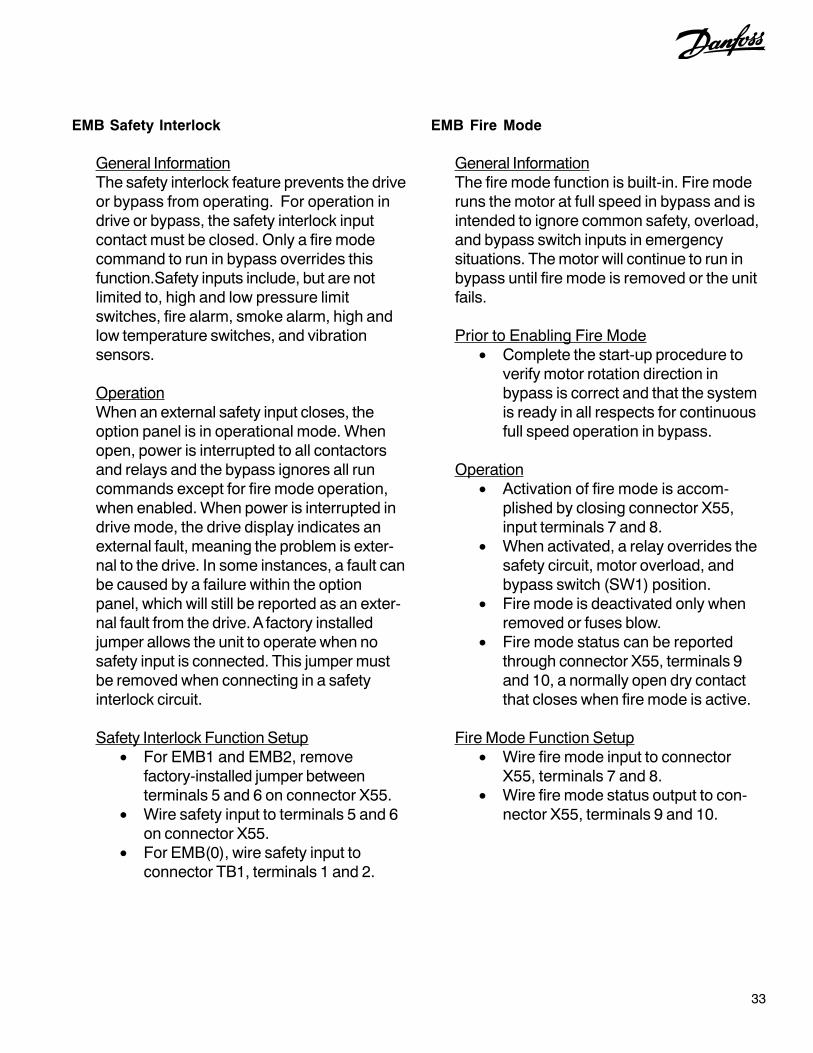
33
EMB Fire Mode
General InformationThe fire mode function is built-in. Fire moderuns the motor at full speed in bypass and isintended to ignore common safety, overload,and bypass switch inputs in emergencysituations. The motor will continue to run inbypass until fire mode is removed or the unitfails.
Prior to Enabling Fire Mode• Complete the start-up procedure to
verify motor rotation direction inbypass is correct and that the systemis ready in all respects for continuousfull speed operation in bypass.
Operation• Activation of fire mode is accom-
plished by closing connector X55,input terminals 7 and 8.
• When activated, a relay overrides thesafety circuit, motor overload, andbypass switch (SW1) position.
• Fire mode is deactivated only whenremoved or fuses blow.
• Fire mode status can be reportedthrough connector X55, terminals 9and 10, a normally open dry contactthat closes when fire mode is active.
Fire Mode Function Setup• Wire fire mode input to connector
X55, terminals 7 and 8.• Wire fire mode status output to con-
nector X55, terminals 9 and 10.
EMB Safety Interlock
General InformationThe safety interlock feature prevents the driveor bypass from operating. For operation indrive or bypass, the safety interlock inputcontact must be closed. Only a fire modecommand to run in bypass overrides thisfunction.Safety inputs include, but are notlimited to, high and low pressure limitswitches, fire alarm, smoke alarm, high andlow temperature switches, and vibrationsensors.
OperationWhen an external safety input closes, theoption panel is in operational mode. Whenopen, power is interrupted to all contactorsand relays and the bypass ignores all runcommands except for fire mode operation,when enabled. When power is interrupted indrive mode, the drive display indicates anexternal fault, meaning the problem is exter-nal to the drive. In some instances, a fault canbe caused by a failure within the optionpanel, which will still be reported as an exter-nal fault from the drive. A factory installedjumper allows the unit to operate when nosafety input is connected. This jumper mustbe removed when connecting in a safetyinterlock circuit.
Safety Interlock Function Setup• For EMB1 and EMB2, remove
factory-installed jumper betweenterminals 5 and 6 on connector X55.
• Wire safety input to terminals 5 and 6on connector X55.
• For EMB(0), wire safety input toconnector TB1, terminals 1 and 2.

34
EMB Fault Reporting
General InformationA fault indication is provided if the driveexperiences a fault or bypass input power islost. The EMB2 bypass control card monitorsthe drive fault output for status reporting. Thefault contacts are fail-safe, meaning that ifpower is removed a fault condition is auto-matically reported. Fault status is not moni-tored in bypass operation.
OperationFor the EMB2, fault reporting is monitoredthrough a Form-C relay (RL2) on the bypasscontrol board. The relay reports a fault onconnector X56 terminals 7, 8, and 9. Innormal operation, the relay is powered andterminal 7 is closed with terminal 9 open. In afault condition, power to the relay is lost andthe relay positions automatically reverse,signaling the fault condition. Terminal 8 is thecommon to both. For the EMB(0) or EMB1,drive terminals 1 (common), 2 and 3 reportfaults with 2 open and 3 closed in the faultcondition.
Fault Reporting Function Setup• For EMB2, fault reporting status is
connected to connector X56, outputterminals 7, 8, and 9.
• For EMB(0) or EMB1, fault reportingstatus is connected to drive outputterminals 1, 2, and 3.
EMB Switches
Bypass selector switch. The bypassselector switch is used for either the 2-contactor or 3-contactor bypass.
• 2-contactor bypass. A panel-mounted Drive/OFF/Bypass selectorswitch is used to electrically selectwhether the motor is driven by thedrive (M2 contactor), connected to thefull-speed bypass (M3 contactor), ordisconnected from both. See Figure1-1.
• 3-contactor bypass. A panel-mounted Drive/OFF/Bypass/Testselector switch is used to electricallyselect whether the motor is controlledby the drive (M1 and M2 contactors),connected to the full-speed bypass(M3 contactor), or disconnected fromboth. The test position allows foroperation in bypass while stillproviding power to the drive (M1 andM3). See Figure 1-1.

35
Section 6Electronically Controlled Bypass (ECB) Operation
Figure 6-1. Local Control Panel (LCP)
OverviewInformation provided in this section is intended toenable the user to connect control wiring, programfunctions, and operate the ECB and its optionalfeatures.
The ECB contains a local processor located on theECB control card which interacts with the drive’scontrol logic for programmable options, remotecommand input, and output status reporting. Ratherthan panel-mounted operator-activated selectorswitches, as on the electromechanical option panel,ECB control is provided by the drive’s processor.
The ECB also contains a power supply whichprovides back up for the drive’s logic circuitry, soeven if the drive loses power, the control andcommunication functions are maintained.
Programming and display are provided by thedrive’s local control panel (LCP). See Figure 6-1. Animportant feature of the ECB is the ability to acceptcommands from a building automation system(BAS) and to report operational status in return.
Control wiring connections are made to either thedrive’s control terminals (see Figure 6-2) orterminals provided on the ECB control card (seeFigure 6-3). Drive analog and digital I/O terminalsare multifunctional and need to be programmed fortheir intended use while the terminals on the ECBcontrol card are dedicated for specific functions.
Programming options for drive terminals are seenby pressing the MAIN MENU key or QUICK MENUkey on the LCP keypad. Parameter menus appearin the LCP display. The arrow keys are used fornavigating through the parameter lists. Terminalfunctions are programmed in the 5-00 parametergroup. (See Table 6-1 for factory default parametersettings for drives with an ECB.) Bypass functionsare programmed in the 31-00 parameter group (seeTable 6-5). See the drive’s supporting materials fordetailed programming instructions.
LCP display
Menu keys
Menu navigation
Control keys
ParameterParameter
nameSetting title Setting Function
5-01Term 27
ModeInput 0
Customer Interlock
5-02Term 29
ModeOutput 1 Auto bypass
5-10Term 18
digital inputStart 8
Common run/stop
5-11Term 19
digital inputRun
Permissive52
Run Permissive
5-12Term 27
digital inputExternal Interlock
7Customer Interlock
5-31Term 29
digital outputNo Alarm 160 Auto bypass
5-40[0]Relay 1 function
Start Command
Active167
Run Permissive
5-40[0]Relay 1 off
delayOff Delay 0.00 s
Run Permissive
Table 6-1. 5-00 Parameter Group FactoryDefault Settings
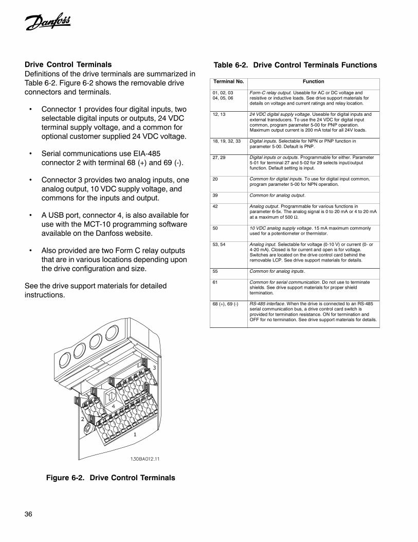
36
Drive Control TerminalsDefinitions of the drive terminals are summarized inTable 6-2. Figure 6-2 shows the removable driveconnectors and terminals.
• Connector 1 provides four digital inputs, twoselectable digital inputs or outputs, 24 VDCterminal supply voltage, and a common foroptional customer supplied 24 VDC voltage.
• Serial communications use EIA-485connector 2 with terminal 68 (+) and 69 (-).
• Connector 3 provides two analog inputs, oneanalog output, 10 VDC supply voltage, andcommons for the inputs and output.
• A USB port, connector 4, is also available foruse with the MCT-10 programming softwareavailable on the Danfoss website.
• Also provided are two Form C relay outputsthat are in various locations depending uponthe drive configuration and size.
See the drive support materials for detailedinstructions.
Figure 6-2. Drive Control Terminals
Table 6-2. Drive Control Terminals Functions
Terminal No. Function
01, 02, 03 04, 05, 06
Form-C relay output. Useable for AC or DC voltage and resistive or inductive loads. See drive support materials for details on voltage and current ratings and relay location.
12, 13 24 VDC digital supply voltage. Useable for digital inputs and external transducers. To use the 24 VDC for digital input common, program parameter 5-00 for PNP operation. Maximum output current is 200 mA total for all 24V loads.
18, 19, 32, 33 Digital inputs. Selectable for NPN or PNP function in parameter 5-00. Default is PNP.
27, 29 Digital inputs or outputs. Programmable for either. Parameter 5-01 for terminal 27 and 5-02 for 29 selects input/outputfunction. Default setting is input.
20 Common for digital inputs. To use for digital input common, program parameter 5-00 for NPN operation.
39 Common for analog output.
42 Analog output. Programmable for various functions in parameter 6-5x. The analog signal is 0 to 20 mA or 4 to 20 mA at a maximum of 500 Ω.
50 10 VDC analog supply voltage. 15 mA maximum commonly used for a potentiometer or thermistor.
53, 54 Analog input. Selectable for voltage (0-10 V) or current (0- or 4-20 mA). Closed is for current and open is for voltage. Switches are located on the drive control card behind the removable LCP. See drive support materials for details.
55 Common for analog inputs.
61 Common for serial communication. Do not use to terminate shields. See drive support materials for proper shield termination.
68 (+), 69 (-)
RS-485 interface. When the drive is connected to an RS-485 serial communication bus, a drive control card switch is provided for termination resistance. ON for termination and OFF for no termination. See drive support materials for details.

37
ECB Control CardThe ECB control card (Figure 6-3) provides inputconnector X57 for commanding bypass operationremotely and output connector X59 for reporting thebypass mode of operation, either drive mode orrunning in bypass.
See Table 6-3 for ECB control card terminal typesand functions.
Figure 6-3. ECB Control Card Terminal Connections
TerminalX57
TerminalX59
TerminalX56
TerminalX58
BYPASS MODE
O.L. RESETSUPPLIED
CUSTOMER
(A2)
(A2)
LOADCONNECTIONCUSTOMER
DRIVE MODE
MODE ENABLEBYPASSSUPPLIED
CUSTOMER
CUSTOMERCONNECTION
OVERRIDE
SUPPLIEDCUSTOMER
MANUALBYPASS
11
11
MK 110
CMS MOTOR SELECTED
BYPASS MODE ENABLE
TEST CONNECTOR
LOAD7
8
NC 4
5
6
NC 3
1
2
8
9
10
BYPASS MODE
DRIVE MODE
COM
COM
BYPASS OVERRIDE
O.L. RESET
COM
COM
(95)(96)
M3
M2
OL14
19
20
21
5
6
7
2
3
1
M2(A1)
18
NC
NC
11
12
10
NC
NC
16 8
7
9
SAFTY INTERLOCK
M3 STATUS
M2 STATUS
O.L. TRIP
COM
+ 24 V
+ 24 V
40 mA MAX24 VDC
BOARDX58
CUSTOMER
CONTACT
MOTORRUNNING
M3(A1)
NC
NC
15
4
5
6
NC
2
1
3
11
101
2
MAXIMUM 1 AMPS DC RESISTIVE
0-24 VDC
+ 24 V
24 V SUPPLYEXTERNAL
ECB
(A2) (A1)M1
17
(13) (14)
(13) (14)
X56
X57
X59
M5
23
22
M4
(95)(96)OL2
36
NC

38
Table 6-3. ECB Card Terminals
Input Conn.
Term. Function Type
1 Digital input for safety stop User supplied dry contact 2 Common User supplied dry contact 3 Factory use only 4 No function 5 Factory use only 6 Factory use only 7 Factory use only 8 Digital input for remote bypass enable User supplied dry contact 9 Digital input overrides system to
Bypass Mode ignoring all other inputs and commands, except for safety stop on terminal 1.
User supplied dry contact
X57
10 Digital input for remote overload reset User supplied dry contact Output Conn.
Term. Function
1 Common for binary I/O 2 Common for binary I/O 3 No function 4 No function 5 Digital output indicates panel is in
Drive Mode. 24 VDC digital output
6 Digital output indicates panel is in Bypass Mode
24 VDC digital output
7 Common for binary I/O
X59
8 Common for binary I/O Relay Output
Term. Function
1 N.O. contact for running in bypass or drive
Relay output for user
2 N.O. contact for running in bypass or drive
Relay output for user. X56
3 - 12 Factory use only

39
ECB Drive or Bypass SelectionUse the drive keypad and display to switch betweenthe motor running in drive mode or bypass whenoperating in local control. The display in operatingmode is shown below.
1. Press DRIVE BYPASS key. Displaychanges to show bypass and drive modeoptions (shown in Step 2).
Drive/Bypass Option Key
Display
2. When running in drive mode, press OKkey on keypad to activate bypass mode orpress CANCEL to remain in drive mode. Inbypass, motor will run at full speed.
5. Press STATUS key to return to drivestatus display.
2. When running in bypass mode, press OKkey on keypad to activate drive mode orpress CANCEL to remain in bypass mode.
Info Key
NOTEPRESSING THE INFO KEY AT ANY TIME DISPLAYS TIPS AND
GUIDELINES FOR PERFORMING THE FUNCTION CURRENTLY ACTIVATED.
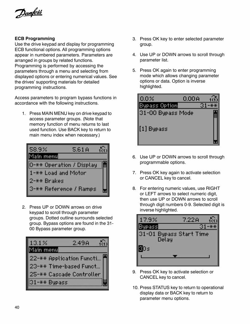
40
ECB ProgrammingUse the drive keypad and display for programmingECB functional options. All programming optionsappear in numbered parameters. Parameters arearranged in groups by related functions.Programming is performed by accessing theparameters through a menu and selecting fromdisplayed options or entering numerical values. Seethe drives’ supporting materials for detailedprogramming instructions.
Access parameters to program bypass functions inaccordance with the following instructions.
1. Press MAIN MENU key on drive keypad toaccess parameter groups. (Note thatmemory function of menu returns to lastused function. Use BACK key to return tomain menu index when necessary.)
2. Press UP or DOWN arrows on drivekeypad to scroll through parametergroups. Dotted outline surrounds selectedgroup. Bypass options are found in the 31-00 Bypass parameter group.
3. Press OK key to enter selected parametergroup.
4. Use UP or DOWN arrows to scroll throughparameter list.
5. Press OK again to enter programmingmode which allows changing parameteroptions or data. Option is inversehighlighted.
6. Use UP or DOWN arrows to scroll throughprogrammable options.
7. Press OK key again to activate selectionor CANCEL key to cancel.
8. For entering numeric values, use RIGHTor LEFT arrows to select numeric digit,then use UP or DOWN arrows to scrollthrough digit numbers 0-9. Selected digit isinverse highlighted.
9. Press OK key to activate selection orCANCEL key to cancel.
10. Press STATUS key to return to operationaldisplay data or BACK key to return toparameter menu options.

41
ECB Hand/OFF/Auto
General InformationThe HAND ON, OFF RESET, and AUTO ONkeys on the drive keypad control both thedrive and bypass (see Figure 6-1). TheDRIVE BYPASS key allows the user to locallyselect drive or bypass mode of operation. Itdoes not necessarily start or stop the motor.
Prior to Enabling Hand/Off/Auto• Complete the start-up procedure to
verify motor rotation direction inbypass is correct and that the systemis ready in all respects for continuousfull speed operation in bypass.
Programming Key FunctionsFor the OFF RESET and DRIVE BYPASSkeys, the table below lists the parametersthat select functions for the control keys. Apassword protection can also be assigned inthese parameters.
Operation• HAND ON allows the user to start the
motor locally from the keypad. Pressthe HAND ON to start the motor locallyeither in drive or bypass mode.
• OFF RESET allows the user to stopthe motor locally from the keypad.Press the OFF RESET to stop themotor locally, either in drive or bypassmode.
• AUTO ON allows the motor to bestarted remotely from digital input orserial communications. Press AUTOON to activate remote motor start andstop from a digital input or serialcommunications in drive or bypassmode.
• Press the DRIVE BYPASS key toinitiate the display to toggle betweendrive or bypass mode of operation.Press the OK key to accept thechange or CANCEL key to cancel theaction.
Table 6-4. LCP Control Keys Programming
Parameter number Key Function
00-44 Off / Reset This disables or enables the [Off / Reset] key on LCP.
(0) disabled, (1) enabled, (2) password Default value is (1) enabled.
00-45 Drive / Bypass This disables or enables the [Drive Bypass] key on LCP.
(0) disabled, (1) enabled, (2) password Default value is (1) enabled.

42
ECB Mode of Operation
General InformationThe ECB has four modes of operation: drive,bypass, auto bypass, and test. The mode isselected through the drive keypad and dis-play. Bypass mode select can be accesseddirectly by pressing the DRIVE/BYPASS keyon the keypad.
Prior to Enabling Mode of Operation• Complete the start-up procedure and
verify motor rotation direction in by-pass is correct and that the system isready in all respects for continuous fullspeed operation in bypass.
• Press the OFF/RESET key on the drivekeypad to prevent operation of the motor.
OperationDrive mode. The motor is connected to andcontrolled by the drive. Contactors M1 (op-tional) and M2 are closed while contactor M3is open. (Contactor M1 for test mode is onlypresent in the 3-contactor configuration.) Themotor will not run until a run command ispresent.
Bypass mode. The motor operates at fullspeed across the line when a run commandis present. Contactor M3 is closed and M1(optional) and M2 are open.
Test mode. Test mode puts the panel intobypass mode and will automatically run inbypass. Contactor M1 is closed supplyingpower to the drive for test purposes while M2is open. Contactor M3 controls the operationof the motor in bypass, closed to run themotor, open to remove power. The controlkeys on the drive keypad will not control thebypass until test mode is removed.
Auto bypass mode. When in drive mode,auto bypass is a timed interval that allows afault condition in the drive to activate runningthe motor in bypass without operator inter-vention.
Mode of Operation Select• Mode of operation is programmed
through the 31-00 parameter group.See Table 6-5 below.
Table 6-5. Bypass Parameter Functions
Parameter Number Selection Function Selects source of motor power.
(0) Drive (drive mode) 31-00 Bypass Mode
(1) Bypass (bypass mode) Sets a delay time for starting in bypass that allows for external actions to take place prior to line starting the motor. 31-01
Bypass Start Time Delay
0-60 Seconds (default value is 5 seconds) Setting a value other than 0 seconds enables auto bypass. Bypass trip delay sets the delay time before switching to bypass mode when the drive has a fault.
31-02
Bypass Trip Time Delay
0-300 seconds (default is 0 seconds = OFF) Setting to enabled puts bypass in test mode. See manual for warnings and cautions.
(0) disabled (default value) 31-03
Test Mode Activation
(1) enabled Read only display which shows the bypass status in hex. See Table 6-6 for details. 31-10
Bypass Status Word
0, 216-1 (default value is 0)
31-11 Bypass Running Hours
Read only display which shows bypass running hours.

43
Table 6-6. Parameter 31-10 Bypass Status Word Bit Definitions
Bit Description
0Test Mode The Test Mode bit will be true when the ECB is in Test Mode.
1Drive Mode The Drive Mode bit will be true when the ECB is in Drive Mode.
2Automatic Bypass Mode The Automatic Bypass Mode bit will be true when the ECB is in Automatic Bypass Mode.
3Bypass Mode The Bypass Mode bit will be true when the ECB is in Bypass Mode.
4Reserved This bit is reserved for future use.
5Motor Running from Bypass/Drive The Motor Running from Bypass/Drive Bit will be true when the motor is running from either the drive or the bypass.
6Overload Trip The Overload Trip Bit will be true when the ECB detects an overload trip.
7M2 Contactor Fault The Contactor Fault Bit will be true when an M2 Contactor Fault is detected.
8M3 Contactor Fault The Contactor Fault Bit will be true when an M3 Contactor Fault is detected.
9 External Interlock The External Interlock Bit will be true when an External Interlock fault is detected.
10Manual Bypass Override The Manual Bypass Override Bit will be true when the Manual Bypass Override input is true.
Bypass Status Word Bit Examples1. Motor running and bypass in drive mode.Status word 22 hexadecimal converts to 00000100010 binary.
Bit 10 9 8 7 6 5 4 3 2 1 0 Binary 0 0 0 0 0 1 0 0 0 1 0
2. External interlock fault (open) and bypass in bypass mode.Status word 208 hexadecimal converts to 01000001000 binary.
Bit 10 9 8 7 6 5 4 3 2 1 0 Binary 0 1 0 0 0 0 0 1 0 0 0

44
ECB Auto Bypass
General InformationAuto bypass allows a fault condition in the driveto activate running the motor in bypass withoutoperator intervention. Activation of the functionis through setting timer start parameters in thedrive programming. Fault trip and running inbypass are reported through the drive display,digital outputs, and serial communications. Inaddition, the independently powered ECB cardis available to report bypass status when thedrive is inoperable (control card operative)through its serial communications or digitaloutputs.
Prior to Enabling Auto Bypass• Complete the start-up procedure to
verify motor rotation direction in bypassis correct and that the system is readyin all respects for continuous full speedoperation in bypass.
Operation• With the auto bypass function enabled,
a fault signal from the drive activates theauto bypass timer.
• If the fault clears before the time delay iscomplete, the motor remains operatingin drive mode. This allows temporaryfaults, such as a momentary under orover voltage, to clear without transferringthe system to bypass.
• If the timer completes its cycle beforethe fault clears, the panel trips intobypass mode and the motor runs atconstant full speed from line inputvoltage.
• In bypass, the motor will stop:- if the drive receives a remote
stop command- local stop (OFF key) on the
drive keypad is pressed- a remote start command is
removed- a safety is open- motor overload is tripped
• Once auto bypass is activated, the onlyway to reset the unit back to drive modeis by operator intervention. Ensure thatthe fault has been cleared, then pressthe BYPASS key on the drive keypadand select drive mode.
Auto Bypass Function SetupEnable auto bypass by changing parameters ingroup 31 in the drive extended menu.
• 31-01, Bypass start time delay. Settingthe timer at anything other than 0 timeactivates start delay in bypass. Leave at30 second default or set as desired upto 60 seconds.
• 31-02, Bypass trip time delay. Settingthe timer at anything other than 0 timeactivates auto bypass. Leave at 5second default or set as desired up to60 seconds.
Parameter 31-02 Bypass Trip Time Delay
Drive Display with Bypass Start Time DelayActive

45
ECB Run Permissive
General InformationWith run permissive active, the drive sends arun request and waits for a remote responseto before notifying the motor to start. Theresponse indicates the system is safe tooperate. Run permissive operates from thekeypad hand/off/auto select in drive or by-pass mode. Run permissive is enabled byprogramming in the drive parameters.
Prior to Enabling Run Permissive• Complete the start-up procedure to
verify motor rotation direction inbypass is correct and that the systemis ready in all respects for continuousfull speed operation in bypass.
• Verify that the drive is programmed forthe run permissive function. See thedrive support materials for program-ming the run permissive function.
Operation• A start command can be initiated from
local hand start, serial communica-tions, or a remote auto start signalthrough digital drive input terminals.
• In response to the start command, anoutput request is sent from the pro-grammable drive relay to the externalequipment (to activate a valve ordamper, for example).
• When a return run signal on the digitalinput is received, the motor is startedin either drive or bypass, dependingupon which mode is active.
Run Permissive Function Setup• See the drive manual or support
materials for programming and wiringto the drive control terminals.
• Wire the output run request to thedrive output terminals selected, andprogram the terminals for run request.
• Wire the input run command to thedrive input terminals selected, andprogram the terminals for run permis-sive.
Disable Run Permissive• Disable run permissive through the
drive parameters and terminal pro-gramming.

46
Figure 6-4. Sample Overload Device
ECB Overload
General InformationAn overload device provides overcurrentprotection for the motor when running in by-pass. The thermally activated overload moni-tors motor current and trips to remove power tothe motor if a sustained overcurrent conditionexists. A Class 20 overload is standard with avariable setting for motor current. Test and resetbuttons are also provided. In drive mode, thedrive provides current sensing and trip protec-tion. Fuses provide quick action for high overcurrent conditions.
Prior to Enabling Overload• Verify that the overload current dial
setting matches the motor FLA ratingon the motor nameplate.
• If the motor FLA is greater or less thanrange of the current dial, reconfirm thatthe motor hp and voltage are withinthe option panel (and drive) rating. Ifless than the FLA rating, replace theoverload with the correct size. Ifgreater than the FLA rating, replacethe panel with one of a proper rating.
CAUTIONMOTOR DAMAGE!REPEATED ATTEMPTS TO RESET OVERLOAD CAN CAUSE MOTOR
DAMAGE. CORRECT OVERLOAD CONDITION AND LET OVERLOAD
AND MOTOR RETURN TO NORMAL OPERATING TEMPERATURE BEFORE
RESETTING. SEE MOTOR MANUFACTURER’S RECOMMENDATIONS FOR
TIME BETWEEN START ATTEMPTS. FAILURE TO CORRECT OVERLOAD
CONDITION AND LET MOTOR RETURN TO NORMAL OPERATING
TEMPERATURE COULD CAUSE MOTOR DAMAGE.
OperationOverloads and motors are both rated by class.The class is defined by the NEC to determinethe maximum time to trip. A Class 20 overload,for example, has a typical trip delay of 20seconds or less at 600% current and normal
operating temperature. This allows for highmotor inrush current for 20 seconds while themotor is ramping up to synchronous speed.The trip time, however, is based on thepercentage of overload. The higher theoverload, the shorter the time.
Overload Function Setup• Set the overload current dial to the
FLA of the motor. DO NOT add theservice factor of the motor into thesetting. A service factor of 1.2 x FLA isdesigned into the overload.
• Pressing the test pushbutton verifiesthe operation of the overload. Theoverload should trip when pressed.Use the reset pushbutton to reset theoverload after test.
• Reset is used to reset the overloadafter it trips. If the overload is still hot,wait until the motor reaches normaloperating temperature before reset-ting. The overload offers a manual(hand) or auto reset selection. It ishighly recommended to operate in themanual factory setting to prevent therisk of damage to the motor.
T1 T2 T3
97NO 98NO 95NC 96NC
2528 32
RESETTEST
MANUAL
AUTO
TRIP
Class 20

47
ECB Safety Interlock
General InformationThe safety interlock feature prevents the driveor bypass from operating. Only a fire modecommand to run overrides this function. Foroperation in drive or bypass mode, the safetyexternal interlock input contact must beclosed. External inputs include, but are notlimited to, high and low pressure limitswitches, fire alarm, smoke alarm, high andlow temperature switches, and vibrationsensors.
OperationWhen an external safety input closes on ECBterminals 1 and 2 on connector X57, theoption panel is in operational mode. Whenopen, power to the motor is disabled. Thebypass ignores all run commands except forfire mode operation, when applicable. Thedrive display indicates alarm 221, bypassinterlock, meaning the problem is external tothe drive. A factory installed jumper betweenX57 terminals 1 and 2 allows the unit tooperate when no safety input is connected.This jumper must be removed when connect-ing in a safety interlock circuit.
Safety Interlock Function Setup• Remove factory-installed jumper
between ECB connector X57 termi-nals 1 and 2 on drive control terminals.
• Wire safety input to connector X57terminals 1 and 2.
• For technicians familiar with connect-ing to drive terminals 12 and 27 forsafety interlock, be aware that ECBbypass operation will NOT stop withthe external fault report. Use terminals1 and 2 on connector X57, as indi-cated, for bypass control.
ECB Common Run/Stop
General InformationThe common run/stop function providesremote run and stop control of the motor(s)while in either drive or bypass. Withoutcommon run/stop, the motor would automati-cally run at full speed whenever the bypass isactivated. The remote signal provides drivecontrol as well as bypass control, making thisone input common to both. Common run/stopis enabled by factory default. When used withthe run permissive function, common run/stoppermits run request operation in bypass.
OperationA user supplied remote run command wiredto drive terminals 13 and 18 initiates remotedrive or bypass operation. Common run/stopcan also be activated by hand on the drivekeypad or through serial communication.Operation in either drive or bypass is deter-mined by drive or bypass mode selection, notthe run/stop command.
Prior to Enabling Common Run/Stop• Complete the start-up procedure to
verify motor rotation direction inbypass is correct and that the systemis ready in all respects for continuousfull speed operation in bypass.
Common Run/Stop Setup• Wire a remote run/stop to drive input
terminals 13 and 18 (default run input).Ensure that parameter 18 is pro-grammed for run (default setting).

48
ECB Fault Reporting
General InformationThe ECB monitors bypass contactors M2and M3 and reports failures to the drive fordisplay and external reporting. The drive alsomonitors the ECB card for bypasscommunication errors.
OperationECB detected faults are reported by the drivein three ways: warnings and alarms aredisplayed on the keypad display, throughserial communication, or through outputrelays. The drive provides a form-C fault relayon terminals 01, 02, and 03. The faultcontacts are fail-safe, meaning that if poweris removed the contacts close and a faultcondition is reported.
The drive monitors the ECB card communi-cation and detects when communicationstops. An ECB card failure or communicationerror could cause this. Contact Danfossusing the phone number on the back of thismanual for technical support if this happens.
Fault Reporting Function Setup• Automatic function. No set up
required.
ECB Advanced Fire Mode
General InformationDrive operation in advanced fire mode isprogrammable. In the event the drive doesnot function, the motor is operated in bypassat full speed. Fire mode is intended to ignorecommon safety and overload inputs in emer-gency situations. The fire mode function isbuilt-in. See the drive support materials forprogrammable options.
Prior to Enabling Fire Mode• Complete the start-up procedure to
verify motor rotation direction inbypass is correct and that the systemis ready in all respects for continuousfull speed operation in bypass.
• Verify that the drive is programmed forthe fire mode function. See the drivesupport materials for programming thefire mode function.
Operation• Activation of fire mode is accom-
plished by programming the drive forfire mode.
• When activated, the ECB ignoressafety circuits and motor overload.
• Fire mode is deactivated only whenremoved or fuses blow.
• Fire mode status can be reportedthrough serial communications ordrive output.
Fire Mode Function Setup• Program drive for fire mode.• If required, program a drive output for
fire mode status.• See the drive support materials for
programming the fire mode function.

49
Section 7Non-bypass Component Functions
Power Fusing
For all option panel power fuses, use the specifiedfuse or an equivalent replacement only. See thefuse ratings label on the inside cover of the unit foroption panel fuse ratings.
Main fusing. Main fuses are located ahead of thedrive and bypass. Main fuses are designed toprotect the circuitry within the bypass panel but isnot adequate to protect the drive. Main fuses aredual-element, time-delay types and mount insidethe bypass enclosure.
Drive fusing. Drive fuses are located ahead of thedrive and are a fast-acting type. Drive fuses arestandard in two-contactor and three-contactorbypasses. A fuse/disconnect enclosure may beused if no options other than a fuse block anddisconnect switch are required.
100,000 amp SCCR. The option panel is at least5,000 amps short-circuit current rating (SCCR). Anadditional 100,000 amp SCCR is available as anoption. See the panel label for SCCR rating.
ReactorsInput line reactor. This is a 3-phase reactor,mounted on the input to the option panel This low-pass reactor adds 3% impedance on the line input.The impedance filters noise from the line input tothe drive along with the return drive noise on theline. It is not in operation when running across theline.
Output dV/dt filter. This is a 3-phase reactor-capacitor-resistor combination. Mounted in serieswith the output of the drive, it functions to reduce themagnitude of voltage spikes related to PWM waveforms generated by the drive. It allows the use oflonger motor leads and reduces insulation stress onmotors without interphase insulation. It is notconnected to the motor when running across the line.
Disconnects
Main disconnect. The main discon-nect removes line input power to thedrive and option panel. A main discon-nect is available in four options.
• Fused disconnect. Two-position(ON/OFF) rotary switch, padlockcompatible, with three fuses, oneon each phase, built into theswitch. For safety, the switch mustbe in the OFF position before theoption panel door can be openedor fuses removed.
• Disconnect with fuses. Two-position (ON/OFF) rotary switch,padlock compatible, with a fuseblock mounted separately from thedisconnect. Three fuses, one oneach phase, are located on the fuseblock. For safety, the switch must bein the OFF position before theoption panel door can be opened.
• Main circuit breaker. A thermal/magnetic current interrupt deviceusing an ON/TRIP/OFF/RESETswitch. When in the ON position, ahigh current fault removes powerfrom the drive/option panel circuitand the switch moves to the TRIPsetting. It must be moved to theRESET position momentarily afterthe fault has been cleared to resetthe circuit breaker.
• Disconnect without fuses. Foruser-supplied fuses option.
Drive disconnect. Two-position (ON/OFF) rotary switch disconnects mainAC line input power to the drive only.

50
Motor OptionsThe drive with bypass has three motor combinationoptions available for drive control or for running inbypass: single motor, dual motor, or contact motorselect.
Single Motor Option
General InformationThe single motor option is when a drive isrunning one motor or the motor is operating inbypass mode. The drive and motor arenormally the same hp. The FLA of the motormust be less than or equal to the maximumoutput current of the drive.
Prior to Enabling Single Motor Operation• Complete the start-up procedure to
verify motor rotation direction is cor-rect and that the system is ready in allrespects for continuous full speedoperation in bypass.
FunctionThere are no special functions related tosingle motor option.
Dual Motor Option
General InformationThe dual motor option is available for onedrive running two motors at the same time orboth motors running in bypass. The motorsmay be of the same or different hp, but com-bined FLA of the motors must be equal to orless than the maximum output current of thedrive. (Note that the combined hp of the twomotors is not appropriate for sizing the drive;use FLA.) Both motors respond to drivecommands or run at full output speed inbypass. Separate overloads are requiredsince the drive does not monitor individualmotor current but the total current draw.
Prior to Enabling Dual Motor Operation• Complete the start-up procedure to
verify each motor rotation direction iscorrect and that the system is ready inall respects for continuous full speedoperation in bypass.
• When using dual motors, see the drivesupport materials for any specialrequirements for running dual motors.
FunctionFor dual motor operation, a separate over-load relay is connected to each motor over-load. If either overload trips, both motorsstop.
Contactor Motor Select Option
General InformationThe contactor motor select option is availablefor one drive alternating operation betweentwo motors.
See Contactor Motor Select in this manualfor details on this option.

51
Contactor Motor Select
General InformationContactor motor select (CMS) is an optionavailable for one drive alternating operationbetween two motors. Contactors M4, M5,and switch SW2 are added in the optionpanel for this function. The motors must be ofequal hp and current rating and match thedrive rating (as in single motor operation).Motor selection is made through a panel-mounted selector switch (SW2), remotelythrough control wiring input, serial communi-cations, or the drive’s smart-logic controller.Status reporting is available to indicate whichmotor is in operation.
Prior to Enabling Contactor Motor Select• Complete the start-up procedure to
verify the motor rotation direction iscorrect for both motors and that thesystem is ready in all respects forcontinuous operation.
Operation• The panel mounted contactor motor
select switch (SW2) has three posi-tions: Motor 1/Auto/Motor 2. It isoperated by hand for manual opera-tion. The motor 1 position selectsmotor 1, and the motor 2 positionselects motor 2.
• When SW2 is in the auto position,either motor can be selected remotely.(Do not close both contacts at once.)
• The drive’s smart-logic controller canalternate motors when SW2 is in autoposition. See the drive support materi-als for details.
• Serial communications commandscan alternate motors when SW2 is inauto position. See the drive supportmaterials for details.
Motor Select Status• The EMB option panel reports the
motor selected in either local orremote operation.
Contactor Motor Select Function SetupFor EMB(0) or ECB, see the connectiondrawing supplied with the unit. For EMB1 orEMB2, make connections as follows.
• For remote control, connect controlwiring to connector X56 terminals 11and 12 for motor 1 operation and toterminals 11 and 10 for motor 2.
• For status reporting, wire to connectorX55 terminals 11 and 12 for motor 1select, and connector X56 terminals 1and 2 for motor 2 select.
Contactor Motor Select SwitchThis optional switch is provided for contactmotor select available with the EMB optionwhen two equally rated motors are operatedby one drive. The panel mounted Motor 1/Auto/Motor 2 selector switch provides localcontrol of motor 1 or 2 along with an autosetting that allows for remote motor selection.

52
Section 8Start Up Troublehooting
Display Text DefinitionBypass Run Starts in: Indicates the number of seconds until the motor will be
started in bypass. This time delay can be adjusted using parameter 31-01.
Bypass Activates in: Indicates the number of seconds left until the system automatically activates Bypass Mode. Time delay can be adjusted using parameter 31-02.
CodeNumber
Title Definition
220 Overload Trip Motor overload has tripped. Indicates excess motor load. Check motor and driven load. To reset press the OFF/Reset key. Then, to restart the system, press the Auto ON or Hand ON key.
221 Bypass Interlock Bypass interlock has opened and caused the motor to stop. Correct the problem. Depending on the setting of parameter 14-20, the system will either automatically reset this alarm or require the OFF/Reset key to be pressed.
222 M2 Open Failed ECB: The contactor that connects the drive to the motor failed to open. The motor can not be operated.
223 M2 Close Failed ECB: The contactor that connects the drive to the motor failed to close. The motor can not be operated.
224 M3 Open Failed ECB: The contactor that connects the motor to the powerline has failed to open.
226 M3 Close Failed ECB: The contactor that connects the motor to the powerline has failed to close. The motor can not be operated.
227 Bypass Com Error Communication between the main control card and the bypass option has been lost. Motor control lost. It will be possible to run the motor using Manual Bypass Override.See the Option Panel's Instruction Manual for more details.
228 APU Low Voltage The Option Panel Power Supply has failed, or there is a power problem.
229 Motor Disconn. Terminal 3 on connector X57 of the ECB control card shows an open. This generally means that neither motor has been selected in contactor motor select. Select a motor.
Option Panel Alarm and Warnings
Table 8-1. Option Panel Alarms and Warnings
Table 8-2. Option Panel Status Display

53
Sym
pto
m
Po
ssib
le c
ause
T
est
So
luti
on
M
issi
ng in
put p
ower
S
ee s
tart
up g
uide
for
volta
ge c
heck
s.
Cor
rect
vol
tage
at s
ourc
e.
Mis
sing
or
open
fu
ses
or c
ircui
t br
eake
r tr
ippe
d
See
ope
n fu
ses
and
trip
ped
circ
uit b
reak
er in
this
sec
tion
for
poss
ible
cau
ses.
R
eset
circ
uit b
reak
er.
If fu
ses,
che
ck fo
r op
ens
with
pow
er
rem
oved
from
pan
el.
Loos
e co
nnec
tions
in
pan
el
Per
form
pre
-sta
rtup
che
ck fo
r lo
ose
conn
ectio
ns.
Tig
hten
loos
e co
nnec
tions
in p
anel
.
Mis
sing
cus
tom
er
conn
ectio
ns
Mis
sing
cus
tom
er c
onne
ctio
ns c
an c
ause
the
safe
ty c
ircui
t or
star
t sig
nal t
o be
ope
n.
See
cus
tom
er c
onne
ctio
ns a
nd m
ake
sure
all
appl
icab
le
conn
ectio
ns a
re m
ade
or ju
mpe
rs in
stal
led
espe
cial
ly
cust
omer
inte
rlock
. Lo
ose
cust
omer
co
nnec
tions
C
heck
all
cust
omer
con
nect
ions
for
tight
ness
. Lo
ose
cust
omer
con
nect
ions
can
act
like
an
open
circ
uit.
Tig
hten
loos
e cu
stom
er c
onne
ctio
ns.
Cus
tom
er w
ires
inco
rrec
tly
term
inat
ed
See
cus
tom
er c
onne
ctio
n dr
awin
g an
d m
ake
sure
wire
s ar
e co
nnec
ted
to c
orre
ct te
rmin
als.
C
orre
ct a
ny w
rong
con
nect
ions
. T
his
coul
d po
tent
ially
ca
se d
amag
e to
pan
el.
Impr
oper
vol
tage
ap
plie
d S
ee p
re-s
tart
up c
heck
list
. C
orre
ct v
olta
ge m
ism
atch
. T
his
coul
d po
tent
ially
dam
age
pane
l cau
tion
on a
pply
ing
pow
er r
ecom
men
ded.
P
ower
con
nect
ions
co
nnec
ted
wro
ng
See
pre
-sta
rtup
che
ck li
st to
see
if m
otor
and
pow
er le
ads
wer
e sw
appe
d.
Cor
rect
any
wro
ng c
onne
ctio
ns.
Thi
s co
uld
pote
ntia
lly
case
dam
age
to p
anel
. P
ower
dis
conn
ect
open
V
erify
that
dis
conn
ect o
r ci
rcui
t bre
aker
is c
lose
d.
Cor
rect
any
wro
ng c
onne
ctio
ns.
Thi
s co
uld
pote
ntia
lly
case
dam
age
to p
anel
. O
pera
tor
switc
hes
off
Ver
ify th
at o
pera
tor
devi
ces
are
in o
pera
ting
posi
tion
per
star
tup
proc
edur
es.
Set
sw
itche
s to
cor
rect
pos
ition
.
No
func
tion
OL
trip
ped
A tr
ippe
d O
L w
ill d
isab
le th
e m
otor
from
run
ning
. V
erify
that
O
L re
lay
is in
nor
mal
ope
ratin
g po
sitio
n pe
r m
anua
l. P
erfo
rm p
re-s
tart
up c
heck
list
and
set
OL
per
inst
ruct
ions
.
Impr
oper
vol
tage
ap
plie
d S
ee p
re-s
tart
up c
heck
list
and
cor
rect
if w
rong
. C
orre
ct v
olta
ge m
ism
atch
. T
his
coul
d po
tent
ially
dam
age
pane
l cau
tion
on a
pply
ing
pow
er r
ecom
men
ded.
Pow
er c
onne
ctio
ns
conn
ecte
d w
rong
Mot
or a
nd li
ne v
olta
ge s
wap
ped.
Mak
e su
re th
e lin
e in
and
m
otor
out
are
on
the
corr
ect t
erm
inal
s. S
ee p
re-s
tart
up c
heck
lis
t.
Cor
rect
any
wro
ng c
onne
ctio
ns.
Thi
s co
uld
pote
ntia
lly
case
dam
age
to p
anel
.
Pow
er g
roun
d fa
ult
Che
ck m
otor
and
pan
el p
ower
wire
s to
gro
und.
E
limin
ate
any
grou
nd fa
ults
det
ecte
d.
Pha
se to
pha
se
shor
t M
otor
or
pane
l has
a s
hort
pha
se to
pha
se.
Che
ck m
otor
and
pa
nel p
hase
to p
hase
for
shor
ts.
Elim
inat
e an
y sh
orts
det
ecte
d.
Mot
or o
verlo
ad
Mot
or is
ove
rload
ed fo
r th
e ap
plic
atio
n.
Per
form
sta
rtup
and
ver
ify m
otor
cur
rent
is w
ithin
sp
ecifi
catio
ns.
If m
otor
cur
rent
is e
xcee
ding
nam
epla
te
FLA
red
uce
the
load
on
the
mot
or.
Driv
e ov
erlo
ad
Driv
e is
ove
rload
ed fo
r th
e ap
plic
atio
n.
Per
form
sta
rtup
and
ver
ify d
rive
curr
ent i
s w
ithin
sp
ecifi
catio
ns.
If no
t red
uce
the
load
on
the
mot
or.
Ope
n po
wer
fu
ses
or
circ
uit
brea
ker
trip
Loos
e co
nnec
tions
P
erfo
rm p
re-s
tart
up c
heck
for
loos
e co
nnec
tions
. T
ight
en lo
ose
conn
ectio
ns.
Tab
le 8
-3.
Fau
lt T
able

54
Sym
pto
m
Po
ssib
le c
ause
T
est
So
luti
on
App
licat
ion
prob
lem
P
erfo
rm s
tart
up p
roce
dure
s. C
heck
pan
el o
utpu
t mot
or
curr
ent a
t ful
l spe
ed a
nd c
heck
for
exce
ssiv
e ov
er c
urre
nt.
If cu
rren
t is
to h
igh
redu
ce lo
ad o
n m
otor
.
Pan
el p
robl
em
Per
form
sta
rtup
pro
cedu
res.
Che
ck p
anel
inpu
t cur
rent
at f
ull
spee
d an
d ve
rify
it is
with
in a
ccep
tabl
e ra
nge.
If
curr
ent i
s to
hig
h re
duce
load
on
mot
or.
Pow
er p
robl
em
Mon
itor
inco
min
g po
wer
for
surg
es a
nd s
ags
and
over
all
qual
ity.
Cor
rect
any
pro
blem
s fo
und.
Rep
eate
d fu
se o
r ci
rcui
t br
eake
r
Mot
or p
robl
em
Tes
t mot
or fo
r co
rrec
t fun
ctio
n.
Rep
air
or r
epla
ce m
otor
if a
pro
blem
is fo
und.
Impr
oper
vol
tage
ap
plie
d S
ee p
re-s
tart
up c
heck
list
. C
orre
ct v
olta
ge m
ism
atch
. T
his
coul
d po
tent
ially
dam
age
pane
l cau
tion
on a
pply
ing
pow
er r
ecom
men
ded.
C
usto
mer
wire
s in
corr
ectly
te
rmin
ated
See
cus
tom
er c
onne
ctio
n dr
awin
g an
d m
ake
sure
wire
s ar
e co
nnec
ted
to c
orre
ct te
rmin
als.
C
orre
ct a
ny w
rong
con
nect
ions
. T
his
coul
d po
tent
ially
ca
se d
amag
e to
pan
el.
Con
trol
gro
und
faul
t C
heck
all
cont
rol w
ires
for
a sh
ort t
o gr
ound
. C
orre
ct a
ny g
roun
d fa
ults
foun
d. T
his
coul
d po
tent
ially
ca
se d
amag
e to
pan
el.
Ope
n co
ntro
l fu
se
Con
trol
sho
rt
Che
ck c
ontr
ol w
ires
for
a sh
ort i
n su
pply
vol
tage
. C
orre
ct a
ny s
hort
s. T
his
coul
d po
tent
ially
cas
e da
mag
e to
pa
nel.
Impr
oper
vol
tage
ap
plie
d S
ee p
re-s
tart
up c
heck
list
. C
orre
ct v
olta
ge m
ism
atch
. T
his
coul
d po
tent
ially
dam
age
pane
l cau
tion
on a
pply
ing
pow
er r
ecom
men
ded.
C
usto
mer
wire
s in
corr
ectly
te
rmin
ated
See
cus
tom
er c
onne
ctio
n dr
awin
g an
d m
ake
sure
wire
s ar
e co
nnec
ted
to c
orre
ct te
rmin
als.
C
orre
ct a
ny w
rong
con
nect
ions
. T
his
coul
d po
tent
ially
ca
se d
amag
e to
pan
el.
Con
trol
gro
und
faul
t C
heck
all
cont
rol w
ires
for
a sh
ort t
o gr
ound
. C
orre
ct a
ny g
roun
d fa
ults
foun
d. T
his
coul
d po
tent
ially
ca
se d
amag
e to
pan
el.
Ope
n S
MP
S
fuse
Con
trol
sho
rt
Che
ck c
ontr
ol w
ires
for
a sh
ort i
n su
pply
vol
tage
. C
orre
ct a
ny s
hort
s. T
his
coul
d po
tent
ially
cas
e da
mag
e to
pa
nel.
Mot
or
rota
tion
inco
rrec
t
Rot
atio
n in
corr
ect i
n by
pass
, driv
e or
bo
th
Mot
or r
otat
ion
is b
ackw
ards
in d
rive
mod
e, b
ypas
s m
ode,
or
both
. P
erfo
rm m
otor
rot
atio
n pr
oced
ure
in s
tart
up s
ectio
n of
m
anua
l.

55
Sym
pto
m
Po
ssib
le c
ause
T
est
So
luti
on
Mot
or o
verlo
aded
M
otor
is d
raw
ing
too
muc
h cu
rren
t for
the
appl
icat
ion.
P
erfo
rm s
tart
up a
nd v
erify
mot
or c
urre
nt is
with
in
spec
ifica
tions
. If
not,
redu
ce th
e lo
ad o
n th
e m
otor
.
Loos
e co
nnec
tions
Lo
ok fo
r si
gns
of o
verh
eatin
g on
con
nect
ions
to O
L.
Per
form
pre
-sta
rtup
che
ck fo
r lo
ose
conn
ectio
ns a
nd
tight
en.
Rep
lace
any
ove
rhea
ted
com
pone
nts
and
wire
s.
Ove
rload
tr
ips
OL
not s
et c
orre
ctly
A
n im
prop
erly
set
OL
can
caus
e th
e O
L to
trip
too
soon
. S
ee
pre-
star
tup
proc
edur
e fo
r co
rrec
t set
ting.
S
et c
orre
ct m
otor
cur
rent
on
OL.
Con
tam
inat
ion
Rem
ove
cont
acto
r an
d ch
eck
for
cont
amin
atio
n.
If co
ntam
inat
ion
foun
d, r
epai
r or
rep
lace
.
Def
ectiv
e co
il C
ompa
re c
oil r
esis
tanc
e to
func
tiona
l con
tact
ors
of th
e sa
me
size
. In
spec
t coi
l for
sig
ns o
f ove
rhea
ting
and
dam
ages
. If
read
ings
are
not
the
sam
e or
vis
ible
sig
ns o
f dam
age,
re
plac
e co
il or
con
tact
or.
Con
tact
or
fails
to p
ull i
n A
uxili
ary
cont
act
bind
ing
actio
n R
emov
e au
xilia
ry c
onta
cts
and
test
con
tact
or a
ctio
n.
If co
ntac
tor
oper
ates
with
aux
iliar
ies
rem
oved
, rep
lace
au
xilia
ry c
onta
cts.
Con
tam
inat
ion
Rem
ove
cont
acto
r an
d ch
eck
for
cont
amin
atio
n.
If co
ntam
inat
ion
foun
d, r
epai
r or
rep
lace
.
Def
ectiv
e co
il C
ompa
re c
oil r
esis
tanc
e to
func
tiona
l con
tact
ors
of th
e sa
me
size
. If
read
ings
are
not
the
sam
e or
vis
ible
sig
ns o
f dam
age,
re
plac
e co
il or
con
tact
or.
Con
tact
or
fails
to d
rop
out
Aux
iliar
y co
ntac
t bi
ndin
g ac
tion
Rem
ove
auxi
liary
con
tact
s an
d te
st c
onta
ctor
act
ion.
If
cont
acto
r op
erat
es w
ith a
uxili
arie
s re
mov
ed, r
epla
ce
auxi
liary
con
tact
s.
Pro
blem
with
mai
ns
pow
er
Rot
ate
inco
min
g po
wer
lead
s in
to o
ptio
n pa
nel o
ne p
ositi
on; A
to
B, B
to C
, and
C to
A.
If im
bala
nced
leg
follo
ws
the
wire
it is
a p
ower
pro
blem
. C
ause
s ca
n va
ry c
onta
ct e
lect
ricia
n or
pow
er e
xper
t for
so
lutio
n.
Mai
ns c
urre
nt
imba
lanc
e gr
eate
r th
an
3%
Pro
blem
with
opt
ion
pane
l R
otat
e in
com
ing
pow
er le
ads
into
opt
ion
pane
l one
pos
ition
; A
to B
, B to
C, a
nd C
to A
.
If im
bala
nce
leg
stay
s on
sam
e op
tion
pane
l inp
ut te
rmin
al
it is
a p
robl
em w
ith th
e op
tion
pane
l. C
onta
ct fa
ctor
y fo
r as
sist
ance
.
Pro
blem
with
mot
or
or m
otor
wiri
ng
Rot
ate
out g
oing
mot
or le
ads
one
posi
tion;
U to
V, V
to W
, an
d W
to U
.
If im
bala
nced
leg
follo
ws
mot
or le
ad th
e pr
oble
m is
in th
e m
otor
or
wiri
ng to
the
mot
or.
Cau
ses
can
vary
con
tact
el
ectr
icia
n or
mot
or e
xper
t for
a s
olut
ion.
M
otor
cur
rent
im
bala
nce
grea
ter
than
3%
P
robl
em w
ith o
ptio
n pa
nel
Rot
ate
out g
oing
mot
or le
ads
one
posi
tion;
U to
V, V
to W
, an
d W
to U
.
If im
bala
nce
leg
stay
s on
sam
e op
tion
pane
l out
put
term
inal
it is
a p
robl
em w
ith th
e op
tion
pane
l. C
onta
ct
fact
ory
for
assi
stan
ce.


Danfoss can accept no responsibility for possible errors in catalogs, brochures or other printed material. Danfoss reserves the right to alter its products at any time without notice. This also applies to productsalready on order provided that such alterations can be made without subsequent changes being necessary in specifications already agreed. All trademarks in this material are property of the respectivecompanies. Danfoss and the Danfoss logotype are trademarks of Danfoss A/S. All rights reserved.
NORTH AMERICA MOTION CONTROLS
Copyright © 2007 by Danfoss Inc. NAMC Revision A September 2007 176R0585
DANFOSS DRIVES DANFOSS DRIVESDivision of Danfoss Inc. Division of Danfoss Inc.4401 N. Bell School Rd. 8800 W. Bradley Rd.Loves Park, IL 61111 USA Milwaukee, WI 53224 USAPhone: 1-800-432-6367 Phone: 1-800-621-8806 1-815-639-8600 1-414-355-8800Fax: 1-815-639-8000 Fax: 1-414-355-6117www.danfossdrives.com www.danfossdrives.com