optimum outrigger location in outrigger structural system … ou… · · 2015-11-28in...
TRANSCRIPT

International Journal of Advance Engineering and Research Development
Volume 2,Issue 5, May -2015
@IJAERD-2015, All rights Reserved 266
Scientific Journal of Impact Factor(SJIF): 3.134 e-ISSN(O): 2348-4470
p-ISSN(P): 2348-6406
OPTIMUM OUTRIGGER LOCATION IN OUTRIGGER STRUCTURAL SYSTEM FOR HIGH RISE BUILDING
Krunal Z. Mistry1, Proff. Dhruti J. Dhyani
2
1Department of Civil Engineering, S.V.I.T. Vasad,
2Department of Civil Engineering, S.V.I.T. Vasad,
Abstract - In modern tall buildings, lateral loads induced by wind or earthquake are often resisted by a system of
coupled shear walls. But when the building increases in height, the stiffness of the structure becomes more important and
introduction of outrigger beams between the shear walls and external columns is often used to provide sufficient lateral
stiffness to the structure. The outrigger and is commonly used as one of the structural system to effectively control the
excessive drift due to lateral load, so that, during small or medium lateral load due to either wind or earthquake load,
the risk of structural and non-structural damage can be minimized. For high-rise buildings, particularly in seismic active
zone or wind load dominant, this system can be chosen as an appropriate structure. The objective of this thesis is to study
the outrigger location optimization and the efficiency of each outrigger when three outriggers are used in the structure.
In 40−storey three dimensional models of outrigger and belt truss system are subjected to wind and earthquake load,
analyzed and compared to find the lateral displacement reduction related to the outrigger and belt truss system location.
Keywords – Highrise Structure; Outrigger; Belt Truss; Multiple Outgigger; Optimum Location; Static Analysis.
I. INTRODUCTION
Tall building development has been rapidly increasing worldwide introducing new challenges that need to be met
through engineering judgment. In modern tall buildings, lateral loads induced by wind or earthquake are often resisted by
a system of coupled shear walls. But when the build ing increases in height, the stiffness of the structu re becomes more
important and introduction of lateral load resisting system is used to provide sufficient lateral stiffness to the structure.
The lateral load resisting system effectively control the excessive drift due to lateral load, so that, during sma ll or
medium lateral load due to either wind or earthquake load, the risk of structural and non -structural damage can be
minimized. For high-rise buildings, particularly in seismic active zone or wind load dominant, this system are chosen as
an appropriate structure.
1.1. Structural Concept.
The key idea in conceptualizing the structural system for a narrow tall building is to think of it as a beam cantilevering
from the earth (fig. 1.1.). The laterally directed force generated, either due to wind blowing against the building or due to
the inertia fo rces induced by ground shaking, tends both to shear, and bending.
Figure 1.Structural Concept of Building.

International Journal of Advance Engineering and Research Development (IJAERD)
Volume 2,Issue 5, May -2015, e-ISSN: 2348 - 4470 , print-ISSN:2348-6406
@IJAERD-2015, All rights Reserved 267
Therefore, the building must have a system to resist shear as well as bending. In resisting shear forces, the building must
not break by shearing off (Fig.1.2.a), and must not strain beyond the limit of elastic recovery (Fig.1.2.b ).
a) Building should not break.
b) Building should not deflect.
Figure 2.Building Shear Resistance.
Similarly, the system resisting the bending must satisfy three needs (Fig.1.3). The building must not overturn from the
combined forces of gravity and lateral loads due to wind or seismic effects; it must not break by premature failure of
columns either by crushing or by excess ive tensile forces: its bending deflection should not exceed the limit of elastic
recovery. In addition, a building in seismically active regions must be able to resist realistic earthquake forces without
losing its vertical load carry ing capacity.
a) Building must not overturn
b) Column should not fail in tension or compression
c) Building should not be exceed
Figure 3.Bending Resistance of Building.
1.2. Introduction to Outriggers .
Although outriggers have been used for approximately four decades, their existence as a structural member has a much
longer history. Outriggers have been used in the sailing ship industry for many years. They are used to resist wind. The
slender mast provides the use of outriggers. As a comparison the core can be related to the mast, the outriggers are like
the spreaders and the exterior co lumns are like the shrouds or stays. Innovative structural schemes are continuously being
sought in the field. Structural Design of High Rise Structures with the intention of limiting the Drift due to Lateral Loads
to acceptable limits without paying a high premium in steel tonnage. The savings in steel tonnage and cost can be
dramat ic if certain techniques are employed to utilize the fu ll capacities of the structural elements. Various wind bracing
techniques have been developed in this regard; one such is an Outrigger System, in which the axial stiffness of the
peripheral co lumns is invoked for increasing the resistance to overturning moments. This efficient structural form
International Journal of Advance Engineering and Research Development (IJAERD)
Volume 2,Issue 5, May -2015, e-ISSN: 2348 - 4470 , print-ISSN:2348-6406
@IJAERD-2015, All rights Reserved 268
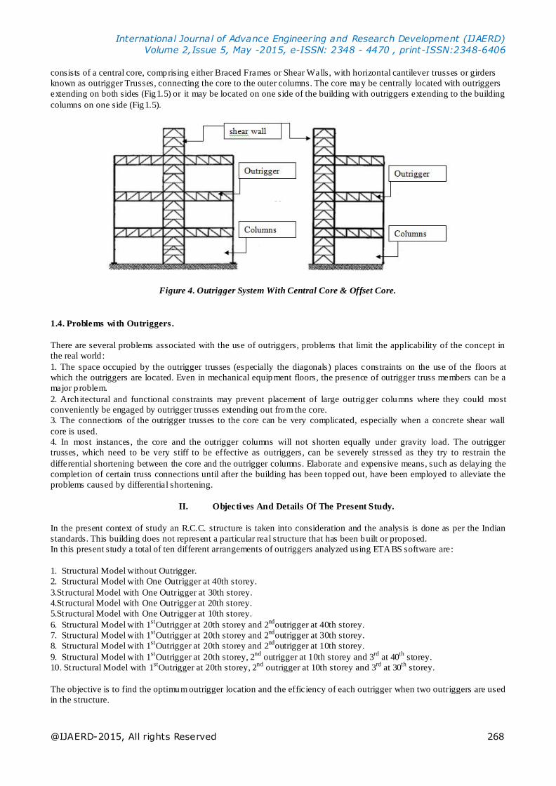
consists of a central core, comprising either Braced Frames or Shear Walls, with horizontal cantilever trusses or girders
known as outrigger Trusses, connecting the core to the outer columns. The core may be centrally located with outriggers
extending on both sides (Fig1.5) or it may be located on one side of the building with outriggers extending to the building
columns on one side (Fig1.5).
Figure 4. Outrigger System With Central Core & Offset Core.
1.4. Problems with Outriggers .
There are several problems associated with the use of outriggers, problems that limit the applicability of the concept in
the real world :
1. The space occupied by the outrigger trusses (especially the diagonals) places constraints on the use of the floors at
which the outriggers are located. Even in mechanical equipment floors, the presence of outrigger truss members can be a
major p roblem.
2. Arch itectural and functional constraints may prevent placement of large outrig ger columns where they could most
conveniently be engaged by outrigger trusses extending out from the core.
3. The connections of the outrigger trusses to the core can be very complicated, especially when a concrete shear wall
core is used.
4. In most instances, the core and the outrigger columns will not shorten equally under gravity load. The outrigger
trusses, which need to be very stiff to be effective as outriggers, can be severely stressed as they try to restrain the
differential shortening between the core and the outrigger columns. Elaborate and expensive means, such as delaying the
complet ion of certain truss connections until after the building has been topped out, have been employed to alleviate the
problems caused by differential shortening.
II. Objectives And Details Of The Present Study.
In the present context of study an R.C.C. structure is taken into consideration and the analysis is done as per the Indian
standards. This building does not represent a particular real structure that has been built or proposed.
In this present study a total of ten different arrangements of outriggers analyzed using ETABS software are:
1. Structural Model without Outrigger.
2. Structural Model with One Outrigger at 40th storey.
3.St ructural Model with One Outrigger at 30th storey.
4.St ructural Model with One Outrigger at 20th storey.
5.St ructural Model with One Outrigger at 10th storey.
6. Structural Model with 1st
Outrigger at 20th storey and 2nd
outrigger at 40th storey.
7. Structural Model with 1st
Outrigger at 20th storey and 2nd
outrigger at 30th storey.
8. Structural Model with 1st
Outrigger at 20th storey and 2nd
outrigger at 10th storey.
9. Structural Model with 1st
Outrigger at 20th storey, 2nd
outrigger at 10th storey and 3rd
at 40th
storey.
10. St ructural Model with 1st
Outrigger at 20th storey, 2nd
outrigger at 10th storey and 3rd
at 30th
storey.
The objective is to find the optimum outrigger location and the efficiency of each outrigger when two outriggers are used
in the structure.

International Journal of Advance Engineering and Research Development (IJAERD)
Volume 2,Issue 5, May -2015, e-ISSN: 2348 - 4470 , print-ISSN:2348-6406
@IJAERD-2015, All rights Reserved 269
III. ANALYS IS OF A 40 STOREY BUILDING
The model considered for this study is 150m h igh rise reinforced concrete building frame. The build ing represents a 40
storied office building. The Plan area of the Structure is 42m x 42m with columns spaced at 6m from center to center.
The height of each storey is 3m and all the floors are considered as Typical Floors. The location of the building is
assumed to be at Vadodara. An elevation and plan view of a typical structure is shown in fig.
Figure 5. Plan Of Typical Storey.
All wall piers are identical with a uniform wall thickness of 350mm over the entire height. The Bracing beams
(outriggers) and all other beams are 300mm wide and 600mm deep, Grade 50 concrete is considered (Compressive
strength 50 N/mm²) throughout the height of the building. And number of stories considered for all the cases are 40
stories, and roof height is considered as 150m. And storey to storey height is 3.0 m. And the outer and inner columns
sizes are considered as 750 x 750 mm and shear wall thickness is considered as 350 mm.
The method of analysis of the above mentioned system is based up on the assumptions that the outriggers are rigidly
attached to the core; The core is rig idly attached to the foundation; The sectional properties of the core, beams and
columns are uniform throughout the height; Tensional effects are not considered; Material behavior is in linear elastic
range; The Outrigger Beams are flexurally rig id and induce only axial forces in the columns; The lateral resistance is
provided only by the bending resistance of the core and the tie down action of the exterior columns connected to the
outrigger; The rotation of the core due to the shear deformation is negligib le.
Since the build ing is assumed to be a office build ing live load is cons idered as 3 kN/m². A floor load of 1kN/m² is
applied on all the slab panels on all the floors for the floor fin ishes and the other things. A member load as u.d.l. of 6
kN/m is considered on all beams for the wall load considering the wall to be made of Lig ht Weight Bricks. Wind load in
this study is established in accordance with IS 875(part 3-Wind loads).
Earthquake load in this study is established in accordance with IS 1893(part 1) -2002.The city of Hyderabad falls in “zone
3” (Z=0.16). The importance factor (I) of the building is taken as 1.0. The site is assumed to be medium site (Type II).
The response reduction factor R is taken as 5.0 for all frames. The fundamental time period (Ta) of all frames was
calculated as per clause 7.6.1 of the aforementioned code.
Ta = 0.075*h0.75

International Journal of Advance Engineering and Research Development (IJAERD)
Volume 2,Issue 5, May -2015, e-ISSN: 2348 - 4470 , print-ISSN:2348-6406
@IJAERD-2015, All rights Reserved 270
Based on the above data the ETABS calculates the design horizontal seismic coefficient (A h) using the Sa/g value from
the appropriate response spectrum. The Ah value calculated is utilized in calcu lating the design seismic base shear (VB)
as,
VB = Ah * W.
Where, W = seismic weight of the building.
The design seismic base shear so calculated is distributed along the height of the building as per the expression,
Qi = VB * (Wi*hi2)*(ΣWj*hj2)-1
Where, Qi = Design lateral force at floor i.
Wi= seismic weight of the floor i
hi= height of the floor I measured from base j = 1 to n,
n being no. of floors in the building at which masses are located.
The structure is analyzed as per the loading combinations provided in IS: 456-2000. The fo llowing load combinations are
used to determine the maximum lateral deflection in the structure.
i) DL+LL
ii) DL+LL±W L(x or y)
iii) DL+LL±EL(x or y)
iv) DL±W L(x or y)
v) DL±EL(x or y)
The structure with above mentioned specifications and assumptions is analyzed using the program ETABS and bending
moments, shear forces, lateral deflections are calculated for both Wind & Earthquake loading. Since the wind load ca ses
are governing, the graph and tables are represents the same. The structure with above mentioned specifications and
assumptions is analyzed using the program ETABS and bending moments, shear forces, lateral deflections are calculated
for both Wind & Earthquake loading. Since the wind load cases are governing, the graph and tables are represents the
same.
IV. RES ULTS & DISCUSSION
4.1. Displacement
Figure 5. Displacement Due to Earthquake &Wind(mm) (single outrigger).

International Journal of Advance Engineering and Research Development (IJAERD)
Volume 2,Issue 5, May -2015, e-ISSN: 2348 - 4470 , print-ISSN:2348-6406
@IJAERD-2015, All rights Reserved 271
Figure 6. Displacement Due to Earthquake &Wind(mm) (double outrigger).
Figure 7. Displacement Due to Earthquake &Wind(mm) (triple outrigger).
4.2. Shear force
Figure 8. Shear Force due to Earthquake &Wind(KN) (single outrigger).

International Journal of Advance Engineering and Research Development (IJAERD)
Volume 2,Issue 5, May -2015, e-ISSN: 2348 - 4470 , print-ISSN:2348-6406
@IJAERD-2015, All rights Reserved 272
Figure 9. Shear Force Due to Earthquake &Wind(KN) (double outrigger).
Figure 10.Shear Force Due to Earthquake & Wind(KN) (triple outrigger).
4.3. Bending Moment
Figure 11. Bending Moment Due to Earthquake &Wind(KNm) (single outrigger).

International Journal of Advance Engineering and Research Development (IJAERD)
Volume 2,Issue 5, May -2015, e-ISSN: 2348 - 4470 , print-ISSN:2348-6406
@IJAERD-2015, All rights Reserved 273
Figure 12.Bending Moment Due to Earthquake & Wind(KNm) (double outrigger).
Figure 13.Bending Moment Due to Earthquake & Wind(KNm) (triple outrigger).
4.4. Drift Index
Figure 14.Drift Index Due to Earthquake & Wind (single outrigger).

International Journal of Advance Engineering and Research Development (IJAERD)
Volume 2,Issue 5, May -2015, e-ISSN: 2348 - 4470 , print-ISSN:2348-6406
@IJAERD-2015, All rights Reserved 274
Figure 15.Drift Index Due to Earthquake & Wind (double outrigger).
Figure 16. Drift Index Due to Earthquake & Wind (triple outrigger).
V. CONCLUS ION
1. There is maximum displacement reduction when 1
st outrigger is placed at 20
th floor i.e. at mid height(Figure 5).
2. There is maximum shear fore reduction in core when 1st
outrigger is placed at 20th
floor i.e . at mid height (Figure 8).
3. If we consider overall height of build ing, there is maximum reduction in drift index when 1st
outrigger is placed at 20
th storey i.e. at mid height (Figure 14).
4. From above conclusion we consider 1st
outrigger location is at 20th
storey mid height.
5. There is maximum displacement reduction when 2nd
outrigger is placed at 10th
floor i.e. at 1/4th
height (Figure 6).
6. There is maximum shear fore reduction in core when 2nd
outrigger is placed at 20th
floor i.e. at m1/4th
height (Figure
9).
7. If we consider overall height of build ing, there is maximum reduction in drift index when 2nd
outrigger is placed at 10
th storey i.e. at 1/4
thheight (Figure 15).
8. From above 5, 6, 7 conclusion 2nd
outrigger is placed at 10th
floor i.e. at 1/4th
height.
9. There is maximum d isplacement reduction when 3rd
outrigger is placed at 30th
floor i.e. at 3/4th
height (Figure 7).
10. There is maximum shear fore reduction in core when 3rd
outrigger is placed at 30th
floor i.e. at 3/4th
height (Figure
10).
11. If we consider overall height of building, there is maximum reduction in drift index when 3rd
outrigger is placed at 30
th storey i.e. at 3/4
thheight (Figure 16).
12. From above9, 10, 11 conclusion we say 3rd
outrigger location is at 30th
storey 3/4th
height.

International Journal of Advance Engineering and Research Development (IJAERD)
Volume 2,Issue 5, May -2015, e-ISSN: 2348 - 4470 , print-ISSN:2348-6406
@IJAERD-2015, All rights Reserved 275
REFERENCES
[1] J. R. WU & Q. S. LI, “Structural performance of mult i-outrigger braced tall build ing”, Structural Design Tall Spec.
Build. Vol.12, 155–176, 2003.
[2] Shankar Nair, R ,“Belt Trusses and Basements as Virtual Outriggers for Tall Buildings ”, Engineering Journal ,
Fourth Quarter, Amercian journal of steel construction, 1998.
[3] Z. Bayati , . Mahdikhani and A.Rahaei ,“Optimized use of Multi-outrigger System to Stiffen Tall Buildings”, The
14th World Conference on Earthquake Engineering October 12-17, 2008, Beijing, China.
[4] Gerasimidis S. , Efthymiou E. , Ban iotopoulos C. C., “Optimum outrigger location of high rise steel building for
wind loading”, EACW E 5 , 2009.
[5] S. Fawzia& T. Fatima ,“Deflection control in composite build ing by using belt truss and outrigger system”, world
AcademF56y of Science, Engineering & Technology, vol 4, 2010.
[6] KiranKamath, N. Dirga, Asha U. Rao,” A study on static & dynamic behaviour of outrigger structural system for tall
building”, Bonfring International Journal of Industrial Engineering & management science, vol 2, no. 4, 2012.
[7] Raj KiranNanduri, B.suresh, ItheshamHussain, “Optimum position of outrigger system for high rise reinforced
concrete building under wind and earthquake load”, American Journal of engineering Research, 2013.