optimized steel deck design - amazon web services steel... · of steel deck types, their commonly...
TRANSCRIPT
© 2014 New Millennium Building Systems, LLC All rights reserved.
Optimized Steel Deck Design
1 of 70
© 2014 New Millennium Building Systems, LLC All rights reserved.
Continuing Education Commitment
New Millennium Building Systems is a Registered Provider of professional development hours (PDHs), and American Institute of Architects Continuing Education System (AIA/CES) courses. Credit earned on completion of this program will be reported according to rules set forth by those organizations. Certificates of Completion for all attendees are available on request. This program is registered with the AIA/CES for continuing professional education. As such, it does not include content that may be deemed or construed to be an approval or endorsement by the AIA of any material of construction or any method or manner of handling, using, distributing, or dealing in any material or product. Questions related to specific materials, methods, and services will be addressed at the conclusion of this presentation. AIA Provider Number: 40107447 AIA Course Number: 2021
2 of 70
© 2014 New Millennium Building Systems, LLC All rights reserved.
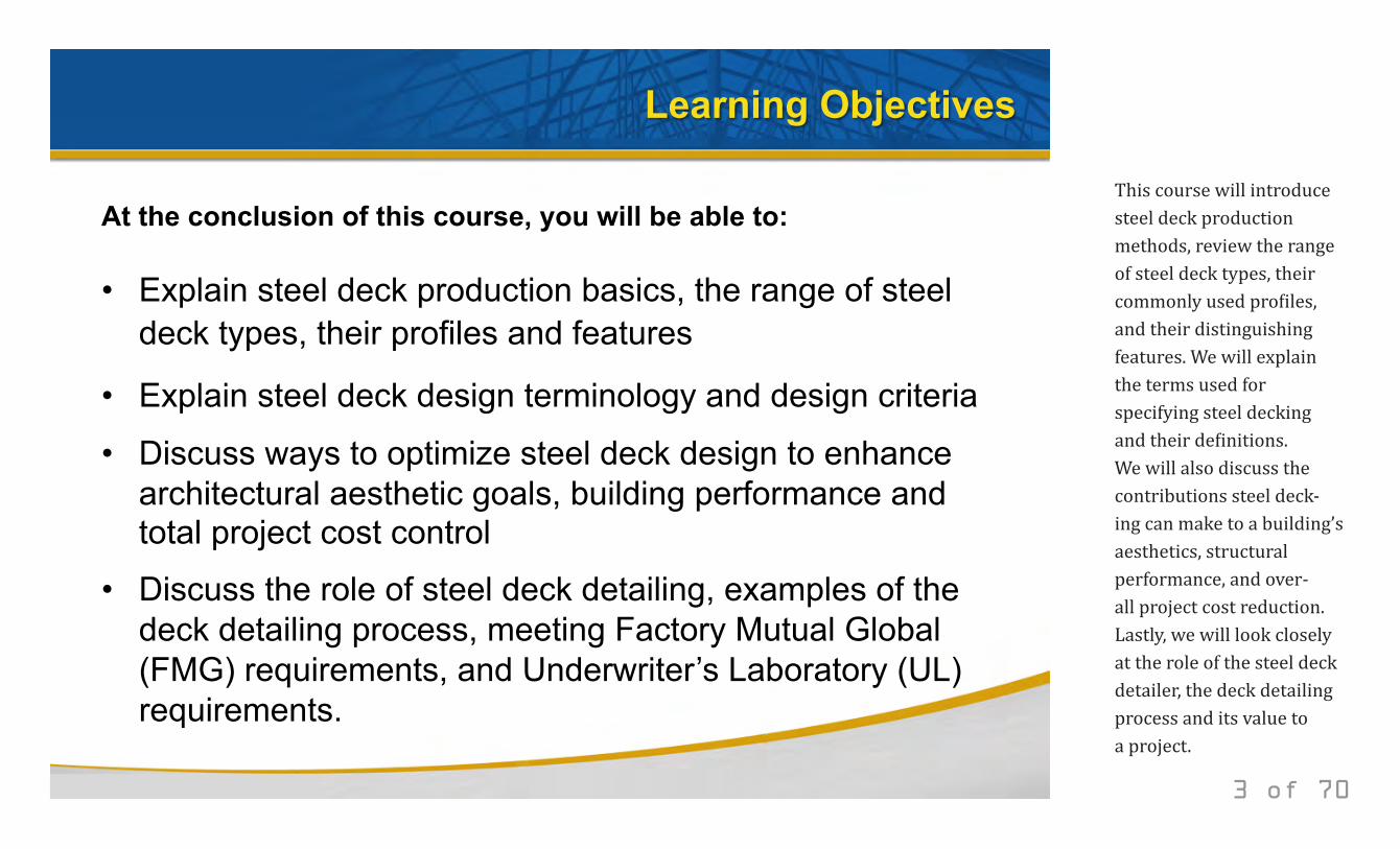
At the conclusion of this course, you will be able to: • Explain steel deck production basics, the range of steel
deck types, their profiles and features
• Explain steel deck design terminology and design criteria
• Discuss ways to optimize steel deck design to enhance architectural aesthetic goals, building performance and total project cost control
• Discuss the role of steel deck detailing, examples of the deck detailing process, meeting Factory Mutual Global (FMG) requirements, and Underwriter’s Laboratory (UL) requirements.
Learning Objectives
3 of 70
This course will introduce steel deck production methods, review the range of steel deck types, their commonly used profiles, and their distinguishing features. We will explain the terms used for specifying steel decking and their definitions. We will also discuss the contributions steel deck-ing can make to a building’s aesthetics, structural performance, and over-all project cost reduction. Lastly, we will look closely at the role of the steel deck detailer, the deck detailing process and its value to a project.
© 2014 New Millennium Building Systems, LLC All rights reserved.
Course Outline
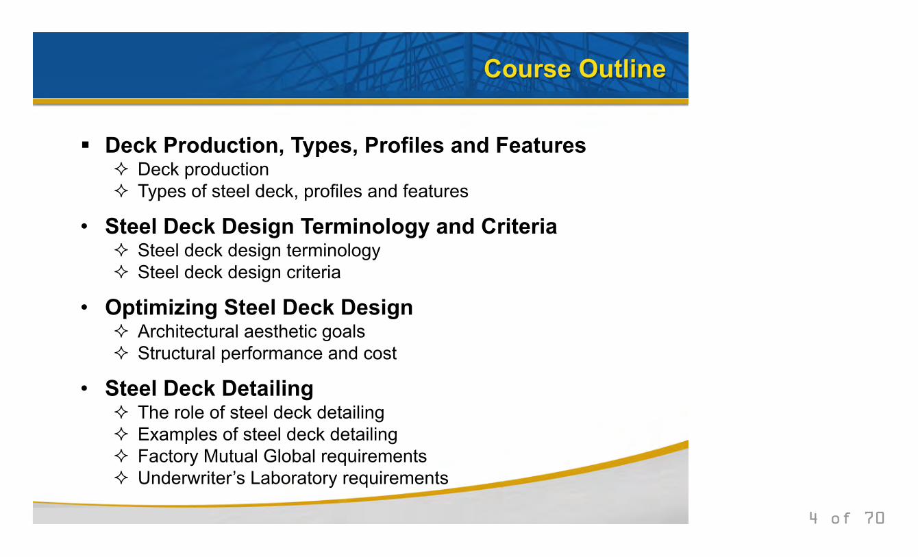
Deck Production, Types, Profiles and Features
Deck production Types of steel deck, profiles and features
• Steel Deck Design Terminology and Criteria Steel deck design terminology Steel deck design criteria
• Optimizing Steel Deck Design Architectural aesthetic goals Structural performance and cost
• Steel Deck Detailing The role of steel deck detailing Examples of steel deck detailing Factory Mutual Global requirements Underwriter’s Laboratory requirements
4 of 70
© 2014 New Millennium Building Systems, LLC All rights reserved.
Deck Production, Types, Profiles and Features
5 of 70
© 2014 New Millennium Building Systems, LLC All rights reserved.
Deck Production
6 of 70
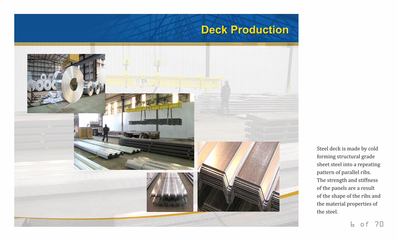
Steel deck is made by cold forming structural grade sheet steel into a repeating pattern of parallel ribs. The strength and stiffness of the panels are a result of the shape of the ribs and the material properties of the steel.
© 2014 New Millennium Building Systems, LLC All rights reserved.
Types of Steel Deck
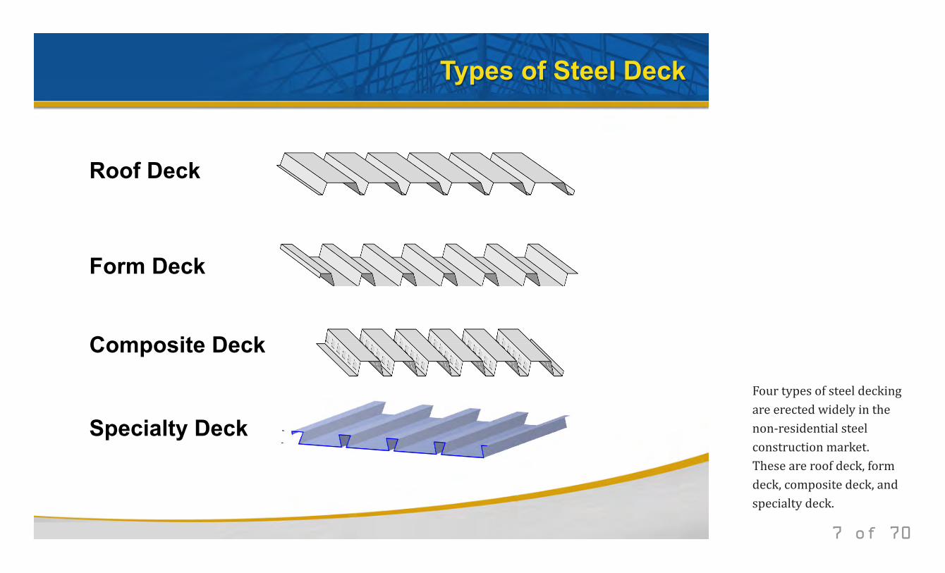
Roof Deck
Form Deck
Composite Deck
Specialty Deck
7 of 70
Four types of steel decking are erected widely in the non-residential steel construction market. These are roof deck, form deck, composite deck, and specialty deck.
© 2014 New Millennium Building Systems, LLC All rights reserved.
Roof Deck
8 of 70
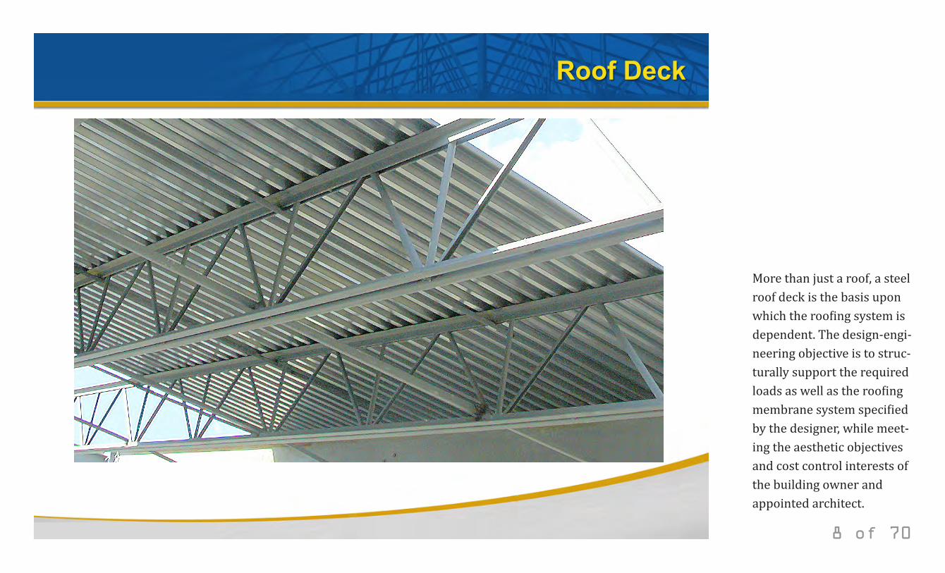
More than just a roof, a steel roof deck is the basis upon which the roofing system is dependent. The design-engi-neering objective is to struc-turally support the required loads as well as the roofing membrane system specified by the designer, while meet-ing the aesthetic objectives and cost control interests of the building owner and appointed architect.
© 2014 New Millennium Building Systems, LLC All rights reserved.
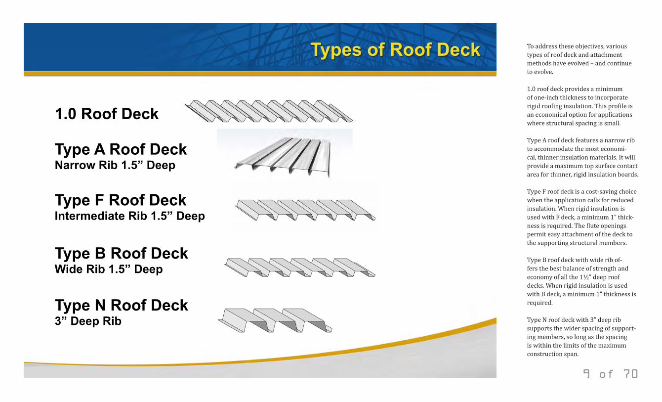
Types of Roof Deck
1.0 Roof Deck
Type A Roof Deck Narrow Rib 1.5” Deep
Type F Roof Deck Intermediate Rib 1.5” Deep
Type N Roof Deck 3” Deep Rib
Type B Roof Deck Wide Rib 1.5” Deep
9 of 70
To address these objectives, various types of roof deck and attachment methods have evolved – and continue to evolve. 1.0 roof deck provides a minimum of one-inch thickness to incorporate rigid roofing insulation. This profile is an economical option for applications where structural spacing is small. Type A roof deck features a narrow rib to accommodate the most economi-cal, thinner insulation materials. It will provide a maximum top surface contact area for thinner, rigid insulation boards. Type F roof deck is a cost-saving choice when the application calls for reduced insulation. When rigid insulation is used with F deck, a minimum 1” thick-ness is required. The flute openings permit easy attachment of the deck to the supporting structural members. Type B roof deck with wide rib of-fers the best balance of strength and economy of all the 1½” deep roof decks. When rigid insulation is used with B deck, a minimum 1” thickness is required. Type N roof deck with 3” deep rib supports the wider spacing of support-ing members, so long as the spacing is within the limits of the maximum construction span.
© 2014 New Millennium Building Systems, LLC All rights reserved.
Form Deck
10 of 70
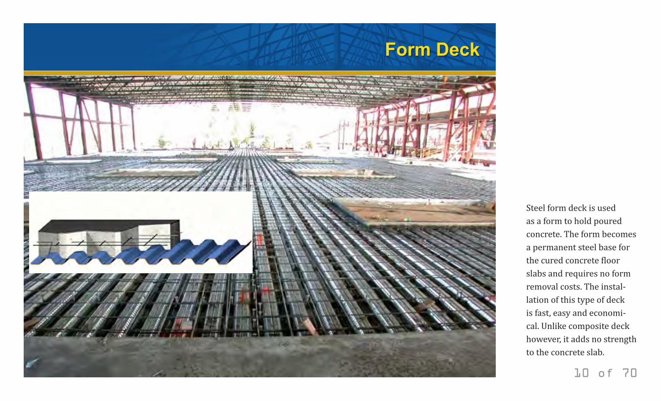
Steel form deck is used as a form to hold poured concrete. The form becomes a permanent steel base for the cured concrete floor slabs and requires no form removal costs. The instal-lation of this type of deck is fast, easy and economi-cal. Unlike composite deck however, it adds no strength to the concrete slab.
© 2014 New Millennium Building Systems, LLC All rights reserved.
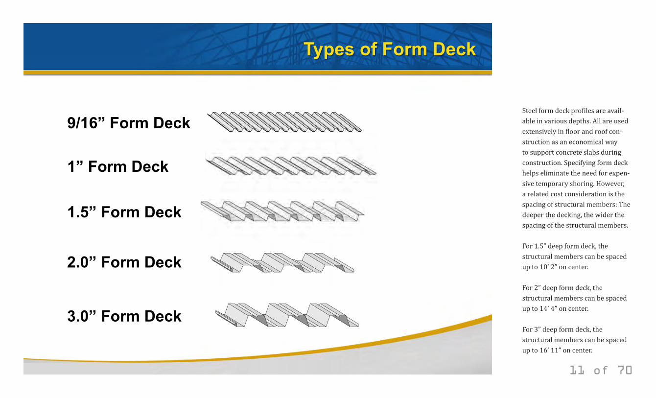
Types of Form Deck
9/16” Form Deck
1” Form Deck
1.5” Form Deck
2.0” Form Deck
3.0” Form Deck
11 of 70
Steel form deck profiles are avail-able in various depths. All are used extensively in floor and roof con-struction as an economical way to support concrete slabs during construction. Specifying form deck helps eliminate the need for expen-sive temporary shoring. However, a related cost consideration is the spacing of structural members: The deeper the decking, the wider the spacing of the structural members. For 1.5” deep form deck, the structural members can be spaced up to 10’ 2” on center.
For 2” deep form deck, the structural members can be spaced up to 14’ 4” on center.
For 3” deep form deck, the structural members can be spaced up to 16’ 11” on center.
© 2014 New Millennium Building Systems, LLC All rights reserved.
Composite Deck
12 of 70
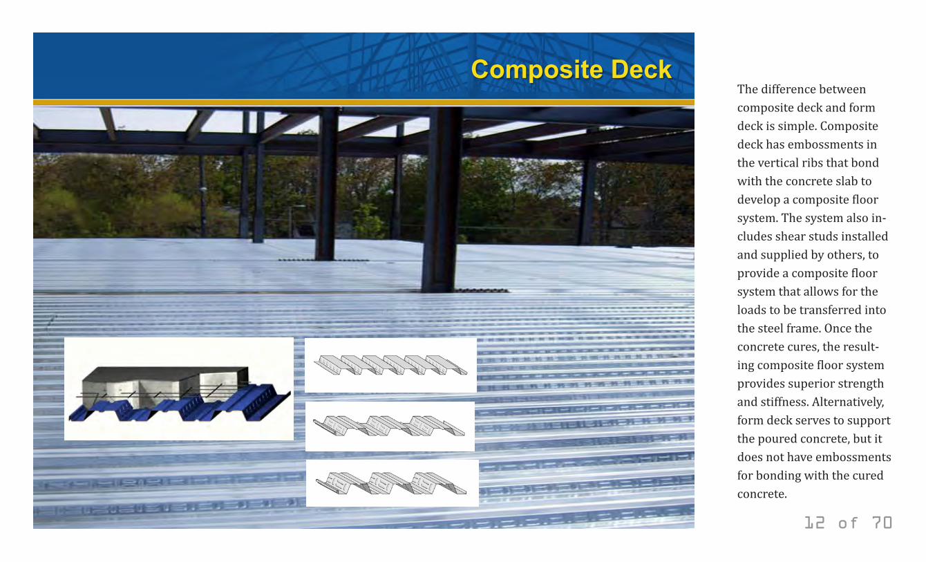
The difference between composite deck and form deck is simple. Composite deck has embossments in the vertical ribs that bond with the concrete slab to develop a composite floor system. The system also in-cludes shear studs installed and supplied by others, to provide a composite floor system that allows for the loads to be transferred into the steel frame. Once the concrete cures, the result-ing composite floor system provides superior strength and stiffness. Alternatively, form deck serves to support the poured concrete, but it does not have embossments for bonding with the cured concrete.
© 2014 New Millennium Building Systems, LLC All rights reserved.
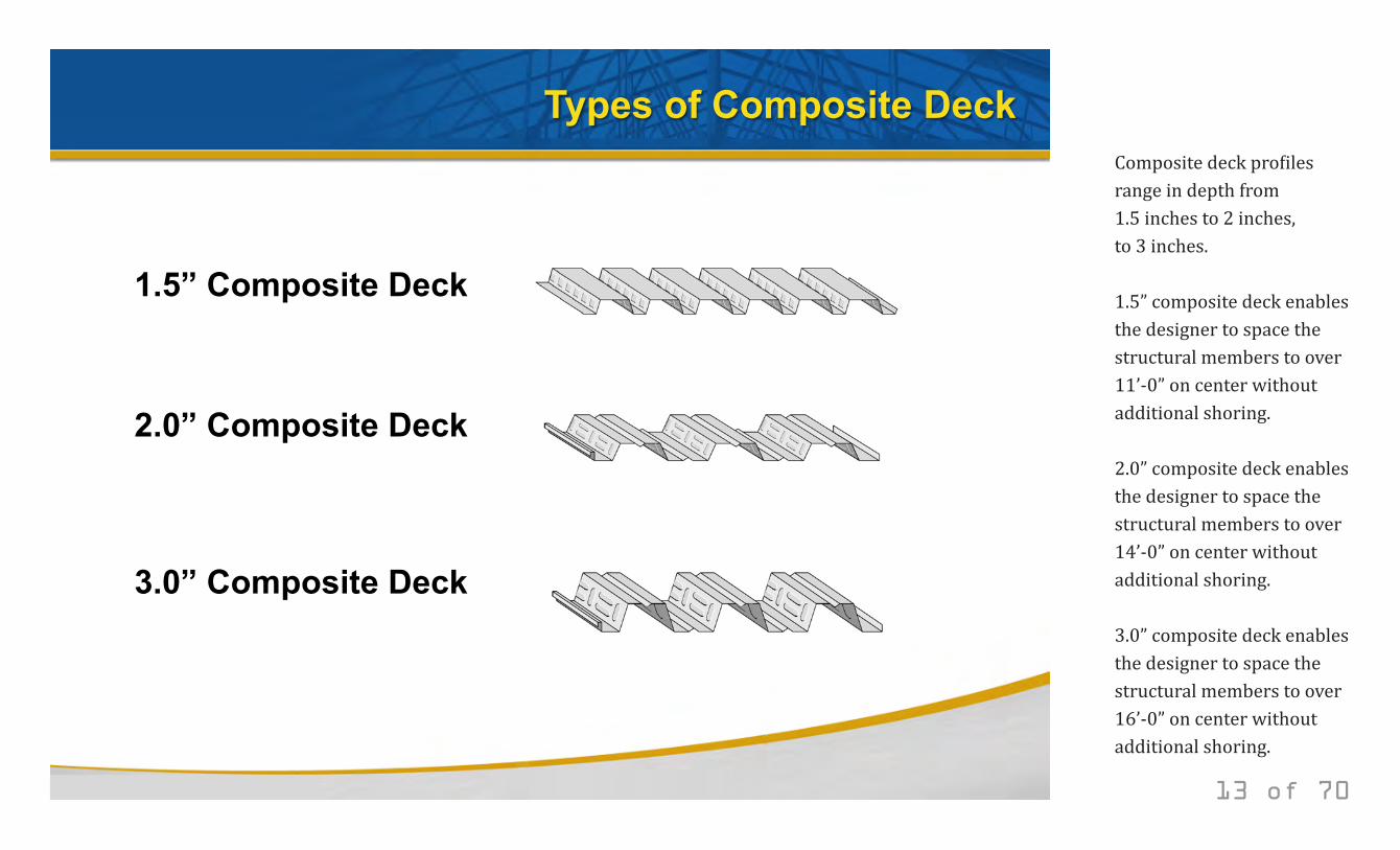
Types of Composite Deck
1.5” Composite Deck
2.0” Composite Deck
3.0” Composite Deck
13 of 70
Composite deck profiles range in depth from 1.5 inches to 2 inches, to 3 inches. 1.5” composite deck enables the designer to space the structural members to over 11’-0” on center without additional shoring. 2.0” composite deck enables the designer to space the structural members to over 14’-0” on center without additional shoring. 3.0” composite deck enables the designer to space the structural members to over 16’-0” on center without additional shoring.
© 2014 New Millennium Building Systems, LLC All rights reserved.
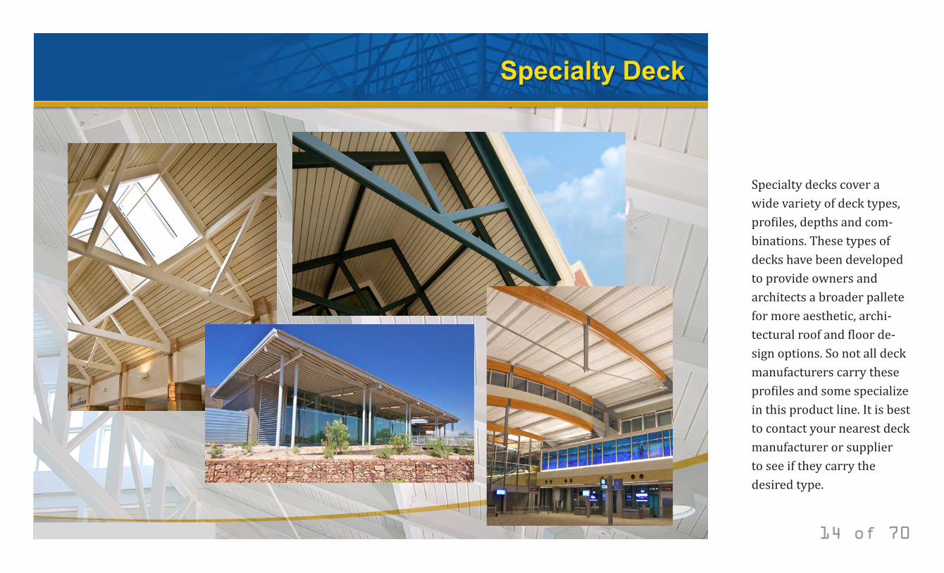
Specialty Deck
14 of 70
Specialty decks cover a wide variety of deck types, profiles, depths and com-binations. These types of decks have been developed to provide owners and architects a broader pallete for more aesthetic, archi-tectural roof and floor de-sign options. So not all deck manufacturers carry these profiles and some specialize in this product line. It is best to contact your nearest deck manufacturer or supplier to see if they carry the desired type.
© 2014 New Millennium Building Systems, LLC All rights reserved.
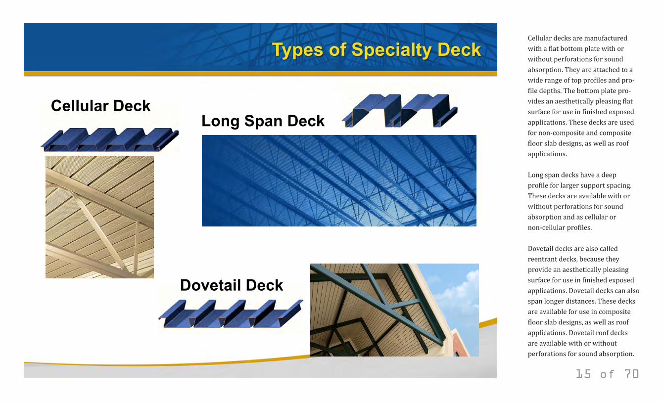
Types of Specialty Deck
Cellular Deck Long Span Deck
Dovetail Deck
15 of 70
Cellular decks are manufactured with a flat bottom plate with or without perforations for sound absorption. They are attached to a wide range of top profiles and pro-file depths. The bottom plate pro-vides an aesthetically pleasing flat surface for use in finished exposed applications. These decks are used for non-composite and composite floor slab designs, as well as roof applications. Long span decks have a deep profile for larger support spacing. These decks are available with or without perforations for sound absorption and as cellular or non-cellular profiles. Dovetail decks are also called reentrant decks, because they provide an aesthetically pleasing surface for use in finished exposed applications. Dovetail decks can also span longer distances. These decks are available for use in composite floor slab designs, as well as roof applications. Dovetail roof decks are available with or without perforations for sound absorption.
© 2014 New Millennium Building Systems, LLC All rights reserved.
Steel Deck Design Terminology and Criteria
16 of 70
© 2014 New Millennium Building Systems, LLC All rights reserved.
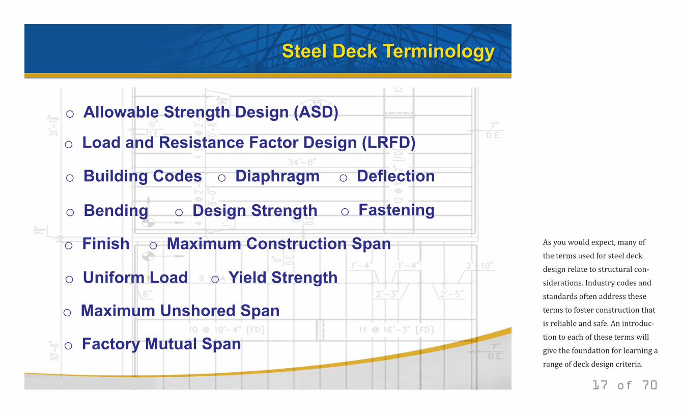
Steel Deck Terminology
o Allowable Strength Design (ASD)
o Load and Resistance Factor Design (LRFD)
o Building Codes o Diaphragm o Deflection
o Design Strength o Fastening
o Finish o Maximum Construction Span
o Uniform Load o Yield Strength
o Bending
o Maximum Unshored Span
o Factory Mutual Span
17 of 70
As you would expect, many of the terms used for steel deck design relate to structural con-siderations. Industry codes and standards often address these terms to foster construction that is reliable and safe. An introduc-tion to each of these terms will give the foundation for learning a range of deck design criteria.
© 2014 New Millennium Building Systems, LLC All rights reserved.
Terminology
Allowable Strength Design (ASD)
Load and Resistance Factor Design (LRFD)
18 of 70
There are two optional methods for factoring steel deck design. The tradi-tional Allowable Strength Design (ASD) method is based on using an allowable design strength, calculated by dividing the component nominal strength by a safety factor. Alternatively, the Load and Resistance Factor Design (LRFD) method is based on the combined fac-toring of applied loads up as a function of loading predictability and factoring the component resistance (nominal strength) down as a function of reli-ability and importance. While these are similar methods, they are not the same. ASD uses a constant factor of safety for all designs, no matter what the load type, while LRFD requires a higher fac-tor of safety for loads with higher vari-ability (less predictability). The LRFD method requires the use of higher load factors for loads with higher variance, such as live or snow loads. For more information on the distinction between ASD and LRFD structural steel design, see the AISC Steel Construction Manual available on the AISC web site.
© 2014 New Millennium Building Systems, LLC All rights reserved.
Terminology
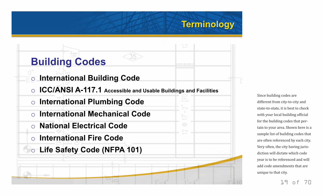
o International Building Code o ICC/ANSI A-117.1 Accessible and Usable Buildings and Facilities
o International Plumbing Code o International Mechanical Code o National Electrical Code o International Fire Code o Life Safety Code (NFPA 101)
Building Codes
19 of 70
Since building codes are different from city-to-city and state-to-state, it is best to check with your local building official for the building codes that per-tain to your area. Shown here is a sample list of building codes that are often referenced by each city. Very often, the city having juris-diction will dictate which code year is to be referenced and will add code amendments that are unique to that city.
© 2014 New Millennium Building Systems, LLC All rights reserved.
Terminology
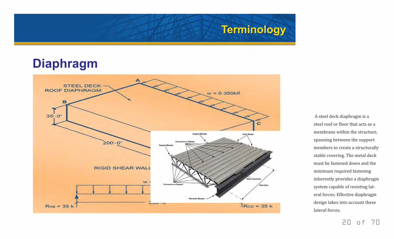
Diaphragm
20 of 70
A steel deck diaphragm is a steel roof or floor that acts as a membrane within the structure, spanning between the support members to create a structurally stable covering. The metal deck must be fastened down and the minimum required fastening inherently provides a diaphragm system capable of resisting lat-eral forces. Effective diaphragm design takes into account these lateral forces.
© 2014 New Millennium Building Systems, LLC All rights reserved.
Terminology
Deflection
21 of 70
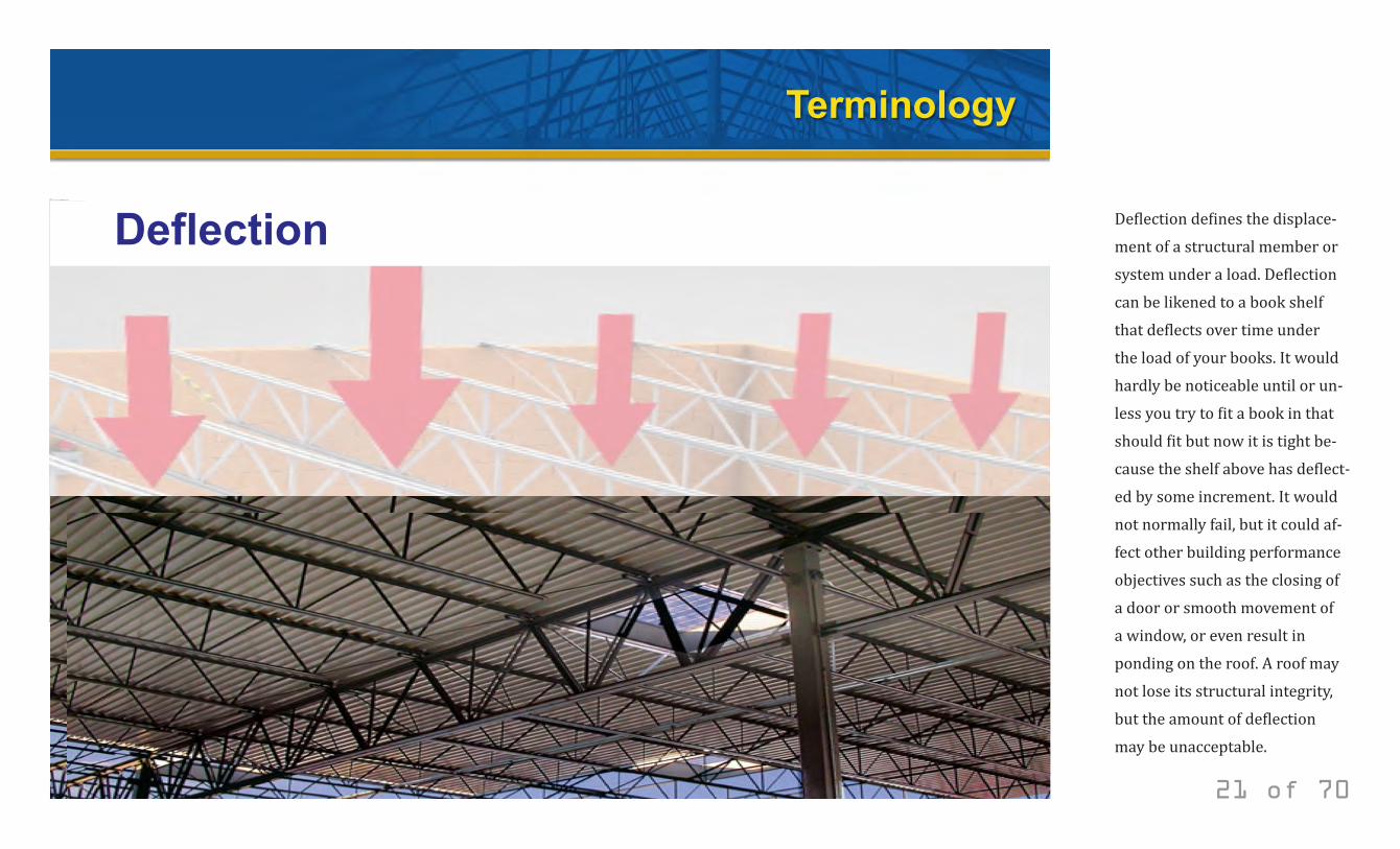
Deflection defines the displace-ment of a structural member or system under a load. Deflection can be likened to a book shelf that deflects over time under the load of your books. It would hardly be noticeable until or un-less you try to fit a book in that should fit but now it is tight be-cause the shelf above has deflect-ed by some increment. It would not normally fail, but it could af-fect other building performance objectives such as the closing of a door or smooth movement of a window, or even result in ponding on the roof. A roof may not lose its structural integrity, but the amount of deflection may be unacceptable.

© 2014 New Millennium Building Systems, LLC All rights reserved.
Terminology
Bending
22 of 70
Bending, also called bending moment, is M=wl2/8 for simple and two span conditions; or M=wl2/10 for three span conditions. Bending is different than deflection. The moment calculation or limit state relates to when the deck twists or bends to the point that the flutes buckle and thereby the deck loses it’s structural properties and is unable to return to its original shape without some external mechanical means. This would constitute a failure, even though it may be without breakage. Another limit state called “shear” would take the situation beyond failure to breakage.
© 2014 New Millennium Building Systems, LLC All rights reserved.
Terminology
Design Strength
23 of 70
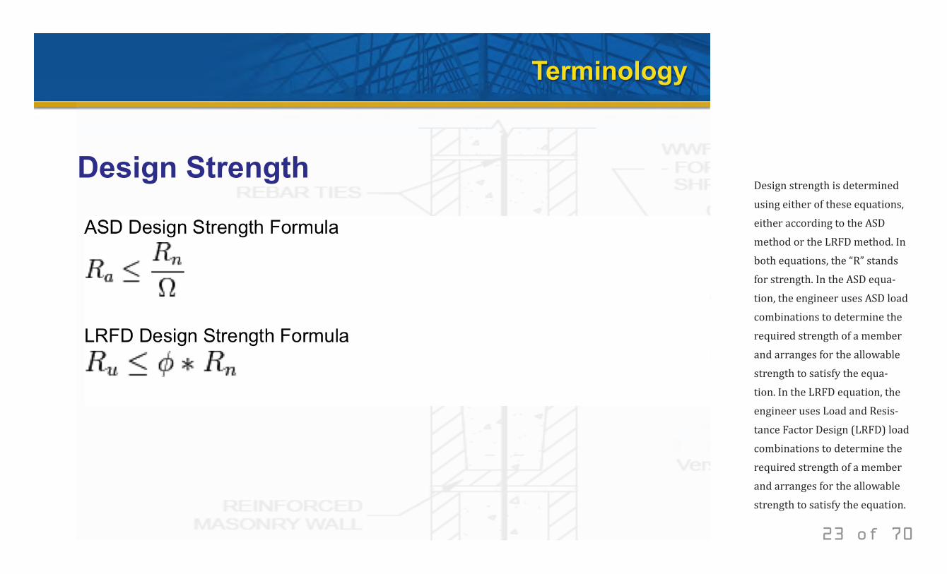
Design strength is determined using either of these equations, either according to the ASD method or the LRFD method. In both equations, the “R” stands for strength. In the ASD equa-tion, the engineer uses ASD load combinations to determine the required strength of a member and arranges for the allowable strength to satisfy the equa-tion. In the LRFD equation, the engineer uses Load and Resis-tance Factor Design (LRFD) load combinations to determine the required strength of a member and arranges for the allowable strength to satisfy the equation.
© 2014 New Millennium Building Systems, LLC All rights reserved.
Terminology
Fastening
Mechanical Fastening Sidelap Fastening
Fastening Layout
24 of 70
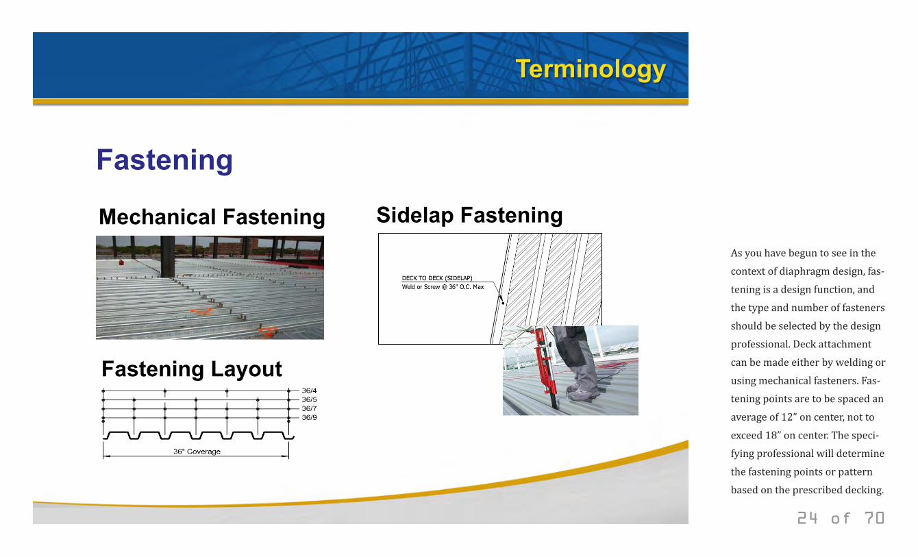
As you have begun to see in the context of diaphragm design, fas-tening is a design function, and the type and number of fasteners should be selected by the design professional. Deck attachment can be made either by welding or using mechanical fasteners. Fas-tening points are to be spaced an average of 12” on center, not to exceed 18” on center. The speci-fying professional will determine the fastening points or pattern based on the prescribed decking.
© 2014 New Millennium Building Systems, LLC All rights reserved.
Terminology
Fastening
Weld Washers
Puddle Welding
Button Punching
25 of 70
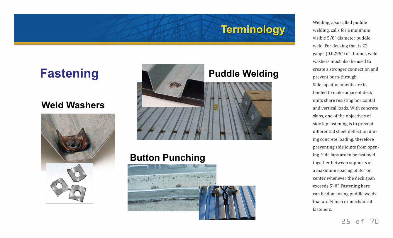
Welding, also called puddle welding, calls for a minimum visible 5/8” diameter puddle weld. For decking that is 22 gauge (0.0295”) or thinner, weld washers must also be used to create a stronger connection and prevent burn-through.Side lap attachments are in-tended to make adjacent deck units share resisting horizontal and vertical loads. With concrete slabs, one of the objectives of side lap fastening is to prevent differential sheet deflection dur-ing concrete loading, therefore preventing side joints from open-ing. Side laps are to be fastened together between supports at a maximum spacing of 36” on center whenever the deck span exceeds 5’-0”. Fastening here can be done using puddle welds that are ¾ inch or mechanical fasteners.
© 2014 New Millennium Building Systems, LLC All rights reserved.
Terminology
Finish
Galvanized Deck Painted Deck
Prime Painted Deck
26 of 70
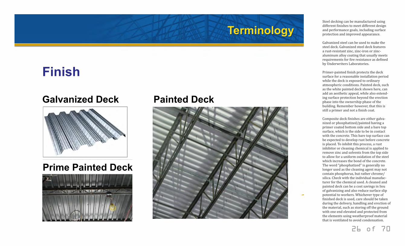
Steel decking can be manufactured using different finishes to meet different design and performance goals, including surface protection and improved appearance.
Galvanized steel can be used to make the steel deck. Galvanized steel deck features a rust-resistant zinc, zinc-iron or zinc-aluminum alloy coating that usually meets requirements for fire resistance as defined by Underwriters Laboratories.
Primer-painted finish protects the deck surface for a reasonable installation period while the deck is exposed to ordinary atmospheric conditions. Painted deck, such as the white painted deck shown here, can add an aesthetic appeal, while also extend-ing surface protection beyond the erection phase into the ownership phase of the building. Remember however, that this is still a primer and not a finish coat.
Composite deck finishes are either galva-nized or phosphatized/painted having a primer coated bottom side and a bare top surface, which is the side to be in contact with the concrete. This bare top surface can be expected to develop rust before concrete is placed. To inhibit this process, a rust inhibitor or cleaning chemical is applied to remove zinc and solvents from the top side to allow for a uniform oxidation of the steel which increases the bond of the concrete. The word “phosphatized” is generally no longer used as the cleaning agent may not contain phosphorus, but rather chrome/silica. Check with the individual manufac-turer for the chemical used. A cleaned and painted deck can be a cost savings in lieu of galvanizing and also reduce surface slip potential to workers. Whichever type of finished deck is used, care should be taken during the delivery, handling and erection of the material, such as storing off the ground with one end elevated and protected from the elements using weatherproof material that is ventilated to avoid condensation.
© 2014 New Millennium Building Systems, LLC All rights reserved.
Terminology
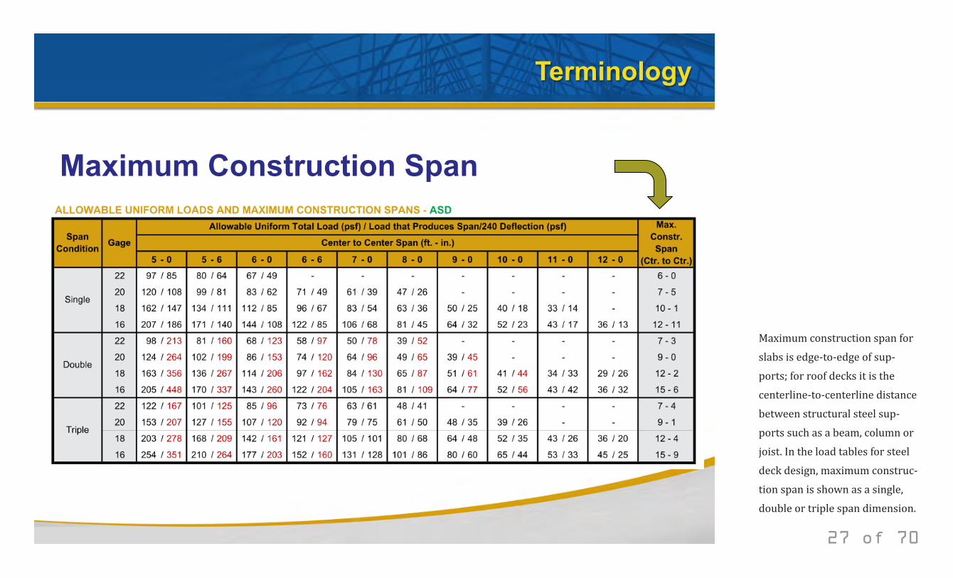
Maximum Construction Span
27 of 70
Maximum construction span for slabs is edge-to-edge of sup-ports; for roof decks it is the centerline-to-centerline distance between structural steel sup-ports such as a beam, column or joist. In the load tables for steel deck design, maximum construc-tion span is shown as a single, double or triple span dimension.
© 2014 New Millennium Building Systems, LLC All rights reserved.
Terminology
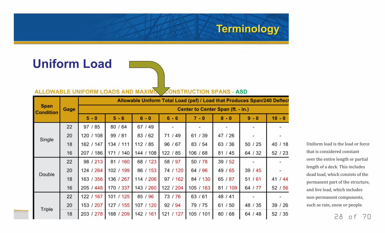
Uniform Load
28 of 70
Uniform load is the load or force that is considered constant over the entire length or partial length of a deck. This includes dead load, which consists of the permanent part of the structure, and live load, which includes non-permanent components, such as rain, snow or people.
© 2014 New Millennium Building Systems, LLC All rights reserved.
Terminology
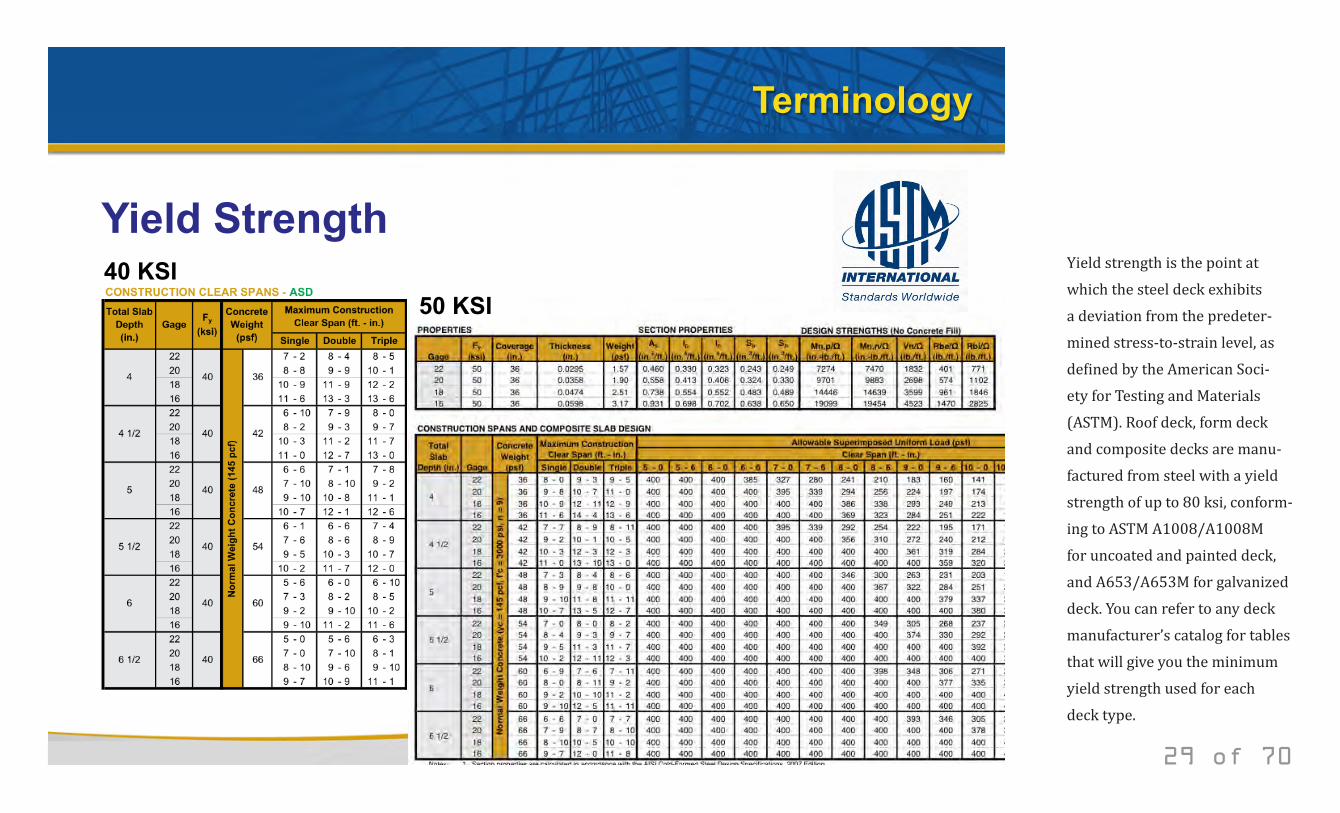
Yield Strength 40 KSI
50 KSI
29 of 70
Yield strength is the point at which the steel deck exhibits a deviation from the predeter-mined stress-to-strain level, as defined by the American Soci-ety for Testing and Materials (ASTM). Roof deck, form deck and composite decks are manu-factured from steel with a yield strength of up to 80 ksi, conform-ing to ASTM A1008/A1008M for uncoated and painted deck, and A653/A653M for galvanized deck. You can refer to any deck manufacturer’s catalog for tables that will give you the minimum yield strength used for each deck type.
© 2014 New Millennium Building Systems, LLC All rights reserved.
Terminology
Maximum Un-shored Span
30 of 70
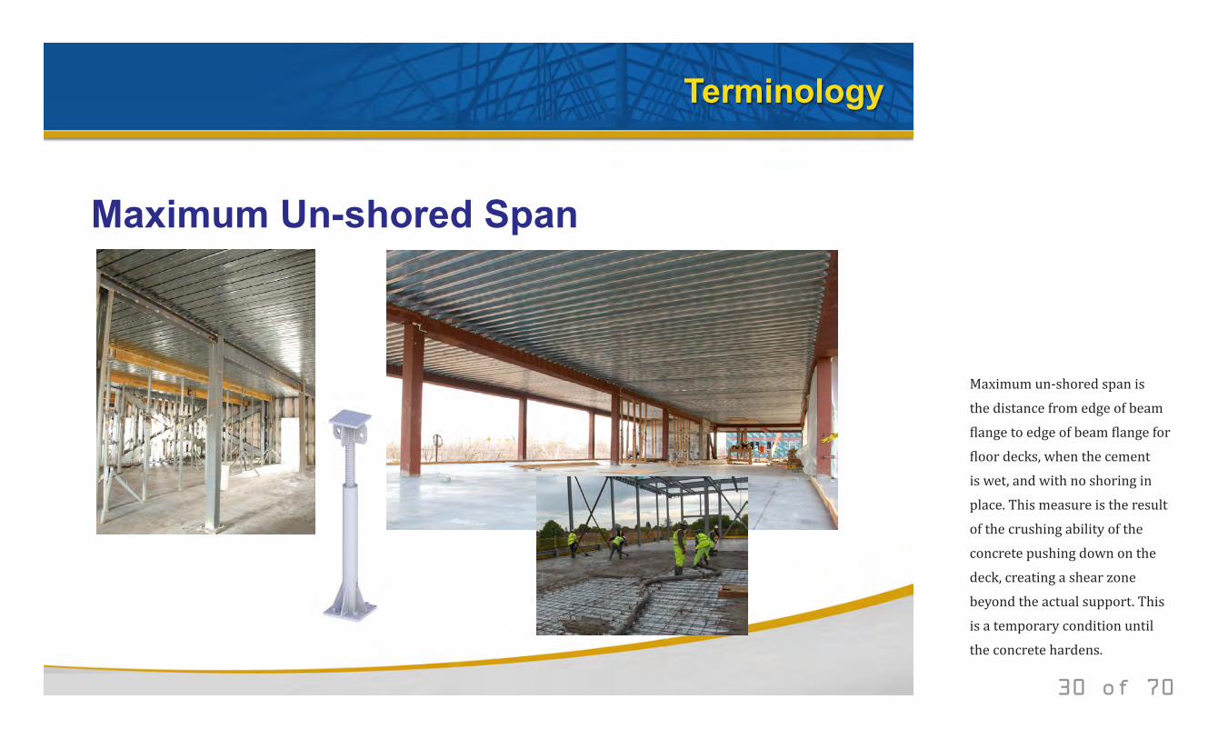
Maximum un-shored span is the distance from edge of beam flange to edge of beam flange for floor decks, when the cement is wet, and with no shoring in place. This measure is the result of the crushing ability of the concrete pushing down on the deck, creating a shear zone beyond the actual support. This is a temporary condition until the concrete hardens.
© 2014 New Millennium Building Systems, LLC All rights reserved.
Terminology
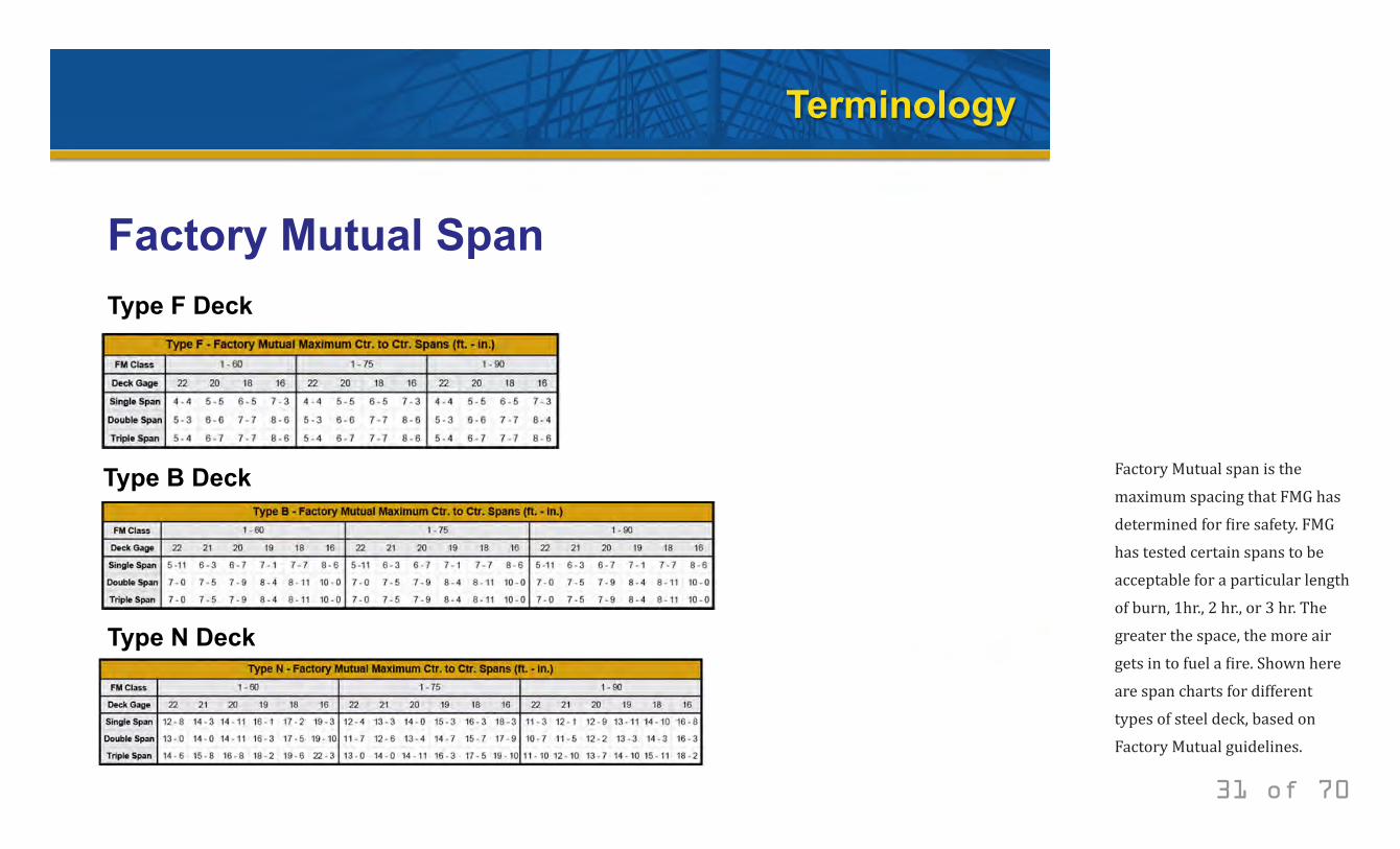
Factory Mutual Span Type F Deck
Type B Deck
Type N Deck
31 of 70
Factory Mutual span is the maximum spacing that FMG has determined for fire safety. FMG has tested certain spans to be acceptable for a particular length of burn, 1hr., 2 hr., or 3 hr. The greater the space, the more air gets in to fuel a fire. Shown here are span charts for different types of steel deck, based on Factory Mutual guidelines.
© 2014 New Millennium Building Systems, LLC All rights reserved.
Steel Deck Design Criteria
• Roof Deck • Form Deck • Composite Deck • Specialty Deck
32 of 70
The criteria for steel deck design often relates to the type of decking being used.
© 2014 New Millennium Building Systems, LLC All rights reserved.
Steel Deck Design Criteria
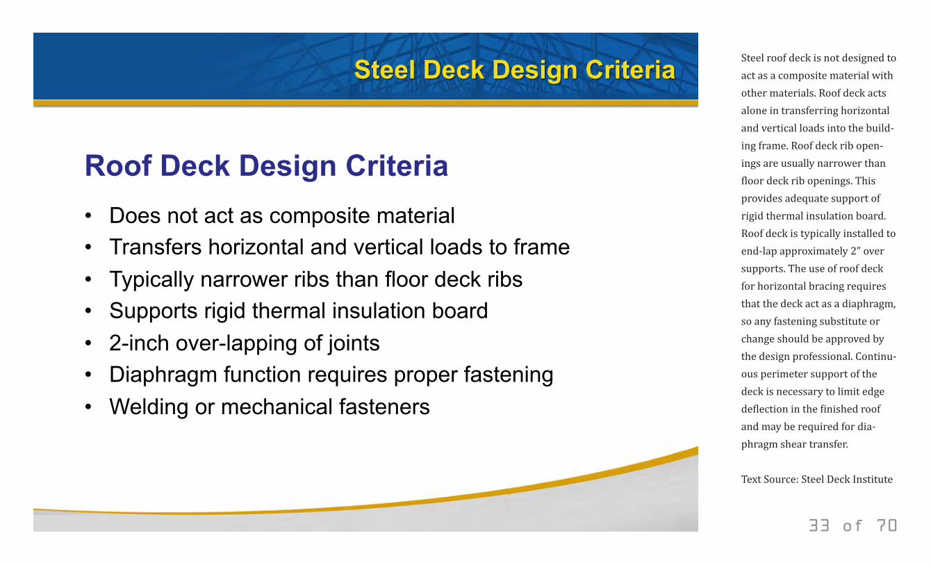
Roof Deck Design Criteria • Does not act as composite material • Transfers horizontal and vertical loads to frame • Typically narrower ribs than floor deck ribs • Supports rigid thermal insulation board • 2-inch over-lapping of joints • Diaphragm function requires proper fastening • Welding or mechanical fasteners
33 of 70
Steel roof deck is not designed to act as a composite material with other materials. Roof deck acts alone in transferring horizontal and vertical loads into the build-ing frame. Roof deck rib open-ings are usually narrower than floor deck rib openings. This provides adequate support of rigid thermal insulation board. Roof deck is typically installed to end-lap approximately 2” over supports. The use of roof deck for horizontal bracing requires that the deck act as a diaphragm, so any fastening substitute or change should be approved by the design professional. Continu-ous perimeter support of the deck is necessary to limit edge deflection in the finished roof and may be required for dia-phragm shear transfer.
Text Source: Steel Deck Institute
© 2014 New Millennium Building Systems, LLC All rights reserved.
Steel Deck Design Criteria
Form Deck Design Criteria • Used as a concrete form for floors and roofs
• Welding or mechanical fasteners
• Use weld washers for 22 gauge and thinner
• Galvanized required for roofs using concrete fill
• Patented dry-installed systems for primary roof
load-carrying
34 of 70
Steel form deck can be any floor or roof deck product used as a concrete form. Connections to the frame are by the same methods used to attach floor or roof deck. Welding washers are recom-mended when welding metal thickness is less than 0.0280 inches. Galvanized G90 deck must be used for those roof deck systems where form deck is used to carry a lightweight insulating concrete fill. In a patented, dry in-stalled roof deck assembly, form deck is utilized as the primary load-carrying element. This assembly functions as a structural roof deck diaphragm. The assembly may include dry installed thermal insulation placed above either prime painted, field painted galvanized or galvanized and painted steel sections.
In order to hasten the drying time of concrete that is cast on it, some decks can be supplied with elongated perfora-tions (vents) in their bottom flutes. This facilitates the draining of excess mix water (added to allow for pumping and placement of the mix) from the cemen-tious slurry component of lightweight insulating concrete systems (LWIC) of floors or roofs. In addition, the venting allows for the reduction of vapor pres-sure that will develop in the LWIC when covered with an impermeable roofing membrane.
Text Source: Steel Deck Institute
© 2014 New Millennium Building Systems, LLC All rights reserved.
Steel Deck Design Criteria
Composite Deck Design Criteria
• Functions as working platform once installed
• Stabilizes the building frame
• Serves as forms for the concrete
• Shear devices lock together with the concrete
• Devices mechanically reinforce the concrete
35 of 70
Steel composite deck, after installation and adequate fasten-ing, serves several purposes. It acts as a working platform, sta-bilizes the building frame, serves as concrete form for the slab and reinforces the slab to carry the design loads applied during the life of the building. Composite decks are distinguished by the presence of shear connector de-vices as part of the deck. These devices are designed to mechani-cally lock the concrete and deck together so that the concrete and the deck work together to carry subsequent floor loads. The shear connector devices can be manufactured into the decking as rolled-in embossments, lugs, holes or wires welded to the panels. The deck profile configu-ration can also be used to inter-lock concrete and steel. Text Source: Steel Deck Institute
© 2014 New Millennium Building Systems, LLC All rights reserved.
Steel Deck Design Criteria
Specialty Deck Design Criteria
• Dovetail Deck
• Long Span Deck
• Cellular Deck
• Electrified Deck
• Acoustical Deck
• Stainless Steel Deck
36 of 70
In response to market needs and wants, steel decking formats continue to devel-op, often flowing from preceding deck designs. Dovetail deck, long span deck, and cellular deck are ideas inspired by roof, form and composite decking. For example, cellular deck borrows from the composite deck design approach to add sound dampening and a smooth, flat underside appearance.
Similarly, electrified decking took the cellular deck concept and integrated wire-ways, data units and other voice-data-video elements to answer the growing need for more integrated structured cabling in building design. These methods of deck design and con-struction bring a new range of function-ality and architectural aesthetics.
Acoustical deck focuses on the sound-dampening objective. Acoustical deck is manufactured to have perforated holes in the vertical ribs. Once the deck is installed, insulation batts supplied by the deck manufacturer are placed in the ribs. This achieves the “Noise Reduction Coefficient” or NRC rating planned by the architect and structural engineer of record for the design of the space. Stainless steel deck addresses the need for corrosion resistance. Decking made of stainless steel is resistant to salts, acids and alkaline solutions, especially in applications having elevated temperatures and pressures. Frequently, long-term deck mainte-nance cost reduction is a criteria for specifying stainless steel decking.
© 2014 New Millennium Building Systems, LLC All rights reserved.
Optimizing Steel Deck Design
37 of 70
© 2014 New Millennium Building Systems, LLC All rights reserved.
Optimizing Steel Deck Design
• Architectural Aesthetics • Structural Performance and Cost
38 of 70
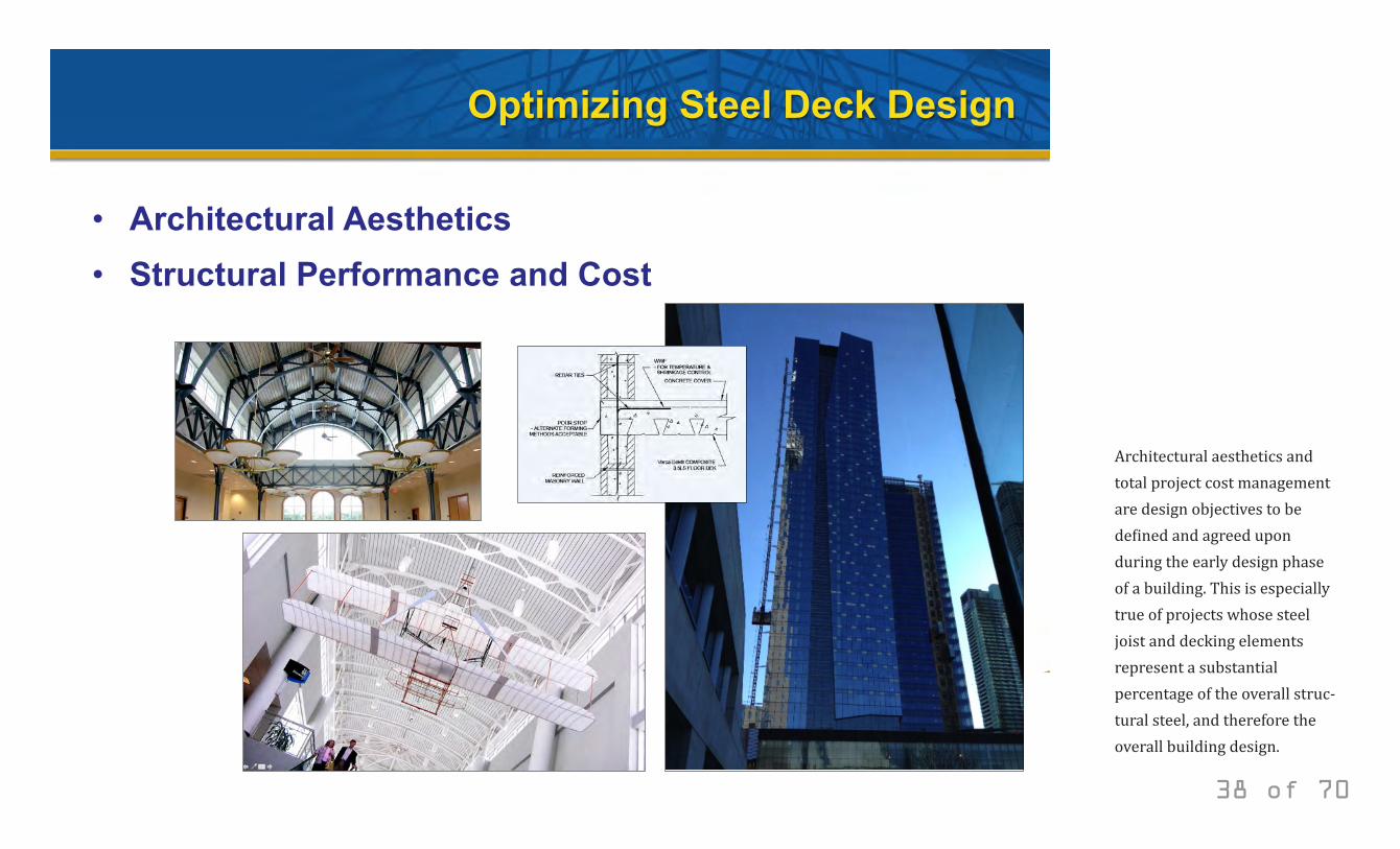
Architectural aesthetics and total project cost management are design objectives to be defined and agreed upon during the early design phase of a building. This is especially true of projects whose steel joist and decking elements represent a substantial percentage of the overall struc-tural steel, and therefore the overall building design.
© 2014 New Millennium Building Systems, LLC All rights reserved.
Optimizing Steel Deck Design
Architectural Aesthetics
39 of 70
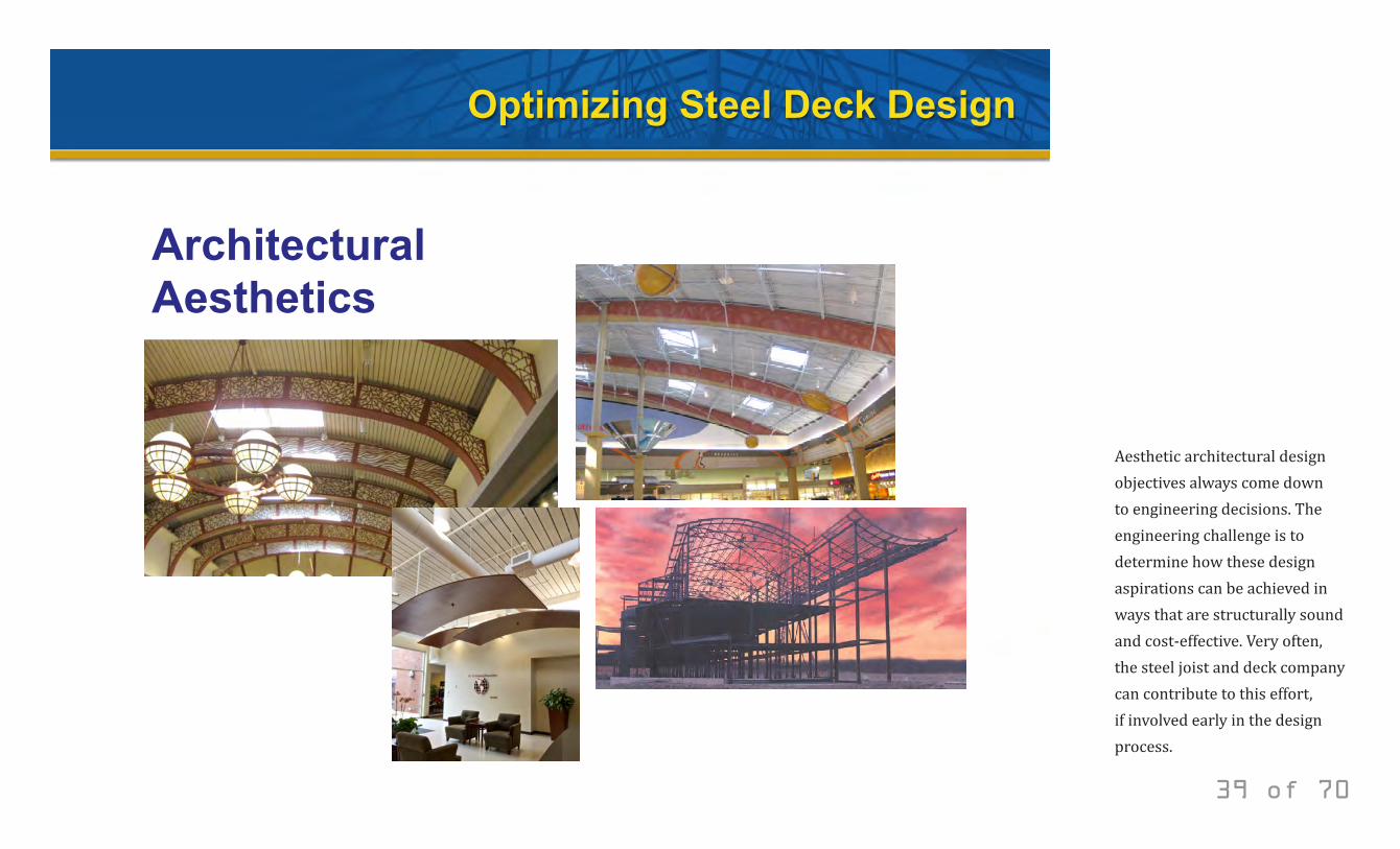
Aesthetic architectural design objectives always come down to engineering decisions. The engineering challenge is to determine how these design aspirations can be achieved in ways that are structurally sound and cost-effective. Very often, the steel joist and deck company can contribute to this effort, if involved early in the design process.
© 2014 New Millennium Building Systems, LLC All rights reserved.
Optimizing Steel Deck Design
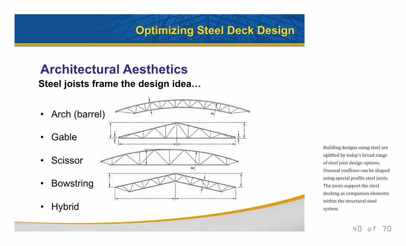
Architectural Aesthetics Steel joists frame the design idea…
• Arch (barrel)
• Gable
• Scissor
• Bowstring
• Hybrid
40 of 70
Building designs using steel are uplifted by today’s broad range of steel joist design options. Unusual rooflines can be shaped using special profile steel joists. The joists support the steel decking as companion elements within the structural steel system.
© 2014 New Millennium Building Systems, LLC All rights reserved.
Optimizing Steel Deck Design
Architectural Aesthetics
41 of 70
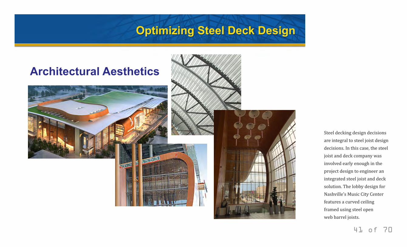
Steel decking design decisions are integral to steel joist design decisions. In this case, the steel joist and deck company was involved early enough in the project design to engineer an integrated steel joist and deck solution. The lobby design for Nashville’s Music City Center features a curved ceiling framed using steel open web barrel joists.
© 2014 New Millennium Building Systems, LLC All rights reserved.
Optimizing Steel Deck Design
Structural Performance and Cost
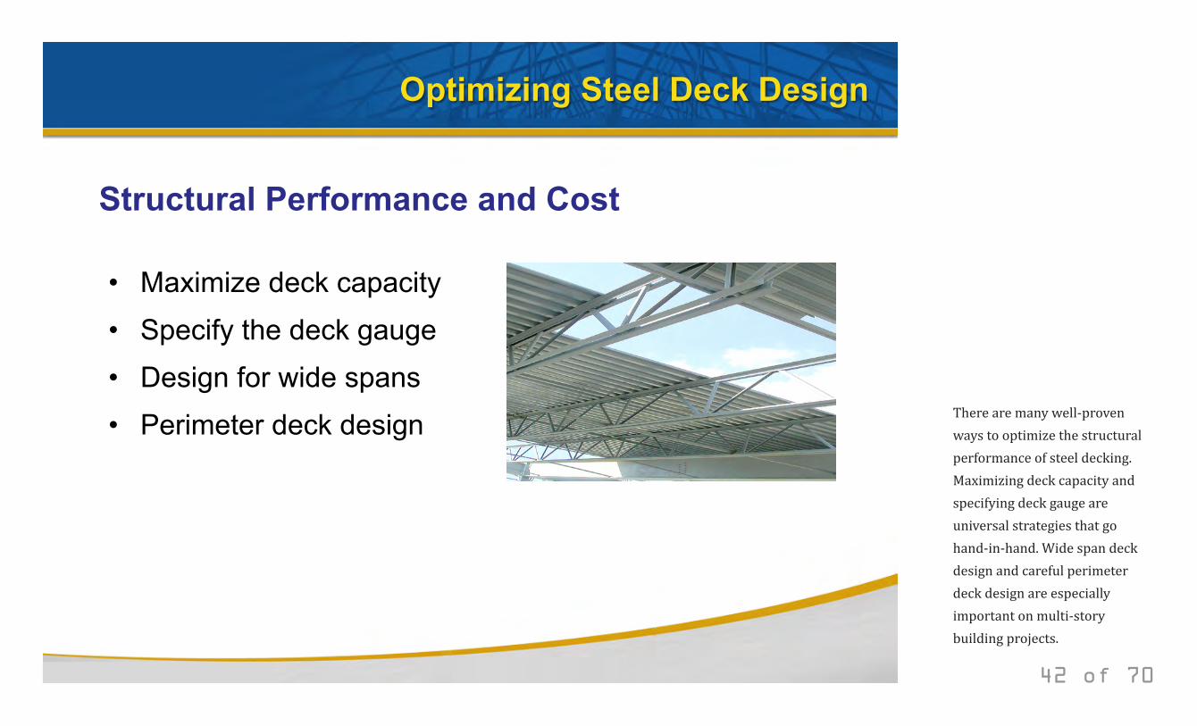
• Maximize deck capacity
• Specify the deck gauge
• Design for wide spans
• Perimeter deck design
42 of 70
There are many well-proven ways to optimize the structural performance of steel decking. Maximizing deck capacity and specifying deck gauge are universal strategies that go hand-in-hand. Wide span deck design and careful perimeter deck design are especially important on multi-story building projects.
© 2014 New Millennium Building Systems, LLC All rights reserved.
Optimizing Steel Deck Design
Structural Performance and Cost Maximize deck capacity
43 of 70
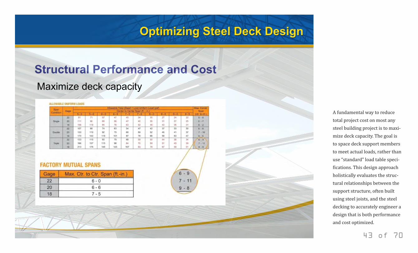
A fundamental way to reduce total project cost on most any steel building project is to maxi-mize deck capacity. The goal is to space deck support members to meet actual loads, rather than use “standard” load table speci-fications. This design approach holistically evaluates the struc-tural relationships between the support structure, often built using steel joists, and the steel decking to accurately engineer a design that is both performance and cost optimized.
© 2014 New Millennium Building Systems, LLC All rights reserved.
Optimizing Steel Deck Design
Structural Performance and Cost Maximize deck capacity
44 of 70
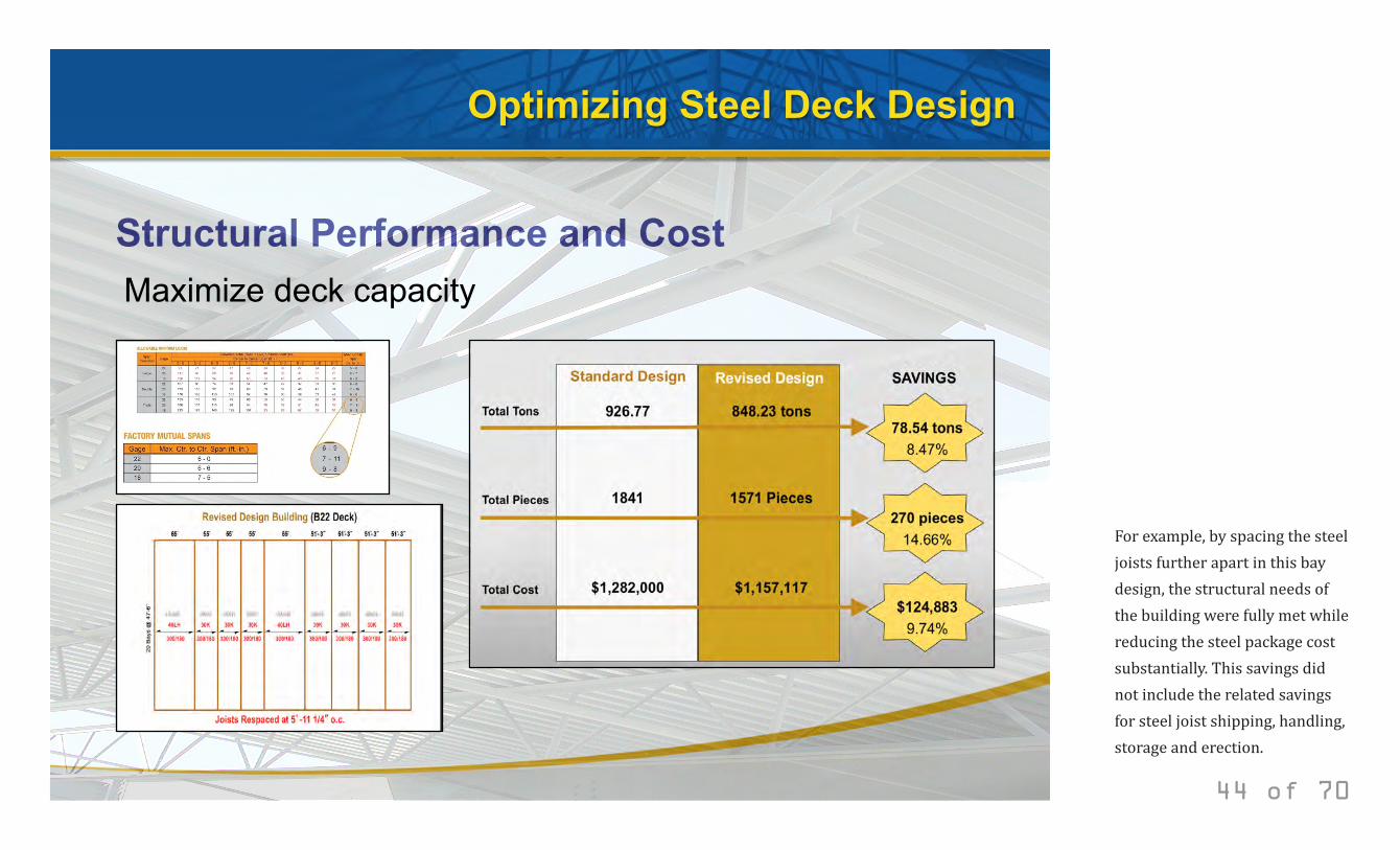
For example, by spacing the steel joists further apart in this bay design, the structural needs of the building were fully met while reducing the steel package cost substantially. This savings did not include the related savings for steel joist shipping, handling, storage and erection.
© 2014 New Millennium Building Systems, LLC All rights reserved.
Optimizing Steel Deck Design
Structural Performance and Cost Specify the deck gauge
45 of 70
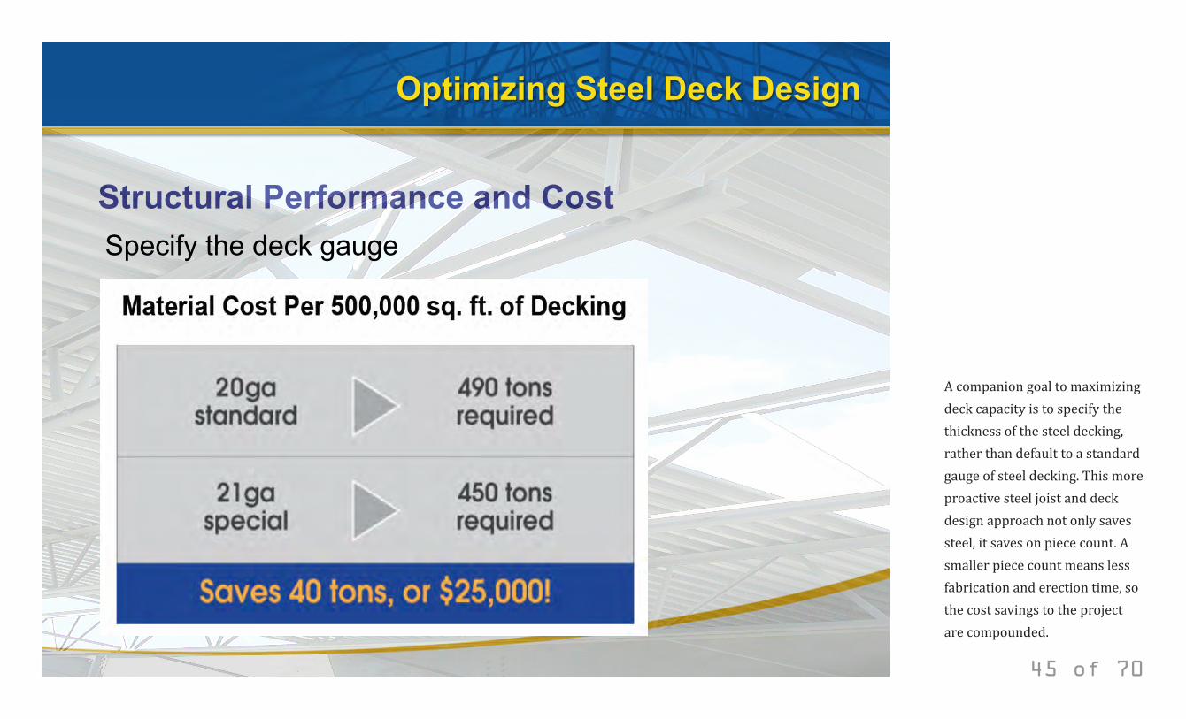
A companion goal to maximizing deck capacity is to specify the thickness of the steel decking, rather than default to a standard gauge of steel decking. This more proactive steel joist and deck design approach not only saves steel, it saves on piece count. A smaller piece count means less fabrication and erection time, so the cost savings to the project are compounded.
© 2014 New Millennium Building Systems, LLC All rights reserved.
Optimizing Steel Deck Design
Structural Performance and Cost Specify the deck gauge
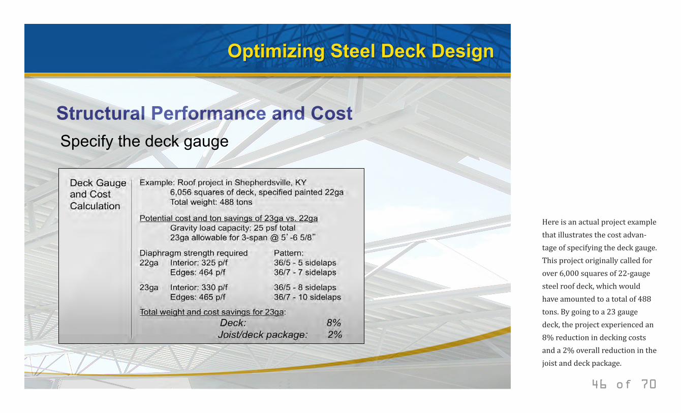
46 of 70
Here is an actual project example that illustrates the cost advan-tage of specifying the deck gauge. This project originally called for over 6,000 squares of 22-gauge steel roof deck, which would have amounted to a total of 488 tons. By going to a 23 gauge deck, the project experienced an 8% reduction in decking costs and a 2% overall reduction in the joist and deck package.
© 2014 New Millennium Building Systems, LLC All rights reserved.
Optimizing Steel Deck Design
Structural Performance and Cost Wide span deck design
47 of 70
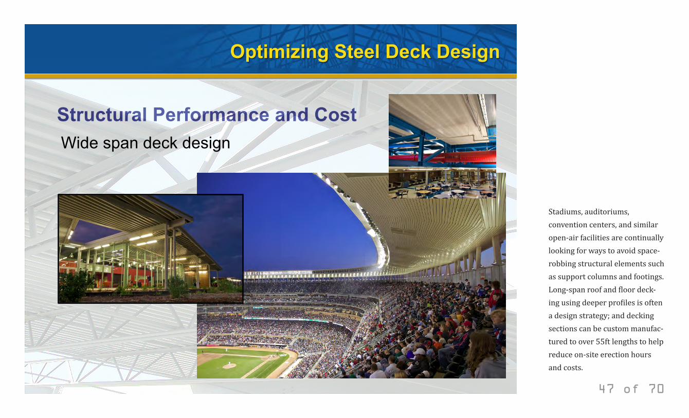
Stadiums, auditoriums, convention centers, and similar open-air facilities are continually looking for ways to avoid space-robbing structural elements such as support columns and footings. Long-span roof and floor deck-ing using deeper profiles is often a design strategy; and decking sections can be custom manufac-tured to over 55ft lengths to help reduce on-site erection hours and costs.
© 2014 New Millennium Building Systems, LLC All rights reserved.
Optimizing Steel Deck Design
Structural Performance and Cost Perimeter deck design
48 of 70
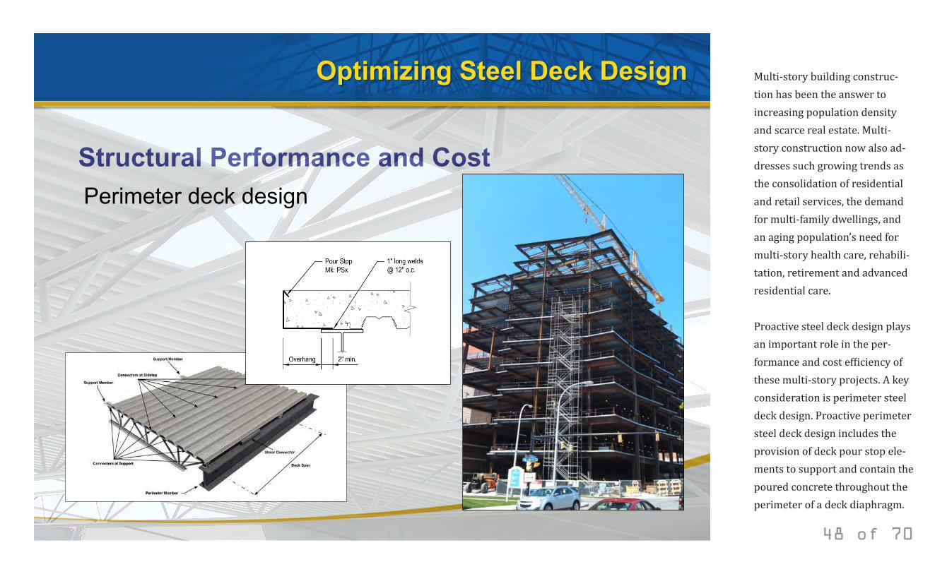
Multi-story building construc-tion has been the answer to increasing population density and scarce real estate. Multi-story construction now also ad-dresses such growing trends as the consolidation of residential and retail services, the demand for multi-family dwellings, and an aging population’s need for multi-story health care, rehabili-tation, retirement and advanced residential care. Proactive steel deck design plays an important role in the per-formance and cost efficiency of these multi-story projects. A key consideration is perimeter steel deck design. Proactive perimeter steel deck design includes the provision of deck pour stop ele-ments to support and contain the poured concrete throughout the perimeter of a deck diaphragm.
© 2014 New Millennium Building Systems, LLC All rights reserved.
Optimizing Steel Deck Design
Structural Performance and Cost Perimeter deck design
49 of 70
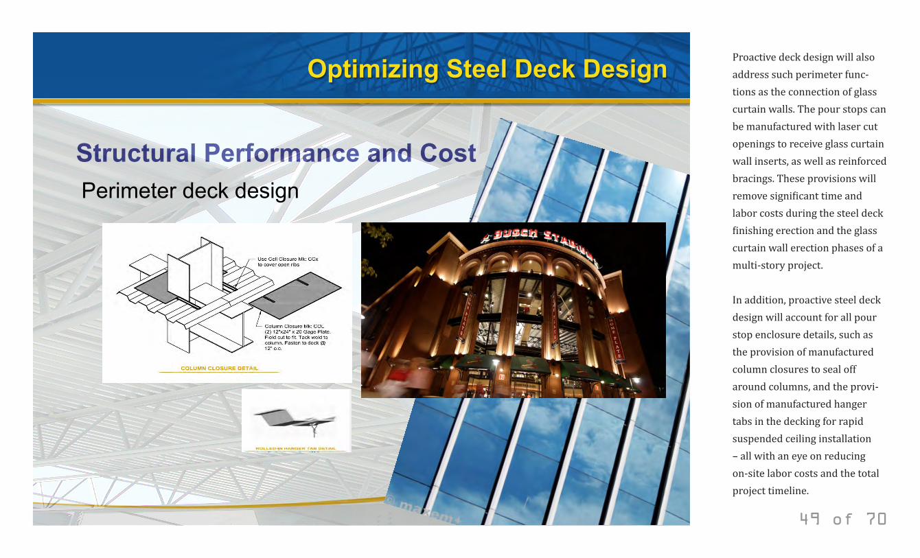
Proactive deck design will also address such perimeter func-tions as the connection of glass curtain walls. The pour stops can be manufactured with laser cut openings to receive glass curtain wall inserts, as well as reinforced bracings. These provisions will remove significant time and labor costs during the steel deck finishing erection and the glass curtain wall erection phases of a multi-story project. In addition, proactive steel deck design will account for all pour stop enclosure details, such as the provision of manufactured column closures to seal off around columns, and the provi-sion of manufactured hanger tabs in the decking for rapid suspended ceiling installation – all with an eye on reducing on-site labor costs and the total project timeline.
© 2014 New Millennium Building Systems, LLC All rights reserved.
Steel Deck Detailing
50 of 70
© 2014 New Millennium Building Systems, LLC All rights reserved.
Steel Deck Detailing
• The role of steel deck detailing
• Examples of deck detailing
• Factory Mutual requirements
• Underwriter’s Laboratory requirements
Steel deck detailing
51 of 70
© 2014 New Millennium Building Systems, LLC All rights reserved.
Steel Deck Detailing
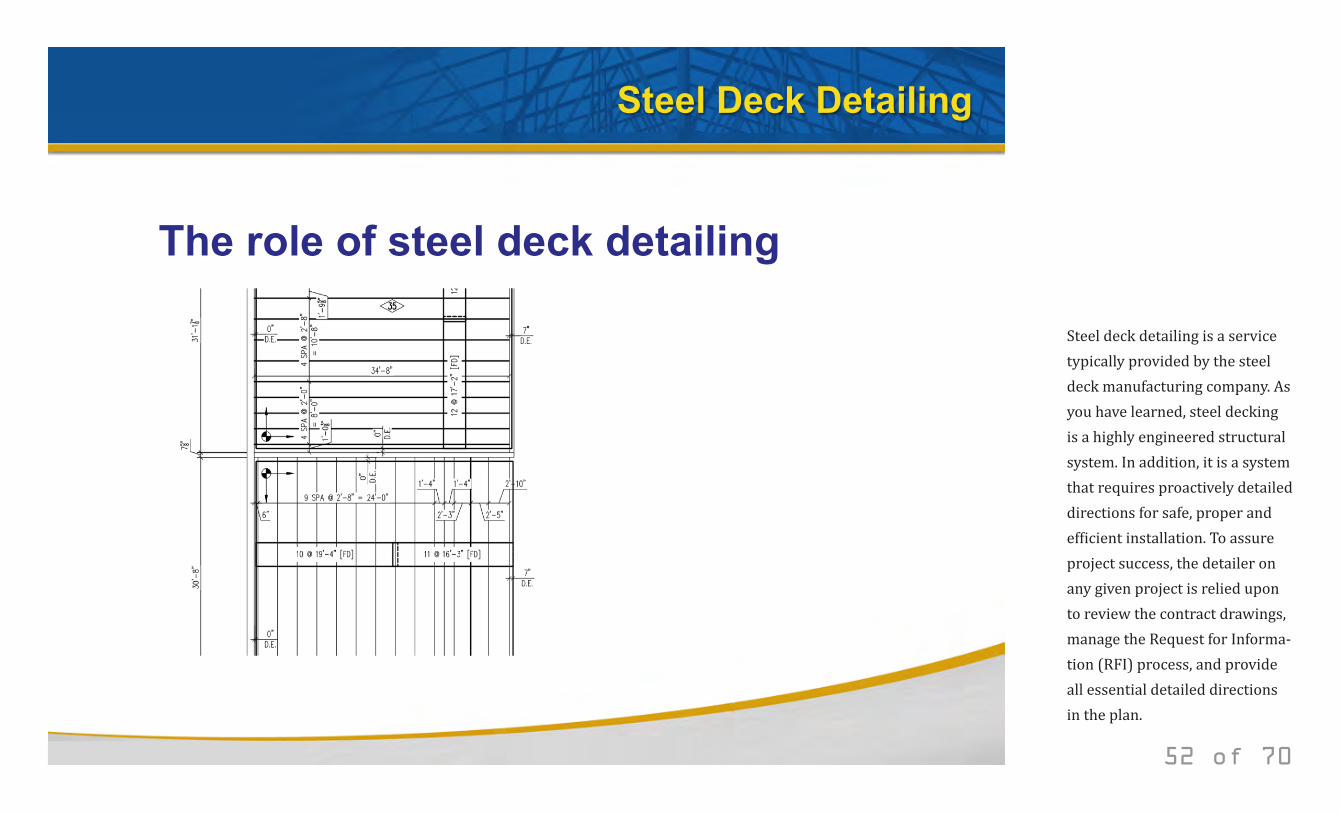
The role of steel deck detailing
52 of 70
Steel deck detailing is a service typically provided by the steel deck manufacturing company. As you have learned, steel decking is a highly engineered structural system. In addition, it is a system that requires proactively detailed directions for safe, proper and efficient installation. To assure project success, the detailer on any given project is relied upon to review the contract drawings, manage the Request for Informa-tion (RFI) process, and provide all essential detailed directions in the plan.
© 2014 New Millennium Building Systems, LLC All rights reserved.
Steel Deck Detailing
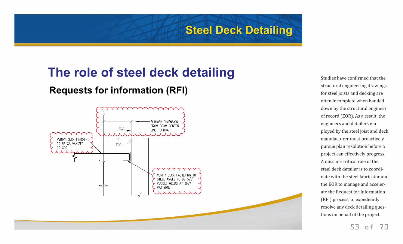
The role of steel deck detailing Requests for information (RFI)
53 of 70
Studies have confirmed that the structural engineering drawings for steel joists and decking are often incomplete when handed down by the structural engineer of record (EOR). As a result, the engineers and detailers em-ployed by the steel joist and deck manufacturer must proactively pursue plan resolution before a project can effectively progress. A mission-critical role of the steel deck detailer is to coordi-nate with the steel fabricator and the EOR to manage and acceler-ate the Request for Information (RFI) process, to expediently resolve any deck detailing ques-tions on behalf of the project.
© 2014 New Millennium Building Systems, LLC All rights reserved.
Steel Deck Detailing
The role of steel deck detailing
Deck attachment
Deck perimeter
Enclosures
Expansion joints
Ridge and valley
Change of deck direction
54 of 70
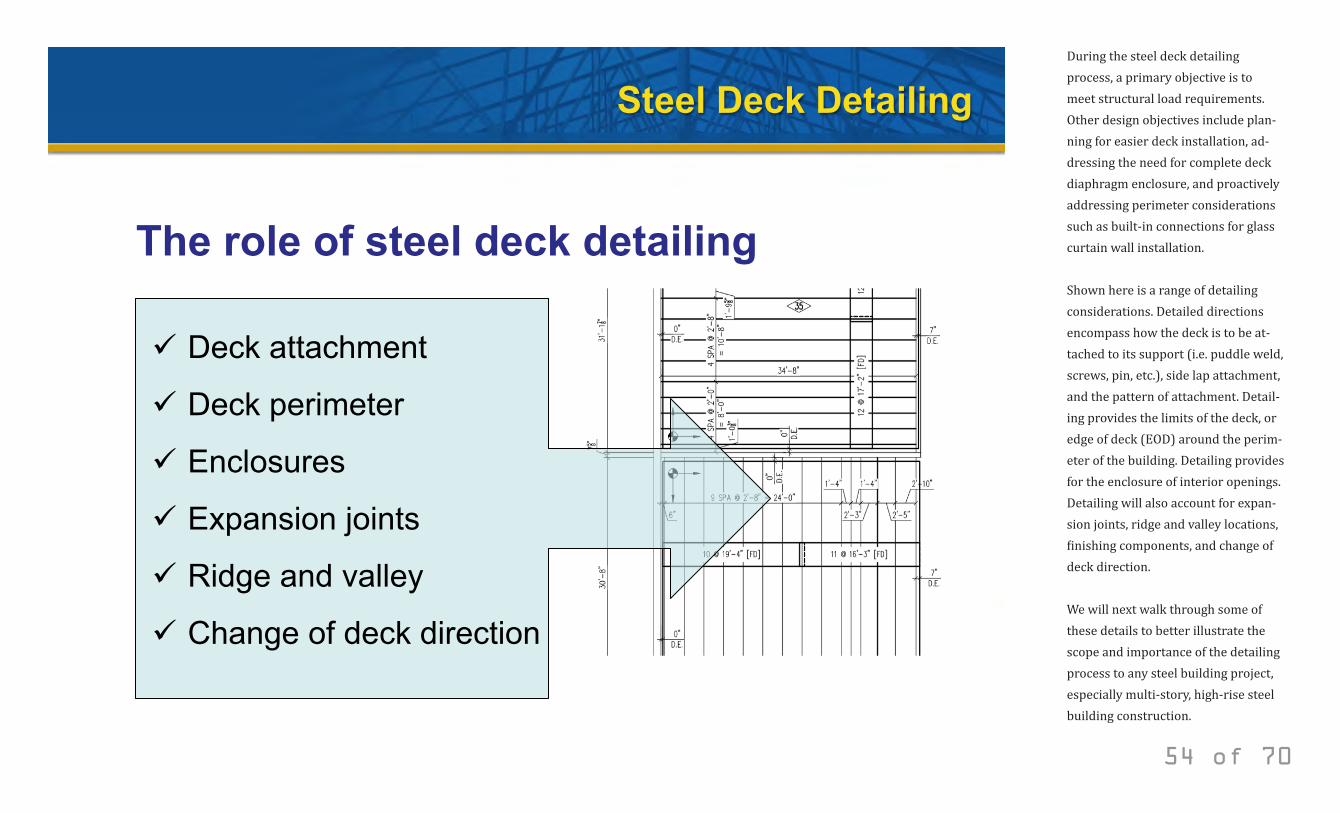
During the steel deck detailing process, a primary objective is to meet structural load requirements. Other design objectives include plan-ning for easier deck installation, ad-dressing the need for complete deck diaphragm enclosure, and proactively addressing perimeter considerations such as built-in connections for glass curtain wall installation. Shown here is a range of detailing considerations. Detailed directions encompass how the deck is to be at-tached to its support (i.e. puddle weld, screws, pin, etc.), side lap attachment, and the pattern of attachment. Detail-ing provides the limits of the deck, or edge of deck (EOD) around the perim-eter of the building. Detailing provides for the enclosure of interior openings. Detailing will also account for expan-sion joints, ridge and valley locations, finishing components, and change of deck direction. We will next walk through some of these details to better illustrate the scope and importance of the detailing process to any steel building project, especially multi-story, high-rise steel building construction.
© 2014 New Millennium Building Systems, LLC All rights reserved.
Steel Deck Detailing
Examples of steel deck detailing Deck starting point
55 of 70
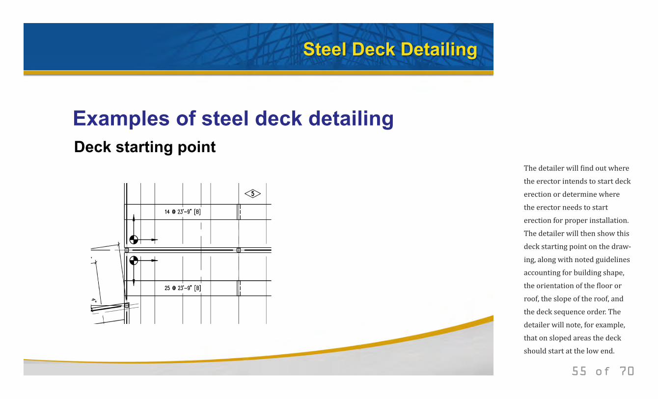
The detailer will find out where the erector intends to start deck erection or determine where the erector needs to start erection for proper installation. The detailer will then show this deck starting point on the draw-ing, along with noted guidelines accounting for building shape, the orientation of the floor or roof, the slope of the roof, and the deck sequence order. The detailer will note, for example, that on sloped areas the deck should start at the low end.
© 2014 New Millennium Building Systems, LLC All rights reserved.
Steel Deck Detailing
Examples of steel deck detailing Roof deck & form deck end lap condition Composite deck end lap condition
56 of 70
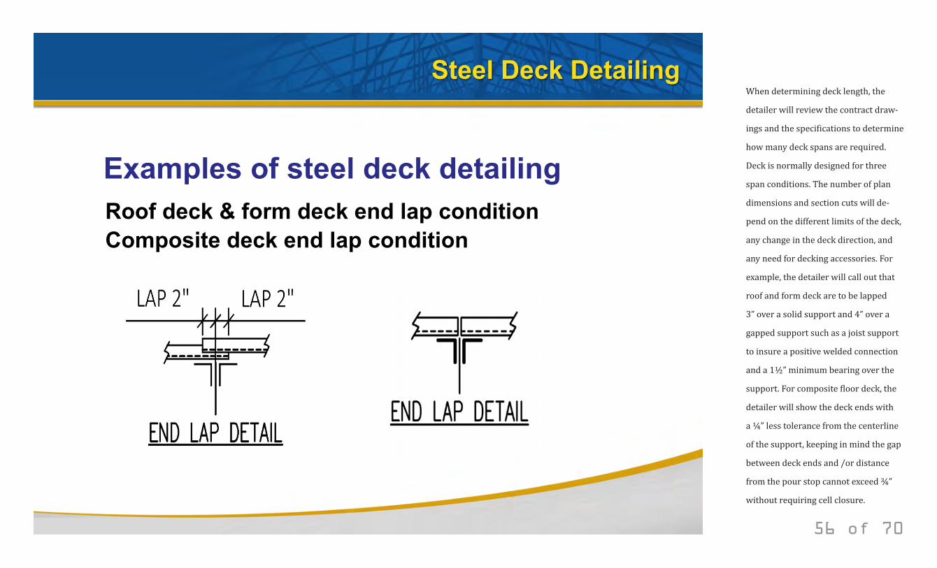
When determining deck length, the
detailer will review the contract draw-
ings and the specifications to determine
how many deck spans are required.
Deck is normally designed for three
span conditions. The number of plan
dimensions and section cuts will de-
pend on the different limits of the deck,
any change in the deck direction, and
any need for decking accessories. For
example, the detailer will call out that
roof and form deck are to be lapped
3” over a solid support and 4” over a
gapped support such as a joist support
to insure a positive welded connection
and a 1½” minimum bearing over the
support. For composite floor deck, the
detailer will show the deck ends with
a ¼” less tolerance from the centerline
of the support, keeping in mind the gap
between deck ends and /or distance
from the pour stop cannot exceed ¾”
without requiring cell closure.
© 2014 New Millennium Building Systems, LLC All rights reserved.
Steel Deck Detailing
Examples of steel deck detailing Deck perimeter – edge of deck (EOD)
Deck Sections
57 of 70
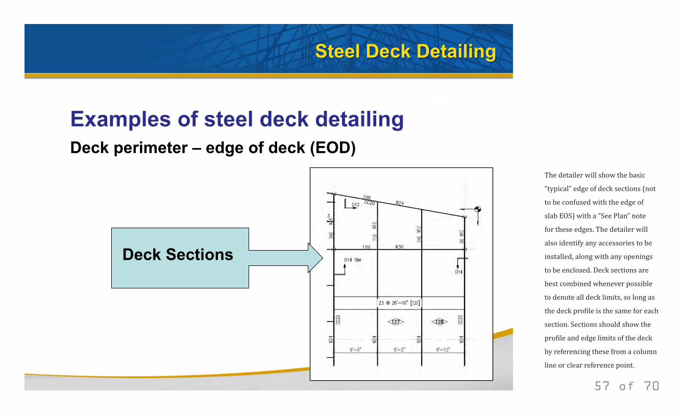
The detailer will show the basic
“typical” edge of deck sections (not
to be confused with the edge of
slab EOS) with a “See Plan” note
for these edges. The detailer will
also identify any accessories to be
installed, along with any openings
to be enclosed. Deck sections are
best combined whenever possible
to denote all deck limits, so long as
the deck profile is the same for each
section. Sections should show the
profile and edge limits of the deck
by referencing these from a column
line or clear reference point.
© 2014 New Millennium Building Systems, LLC All rights reserved.
Steel Deck Detailing
Examples of steel deck detailing Deck perimeter – edge of deck (EOD)
Deck Attachment
58 of 70
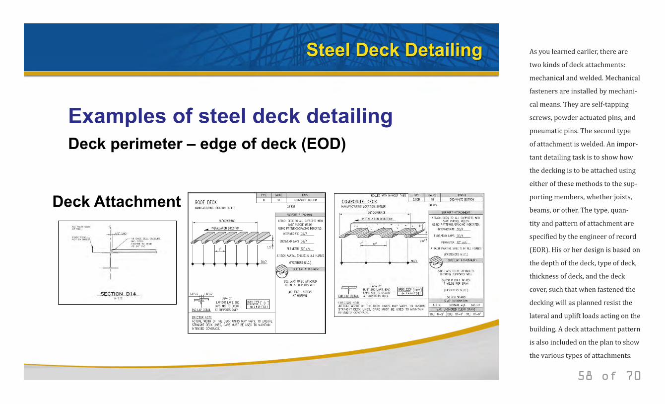
As you learned earlier, there are
two kinds of deck attachments:
mechanical and welded. Mechanical
fasteners are installed by mechani-
cal means. They are self-tapping
screws, powder actuated pins, and
pneumatic pins. The second type
of attachment is welded. An impor-
tant detailing task is to show how
the decking is to be attached using
either of these methods to the sup-
porting members, whether joists,
beams, or other. The type, quan-
tity and pattern of attachment are
specified by the engineer of record
(EOR). His or her design is based on
the depth of the deck, type of deck,
thickness of deck, and the deck
cover, such that when fastened the
decking will as planned resist the
lateral and uplift loads acting on the
building. A deck attachment pattern
is also included on the plan to show
the various types of attachments.
© 2014 New Millennium Building Systems, LLC All rights reserved.
Steel Deck Detailing
Examples of steel deck detailing Deck finishing components
59 of 70
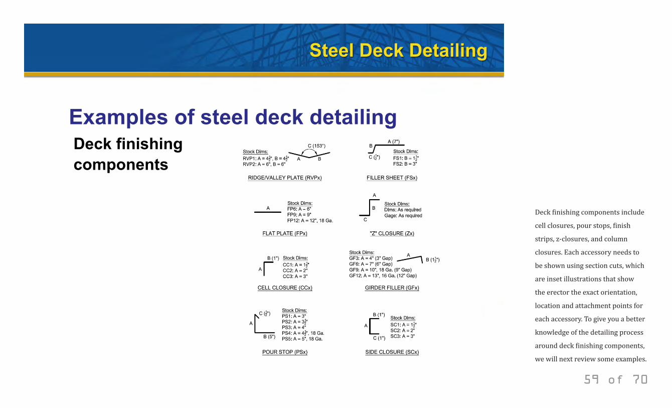
Deck finishing components include
cell closures, pour stops, finish
strips, z-closures, and column
closures. Each accessory needs to
be shown using section cuts, which
are inset illustrations that show
the erector the exact orientation,
location and attachment points for
each accessory. To give you a better
knowledge of the detailing process
around deck finishing components,
we will next review some examples.
© 2014 New Millennium Building Systems, LLC All rights reserved.
Steel Deck Detailing
Examples of steel deck detailing Cell closure
60 of 70
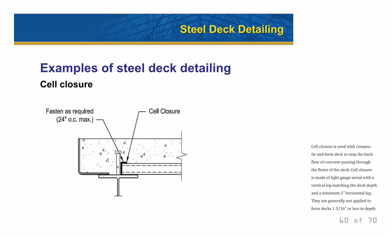
Cell closure is used with compos-
ite and form deck to stop the back
flow of concrete passing through
the flutes of the deck. Cell closure
is made of light gauge metal with a
vertical leg matching the deck depth
and a minimum 1” horizontal leg.
They are generally not applied to
form decks 1 5/16” or less in depth.
© 2014 New Millennium Building Systems, LLC All rights reserved.
Steel Deck Detailing
Examples of steel deck detailing Pour stop
61 of 70
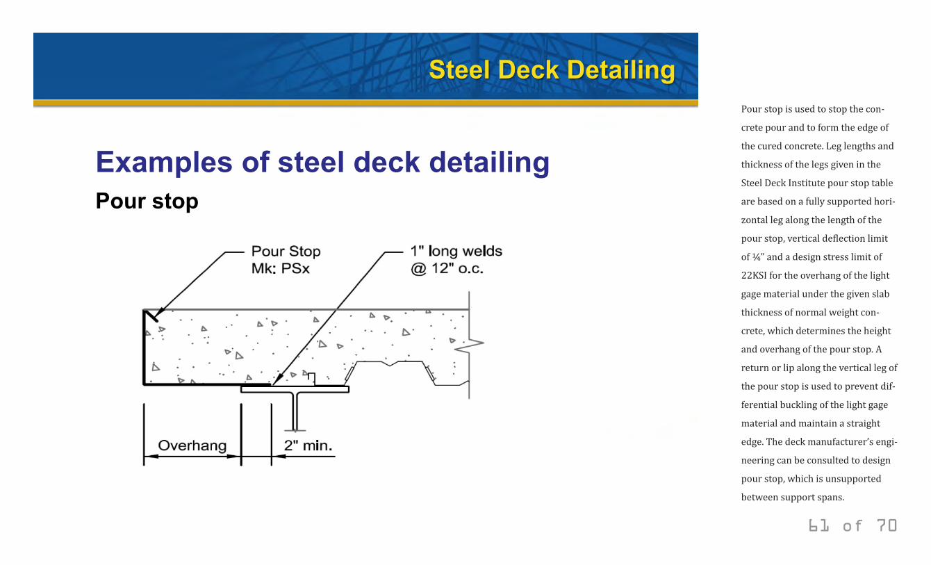
Pour stop is used to stop the con-
crete pour and to form the edge of
the cured concrete. Leg lengths and
thickness of the legs given in the
Steel Deck Institute pour stop table
are based on a fully supported hori-
zontal leg along the length of the
pour stop, vertical deflection limit
of ¼” and a design stress limit of
22KSI for the overhang of the light
gage material under the given slab
thickness of normal weight con-
crete, which determines the height
and overhang of the pour stop. A
return or lip along the vertical leg of
the pour stop is used to prevent dif-
ferential buckling of the light gage
material and maintain a straight
edge. The deck manufacturer’s engi-
neering can be consulted to design
pour stop, which is unsupported
between support spans.
© 2014 New Millennium Building Systems, LLC All rights reserved.
Steel Deck Detailing
Examples of steel deck detailing Finish strip
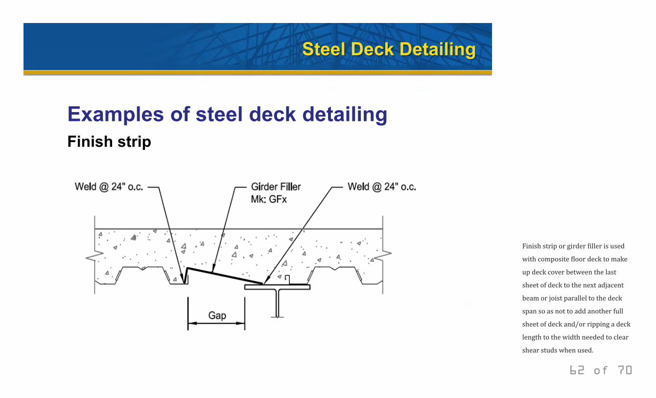
62 of 70
Finish strip or girder filler is used
with composite floor deck to make
up deck cover between the last
sheet of deck to the next adjacent
beam or joist parallel to the deck
span so as not to add another full
sheet of deck and/or ripping a deck
length to the width needed to clear
shear studs when used.

© 2014 New Millennium Building Systems, LLC All rights reserved.
Steel Deck Detailing
Examples of steel deck detailing Z closure
63 of 70
Z-closure is commonly used with
floor deck to stop the pour when
there is a change in deck elevation
between a deck support and a sup-
porting beam flange. A Z-closure
can also be used at the roof to
make-up for deck cover around the
perimeter of the building.
© 2014 New Millennium Building Systems, LLC All rights reserved.
Steel Deck Detailing
Examples of steel deck detailing Column closure
64 of 70
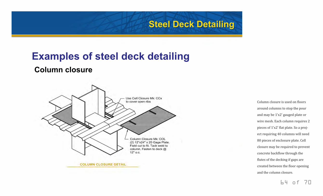
Column closure is used on floors
around columns to stop the pour
and may be 1’x2’ gauged plate or
wire mesh. Each column requires 2
pieces of 1’x2’ flat plate. So a proj-
ect requiring 40 columns will need
80 pieces of enclosure plate. Cell
closure may be required to prevent
concrete backflow through the
flutes of the decking if gaps are
created between the floor opening
and the column closure.
© 2014 New Millennium Building Systems, LLC All rights reserved.
Steel Deck Detailing
Examples of steel deck detailing Rubber closure
65 of 70
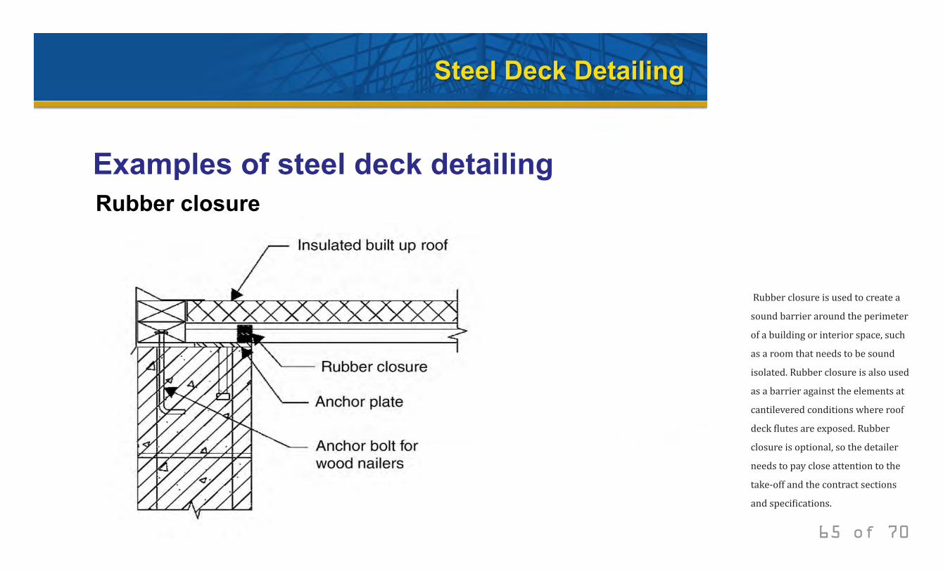
Rubber closure is used to create a
sound barrier around the perimeter
of a building or interior space, such
as a room that needs to be sound
isolated. Rubber closure is also used
as a barrier against the elements at
cantilevered conditions where roof
deck flutes are exposed. Rubber
closure is optional, so the detailer
needs to pay close attention to the
take-off and the contract sections
and specifications.
© 2014 New Millennium Building Systems, LLC All rights reserved.
Steel Deck Detailing
Examples of steel deck detailing Deck bundling
66 of 70
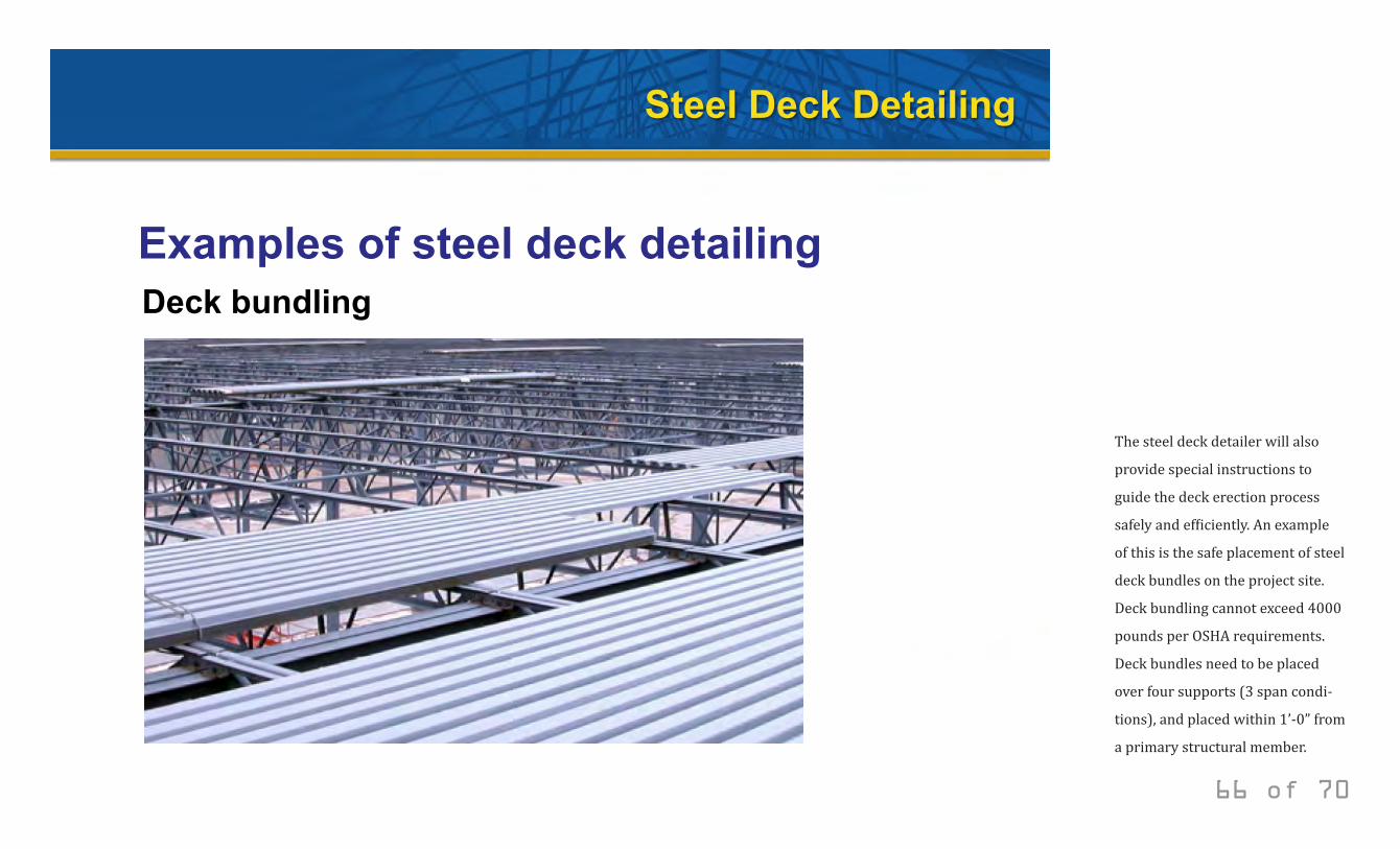
The steel deck detailer will also
provide special instructions to
guide the deck erection process
safely and efficiently. An example
of this is the safe placement of steel
deck bundles on the project site.
Deck bundling cannot exceed 4000
pounds per OSHA requirements.
Deck bundles need to be placed
over four supports (3 span condi-
tions), and placed within 1’-0” from
a primary structural member.
© 2014 New Millennium Building Systems, LLC All rights reserved.
Steel Deck Detailing
Factory Mutual requirements
• Roof Deck Span
• Deck Fastener Spacing
• Perimeter Zone Definition
• Welds and Fastener Recommendations
67 of 70
Another role of the steel deck detailer is to account for any Factory Mutual (FM) compliant provisions in the detailing of the deck erection drawings. FM is an insurance company that insures buildings for natural disasters, such as earthquakes and hurricanes. To control their losses, FM specifies deck design that is based on their research for dif-ferent load conditions, especially wind loads and fire and the behavior it has on buildings. Class 1 and 2 roofs are de-scribed in relation to fire hazards. Class 1-60, 1-90, etc. roofs are described in relation to wind resistance. Listed here are some of the design considerations addressed by FM. Listed here are some examples of Factory Mutual provisions. Roof Deck Span – if Factory Mutual 1-28 is specified, check allowable deck spans per profile. The specifying pro-fessional is advised to consult the deck manufacturer.
Deck Fastening – if the specification references Factory Mutual I-60 thru I-90 Windstorm Classification then the minimum support fastener spacing requirements are 6” on centers at the perimeter and 12” on centers at the building interior. Classifications 1-105 through 1-135 will require Grade 80 steel in addition to more frequent attachments.
© 2014 New Millennium Building Systems, LLC All rights reserved.
Steel Deck Detailing
Factory Mutual requirements
• Roof Deck Span
• Deck Fastener Spacing
• Perimeter Zone Definition
• Welds and Fastener Recommendations
68 of 70
If the perimeter zone is not defined on the contract draw-ings, then use the Factory Mutual definition as the smaller of: (1) 0.1 times the buildings lesser dimension; (2) 0.4 times the eave height; (3) subject to a minimum width of 4 ft. Steel Deck Design Attachment Recommendations – minimum 5/8” diameter welds are used in wind exposure 2; minimum ½” diameter welds are used in wind exposure one. If FMRC-approved deck fasteners are used instead of welds, they should be spaced as stated in the deck manufacturers’ catalogs.
© 2014 New Millennium Building Systems, LLC All rights reserved.
Steel Deck Detailing
UL requirements
• Construction No. 143: Form deck
• Construction No. 155: Form deck, galvanized
• Construction No. 157: F and B deck
69 of 70
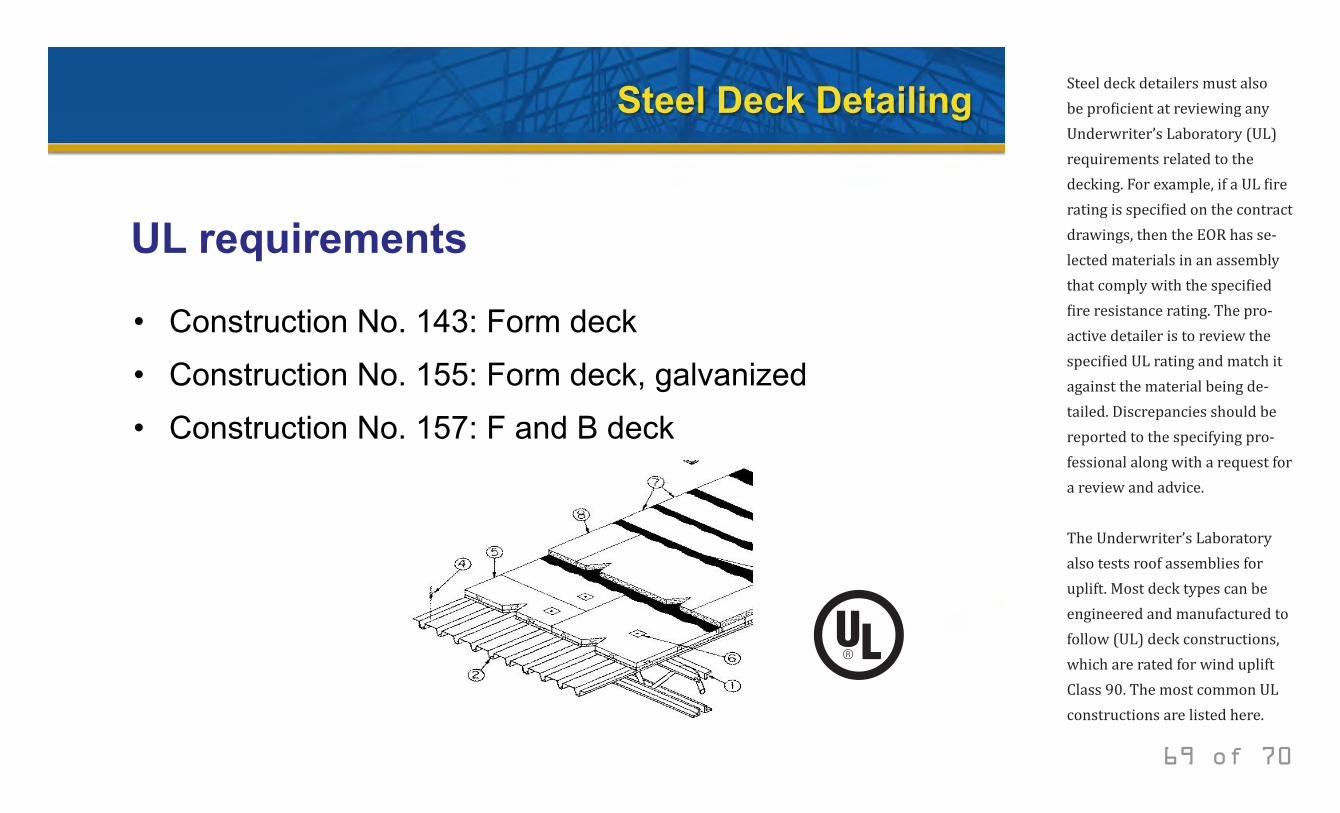
Steel deck detailers must also be proficient at reviewing any Underwriter’s Laboratory (UL) requirements related to the decking. For example, if a UL fire rating is specified on the contract drawings, then the EOR has se-lected materials in an assembly that comply with the specified fire resistance rating. The pro-active detailer is to review the specified UL rating and match it against the material being de-tailed. Discrepancies should be reported to the specifying pro-fessional along with a request for a review and advice. The Underwriter’s Laboratory also tests roof assemblies for uplift. Most deck types can be engineered and manufactured to follow (UL) deck constructions, which are rated for wind uplift Class 90. The most common UL constructions are listed here.
© 2014 New Millennium Building Systems, LLC All rights reserved.
Optimized Steel Deck Design Thank you.
70 of 70