optimization studies for radiation shielding of a ... studies for radiation shielding of a...
TRANSCRIPT
OPTIMIZATION STUDIES FOR RADIATION SHIELDING OF ASUPERCONDUCTING RF CAVITY TEST FACILITY�
Camille M. Ginsburg� and Igor Rakhno, Fermilab, Batavia, IL 60510, USA
Abstract
Test facilities for high-gradient superconducting RF cav-ities must be shielded for particle radiation, which is gen-erated by field emitted electrons in the cavities. A majorchallenge for the shielding design is associated with un-certainty in modeling the field emission. In this work, asemi-empirical method that allows us to predict the inten-sity of the generated field emission is described. Spatial,angular and energy distributions of the generated radiationare calculated with the FISHPACT code [1]. The MonteCarlo code MARS15 [2] is used for modeling the radi-ation transport in matter. The detailed distributions of thegenerated field emission are used for studies with 9-cell 1.3GHz superconducting RF cavities in the Fermilab VerticalCavity Test Facility. This approach allows us to minimizethe amount of shielding inside cryostat which is an essen-tial operational feature.
INTRODUCTION
The vertical cavity test facility (VCTF) for supercon-ducting RF (SRF) cavities at Fermilab has been in oper-ation since 2007. The facility currently consists of a singlevertical test cryostat VTS1. Radiation shielding for VTS1was designed for single 9-cell 1.3 GHz cavities using a sim-plified field emission model as the radiation source [3, 4].Two additional cryostats with common design, VTS2&3,are being procured, and are sized such that six 9-cell cav-ities can be installed per cryostat (see Fig. 1). VCTF testthroughput will be gained through common cooldown andwarmup time, with cavities tested sequentially. Space foradditional shielding, either internal or external to the cryo-stat, is limited. An evaluation of the radiation shielding wasperformed, to minimally extend the VTS1 shielding designto a six-cavity configuration in VTS2&3 which attenuatesradiation consistent with personnel safety standards.
An essential part of the present analysis is in using realis-tic models for cavity geometry and spatial, angular and en-ergy distributions of field-emitted electrons inside the cav-ities. The calculations were performed with the computercodes FISHPACT and MARS15.
GEOMETRY MODEL
The full cross section and fragments of the three-dimensional shielding model, showing a simple extensionto the VTS1 shielding, are shown in Figs. 2 and 3, respec-
�Work supported by Fermi Research Alliance, LLC under contractDE-AC02-07CH11359 with the U.S. Department of Energy.
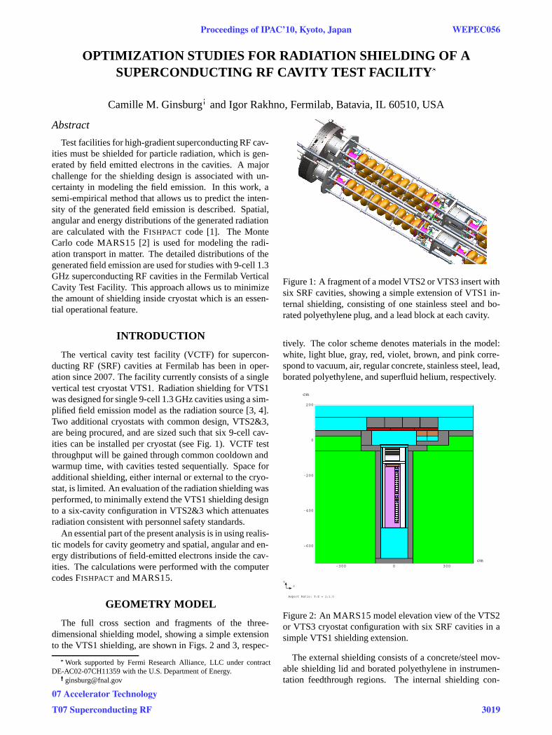
Figure 1: A fragment of a model VTS2 or VTS3 insert withsix SRF cavities, showing a simple extension of VTS1 in-ternal shielding, consisting of one stainless steel and bo-rated polyethylene plug, and a lead block at each cavity.
tively. The color scheme denotes materials in the model:white, light blue, gray, red, violet, brown, and pink corre-spond to vacuum, air, regular concrete, stainless steel, lead,borated polyethylene, and superfluid helium, respectively.
-600
-400
-200
0
200
cm
-300 0 300cm
Aspect Ratio: Y:Z = 1:1.0
Z
Y
Figure 2: An MARS15 model elevation view of the VTS2or VTS3 cryostat configuration with six SRF cavities in asimple VTS1 shielding extension.
The external shielding consists of a concrete/steel mov-able shielding lid and borated polyethylene in instrumen-tation feedthrough regions. The internal shielding con-
Proceedings of IPAC’10, Kyoto, Japan WEPEC056
07 Accelerator Technology
T07 Superconducting RF 3019
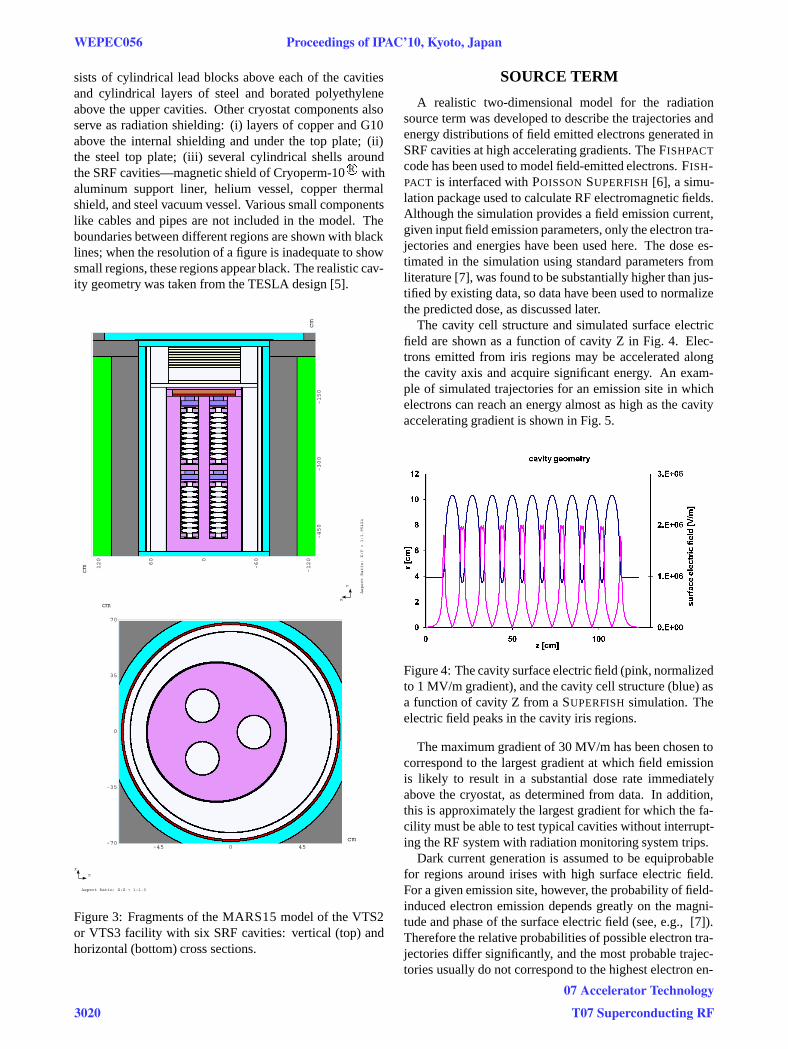
sists of cylindrical lead blocks above each of the cavitiesand cylindrical layers of steel and borated polyethyleneabove the upper cavities. Other cryostat components alsoserve as radiation shielding: (i) layers of copper and G10above the internal shielding and under the top plate; (ii)the steel top plate; (iii) several cylindrical shells aroundthe SRF cavities—magnetic shield of Cryoperm-10 R� withaluminum support liner, helium vessel, copper thermalshield, and steel vacuum vessel. Various small componentslike cables and pipes are not included in the model. Theboundaries between different regions are shown with blacklines; when the resolution of a figure is inadequate to showsmall regions, these regions appear black. The realistic cav-ity geometry was taken from the TESLA design [5].
-120
-600
60
120
cm
-450
-300
-150
cm
Aspect Ratio: X:Y = 1:1.95424
Y
X
-70
-35
0
35
70
cm
-45 0 45cm
Aspect Ratio: X:Z = 1:1.0
Z
X
Figure 3: Fragments of the MARS15 model of the VTS2or VTS3 facility with six SRF cavities: vertical (top) andhorizontal (bottom) cross sections.
SOURCE TERM
A realistic two-dimensional model for the radiationsource term was developed to describe the trajectories andenergy distributions of field emitted electrons generated inSRF cavities at high accelerating gradients. The FISHPACT
code has been used to model field-emitted electrons. FISH-PACT is interfaced with POISSON SUPERFISH [6], a simu-lation package used to calculate RF electromagnetic fields.Although the simulation provides a field emission current,given input field emission parameters, only the electron tra-jectories and energies have been used here. The dose es-timated in the simulation using standard parameters fromliterature [7], was found to be substantially higher than jus-tified by existing data, so data have been used to normalizethe predicted dose, as discussed later.
The cavity cell structure and simulated surface electricfield are shown as a function of cavity Z in Fig. 4. Elec-trons emitted from iris regions may be accelerated alongthe cavity axis and acquire significant energy. An exam-ple of simulated trajectories for an emission site in whichelectrons can reach an energy almost as high as the cavityaccelerating gradient is shown in Fig. 5.
Figure 4: The cavity surface electric field (pink, normalizedto 1 MV/m gradient), and the cavity cell structure (blue) asa function of cavity Z from a SUPERFISH simulation. Theelectric field peaks in the cavity iris regions.
The maximum gradient of 30 MV/m has been chosen tocorrespond to the largest gradient at which field emissionis likely to result in a substantial dose rate immediatelyabove the cryostat, as determined from data. In addition,this is approximately the largest gradient for which the fa-cility must be able to test typical cavities without interrupt-ing the RF system with radiation monitoring system trips.
Dark current generation is assumed to be equiprobablefor regions around irises with high surface electric field.For a given emission site, however, the probability of field-induced electron emission depends greatly on the magni-tude and phase of the surface electric field (see, e.g., [7]).Therefore the relative probabilities of possible electron tra-jectories differ significantly, and the most probable trajec-tories usually do not correspond to the highest electron en-
WEPEC056 Proceedings of IPAC’10, Kyoto, Japan
3020
07 Accelerator Technology
T07 Superconducting RF
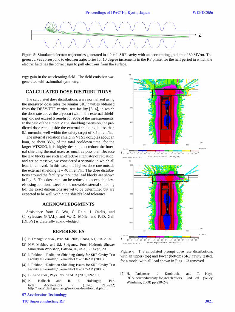
Figure 5: Simulated electron trajectories generated in a 9-cell SRF cavity with an accelerating gradient of 30 MV/m. Thegreen curves correspond to electron trajectories for 10 degree increments in the RF phase, for the half period in which theelectric field has the correct sign to pull electrons from the surface.
ergy gain in the accelerating field. The field emission wasgenerated with azimuthal symmetry.
CALCULATED DOSE DISTRIBUTIONS
The calculated dose distributions were normalized usingthe measured dose rates for similar SRF cavities obtainedfrom the DESY/TTF vertical test facility [3, 4], in whichthe dose rate above the cryostat (within the external shield-ing) did not exceed 5 rem/hr for 90% of the measurements.In the case of the simple VTS1 shielding extension, the pre-dicted dose rate outside the external shielding is less than0.1 mrem/hr, well within the safety target of �5 mrem/hr.
The internal radiation shield in VTS1 occupies about anhour, or about 35%, of the total cooldown time; for thelarger VTS2&3, it is highly desirable to reduce the inter-nal shielding thermal mass as much as possible. Becausethe lead blocks are such an effective attenuator of radiation,and are so massive, we considered a scenario in which alllead is removed. In this case, the highest dose rate outsidethe external shielding is �40 mrem/hr. The dose distribu-tions around the facility without the lead blocks are shownin Fig. 6. This dose rate can be reduced to acceptable lev-els using additional steel on the movable external shieldinglid; the exact dimensions are yet to be determined but areexpected to be well within the shield’s load tolerance.
ACKNOWLEDGMENTS
Assistance from G. Wu, C. Reid, J. Ozelis, andC. Sylvester (FNAL), and W.-D. Moller and P.-D. Gall(DESY) is gratefully acknowledged.
REFERENCES
[1] E. Donoghue et al., Proc. SRF2005, Ithaca, NY, Jun. 2005.
[2] N.V. Mokhov and S.I. Striganov, Proc. Hadronic ShowerSimulation Workshop, Batavia, IL, USA, 6-8 Sept., 2006.
[3] I. Rakhno, “Radiation Shielding Study for SRF Cavity TestFacility at Fermilab,” Fermilab-TM-2350-AD (2006).
[4] I. Rakhno, “Radiation Shielding Issues for SRF Cavity TestFacility at Fermilab,” Fermilab-TM-2367-AD (2006).
[5] B. Aune et al., Phys. Rev. STAB 3 (2000) 092001.
[6] K. Halbach and R. F. Holsinger, Par-ticle Accelerators 7 (1976) 213-222;http://laacg1.lanl.gov/laacg/services/download sf.phtml.
-600
-400
-200
0
200
cm
-300 0 300cm
101010
910
810
710
610
510
410
310
210
110
010
-110
-210
-310
-410
-510
-6
Aspect Ratio: Y:Z = 1:1.0
1.1e+09 0.0e+00
Z
Y
Dose equivalent (mrem/hr)
-600
-400
-200
0
200
cm
-300 0 300cm
101010
910
810
710
610
510
410
310
210
110
010
-110
-210
-310
-410
-510
-6
Aspect Ratio: Y:Z = 1:1.0
6.2e+08 0.0e+00
Z
Y
Dose equivalent (mrem/hr)
Figure 6: The calculated prompt dose rate distributionswith an upper (top) and lower (bottom) SRF cavity tested,for a model with all lead shown in Figs. 1-3 removed.
[7] H. Padamsee, J. Knobloch, and T. Hays,RF Superconductivity for Accelerators, 2nd ed. (Wiley,Weinheim, 2008) pp.230-242.
Proceedings of IPAC’10, Kyoto, Japan WEPEC056
07 Accelerator Technology
T07 Superconducting RF 3021