optimisation of the transfer carriage structure - uliege · optimisation of the transfer carriage...
TRANSCRIPT
Optimisation of the transfer carriage structure Thesis Report
Author: Vladimir Škorić
Supervisors: Jean-François Demonceau & Jean-Pierre Jaspart (University of Liège)
Anthony Fringuellini & Olivier Pensis (Drever International)
University: University of Liège
University: University of Liège Date: 06.01.2017

i
Acknowledgement
Special thanks are addressed to Prof. Jean-Pierre Jaspart and Associate Prof. Jean-François Demonceau, promoters of the thesis and my research supervisors for their professional guidance, constructive advice and patience. My gratitude goes also to Anthony Fringuellini and Olivier Pensis from Drever International S.A. Liège, for supervising my work, sharing data and technical experience. I would like to express a great appreciation to the European Commission for the financial support during my studies in the Erasmus Mundus Programme SUSCOS_M, what would be very difficult without their support. I would like to thank my SUSCOS colleagues for their feedback, cooperation and of course friendship.
Last but not least, I would like to thank my family for supporting me spiritually throughout writing this thesis and my life in general.

ii
Summary
This work has been carried out in collaboration with DREVER International S.A. located in Liège. Drever International is a market leader for continuous annealing furnaces and galvanizing plants for steel and stainless steel strip. In the heat treatment of strips (automotive qualities), it is necessary to use a transfer carriage in order to translate an induction furnace (with a weight of about 80 tons). Currently, this carriage has several overhangs. It consists of girder beams and comprises a system to compensate torsion efforts. The design of this equipment is guided by the respect of deflection criteria. The aim of this thesis is to improve the structural system and to optimize the transfer carriage structure. After studying the current solution, eight new solutions are proposed at the pre-design stage. All of them are studied parametrically analyzing their advantages and disadvantages what leads to the selection of the solution for the detailed design. The selected solution is composed of planar trusses made of hollow sections instead of built-up box girders used in the initial solution. Two variants of the selected solution are studied in detail. As a result, both variants of the selected solution ensure considerable material savings compared to the current solution, as well as some simplifications related to the manufacturing of the structure.

iii
List of symbols
Latin letters: A - Area of a cross-section Anet - Net area of a cross-section Ant - Net area subjected to tension (figuring in the block tearing resistance formula) Anv - Net area subjected to shear (figuring in the block tearing resistance formula) Av - Shear area of a cross-section a - Throat thickness of a fillet weld beq - Equivalent single bracing width e - Eccentricity between the bolt row and the axis of the angle E - Modulus of elasticity Fb,Rd - Design bearing resistances of a plate per bolt FRd - Splice joint factored resistance Ft,Rd - Design tensile resistance of a bolt fu - Ultimate tensile strength of steel material Fv,Rd - Design resistance of a single bolt per shear plane fy - Yield strength of steel material G - Shear modulus heq- Equivalent single bracing length I - second moment of area L - System length of a member Lcr - Critical buckling length of a member leff - Whitmore effective width MEd - Design bending moment Mip,1,Rd - Design in-plane moment resistance of a plate connected to the RHS chord MRd - Design value of the resistance to bending moments n - Number of bolts in a joint Nb,Rd - Design buckling resistance of a member NEd - Design axial force NEd,eff - Hypothetical effective axial load (splice joints) Ni,Rd - Design resistance of a joint in lattice girder made of hollow sections NRd - Design values of the resistance to axial forces T - Applied torque Tf - Actual total bolt tension (splice joints) tp - Gusset plate thickness tsp - Stiffening plate thickness Vb,Rd - Bearing resistance of a bolt group VEd - Design shear force Veff,Rd - Block tearing resistance of a bolt group VL - Shear resistance of an overlap joint in the longitudinal direction VRd - Design value of the resistance to shear forces Vv,Rd - Bolt group resistance to shear Wel - Elastic section modulus of a cross-section Wpl - Plastic section modulus of a cross-section z - Vertical displacement
iv
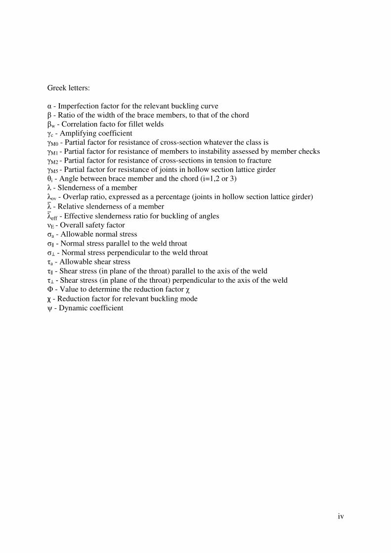
Greek letters: α - Imperfection factor for the relevant buckling curve β - Ratio of the width of the brace members, to that of the chord βw - Correlation facto for fillet welds γc - Amplifying coefficient γM0 - Partial factor for resistance of cross-section whatever the class is γM1 - Partial factor for resistance of members to instability assessed by member checks γM2 - Partial factor for resistance of cross-sections in tension to fracture γM5 - Partial factor for resistance of joints in hollow section lattice girder θi - Angle between brace member and the chord (i=1,2 or 3) λ - Slenderness of a member λov - Overlap ratio, expressed as a percentage (joints in hollow section lattice girder) λ� - Relative slenderness of a member λ�eff - Effective slenderness ratio for buckling of angles νE - Overall safety factor σa - Allowable normal stress σ∥ - Normal stress parallel to the weld throat σ⊥ - Normal stress perpendicular to the weld throat τa - Allowable shear stress τ∥ - Shear stress (in plane of the throat) parallel to the axis of the weld τ⊥ - Shear stress (in plane of the throat) perpendicular to the axis of the weld Φ - Value to determine the reduction factor χ χ - Reduction factor for relevant buckling mode ψ - Dynamic coefficient

v
Table of contents
Acknowledgement ...................................................................................................................... i
Summary .................................................................................................................................... ii
List of symbols ......................................................................................................................... iii
Table of contents ........................................................................................................................ v
List of figures ........................................................................................................................... vii
List of tables .............................................................................................................................. ix
1. Introduction .................................................................................................................... 1
2. Study of the initial solution ............................................................................................ 2
2.1. General layout and dimensions of the structure ...................................................... 2
2.2. Standards applicable to cranes and classification of the structure ........................... 5
2.3. Calculation assumptions .......................................................................................... 9
2.4. Loads and combinations of loads .......................................................................... 10
2.4.1. Dead weight (SG) ............................................................................................... 10
2.4.2. Working loads (SL) ............................................................................................ 11
2.4.3. Loads due to horizontal motions ........................................................................ 12
2.4.4. Other actions ...................................................................................................... 13
2.4.5. Combinations of loads ....................................................................................... 13
2.5. Results ................................................................................................................... 14
2.6. Model for the calibration and development of a new concept .............................. 17
3. Pre-design of proposed solutions ................................................................................. 20
3.1. Solution 1 ............................................................................................................... 21
3.1.1. General layout .................................................................................................... 21
3.1.2. Results, parametric studies and remarks ............................................................ 22
3.2. Solution 2 ............................................................................................................... 23
3.2.1. General layout .................................................................................................... 23
3.2.2. Results, parametric studies and remarks ............................................................ 24
3.3. Solution 3 ............................................................................................................... 30
3.3.1. General layout .................................................................................................... 30
3.3.2. Results, parametric studies and remarks ............................................................ 31
3.4. Solution 4 ............................................................................................................... 33
3.4.1. General layout .................................................................................................... 33
3.4.2. Results, parametric studies and remarks ............................................................ 35
3.5. Solution 5 ............................................................................................................... 37
3.5.1. General layout .................................................................................................... 37
3.5.2. Results, parametric studies and remarks ............................................................ 38
vi
3.6. Solution 6 ............................................................................................................... 41
3.6.1. General layout .................................................................................................... 41
3.6.2. Results, parametric studies and remarks ............................................................ 42
3.7. Solution 7 ............................................................................................................... 45
3.7.1. General layout .................................................................................................... 45
3.7.2. Results, parametric studies and remarks ............................................................ 46
3.8. Solution 8 ............................................................................................................... 48
3.8.1. General layout .................................................................................................... 48
3.8.2. Results, parametric studies and remarks ............................................................ 49
3.9. Overall comparison and selection of the solution for the detailed design ............. 50
4. Detailed design of the selected solutions ..................................................................... 54
4.1. Welded solution made completely of hollow sections (Solution 6-1) ................... 54
4.1.1. Improvements and final layout of the structure ................................................. 54
4.1.2. Serviceability limit states ................................................................................... 57
4.1.3. Ultimate limit states ........................................................................................... 58
4.1.3.1. Design of cross-sections ................................................................................. 58
4.1.3.2. Stability of structural members ...................................................................... 59
4.1.4. Design of joints .................................................................................................. 61
4.1.4.1. Generalities related to joints in hollow section lattice structures ................... 61
4.1.4.2. Unidirectional K joints ................................................................................... 63
4.1.4.3. Overlap KT joints ........................................................................................... 64
4.1.4.4. Site joints ........................................................................................................ 65
4.1.5. Material specification......................................................................................... 69
4.2. Bolted solution made of hollow section chords and angles as braces (Solution 6-2) ......................................................................................... 70
4.2.1. Improvements and final layout of the structure ................................................. 70
4.2.2. Serviceability limit states ................................................................................... 72
4.2.3. Ultimate limit states ........................................................................................... 72
4.2.3.1. Design of cross-sections ................................................................................. 72
4.2.3.2. Stability of structural members ...................................................................... 73
4.2.4. Design of joints .................................................................................................. 74
4.2.4.1. Brace members connected by bolts ................................................................ 74
4.2.4.2. Gusset plates ................................................................................................... 75
4.2.4.3. Site joints ........................................................................................................ 79
4.2.5. Material specification......................................................................................... 80
4.3. Final comparison between the solutions ................................................................ 81
5. Conclusions .................................................................................................................. 82

vii
References ................................................................................................................................ 83
A.Annex A ............................................................................................................. 84
B.Annex B ........................................................................................................... 118
List of figures
Figure 2.1: General layout and designation (source: Drever calculation sheets) ................ 2 Figure 2.2: Runway beam (cross-section) ........................................................................... 3 Figure 2.3: Carriage assembly-3D view (source: Drever calculation sheets) ..................... 3 Figure 2.4: Carriage structure-elevation (source: Drever calculation sheets) ..................... 4 Figure 2.5:Scheme - axes of the structural members ........................................................... 4 Figure 2.6: Loading from the platforms applied on the carriage structure ........................ 10 Figure 2.7: Loading from the caissons-3D view (source: Drever calculation sheets) ....... 11 Figure 2.8: Loading from the inductor-3D view (source: Drever calculation sheets) ....... 11 Figure 2.9: Loading (caissons and ducts) .......................................................................... 11 Figure 2.10: Loading (inductor) ........................................................................................ 11 Figure 2.11: Inertial forces due to horizontal motions: step-by-step procedure ................ 12 Figure 2.12: Local stresses (Von Mises) for load combination X3/X4 (src: Drever) ......... 14 Figure 2.13: Overall distribution of stresses for load combination X1 (src: Drever) ........ 15 Figure 2.14: Overall distribution of stresses for load combination X2 (src Drever) .......... 15 Figure 2.15: Overall distribution of stresses for load combination X3/X4 (src: Drever) ... 15 Figure 2.16: Deformed model of the structure for load combination X3 ........................... 16 Figure 2.17: Model for the calibration - 3D view .............................................................. 18 Figure 2.18: Deformed model of the structure .................................................................. 18 Figure 2.19: Vertical and horizontal reactions - designation ............................................. 19 Figure 2.20: Model without the brackets - 3D view .......................................................... 20 Figure 3.1: Solution 1- 3D view, top side .......................................................................... 21 Figure 3.2: Solution 1 - 3D view, bottom side .................................................................. 21 Figure 3.3: Solution 2 - 3D view ....................................................................................... 24 Figure 3.4: Existing columns and ties (source: Drever calculation sheets) ....................... 24 Figure 3.5: Diagram area multiplier vs deflections [mm] ................................................. 27 Figure 3.6: Horizontal shifting of nodes - designation ...................................................... 27 Figure 3.7: Diagram node shift [m] vs deflections [mm] .................................................. 28 Figure 3.8: Vertical shifting of nodes - designation .......................................................... 28 Figure 3.9: : Diagram node shift [m] vs deflections [mm] ................................................ 29 Figure 3.10: Resolving force N to the horizontal and vertical component ........................ 29 Figure 3.11: Solution 3 - 3D view ..................................................................................... 30 Figure 3.12: Solution 3 - 2D view (elevation) ................................................................... 30 Figure 3.13: Moment of inertia - bowstring structure ....................................................... 33 Figure 3.14: Solution 4 - 3D view ..................................................................................... 34 Figure 3.15: Solution 4 - dimensions ................................................................................. 34 Figure 3.16: Solution 4 - horizontal reactions (designation) ............................................. 34 Figure 3.17: Solution 4 - example of a complex joint ....................................................... 36 Figure 3.18: Solution 4 - complete carriage assembly (source: Drever) ........................... 37 Figure 3.19: : Solution 5 - 3D view ................................................................................... 38 Figure 3.20: Solution 5 - dimensions ................................................................................. 38 Figure 3.21: Solution 5 - example of a simple joint ......................................................... 40 Figure 3.22: Solution 5 - example of a complex joint ...................................................... 40 Figure 3.23: Solution 5 - complete carriage assembly (source: Drever) ........................... 40
viii
Figure 3.24: Solution 5 - bottom chord (source: Drever) .................................................. 41 Figure 3.25: Solution 6 - 3D view and cross-sectional dimensions .................................. 42 Figure 3.26: Joint at the intersection of the perpendicular beams ..................................... 43 Figure 3.27: Solution 6 - coupled trusses - 3D view ......................................................... 44 Figure 3.28: Solution 7 - 3D view and cross-sectional dimensions .................................. 45 Figure 3.29: Solution 7 - structure without the diagonal next to the vertical support ....... 47 Figure 3.30: Solution 7 - structure without the diagonals at the intersections .................. 47 Figure 3.31: Solution 8 - 3D view and cross-sectional dimensions .................................. 48 Figure 3.32: Solution 8 - coupled Vierendeel trusses - 3D view ....................................... 50 Figure 4.1: Solution 6-1, improved structural layout - 3D view ....................................... 55 Figure 4.2: Solution 6-1, connecting beam - 3D view ...................................................... 56 Figure 4.3: Solution 6-1, connecting beam - 3D view ...................................................... 56 Figure 4.4: Solution 6-1, brackets - detail ......................................................................... 56 Figure 4.5: Solution 6-1, brackets - detail ......................................................................... 57 Figure 4.6: Solution 6-1, deformed model for load combination X3 ................................. 57 Figure 4.7: Fillet weld - stresses ........................................................................................ 63 Figure 4.8: Overlap KT joint ............................................................................................. 64 Figure 4.9: Site joints - Option C ....................................................................................... 67 Figure 4.10: Distances in a splice joint (source: Packer et al., 2009) ................................ 68 Figure 4.11: Solution 6-2, improved structural layout - 3D view ..................................... 71 Figure 4.12: Solution 6-2, angle configurations ................................................................ 71 Figure 4.13: Solution 6-2, braces and gusset plates at the intersections ............................ 71 Figure 4.14: End distance and spacing of bolts for an angle ............................................. 72 Figure 4.15: Solution 6-2, deformed model for load combination X3 ............................... 72 Figure 4.16: Areas subjected to tension and shear for the block tearing resistance check 75 Figure 4.17: Whitmore section .......................................................................................... 75 Figure 4.18: Whitmore section and buckling lengths ........................................................ 76 Figure 4.19: Gusset plate - critical cross-section ............................................................... 76 Figure 4.20: Stiffened joint geometry (source: Packer et al., 2009) .................................. 78
ix
List of tables
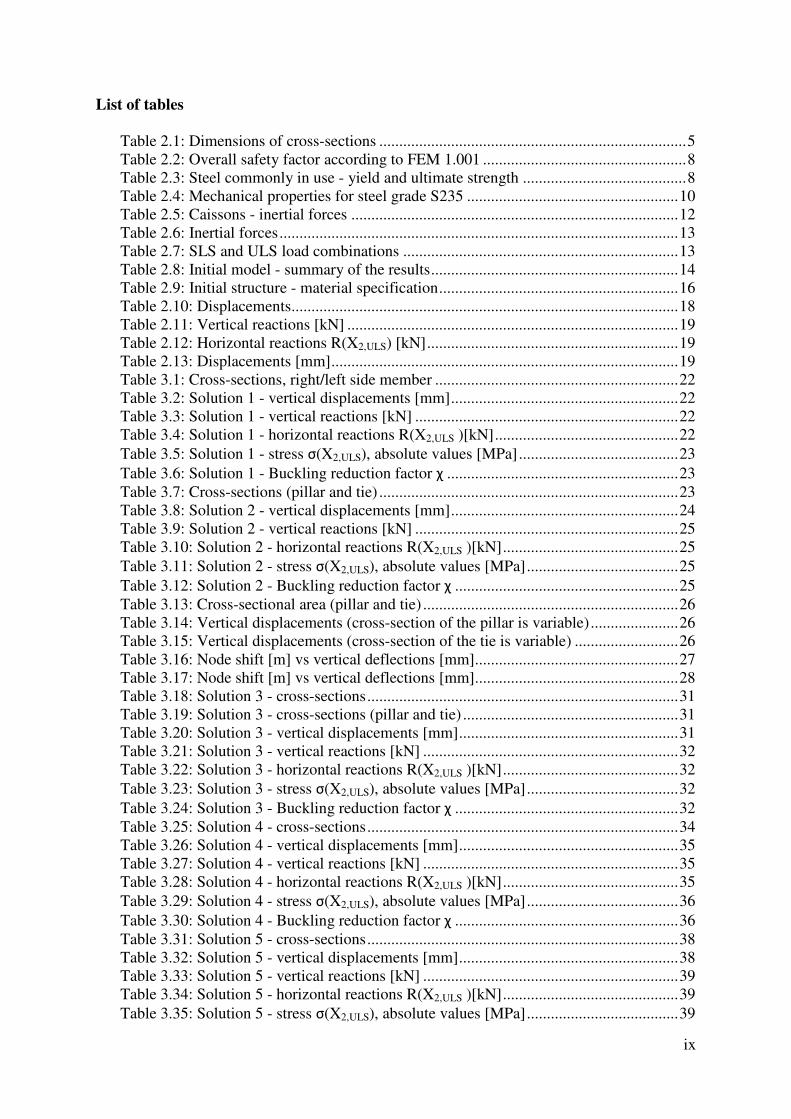
Table 2.1: Dimensions of cross-sections ............................................................................. 5
Table 2.2: Overall safety factor according to FEM 1.001 ................................................... 8
Table 2.3: Steel commonly in use - yield and ultimate strength ......................................... 8
Table 2.4: Mechanical properties for steel grade S235 ..................................................... 10
Table 2.5: Caissons - inertial forces .................................................................................. 12
Table 2.6: Inertial forces .................................................................................................... 13
Table 2.7: SLS and ULS load combinations ..................................................................... 13
Table 2.8: Initial model - summary of the results .............................................................. 14
Table 2.9: Initial structure - material specification ............................................................ 16
Table 2.10: Displacements ................................................................................................. 18
Table 2.11: Vertical reactions [kN] ................................................................................... 19
Table 2.12: Horizontal reactions R(X2,ULS) [kN] ............................................................... 19
Table 2.13: Displacements [mm] ....................................................................................... 19
Table 3.1: Cross-sections, right/left side member ............................................................. 22
Table 3.2: Solution 1 - vertical displacements [mm] ......................................................... 22
Table 3.3: Solution 1 - vertical reactions [kN] .................................................................. 22
Table 3.4: Solution 1 - horizontal reactions R(X2,ULS )[kN] .............................................. 22
Table 3.5: Solution 1 - stress σ(X2,ULS), absolute values [MPa] ........................................ 23
Table 3.6: Solution 1 - Buckling reduction factor χ .......................................................... 23
Table 3.7: Cross-sections (pillar and tie) ........................................................................... 23
Table 3.8: Solution 2 - vertical displacements [mm] ......................................................... 24
Table 3.9: Solution 2 - vertical reactions [kN] .................................................................. 25
Table 3.10: Solution 2 - horizontal reactions R(X2,ULS )[kN] ............................................ 25
Table 3.11: Solution 2 - stress σ(X2,ULS), absolute values [MPa] ...................................... 25
Table 3.12: Solution 2 - Buckling reduction factor χ ........................................................ 25
Table 3.13: Cross-sectional area (pillar and tie) ................................................................ 26
Table 3.14: Vertical displacements (cross-section of the pillar is variable) ...................... 26
Table 3.15: Vertical displacements (cross-section of the tie is variable) .......................... 26
Table 3.16: Node shift [m] vs vertical deflections [mm] ................................................... 27
Table 3.17: Node shift [m] vs vertical deflections [mm] ................................................... 28
Table 3.18: Solution 3 - cross-sections .............................................................................. 31
Table 3.19: Solution 3 - cross-sections (pillar and tie) ...................................................... 31
Table 3.20: Solution 3 - vertical displacements [mm] ....................................................... 31
Table 3.21: Solution 3 - vertical reactions [kN] ................................................................ 32
Table 3.22: Solution 3 - horizontal reactions R(X2,ULS )[kN] ............................................ 32
Table 3.23: Solution 3 - stress σ(X2,ULS), absolute values [MPa] ...................................... 32
Table 3.24: Solution 3 - Buckling reduction factor χ ........................................................ 32
Table 3.25: Solution 4 - cross-sections .............................................................................. 34
Table 3.26: Solution 4 - vertical displacements [mm] ....................................................... 35
Table 3.27: Solution 4 - vertical reactions [kN] ................................................................ 35
Table 3.28: Solution 4 - horizontal reactions R(X2,ULS )[kN] ............................................ 35
Table 3.29: Solution 4 - stress σ(X2,ULS), absolute values [MPa] ...................................... 36
Table 3.30: Solution 4 - Buckling reduction factor χ ........................................................ 36
Table 3.31: Solution 5 - cross-sections .............................................................................. 38
Table 3.32: Solution 5 - vertical displacements [mm] ....................................................... 38
Table 3.33: Solution 5 - vertical reactions [kN] ................................................................ 39
Table 3.34: Solution 5 - horizontal reactions R(X2,ULS )[kN] ............................................ 39
Table 3.35: Solution 5 - stress σ(X2,ULS), absolute values [MPa] ...................................... 39

x
Table 3.36: Solution 5 - Buckling reduction factor χ ........................................................ 39
Table 3.37: Solution 6 - vertical displacements [mm] ....................................................... 42
Table 3.38: Solution 6 - vertical reactions [kN] ................................................................ 42
Table 3.39: Solution 6 - horizontal reactions R(X2,ULS )[kN] ............................................ 43
Table 3.40: Solution 6 - stress σ(X2,ULS), absolute values [MPa] ...................................... 43
Table 3.41: Solution 6 - Buckling reduction factor χ ........................................................ 43
Table 3.42: Solution 6 - influence of the modeling approach on the displacements ......... 44
Table 3.43 Solution 6 - influence of the coupling on the displacements ........................... 44
Table 3.44: Solution 7 - vertical displacements [mm] ....................................................... 46
Table 3.45: Solution 7 - vertical reactions [kN] ................................................................ 46
Table 3.46: Solution 7 - horizontal reactions R(X2,ULS )[kN] ............................................ 46
Table 3.47: Solution 7 - stress σ(X2,ULS), absolute values [MPa] ...................................... 46
Table 3.48: Solution 7 - Buckling reduction factor χ ........................................................ 47
Table 3.49: Solution 7 - influence of the diagonal next to the support on the displacements .................................................................... 47
Table 3.50: Solution 7 - influence of the diagonals next to the support and at the intersections on the displacements ............................. 48
Table 3.51: Solution 8 - vertical displacements [mm] ....................................................... 49
Table 3.52: Solution 8 - vertical reactions [kN] ................................................................ 49
Table 3.53: Solution 8 - horizontal reactions R(X2,ULS )[kN] ............................................ 49
Table 3.54: Solution 8 - stress σ(X2,ULS), absolute values [MPa] ...................................... 49
Table 3.55: Solution 8 - influence of the coupling on the displacements .......................... 50
Table 3.56: Vertical displacements [mm] - overall comparison ........................................ 51
Table 3.57: Vertical reactions and weight of the structure - overall comparison .............. 51
Table 3.58: Horizontal reactions R(X2,ULS )[kN] - overall comparison ............................. 52
Table 3.59: Torque acting on the runway beam T(X2,ULS )[kNm] - overall comparison .. 52
Table 3.60: Benefits and drawbacks - summary ................................................................ 52
Table 3.61: Group A of the pre-design solutions .............................................................. 53
Table 3.62: Group B of the pre-design solutions ............................................................... 54
Table 3.63: Group C of the pre-design solutions ............................................................... 54
Table 4.1: Solution 6-1, vertical displacements [mm] ....................................................... 57
Table 4.2: Design of cross-sections - formulas summary .................................................. 58
Table 4.3: Flexural buckling design check- formulas summary ........................................ 59
Table 4.4: Stability of members loaded in bending and axial compression- formulas summary ........................................ 60
Table 4.5: Stability of members loaded in bending and axial compression- formulas summary (simplified) .................... 61
Table 4.6: Influence of the classification on the design checks of joints .......................... 62
Table 4.7: Brace failure formulas applicable for overlap KT joints .................................. 64
Table 4.8: Parametric study - site joints positions ............................................................. 66
Table 4.9: Solution 6-1, summary of the weight (structural members) ............................. 69
Table 4.10: Solution 6-1, summary of the weight (additional items) ................................ 69
Table 4.11: Solution 6-1, summary of the weight (total) .................................................. 70
Table 4.12: Solution 6-1, contribution of parts of the structure to the total weight .......... 70
Table 4.13: Solution 6-2, vertical displacements [mm] ..................................................... 72
Table 4.14: Design of cross-sections (angle in tension) - formulas summary ................... 73
Table 4.15: Bolt shear resistance per shear plane .............................................................. 74
Table 4.16: Site joints (Solution 6-2) ................................................................................ 79
Table 4.17: Solution 6-2, summary of the weight (structural members) ........................... 80
Table 4.18: Solution 6-2, summary of the weight (additional items) ................................ 80

xi
Table 4.19: Solution 6-2, summary of the weight (total) .................................................. 80
Table 4.20: Solution 6-2, contribution of parts of the structure to the total weight .......... 81
Table 4.21: Estimated final weight - comparison .............................................................. 81

1
1. Introduction
This thesis is dedicated to the carriage structure intended to support the induction furnace in the heat treatment of steel strips and it is conducted in collaboration with Drever International. The current solution was developed by the company and consists of a system of mutually perpendicular beams/girders, loaded normal to its plane.
The main objective of this thesis is to improve the structural system and to optimize the transfer carriage structure. Generally speaking, the optimization can be carried out in terms of the weight reduction, simplification of joints and details, manufacturing, transportation, assembling, etc. There is no perfect solution which can satisfy all these criteria, but the parametric study is necessary in order to select a solution that fits the most all these requirements, what will be conducted in this work as well. The content of this thesis is organized in five chapters, as follows: Chapter 2 analyzes the so-called initial solution of the carriage structure which is subject to the optimization. General layout of the structure is presented, methodology and assumptions for the design and results. The results are used as a basis for comparisons with all proposed solutions in the subsequent chapter. Apart from this, standards applicable to cranes are reviewed, as well as the classification of cranes. Chapter 3 deals with proposed solutions at the pre-design stage, showing their layout, parametric studies and results in terms of internal forces, displacements and the estimated weight as well. All these solutions are compared mutually and with the initial solution. Benefits and drawbacks of each solution are reviewed and selection of the solution for the detailed design is conducted here as well. The selected solution is composed of planar trusses made of hollow sections and further will be designed in two versions: - Solution 6-1: Welded solution made completely of hollow sections - Solution 6-2: Bolted solution made of hollow section chords and angles as braces Chapter 4 presents the main methodology used in the design process. Design is conducted through the serviceability limit states and ultimate limit states for both variants of the selected solution. A special care is taken for design of joints, since some cases that occur in this structure are not covered by the codes. After the detailed design stage the weight of the structure is estimated precisely. The estimation shows significant material savings and the fact that the savings were underestimated in the pre-design stage. The computation details are provided in Annex A (for Solution 6-1) and Annex B (for Solution 6-2). Chapter 5 is devoted for the conclusions. It summarizes the material savings and shows the importance of the optimization process.

2. Study of the initial solution
2.1. General layout and dimensions of the structure
The initial solution can be described as a grillage structure, dimensions. It consists of a system of to its plane. The only part of the structure that is out of the horizontal plane are brackets, the purpose to compensate torsion effects. For clear understanding, designation of all parts of the structure is given in Figure 2.1
Figure 2.1: General layout and designation (
Sides of the structure (right/left) and coincides to the project of the equipment that is supported by equipment, this designation is important, production process (galvanizing/annealing) The carriage structure is supported by a pair of rails placed on top of the crane runway beams. The runway beam forms a frame together with columns. The distance between the rails (axisto-axis) is 9 m, what matches with the distancSince the craneway structure is briefly, showing only the data that is in relation with the carriage structure. the runway beam is a welded box section and its shape and dimensions are shown 2.2. The crane carriage assembly is placed on level +9920 what is the position of the top edge of the rail, while the horizontal reactions are transferred to the runway beam at levels +and +8065 what means that the lever arm is 9715horizontal reactions act in opposite directions, on the distance of 1830 mm, the runway beam has to resist significant torsion and that is the reason for selecting while for the columns circular hollow sections are selected and their height is 7630 mm.
he initial solution
General layout and dimensions of the structure
can be described as a grillage structure, in terms of its layout and dimensions. It consists of a system of mutually perpendicular beams/girders, loaded to its plane. The only part of the structure that is out of the horizontal plane are brackets,
compensate torsion effects. For clear understanding, designation of all parts of Figure 2.1.
General layout and designation (source: Drever calculation sheets)
(right/left) are assigned in relation to the view from the operator sideand coincides to the project of the equipment that is supported by the
this designation is important, for instance the fact that steel process (galvanizing/annealing) travels from the right side towards the structure.
s supported by a pair of rails placed on top of the crane runway beams. The runway beam forms a frame together with columns. The distance between the rails (axis
what matches with the distance between the columns (axisSince the craneway structure is beyond the scope of this Master thesis, it will be
the data that is in relation with the carriage structure. a welded box section and its shape and dimensions are shown
The crane carriage assembly is placed on level +9920 what is the position of the top edge of the rail, while the horizontal reactions are transferred to the runway beam at levels +and +8065 what means that the lever arm is 9715-8065=1830 mm. Due to the fact thathorizontal reactions act in opposite directions, on the distance of 1830 mm, the runway beam has to resist significant torsion and that is the reason for selecting a builtwhile for the columns circular hollow sections are selected and their height is 7630 mm.
2
s of its layout and girders, loaded normal
to its plane. The only part of the structure that is out of the horizontal plane are brackets, with compensate torsion effects. For clear understanding, designation of all parts of
Drever calculation sheets)
view from the operator side, the structure. For the steel strip during the
owards the structure.
s supported by a pair of rails placed on top of the crane runway beams. The runway beam forms a frame together with columns. The distance between the rails (axis-
e between the columns (axis-to-axis as well). it will be described
the data that is in relation with the carriage structure. Cross-section of a welded box section and its shape and dimensions are shown in Figure
The crane carriage assembly is placed on level +9920 what is the position of the top edge of the rail, while the horizontal reactions are transferred to the runway beam at levels +9715
Due to the fact that the horizontal reactions act in opposite directions, on the distance of 1830 mm, the runway beam
built-up box section, while for the columns circular hollow sections are selected and their height is 7630 mm.

Figure
The crane carriage assembly is composed of the carriage structure itself plus secondary structural assemblies that are not part of the detailed study, however their weight and acting on them have to be taken into account for the carriage structure ansecondary assemblies are: three floor assemblies (upper floor assembly, carriage floor assembly and lower floor assembly) including their columns, four bogie platform assemblies and several ladders. As an illustration of the structure including2.3 is given. The crane carriage assembly is intended to translate from the park position to the operating position for a distance of 10855 mm.
Figure 2.3: Carriage assembly
Figure 2.2: Runway beam (cross-section)
The crane carriage assembly is composed of the carriage structure itself plus secondary structural assemblies that are not part of the detailed study, however their weight and
have to be taken into account for the carriage structure ansecondary assemblies are: three floor assemblies (upper floor assembly, carriage floor assembly and lower floor assembly) including their columns, four bogie platform assemblies
several ladders. As an illustration of the structure including all sub-The crane carriage assembly is intended to translate from the park position to the
operating position for a distance of 10855 mm.
: Carriage assembly-3D view (source: Drever calculation sheets)
3
The crane carriage assembly is composed of the carriage structure itself plus secondary structural assemblies that are not part of the detailed study, however their weight and loads
have to be taken into account for the carriage structure analysis. The secondary assemblies are: three floor assemblies (upper floor assembly, carriage floor assembly and lower floor assembly) including their columns, four bogie platform assemblies
-assemblies, Figure
The crane carriage assembly is intended to translate from the park position to the
view (source: Drever calculation sheets)

A scheme of the structure showing axes of the structural members is given the elevation is given in Figure 2.4
transfer vertical loading to the craneway structure and allow translation of the carriage. In the longitudinal direction the distance between two bogies is 10465 mm, while the distance between two horizontal bogies 2.4 as well.
Figure 2.4: Carriage structure
Figure
The height of the carriage structure is 1165 mm and in other words, the highest point of the carriage is on level +11210, while the brackets extend on the bottom side mm (to level +8065, what is the position of the bottom rail for Cross-sections selected for the supporting beams, side members and connecting beam are welded built-up box sections with constant height, except for the supporting beams that are tapered, to allow placing of the roller bogies. All abwith constant thickness along the longitudinal axis. The structural members are given in stiffened by means of transverse stiffenersbox, shear buckling of the web etc.
A scheme of the structure showing axes of the structural members is given Figure 2.4. The carriage structure is placed on four roller bogies that to the craneway structure and allow translation of the carriage. In the
longitudinal direction the distance between two bogies is 10465 mm, while the distance horizontal bogies in the same direction is 2535 mm, what is illustrated
: Carriage structure-elevation (source: Drever calculation sheets)
Figure 2.5:Scheme - axes of the structural members
The height of the carriage structure is 1165 mm and in other words, the highest point of the carriage is on level +11210, while the brackets extend on the bottom side mm (to level +8065, what is the position of the bottom rail for the horizontal reactions).
sections selected for the supporting beams, side members and connecting beam are up box sections with constant height, except for the supporting beams that are
tapered, to allow placing of the roller bogies. All above mentioned beams with constant thickness along the longitudinal axis. The cross-section
are given in Table 2.1. It should be mentioned that the beams are stiffened by means of transverse stiffeners (diaphragms), in order to prevent distortion of the box, shear buckling of the web etc.
4
A scheme of the structure showing axes of the structural members is given in Figure 2.5 and is placed on four roller bogies that
to the craneway structure and allow translation of the carriage. In the longitudinal direction the distance between two bogies is 10465 mm, while the distance
is 2535 mm, what is illustrated in Figure
elevation (source: Drever calculation sheets)
The height of the carriage structure is 1165 mm and in other words, the highest point of the carriage is on level +11210, while the brackets extend on the bottom side for a value of 1980
orizontal reactions).
sections selected for the supporting beams, side members and connecting beam are up box sections with constant height, except for the supporting beams that are
ove mentioned beams are made of plates sizes of the main
It should be mentioned that the beams are , in order to prevent distortion of the
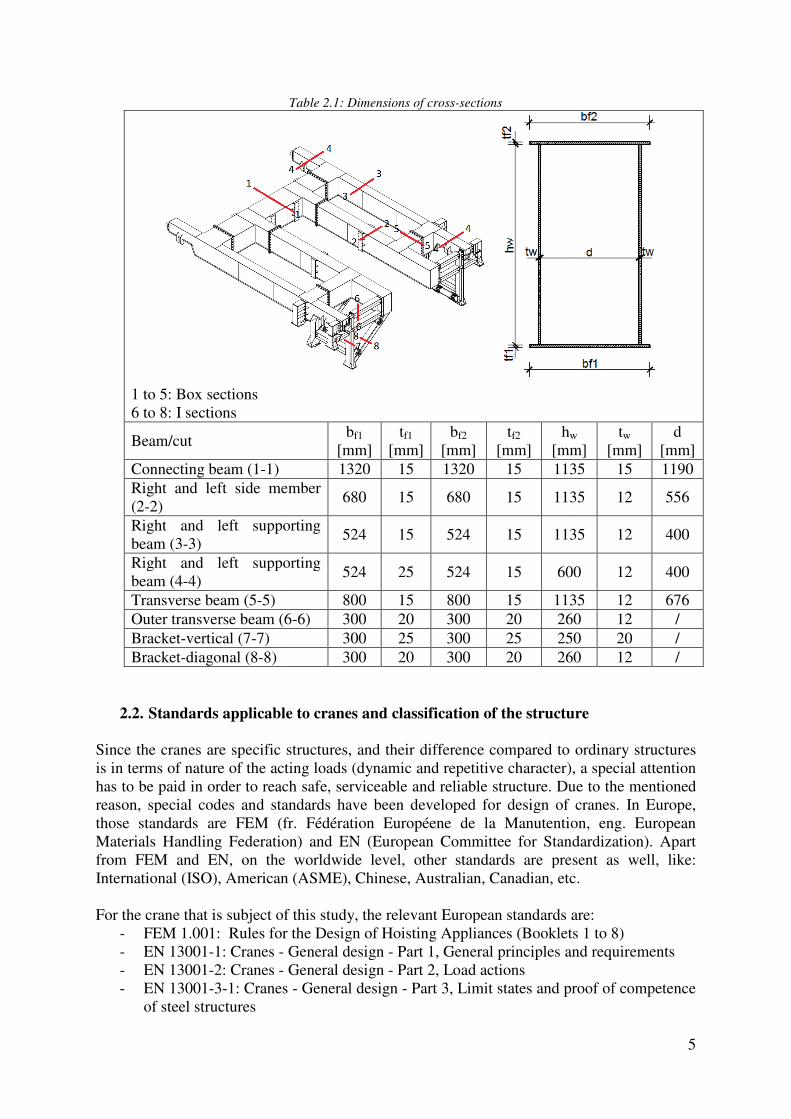
1 to 5: Box sections 6 to 8: I sections
Beam/cut
Connecting beam (1-1) Right and left side member (2-2) Right and left supporting beam (3-3) Right and left supporting beam (4-4) Transverse beam (5-5) Outer transverse beam (6Bracket-vertical (7-7) Bracket-diagonal (8-8)
2.2. Standards applicable to cranes
Since the cranes are specific structures, is in terms of nature of the acting loads (dynamic and repetitive character), a special attention has to be paid in order to reach safe, serviceable and reliable structure. Due to the mentioned reason, special codes and standards have been developed for design of cranesthose standards are FEM (fr. Materials Handling Federationfrom FEM and EN, on the worldwide level, other standards are present as well, like: International (ISO), American (ASME), Chinese, Australian, Canadian, etc. For the crane that is subject of this study, the relevant European standards are:
- FEM 1.001: Rules for the Design of Hoisting Appliances (Booklets 1 to 8)- EN 13001-1: Cranes - - EN 13001-2: Cranes - - EN 13001-3-1: Cranes
of steel structures
Table 2.1: Dimensions of cross-sections
bf1
[mm] tf1
[mm] bf2
[mm] tf2
[mm] hw
[mm] 1320 15 1320 15 1135
Right and left side member 680 15 680 15 1135
Right and left supporting 524 15 524 15 1135
Right and left supporting 524 25 524 15 600
800 15 800 15 1135Outer transverse beam (6-6) 300 20 300 20 260
300 25 300 25 250300 20 300 20 260
Standards applicable to cranes and classification of the structure
Since the cranes are specific structures, and their difference compared to ordinary structures acting loads (dynamic and repetitive character), a special attention
reach safe, serviceable and reliable structure. Due to the mentioned reason, special codes and standards have been developed for design of cranes
fr. Fédération Européene de la Manutentioning Federation) and EN (European Committee for Standardization
the worldwide level, other standards are present as well, like: , American (ASME), Chinese, Australian, Canadian, etc.
ect of this study, the relevant European standards are: FEM 1.001: Rules for the Design of Hoisting Appliances (Booklets 1 to 8)
General design - Part 1, General principles and requirements General design - Part 2, Load actions
1: Cranes - General design - Part 3, Limit states and proof of competence
5
w
[mm] tw
[mm] d
[mm] 1135 15 1190
1135 12 556
1135 12 400
600 12 400
1135 12 676 260 12 / 250 20 / 260 12 /
lassification of the structure
and their difference compared to ordinary structures acting loads (dynamic and repetitive character), a special attention
reach safe, serviceable and reliable structure. Due to the mentioned reason, special codes and standards have been developed for design of cranes. In Europe,
Fédération Européene de la Manutention, eng. European European Committee for Standardization). Apart
the worldwide level, other standards are present as well, like: , American (ASME), Chinese, Australian, Canadian, etc.
ect of this study, the relevant European standards are: FEM 1.001: Rules for the Design of Hoisting Appliances (Booklets 1 to 8)
Part 1, General principles and requirements
Part 3, Limit states and proof of competence

6
The initial solution was designed according to FEM 1.001. In order to obtain comparable results of all other solutions that will be analyzed later in this work to the initial solution and upon the suggestion of the DREVER representatives, FEM 1.001 will be used further for the classification, loads and combination of loads, while the resistance of cross-sections, members and joints will be calculated according to the relevant parts of Eurocode 3. Since the standard covers a variety of hoisting appliances, which can be utilized in different ways, the code requires that a structure has to be classified, to take into account these differences. Consequently, when a structure is classified the code suggests which design checks should be performed. They are mainly related to the fatigue life and wear of parts of a structure. For instance, the significant difference is present between a crane moving on very high speeds and with a high number of working cycles and a crane of a light utilization. In the first case, the structure is susceptible to the fatigue, while the second structure is not and its design will be governed by the ultimate limit states and serviceability limit states. The amplifying coefficient γc takes into account a probability of exceeding the calculated stress, which results from imperfect methods of calculation and unpredicted events. According to the code, actions on the structure should be multiplied by the coefficient γc and the coefficient itself is dependent on the classification while its value varies from 1.0 to 1.2. According to FEM 1.001, a crane should be classified on three levels:
- the appliance as a whole - the individual mechanisms as a whole - the structural and mechanical components
To classify a structure the code uses two criteria, namely:
- the total duration of use of the item considered - the hook load, loading or stress spectra to which the item is subjected
The total duration of use is divided into ten classes of utilization, designated by the symbols U0 to U9 and dependent on the number of cycles nmax. U0 corresponds to nmax≤16000 cycles, while U9 corresponds to nmax≤4000000 cycles and they are summarized in Table T.2.1.2.2. of FEM 1.001, Booklet 2. There are four spectrum classes, Q1 to Q4, which are dependent on the spectrum factor kp that is indeed a distribution function with possible values from 0 to 1. The relation between kp and the spectrum classes is given in Table T.2.1.2.3. of FEM 1.001, Booklet 2. Finally, the appliance as a whole is classified by combining the class of utilization and load spectrum class, resulting in eight possible classes, A1 to A8. The scheme for combining U and Q values is provided in Table T.2.1.2.4. of FEM 1.001, Booklet 2. On the other hand, EN 13001-1 does not combine the total number of cycles and the load spectra in an unique class of the appliance as a whole. Four criteria are specified by EN13001-1 for the classification and accordingly, for each criteria a different class is assigned, namely:
- the total number of working cycles during the specified design life (class U0 to U9) - the average distances (class Dh0 to Dh9 for hoisting, Dt0 to Dt9 for traversing, Dc0 to
Dc9 for travelling and Da0 to Da5 for angular displacement) - the relative frequencies of loads to be handled-load spectra (class Q0 to Q5) - the average number of accelerations per movement (class P0 to P3)
7
It should be mentioned that EN 13001-1 omits the classes of mechanisms (in FEM 1.001 designated as M-classes) and instead uses criteria for average distances and average number of accelerations per movement. The carriage structure that is subject of the study is intended to support two caissons. The caissons are imposed on the structure by an external device such a mobile crane. The structure itself does not have any hoisting device or traverse trolley, what means that there is no need for the classification of mechanisms, while the classification of the appliance as a whole is already described in detail. For the proof of competence of a structure, generally, there are two well-known methods: the limit state method and the allowable stress method. At the time when FEM 1.001 was developed (the first edition in 1962, the second in 1970 and the third in 1998) the allowable stress method was commonly used by engineers and suggested by codes. FEM 1.001 uses the allowable stress method for the proof of competence, however the limit state method is mentioned in Booklet 9 (included in the 3rd revision in 1998) when EN 13001 still had been under the development. According to EN 13001 the limit state method is applicable without any restriction though the allowable stress method is allowed for cranes or portions of cranes where all masses act only unfavorable and with a linear relationship between load actions and load effect. Here, the allowable stress method is considered as a special case of the limit state method, where the same numerical value is assigned for all partial safety factors. For instance, in the case of overhead crane and portal crane without cantilevers or in other words, for all cranes which lift/support loads inside the area bounded by the supporting substructure. This is the case for the carriage analyzed in this Master Thesis as well. The allowable stress method is not allowed for tower cranes, because a counterweight equilibrates the imposed loading, and acts favorable, what means that they should be multiplied by different partial safety factors. The proof of competence, using the limit state method, according to EN 13001 should be checked as follows:
γn·Σ(γp·fi)≤Rk
γm
where: γn is the risk coefficient, where applicable γp is the partial safety factor applied to individual load according to the load combination fi is the characteristic load i on the element including dynamic factors Rk is the characteristic resistance of the material, particular element or connection γm is the resistance coefficient while for the allowable stress method, the proof of competence according to EN 13001 should be checked as:
Σ fi≤�� = Rk
γf·γn
where: fi is the characteristic load i on the element including dynamic factors Rk is the characteristic resistance of the material, particular element or connection γf is the overall safety factor applied to the specified strength according to the load combination under consideration

8
γn is the risk coefficient, where applicable σa is the allowable stress FEM 1.001 uses the allowable stress method as it was already mentioned and only the designation is different compared to EN 13001. The allowable stress and overall safety factor (designated in FEM 1.001 as σa and νE respectively) are defined by the code depending on the stress state in a member and the applied load case. The code takes into account the mechanical characteristics of used steel. For case of steel where the ratio between the yield strength and the ultimate tensile strength is lower than 0.7 and for members subjected to simple tension or compression, the values of νE are provided in Table 2.2. Load cases I-III given in the code will be discussed later.
Table 2.2: Overall safety factor according to FEM 1.001
Load case Case I Case II Case III νE 1.5 1.33 1.1
Steel commonly in use, like S235, S275 and S355 produced in accordance with EN 10025-2 (non-alloy structural steels), EN 10021-1 (hot finished structural hollow sections of non-alloy and fine grain steels) and EN 10219-1 (cold formed welded structural hollow sections of non-alloy and fine grain steels) fulfill the condition fy/fu<0.7. As an illustration, Table 2.3 is given.
Table 2.3: Steel commonly in use - yield and ultimate strength
Steel grade fy [N/mm2] fu [N/mm2] fy/fu S235 235 360 0.653 S275 275 430 0.640 S355 355 510 0.696
In the case of steels with high elastic limit (fy/fu>0.7), the use of the coefficient νE does not provide a sufficient level of safety, and a guidance for the calculation of the allowable stress is given in FEM 1.001 paragraph 3.2.1.1. 2). For shear, the allowable stress is τa=σa/3
0.5 (σa is the allowable tensile stress), while for a member subjected to combined loads, Von-Misses criterion is used and it is defined by the following formula: σx
2+ σy2-σx σy+3 τxy
2< σa. Since the load cases are in relation with the proof of competence and the fact that this sub-chapter is dedicated to design codes, loads and load cases that have to be taken into account according to FEM 1.001 will be summarized here, while the application of the rules on the carriage structure is provided in sub-chapter 2.4. Loads entering into the design of structures, specified by the code are:
- The principal loads exerted on the structure of the appliance, assumed to be stationary, in the most unfavorable state of loading
- Loads due to vertical motions - Loads due to horizontal motions - Loads due to climatic effects
The principal loads include the loads due to the dead weight of the components and the loads due to the working load (designated as SG and SL respectively). As regards loads due to vertical motions, they include loads due to hoisting of the working load and loads due to

9
acceleration of the hoisting motion. Loads due to vertical motions are not relevant for the carriage structure under the study since it is not equipped by any hoisting device. Loads due to horizontal motion are the inertia effects due to acceleration, the effects of centrifugal force, transverse horizontal reactions resulting from rolling action and buffer effects. Wind load, snow load and temperature variations belong to the climatic effects and they are not relevant for the carriage structure due to the fact that the structure is located inside a building. The code specifies three different load cases to be considered in the calculations, namely:
- Case I: Appliance working without wind - Case II: Appliance working with wind - Case III: Appliance subjected to exceptional loadings
A relation could be made now between the safety factor νE and the load cases. As long as the probability of occurrence is lower, the safety factor is lower. For instance, for Case III the value is 1.1. Similar philosophy is used in Eurocode 0 through the limit state method and partial safety factors for loading, where the combination of loads in persistent and transient design situations for ULS is 1.35Gkj,sup+1.5Qkj,inf+1.5ψ0,i5Qk,i while the combination in accidental and seismic design situations for ULS is Gkj,sup+Ad+(ψ1,1 or ψ2,1)Qk,1+ψ2,iQk,i.
2.3. Calculation assumptions
This sub-chapter is devoted to the calculation assumptions used by DREVER International in design of the initial solution, what is the basis for all further considerations.
- Actions on the carriage are calculated according to FEM 1.001. - Combinations of actions are calculated according to FEM 1.001. - Cross-section design checks are performed in accordance with FEM 1.001, while the
joints are designed in accordance with Eurocode 3. In design of the optimized solution (chapter 4), Eurocode 3 is used for cross-section/member checks as well as for design of joints.
- The structure is exposed to the maximum environmental temperature of 80°C and it is free to expand.
- At the temperature of 80°C the mechanical properties are not altered. Hence, together with the previous assumption leads that the effect of the temperature can be neglected.
- The corrosion effect is not taken into account. - The structure is located inside a building what means that the climate effects are not
relevant. - The seismic action is not considered. - The number of stress cycles during the design working life of the structure is 20000,
thus the fatigue assessment is not necessary. - The maximum transfer speed is 4 m/min (an elevation and the lateral translation are
not present). - Four roller bogies transfer the vertical loading to the runway structure and allow the
translational movement. Each roller bogie consists of two rollers and each is equipped by an engine.
- The caissons cannot swing since they are fixed to the structure by the supporting plates, while the forces coming from the accelerations/decelerations are taken into account, acting in the center of gravity of the caissons
- The deflection limit is l/1250 and the value is 7.17 mm - Steel grade S235 is used for the structure and the mechanical properties are given in
Table 2.4.

Table 2
Yield strengthUltimate tensile strengthModulus of elasticityShear modulusPoisson's coefficient
Classification of the structure was discussed in subthe carriage structure in accordance with FEM 1.001. The number of stress cycles during the design working life of the strleads to the utilization class during its use what results in the spectrum factor kclass is Q4. By combining these values, the applia Respecting the classification, the amplifying coefficient is does not have any hoisting device, the dynamic coefficient has to be taken into account with is minimum value, hence ψ=1.1
2.4. Loads and combinations of loads
2.4.1. Dead weight (S
It includes weight of the carriage structure itself and weight of the secondary structural assemblies, for example the platforms. For the standard acceleration due to gravity a value of 9.81 m/ssteel is ρ=7850 kg/m2. In analysis of the initial solution, weight of the whole carriage assembly was taken automatically by the softwareInternational. The platform assemblies are not within thweight will be applied to the carriage structurefollowing the scheme given in
Figure 2.6: Loading from th
2.4: Mechanical properties for steel grade S235
Yield strength fy=235 N/mm2 Ultimate tensile strength fu=360 N/mm2 Modulus of elasticity E=210 000 N/mm2 Shear modulus G=81 000 N/mm2 Poisson's coefficient ν=0.3
Classification of the structure was discussed in sub-chapter 2.2 and here it will be applied to the carriage structure in accordance with FEM 1.001.
The number of stress cycles during the design working life of the structure is 20000 what leads to the utilization class U1. The structure is subjected to 100% of the imposed load during its use what results in the spectrum factor kp equal to 1 and consequently the spectrum
By combining these values, the appliance as a whole is classified as
Respecting the classification, the amplifying coefficient is γc=1.05. Even though the structure does not have any hoisting device, the dynamic coefficient has to be taken into account with
ψ=1.15.
Loads and combinations of loads
Dead weight (SG)
It includes weight of the carriage structure itself and weight of the secondary structural assemblies, for example the platforms.
For the standard acceleration due to gravity a value of 9.81 m/s2 is taken while the density of In analysis of the initial solution, weight of the whole carriage
taken automatically by the software in the model created by DREVER International. The platform assemblies are not within the scope of the Thesis
to the carriage structure at positions of their columns n Figure 2.6.
: Loading from the platforms applied on the carriage structure
10
chapter 2.2 and here it will be applied to
ucture is 20000 what The structure is subjected to 100% of the imposed load
equal to 1 and consequently the spectrum nce as a whole is classified as A3.
=1.05. Even though the structure does not have any hoisting device, the dynamic coefficient has to be taken into account with
It includes weight of the carriage structure itself and weight of the secondary structural
is taken while the density of In analysis of the initial solution, weight of the whole carriage
in the model created by DREVER e scope of the Thesis, therefore their
at positions of their columns in further models
e platforms applied on the carriage structure
2.4.2. Working loads (S
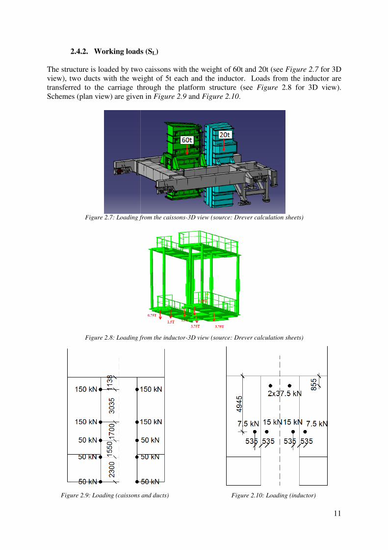
The structure is loaded by two caissons with the weight of 60t and 20tview), two ducts with the weight of 5t each and transferred to the carriage through the platform structureSchemes (plan view) are given
Figure 2.7: Loading from t
Figure 2.8: Loading from the inductor
Figure 2.9: Loading (caissons and ducts)
Working loads (SL)
The structure is loaded by two caissons with the weight of 60t and 20t (see , two ducts with the weight of 5t each and the inductor. Loads from the inductor are
transferred to the carriage through the platform structure (see Figure given in Figure 2.9 and Figure 2.10.
: Loading from the caissons-3D view (source: Drever calculation sheets)
: Loading from the inductor-3D view (source: Drever calculation sheets)
: Loading (caissons and ducts)
Figure 2.10: Loading (inductor)
11
(see Figure 2.7 for 3D Loads from the inductor are
2.8 for 3D view).
3D view (source: Drever calculation sheets)
3D view (source: Drever calculation sheets)
: Loading (inductor)

2.4.3. Loads due to horizontal
The structure is intended to move with a speed of 4 m/minmoderate and high speed appliances (normal application) the corresponding acceleration of 0.5 m/s2 should be taken into account. The acceleration is applied on the whole carriage, on the caissons at their center of gravity, on On the caisson, the inertial force I acts at its center of gravity and when we move the force on the top edge of the beam, we have an additional moment M, that is further resolved to a couple of forces V. Finally, thestructure. Step-by-step procedure is given platforms, ducts and inductor see
Figure 2.11: Inertial forces due to horizontal motions: step
m [kg]
Caisson 60t 60000 30000Caisson 20t 20000 10000
where I is the inertial force (I=m·a) e is the distance between center of gravity of the caisson and the top edge of the beamd is the distance between the supporting plates V1 is the vertical force acting on one beam (V
Loads due to horizontal motions
The structure is intended to move with a speed of 4 m/min. According to FEM 1.001, for moderate and high speed appliances (normal application) the corresponding acceleration of
should be taken into account. The acceleration is applied on the whole carriage, on the caissons at their center of gravity, on the ducts, platforms and inductor.
On the caisson, the inertial force I acts at its center of gravity and when we move the force on the top edge of the beam, we have an additional moment M, that is further resolved to a couple of forces V. Finally, the horizontal force I and the vertical forces V act on the
step procedure is given in Figure 2.11, and the values in platforms, ducts and inductor see Table 2.6.
: Inertial forces due to horizontal motions: step-by-step procedure
Table 2.5: Caissons - inertial forces
I [N]
e [m]
M [Nm]
d [m]
V [N]
30000 0.361 10830 3.035 3568.4 1784.210000 0.4 4000 1.55 2580.6 1290.3
e is the distance between center of gravity of the caisson and the top edge of the beamd is the distance between the supporting plates
is the vertical force acting on one beam (V1=V/2)
12
. According to FEM 1.001, for moderate and high speed appliances (normal application) the corresponding acceleration of
should be taken into account. The acceleration is applied on the whole carriage, on , platforms and inductor.
On the caisson, the inertial force I acts at its center of gravity and when we move the force on the top edge of the beam, we have an additional moment M, that is further resolved to a
horizontal force I and the vertical forces V act on the , and the values in Table 2.5. For the
step procedure
V1 [N]
V1 [kN]
1784.2 1.78 1290.3 1.29
e is the distance between center of gravity of the caisson and the top edge of the beam

13
Table 2.6: Inertial forces
m [kg]
I [N]
I [kN]
Duct 5t (per duct) 5000 2500 2.5 Platform (per column) 1836 918 0.92 Carriage structure 28062 14031 14.03 Inductor 12000 6000 6
The inertial forces of the carriage structure itself are applied as uniformly distributed loading along the structural members.
Buffer effects on the structure are neglected according to FEM 1.001 because the horizontal speed of the appliance is lower than 0.7 m/s. The structure does not slew, hence the effects of centrifugal force does not have to be taken into account. These effects are relevant only for jib cranes. Transverse reactions due to rolling action are only important for the runway structure which is not within the scope of this Thesis.
2.4.4. Other actions
Loads due to vertical motions are not present as the structure does not have any hoisting device. Loads due to climatic effects are not relevant, because the structure is located inside a building. According to FEM 1.001, for gangways and platforms intended only for access of personnel the load (SP) of 1.5 kN/m2 should be taken into account, but these loads are not to be used in the calculations for girders (only for design of platform structures which are out of the scope of the Thesis).
2.4.5. Combinations of loads
As it was already mentioned in sub-chapter 2.2, the code specifies three load cases to be considered in the calculations. Case II and Case III do not have to be considered as long as the structure is not exposed to wind actions neither to exceptional actions. Possible combinations of loads that are taken into account (corresponding to Case I) are indicated in Table 2.7.
Table 2.7: SLS and ULS load combinations
SLS ULS X1,SLS=γc·SG X1,ULS=1.5·X1 X2,SLS=γc·(SG+ψ·SL) X2,ULS=1.5·X2 X3,SLS= γc·(SG+ψ·SL+SHx+) X3,ULS=1.5·X3 X4,SLS= γc·(SG+ψ·SL+SHx-) X4,ULS=1.5·X4 X5,SLS=γc·(SG+ψ·SP) X5,ULS=1.5·X5
As it is obvious from Table 2.7, the unique safety coefficient with a value of 1.5 was used for all loads in the calculations of the initial model performed by DREVER International and the same will be used for the all further solutions that will be analyzed upon the agreement with the DREVER representatives. This approach is given in FEM 1.001 and allowed for the use by EN 13001 for the case of bridge cranes, what is explained in detail in sub-chapter 2.2.

Load combinations X3 and X4
that the inertial force SHx acts in opposite directionLoad combination X5 is relevant only for the platforms which will not be analyzed in further proposed solutions.
2.5. Results
Table 2.8 is an overview of the results taken from the calculation sheets done by DREVER International.
Table
Load combination
X1 X2
X3 and X4 It should be mentioned that the stresses given in and they are based on the characteristic values of acting loads, included through the allowable stressnominal stresses were limited to 100 MPa (loads) by the request of the customer, while the l The local stress resulting from load combinations Xwhat means that the limiting value was exceeded in a point.located at the position where the crossbeam, close to the space reserved for the roller bogie). singularities of the finite elements model. Sivalues in this zone are less than 156.66 MPa, this was considered as acceptable by the designer. A graphical interpretation of that zone is given
Figure 2.12: Local stresses (Von Mises) for load combination X
4 are basically the same and the only difference acts in opposite directions, dependent on the direction of motion.
is relevant only for the platforms which will not be analyzed in
is an overview of the results taken from the calculation sheets done by DREVER
Table 2.8: Initial model - summary of the results
Local stress [MPa]
Nominal stress [MPa]
Deflec[mm]
69.17 <100 2.11155.9 <100 7.33170.8 <100 7.33
It should be mentioned that the stresses given in Table 2.8 are Von-Misses equivalent stresses based on the characteristic values of acting loads, hence the safety coefficient is
included through the allowable stress value, which is in this case 235/1.5=156.66 MPa. nominal stresses were limited to 100 MPa (resulting from the characteristic values of acting
by the request of the customer, while the local stresses were limited to 156.66 MPa.
The local stress resulting from load combinations X3 and X4 has a peak value of 170.8 MPa, he limiting value was exceeded in a point. The above-mentioned stress is
located at the position where the cross-section is changing its height (right/left supporting beam, close to the space reserved for the roller bogie). It may appear
s of the finite elements model. Since the stress is very localized and all other values in this zone are less than 156.66 MPa, this was considered as acceptable by the
A graphical interpretation of that zone is given in Figure 2.12.
: Local stresses (Von Mises) for load combination X3/X4 (source: Drever caculation sheets)
14
are basically the same and the only difference between them is , dependent on the direction of motion.
is relevant only for the platforms which will not be analyzed in the
is an overview of the results taken from the calculation sheets done by DREVER
Deflections [mm] 2.11 7.33 7.33
Misses equivalent stresses safety coefficient is
value, which is in this case 235/1.5=156.66 MPa. The resulting from the characteristic values of acting
ocal stresses were limited to 156.66 MPa.
has a peak value of 170.8 MPa, mentioned stress is
section is changing its height (right/left supporting appear as a result of
nce the stress is very localized and all other values in this zone are less than 156.66 MPa, this was considered as acceptable by the
(source: Drever caculation sheets)
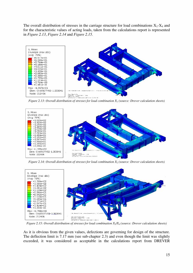
The overall distribution of stresses in the for the characteristic values of acting loads, in Figure 2.13, Figure 2.14 and
Figure 2.13: Overall distribution of stresses for load combination X
Figure 2.14: Overall distribution of stresses for load combination X
Figure 2.15: Overall distribution of stresses for
As it is obvious from the given values, defections are governing for design of the structure. The deflection limit is 7.17 mm (see subexceeded, it was considered as acceptable in the calculations report from DREVER
The overall distribution of stresses in the carriage structure for load combinations Xfor the characteristic values of acting loads, taken from the calculations report is represented
and Figure 2.15.
: Overall distribution of stresses for load combination X1 (source: Drever calculation sheets)
: Overall distribution of stresses for load combination X2 (source: Drever calculation sheets)
: Overall distribution of stresses for load combination X3/X4 (source: Drever calculation sheets)
As it is obvious from the given values, defections are governing for design of the structure. The deflection limit is 7.17 mm (see sub-chapter 2.3) and even though the limit was slightly
it was considered as acceptable in the calculations report from DREVER
15
for load combinations X1-X4 and from the calculations report is represented
(source: Drever calculation sheets)
(source: Drever calculation sheets)
(source: Drever calculation sheets)
As it is obvious from the given values, defections are governing for design of the structure. chapter 2.3) and even though the limit was slightly
it was considered as acceptable in the calculations report from DREVER
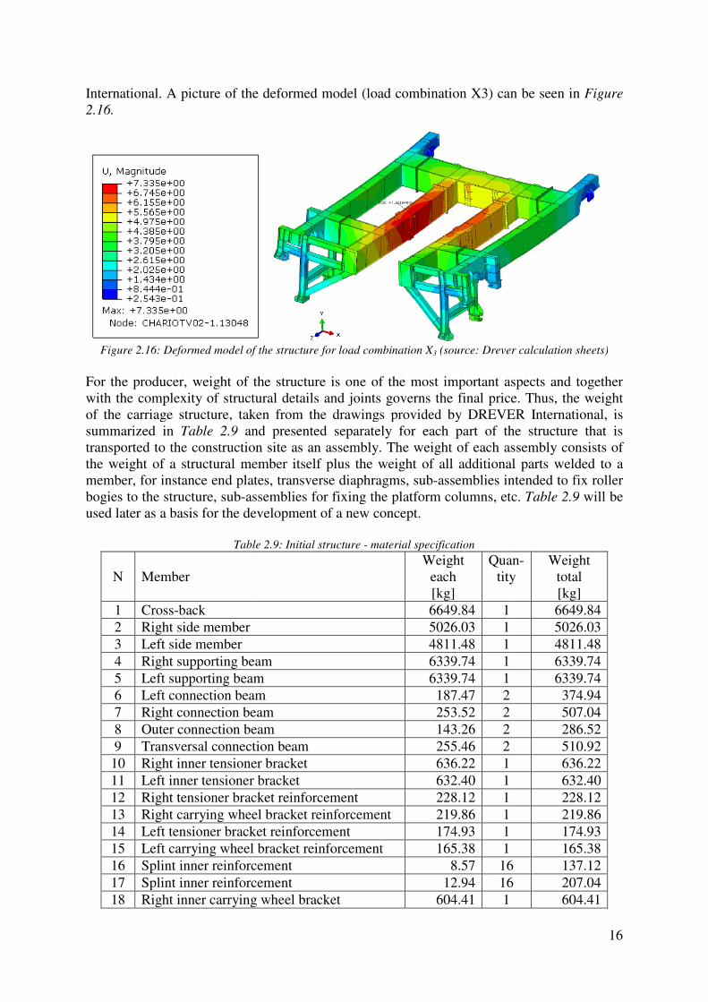
International. A picture of the deformed model 2.16.
Figure 2.16: Deformed model of the s
For the producer, weight of the structure is one of the most important aspects with the complexity of structural details of the carriage structure, taken from the drawings provided by DREVER International, is summarized in Table 2.9 and presented separately for each part of the structure that is transported to the construction the weight of a structural member itself plus the weight of all additional parts welded to a member, for instance end plates, transverse diaphragms, subbogies to the structure, sub-assemblies for fixing the used later as a basis for the development of a new concept.
Table
N Member
1 Cross-back 2 Right side member 3 Left side member 4 Right supporting beam5 Left supporting beam6 Left connection beam7 Right connection beam8 Outer connection beam9 Transversal connection beam
10 Right inner tensioner bracket11 Left inner tensioner bracket12 Right tensioner bracket 13 Right carrying wheel bracket reinforcement14 Left tensioner bracket reinforcement15 Left carrying wheel bracket reinforcement16 Splint inner reinforcement17 Splint inner reinforcement18 Right inner carrying wheel bracket
A picture of the deformed model (load combination X3) can be seen
: Deformed model of the structure for load combination X3 (source: Drever calculation sheets)
For the producer, weight of the structure is one of the most important aspects with the complexity of structural details and joints governs the final price. of the carriage structure, taken from the drawings provided by DREVER International, is
and presented separately for each part of the structure that is transported to the construction site as an assembly. The weight of each assemblthe weight of a structural member itself plus the weight of all additional parts welded to a member, for instance end plates, transverse diaphragms, sub-assemblies intended to fix roller
assemblies for fixing the platform columns, etc. used later as a basis for the development of a new concept.
Table 2.9: Initial structure - material specification
Weight each [kg]
Quantity
6649.84 1 5026.03 1
4811.48 1 Right supporting beam 6339.74 1 Left supporting beam 6339.74 1 Left connection beam 187.47 2
connection beam 253.52 2 Outer connection beam 143.26 2 Transversal connection beam 255.46 2 Right inner tensioner bracket 636.22 1 Left inner tensioner bracket 632.40 1 Right tensioner bracket reinforcement 228.12 1 Right carrying wheel bracket reinforcement 219.86 1 Left tensioner bracket reinforcement 174.93 1 Left carrying wheel bracket reinforcement 165.38 1 Splint inner reinforcement 8.57 16Splint inner reinforcement 12.94 16Right inner carrying wheel bracket 604.41 1
16
can be seen in Figure
(source: Drever calculation sheets)
For the producer, weight of the structure is one of the most important aspects and together price. Thus, the weight
of the carriage structure, taken from the drawings provided by DREVER International, is and presented separately for each part of the structure that is
site as an assembly. The weight of each assembly consists of the weight of a structural member itself plus the weight of all additional parts welded to a
assemblies intended to fix roller platform columns, etc. Table 2.9 will be
Quan- tity
Weight total [kg]
6649.84 5026.03 4811.48 6339.74 6339.74 374.94 507.04 286.52 510.92 636.22 632.40 228.12 219.86 174.93 165.38
16 137.12 16 207.04
604.41
17
19 Left inner carrying wheel bracket 604.41 1 604.41 20 Outer carrying wheel bracket 418.93 2 837.86 21 Outer tensioner bracket 190.57 2 381.14 22 Outer tensioner bracket support 216.64 2 433.28 23 Bridle 79.86 2 159.72
Total 36268.14
2.6. Model for the calibration and development of a new concept
For structural analysis of the carriage structure, a finite element model was created by DREVER International and all above-mentioned results are related to that model. The model was composed of shell finite elements with reduced integration (S4R and S3R) and the average size of elements is 30 mm. The calculations were carried out in Abaqus Standard v6.12. As it is obvious, the model is complex. The structural analysis in the pre-design stage of future solutions has to remain simple, due to the facts that many uncertainties are present before the detailed design stage and a numerical model is constantly subjected to corrections. On the other hand, a numerical model in pre-design has to be accurate enough in order to supply the designer with reliable data and allow him to make proper assumptions for the detailed design. With the aim to obtain the relation between the initial model (done by DREVER) and the pre-design models for new (optimized) solutions of the carriage structure, a finite element model has been created that resembles the model used by DREVER International. It is named Model for the calibration. The model is composed of linear (beam) finite elements, which will be used for all further models as well. A comparison between these two models has to be made here. Deflections are the governing design criterion for this structure, as it can be seen in sub-chapter 2.5 and it is used for the calibration. Consequently the serviceability limit states check will be used for the selection of feasible solutions. As a simplification, the load combinations that will be considered here are only X1 and X2. The following simplifications have been introduced in Model for the calibration:
- Instead of the haunched beam, the right/left side member has been modeled using two different cross-sections with a constant height, one corresponding to the cross-section in the middle of the beam and another one corresponding to the reduced cross-section. Their axes are placed in the same plane, and a sudden change of the cross-section properties are present in a node.
- Outer carrying wheel brackets have been omitted, because they are very stiff and short, and the corresponding node on the side member has been rigidly connected to the horizontal support.
- Working loads (weight of the caissons) have been modeled as point loads, while in the reality and in the initial model, they are introduced through plates of certain dimensions (uniformly distributed load on the area).
Model for the calibration is graphically presented in Figure 2.17.

Figure
A comparison should be made between these two models in terms of the vertical displacements. The values are given in deformed model under loading ireached in the middle of the right side member.
Figure
Load case/combination
SG SL
X1=γc·SG X2=γc·(SG+ψ·SL)
From the results it is obvious that the displacements resulting from the working loads are almost identical (4.33 mm and 4.25 mm), what means that reliable approximation of the behavior of the structure, using liner(beam) finite elements instead of shell finite elements.displacements resulting from the selfmodel includes end plates, transverse diaphragms, subbogies to the structure, sub-assemblies for fixing the platform columns what increases the
Figure 2.17: Model for the calibration - 3D view
A comparison should be made between these two models in terms of the vertical
The values are given in Table 2.10, while a graphical representation of the deformed model under loading is given in Figure 2.18. The maximum displacement is reached in the middle of the right side member.
Figure 2.18: Deformed model of the structure
Table 2.10: Displacements
Initial model z [mm]
Model for the calibrationz [mm]
2.01 1.324.33 4.252.11 1.39
7.335 6.52
From the results it is obvious that the displacements resulting from the working loads are almost identical (4.33 mm and 4.25 mm), what means that Model for the calibration is reliable approximation of the behavior of the structure, although it is simpler using liner(beam) finite elements instead of shell finite elements. The difference in the displacements resulting from the self-weight of the structure is due to the fact that model includes end plates, transverse diaphragms, sub-assemblies intended to fix roller
assemblies for fixing the platform columns what increases the
18
A comparison should be made between these two models in terms of the vertical , while a graphical representation of the
The maximum displacement is
Model for the calibration z [mm]
1.32 4.25 1.39 6.52
From the results it is obvious that the displacements resulting from the working loads are odel for the calibration is
although it is simpler and modeled The difference in the
weight of the structure is due to the fact that the initial semblies intended to fix roller
assemblies for fixing the platform columns what increases the

weight, while Model for the calibration takes into account only the members itself. Due to the above-mentioned facts, the deflection limit that will be used for the estimation of all future models will be 6.85 mm
that have been used in computational models. The vertical reactions resulting from the dead weight R(Sthe estimation of the weight of the structureof shear forces and consequently torque imposed on the runway beams.in Table 2.11, Table 2.12 and the designation
Figure 2.19
The weight of the platforms is 146.88 kN and when it is subtracted from the sum of reactions the resulting value is the weight of the structure itself in the computational 426.88-146.88=279.57 kN
Table
R1 R2 R3
420.65 349.21 188.84 The brackets have strong importance on the overall behavior of the structure since they provide a vertical support to the right/left side member on the motor side of the structure. Their importance can be seen when they are removed and the finite element model is calculated again. Obtained results are given in the model in Figure 2.20.
odel for the calibration takes into account only the weight of
mentioned facts, the deflection limit that will be used for the estimation of 6.85 mm instead of 7.17 mm, in order to compensate
used in computational models.
s resulting from the dead weight R(SG) will be used in further models of the weight of the structure, while the horizontal reactions for the estimation
of shear forces and consequently torque imposed on the runway beams. The values are gand the designation in Figure 2.19.
19: Vertical and horizontal reactions - designation
Table 2.11: Vertical reactions [kN]
R1(SG) 93.93 R2(SG) 100.92 R3(SG) 117.51 R4(SG) 114.09
Σ 426.45
The weight of the platforms is 146.88 kN and when it is subtracted from the sum of reactions the resulting value is the weight of the structure itself in the computational
Table 2.12: Horizontal reactions R(X2,ULS) [kN]
3 R4 R5 R6 188.84 157.72 -452.59 -373.79 -158.00
have strong importance on the overall behavior of the structure since they provide a vertical support to the right/left side member on the motor side of the structure. Their importance can be seen when they are removed and the finite element model is
lated again. Obtained results are given in Table 2.13, while a graphical representation of
Table 2.13: Displacements [mm]
z(SG) 4.33 z(SL) 18.97 z(X1) 4.54 z(X2) 27.5
19
weight of structural
mentioned facts, the deflection limit that will be used for the estimation of , in order to compensate simplifications
in further models for horizontal reactions for the estimation
The values are given
The weight of the platforms is 146.88 kN and when it is subtracted from the sum of reactions model.
R7 R8 158.00 -134.24
have strong importance on the overall behavior of the structure since they provide a vertical support to the right/left side member on the motor side of the structure. Their importance can be seen when they are removed and the finite element model is
, while a graphical representation of

Without the brackets, the maximum displacement is 27.5 mm, what is almost four times more than the allowed value.
Figure
3. Pre-design of proposed solutions
The aim of this chapter is to propose solutions for the improvement of the initial solution on the pre-design level. Proposed solutions will be studied parametrically in order to select the best solution to be studied in detail. Generally speaking, a structure can be optimized in such a way to:
- Reduce weight of the structure,- Simplify structural joints and details,- Reduce the number of specific parts/assemblies (rollers, bogies, etc.),- Increase the amount of work to be done in a workshop and therefore to
amount of work on a construction site,- Intend to perform welding in a workshop rather than on a site,- Increase the size of parts to be transported up to the limits specified by the traffic
regulations, - Use commercial open or hollow sections rath- Intend to have as much as possible uniform members in a structure in order to speed
up the production and to reduce the cost,- Limit the thickness of steel plates on a value within the limitations of producer's
equipment for cutting, drilling, etc.,- Reduce reactions on a substructure.
All these factors will be taken into account neither of solutions is able to suit all of them together. benefits and drawbacks of each solution will be studied as well as the extent of fulfilling the above-mentioned factors, what will provide essential data to select the best solution. As a simplification, the load combinations that will be considered X1 and X2.
Without the brackets, the maximum displacement is 27.5 mm, what is almost four times more
Figure 2.20: Model without the brackets - 3D view
design of proposed solutions
The aim of this chapter is to propose solutions for the improvement of the initial solution on design level. Proposed solutions will be studied parametrically in order to select the
best solution to be studied in detail.
ucture can be optimized in such a way to: Reduce weight of the structure, Simplify structural joints and details, Reduce the number of specific parts/assemblies (rollers, bogies, etc.),Increase the amount of work to be done in a workshop and therefore to amount of work on a construction site, Intend to perform welding in a workshop rather than on a site, Increase the size of parts to be transported up to the limits specified by the traffic
Use commercial open or hollow sections rather than built-up sections,Intend to have as much as possible uniform members in a structure in order to speed up the production and to reduce the cost, Limit the thickness of steel plates on a value within the limitations of producer's
ng, drilling, etc., Reduce reactions on a substructure.
All these factors will be taken into account for the development of new solutionsneither of solutions is able to suit all of them together. Through the parametric studies
backs of each solution will be studied as well as the extent of fulfilling the mentioned factors, what will provide essential data to select the best solution.
As a simplification, the load combinations that will be considered in the pre
20
Without the brackets, the maximum displacement is 27.5 mm, what is almost four times more
The aim of this chapter is to propose solutions for the improvement of the initial solution on design level. Proposed solutions will be studied parametrically in order to select the
Reduce the number of specific parts/assemblies (rollers, bogies, etc.), Increase the amount of work to be done in a workshop and therefore to reduce the
Increase the size of parts to be transported up to the limits specified by the traffic
up sections, Intend to have as much as possible uniform members in a structure in order to speed
Limit the thickness of steel plates on a value within the limitations of producer's
the development of new solutions, although Through the parametric studies
backs of each solution will be studied as well as the extent of fulfilling the mentioned factors, what will provide essential data to select the best solution.
pre-design are only

3.1. Solution 1
3.1.1. General layout
In this solution, the right/left supporting beam and connecting beam remain the same as they are in the initial solution. The right and left supporting members with parallel chords. As an illustration applied loads (working loads, see moments in the upper chord are inevitable. connected to the chords and the chords as continuous beams. the chords (axis-to-axis) is 1265 mm and the top edge of the upper chord is aligned with the top edge of the connecting beam. The bottom chord extends below the connecting beam and it can be easily fixed to its bottom flangebolted to the upper flange) what is obvious from
Figure
General layout
In this solution, the right/left supporting beam and connecting beam remain the same as they are in the initial solution. The right and left supporting members are in form of truss girders
n illustration Figure 3.1 is given. Considering the positions of applied loads (working loads, see Figure 2.9), and their spacing, it is obvious that the bending moments in the upper chord are inevitable. The brace members are considered as pin
ed to the chords and the chords as continuous beams. The vertical distance between axis) is 1265 mm and the top edge of the upper chord is aligned with the
top edge of the connecting beam. The bottom chord extends below the connecting beam and ily fixed to its bottom flange (for instance using angles welded t
what is obvious from the bottom view, given in
Figure 3.1: Solution 1- 3D view, top side
Figure 3.2: Solution 1 - 3D view, bottom side
21
In this solution, the right/left supporting beam and connecting beam remain the same as they are in form of truss girders
Considering the positions of it is obvious that the bending
The brace members are considered as pin-The vertical distance between
axis) is 1265 mm and the top edge of the upper chord is aligned with the top edge of the connecting beam. The bottom chord extends below the connecting beam and
(for instance using angles welded to the chord and n Figure 3.2.

22
A lighter cross-section is used to connect the side members and the supporting beams, where instead of box cross-sections welded I shape profiles are used (red colored beams in Figure
3.1). Considering the fact that members are modeled by their axes, and the size of the connecting beam, the diagonal next to connecting beam (purple colored in Figure 3.2) can be avoided by a small re-arrangement of other braces. This does not have importance on the overall behavior and it will not be contemplated more in the pre-design phase. Cross-sections that are used for the truss girder are given in Table 3.1.
Table 3.1: Cross-sections, right/left side member
Chords SHS 350x350x12.5 Diagonal braces RHS 200x120x6 Vertical braces RHS 200x200x4
3.1.2. Results, parametric studies and remarks
As it was already explained on Model for the calibration, the vertical displacements are the governing criterion for the design. The values for Solution 1 are indicated in Table 3.2 and the maximum vertical displacement is equal to the limiting value (6.85 mm).
Table 3.2: Solution 1 - vertical displacements [mm]
z(SG) 1.27 z(SL) 4.57 z(X1) 1.33 z(X2) 6.85
The vertical reactions are indicated in Table 3.3. Compared to Model for the calibration the difference is 18.57 kN what results in the saving of steel for 1821.7 kg and expressed in percentages, around 6.5%. The final saving could be slightly higher, because Model for the calibration does not take into account the weight of transverse diaphragms of built-up box which are not structural parts of the truss girder. The weight reduction could be higher if a higher truss is applicable, because the stiffness increases as a power function with an increment of the height, while it increases linearly with an enlargement of the cross-section area.
Table 3.3: Solution 1 - vertical reactions [kN]
R1(SG) 92.42 R2(SG) 98.94 R3(SG) 109.65 R4(SG) 106.87
Σ 407.88 The horizontal reactions, given in Table 3.4 have almost the same value as they are in the initial solution, hence there is no change in applied shear forces and torque to the runway beam.
Table 3.4: Solution 1 - horizontal reactions R(X2,ULS )[kN]
R1 R2 R3 R4 R5 R6 R7 R8 428.49 361.25 181.65 146.29 -447.26 -371.70 -166.60 -139.57

23
In order to prove that the ultimate limit states are not the governing criterion, Table 3.5 shows the maximum values of elastic stresses (ULS) and Table 3.6 the buckling reduction factor for structural members under compression. For instance, the maximum normal stress in the upper chord is 115.1 MPa what is only 49% of the yield strength. Reduction due to buckling is slight, less than 10%. Bending of the upper chord does not have important influence on the design, because the serviceability limit state is governing.
Table 3.5: Solution 1 - stress σ(X2,ULS), absolute values [MPa]
Upper chord 115.10 Bottom chord 79.43 Diagonal braces 101.63 Vertical braces 53.36
Table 3.6: Solution 1 - Buckling reduction factor χ
Diagonal brace Vertical brace Lcr [mm] 1750 1265
λ 35.50 29.91 χ 0.91 0.94
The main advantages are the weight reduction and a possibility for more savings by increasing the height of the truss. A fabricator can take the advantage of Solution 1 if he prefers to do more cutting and to weld braces rather than doing the longitudinal welds of a built-up box (where is sometimes difficult to satisfy the tolerances and to reach acceptable level of quality).
3.2. Solution 2
3.2.1. General layout
Solution 2 comprises of built-up girders where the right/left supporting beam and connecting beam remain the same as they are in the initial solution. The right/left side member form a bowstring structure together with a pillar and ties. This structure allows the cross-section of the right/left side member to be reduced. To obtain a certain level of uniformity and to speed up the production, the same cross-section is adopted as it is used for the right/left supporting beam. The column and the ties can be easily connected to the beam on a site because they are considered as pin-connected, hence simple bolted connections working in shear can be used. Due to the fact that columns for the platforms already exist on the structure, they might be utilized as an integral part of the bowstring structure. The influence of the pillar and ties on the overall behavior will be studied parametrically. Compared to the initial solution, this structure has less roller bogies for the horizontal reactions (four instead of eight) and less brackets which are intended to support the structure and transfer loads to the horizontal roller bogies. This reduction has influence on the final cost since these parts are expensive. An overview of the structural layout is given in Figure 3.3. In the finite element model cross-sections that have been used for the pillar and the ties are given in Table 3.7 while all other are inherited from the initial solution.
Table 3.7: Cross-sections (pillar and tie)
Pillar CHS 273x10 Tie CHS 273x12.5
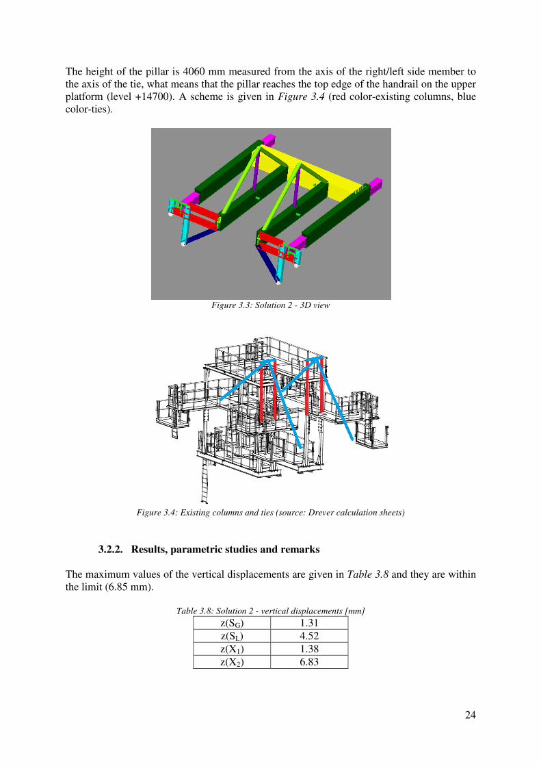
The height of the pillar is 4060 mm measured from the axis of the right/left side member to the axis of the tie, what means that the pillar reaches the top edge of the platform (level +14700). A scheme is given color-ties).
Figure 3.4: Existing columns and ties (source: Drever calculation sheets)
3.2.2. Results, parametric studies and remarks
The maximum values of the vertical displacements are giventhe limit (6.85 mm).
Table
The height of the pillar is 4060 mm measured from the axis of the right/left side member to the axis of the tie, what means that the pillar reaches the top edge of the handrail on the upper
A scheme is given in Figure 3.4 (red color-existing columns, blue
Figure 3.3: Solution 2 - 3D view
: Existing columns and ties (source: Drever calculation sheets)
Results, parametric studies and remarks
The maximum values of the vertical displacements are given in Table 3.8
Table 3.8: Solution 2 - vertical displacements [mm]
z(SG) 1.31 z(SL) 4.52 z(X1) 1.38 z(X2) 6.83
24
The height of the pillar is 4060 mm measured from the axis of the right/left side member to handrail on the upper
existing columns, blue
: Existing columns and ties (source: Drever calculation sheets)
and they are within

25
The vertical reactions are represented in Table 3.9. Compared to Model for the calibration the difference is 23.19 kN what results in the saving of steel for 2274.94 kg and expressed in percentages, around 8%. Additionally, a certain amount of material could be saved by the utilization of the existing platform columns (in the finite element model the pillar has been modeled using CHS 273x10). The fact that this solution has smaller number of roller bogies has to be accounted for the final cost.
Table 3.9: Solution 2 - vertical reactions [kN]
R1(SG) 93.56 R2(SG) 102.30 R3(SG) 103.96 R4(SG) 103.44
Σ 403.26
The horizontal reactions are given in Table 3.10. The increased value of the horizontal reactions can be regarded as a drawback of this solution. They act on the runway beams, for example on one beam by maximum shear action of R3=475.17 kN, R7=-469.12 kN and torque of T(R3,R7) =864.26 kNm compared to the meximum reactions from the initial solution R1=420.65 kN, R5=-452.59 kN and torque of T(R1,R5) =797.77 kNm what means that the acting torque is 8% higher and it can influence the dimensions of the runway beams, although the runway beams itself are beyond the scope of this Thesis.
Table 3.10: Solution 2 - horizontal reactions R(X2,ULS )[kN]
R1 R2 R3 R4 R5 R6 R7 R8 / / 475.17 397.36 / / -469.12 -391.31
Regarding the ultimate limit states, Table 3.11 shows the maximum values of elastic stresses (ULS) and it is obvious that the ultimate limit states are not governing for the design. For instance, the maximum value in Table 3.11 is 73.88 MPa, what is only 31% of the yield strength.
Table 3.11: Solution 2 - stress σ(X2,ULS), absolute values [MPa]
Right side member 42.78 Left side member 44.63 Connecting beam 73.88 Pillar 52.74 Tie 41.42
It is worthy to be mentioned that the design buckling resistance of the pillar, which is loaded in compression, is only slightly lower than the design ultimate resistance of its cross-section. This is proved by calculating the reduction factor, what is given in Table 3.12.
Table 3.12: Solution 2 - Buckling reduction factor χ
Pillar Lcr [mm] 4060
λ 43.61 χ 0.86
26
The ties are placed in the vertical plane that coincides with the axis of the side member and they pass through the platforms area and may limit the accessibility for maintenance workers. A case study analyzing the influence of the stiffness of parts of the bowstring structure on the overall behavior has been conducted. Variable parameters are the area of the pillar and tie. For the study, their cross-sectional areas are multiplied by 0.25, 0.5, 0.75, 1, 2, 4 and 10 and lastly selected to be infinitely stiff. The influence is analyzed through the resulting deflections (load combination X2). The initial values of cross-sectional area are indicated in Table 3.13.
Table 3.13: Cross-sectional area (pillar and tie)
Pillar CHS 273x10 Ap=8262 mm2 Tie CHS 273x12.5 At=10230 mm2
First, the cross-sectional area of the tie is set as a constant and the cross-section of the pillar is subjected to the variation. The resulting values are illustrated in Table 3.14.
Table 3.14: Vertical displacements (cross-section of the pillar is variable)
Multiplier Ap [mm2]
z(X2) [mm]
0.25 2065.5 7.65 0.50 4131 7.16 0.75 6196.5 6.95
1 8262 6.83 2 16524 6.65 4 33048 6.59
10 82620 6.66 Infinite / 6.32
Second, the cross-sectional area of the pillar is set as a constant and the cross-section of the tie is subjected to the variation. The resulting values are illustrated in Table 3.15.
Table 3.15: Vertical displacements (cross-section of the tie is variable)
Multiplier At [mm2]
z(X2) [mm]
0.25 2557.5 7.89 0.50 5115 7.30 0.75 7672.5 7
1 10230 6.83 2 20460 6.57 4 40920 6.51
10 102300 6.78 Infinite / 6.02
If both members are selected as infinite stiff, the corresponding deflection is 5.28 mm what is theoretically the lowest value and it can be further influenced only by changing the stiffness of the beam.

Figure 3
Figure 3.5 represents a graphical interpretation of seen from the graph, any significant enhancement of the selected crosscannot provide a benefit in terms of the overall behavior of the structure. tie is two times stiffer, the deflections are lower foconsiderably higher. If the crossthe displacements will be even the tie is increased at the same time (the analysis has been conducted for load combination Xwhere figures the dead weight).properties were selected. A case study related to the position of the bowstring members has been conduThe position of three nodes have been one node is shifted while other two re
Figure
Table 3
Node shift [m] 0.5 1
1.5 2
6
6,2
6,4
6,6
6,8
7
7,2
7,4
7,6
7,8
8
0 1 2 3
De
fle
cto
ns
[mm
]
3.5: Diagram area multiplier vs deflections [mm]
represents a graphical interpretation of Table 3.14 and Table 3.15
seen from the graph, any significant enhancement of the selected crosscannot provide a benefit in terms of the overall behavior of the structure. tie is two times stiffer, the deflections are lower for only 0.18 mm while the cost is
If the cross-sectional area of the tie is multiplied more than three times, even higher (red line on the graph) due to the fact that the weight of ame time (the analysis has been conducted for load combination X
where figures the dead weight). It can be concluded that the appropriate cross
A case study related to the position of the bowstring members has been conduThe position of three nodes have been shifted according to Figure 3.6. In each iteration only one node is shifted while other two remain on their initial positions.
Figure 3.6: Horizontal shifting of nodes - designation
3.16: Node shift [m] vs vertical deflections [mm]
Deflections - max. values [mm] TL TR PL
6.95 7.04 6.97 6.767.14 7.28 7.14 6.847.38 7.55 7.36 7.037.68 7.87 7.61 7.29
3 4 5 6 7 8 9 10 11
Area multiplier
27
Table 3.15. As it can be seen from the graph, any significant enhancement of the selected cross-section properties
For instance, if the r only 0.18 mm while the cost is
sectional area of the tie is multiplied more than three times, higher (red line on the graph) due to the fact that the weight of
ame time (the analysis has been conducted for load combination X2 the appropriate cross-section
A case study related to the position of the bowstring members has been conducted as well. In each iteration only
PR 6.76 6.84 7.03 7.29
Constant At
Constant Ap

Figure 3
Figure 3.7 shows a graphical representation of structure provides the highest rigidity to the system if the ties are anbeam (a value of the node shift in this case is 0 m). m) a slightly smaller values of the deflections can be obtained, what results mainly because of the positions of applied loads. because the initial position (PR=0 m) corresponds to the can be utilized as a part of the bowstring structure. The influence of the column height has been analyzed according to Figure 3.8.
Figure
Table 3
6,6
6,8
7
7,2
7,4
7,6
7,8
8
0 0,5
De
fle
ctio
ns
[mm
]
3.7: Diagram node shift [m] vs deflections [mm]
shows a graphical representation of Table 3.16. As it is obvious, the bowstring structure provides the highest rigidity to the system if the ties are anchored at the ends of the beam (a value of the node shift in this case is 0 m). By shifting the pillar to the right (PR=0.5
s of the deflections can be obtained, what results mainly because of the positions of applied loads. This shift has not been included in the proposed solution because the initial position (PR=0 m) corresponds to the position of the platform column that
be utilized as a part of the bowstring structure.
The influence of the column height has been analyzed by shifting its top node downwards
Figure 3.8: Vertical shifting of nodes - designation
3.17: Node shift [m] vs vertical deflections [mm]
Node shift [m]
Deflections [mm]
0.5 6.87 1 6.95
1.5 7.12 2 7.41
2.5 7.87
0,5 1 1,5 2 2,5
Node shift [m]
28
As it is obvious, the bowstring chored at the ends of the
By shifting the pillar to the right (PR=0.5 s of the deflections can be obtained, what results mainly because of
This shift has not been included in the proposed solution platform column that
by shifting its top node downwards
TL
TR
PL
PR

Figure 3
Figure 3.9 shows a graphical representation of structure loses its rigidity. It can be explained on the level of internal forces in the tie.
Figure 3.10: Resolving force N to the horizontal and vertical component
When the tensile force N in the tie, showvertical component as follows:
As the angle α decreases, the sinus function gives a smaller value and consequently a smaller value of the vertical component. At the same time by lowering the angle the horizontal component gets a higher value. supported in the vertical direction in order to decrease the deflections, the vertical component of the tensile force should be utilized as much as possible what means that a higher value of the angle α has the positive effect on the ovehigher value of the horizontal component acts adversely to the beam because it introduces higher compressive forces to the beam, what can cause stability problems.solution the angle has been sedge of the handrail on the upper platform. the pillar towards the overhanging side of the structure, overall behavior as it was already explained, because the pillar is farther from the connecting beam which acts as a support.
6,6
6,8
7
7,2
7,4
7,6
7,8
8
0 0,5
De
fle
ctio
ns
[mm
]
3.9: : Diagram node shift [m] vs deflections [mm]
shows a graphical representation of Table 3.17. By shortening the pillar the It can be explained on the level of internal forces in the tie.
: Resolving force N to the horizontal and vertical component
When the tensile force N in the tie, shown in Figure 3.10, is resolved to its horizontal and vertical component as follows: = ∙ cos � � = ∙ sin �
decreases, the sinus function gives a smaller value and consequently a smaller value of the vertical component. At the same time by lowering the angle the horizontal component gets a higher value. Since the overhanging side of the structure needs to be supported in the vertical direction in order to decrease the deflections, the vertical component of the tensile force should be utilized as much as possible what means that a higher value of
has the positive effect on the overall behavior of the structure. In addition, higher value of the horizontal component acts adversely to the beam because it introduces higher compressive forces to the beam, what can cause stability problems.
has been selected as the highest possible since the pillar reaches the top edge of the handrail on the upper platform. Generally, the angle may be increased by shifting the pillar towards the overhanging side of the structure, but the shift does not affect the
ll behavior as it was already explained, because the pillar is farther from the connecting beam which acts as a support.
0,5 1 1,5 2 2,5 3
Node shift [m]
29
By shortening the pillar the It can be explained on the level of internal forces in the tie.
: Resolving force N to the horizontal and vertical component
, is resolved to its horizontal and
decreases, the sinus function gives a smaller value and consequently a smaller value of the vertical component. At the same time by lowering the angle the horizontal
ucture needs to be supported in the vertical direction in order to decrease the deflections, the vertical component of the tensile force should be utilized as much as possible what means that a higher value of
rall behavior of the structure. In addition, a higher value of the horizontal component acts adversely to the beam because it introduces higher compressive forces to the beam, what can cause stability problems. In the proposed
elected as the highest possible since the pillar reaches the top Generally, the angle may be increased by shifting
but the shift does not affect the ll behavior as it was already explained, because the pillar is farther from the connecting
H

A possible modification of the right/left side member that satisfies the deflection criterion(z(X2)=6.88mm and may be regarded as satprofile HEB1000 instead of theCHS 273x16 instead of CHS 273x12.5 for the tie. kN, what is only 0.82 kN more compared to be subjected to stability problems, because I sections are more prone to lateralbuckling, axial (compression) forces are intrlength is 9723 mm (λz=152).
3.3. Solution 3
3.3.1. General layout
Solution 3 is a variant of Solution structure. The bowstring structure has a different configuration compared to Solution 2. It consists of two pillars and a polygonal tie (slopethis case is more stiff what allows the beam crossreducing the thickness of plates.and Figure 3.12. Beside the different crosssupporting beams, all other coroller bogies for the horizontal reactions (instead of eight used in the initial solution) and a corresponding number of brackets. axis of the right/left side member to the axis of the tie.existing platform columns because their positions does not coincide to the positions of the pillars. The horizontal part of the tie passes through the platforms area andaccessibility for maintenance workers
Figure
of the right/left side member that satisfies the deflection criterion)=6.88mm and may be regarded as satisfactory) could be obtained by using a hot rolled
the built-up box girder (right and left side member)CHS 273x16 instead of CHS 273x12.5 for the tie. The vertical reactions in total are 404.08
kN more compared to the basic Solution 2. In this case, the beam may be subjected to stability problems, because I sections are more prone to lateralbuckling, axial (compression) forces are introduced to the beam from the tie and
General layout
is a variant of Solution 2 and comprises of built-up girdersstructure. The bowstring structure has a different configuration compared to Solution 2. It consists of two pillars and a polygonal tie (slope-horizontal-slope). The bowstring structure in this case is more stiff what allows the beam cross-sections to be reduced, mainly by means of reducing the thickness of plates. An overview of the structural layout is given
Beside the different cross-sections used for the side members and the , all other considerations are remaining from Solution 2, like the use of four
roller bogies for the horizontal reactions (instead of eight used in the initial solution) and a corresponding number of brackets. The height of the pillars is 4060 mm measured from the
of the right/left side member to the axis of the tie. This solution cannot utilize the existing platform columns because their positions does not coincide to the positions of the pillars. The horizontal part of the tie passes through the platforms area andaccessibility for maintenance workers what means that the platforms might be rearranged.
Figure 3.11: Solution 3 - 3D view
Figure 3.12: Solution 3 - 2D view (elevation)
30
of the right/left side member that satisfies the deflection criterion by using a hot rolled
(right and left side member) and by using The vertical reactions in total are 404.08
In this case, the beam may be subjected to stability problems, because I sections are more prone to lateral-torsional
oduced to the beam from the tie and the buckling
up girders and a bowstring structure. The bowstring structure has a different configuration compared to Solution 2. It
slope). The bowstring structure in sections to be reduced, mainly by means of
An overview of the structural layout is given in Figure 3.11 the side members and the
nsiderations are remaining from Solution 2, like the use of four roller bogies for the horizontal reactions (instead of eight used in the initial solution) and a
ight of the pillars is 4060 mm measured from the This solution cannot utilize the
existing platform columns because their positions does not coincide to the positions of the pillars. The horizontal part of the tie passes through the platforms area and may limit the
what means that the platforms might be rearranged.

In the finite element model crossgiven in Table 3.18 and Table 3.19
Beam
Initial solution
Right and left side member Right and left supporting beam Right and left supporting beam (on the supports)
Solution 3
Right and left side member Right and left supporting beam Right and left supporting beam (on the supports)
Table 3
3.3.2. Results, parametric studies and remarks
The maximum values of the vertical displacemenTable 3.20 and they are not beyond
Table
In the finite element model cross-sections that have been used for the structural members are Table 3.19.
Table 3.18: Solution 3 - cross-sections
bf1
[mm] tf1
[mm] bf2
[mm] tf2
[mm] h
[mm]Right and left side member 680 15 680 15 1135Right and left supporting
524 15 524 15 1135
Right and left supporting supports)
524 25 524 15 600
Right and left side member 524 12 524 12 1135Right and left supporting
524 12 524 12 1135
Right and left supporting supports)
524 15 524 15 600
3.19: Solution 3 - cross-sections (pillar and tie)
Pillar CHS 219.1x10 Tie CHS 273x12.5
Results, parametric studies and remarks
s of the vertical displacements reached in the structure not beyond the limiting value (6.85 mm)
Table 3.20: Solution 3 - vertical displacements [mm]
z(SG) 1.31 z(SL) 4.55 z(X1) 1.37 z(X2) 6.85
31
have been used for the structural members are
hw
[mm] tw
[mm] d
[mm] 1135 12 556
1135 12 400
600 12 400
1135 10 400
1135 10 400
600 12 400
ts reached in the structure are provided in

32
The vertical reactions are represented in Table 3.21. Compared to Model for the calibration the difference is 41.25 kN what results in the saving of steel for 4046.63 kg and expressed in terms of percentages, approximately 15%.
Table 3.21: Solution 3 - vertical reactions [kN]
R1(SG) 89.60 R2(SG) 98.08 R3(SG) 99.10 R4(SG) 98.42
Σ 385.20 Table 3.22 presents the horizontal reactions. The values are almost identical to the values obtained for Solution 2. They are higher than the values in the initial solution what can be considered as a drawback of this solution. The difference of torque acting on the runway beam is approximately 9% (871.76 kNm compared to 797.77 kNm).
Table 3.22: Solution 3 - horizontal reactions R(X2,ULS )[kN]
R1 R2 R3 R4 R5 R6 R7 R8 / / 479.10 399.97 / / -473.40 -394.26
Regarding the ultimate limit states, Table 3.23 shows the maximum values of elastic stresses (ULS) and similarly to Solution 2 the ultimate limit states are not governing for the design. For instance, the maximum value in Table 3.24 is 73.02 MPa, what is only 31% of the yield strength.
Table 3.23: Solution 3 - stress σ(X2,ULS), absolute values [MPa]
Right side member 48.35 Left side member 53.16 Connecting beam 73.02 Pillar 41.97 Tie 43.08
Similarly to Solution 2, the pillars are not influenced much by stability problems what confirms the buckling reduction factor calculated in Table 3.24.
Table 3.24: Solution 3 - Buckling reduction factor χ
Pillar Lcr [mm] 4060
λ 54.86 χ 0.79
Generally, the bowstring configuration used for Solution 3 can be regarded as more efficient than the configuration used for Solution 2 what is obvious from the weight of the structure. This can be explained on a simple example. An illustration is provided in Figure 3.13. If we assume the whole bowstring structure working as a sole cross-section with variable properties along its axis, the moment of inertia varies from Ibeam to Imax. For Solution 2, the maximum value (Imax) is obtained only in one cross-section, above the pillar, while the configuration that uses two pillars has the maximum moment of inertia on complete length between the pillars, what is the reason of Solution 3 being more rigid. On the other hand, Solution 3

requires more joints to connect the members. The bowstring structure might limit the accessibility for maintenance workers and overlap with some equipment.
Figure
3.4. Solution 4
3.4.1. General layout
This solution shows a completely different idea compared to previous three solutions. It is composed of two box trusses mutually connected by a planar truss perpendicular to them. The box truss has trapezoidal crossconsiderably stiffer than the bottom chords because As a simplification compared to previous solutions, this structure does not contain any welded built-up member, but on contrary it requires morethe joints. The structure consists of square hollow sections used as chords and circular hollow sections used as braces. Circular hollow sections have been selected due to the reason that the braces are spatial members and(see Table 3.25). Three different crossthe material. Generally, according to the structural mechanics, a trapezoidal shape composed of simple connected bars is not indiagonal might be used, what is applied here as well, rather than obtaining the frame effect what would be quite difficult in this case.axis) is 2750 mm. A graphical overview of the structure is given dimensions in Figure 3.15. The positions of the vertical supports are the same as they are from previously proposed solutions. of the truss, what is illustrated almost entirely prepared in a workshop. The size limitations, they could be transported to the site connecting truss. As a result, the majority of the necessawhat increases the quality and speeds In the finite element model, the chords are regarded as continuous and the braces as pinconnected.
o connect the members. The bowstring structure might limit the accessibility for maintenance workers and overlap with some equipment.
Figure 3.13: Moment of inertia - bowstring structure
General layout
This solution shows a completely different idea compared to previous three solutions. It is composed of two box trusses mutually connected by a planar truss perpendicular to them. The box truss has trapezoidal cross-section with four chords. Its upper chords are considerably stiffer than the bottom chords because the loading is imposed between nodes. As a simplification compared to previous solutions, this structure does not contain any
ember, but on contrary it requires more labor and equipment to construct The structure consists of square hollow sections used as chords and circular hollow
sections used as braces. Circular hollow sections have been selected due to the reason that the braces are spatial members and it is easier in this case to connect CHS to the chord than SHS
Three different cross-section sizes are selected for braces in orGenerally, according to the structural mechanics, a trapezoidal shape composed
imple connected bars is not in-plane stiff. To obtain the in-plane stiffness, an additional diagonal might be used, what is applied here as well, rather than obtaining the frame effect what would be quite difficult in this case. The vertical distance between the chords (axis
A graphical overview of the structure is given in Figure 3.14
The positions of the vertical supports are the same as they are from previously proposed solutions. The horizontal roller bogies are placed at the edge nodes of the truss, what is illustrated in Figure 3.16 with the designation. The structure could be almost entirely prepared in a workshop. The size of one box-truss complies with the traffic
could be transported to the site one by one and there intercoconnecting truss. As a result, the majority of the necessary work is moved to a workshop, what increases the quality and speeds-up the construction.
model, the chords are regarded as continuous and the braces as pin
33
o connect the members. The bowstring structure might limit the
This solution shows a completely different idea compared to previous three solutions. It is composed of two box trusses mutually connected by a planar truss perpendicular to them.
Its upper chords are the loading is imposed between nodes.
As a simplification compared to previous solutions, this structure does not contain any and equipment to construct
The structure consists of square hollow sections used as chords and circular hollow sections used as braces. Circular hollow sections have been selected due to the reason that the
nnect CHS to the chord than SHS section sizes are selected for braces in order to save
Generally, according to the structural mechanics, a trapezoidal shape composed plane stiffness, an additional
diagonal might be used, what is applied here as well, rather than obtaining the frame effect en the chords (axis-to-
Figure 3.14 and the The positions of the vertical supports are the same as they are
The horizontal roller bogies are placed at the edge nodes The structure could be
complies with the traffic and there interconnected by the
ry work is moved to a workshop,
model, the chords are regarded as continuous and the braces as pin-

Figure 3.
Upper chordBottom chordBraceBrace (type 2)Brace (type 3)
Figure 3.14: Solution 4 - 3D view
Figure 3.15: Solution 4 - dimensions
.16: Solution 4 - horizontal reactions (designation)
Table 3.25: Solution 4 - cross-sections
Upper chord SHS 400x400x12.5 Bottom chord SHS 250x250x10 Brace (type 1) CHS 88.9x6.3 Brace (type 2) CHS 168.3x6 Brace (type 3) CHS 168.3x8
34

35
3.4.2. Results, parametric studies and remarks
As it was done previously, the deflection criterion is the first to be mentioned. The maximum obtained deflection for Solution 4 is 6.77 mm, what is within the limits and the values for all load cases/combinations are given in Table 3.26. The vertical displacements resulting from the dead weight are lower here than for the initial solution, what is the first sign that the structure has higher stiffness-to-weight ratio.
Table 3.26: Solution 4 - vertical displacements [mm]
z(SG) 1.07 z(SL) 4.68 z(X1) 1.12 z(X2) 6.77
The structure is significantly lighter than the initial and all other previously proposed solutions. In numbers, the sum of the vertical reactions resulting from the dead weight is 330.06 kN (see Table 3.27), what is 96.39 kN lower in comparison to model for the calibration. This means that Solution 4 allows approximately 10 t of steel to be saved. On the other hand, the production of this structure is more expensive since the joints are complex. A compromise between the labor cost and the saving of steel should be assessed by the manufacturer.
Table 3.27: Solution 4 - vertical reactions [kN]
R1(SG) 85.87 R2(SG) 88.51 R3(SG) 78.13 R4(SG) 78.09
Σ 330.06
Table 3.28 presents the horizontal reactions resulting from load combination X2. The values are lower than the values calculated in Model for the calibration, what is one more advantage of this solution. The maximum horizontal reaction calculated here is for 55.12 kN lesser than the maximum from model for the calibration. This may result in the reduction of cross-section properties used for the runway beams, what leads to an additional saving.
Table 3.28: Solution 4 - horizontal reactions R(X2,ULS )[kN]
R1 R2 R3 R4 R5 R6 R7 R8 217.37 185.40 397.47 328.47 -211.17 -178.97 -395.22 -326.46
Table 3.29 is an overview of the maximum values of elastic stresses (ULS). As it is obvious, the elastic stress reaches 53% of the yield strength what means that the ultimate limit states are not governing for the design. It is worthy to be mentioned that the range of stresses is higher than it was in previous solutions (usually it was 30-40% of the yield strength), what means that this structure utilizes better its structural members and provide enough stiffness at the same time. The buckling reduction factor for some members is given in Table 3.30. The buckling length here is taken equal to the system length although a reduction is possible. Compared to other proposed solutions, this is more susceptible to stability problems because its structural members are more slender, thus some of them may need to be strengthened

during the detailed design (for example, the brace in the horizontal plane next to the horizontal support).
Table 3.29: Solution 4
Upper chordBottom chordInternal braces (inplane stiffeners)Horizontal plane bracesInclined plane braces
The direction of the internal braces (inthey are loaded only in tension.
Table
Cross-sectionLcr [mm]
λ
χ
A feasibility of this solution is mainly dependent on design and construction of joints. Some of them are very complex due to the fact that the structure is spatial and in certainbraces are connected (an example given horizontal plane are connected to the chord, three braces in the inclined plane and one internal brace as well. This requires a precise production and a special equipment to cut the members properly, for example a laser cutter. 1993-1-8, which provides a limited amount of rules for design of multiplanar joints (only for the most common configurations). For design of joints that are not covered by EN 1993a finite element analysis may be used what is sometimes time consuming and requires an advanced knowledge.
Figure
during the detailed design (for example, the brace in the horizontal plane next to the
: Solution 4 - stress σ(X2,ULS), absolute values [MPa]
Upper chord 103.82 Bottom chord 57.60 Internal braces (in-plane stiffeners)
124.50
Horizontal plane braces 99.66 Inclined plane braces 115.47
The direction of the internal braces (in-plane stiffeners) has been selected in such a they are loaded only in tension.
Table 3.30: Solution 4 - Buckling reduction factor χ
Horizontal plane brace
Inclined plane brace
section CHS 88.9x6.3 CHS 168.3x8 [mm] 4041 3871 λ 29.91 68.27 χ 0.32 0.71
A feasibility of this solution is mainly dependent on design and construction of joints. Some of them are very complex due to the fact that the structure is spatial and in certainbraces are connected (an example given in Figure 3.17). As it is presented, three braces in the horizontal plane are connected to the chord, three braces in the inclined plane and one
requires a precise production and a special equipment to cut the example a laser cutter. Joints should be designed according to EN
8, which provides a limited amount of rules for design of multiplanar joints (only for the most common configurations). For design of joints that are not covered by EN 1993
may be used what is sometimes time consuming and requires an
Figure 3.17: Solution 4 - example of a complex joint
36
during the detailed design (for example, the brace in the horizontal plane next to the
plane stiffeners) has been selected in such a way that
A feasibility of this solution is mainly dependent on design and construction of joints. Some of them are very complex due to the fact that the structure is spatial and in certain nodes 4-6
. As it is presented, three braces in the horizontal plane are connected to the chord, three braces in the inclined plane and one
requires a precise production and a special equipment to cut the Joints should be designed according to EN
8, which provides a limited amount of rules for design of multiplanar joints (only for the most common configurations). For design of joints that are not covered by EN 1993-1-8,
may be used what is sometimes time consuming and requires an

The structure itself does not overlap with Figure 3.18. The drag chain assembly, which was just below the carriage and supported by the runway frame, should be moved downwards, below the bottom chords of the carriage assembly. As an advantage of Solution 4 is also the fact that the structure is accessible fromall sides and it allows some equipment to pass through the structure if it is necessary, what is not the case when box girders are used.
Figure 3.18: Solution 4 -
3.5. Solution 5
3.5.1. General layout
Solution 5 has been developed using structure consists of two triangularperpendicular to them. A triangby means of pinned joints is inallows Solution 5 to have lesser number of brace members than Solution 4. chords square hollow sections are selected because they are exposed to the between nodes.. The bottom chord has to support the horizontal roller bogies at its ends and to provide the stiffness in the horizontal plane, therefore a rectangular hollow sectoriented with its higher dimension hollow sections in order to simplify the construction of spatial joints. cross-sections are used for the braces. vertical distance between the chords (axisstructural layout is given in Figure 3.19
vertical are on the same positions as they are in Solution 4 and the same designation will be used here (see Figure 3.16).workshop, transported to the site trusstruss, what increases the quality and speeds
The structure itself does not overlap with any secondary assembly, what is illustrated The drag chain assembly, which was just below the carriage and supported by
the runway frame, should be moved downwards, below the bottom chords of the carriage assembly. As an advantage of Solution 4 is also the fact that the structure is accessible fromall sides and it allows some equipment to pass through the structure if it is necessary, what is not the case when box girders are used.
- complete carriage assembly (source: Drever calculation sheets)
General layout
has been developed using a similar concept as it was used for triangular box trusses mutually connected by a planar truss
A triangular structure composed of three members mutually connected inned joints is in-plane stiff, what was not the case for a trapezoidal shape.
to have lesser number of brace members than Solution 4. re hollow sections are selected because they are exposed to the
The bottom chord has to support the horizontal roller bogies at its ends and to provide the stiffness in the horizontal plane, therefore a rectangular hollow sectoriented with its higher dimension in the horizontal plane. Braces are composed
to simplify the construction of spatial joints. Two different sizes of sections are used for the braces. The selected profiles are previewed in
vertical distance between the chords (axis-to-axis) is 2750 mm. A graphical illustration of the Figure 3.19 and Figure 3.20. Supports, both the horizontal and
on the same positions as they are in Solution 4 and the same designation will be ). Similarly to Solution 4, the structure can be prepared in a
workshop, transported to the site truss-by-truss and there interconnected by the connwhat increases the quality and speeds-up the construction as it was already mentioned.
37
what is illustrated in The drag chain assembly, which was just below the carriage and supported by
the runway frame, should be moved downwards, below the bottom chords of the carriage assembly. As an advantage of Solution 4 is also the fact that the structure is accessible from all sides and it allows some equipment to pass through the structure if it is necessary, what is
r calculation sheets)
for Solution 4. The box trusses mutually connected by a planar truss
ular structure composed of three members mutually connected plane stiff, what was not the case for a trapezoidal shape. This
to have lesser number of brace members than Solution 4. For the upper re hollow sections are selected because they are exposed to the applied loads
The bottom chord has to support the horizontal roller bogies at its ends and to provide the stiffness in the horizontal plane, therefore a rectangular hollow section is used,
Braces are composed of circular Two different sizes of
The selected profiles are previewed in Table 3.31. The A graphical illustration of the
Supports, both the horizontal and on the same positions as they are in Solution 4 and the same designation will be
Similarly to Solution 4, the structure can be prepared in a truss and there interconnected by the connecting up the construction as it was already mentioned.

In the finite element model, the chords are considered as continuous and the braces as pinconnected.
Upper chordBottom chordBrace (type 1)Brace (type 2)
3.5.2. Results, parametric studies and remarks
The maximum values of the vertical displacements are given in within the limit (6.85 mm).
Table
In the finite element model, the chords are considered as continuous and the braces as pin
Figure 3.19: : Solution 5 - 3D view
Figure 3.20: Solution 5 - dimensions
Table 3.31: Solution 5 - cross-sections
Upper chord SHS 400x400x12.5 Bottom chord RHS 400x200x10 Brace (type 1) CHS 88.9x5 Brace (type 2) CHS 168.3x10
Results, parametric studies and remarks
The maximum values of the vertical displacements are given in Table 3.32
Table 3.32: Solution 5 - vertical displacements [mm]
z(SG) 1.07 z(SL) 4.73 z(X1) 1.12 z(X2) 6.84
38
In the finite element model, the chords are considered as continuous and the braces as pin-
Table 3.32 and they are
39
The sum of the vertical reactions is 320 kN as it can be seen in Table 3.33. Compared to model for the calibration, the difference in the vertical reactions resulting from the dead weight is 106.45 kN, what means that Solution 5 is around 38% lighter than the initial solution. This leads to the saving of 10.5 t of steel. The amount could be higher but that can be estimated only after the detailed design, since Model for the calibration does not take into account the weight of some secondary parts of the structure (for example diaphragms) that are not structural part of a truss girder. On the contrary, Solution 5 requires more labor for the production compared to solutions composed of built-up box girders and the joints are more complex as well.
Table 3.33: Solution 5 - vertical reactions [kN]
R1(SG) 83.63 R2(SG) 86.00 R3(SG) 75.31 R4(SG) 75.06
Σ 320.00 The horizontal reactions resulting from load combination X2 are given in Table 3.34. They are slightly higher than the values calculated in Solution 4, but still are lower than the values obtained in Model for the calibration, what can be regarded as an advantage of Solution 5, because it can lead to the reduction of cross-section properties of the runway structure.
Table 3.34: Solution 5 - horizontal reactions R(X2,ULS )[kN]
R1 R2 R3 R4 R5 R6 R7 R8 241.20 212.23 405.95 336.08 -183.44 152.88 -384.54 -316.27
The elastic normal stresses (ULS), resulting from load combination X2 calculated for the most loaded structural members are given in Table 3.35. Their values are of the same range as the values calculated for Solution 4 and the same remarks are applicable here. The maximum utilization ratio is 0.49, what means that only 49% of the yield strength is exploited. To show the influence of stability problems on the design resistance of a member, the buckling reduction factors are given in Table 3.36. The buckling length here is taken equal to the system length despite a reduction is possible. The diagonal brace next to the horizontal support might need to be strengthened during the detailed design due to the buckling.
Table 3.35: Solution 5 - stress σ(X2,ULS), absolute values [MPa]
Upper chord 115.52 Bottom chord 64.66 Horizontal plane braces 82.64 Inclined plane braces 114.89
Table 3.36: Solution 5 - Buckling reduction factor χ
Horizontal plane brace
Inclined plane brace
Cross-section CHS 88.9x5 CHS 168.3x10 Lcr [mm] 4041 4096
λ 136.06 73.01 χ 0.33 0.68

Solution 5 has a lower number of braces compared to Solution 4, what is an advantage from the manufacturing point of view and may make this structure more feasible. Some joints became simpler, like the joint given bottom chord. On the contrary, some of them are still complex, what is illustrated 3.22, where six brace members (two diagonals and one vertical in each of the inclined planes) are connected to the bottom chord in a node. A recomplexity by decreasing number of
Figure 3.21: Solution 5 - example of
a simple joint
Similarly to Solution 4, in Solution 5 the structure itself does not overlap with any subassembly of the carriage, what is displayed advantage. The drag chain assembly, supported by the runway frame should be modownwards as it was mentioned for Solution 4 as well.
Figure 3.23: Solution 5 -
a lower number of braces compared to Solution 4, what is an advantage from the manufacturing point of view and may make this structure more feasible. Some joints became simpler, like the joint given in Figure 3.21, where two braces are connected to the
contrary, some of them are still complex, what is illustrated , where six brace members (two diagonals and one vertical in each of the inclined planes)
are connected to the bottom chord in a node. A re-arrangement of the braces may simplify the complexity by decreasing number of members connected together in a node.
example of Figure 3.22: Solution 5
a complex joint
Similarly to Solution 4, in Solution 5 the structure itself does not overlap with any subassembly of the carriage, what is displayed in Figure 3.23 and can be considered as an advantage. The drag chain assembly, supported by the runway frame should be modownwards as it was mentioned for Solution 4 as well.
- complete carriage assembly (source: Drever calculation sheets)
40
a lower number of braces compared to Solution 4, what is an advantage from the manufacturing point of view and may make this structure more feasible. Some joints
where two braces are connected to the contrary, some of them are still complex, what is illustrated in Figure
, where six brace members (two diagonals and one vertical in each of the inclined planes) arrangement of the braces may simplify the
connected together in a node.
: Solution 5 - example of
a complex joint
Similarly to Solution 4, in Solution 5 the structure itself does not overlap with any sub-and can be considered as an
advantage. The drag chain assembly, supported by the runway frame should be moved
complete carriage assembly (source: Drever calculation sheets)

Since the distance between the bottom chord and the railapproximately 1000 mm (measured from the outer face of the chordadditional structural member is necessary to support the roller bogie and connect it to the chord. As a simplification, this member was although it should be stiff enough between the bogie and the rail.
Figure 3.24: Solution 5
3.6. Solution 6
3.6.1. General layout
The structure is composed of planar trusses (side members and supporting beams) and the connecting beam that can be described the most closely as a box truss, although it does not have diagonal braces in the horizontal planes (see increased compared to the initial solution. Here, the distance (axischords is 1500 mm and the roller bogies supporting the structure vertically below the bottom chord. The main aim of this solution is to avoid the production of builtbox girders and to utilize the commercial hollow sections. the chords of the connecting beam is 1020 mm (axissections are used, with two different crossand the dimensions are designated subjected to the applied loads between nodesupper and lower chords in order to enhance the overall stiffness of the structure and the deflection criterion. For geometry, stiffness of the structure. Braces are depending on their position in the structure. support between the brackets on the motor side of the structure has beenin order to suit the geometry of the truss (its position now is on the half distance between the brackets). The horizontal roller bogies remain solution. The chords are intended to be continuous, weldedwhile the braces are welded to the chords. Considering their sizes and consequently their second moment of area, the best approximation for this situation is to model the chords as continuous and the braces as pinelement model.
Since the distance between the bottom chord and the rail for the horizontal reactions is approximately 1000 mm (measured from the outer face of the chord, see additional structural member is necessary to support the roller bogie and connect it to the
As a simplification, this member was not modeled in the finite element model, it should be stiff enough to avoid deformations and to allow a proper contact
between the bogie and the rail.
: Solution 5 - bottom chord (source: Drever calculation sheets)
General layout
The structure is composed of planar trusses (side members and supporting beams) and the connecting beam that can be described the most closely as a box truss, although it does not
horizontal planes (see Figure 3.25). The height of the structure is increased compared to the initial solution. Here, the distance (axis-to-chords is 1500 mm and the roller bogies supporting the structure vertically
The main aim of this solution is to avoid the production of builtbox girders and to utilize the commercial hollow sections. The horizontal distance between the chords of the connecting beam is 1020 mm (axis-to-axis). For the chords, square hollow sections are used, with two different cross-sectional thicknesses in order to save the material
are designated in Figure 3.25 as well. Although the upper chord is applied loads between nodes, the same cross-section size is used for both chords in order to enhance the overall stiffness of the structure and
For geometry, a Warren truss with verticals is selected to increase the Braces are composed of rectangular and square hollow sections,
depending on their position in the structure. Compared to the initial solution, the vertical support between the brackets on the motor side of the structure has been moved for 182
geometry of the truss (its position now is on the half distance between the The horizontal roller bogies remain at the same position as they are in the initial
The chords are intended to be continuous, welded mutually by means while the braces are welded to the chords. Considering their sizes and consequently their second moment of area, the best approximation for this situation is to model the chords as continuous and the braces as pin-connected to the chords what has been done in the finite
41
for the horizontal reactions is , see Figure 3.24), an
additional structural member is necessary to support the roller bogie and connect it to the not modeled in the finite element model,
to avoid deformations and to allow a proper contact
e: Drever calculation sheets)
The structure is composed of planar trusses (side members and supporting beams) and the connecting beam that can be described the most closely as a box truss, although it does not
The height of the structure is -axis) between the
chords is 1500 mm and the roller bogies supporting the structure vertically should be placed The main aim of this solution is to avoid the production of built-up
The horizontal distance between chords, square hollow
sectional thicknesses in order to save the material . Although the upper chord is
section size is used for both chords in order to enhance the overall stiffness of the structure and to satisfy
Warren truss with verticals is selected to increase the composed of rectangular and square hollow sections,
Compared to the initial solution, the vertical moved for 182.5 mm
geometry of the truss (its position now is on the half distance between the the same position as they are in the initial
mutually by means of butt welds, while the braces are welded to the chords. Considering their sizes and consequently their second moment of area, the best approximation for this situation is to model the chords as
d to the chords what has been done in the finite
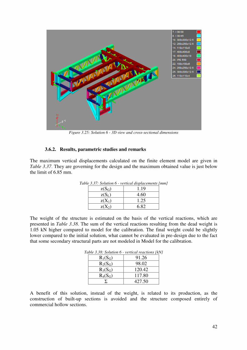
Figure 3.25: Solution 6
3.6.2. Results, parametric studies and remarks
The maximum vertical displacements calculated on the finite element model are given in Table 3.37. They are governing for the design and the maximum obtained value is just below the limit of 6.85 mm.
Table
The weight of the structure is estimated on the basis of the vertical reactions, whipresented in Table 3.38. The sum of the vertical reactions resulting 1.05 kN higher compared to model for the calibration.lower compared to the initial solution, what cannot be evaluated in prethat some secondary structural parts are not mod
Table
A benefit of this solution, instead of the weight, is construction of built-up sections is avoided and the structure composed entirely of commercial hollow sections.
: Solution 6 - 3D view and cross-sectional dimensions
Results, parametric studies and remarks
The maximum vertical displacements calculated on the finite element model are given in They are governing for the design and the maximum obtained value is just below
Table 3.37: Solution 6 - vertical displacements [mm]
z(SG) 1.19 z(SL) 4.60 z(X1) 1.25 z(X2) 6.82
The weight of the structure is estimated on the basis of the vertical reactions, whiThe sum of the vertical reactions resulting from the dead weight is
1.05 kN higher compared to model for the calibration. The final weight could be slightly lower compared to the initial solution, what cannot be evaluated in pre-design due to the fact that some secondary structural parts are not modeled in Model for the calibration.
Table 3.38: Solution 6 - vertical reactions [kN]
R1(SG) 91.26 R2(SG) 98.02 R3(SG) 120.42 R4(SG) 117.80
Σ 427.50
A benefit of this solution, instead of the weight, is related to its production, as the up sections is avoided and the structure composed entirely of
42
The maximum vertical displacements calculated on the finite element model are given in They are governing for the design and the maximum obtained value is just below
The weight of the structure is estimated on the basis of the vertical reactions, which are from the dead weight is
The final weight could be slightly design due to the fact
odel for the calibration.
related to its production, as the up sections is avoided and the structure composed entirely of

Table 3.39 shows the horizontal reactions resulting from load combination Xare in compliance with the designation given considerably lower than the values calculated on model for the calibration. Comparing the maximum horizontal reaction calculated here and the maximum value from model for the calibration, the difference is 98.86 kN what can positively influence design of the runway beams and reduce their cross-section properties.
Table 3.39
R1 R2 R3
353.72 289.51 222.10 In order to indicate the behavior values of elastic stresses (ULS) calculated in structural members and it is obvious that the ultimate limit states are not governing for the design. of the yield stress. Buckling resistance of mthe buckling reduction factors in the pre-design stage, although EN 1993The resistance is only slightly influenced by the instability, for instance, outbuckling of the chord reduces the resistance for 6%.
Table 3.40: Solution 6
Right/left side me
Right/left supporting beam
Connecting beam
Table
Cross-section
Lcr [mm]λ χ
Joints in this solution are mainly planar, except the jointperpendicular beams (see Figure 3.26
the chord. Planar joints can be regarded as an advantage from the manufacturing point of view and the design as well.
Figure 3.26: Joint at the int
shows the horizontal reactions resulting from load combination Xwith the designation given in Figure 2.19. Generally, the values are
considerably lower than the values calculated on model for the calibration. Comparing the maximum horizontal reaction calculated here and the maximum value from model for the
, the difference is 98.86 kN what can positively influence design of the runway section properties.
39: Solution 6 - horizontal reactions R(X2,ULS )[kN]
3 R4 R5 R6 222.10 187.26 -318.76 -235.35 -243.44
In order to indicate the behavior at the ultimate limit states, Table 3.40 presents the maximum values of elastic stresses (ULS) calculated in structural members and it is obvious that the ultimate limit states are not governing for the design. All stresses are in the range of 40
Buckling resistance of members in compression is assessed by calculating the buckling reduction factors in Table 3.41. As a buckling length the system length is used in
design stage, although EN 1993-1-1 allows a certain reduction for hollow sections. only slightly influenced by the instability, for instance, out
buckling of the chord reduces the resistance for 6%.
: Solution 6 - stress σ(X2,ULS), absolute values [MPa]
Right/left side member Chords 108.23 Braces 73.02
Right/left supporting Chords 79.26 Braces 74.51
Connecting beam Chords 98.30 Braces 125.63
Table 3.41: Solution 6 - Buckling reduction factor χ
Chord Diagonal brace section SHS 400x400x8 CHS 110x110x4
[mm] 6678 1778 42.00 41.34 0.94 0.94
Joints in this solution are mainly planar, except the joint at the intersectionFigure 3.26) where four diagonals and one vertical are connected to
the chord. Planar joints can be regarded as an advantage from the manufacturing point of
26: Joint at the intersection of the perpendicular beams
43
shows the horizontal reactions resulting from load combination X2 and the values . Generally, the values are
considerably lower than the values calculated on model for the calibration. Comparing the maximum horizontal reaction calculated here and the maximum value from model for the
, the difference is 98.86 kN what can positively influence design of the runway
R7 R8 243.44 -209.79
presents the maximum values of elastic stresses (ULS) calculated in structural members and it is obvious that the
All stresses are in the range of 40-50% embers in compression is assessed by calculating . As a buckling length the system length is used in 1 allows a certain reduction for hollow sections.
only slightly influenced by the instability, for instance, out-of-plane
the intersection between the ) where four diagonals and one vertical are connected to
the chord. Planar joints can be regarded as an advantage from the manufacturing point of
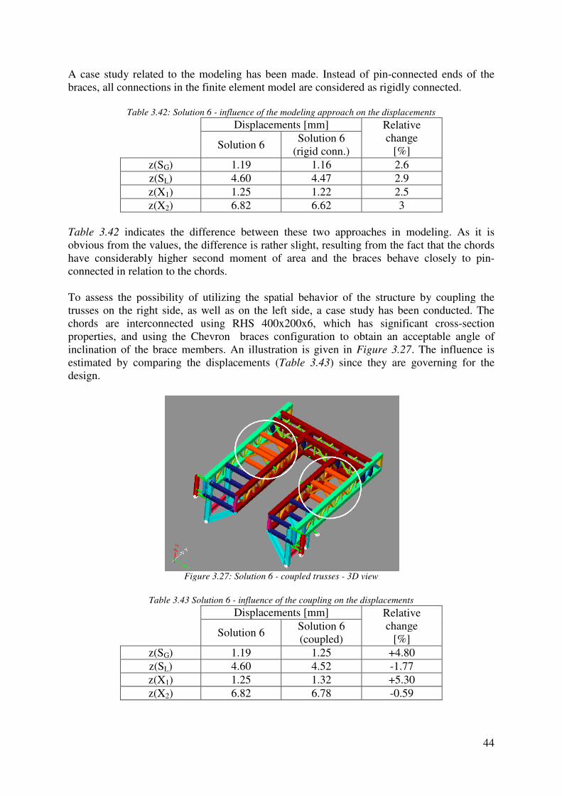
A case study related to the modeling has been made. braces, all connections in the finite element model are considered as rigidly connected.
Table 3.42: Solution 6
z(SG) z(SL) z(X1) z(X2)
Table 3.42 indicates the difference between these two approaches in modeling. As it is obvious from the values, the difference is rather slight, resulting from the fact that the chords have considerably higher second moment of area and the braces behave clconnected in relation to the chords. To assess the possibility of utilizing the spatial behavior of the structure by coupling the trusses on the right side, as well as on the left side, a case study has been conducted.chords are interconnected using RHS 400x200x6, which has significant crossproperties, and using the Chevron inclination of the brace members. An illustration is given estimated by comparing the displacements (design.
Figure
Table 3.43 Solution 6
z(SG) z(SL) z(X1) z(X2)
A case study related to the modeling has been made. Instead of pin-connected ends of the braces, all connections in the finite element model are considered as rigidly connected.
: Solution 6 - influence of the modeling approach on the displacements
Displacements [mm] Relative change
[%]Solution 6 Solution 6
(rigid conn.) 1.19 1.16 2.64.60 4.47 2.9 1.25 1.22 2.5 6.82 6.62 3
indicates the difference between these two approaches in modeling. As it is he difference is rather slight, resulting from the fact that the chords
have considerably higher second moment of area and the braces behave clconnected in relation to the chords.
To assess the possibility of utilizing the spatial behavior of the structure by coupling the trusses on the right side, as well as on the left side, a case study has been conducted.chords are interconnected using RHS 400x200x6, which has significant crossproperties, and using the Chevron braces configuration to obtain an acceptable angle of inclination of the brace members. An illustration is given in Figure 3.27
estimated by comparing the displacements (Table 3.43) since they are governing for the
Figure 3.27: Solution 6 - coupled trusses - 3D view
Solution 6 - influence of the coupling on the displacements
Displacements [mm] Relative change
[%]Solution 6
Solution 6 (coupled)
1.19 1.25 +4.804.60 4.52 -1.77 1.25 1.32 +5.306.82 6.78 -0.59
44
connected ends of the braces, all connections in the finite element model are considered as rigidly connected.
on the displacements
Relative change
[%] 2.6 2.9 2.5 3
indicates the difference between these two approaches in modeling. As it is he difference is rather slight, resulting from the fact that the chords
have considerably higher second moment of area and the braces behave closely to pin-
To assess the possibility of utilizing the spatial behavior of the structure by coupling the trusses on the right side, as well as on the left side, a case study has been conducted. The chords are interconnected using RHS 400x200x6, which has significant cross-section
braces configuration to obtain an acceptable angle of Figure 3.27. The influence is
) since they are governing for the
influence of the coupling on the displacements
Relative change
[%] +4.80 1.77
+5.30 0.59

Comparing the values resulting from load case Xmm what means that the coupling does not have any important influence on the overall behavior of the structure. On contrary, it increases the weight of theof the total weight). This inefficiency the carriage structure, the span between the coupled trusses is 3080 mm, the height is 1500 mm and the coupling truss is not stiff enouspan/height ratio.
3.7. Solution 7
3.7.1. General layout
The structure is a variant of Solution 6 with the main aim to simplify the production. Thelayout and cross-sections of the connecting beam remainwere proposed in Solution 6. Instead of the Warren trusses with verticals that are used in Solution 6, Vierendeel trusses are applied here for the side members and supporting beams. The application of Vierendeel trusses from verticals. To produce a vertical brace, a construction worker has to cut the section straightly, perpendicularly to its axis and to weld it to the chord by means of a filled weld all around the member. On the other hand, to produce a diagonal brace, which is part of a Warren truss, a worker has to perform bevelled cuts (one or double sided) and to weld it to the chord in an inclined position. structural members are subjected to the combined effects of axial forces, shear forces and bending moments and consequently it is more deformable. In a Warren truss with continuous chords, the chords are subjected to the combined effects of axial forces, shbending moments, while the braces are subjected to axial forces only. This may result in the heavier structure, but the increase of the weight can be compensated by simplification of the production and less labor costs. solution is given in Figure 3.28
Figure 3.28 for the dimensionsare inherited from Solution 6 and will not be repeated here.assuming rigid connections between members.
Figure 3.28: Solution 7
Comparing the values resulting from load case X2, the displacements are lower only for 0.04 mm what means that the coupling does not have any important influence on the overall behavior of the structure. On contrary, it increases the weight of the structure for 1.
This inefficiency results mainly from the geometry. On the right side of the carriage structure, the span between the coupled trusses is 3080 mm, the height is 1500 mm and the coupling truss is not stiff enough to redistribute the forces spatially for the given
General layout
is a variant of Solution 6 with the main aim to simplify the production. Thesections of the connecting beam remain the same in this solution as they
were proposed in Solution 6. Instead of the Warren trusses with verticals that are used in Solution 6, Vierendeel trusses are applied here for the side members and supporting beams. The application of Vierendeel trusses simplifies the production since the truss consists only from verticals. To produce a vertical brace, a construction worker has to cut the section straightly, perpendicularly to its axis and to weld it to the chord by means of a filled weld all
On the other hand, to produce a diagonal brace, which is part of a Warren truss, a worker has to perform bevelled cuts (one or double sided) and to weld it to the chord in an inclined position. A Vierendeel truss behaves as a frame, what means that all tructural members are subjected to the combined effects of axial forces, shear forces and
bending moments and consequently it is more deformable. In a Warren truss with continuous chords, the chords are subjected to the combined effects of axial forces, shbending moments, while the braces are subjected to axial forces only. This may result in the heavier structure, but the increase of the weight can be compensated by simplification of the production and less labor costs. A graphical representation of the structure proposed by this
Figure 3.28. The braces are composed of rectangular hollow sections (see for the dimensions as well). All other considerations related to the general layout
n 6 and will not be repeated here. The structure has been modeled assuming rigid connections between members.
: Solution 7 - 3D view and cross-sectional dimensions
45
, the displacements are lower only for 0.04 mm what means that the coupling does not have any important influence on the overall
structure for 1.63 t (6% On the right side of
the carriage structure, the span between the coupled trusses is 3080 mm, the height is 1500 gh to redistribute the forces spatially for the given
is a variant of Solution 6 with the main aim to simplify the production. The same in this solution as they
were proposed in Solution 6. Instead of the Warren trusses with verticals that are used in Solution 6, Vierendeel trusses are applied here for the side members and supporting beams.
fies the production since the truss consists only from verticals. To produce a vertical brace, a construction worker has to cut the section straightly, perpendicularly to its axis and to weld it to the chord by means of a filled weld all
On the other hand, to produce a diagonal brace, which is part of a Warren truss, a worker has to perform bevelled cuts (one or double sided) and to weld it to
A Vierendeel truss behaves as a frame, what means that all tructural members are subjected to the combined effects of axial forces, shear forces and
bending moments and consequently it is more deformable. In a Warren truss with continuous chords, the chords are subjected to the combined effects of axial forces, shear forces and bending moments, while the braces are subjected to axial forces only. This may result in the heavier structure, but the increase of the weight can be compensated by simplification of the
ation of the structure proposed by this races are composed of rectangular hollow sections (see ). All other considerations related to the general layout
The structure has been modeled

46
3.7.2. Results, parametric studies and remarks
The deflection criterion is governing for the design, thus the vertical displacements are the first task that has to be checked. The values are given in Table 3.44 and the maximum vertical displacement is lower than the limiting value (6.85 mm).
Table 3.44: Solution 7 - vertical displacements [mm]
z(SG) 1.22 z(SL) 4.52 z(X1) 1.28 z(X2) 6.74
The vertical reactions resulting from the dead weight are displayed in Table 3.45. Compared to Solution 6, the sum is 5.37 kN higher, what is slight increase and can be compensated by the simpler manufacturing.
Table 3.45: Solution 7 - vertical reactions [kN]
R1(SG) 93.17 R2(SG) 100.11 R3(SG) 120.93 R4(SG) 118.66
Σ 432.87 The values of the horizontal reactions are given in Table 3.46. Their range is similar to the range of values calculated in Solution 6 what is considerably lower than the values obtained in Model for the calibration and it can lead to the reduction of cross-section properties of the runway structure, which is not part of the detailed study.
Table 3.46: Solution 7 - horizontal reactions R(X2,ULS )[kN]
R1 R2 R3 R4 R5 R6 R7 R8 367.05 302.52 208.92 173.63 -342.95 -277.07 -222.37 -188.42
Table 3.47 is an overview of the maximum values of elastic stresses (ULS). As it is obvious, the elastic normal stress reaches 55% of the yield strength what means that the ultimate limit states are not governing for the design. Generally, braces in a Vierendeel truss should be designed as beam-columns because they are subjected to the combined action of axial forces and bending moments. In this case, their cross-sections were selected by the serviceability criterion, what results in quite stiff and stocky members. For the selected cross-sections of brace members and calculated buckling lengths (see Table 3.48) the buckling resistance check can be avoided according to EN 1993-1-1 because the relative slenderness is lower than 0.2.
Table 3.47: Solution 7 - stress σ(X2,ULS), absolute values [MPa]
Right/left side member Chords 98.00 Braces 88.41
Right/left supporting beam
Chords 113.48 Braces 105.89
Connecting beam Chords 98.15 Braces 128.55

Table
In
Lcr [mm] λ
λrel
A feasibility of this solution is strongly dependent on the assumption that all members are connected rigidly, which was used in the finite element model. In the case of hollow section joints, the above-mentioned assumption may not be appropriathrough a detailed study, for exampsection 450x250x8 mm is not considered by some producers as standard size and it may be difficult for the procurement. A case study related to the stiffness of certain openings and their influence on the overall behavior of the structure has been conducted. As it can be seen are present in some openings (at the intersections and next to the sustructure becomes notably softersupport is given in Figure 3.29
structure without the diagonals at the intersecsupport, an illustration is given
Figure 3.29: Solution 7 - structure without
diagonal next to the vertical support
Table 3.49: Solution 7 - influence of the diagonal next to the support on the displacements
z(SG) z(SL) z(X1) z(X2)
Table 3.48: Solution 7 - Buckling reduction factor χ
Brace (type 1) RHS 400x200x6
Brace (type 2)RHS 450x250x8
In-plane Out-of-plane
In-plane Out
1500 1500 1500 10.27 17.54 9.09 0.11 0.19 0.10
A feasibility of this solution is strongly dependent on the assumption that all members are connected rigidly, which was used in the finite element model. In the case of hollow section
mentioned assumption may not be appropriate and it detailed study, for example using the finite element approach. Rectangular hollow
section 450x250x8 mm is not considered by some producers as standard size and it may be
A case study related to the stiffness of certain openings and their influence on the overall behavior of the structure has been conducted. As it can be seen in Figure 3.28
some openings (at the intersections and next to the supports). Without them, the structure becomes notably softer. The structure without the diagonal next to the vertical
Figure 3.29 and the displacements are calculated in Table 7.49
structure without the diagonals at the intersections and the diagonal next to the vertical , an illustration is given in Figure 3.30 and the displacements are given
structure without the
diagonal next to the vertical support
Figure 3.30: Solution 7 - structure without the
diagonals at the intersections
influence of the diagonal next to the support on the displacements
Displacements [mm] Relative change
[%]Solution 7
Solution 7 (no diagonal at
the support) 1.22 1.40 14.754.52 4.86 7.52 1.28 1.47 14.846.74 7.32 8.61
47
Brace (type 2) RHS 450x250x8
Out-of-plane 1500 14.29 0.15
A feasibility of this solution is strongly dependent on the assumption that all members are connected rigidly, which was used in the finite element model. In the case of hollow section
it has to be proven Rectangular hollow
section 450x250x8 mm is not considered by some producers as standard size and it may be
A case study related to the stiffness of certain openings and their influence on the overall Figure 3.28, the diagonals
. Without them, the The structure without the diagonal next to the vertical
Table 7.49. For the nal next to the vertical
given in Table 3.50.
structure without the
diagonals at the intersections
influence of the diagonal next to the support on the displacements
Relative change
[%]
14.75 7.52
14.84 8.61
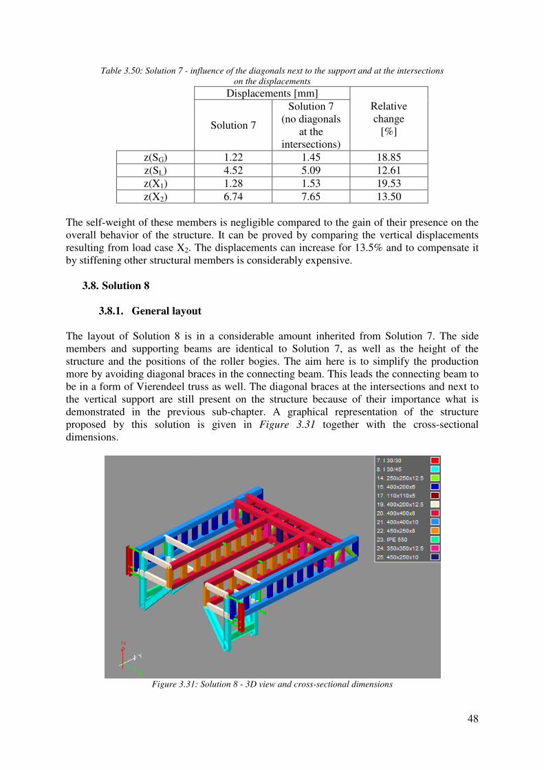
Table 3.50: Solution 7 - influence of the diagonals next to the support and at the intersections
z(SG) z(SL) z(X1) z(X2)
The self-weight of these members is negligible compared to the gain of their presence on the overall behavior of the structure. resulting from load case X2. The displacements by stiffening other structural members
3.8. Solution 8
3.8.1. General layout
The layout of Solution 8 is in a considerable amount inherited from Solution 7. The side members and supporting beams are identical to Solution 7, as well as the height of the structure and the positions of the roller bogies. The aim here is to simplify the production more by avoiding diagonal braces in the connecting beam. This leads the connecting beam to be in a form of Vierendeel truss as well. The diagonal braces at the intersections and next to the vertical support are still present on the structure because of their importancdemonstrated in the previous subproposed by this solution is given dimensions.
Figure 3.31:
influence of the diagonals next to the support and at the intersections
on the displacements
Displacements [mm] Relative change
[%]Solution 7
Solution 7 (no diagonals
at the intersections)
1.22 1.45 18.854.52 5.09 12.611.28 1.53 19.536.74 7.65 13.50
weight of these members is negligible compared to the gain of their presence on the overall behavior of the structure. It can be proved by comparing the vertical displacements
The displacements can increase for 13.5% and to compensate it other structural members is considerably expensive.
General layout
is in a considerable amount inherited from Solution 7. The side members and supporting beams are identical to Solution 7, as well as the height of the structure and the positions of the roller bogies. The aim here is to simplify the production
ding diagonal braces in the connecting beam. This leads the connecting beam to be in a form of Vierendeel truss as well. The diagonal braces at the intersections and next to the vertical support are still present on the structure because of their importanc
in the previous sub-chapter. A graphical representation of the structure proposed by this solution is given in Figure 3.31 together with the cross
: Solution 8 - 3D view and cross-sectional dimensions
48
influence of the diagonals next to the support and at the intersections
Relative change
[%]
18.85 12.61 19.53 13.50
weight of these members is negligible compared to the gain of their presence on the proved by comparing the vertical displacements
can increase for 13.5% and to compensate it
is in a considerable amount inherited from Solution 7. The side members and supporting beams are identical to Solution 7, as well as the height of the structure and the positions of the roller bogies. The aim here is to simplify the production
ding diagonal braces in the connecting beam. This leads the connecting beam to be in a form of Vierendeel truss as well. The diagonal braces at the intersections and next to the vertical support are still present on the structure because of their importance what is
A graphical representation of the structure together with the cross-sectional

49
3.8.2. Results, parametric studies and remarks
The deflections calculated for this solution are slightly higher than the resulting deflections in Solution 7 what is reasonable because the connecting beam has smaller stiffness here (a Vierendeel truss instead of a Warren truss with verticals). The values are given in Table 3.51 and they are below the limiting value of 6.85 mm.
Table 3.51: Solution 8 - vertical displacements [mm]
z(SG) 1.27 z(SL) 4.55 z(X1) 1.33 z(X2) 6.82
The vertical reactions resulting from the dead weight are given in Table 3.52. Compared to Model for the calibration, the sum of the vertical reactions is 14.9 kN higher and a compromise should be made by the manufacturer of the structure, between the enhanced weight and the simplified production.
Table 3.52: Solution 8 - vertical reactions [kN]
R1(SG) 97.20 R2(SG) 103.05 R3(SG) 121.74 R4(SG) 119.36
Σ 441.35 The horizontal reactions resulting from the load combination X2 are presented in Table 3.53. Their values are almost identical to the values calculated for Solution 7, and the same benefit is applicable here (possible reduction of cross-section properties of the runway structure).
Table 3.53: Solution 8 - horizontal reactions R(X2,ULS )[kN]
R1 R2 R3 R4 R5 R6 R7 R8 369.71 305.80 209.09 173.41 -344.75 -279.04 -223.88 -190.00
In order to indicate the behavior at the ultimate limit states, the maximum values of elastic stresses (ULS) calculated in structural members are given in Table 3.54. All stresses are in the range of 40-50% of the yield stress and as a result, the ultimate limit states are not governing for the design. The brace members are stocky, hence they are not susceptible to stability problems (the relative slenderness is lower than 0.2).
Table 3.54: Solution 8 - stress σ(X2,ULS), absolute values [MPa]
Right/left side member Chords 95.33 Braces 90.92
Right/left supporting beam
Chords 114.24 Braces 107.09
Connecting beam Chords 107.46 Braces 93.69
A feasibility of Solution 8 is mostly dependent on the assumption that all members are connected rigidly, what may be questionable in the case of hollow section joints. The stiffness of joints has to be proven through a detailed study in order to verify the assumption.

A case study showing the influence ofconducted. The layout is given displacements are presented in 400x200x12.5 mm.
Figure 3.32
Table 3.55: Solution 8
z(SG) z(SL) z(X1) z(X2)
The influence of the coupling is negligible, as it can be seen from the displacements. The vertical displacements resulting from load case Xweight is increased for 2.36 t from the span/height ratio as it was described for Solution 6.
3.9. Overall comparison and selection of
This sub-chapter will summarize all considerations chapters. A comparison will be made regarding the deflectionsreactions (Table 3.57), weight of the structure3.58). All proposed solutions were arranged in terms of the structural systemselected cross-sections to satisfy the deflection criterion of 6.85 mm, therefore the vertical displacements in each solution are either equal to the limit or slightly below it. As it is given in Table 3.56, the values are between 6.74 mm and 6.85 mmother values occur in the structure as a consequence of this criterion.
A case study showing the influence of coupling the trusses on the right and left side has been conducted. The layout is given in Figure 3.32 and the maximum values of the vertical displacements are presented in Table 3.55. The beams are connected using RHS
32: Solution 8 - coupled Vierendeel trusses - 3D view
Solution 8 - influence of the coupling on the displacements
Displacements [mm] Relative chang
[%]Solution 8 Solution 8 (coupled)
1.27 1.35 +5.934.55 4.40 -3.401.33 1.41 +5.676.82 6.72 -1.49
The influence of the coupling is negligible, as it can be seen from the displacements. The
resulting from load case X2 are lower only for 0.1 mm while the weight is increased for 2.36 t (8% of the total weight). The non-efficiency results mainly from the span/height ratio as it was described for Solution 6.
Overall comparison and selection of the solution for the detailed design
chapter will summarize all considerations that were explained in previous subchapters. A comparison will be made regarding the deflections (Table 3.56
, weight of the structure (Table 3.57) and horizontal reactions
All proposed solutions were arranged in terms of the structural systemsections to satisfy the deflection criterion of 6.85 mm, therefore the vertical
ch solution are either equal to the limit or slightly below it. As it is given , the values are between 6.74 mm and 6.85 mm (load combination X
other values occur in the structure as a consequence of this criterion.
50
coupling the trusses on the right and left side has been and the maximum values of the vertical The beams are connected using RHS
influence of the coupling on the displacements
Relative change
[%] 5.93 3.40
67 1.49
The influence of the coupling is negligible, as it can be seen from the displacements. The are lower only for 0.1 mm while the
efficiency results mainly
the solution for the detailed design
explained in previous sub-Table 3.56), vertical
and horizontal reactions (Table
All proposed solutions were arranged in terms of the structural system, dimensions and sections to satisfy the deflection criterion of 6.85 mm, therefore the vertical
ch solution are either equal to the limit or slightly below it. As it is given (load combination X2) . All
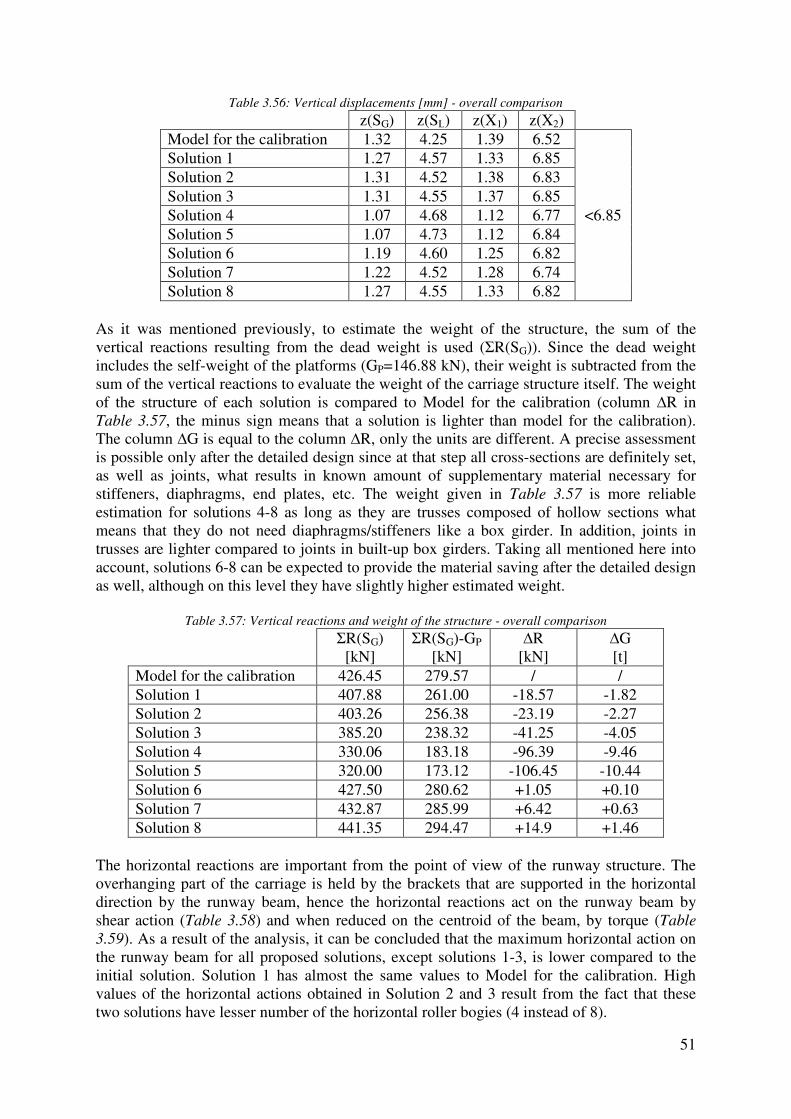
51
Table 3.56: Vertical displacements [mm] - overall comparison
z(SG) z(SL) z(X1) z(X2) Model for the calibration 1.32 4.25 1.39 6.52
<6.85
Solution 1 1.27 4.57 1.33 6.85 Solution 2 1.31 4.52 1.38 6.83 Solution 3 1.31 4.55 1.37 6.85 Solution 4 1.07 4.68 1.12 6.77 Solution 5 1.07 4.73 1.12 6.84 Solution 6 1.19 4.60 1.25 6.82 Solution 7 1.22 4.52 1.28 6.74 Solution 8 1.27 4.55 1.33 6.82
As it was mentioned previously, to estimate the weight of the structure, the sum of the vertical reactions resulting from the dead weight is used (ΣR(SG)). Since the dead weight includes the self-weight of the platforms (GP=146.88 kN), their weight is subtracted from the sum of the vertical reactions to evaluate the weight of the carriage structure itself. The weight of the structure of each solution is compared to Model for the calibration (column ∆R in Table 3.57, the minus sign means that a solution is lighter than model for the calibration). The column ∆G is equal to the column ∆R, only the units are different. A precise assessment is possible only after the detailed design since at that step all cross-sections are definitely set, as well as joints, what results in known amount of supplementary material necessary for stiffeners, diaphragms, end plates, etc. The weight given in Table 3.57 is more reliable estimation for solutions 4-8 as long as they are trusses composed of hollow sections what means that they do not need diaphragms/stiffeners like a box girder. In addition, joints in trusses are lighter compared to joints in built-up box girders. Taking all mentioned here into account, solutions 6-8 can be expected to provide the material saving after the detailed design as well, although on this level they have slightly higher estimated weight.
Table 3.57: Vertical reactions and weight of the structure - overall comparison
ΣR(SG) [kN]
ΣR(SG)-GP
[kN] ∆R
[kN] ∆G [t]
Model for the calibration 426.45 279.57 / / Solution 1 407.88 261.00 -18.57 -1.82 Solution 2 403.26 256.38 -23.19 -2.27 Solution 3 385.20 238.32 -41.25 -4.05 Solution 4 330.06 183.18 -96.39 -9.46 Solution 5 320.00 173.12 -106.45 -10.44 Solution 6 427.50 280.62 +1.05 +0.10 Solution 7 432.87 285.99 +6.42 +0.63 Solution 8 441.35 294.47 +14.9 +1.46
The horizontal reactions are important from the point of view of the runway structure. The overhanging part of the carriage is held by the brackets that are supported in the horizontal direction by the runway beam, hence the horizontal reactions act on the runway beam by shear action (Table 3.58) and when reduced on the centroid of the beam, by torque (Table
3.59). As a result of the analysis, it can be concluded that the maximum horizontal action on the runway beam for all proposed solutions, except solutions 1-3, is lower compared to the initial solution. Solution 1 has almost the same values to Model for the calibration. High values of the horizontal actions obtained in Solution 2 and 3 result from the fact that these two solutions have lesser number of the horizontal roller bogies (4 instead of 8).
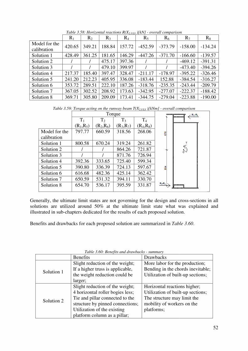
Table 3.58: Horizo
R1 RModel for the calibration
420.65 349.21
Solution 1 428.49 361.25Solution 2 / /Solution 3 / /Solution 4 217.37 185.40Solution 5 241.20 212.23Solution 6 353.72 289.51Solution 7 367.05 302.52Solution 8 369.71 305.80
Table 3.59: Torque acting on the runway beam T(X
T1
(R1,R5) Model for the calibration
797.77
Solution 1 800.58 Solution 2 / Solution 3 / Solution 4 392.36 Solution 5 390.80 Solution 6 616.68 Solution 7 650.59 Solution 8 654.70
Generally, the ultimate limit states are not governing for the design and crosssolutions are utilized around 5illustrated in sub-chapters dedicated for the results of each proposed solution. Benefits and drawbacks for each proposed solution are summarized in
Table
Benefits
Solution 1
Slight reduction of the weightIf a higher truss is the weight reduction could be larger;
Solution 2
Slight reduction of the weight4 horizontal roller bogies lessTie and pillar connected to thstructure by pinned connectionsUtilization of the existing platform column as a pillar
: Horizontal reactions R(X2,ULS )[kN] - overall comparison
R2 R3 R4 R5 R6
349.21 188.84 157.72 -452.59 -373.79
361.25 181.65 146.29 -447.26 -371.70 / 475.17 397.36 / / / 479.10 399.97 / /
185.40 397.47 328.47 -211.17 -178.97 212.23 405.95 336.08 -183.44 152.88 289.51 222.10 187.26 -318.76 -235.35 302.52 208.92 173.63 -342.95 -277.07 305.80 209.09 173.41 -344.75 -279.04
Torque acting on the runway beam T(X2,ULS )[kNm] - overall comparison
Torque
T2
(R2,R6) T3
(R3,R7) T4
(R4,R8) 660.59 318.56 268.06
670.24 319.24 261.82 / 864.26 721.87 / 871.76 726.94
333.65 725.40 599.34 336.39 724.13 597.67 482.36 425.14 362.42 531.32 394.11 330.70 536.17 395.59 331.87
ultimate limit states are not governing for the design and crosssolutions are utilized around 50% at the ultimate limit state what was explained and
chapters dedicated for the results of each proposed solution.
and drawbacks for each proposed solution are summarized in Table 3.60
Table 3.60: Benefits and drawbacks - summary
Benefits Drawbacks Slight reduction of the weight; If a higher truss is applicable, the weight reduction could be
More labor for the productionBending in the chords inevitableUtilization of built
Slight reduction of the weight; 4 horizontal roller bogies less; Tie and pillar connected to the structure by pinned connections; Utilization of the existing platform column as a pillar;
Horizontal reactions higherUtilization of builtThe structure may limit the mobility of workers on the platforms;
52
overall comparison
R7 R8
-158.00 -134.24
-166.60 -139.57 -469.12 -391.31 -473.40 -394.26 -395.22 -326.46 -384.54 -316.27 -243.44 -209.79 -222.37 -188.42 -223.88 -190.00
overall comparison
ultimate limit states are not governing for the design and cross-sections in all 0% at the ultimate limit state what was explained and
chapters dedicated for the results of each proposed solution.
Table 3.60.
More labor for the production; chords inevitable; uilt-up sections;
Horizontal reactions higher; Utilization of built-up sections; The structure may limit the mobility of workers on the

53
Solution 3
Reduction of the weight around 10%; 4 horizontal roller bogies less; Tie and pillar connected to the structure by pinned connections;
Horizontal reactions higher; Utilization of the existing platform column as a pillar is not possible; Utilization of built-up sections; The structure may limit the mobility of workers on the platforms;
Solution 4
Significant reduction of the weight; Lower horizontal reactions; Utilization of commercial hollow sections;
More labor for the production; Very complex details and joints;
Solution 5
The lightest structure among proposed solutions; Lower horizontal reactions; Smaller number of members compared to Solution 4; Utilization of commercial hollow sections;
More labor for the production; Very complex details and joints; An additional member (stiff) necessary to support the horizontal roller bogie;
Solution 6
Utilization of commercial hollow sections; Smaller horizontal reactions Pinned joints;
More labor for the production;
Solution 7
Utilization of commercial hollow sections; Smaller horizontal reactions; Diagonal braces partly avoided;
Stiffness of joints is questionable;
Solution 8
Utilization of commercial hollow sections; Smaller horizontal reactions; Diagonal braces completely avoided;
Increase of the weight of the structure; Stiffness of joints is questionable;
To summarize, the two main aspects figuring in these pre-design studies and defining the final cost are the weight of the structure and the amount of labor needed to fabricate it. All these solutions can be classified in groups based on the similarities among them (see Table
3.61, Table 3.62 and Table 3.63).
Table 3.61: Group A of the pre-design solutions
Group Criterion Solution Fabrication complexity
Material saving
A
Layout similar to the initial solution with some improvements, built-up box sections.
Solution 1 Solution 2 Solution 3
Medium Low to medium

54
Table 3.62: Group B of the pre-design solutions
Group Criterion Solution Fabrication complexity
Material saving
B Box trusses composed of hollow sections.
Solution 4 Solution 5
Very high High
Table 3.63: Group C of the pre-design solutions
Group Criterion Solution Fabrication complexity
Material saving
C Planar trusses composed of hollow sections.
Solution 6 Solution 7 Solution 8
Medium Low to medium
After presenting all above-mentioned facts related to the proposed solutions, the representatives from DREVER International selected Solution 6 to be studied in detail. The main reason for selecting Solution 6 is related to the fabrication. The company strongly prefers to use commercial sections instead of built-up sections mainly because of the fabrication tolerances what is sometimes rather difficult to be satisfied in the workshop where this structure is intended to be manufactured, therefore Group A was discarded. Solutions from Group B were not selected because of their fabrication complexity. Within Group C, Solution 6 was preferred as long as it provides higher material saving compared to Solution 7 and Solution 8. An additional reason is that the assumption related to joints (joints considered as fully rigid) in Solution 7 and Solution 8 may be questionable. Upon a suggestion of the representatives from DREVER International, two variants of Solution 6 will be studied in detail:
- Solution 6-1: Welded solution made completely of hollow sections - Solution 6-2: Bolted solution made of hollow section chords and angles as braces
4. Detailed design of the selected solutions
4.1. Welded solution made completely of hollow sections (Solution 6-1)
4.1.1. Improvements and final layout of the structure
This chapter will present the final layout of the structure that is improved after the detailed study of the pre-design proposal. The methodology used during the design will be explained in the following sub-chapters and the computation details can be found in Annex A. The main goals for the improvements were to:
- Decrease the number of braces - Avoid vertical brace members as much as possible - Simplify joints
Firstly, the finite element model has been improved by introducing load cases X3 and X4 and all possible load combinations. The pre-design stage included only X1 and X2 for the sake of simplicity. In the design stage, the region around the brackets and horizontal supports is modeled more precisely.
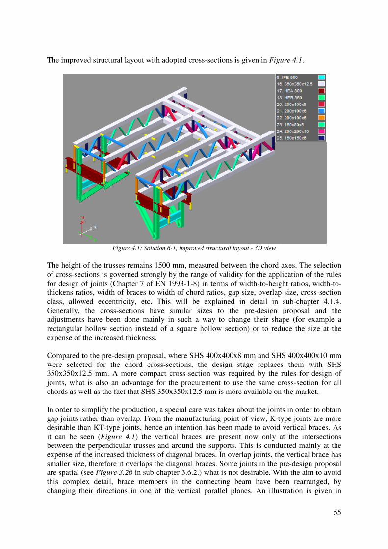
The improved structural layout with adopted cross
Figure 4.1: Solution 6
The height of the trusses remains 1500 mm, measured between the chord axes. of cross-sections is governed strongly by the range of validity for the application of for design of joints (Chapter 7 of EN 1993thickens ratios, width of braces to width of chord rclass, allowed eccentricity, etc. This will be explained in detail in Generally, the cross-sections have similar sizes to the preadjustments have been done mainly in srectangular hollow section instead of a square hollow section) or to reduce the size at the expense of the increased thickness. Compared to the pre-design proposal, where SHS 400x400x8 mm and SHS 400x400x10 were selected for the chord cross350x350x12.5 mm. A more compact crossjoints, what is also an advantage for the procurement to use the same crosschords as well as the fact that SHS 350x350x12.5 mm is more available on the market. In order to simplify the production, a special care was taken about the joints in order to obtain gap joints rather than overlap. desirable than KT-type joints, hence an intention has been made to avoid vertical braces. As it can be seen (Figure 4.1) the vertical braces are present now only between the perpendicular trusses and arounexpense of the increased thickness of diagonal braces. smaller size, therefore it overlaps the diagonal braces. are spatial (see Figure 3.26 in subthis complex detail, brace members in the connecting beam have been rearranged, by changing their directions in one of the vertical parallel planes. An illustration is given
The improved structural layout with adopted cross-sections is given in Figure 4.1
: Solution 6-1, improved structural layout - 3D view
remains 1500 mm, measured between the chord axes.
sections is governed strongly by the range of validity for the application of for design of joints (Chapter 7 of EN 1993-1-8) in terms of width-to-height ratios, widththickens ratios, width of braces to width of chord ratios, gap size, overlap size,
allowed eccentricity, etc. This will be explained in detail in sections have similar sizes to the pre-design proposal and the
adjustments have been done mainly in such a way to change their shape (for example a rectangular hollow section instead of a square hollow section) or to reduce the size at the expense of the increased thickness.
design proposal, where SHS 400x400x8 mm and SHS 400x400x10 were selected for the chord cross-sections, the design stage replaces them with SHS 350x350x12.5 mm. A more compact cross-section was required by the rules for design of joints, what is also an advantage for the procurement to use the same crosschords as well as the fact that SHS 350x350x12.5 mm is more available on the market.
In order to simplify the production, a special care was taken about the joints in order to obtain gap joints rather than overlap. From the manufacturing point of view, K-type joints are more
type joints, hence an intention has been made to avoid vertical braces. As ) the vertical braces are present now only at
between the perpendicular trusses and around the supports. This is conducted mainly at the expense of the increased thickness of diagonal braces. In overlap joints, the vertical brace has smaller size, therefore it overlaps the diagonal braces. Some joints in the pre
in sub-chapter 3.6.2.) what is not desirable. With the aim to avoid this complex detail, brace members in the connecting beam have been rearranged, by changing their directions in one of the vertical parallel planes. An illustration is given
55
Figure 4.1.
remains 1500 mm, measured between the chord axes. The selection sections is governed strongly by the range of validity for the application of the rules
height ratios, width-to-, gap size, overlap size, cross-section
allowed eccentricity, etc. This will be explained in detail in sub-chapter 4.1.4. design proposal and the
uch a way to change their shape (for example a rectangular hollow section instead of a square hollow section) or to reduce the size at the
design proposal, where SHS 400x400x8 mm and SHS 400x400x10 mm sections, the design stage replaces them with SHS
section was required by the rules for design of joints, what is also an advantage for the procurement to use the same cross-section for all chords as well as the fact that SHS 350x350x12.5 mm is more available on the market.
In order to simplify the production, a special care was taken about the joints in order to obtain type joints are more
type joints, hence an intention has been made to avoid vertical braces. As at the intersections
d the supports. This is conducted mainly at the In overlap joints, the vertical brace has Some joints in the pre-design proposal
what is not desirable. With the aim to avoid this complex detail, brace members in the connecting beam have been rearranged, by changing their directions in one of the vertical parallel planes. An illustration is given in
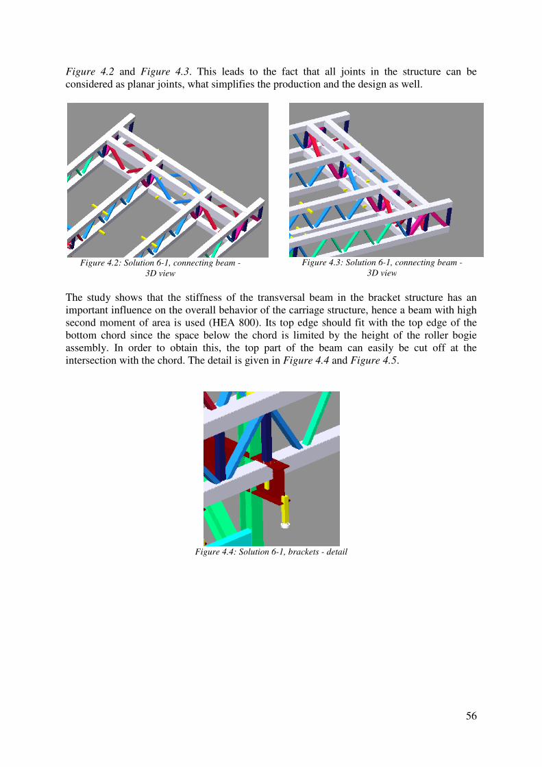
Figure 4.2 and Figure 4.3. considered as planar joints, what simplifies the production and the design as well.
Figure 4.2: Solution 6-1, connecting beam
3D view
The study shows that the stiffness of the transversal bimportant influence on the overall behavior of the carriage structure, hence a beam with high second moment of area is used (HEA 800). Its top edge should fit with the top edge of the bottom chord since the space below tassembly. In order to obtain this, the top part of the beam can easily be cut off at the intersection with the chord. Th
Figure
This leads to the fact that all joints in the structure canconsidered as planar joints, what simplifies the production and the design as well.
1, connecting beam - Figure 4.3: Solution 6-1, connecting beam
3D view
The study shows that the stiffness of the transversal beam in the bracket structure has an important influence on the overall behavior of the carriage structure, hence a beam with high second moment of area is used (HEA 800). Its top edge should fit with the top edge of the
chord since the space below the chord is limited by the height of the roller bogie assembly. In order to obtain this, the top part of the beam can easily be cut off at the
The detail is given in Figure 4.4 and Figure 4.5
Figure 4.4: Solution 6-1, brackets - detail
56
This leads to the fact that all joints in the structure can be considered as planar joints, what simplifies the production and the design as well.
1, connecting beam -
3D view
eam in the bracket structure has an important influence on the overall behavior of the carriage structure, hence a beam with high second moment of area is used (HEA 800). Its top edge should fit with the top edge of the
he chord is limited by the height of the roller bogie assembly. In order to obtain this, the top part of the beam can easily be cut off at the
Figure 4.5.

Figure
4.1.2. Serviceability limit states
Although the computation details can be found in Anchecks are presented here because displacements calculated in the finite element model are compared with6.85 mm as it was already used in prpresented in Table 4.1 and an illustration of the deformed shapegiven in Figure 4.6.
Table
Figure 4.6: Solution 6
Figure 4.5: Solution 6-1, brackets - detail
Serviceability limit states
Although the computation details can be found in Annex A, the serviceability limit state are presented here because they are governing for the design in this case.
displacements calculated in the finite element model are compared with the limiting value of 6.85 mm as it was already used in pre-design (see sub-chapter 2.6). The maximum values are
n illustration of the deformed shape for load combination X
Table 4.1: Solution 6-1, vertical displacements [mm]
z(X1) 1.28
≤6.85 z(X2) 6.83 z(X3) 6.85 z(X4) 6.81
: Solution 6-1, deformed model for load combination X3
57
the serviceability limit state in this case. The vertical
the limiting value of The maximum values are
for load combination X3 is
3
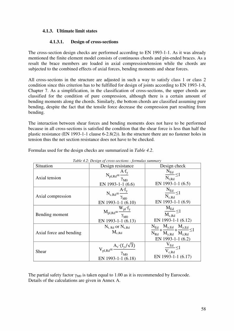
58
4.1.3. Ultimate limit states
4.1.3.1. Design of cross-sections
The cross-section design checks are performed according to EN 1993-1-1. As it was already mentioned the finite element model consists of continuous chords and pin-ended braces. As a result the brace members are loaded in axial compression/tension while the chords are subjected to the combined effects of axial forces, bending moments and shear forces. All cross-sections in the structure are adjusted in such a way to satisfy class 1 or class 2 condition since this criterion has to be fulfilled for design of joints according to EN 1993-1-8, Chapter 7. As a simplification, in the classification of cross-sections, the upper chords are classified for the condition of pure compression, although there is a certain amount of bending moments along the chords. Similarly, the bottom chords are classified assuming pure bending, despite the fact that the tensile force decrease the compression part resulting from bending. The interaction between shear forces and bending moments does not have to be performed because in all cross-sections is satisfied the condition that the shear force is less than half the plastic resistance (EN 1993-1-1 clause 6-2.8(2)). In the structure there are no fastener holes in tension thus the net section resistance does not have to be checked.
Formulas used for the design checks are summarized in Table 4.2.
Table 4.2: Design of cross-sections - formulas summary
Situation Design resistance Design check
Axial tension Npl,Rd=
A·fy
γM0
EN 1993-1-1 (6.6)
NEd
Nt,Rd≤1
EN 1993-1-1 (6.5)
Axial compression Nc,Rd=
A·fy
γM0
EN 1993-1-1 (6.10)
NEd
Nc,Rd≤1
EN 1993-1-1 (6.9)
Bending moment Mpl,Rd=
Wpl·fy
γM0
EN 1993-1-1 (6.13)
MEd
Mc,Rd≤1
EN 1993-1-1 (6.12)
Axial force and bending Nt, Rd or Nc,Rd
Mc,Rd NEd
NRd+
My,Ed
My,Rd+
Mz,Ed
Mz,Rd≤1
EN 1993-1-1 (6.2)
Shear Vpl,Rd=Av·(fy/√3)
γM0
EN 1993-1-1 (6.18)
VEd
Vc,Rd≤1
EN 1993-1-1 (6.17)
The partial safety factor γM0 is taken equal to 1.00 as it is recommended by Eurocode. Details of the calculations are given in Annex A.
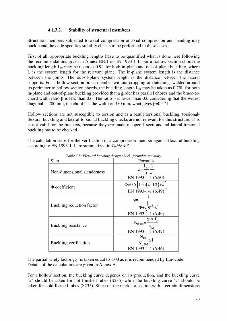
59
4.1.3.2. Stability of structural members
Structural members subjected to axial compression or axial compression and bending may buckle and the code specifies stability checks to be performed in these cases. First of all, appropriate buckling lengths have to be quantified what is done here following the recommendations given in Annex BB.1 of EN 1993-1-1. For a hollow section chord the buckling length Lcr may be taken as 0.9L for both in-plane and out-of-plane buckling, where L is the system length for the relevant plane. The in-plane system length is the distance between the joints. The out-of-plane system length is the distance between the lateral supports. For a hollow section brace member without cropping or flattening, welded around its perimeter to hollow section chords, the buckling length Lcr may be taken as 0.75L for both in-plane and out-of-plane buckling provided that a girder has parallel chords and the brace-to-chord width ratio β is less than 0.6. The ratio β is lower than 0.6 considering that the widest diagonal is 200 mm, the chord has the width of 350 mm, what gives β=0.571. Hollow sections are not susceptible to torsion and as a result torsional buckling, torsional-flexural buckling and lateral-torsional buckling checks are not relevant for this structure. This is not valid for the brackets, because they are made of open I sections and lateral-torsional buckling has to be checked. The calculation steps for the verification of a compression member against flexural buckling according to EN 1993-1-1 are summarized in Table 4.3.
Table 4.3: Flexural buckling design check- formulas summary
Step Formula
Non-dimensional slenderness λ�=
Lcr
i
1
λ1
EN 1993-1-1 (6.50)
Φ coefficient Φ=0.5 �1+α�λ�-0.2�+λ�2�
EN 1993-1-1 (6.49)
Buckling reduction factor χ=
1
Φ+�Φ2-λ�2
EN 1993-1-1 (6.49)
Buckling resistance Nb,Rd=
χ·A·fy
γM1
EN 1993-1-1 (6.47)
Buckling verification NEd
Nb,Rd≤1
EN 1993-1-1 (6.46) The partial safety factor γM1 is taken equal to 1.00 as it is recommended by Eurocode. Details of the calculations are given in Annex A. For a hollow section, the buckling curve depends on its production, and the buckling curve "a" should be taken for hot finished tubes (S235) while the buckling curve "c" should be taken for cold formed tubes (S235). Since on the market a section with a certain dimensions

60
can be found both as hot finished or cold formed, the buckling curve "c" is selected because the imperfection factor α is higher for cold formed (assumption on the safe side). It should also be stated here that the equations for the design buckling resistance of a member given in EN 1993-1-1 were derived with the assumption that a member is loaded by constant axial compression force along its length. For the structure under the study, this complies for the case of in-plane buckling of the chord. In the case of out-of-plane buckling, the axial force varies between the lateral supports along the chord of the structure. As a simplification, taking into account the fact that the ultimate limit states are not governing criterion for the design, it is assumed that the axial force is constant between the lateral supports with its maximum value. Moreover, in-plane buckling of the chord has to be calculated only for the connecting beam, coming from the reason that the non-dimensional slenderness for chords of the side members and supporting beams is less than 0.2 and the buckling effects may be ignored according to EN 1993-1-1 clause 6.3.1.2(4). Chords in this structure are subjected to the combined effects of bending (around the major axis) and axial forces, thus they have to satisfy the equations presented in Table 4.4.
Table 4.4: Stability of members loaded in bending and axial compression- formulas summary
Design resistance Design check
NRk=A·fy
MRk=Wpl,y·fy
EN 1993-1-1 (Table 6.7)
NEd
χyNRk
γM1
+kyy
My,Ed
χLT
My,Rk
γM1
≤1
EN 1993-1-1 (6.61)
NRk=A·fy MRk=Wpl,y·fy
EN 1993-1-1 (Table 6.7)
NEd
χzNRk
γM1
+kzy
My,Ed
χLT
My,Rk
γM1
≤1
EN 1993-1-1 (6.62) Hollow sections are not susceptible to torsional deformation, hence χLT=1. Generally, the interaction factors kyy and kzy may be obtained using two methods given in EN 1993-1-1. For this structure, the factors are obtained from Annex B of EN 1993-1-1 (alternative method 2) since the method is applicable for hollow sections and at the same time faster to apply. According to Annex B of EN 1993-1-1, the coefficient kzy may be taken equal to zero for hollow sections under axial compression and uniaxial bending My,Ed. Considering all above-mentioned facts, the design checks for a beam-column (Table 4.4) become simplified and they are given in Table 4.5. As it can be seen, according to the applied method, for rectangular hollow sections there is no need for combining out-of-plane buckling and in-plane bending moments (uniaxial bending).
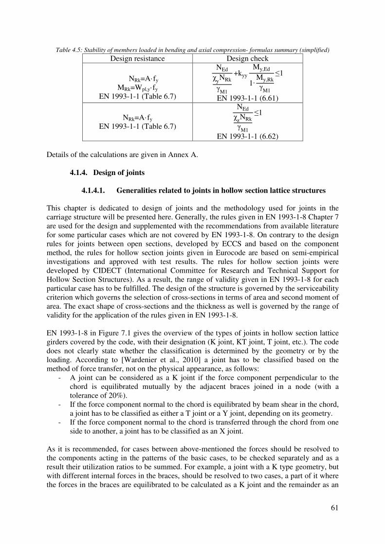
61
Table 4.5: Stability of members loaded in bending and axial compression- formulas summary (simplified)
Design resistance Design check
NRk=A·fy
MRk=Wpl,y·fy
EN 1993-1-1 (Table 6.7)
NEd
χyNRk
γM1
+kyy
My,Ed
1·My,Rk
γM1
≤1
EN 1993-1-1 (6.61)
NRk=A·fy
EN 1993-1-1 (Table 6.7)
NEd
χzNRk
γM1
≤1
EN 1993-1-1 (6.62) Details of the calculations are given in Annex A.
4.1.4. Design of joints
4.1.4.1. Generalities related to joints in hollow section lattice structures
This chapter is dedicated to design of joints and the methodology used for joints in the carriage structure will be presented here. Generally, the rules given in EN 1993-1-8 Chapter 7 are used for the design and supplemented with the recommendations from available literature for some particular cases which are not covered by EN 1993-1-8. On contrary to the design rules for joints between open sections, developed by ECCS and based on the component method, the rules for hollow section joints given in Eurocode are based on semi-empirical investigations and approved with test results. The rules for hollow section joints were developed by CIDECT (International Committee for Research and Technical Support for Hollow Section Structures). As a result, the range of validity given in EN 1993-1-8 for each particular case has to be fulfilled. The design of the structure is governed by the serviceability criterion which governs the selection of cross-sections in terms of area and second moment of area. The exact shape of cross-sections and the thickness as well is governed by the range of validity for the application of the rules given in EN 1993-1-8. EN 1993-1-8 in Figure 7.1 gives the overview of the types of joints in hollow section lattice girders covered by the code, with their designation (K joint, KT joint, T joint, etc.). The code does not clearly state whether the classification is determined by the geometry or by the loading. According to [Wardenier et al., 2010] a joint has to be classified based on the method of force transfer, not on the physical appearance, as follows:
- A joint can be considered as a K joint if the force component perpendicular to the chord is equilibrated mutually by the adjacent braces joined in a node (with a tolerance of 20%).
- If the force component normal to the chord is equilibrated by beam shear in the chord, a joint has to be classified as either a T joint or a Y joint, depending on its geometry.
- If the force component normal to the chord is transferred through the chord from one side to another, a joint has to be classified as an X joint.
As it is recommended, for cases between above-mentioned the forces should be resolved to the components acting in the patterns of the basic cases, to be checked separately and as a result their utilization ratios to be summed. For example, a joint with a K type geometry, but with different internal forces in the braces, should be resolved to two cases, a part of it where the forces in the braces are equilibrated to be calculated as a K joint and the remainder as an

Y joint and finally their utilization ratios to be summed up. joints calculated in Annex A and as an overview the final values member) are given in Table 4.6
only as a K type. The axial force in brace member SM3 is 2.5 times higher than the force in brace member SM2.
Table 4.6: Influence of the classification on the design
Calculated according to the geometry
Applied equations for the resistance of a K type joint
NSM2,Ed
NSM2,Rd
=83.04
706.9=
NSM3,Ed
NSM3,Rd
=213.10
677.40
Although the utilization ratios are small in this case, the difference in the results is obvious. For the joint calculated without consideriratio is 31.45% and with considering the method of force transfer the utilization ratio is 46.21%. It should be mentioned that the design resistance of the weld connecting the braces to the chord, stated by clause 7.3.1(4) of EN 1993of the cross-sections of those braces in order to allow for nonsufficient deformation capacity to allow for redistribution of bending momeconcept of full strength fillet weld and the derivation of full strength throat thickness for double fillet end welds given in for the throat thickness of a single fillet weld case of hollow section joints. The design resistance of a fillet weld, given in EN 1993
�where: fu is the nominal ultimate tensile strength of the weaker part joinedβw is the appropriate correlation factor (
Y joint and finally their utilization ratios to be summed up. This approach is applied on the joints calculated in Annex A and as an overview the final values for joint 2 (right/left side
Table 4.6 with comparison to the case where the joint is calculated only as a K type. The axial force in brace member SM3 is 2.5 times higher than the force in
: Influence of the classification on the design checks of joints
Calculated according to the geometry Calculated according to the
Applied equations for the resistance of Applied equations for the resistance of a K type and an Y type joint
=0.1175
10
40=0.3145
NSM2,Ed
NSM2,Rd
=83.04
706.9=0.1175
NSM3,Ed
NSM3,Rd
=83.04
677.40+
133.06
391.80
Although the utilization ratios are small in this case, the difference in the results is obvious. For the joint calculated without considering the ratio between the axial forces the utilization ratio is 31.45% and with considering the method of force transfer the utilization ratio is
It should be mentioned that the design resistance of the weld connecting the braces to the ed by clause 7.3.1(4) of EN 1993-1-8, should not be less that the design resistance
sections of those braces in order to allow for non-uniform stresssufficient deformation capacity to allow for redistribution of bending momeconcept of full strength fillet weld and the derivation of full strength throat thickness for double fillet end welds given in [Jaspart and Weynand, 2016], a derivation will be done here for the throat thickness of a single fillet weld (see Figure 4.7) which has to be applied in the
The design resistance of a fillet weld, given in EN 1993-1-8 (equation 4.1) is:
�σ⊥2 +3�τ⊥2 +τ∥2�≤fu
βw
γM2
and σ�≤0.9fu
γM2
is the nominal ultimate tensile strength of the weaker part joined is the appropriate correlation factor (βw=0.8 for steel S235)
62
This approach is applied on the for joint 2 (right/left side
case where the joint is calculated only as a K type. The axial force in brace member SM3 is 2.5 times higher than the force in
checks of joints
Calculated according to the forces
Applied equations for the resistance of a K type and an Y type joint
1175
06
80=0.4621
Although the utilization ratios are small in this case, the difference in the results is obvious. ng the ratio between the axial forces the utilization
ratio is 31.45% and with considering the method of force transfer the utilization ratio is
It should be mentioned that the design resistance of the weld connecting the braces to the 8, should not be less that the design resistance
uniform stress-distributions and sufficient deformation capacity to allow for redistribution of bending moments. Following the concept of full strength fillet weld and the derivation of full strength throat thickness for
, a derivation will be done here which has to be applied in the
8 (equation 4.1) is:

For steel grade S235 and the partial safety factors recommended by Eurocode (the minimum throat thickness of a single sided fillet weld is abrace members in the structure has thickness 6 mm or less, this means that the welding can performed in one pass in order to produce Further will be mentioned some particular cases tnot covered by Eurocode, such as unidirectional K type joints and overlapped KT type joints.
4.1.4.2. Unidirectional K joints
The so-called unidirectional K joint is a joint with the geometry of a K joint but the axial forces in both braces act in the same direction, either both in compression or both in tension. The standard formulas for K type joints, given in Table 7.10 and Table 7.12 of EN 1993are not valid in this case. The guidance is given in checking the resistance as a T joint usimode is similar to the failure mode of a T joint. The equivalent single bracing length to be used in the standard T joint resistance formulas for rectangular braces on rectangular chords are:
Figure 4.7: Fillet weld - stresses
NEd,max=tfy
γM0
σw=NEd,max
a=
t·fy
a·γM0
σ�=τ�=σw√2
τ∥=0
σeq=��σw√2 2
+3 �σw√2 2
≤fu
βw
γM2
2σw√2≤
fu
βw
γM2
2·t·fy√2·a·γM0
≤fu
βw
γM2
a≥√2·β
w·fy·γ
M2
fu·γM0
t
For steel grade S235 and the partial safety factors recommended by Eurocode (the minimum throat thickness of a single sided fillet weld is a≥0.923t. Since the majority of brace members in the structure has thickness 6 mm or less, this means that the welding can performed in one pass in order to produce the requested full strength welds.
Further will be mentioned some particular cases that are located in the carriage structure but not covered by Eurocode, such as unidirectional K type joints and overlapped KT type joints.
Unidirectional K joints
K joint is a joint with the geometry of a K joint but the axial forces in both braces act in the same direction, either both in compression or both in tension. The standard formulas for K type joints, given in Table 7.10 and Table 7.12 of EN 1993
ot valid in this case. The guidance is given in [Tata Steel, 2013] checking the resistance as a T joint using the equivalent bracing size as long as mode is similar to the failure mode of a T joint. The equivalent single bracing length to be used in the standard T joint resistance formulas for rectangular braces on
beq=b1+b2
2
63
For steel grade S235 and the partial safety factors recommended by Eurocode (γM0=1; γM2=1) Since the majority of
brace members in the structure has thickness 6 mm or less, this means that the welding can be ength welds.
hat are located in the carriage structure but not covered by Eurocode, such as unidirectional K type joints and overlapped KT type joints.
K joint is a joint with the geometry of a K joint but the axial forces in both braces act in the same direction, either both in compression or both in tension. The standard formulas for K type joints, given in Table 7.10 and Table 7.12 of EN 1993-1-8
[Tata Steel, 2013] and recommends ng the equivalent bracing size as long as the failure
mode is similar to the failure mode of a T joint. The equivalent single bracing width and length to be used in the standard T joint resistance formulas for rectangular braces on

where: g=gap (+) or orverlap ( After calculating the equivalent single bracing resistance resistance of two actual brace members. The proportioning is suggested to be done in proportion to their internal forces N
N
N
An additional recommendation is that each individual brace member should be checked in relation to the chord using the standard T or Y joint formula.
4.1.4.3. Overlap KT joints
In the carriage structure some joints have the geometry of an overlap KT joint. According to [Tata Steel, 2013] the resistance of each overlapping brusing the formula for brace failure from(see Table 4.7). The modification showoverlaps two diagonal braces, illustrated
Table 4.7: Brace failure formulas applicable for overlap KT
Standard formula25%≤λov<50%
Ni,Rd=fyiti �beff+be,ov+2h
50%≤λov<80% Ni,Rd�fyiti�beff+be,ov+2 According to the recommendation from EN 1993member j can be based on the efficiency ratio of the overlapping brace member to the overlapped brace member as follows:
heq=h1
sinθ1
+g+h2
sinθ2
where: g=gap (+) or orverlap (-).
After calculating the equivalent single bracing resistance it should be converted to the resistance of two actual brace members. The proportioning is suggested to be done in proportion to their internal forces Ni,Ed as follows:
N1,Rd=Neq,Rd
N1,Ed
N1,Edsinθ1+N2,Edsinθ2
N2,Rd=Neq,Rd
N2,Ed
N1,Edsinθ1+N2,Edsinθ2
recommendation is that each individual brace member should be checked in relation to the chord using the standard T or Y joint formula.
Overlap KT joints
some joints have the geometry of an overlap KT joint. According to the resistance of each overlapping brace member should be calculated
using the formula for brace failure from EN 1993-1-8 Table 7.10 but with the modification . The modification shown here is for the case where the vertical brace
overlaps two diagonal braces, illustrated in Figure 4.8.
Figure 4.8: Overlap KT joint
: Brace failure formulas applicable for overlap KT joints
Standard formula Modified formula
hi
λov
50-4ti /γ
M5
25%≤λov<50%
Ni,Rd=fyiti �be,ov,1+be,ov,2+2h
2hi-4ti�/γM5 50%≤λov<80% Ni,Rd�fyiti�be,ov,1+be,ov,2+2
According to the recommendation from EN 1993-1-8 the design of the overlapped brace member j can be based on the efficiency ratio of the overlapping brace member to the overlapped brace member as follows:
Nj,Rd=Ni,Rd
Ajfyj
Aifyi
64
ld be converted to the resistance of two actual brace members. The proportioning is suggested to be done in
recommendation is that each individual brace member should be checked in
some joints have the geometry of an overlap KT joint. According to ace member should be calculated
but with the modification here is for the case where the vertical brace member
joints
Modified formula
hi
λov
50-4ti /γ
M5
2hi-4ti�/γM5
8 the design of the overlapped brace member j can be based on the efficiency ratio of the overlapping brace member to the
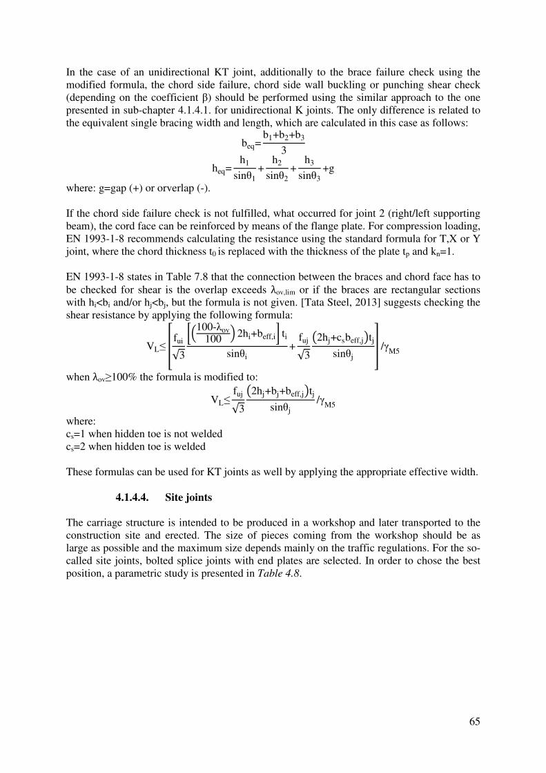
65
In the case of an unidirectional KT joint, additionally to the brace failure check using the modified formula, the chord side failure, chord side wall buckling or punching shear check (depending on the coefficient β) should be performed using the similar approach to the one presented in sub-chapter 4.1.4.1. for unidirectional K joints. The only difference is related to the equivalent single bracing width and length, which are calculated in this case as follows:
beq=b1+b2+b3
3
heq=h1
sinθ1+
h2
sinθ2+
h3
sinθ3+g
where: g=gap (+) or orverlap (-). If the chord side failure check is not fulfilled, what occurred for joint 2 (right/left supporting beam), the cord face can be reinforced by means of the flange plate. For compression loading, EN 1993-1-8 recommends calculating the resistance using the standard formula for T,X or Y joint, where the chord thickness t0 is replaced with the thickness of the plate tp and kn=1. EN 1993-1-8 states in Table 7.8 that the connection between the braces and chord face has to be checked for shear is the overlap exceeds λov,lim or if the braces are rectangular sections with hi<bi and/or hj<bj, but the formula is not given. [Tata Steel, 2013] suggests checking the shear resistance by applying the following formula:
VL≤ 4 fui√3
56100-λov100 7 2hi+beff,i8 ti
sinθi+
fuj√3
�2hj+csbeff,j�tjsinθj
9 /γM5
when λov≥100% the formula is modified to:
VL≤fuj√3
�2hj+bj+beff,j�tjsinθj
/γM5
where: cs=1 when hidden toe is not welded cs=2 when hidden toe is welded These formulas can be used for KT joints as well by applying the appropriate effective width.
4.1.4.4. Site joints
The carriage structure is intended to be produced in a workshop and later transported to the construction site and erected. The size of pieces coming from the workshop should be as large as possible and the maximum size depends mainly on the traffic regulations. For the so-called site joints, bolted splice joints with end plates are selected. In order to chose the best position, a parametric study is presented in Table 4.8.

Table
Option
A
B
C
Table 4.8: Parametric study - site joints positions
Plan view Remarks
Chords: 8 splice joints in total(red); Braces: 8 splice joints in total; 20 but welds to be done in a workshop to connect the chords (green);Max. tensile forces:Right/left side memberChord: NEd=407.75 kNBraces are in compressionRight/left supporting beamChord: NEd=588.52 kNBraces: NEd≈0 kN
Chords: 12 splice joints in total (red); Braces: 12 splice joints in total; 20 but welds to be workshop to connect the chords (green);Max. tensile forces:Right/left side memberChord: NEd=407.75 kNBraces are in compressionConnecting beamChord: NEd=303.88 kNBraces: NEd=365.29 kN
Chords: 12 splice joints in total (red); Braces: 0 splice joints;20 but welds to be done in a workshop to connect the chords (green);Max. tensile forces:Connecting beamChord: NEd=293.36 kN
66
Chords: 8 splice joints in total
Braces: 8 splice joints in
20 but welds to be done in a workshop to connect the
; tensile forces:
Right/left side member =407.75 kN
Braces are in compression Right/left supporting beam
=588.52 kN ≈0 kN
Chords: 12 splice joints in
Braces: 12 splice joints in
20 but welds to be done in a workshop to connect the
; Max. tensile forces: Right/left side member
=407.75 kN Braces are in compression Connecting beam
=303.88 kN =365.29 kN
Chords: 12 splice joints in
splice joints; 20 but welds to be done in a workshop to connect the
; Max. tensile forces: Connecting beam
=293.36 kN

Generally, all three possible options comply with the traffic regulations. Although the forces in the chords for Option B at the positions of splices are lower compared to Option A, and the number of butt welds is the same, in total to be produced and the braces are in compression. chords for Option C are gap K type and the gap length has a quite big value because of the small angle between the brace and chord, the site joint could be placed in the gap. This results in the fact that the site joints are necessary ocause some problems in the construction phase, since certain chords in the connecting beam work as a cantilever before the final stage (see Taking into account all abovethe calculation details can be found in Annex A.
Joints in compression zones should be designed to transmit a certain amount of tAccording to EN 1993-1-8 clause 6.2.7.1(14), splice material should transmit at least 25% of the maximum compressive force in the column, provided that the members are prepared for full contact in bearing. This clause is related to column spFurthermore, [Kurobane et al., 2004] equal to 20% of the column capacity.applied here as well since the lack of the d For the case of the carriage structure under the study and selected option A, and for the brace in the right/left supporting beam, where the axial force is Ntransmit a load equal to 20% of the brace capacity. The brace in the right/left side member is designed to transmit 25% of the compressive force since the brace is in compression. Besides axial tension loading the chords are loaded by bending moments as well. In orderthis, [Packer et al., 2009] suggests designing a joint using a hypothetical effective axial load, as follows:
where: A is the cross-sectional area W is the elastic or plastic section modulus
Generally, all three possible options comply with the traffic regulations. Although the for Option B at the positions of splices are lower compared to Option A,
er of butt welds is the same, Option A is more favorable since it has less joints in total to be produced and the braces are in compression. Since joints between the braces and chords for Option C are gap K type and the gap length has a quite big value because of the small angle between the brace and chord, the site joint could be placed in the gap. This results in the fact that the site joints are necessary only for the chords. On the other hand, this may cause some problems in the construction phase, since certain chords in the connecting beam work as a cantilever before the final stage (see Figure 4.9).
Taking into account all above-mentioned, Option A is selected for the carriage structure and the calculation details can be found in Annex A.
Figure 4.9: Site joints - Option C
Joints in compression zones should be designed to transmit a certain amount of t8 clause 6.2.7.1(14), splice material should transmit at least 25% of
the maximum compressive force in the column, provided that the members are prepared for full contact in bearing. This clause is related to column splices connecting H or I section.
[Kurobane et al., 2004] recommends designing the column for equal to 20% of the column capacity. Although this approach is dedicated to columns, it is applied here as well since the lack of the design recommendations for hollow section trusses.
For the case of the carriage structure under the study and selected option A, and for the brace in the right/left supporting beam, where the axial force is NEd≈0 kN, the splice is designed to
oad equal to 20% of the brace capacity. The brace in the right/left side member is designed to transmit 25% of the compressive force since the brace is in compression. Besides axial tension loading the chords are loaded by bending moments as well. In order
suggests designing a joint using a hypothetical effective axial load,
NEd,eff= �NEd
A+
MEd
W A
W is the elastic or plastic section modulus
67
Generally, all three possible options comply with the traffic regulations. Although the tensile for Option B at the positions of splices are lower compared to Option A,
Option A is more favorable since it has less joints ween the braces and
chords for Option C are gap K type and the gap length has a quite big value because of the small angle between the brace and chord, the site joint could be placed in the gap. This results
nly for the chords. On the other hand, this may cause some problems in the construction phase, since certain chords in the connecting beam
selected for the carriage structure and
Joints in compression zones should be designed to transmit a certain amount of tensile forces. 8 clause 6.2.7.1(14), splice material should transmit at least 25% of
the maximum compressive force in the column, provided that the members are prepared for lices connecting H or I section.
recommends designing the column for a tensile load Although this approach is dedicated to columns, it is
esign recommendations for hollow section trusses.
For the case of the carriage structure under the study and selected option A, and for the brace 0 kN, the splice is designed to
oad equal to 20% of the brace capacity. The brace in the right/left side member is designed to transmit 25% of the compressive force since the brace is in compression. Besides axial tension loading the chords are loaded by bending moments as well. In order to account
suggests designing a joint using a hypothetical effective axial load,
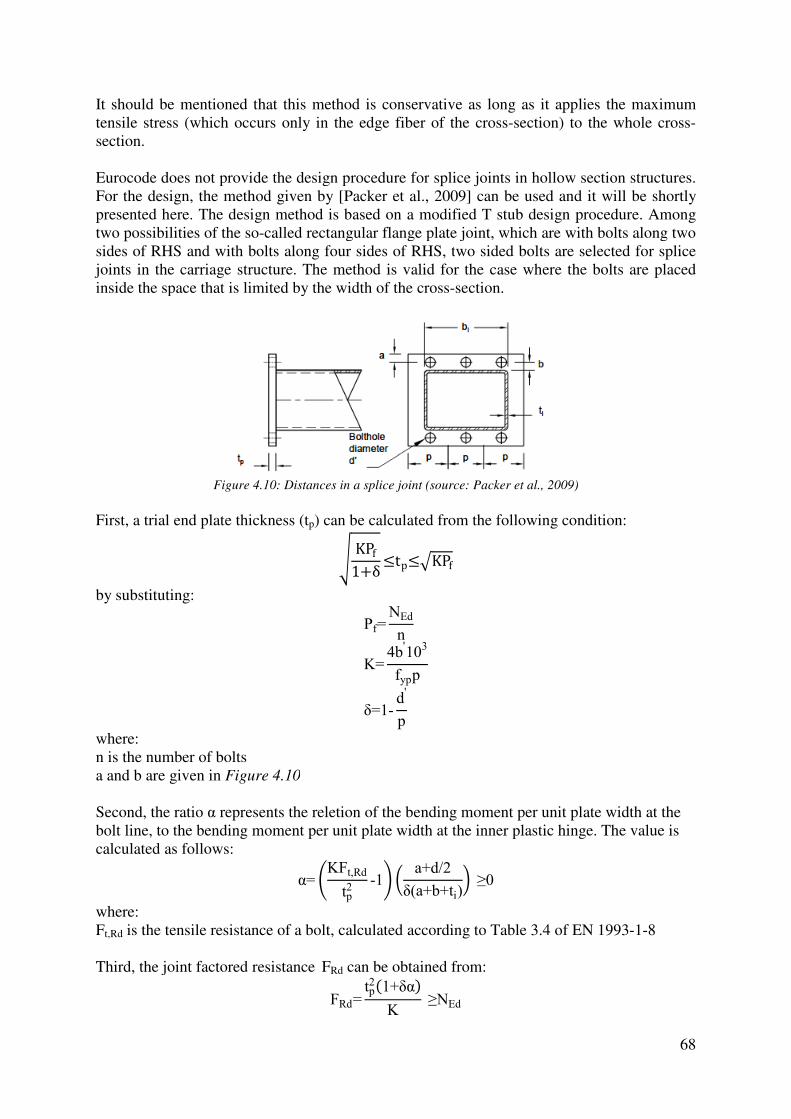
It should be mentioned that this tensile stress (which occurs only in the edge fiber of the crosssection. Eurocode does not provide the design procedure forFor the design, the method given bypresented here. The design method is based on a modified T stub design procedure. Among two possibilities of the so-called rectangular flange plate joint, which aresides of RHS and with bolts along four sides of RHS, tjoints in the carriage structure. The method is valid for the case where the bolts are placed inside the space that is limited by the width o
Figure 4.10: Distances
First, a trial end plate thickness (t
by substituting:
where: n is the number of bolts a and b are given in Figure 4.10
Second, the ratio α represents the reletion of the bending moment per unit plate width at the bolt line, to the bending moment per unit plate widthcalculated as follows:
where: Ft,Rd is the tensile resistance of a bolt, calculated according to Table 3.4 of EN 1993 Third, the joint factored resistance
It should be mentioned that this method is conservative as long as it applies the maximum tensile stress (which occurs only in the edge fiber of the cross-section) to the whole cross
Eurocode does not provide the design procedure for splice joints in hollow section structures. given by [Packer et al., 2009] can be used and it will be shortly
The design method is based on a modified T stub design procedure. Among called rectangular flange plate joint, which are with bolts along two
sides of RHS and with bolts along four sides of RHS, two sided bolts are selected for splice joints in the carriage structure. The method is valid for the case where the bolts are placed inside the space that is limited by the width of the cross-section.
: Distances in a splice joint (source: Packer et al., 2009
trial end plate thickness (tp) can be calculated from the following condition:
� KPf1+δ =tp=?KPf
Pf=NEd
n
K=4b
'10
3
fypp
δ=1-d
'
p
Figure 4.10
represents the reletion of the bending moment per unit plate width at the bolt line, to the bending moment per unit plate width at the inner plastic hinge. The value is
α= @KFt,Rd
tp2
-1A � a+d/2
δ(a+b+ti) ≥0
is the tensile resistance of a bolt, calculated according to Table 3.4 of EN 1993
Third, the joint factored resistance FRd can be obtained from:
FRd=tp2�1+δα�
K ≥NEd
68
method is conservative as long as it applies the maximum section) to the whole cross-
s in hollow section structures. can be used and it will be shortly
The design method is based on a modified T stub design procedure. Among with bolts along two
wo sided bolts are selected for splice joints in the carriage structure. The method is valid for the case where the bolts are placed
Packer et al., 2009)
) can be calculated from the following condition:
represents the reletion of the bending moment per unit plate width at the at the inner plastic hinge. The value is
is the tensile resistance of a bolt, calculated according to Table 3.4 of EN 1993-1-8

69
In addition, the actual total bolt tension, including prying can be calculated from:
Tf≈Pf B1+b'
a' � δα
1+δα C ≤Nt,Rd
by using the modified ratio α from the equation:
α= @KPf
tp2 -1A 1
δ ≥0
where: a'=a+d/2 b'=b-d/2+ti a≤1.25b
4.1.5. Material specification
After the detailed design stage the weight of the structure can be estimated precisely, considering a real length of each structural member and multiplying it by its unit weight (per m1). The summary is given in Table 4.9 for each cross-sectional size used in the structure, as well as for additional plates used in the structure in Table 4.10. Detailed tables, with the exact length of each member and its weight can be found in Annex A.
Table 4.9: Solution 6-1, summary of the weight (structural members)
Section Total length [m]
Weight [kg/m1]
Total weight [kg]
SHS 350x350x12.5 122.33 127 15536.16 RHS 200x100x6 49.26 26.4 1300.47 RHS 200x100x8 19.45 33.9 659.22 RHS 160x80x5 14.18 17.5 248.15 SHS 150x150x6 18.40 26.4 485.76
SHS 200x200x10 12.41 57 707.48 HEB 360 30.74 142 4365.65 HEA 800 13.20 224 2956.80 IPE 550 5.07 105 537.42
Σ 26797.11
Table 4.10: Solution 6-1, summary of the weight (additional items)
Item Dimensions [mm]
Weight [kg]
Quantity Total weight [kg]
End plate (chord) 520x400x22 35.92 16 574.75 End plate (brace SB12)
220x210x12 4.35 8 34.82
End plate (brace SM11)
310x220x12 6.42 8 51.40
Chord face stiffener 500x350x15 20.06 2 41.21 Σ 702.17
This Thesis does not analyze in detail joints between the brackets and trusses, sub-assemblies intended to fix roller bogies to the structure, sub-assemblies for fixing the platform columns and caissons, etc. In order to compensate this and estimate the final weight of the structure, all these parts will be accounted as 10% of the structural weight (see Table 4.11).

70
Table 4.11: Solution 6-1, summary of the weight (total)
Item Weight [kg]
Structural members 26797.11 Plates 702.17 +10% of the structural weight 2679.71 Total 30178.99
As an overview of the contribution of parts of the structure to the total weight Table 4.12 is given. The braces contribute only with 11.93% to the total weight, but on contrary they require more labor for the production than other parts of the structure.
Table 4.12: Solution 6-1, contribution of parts of the structure to the total weight
Part of the structure Weight [kg]
Contribution [%]
Chords 15536.16 57.98 Braces 3197.64 11.93 Brackets 8063.31 30.09 Total 26797.11 100.00
4.2. Bolted solution made of hollow section chords and angles as braces (Solution 6-2)
4.2.1. Improvements and final layout of the structure
This chapter will present the final layout of Solution 6-2 and the methodology used during the design will be given in the following sub-chapters. The computation details can be found in Annex B. Generally, Solution 6-2 is a variant of Solution 6-1, developed upon a suggestion of the DREVER International representatives. This solution has been conceived with the aim to analyze the feasibility of the carriage structure in the case where the fabrication facilities are limited. This means that a part of the fabrication process is moved from the workshop to the site. In addition, the structure can be transported easily because all structural parts can fit in one shipping container and later connected on a site. The layout, shown in Figure 4.11 with its cross-sections, is almost the same as the layout of Solution 6-1. In terms of the geometry, both solutions are completely the same. The only difference is related to the brace members, which are in Solution 6-2 composed of hot rolled L profiles (single and double configuration), connected to the chords by means of bolted connections. To obtain a bolted connection between the brace and the chord, a gusset plate welded to the chord should be used. The thickness of all gusset plates in the structure is 12 mm. The chords remain unchanged compared to Solution 6-1. Only three sizes of L profiles are used for the whole structure to simplify the procurement and on the other hand the variation among single and double configuration is performed (depending on the necessary stiffness) with the aim to save the material (see Figure 4.12) The double configuration is mainly in the form of back-to-back oriented angles. A star-battened configuration is applied for the vertical braces at the intersection of the mutually perpendicular trusses, where the gusset plate on the bottom chord has perpendicular direction to the gusset plate on the upper chord (see Figure 4.13).

Figure 4.11
Figure
Figure 4.13: Solution
In order to reach a higher level of the uniformity in the fabrication, all bolt holes on the braces are placed at the same positions, keeping the values of the end distancespacing p1=70 mm (see Figure 4.14the compliance with Table 3.3 of EN 1993spacing, end and edge distances. An exception is the brace member SB16 (next to the vertical support) where the distances are higher and M20 bolts are used. grade 8.8.
11: Solution 6-2, improved structural layout - 3D view
Figure 4.12: Solution 6-2, angle configurations
: Solution 6-2, braces and gusset plates at the intersections
In order to reach a higher level of the uniformity in the fabrication, all bolt holes on the braces are placed at the same positions, keeping the values of the end distance
Figure 4.14). For the bolts used (M12 and M16) the Table 3.3 of EN 1993-1-8 where are defined minimum and maximum
g, end and edge distances. An exception is the brace member SB16 (next to the vertical ) where the distances are higher and M20 bolts are used. All bolts in the structure are
71
2, braces and gusset plates at the intersections
In order to reach a higher level of the uniformity in the fabrication, all bolt holes on the braces are placed at the same positions, keeping the values of the end distance e1=50 mm and
For the bolts used (M12 and M16) the distances are in 8 where are defined minimum and maximum
g, end and edge distances. An exception is the brace member SB16 (next to the vertical All bolts in the structure are

Figure 4.14
4.2.2. Serviceability limit states
The serviceability limit state checks are presented here as long as they are governing for the design of the carriage structurepresented in Table 4.13 and an illustration of the deformed shape for loadgiven in Figure 4.15.
Table 4
Figure 4.15: Solution 6
4.2.3. Ultimate limit states
4.2.3.1. Design of cross
Generally, the majority of the methodology used in the design of Solution 6Solution 6-2 as well. In this substatements given in sub-chapter 4.1.3.1 and they are related to the brace members. According to clause 3.10.3(2) of EN 1993row of bolts in one leg may be treated as concentrically loaded ov
14: End distance and spacing of bolts for an angle
Serviceability limit states
The serviceability limit state checks are presented here as long as they are governing for the of the carriage structure. The maximum values of the vertical displacements are
and an illustration of the deformed shape for load
4.13: Solution 6-2, vertical displacements [mm]
z(X1) 1.28
≤6.85 z(X2) 6.79 z(X3) 6.81 z(X4) 6.78
: Solution 6-2, deformed model for load combination X3
Ultimate limit states
Design of cross-sections
Generally, the majority of the methodology used in the design of Solution 6In this sub-chapter will be presented only the facts that differ from the
chapter 4.1.3.1 and they are related to the brace members.
According to clause 3.10.3(2) of EN 1993-1-8, a single angle in tension connected by a single n one leg may be treated as concentrically loaded over an effective net section.
72
The serviceability limit state checks are presented here as long as they are governing for the . The maximum values of the vertical displacements are
and an illustration of the deformed shape for load combination X3 is
2, deformed model for load combination X3
Generally, the majority of the methodology used in the design of Solution 6-1 applies for that differ from the
chapter 4.1.3.1 and they are related to the brace members.
8, a single angle in tension connected by a single r an effective net section.

73
The design formulas are given in Table 4.14. In the carriage structure, all braces are connected by either two or three bolts in a single row to the gusset plate.
Table 4.14: Design of cross-sections (angle in tension) - formulas summary
Situation Design resistance Design check
Axial tension
Npl,Rd=A·fy
γM0
EN 1993-1-1 (6.6)
Nu,Rd=β2A
net·fu
γM2
EN 1993-1-8 (3.12)
Nu,Rd=β3A
net·fu
γM2
EN 1993-1-8 (3.13)
NEd
Nt,Rd≤1
EN 1993-1-1 (6.5) where:
Nt,Rd=min (Npl,Rd, Nu,Rd)
The reduction factors β2 (2 bolts) and β3 (3 bolts) are dependent on the pitch p1 and the bolt hole diameter d0. Their values can be found in Table 3.8 of EN 1993-1-8 and they vary between 0.4 and 0.7. The partial safety factors are γM0=1.00 and γM2=1.25 as it is recommended by Eurocode. Details of the calculations are given in Annex B.
4.2.3.2. Stability of structural members
The design methodology for stability checks of chords, described in 4.1.3.2. applies here as well. Angles as web members are the specific case, since they are connected to the gusset plate by bolts in one leg. According to Annex BB1 of EN 1993-1-1, if an angle is fixed appropriately (at least two bolts if bolted) the eccentricities may be neglected and end fixities allowed for in the design of angles as web members in compression. The effective relative slenderness should be calculated in this case as:
λ�eff,v=0.35+0.7λ�v λ�eff,y=0.50+0.7λ�y λ�eff,z=0.50+0.7λ�z
The buckling length should be taken as equal to the system length for angles designed using the effective relative slenderness. Resulting from the fact that the design of the carriage structure is governed by the serviceability limit states, the braces composed of back-to-back oriented angles satisfy the stability checks without a need to interconnect them, what simplifies the fabrication. This means that the buckling resistance is calculated for one single angle and multiplied by 2 in order to obtain the final resistance which has to be compared with the acting force NEd. The vertical braces at the intersection of mutually perpendicular trusses are composed as a star-battened configuration. According to clause 6.6.4 of EN 1993-1-1, they can be designed as a single integral member provided that the maximum distance between the battens is 70imin, where imin is the minimum radius of gyration of one angle. For L 90x90x10 mm, that is used in this case, 70 imin=1225 mm, what means that the battens will be placed at the ends of the brace. The connection between the angle and batten is bolted to keep the consistency

74
with all other connections. The shear force that has to be transferred by the battens is negligible compared to the resistance of a bolt M12 and the values can be found in Annex B.
4.2.4. Design of joints
4.2.4.1. Brace members connected by bolts
Generally, the connection between the brace member and gusset plate is bearing type (type A) according to Table 3.2 of EN 1993-1-8, thus the design ultimate shear resistance and the design bearing resistance should be checked, as well as the design block tearing resistance for members loaded in tension. Besides the axial forces, the bolts are loaded by bending moments due to the fact that the bolt row does not coincide with the axis of the angle. The analogy could be made to the resistance of the bolt group for a fin plate connection, given in [Jaspart and Weynand, 2016]. The bolt group resistance to shear forces should be calculated as follows:
Vv,Rd=nFv,Rd
�1+ @ 6e�n+1�p1A2
where: Fv,Rd is the resistance of a single bolt per shear plane (EN 1993-1-8, Table 3.4) n is the number of bolts e is the eccentricity between the bolt row and the axis of the angle p1 is the spacing between bolts For the bolts used in the carriage structure (grade 8.8), the design shear resistance Fv,Rd is given in Table 4.15.
Table 4.15: Bolt shear resistance per shear plane
Bolt size Fv,Rd [kN] M12 43.43 M16 77.21 M20 120.60
Using the same analogy, the design bearing resistance of the bolt group should be calculated as:
Vb,Rd=n
�� 1Fb,lg,Rd
2
+ � β0Fb,tr,Rd
2
where:
β0=6e�n+1�p1
Fb,lg,Rd and Fb,tr,Rd are the design bearing resistances of a plate per bolt, in the longitudinal and transversal direction, respectively (EN 1993-1-8, Table 3.4) In addition, for members in tension, according to clause 3.10.2 of EN 1993-1-8 the block tearing resistance should be checked as well, and for a bolt group subject to eccentric loading the following formula applies:

where: Ant is net area subjected to tensionAnv is net area subjected to shear(see Figure 4.16)
Figure 4.16: Areas subjected to tension and shear for the block tearing resistance check
4.2.4.2. Gusset plates
Generally, a gusset plate provides a simple way to connect the axially loaded brace members to the chord by the means of bolts in shear. bearing resistance of the gusset plate, and the block tearing resistanthe methodology explained in the previous subgusset plate connects the braces oriented in different directions to the chord, a complex stress state occurs in the gusset plate. In order tgusset plate, as well as its stability, According to many authors [Jaspart and Weynand, 2016], [Thornton et al. 2011] etc.,peak stress occurs on the Whitmore section (Whitmore, 1952). The Whitmore section is placed at the last row of fasteners, and the sothe distance between two lines starting at the first bolt row and radiating outward at 30°Figure 4.17).
Veff,Rd=0.5fu
Ant
γM2
+1√3
fyAnv
γM0
is net area subjected to tension ted to shear
: Areas subjected to tension and shear for the block tearing resistance check
Gusset plates
Generally, a gusset plate provides a simple way to connect the axially loaded brace members to the chord by the means of bolts in shear. Local failure checks should be conducted for the bearing resistance of the gusset plate, and the block tearing resistance where is relevant using the methodology explained in the previous sub-chapter. Resulting from the fact that the gusset plate connects the braces oriented in different directions to the chord, a complex stress state occurs in the gusset plate. In order to check the tension/compression resistance of a gusset plate, as well as its stability, the peak tensile/compressive stress should be calculated.
[Jaspart and Weynand, 2016], [Thornton et al. 2011] etc.,the Whitmore section (Whitmore, 1952). The Whitmore section is
placed at the last row of fasteners, and the so-called Whitmore effective widththe distance between two lines starting at the first bolt row and radiating outward at 30°
leff=2�n-1�p1
tan 30°
Figure 4.17: Whitmore section
75
: Areas subjected to tension and shear for the block tearing resistance check
Generally, a gusset plate provides a simple way to connect the axially loaded brace members Local failure checks should be conducted for the
ce where is relevant using Resulting from the fact that the
gusset plate connects the braces oriented in different directions to the chord, a complex stress o check the tension/compression resistance of a
the peak tensile/compressive stress should be calculated. [Jaspart and Weynand, 2016], [Thornton et al. 2011] etc., the
the Whitmore section (Whitmore, 1952). The Whitmore section is width (leff) is equal to
the distance between two lines starting at the first bolt row and radiating outward at 30° (see

On the Whitmore effective width, for supported members in tension the following should be checked:
- Design plastic resistance- Net section resistance
while members in compression should be checked for:- Design plastic resistance- Stability (flexural buckling)
Regarding the flexural buckling of a gusset plate checking a gusset plate as a columnbuckling length equal to:
The distances l1 to l3 are presented graphically in coefficient K should be taken equal to 0.65.
Figure
Besides the local checks, according to checked for the global cross section failure under the resultant of forces transferred by mthan one of the supported members. The critical section is given in be checked for normal and shear stress according to the theory of elasticity. The members are designed with the centre lines noding, what means that the critiaxial forces, shear forces and bending moments.
Figure
On the Whitmore effective width, for supported members in tension the following should be
Design plastic resistance
while members in compression should be checked for: Design plastic resistance Stability (flexural buckling)
Regarding the flexural buckling of a gusset plate [Jaspart and Weynand, 2016] checking a gusset plate as a column following the rules given in EN 1993
Lcr=Kl1+l2+l3
3
are presented graphically in Figure 4.18 and the buckling length coefficient K should be taken equal to 0.65.
Figure 4.18: Whitmore section and buckling lengths
Besides the local checks, according to [Jaspart and Weynand, 2016] a gusset plate should be checked for the global cross section failure under the resultant of forces transferred by mthan one of the supported members. The critical section is given in Figure 4.19
be checked for normal and shear stress according to the theory of elasticity. The members are designed with the centre lines noding, what means that the critical section is subjected to axial forces, shear forces and bending moments.
Figure 4.19: Gusset plate - critical cross-section
76
On the Whitmore effective width, for supported members in tension the following should be
[Jaspart and Weynand, 2016] suggests following the rules given in EN 1993-1-1, with the
he buckling length
a gusset plate should be checked for the global cross section failure under the resultant of forces transferred by more
Figure 4.19 and it should be checked for normal and shear stress according to the theory of elasticity. The members are
cal section is subjected to

77
Forces acting on the critical section are: - Axial force NEd=NEd,1sinθ1-NEd,2sinθ2 - Shear force VEd=NEd,1cosθ1+NEd,2cosθ2 - Bending moment MEd= NEd,1d1sinθ1+ NEd,2d2sinθ2
The design check is in terms of the elastic stresses, as follows: NEd
A±
MEd
W≤fy
1.5VEd
A≤
fy√3
In the calculations the critical section is assumed to be adjacent to the chord, neglecting the fillet weld thickness. The gusset plate is welded to the chord by the means of double sided fillet welds. In order to allow the predicted failure mode to occur before the weld failure, the full strength double fillet welds are applied, what is stated in Chapter 7 of EN 1993-1-8 and explained in this Thesis in the chapter dedicated for hollow section joints (see 4.1.4.1.). The minimum throat thickness for a full strength double sided fillet weld, for steel grade S235 should be a≥0.46t as it is stated in [Jaspart and Weynand, 2016]. As long as the thickness of the gusset plate is 12 mm, the throat thickness of the weld should be 6 mm, what is an advantage from the fabrication point of view because welds up to 6 mm can be produced in one pass. A guidance is given in Table 7.13 of EN 1993-1-8 for the so-called longitudinal plate. The relevant failure mode is the chord face failure, what results from low β ratios (the gusset plate thickness to the chord width). Due to the fact that the gusset plate transfers axial forces, shear forces and bending moments to the chord face (see forces acting on the critical section in 4.2.4.3. and Figure 4.19) an additional guidance is necessary, because EN 1993-1-8 provides a formula only for the axially loaded longitudinal plate. To avoid the punching shear failure, a criterion is given in [Kurobane et al., 2004] for simple shear joints to hollow section columns and according to [Packer et al., 2009] it is applicable for longitudinal gusset plates as well. The criterion is to ensure that the tension resistance of the tab under axial load is less than the shear resistance of the RHS wall along two planes. To satisfy this criterion, the following formula applies:
tp<1.16fy0
fypt0
where: tp is the thickness of the gusset plate t0 is the thickness of the chord fy0 is the yield strength of the chord fyp is the yield strength of the gusset plate For the carriage structure, where the same steel grade is used for all parts of the structure, and t0=12.5 mm, the criterion becomes:
tp<1.16·235
235·12.5
tp<14.5 mm As it was mentioned previously, the selected thickness of the gusset plate is tp=12 mm what is in compliance with the criterion above.
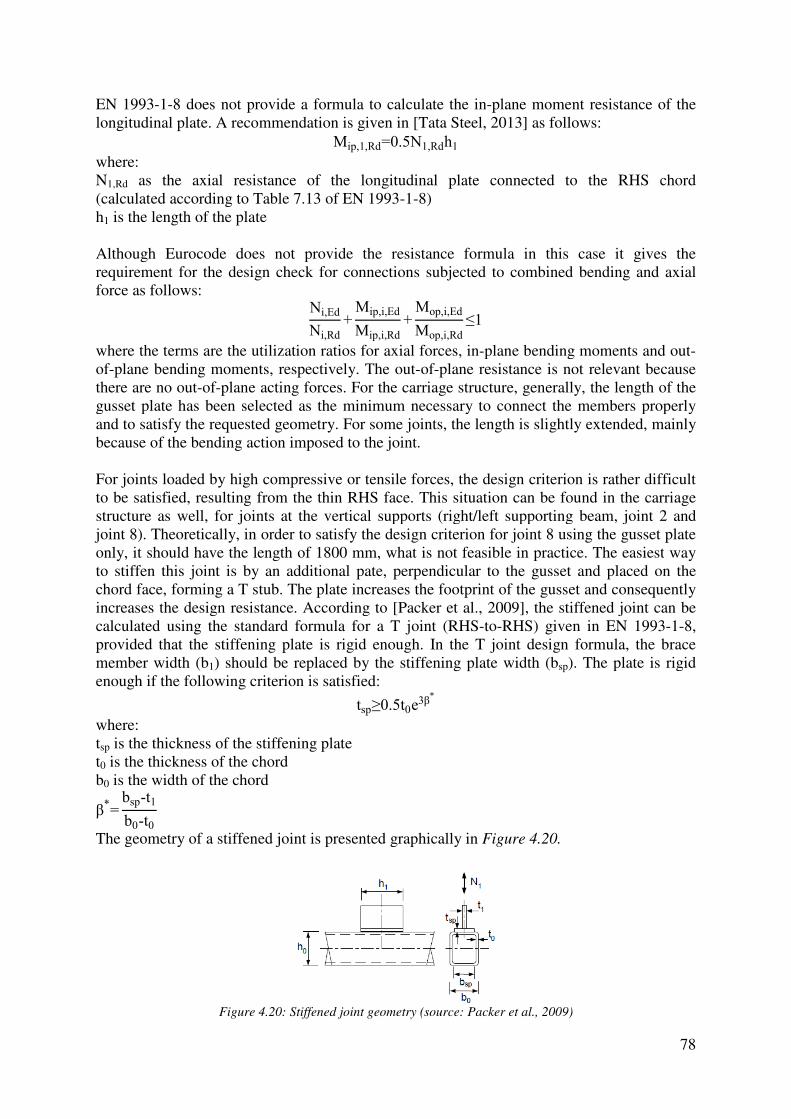
EN 1993-1-8 does not provide a formula to calculate the inlongitudinal plate. A recommendation is given in
where: N1,Rd as the axial resistance of the longitudinal plate connected to the RHS chord (calculated according to Table 7.13 of EN h1 is the length of the plate Although Eurocode does not provide the resistance formula in this case it gives the requirement for the design check for connections subjected to combined bending and axial force as follows:
where the terms are the utilization ratios for axial forces, inof-plane bending moments, respectively. The outthere are no out-of-plane acting forces.gusset plate has been selected as the minimum necessary to connect the members properly and to satisfy the requested geometry. For some joints, the length is slightly extended, mainly because of the bending action imposed to the joint. For joints loaded by high compressive or tensile forces, the design criterion is rather difficult to be satisfied, resulting from the thin RHS face. structure as well, for joints at the vertical supports (right/left supporting beam, joint 2 and joint 8). Theoretically, in order to satisfy the design criterion for joint 8 using the gusset plate only, it should have the length of 1800 mm, what is not feasible in practice. The easiestto stiffen this joint is by an additional pate, perpendicular to the gusset and placed on the chord face, forming a T stub. increases the design resistance. According to calculated using the standard formula for a T joint (RHSprovided that the stiffening plate is rigid enough. In the T joint design formula, the brace member width (b1) should be replaced by thenough if the following criterion is satisfied:
where: tsp is the thickness of the stiffening platet0 is the thickness of the chordb0 is the width of the chord
β*=
bsp-t1
b0-t0
The geometry of a stiffened joint is presented graphically in
Figure 4.20: Stiffened joint geometry (source:
8 does not provide a formula to calculate the in-plane moment A recommendation is given in [Tata Steel, 2013] as follows:
Mip,1,Rd=0.5N1,Rdh1
as the axial resistance of the longitudinal plate connected to the RHS chord (calculated according to Table 7.13 of EN 1993-1-8)
Although Eurocode does not provide the resistance formula in this case it gives the requirement for the design check for connections subjected to combined bending and axial
Ni,Ed
Ni,Rd
+Mip,i,Ed
Mip,i,Rd
+Mop,i,Ed
Mop,i,Rd
≤1
where the terms are the utilization ratios for axial forces, in-plane bending moments and outplane bending moments, respectively. The out-of-plane resistance is not relevant because
plane acting forces. For the carriage structure, generally, the length of the gusset plate has been selected as the minimum necessary to connect the members properly and to satisfy the requested geometry. For some joints, the length is slightly extended, mainly
g action imposed to the joint.
For joints loaded by high compressive or tensile forces, the design criterion is rather difficult to be satisfied, resulting from the thin RHS face. This situation can be found in the carriage
at the vertical supports (right/left supporting beam, joint 2 and Theoretically, in order to satisfy the design criterion for joint 8 using the gusset plate
only, it should have the length of 1800 mm, what is not feasible in practice. The easiestan additional pate, perpendicular to the gusset and placed on the
chord face, forming a T stub. The plate increases the footprint of the gusset increases the design resistance. According to [Packer et al., 2009], the stiffened joint can be calculated using the standard formula for a T joint (RHS-to-RHS) given in EN 1993provided that the stiffening plate is rigid enough. In the T joint design formula, the brace
) should be replaced by the stiffening plate width (bsp). The plate is rigid enough if the following criterion is satisfied:
tsp≥0.5t0e3β*
is the thickness of the stiffening plate is the thickness of the chord
f a stiffened joint is presented graphically in Figure 4.20.
: Stiffened joint geometry (source: Packer et al., 2009)
78
plane moment resistance of the as follows:
as the axial resistance of the longitudinal plate connected to the RHS chord
Although Eurocode does not provide the resistance formula in this case it gives the requirement for the design check for connections subjected to combined bending and axial
plane bending moments and out-plane resistance is not relevant because
e carriage structure, generally, the length of the gusset plate has been selected as the minimum necessary to connect the members properly and to satisfy the requested geometry. For some joints, the length is slightly extended, mainly
For joints loaded by high compressive or tensile forces, the design criterion is rather difficult This situation can be found in the carriage
at the vertical supports (right/left supporting beam, joint 2 and Theoretically, in order to satisfy the design criterion for joint 8 using the gusset plate
only, it should have the length of 1800 mm, what is not feasible in practice. The easiest way an additional pate, perpendicular to the gusset and placed on the
The plate increases the footprint of the gusset and consequently , the stiffened joint can be
RHS) given in EN 1993-1-8, provided that the stiffening plate is rigid enough. In the T joint design formula, the brace
). The plate is rigid
)

For the carriage structure, the two critical joints are stiffened using is the minimum width that satisfies the design checks. In order to consider this plate rigid enough, the thickness should be tthickness of the stiffening plate has an exponentiformula, what means that the width should be applied as smaller as possible in order to avoid disproportionate thicknesses.
4.2.4.3. Site joints
Solution 6-2 is intended to be the means of bolted connections. As a result, splice jointsthey should be outside the gusset plates in order to avoid complex details. addition to the facts from the case study given in Table 4.16 could be regarded
The splice joint positions are analogous to Option B for Solution 6this case as long as the right/left supporting beam is 12 m long what is equal to the standard mill length of a section. It is worthy to be mentioned that the selection of the splice joint positions in Solution 6-1 was influenced by thewhat is not relevant for Solution 6the workshop as an assembly, as well as the bottom chords. The design methodology for splice joints is already explainedetails for Solution 6-2 are given in Annex B.
For the carriage structure, the two critical joints are stiffened using plates 190 mm wide, what is the minimum width that satisfies the design checks. In order to consider this plate rigid enough, the thickness should be tsp≥30.41 mm. It should be mentioned that the necessary thickness of the stiffening plate has an exponential relation to its width according to the given formula, what means that the width should be applied as smaller as possible in order to avoid
Site joints
2 is intended to be assembled on a site by connecting the braces to the chords by the means of bolted connections. As a result, splice joints are placed at the chords only and they should be outside the gusset plates in order to avoid complex details.
from the case study given in 4.1.4.3. related to Solution 6could be regarded the most reasonable for Solution 6-2.
Table 4.16: Site joints (Solution 6-2)
Chords: 12 splice joints in total (red); 20 but welds to be done in a workshop to connect the chords (green); Max. tensile forces:Right/left side memberChord: NEd=403.55 kNConnecting beam Chord: NEd=303.10
The splice joint positions are analogous to Option B for Solution 6-1 whatthis case as long as the right/left supporting beam is 12 m long what is equal to the standard
. It is worthy to be mentioned that the selection of the splice joint 1 was influenced by the internal forces in brace members as well,
what is not relevant for Solution 6-1. The top chords of the connecting beam will come from the workshop as an assembly, as well as the bottom chords.
The design methodology for splice joints is already explained in 4.1.4.3. and the computation 2 are given in Annex B.
79
plates 190 mm wide, what is the minimum width that satisfies the design checks. In order to consider this plate rigid
It should be mentioned that the necessary al relation to its width according to the given
formula, what means that the width should be applied as smaller as possible in order to avoid
races to the chords by are placed at the chords only and
they should be outside the gusset plates in order to avoid complex details. Considering this in .1.4.3. related to Solution 6-1, the scheme
2.
Chords: 12 splice joints in
20 but welds to be done in a workshop to connect the
Max. tensile forces: Right/left side member
=403.55 kN
303.10 kN
1 what is advantageous in this case as long as the right/left supporting beam is 12 m long what is equal to the standard
. It is worthy to be mentioned that the selection of the splice joint internal forces in brace members as well,
The top chords of the connecting beam will come from
d in 4.1.4.3. and the computation
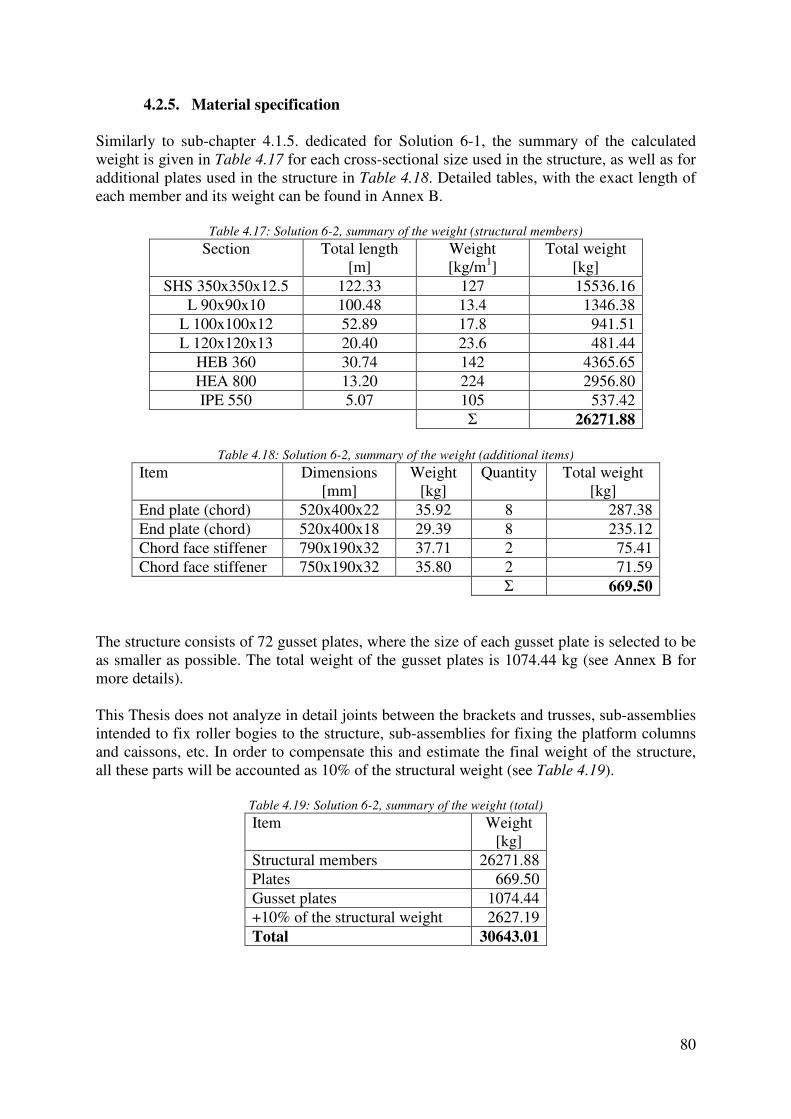
80
4.2.5. Material specification
Similarly to sub-chapter 4.1.5. dedicated for Solution 6-1, the summary of the calculated weight is given in Table 4.17 for each cross-sectional size used in the structure, as well as for additional plates used in the structure in Table 4.18. Detailed tables, with the exact length of each member and its weight can be found in Annex B.
Table 4.17: Solution 6-2, summary of the weight (structural members)
Section Total length [m]
Weight [kg/m1]
Total weight [kg]
SHS 350x350x12.5 122.33 127 15536.16 L 90x90x10 100.48 13.4 1346.38
L 100x100x12 52.89 17.8 941.51 L 120x120x13 20.40 23.6 481.44
HEB 360 30.74 142 4365.65 HEA 800 13.20 224 2956.80 IPE 550 5.07 105 537.42
Σ 26271.88
Table 4.18: Solution 6-2, summary of the weight (additional items)
Item Dimensions [mm]
Weight [kg]
Quantity Total weight [kg]
End plate (chord) 520x400x22 35.92 8 287.38 End plate (chord) 520x400x18 29.39 8 235.12 Chord face stiffener 790x190x32 37.71 2 75.41 Chord face stiffener 750x190x32 35.80 2 71.59
Σ 669.50
The structure consists of 72 gusset plates, where the size of each gusset plate is selected to be as smaller as possible. The total weight of the gusset plates is 1074.44 kg (see Annex B for more details). This Thesis does not analyze in detail joints between the brackets and trusses, sub-assemblies intended to fix roller bogies to the structure, sub-assemblies for fixing the platform columns and caissons, etc. In order to compensate this and estimate the final weight of the structure, all these parts will be accounted as 10% of the structural weight (see Table 4.19).
Table 4.19: Solution 6-2, summary of the weight (total)
Item Weight [kg]
Structural members 26271.88 Plates 669.50 Gusset plates 1074.44 +10% of the structural weight 2627.19 Total 30643.01

81
Table 4.20 is an overview of the contribution of each part of the structure to the final weight. Similarly to Solution 6-1, for Solution 6-2 the braces participate only with 10.17% to the final weight.
Table 4.20: Solution 6-2, contribution of parts of the structure to the total weight
Part of the structure Weight [kg]
Contribution [%]
Chords 15536.16 59.14 Braces 2672.41 10.17 Brackets 8063.31 30.69 Total 26271.88 100.00
4.3. Final comparison between the solutions
Although some of the benefits or drawbacks have already been mentioned in the text, the main aim of this sub-chapter is to summarize the results from the detailed design stage for Solution 6-1 and Solution 6-2 and to compare them with the initial one. All these solutions were designed in such a way to satisfy the serviceability limit state criterion, as well as the ultimate limit state design checks, what is comprehensively explained in the previous chapters. To compare the estimated weight between the solutions Table 4.21 is given.
Table 4.21: Estimated final weight - comparison
Solution Weight [kg]
∆G [kg]
Initial solution 36268.14 / Solution 6-1 30178.99 -6089.15 Solution 6-2 30643.01 -5625.13
Both solutions, developed from Solution 6 proposed in the pre-design stage, have similar weight, what is expected due to the fact that the brace members are the only difference among them. Comparing them to the initial solution, the material saving is significant and given in numbers, approximately 6.1 t of steel for Solution 6-1 and 5.6 t for Solution 6-2. It is worthy to be mentioned that the rough estimation given in the pre-design stage underestimated the material savings, mainly because model for the calibration underestimated the dead weight (comparison between the proposed solutions was based on the vertical reactions). For instance, Solution 6 was selected mainly because of the fabrication (with the aim to replace built-up box sections with commercial hollow sections) what resulted at the end in a considerably lighter structure. Generally, there are two reasons in this case that allowed the weight reduction. The height of the trusses is 1500+350=1850 mm while the height of the box girders in the initial solution is 1165 mm, what means that Solutions 6-1 and 6-2 have higher stiffness-to-weight ratio compared to the initial solution. Basically, this height was selected in order to compose the truss with a proper geometry (approved by the DREVER International representatives as well). The second reason is related to the type of beams, since a truss girder provides more possibilities for the optimization than a built-up box. For instance, a built-up box girder is made of plates, and its cross-sectional dimensions are often constant along the axis, or changed in a certain node. On contrary, each member of a truss can be adopted with different cross-sectional size between the nodes.

82
Generally, a comparison between Solution 6-1 and Solution 6-2 is mainly related to the fabrication process, as long as the weight of the structure is similar for both solutions (Solution 6-2 is 464.02 kg heavier, what is negligible compared to the total weight of the structure). If a workshop is well equipped, Solution 6-1 may be advantageous. The structure can be produced almost completely in the workshop, transported to the site on a standard truck's trailer and assembled by the means of bolted connections (site joints). If the fabrication facilities of a workshop are limited, Solution 6-2 may be applied, where a part of the fabrication process is moved from the workshop to the site. In the workshop, the following is done: cutting of the sections, drilling of the holes and welding the gusset plates to the chords. On the site the braces are connected to the chords by the means of bolted connections. In addition, the structure can be transported easily because all structural parts can fit in one shipping container and later connected on a site. Regarding the corrosive protection, Solution 6-1 is advantageous, because hollow sections have smaller surface exposed to the environment compared to open sections.
5. Conclusions
The main aim of this thesis was to optimize the transfer carriage structure through the improvements of the structural system, where the design is guided by the serviceability limit states criteria. On the basis of the results and their interpretation given in the previous chapters, the following conclusions can be drawn:
- Solution 6 (composed of planar trusses made of hollow sections) was selected at the pre-design stage among eight proposed solutions as the best compromise between the fabrication complexity and material savings.
- Solution 6 was improved during the detailed design and studied in two variants, namely: Solution 6-1 (Welded solution made completely of hollow sections) and Solution 6-2 (Bolted solution made of hollow section chords and angles as braces).
- The final reduction of the weight compared to the initial solution is: 6089.15 kg for Solution 6-1 and 5625.13 kg for Solution 6-2, what means that a truss girder provides more possibilities for the material savings than a built-up box.
- Design of cross-sections and stability of structural members are not governing for the design what is obvious from the design checks, where the utilization ratio is mainly below 0.5.
- Design of joints had important influence on the design, in terms of the layout and dimensions, in order to satisfy the validity limits given in EN 1993-1-8.
- The selected solutions impose smaller loads to the crane runway beams compared to the initial solution. Optimization of the runway structure could be a subject of future studies.

83
References
CEN, EN 13001-1: Cranes - General design - Part 1: General principles and requirements, European Committee for Standardization, 2015 CEN, EN 13001-2: Cranes - General design - Part 2: Load actions, European Committee for Standardization, 2014
CEN, EN 13001-3-1: Cranes - General design - Part 3: Limit states and proof of competence of steel structures, European Committee for Standardization, 2012 CEN, EN 1993-1-1: Eurocode 3: Design of steel structures. Part 1-1: General rules and rules for buildings, European Committee for Standardization, 2005 CEN, EN 1993-1-8: Eurocode 3: Design of steel structures. Part 1-8: Design of joints, European Committee for Standardization, 2005 DREVER International "Note de calcul pour justification du chariot pre-cooler, des poutres de roulement et des colonnes", 2014 FEM 1.001: Rules for the design of hoisting appliances, 3rd edition, European Materials Handling Federation, 1998 J. Wardenier, J.A. Packer, X.-L. Zhao, van der Vegte "Hollow sections in structural applications", ISBN 978-90-72830-86-9, 2010 J.A. Packer, J. Wardenier, X.-L. Zhao, G.J. van der Vegte, Y. Kurobane "Design guide for rectangular hollow section (RHS) joints under predominantly static loading", ISBN 978-3-938817-04-9, 2009 J.-P. Jaspart, K. Weynand "Design of joints in steel and composite structures", ISBN 978-3-433-02985-5, 2016 Tata Steel Europe Limited "Design of welded joints", 2013 Thornton W., Lini C. "The Whitmore Section", Modern steel construction, 2011 Y. Kurobane, J.A. Packer, J. Wardenier, N. Yeomans "Design guide for structural hollow section column connections", ISBN 3-8249-0802-6, 2004

84
A. Annex A List of tables
Table A.1: Material properties and partial safety factors .............................................................................. 86 Table A.2: Designation - brace members ...................................................................................................... 86 Table A.3: Tension forces [kN] - right/left side member (braces) ................................................................ 86 Table A.4: Design checks (tension) - right/left side member (braces) .......................................................... 87 Table A.5: Tension forces [kN] - right/left supporting beam (braces) .......................................................... 87 Table A.6: Design checks (tension) - right/left supporting beam (braces) .................................................... 87 Table A.7: Tension forces [kN] - connecting beam (braces) ......................................................................... 87 Table A.8: Design checks (tension) - connecting beam (braces) ................................................................. 88 Table A.9: Cross-section classification for the braces loaded in compression .............................................. 88 Table A.10: Compression forces [kN] - right/left side member (braces) ...................................................... 88 Table A.11: Design checks (compression + stability) - right/left side member (braces) ............................... 88 Table A.12: Compression forces [kN] - right/left supporting beam (braces) ................................................ 89 Table A.13: Design checks (compression + stability) - right/left supporting beam (braces) ........................ 89 Table A.14: Compression forces [kN] - connecting beam (braces) .............................................................. 89 Table A.15: Design checks (compression + stability) - connecting beam (braces) ....................................... 89 Table A.16: Cross-section classification (bottom chords) ............................................................................. 90 Table A.17: Chords - design resistances ....................................................................................................... 90 Table A.18: Internal forces and design checks (bending and
axial forces) - right/left side member (bottom ch.) ................................................................... 90 Table A.19: Internal forces and design checks (shear) - right/left side member (bottom chord) .................. 91 Table A.20: Internal forces and design checks (bending and
axial forces) - right/left suppor. beam (bottom ch.) .................................................................. 91 Table A.21: Internal forces and design checks (shear) - right/left supporting beam (bottom chord) ............ 91 Table A.22: Internal forces and design checks (bending and
axial forces) - connecting beam (bottom chord) ....................................................................... 92 Table A.23: Internal forces and design checks (shear) - connecting beam (bottom chord) ........................... 93 Table A.24: Cross-section classification (upper chords) ............................................................................... 93 Table A.25: Chords - design resistances ....................................................................................................... 93 Table A.26: Internal forces and design checks (bending and
axial forces) - right/left side member (upper ch.) ..................................................................... 93 Table A.27: Internal forces and design checks (shear) - right/left side member (upper chord)..................... 94 Table A.28: Stability checks - right/left side member (upper chord) ............................................................ 94 Table A.29: Internal forces and design checks (bending and
axial forces) - right/left suppor. beam (upper ch.) .................................................................... 94 Table A.30: Internal forces and design checks (shear) - right/left supporting beam (upper chord) .............. 95 Table A.31: Stability checks - right/left supporting beam (upper chord) ...................................................... 95 Table A.32: Internal forces and design checks (bending and
axial forces) - connecting beam (upper chord) ......................................................................... 95 Table A.33: Internal forces and design checks (shear) - connecting beam (upper chord) ............................. 96 Table A.34: Stability checks - connecting beam (upper chord) .................................................................... 96 Table A.35: Cross-section classification (bracket-diagonal) ......................................................................... 96 Table A.36: Compression forces [kN] - bracket (diagonal) .......................................................................... 97 Table A.37: Bracket (diagonal) - design resistances ..................................................................................... 97 Table A.38: Design checks (compression + stability) - bracket (diagonal) ................................................... 97 Table A.39: Cross-section classification (bracket-vertical) ........................................................................... 97 Table A.40: Bracket (vertical) - design resistances ....................................................................................... 97 Table A.41: Internal forces and design checks (bending and axial forces) - bracket (vertical) ..................... 97 Table A.42: Stability checks - bracket (vertical) ........................................................................................... 98 Table A.43: Cross-section classification (bracket-horizontal) ...................................................................... 98 Table A.44: Bracket (horizontal) - design resistances ................................................................................... 98 Table A.45: Internal forces and design checks (bending and axial forces) - bracket (horizontal)................. 98 Table A.46: Stability checks - bracket (horizontal) ....................................................................................... 99 Table A.47: Designation - joints ................................................................................................................... 99 Table A.48: Design checks - Joint 1 (right/left side member) ..................................................................... 100 Table A.49: Design checks - Joint 2 (right/left side member) ..................................................................... 100 Table A.50: Design checks - Joint 3 (right/left side member) ..................................................................... 100

85
Table A.51: Design checks - Joint 4 (right/left side member) ..................................................................... 101 Table A.52: Design checks - Joint 5 (right/left side member) ..................................................................... 101 Table A.53: Design checks - Joint 6 (right/left side member) ..................................................................... 101 Table A.54: Design checks - Joint 7 (right/left side member) ..................................................................... 102 Table A.55: Design checks - Joint 8 (right/left side member) ..................................................................... 102 Table A.56: Design checks - Joint 9 (right/left side member) ..................................................................... 102 Table A.57: Design checks - Joint 10 (right/left side member) ................................................................... 103 Table A.58: Design checks - Joint 11 (right/left side member) ................................................................... 103 Table A.59: Design checks - Joint 12 (right/left side member) ................................................................... 104 Table A.60: Design checks - Joint 13 (right/left side member) ................................................................... 104 Table A.61: Design checks - Joint 1 (right/left supporting beam) ............................................................... 104 Table A.62: Design checks - Joint 2 (right/left supporting beam) ............................................................... 105 Table A.63: Design checks - Joint 3 (right/left supporting beam) ............................................................... 105 Table A.64: Design checks - Joint 4 (right/left supporting beam) ............................................................... 105 Table A.65: Design checks - Joint 5 (right/left supporting beam) ............................................................... 106 Table A.66: Design checks - Joint 6 (right/left supporting beam) ............................................................... 106 Table A.67: Design checks - Joint 7 (right/left supporting beam) ............................................................... 106 Table A.68: Design checks - Joint 8 (right/left supporting beam) ............................................................... 107 Table A.69: Design checks - Joint 9 (right/left supporting beam) ............................................................... 107 Table A.70: Design checks - Joint 10 (right/left supporting beam) ............................................................. 107 Table A.71: Design checks - Joint 11 (right/left supporting beam) ............................................................. 108 Table A.72: Design checks - Joint 12 (right/left supporting beam) ............................................................. 108 Table A.73: Design checks - Joint 13 (right/left supporting beam) ............................................................. 108 Table A.74: Design checks - Joint 14 (right/left supporting beam) ............................................................. 109 Table A.75: Design checks - Joint 15 (right/left supporting beam) ............................................................. 109 Table A.76: Design checks - Joint 16 (right/left supporting beam) ............................................................. 109 Table A.77: Design checks - Joint 1 (connecting beam C1) ....................................................................... 110 Table A.78: Design checks - Joint 2 (connecting beam C1) ....................................................................... 110 Table A.79: Design checks - Joint 3 (connecting beam C1) ....................................................................... 110 Table A.80: Design checks - Joint 4 (connecting beam C1) ....................................................................... 111 Table A.81: Design checks - Joint 5 (connecting beam C1) ....................................................................... 111 Table A.82: Design checks - Joint 6 (connecting beam C1) ....................................................................... 112 Table A.83: Design checks - Joint 7 (connecting beam C1) ....................................................................... 112 Table A.84: Design checks - Joint 1 (connecting beam C2) ....................................................................... 112 Table A.85: Design checks - Joint 2 (connecting beam C2) ....................................................................... 113 Table A.86: Design checks - Joint 3 (connecting beam C2) ....................................................................... 113 Table A.87: Design checks - Joint 4 (connecting beam C2) ....................................................................... 113 Table A.88: Design checks - Joint 5 (connecting beam C2) ....................................................................... 114 Table A.89: Design checks - Joint 6 (connecting beam C2) ....................................................................... 114 Table A.90: Design checks - Joint 7 (connecting beam C2) ....................................................................... 115 Table A.91: Site joints design checks (splices) ........................................................................................... 115 Table A.92: Weight (right/left side member-braces) ................................................................................... 116 Table A.93: Weight (right/left supporting beam-braces) ............................................................................ 116 Table A.94: Weight (connecting beam C1-braces) ..................................................................................... 116 Table A.95: Weight (connecting beam C2-braces) ..................................................................................... 117 Table A.96: Weight (chords) ....................................................................................................................... 117 Table A.97: Weight (brackets) .................................................................................................................... 117
Note: Drawings are provided at the end of the report.
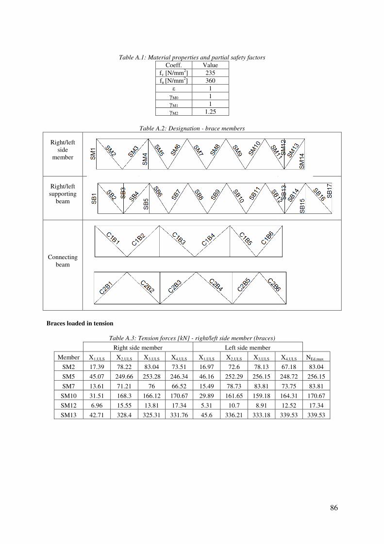
Table A
Right/left side
member
Right/left supporting
beam
Connecting beam
Braces loaded in tension
Table A.3: Tension forces [kN]
Right side member
Member X1,ULS X2,ULS
SM2 17.39 78.22
SM5 45.07 249.66
SM7 13.61 71.21
SM10 31.51 168.3
SM12 6.96 15.55
SM13 42.71 328.4
A.1: Material properties and partial safety factors
Coeff. Value fy [N/mm2] 235 fu [N/mm2] 360
ε 1 γM0 1 γM1 1 γM2 1.25
Table A.2: Designation - brace members
: Tension forces [kN] - right/left side member (braces)
Right side member Left side member
X3,ULS X4,ULS X1,ULS X2,ULS X3,ULS
83.04 73.51 16.97 72.6 78.13
253.28 246.34 46.16 252.29 256.15
76 66.52 15.49 78.73 83.81
166.12 170.67 29.89 161.65 159.18
13.81 17.34 5.31 10.7 8.91
325.31 331.76 45.6 336.21 333.18
86
X4,ULS NEd,max
67.18 83.04
248.72 256.15
73.75 83.81
164.31 170.67
12.52 17.34
339.53 339.53

87
Table A.4: Design checks (tension) - right/left side member (braces)
Member Section A
[mm2] NRd [kN]
NEd/NRd
SM2 RHS 200x100x6 3360 789.6 0.105
SM5 RHS 200x100x8 4320 1015.2 0.252
SM7 RHS 200x100x6 3360 789.6 0.106
SM10 RHS 200x100x6 3360 789.6 0.216
SM12 SHS 150x150x6 3360 789.6 0.022
SM13 SHS 200x200x10 7260 1706.1 0.199
Table A.5: Tension forces [kN] - right/left supporting beam (braces)
Right supporting beam Left supporting beam
Member X1,ULS X2,ULS X3,ULS X4,ULS X1,ULS X2,ULS X3,ULS X4,ULS NEd,max
SB1 25.06 101.75 104.29 99.36 23.3 96.98 99.71 94.39 104.29
SB5 13.96 65.95 63.73 68.26 14.18 70.11 67.6 72.72 72.72
SB6 56.16 192.62 196.42 189.18 57 204.21 208.33 200.45 208.33
SB8 27.04 89.86 92.4 87.5 27.79 97.47 100.15 94.96 100.15
SB10 17.81 78.16 80.5 75.93 18.49 85.47 87.92 83.13 87.92
SB14 63.72 249.02 243.32 255.13 66.11 272.03 265.56 278.92 278.92
SB15 44.38 161.61 159.82 163.69 49.06 182.01 180.09 184.23 184.23
Table A.6: Design checks (tension) - right/left supporting beam (braces)
Member Section A
[mm2] NRd [kN]
NEd/NRd
SB1 RHS 200x100x6 3360 789.6 0.132
SB5 SHS 150x150x6 3360 789.6 0.092
SB6 RHS 200x100x6 3360 789.6 0.264
SB8 RHS 160x80x5 2240 526.4 0.190
SB10 RHS 160x80x5 2240 526.4 0.167
SB14 SHS 200x200x10 7260 1706.1 0.163
SB15 SHS 150x150x6 3360 789.6 0.233
Table A.7: Tension forces [kN] - connecting beam (braces)
Member X1,ULS X2,ULS X3,ULS X4,ULS NEd,max
C1B1 71.16 361.52 358.05 365.44 365.44
C1B3 11.96 40.11 41.41 38.88 41.41
C1B4 22.66 90.72 91.53 90.06 91.53
C1B6 63.88 333.43 329.79 337.47 337.47
C2B2 77.91 322.18 318.17 326.66 326.66
C2B5 91.87 375.19 371.09 379.88 379.88

88
Table A.8: Design checks (tension) - connecting beam (braces)
Member Section A
[mm2] NRd [kN]
NEd/NRd
C1B1 RHS 200x100x8 4320 1015.2 0.360
C1B3 RHS 200x100x6 3360 789.6 0.052
C1B4 RHS 200x100x6 3360 789.6 0.116
C1B6 RHS 200x100x8 4320 1015.2 0.332
C2B2 RHS 200x100x8 4320 1015.2 0.322
C2B5 RHS 200x100x8 4320 1015.2 0.374
Braces loaded in compression
Table A.9: Cross-section classification for the braces loaded in compression
Cross-section c
[mm] t
[mm] c/t Class
RHS 200x100x6 182 6 30.33 1 RHS 200x100x8 176 8 22 1 RHS 160x80x5 145 5 29 1 SHS 150x150x6 132 6 22 1 SHS 200x200x10 170 10 17 1
c≈b-3t Limiting values (S235): Class 1: c/t=33 Class 2: c/t=38 Class 3: c/t=42
Table A.10: Compression forces [kN] - right/left side member (braces)
Right side member Left side member Member X1,ULS X2,ULS X3,ULS X4,ULS X1,ULS X2,ULS X3,ULS X4,ULS NEd,max
SM1 15.79 150.01 154.04 146.08 15.27 145.13 149.71 140.64 154.04
SM3 31.83 206.48 213.06 200.1 31.93 203.29 210.7 196.08 213.06
SM4 25.04 193.28 192.85 193.85 25.93 198.77 197.88 199.83 199.83
SM6 42.23 329.06 333.96 324.44 44.07 336.3 341.55 331.33 341.55
SM8 tension 46.36 51.43 41.22 tension 53.74 59.15 48.27 59.15
SM9 22.13 150.67 148.83 152.64 20.21 143.17 140.99 145.48 152.64
SM11 40.84 364.42 359.36 369.75 40.42 361.31 356.04 366.84 369.75
SM14 29.34 167.39 164.44 170.53 31.57 172.78 169.98 175.77 175.77
Table A.11: Design checks (compression + stability) - right/left side member (braces)
Mem. Section A
[mm2] Npl,Rd
[kN] Lsys
[mm] Lcr
[mm] iy
[mm] iz
[mm] min i [mm] λ� Φ χ
Nb,Rd
[kN] NEd/ Nb,Rd
SM1 200x100x6 3360 789.6 1500 1125.0 71.2 41.4 41.4 0.289 0.564 0.955 753.72 0.20
SM3 200x100x8 4320 1015.2 1963.8 1472.9 69.5 40.4 40.4 0.388 0.621 0.904 917.25 0.23
SM4 150x150x6 3360 789.6 1500 1125.0 59.3 59.3 59.3 0.202 0.521 0.999 788.78 0.25
SM6 200x100x6 3360 789.6 1777.7 1333.3 71.2 41.4 41.4 0.343 0.594 0.927 732.04 0.47
SM8 200x100x6 3360 789.6 1777.7 1333.3 71.2 41.4 41.4 0.343 0.594 0.927 732.04 0.08
SM9 200x100x6 3360 789.6 1777.7 1333.3 71.2 41.4 41.4 0.343 0.594 0.927 732.04 0.21
SM11 200x200x10 7260 1706.1 1777.7 1333.3 76.5 76.5 76.5 0.186
1 1706.1 0.22
SM14 150x150x6 3360 789.6 1500 1125.0 59.3 59.3 59.3 0.202 0.521 0.999 788.78 0.22 Lcr=0.75Lsys α=0.49

89
Table A.12: Compression forces [kN] - right/left supporting beam (braces)
Right supporting beam Left supporting beam
Member X1,ULS X2,ULS X3,ULS X4,ULS X1,ULS X2,ULS X3,ULS X4,ULS NEd,max
SB2 28.55 97.71 99.93 95.67 25.41 87.02 89.71 84.48 99.93
SB3 33.85 127.03 128.9 125.37 33.22 128.36 130.28 126.65 130.28
SB4 89.69 352.59 356.35 349.4 90.29 367.49 370.95 364.61 370.95
SB7 32.08 100.49 103.27 97.92 32.73 107.84 110.72 105.17 110.72
SB9 22.8 84.92 87.4 82.58 23.54 92.59 95.2 90.13 95.2
SB11 15.57 78.09 80.33 75.95 16.5 85.94 88.3 83.68 88.3
SB12 3.92 4.83 1.52 8.17 3.17 2.21 tens. 5.89 8.17
SB13 25.34 124.31 123.47 125.3 25.47 131.42 130.37 132.63 132.63
SB16 155.05 576.36 565 588.71 166.28 640.66 627.76 654.62 654.62
SB17 7.06 15.31 15.99 14.67 8.05 18.83 19.62 18.09 19.62
Table A.13: Design checks (compression + stability) - right/left supporting beam (braces)
Mem. Section A
[mm2] Npl,Rd
[kN] Lsys
[mm] Lcr
[mm] iy
[mm] iz
[mm] min i [mm] λ� Φ χ
Nb,Rd
[kN] NEd/ Nb,Rd
SB2 200x100x6 3360 789.6 1963.8 1472.9 71.2 41.4 41.4 0.379 0.616 0.908 717.30 0.14
SB3 150x150x6 3360 789.6 1500.0 1125.0 59.3 59.3 59.3 0.202 0.521 0.999 788.78 0.17
SB4 200x100x6 3360 789.6 1963.8 1472.9 71.2 41.4 41.4 0.379 0.616 0.908 717.30 0.52
SB7 160x80x5 2240 526.4 1777.7 1333.3 56.8 33.0 33.0 0.430 0.649 0.881 463.86 0.24
SB9 160x80x5 2240 526.4 1777.7 1333.3 56.8 33.0 33.0 0.430 0.649 0.881 463.86 0.21
SB11 160x80x5 2240 526.4 1777.7 1333.3 56.8 33.0 33.0 0.430 0.649 0.881 463.86 0.19
SB12 200x100x6 3360 789.6 1777.7 1333.3 71.2 41.4 41.4 0.343 0.594 0.927 732.04 0.01
SB13 150x150x6 3360 789.6 1500.0 1125.0 59.3 59.3 59.3 0.202 0.521 0.999 788.78 0.17
SB16 200x200x10 7260 1706.1 1996.1 1497.1 76.5 76.5 76.5 0.208 0.524 0.996 1698.78 0.39
SB17 150x150x6 3360 789.6 1500.0 1125.0 59.3 59.3 59.3 0.202 0.521 0.999 788.78 0.02 Lcr=0.75Lsys α=0.49
Table A.14: Compression forces [kN] - connecting beam (braces)
Member X1,ULS X2,ULS X3,ULS X4,ULS NEd,max
C1B2 61.87 341.2 336.34 346.45 346.45
C1B5 68.51 379.46 373.97 385.38 385.38
C2B1 96.71 384.19 381.48 387.51 387.51
C2B3 8.73 47.01 48.08 46.01 48.08
C2B4 23.52 102.17 102.93 101.55 102.93
C2B6 92.00 369.77 367.36 372.76 372.76
Table A.15: Design checks (compression + stability) - connecting beam (braces)
Mem. Section A
[mm2] Npl,Rd
[kN] Lsys
[mm] Lcr
[mm] iy
[mm] iz
[mm] min i [mm] λ� Φ χ
Nb,Rd
[kN] NEd/ Nb,Rd
C1B2 200x100x8 4320 1015.2 2149.8 1612.4 71.2 41.4 41.4 0.415 0.639 0.889 903.01 0.38
C1B5 200x100x8 4320 1015.2 2108.8 1581.6 59.3 59.3 59.3 0.284 0.561 0.957 971.83 0.40
C2B1 200x100x8 4320 1015.2 2149.8 1612.4 71.2 41.4 41.4 0.415 0.639 0.889 903.01 0.43
C2B3 200x100x6 2240 526.4 2267.2 1700.4 56.8 33.0 33.0 0.549 0.736 0.815 429.19 0.11
C2B4 200x100x6 3360 789.6 2267.2 1700.4 56.8 33.0 33.0 0.549 0.736 0.815 643.79 0.16
C2B6 200x100x8 4320 1015.2 1824.0 1368.0 56.8 33.0 33.0 0.441 0.657 0.875 888.46 0.42 Lcr=0.75Lsys; α=0.49
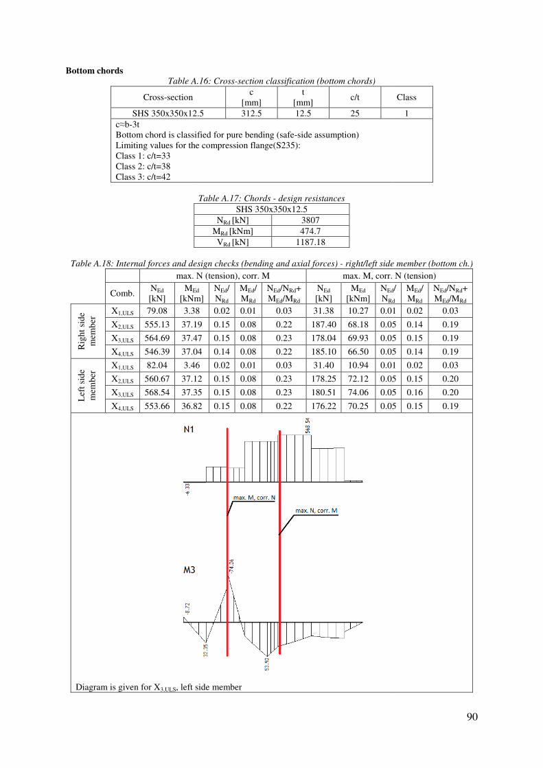
Bottom chords
Table A
Cross-section
SHS 350x350x12.5c≈b-3t Bottom chord is classified for pure Limiting values for the compression flangeClass 1: c/t=33 Class 2: c/t=38 Class 3: c/t=42
Table A.18: Internal forces and design checks (bending and axial forces)
max. N
Comb. NEd
[kN] MEd
[kNm]
Rig
ht s
ide
mem
ber
X1,ULS 79.08 3.38
X2,ULS 555.13 37.19
X3,ULS 564.69 37.47
X4,ULS 546.39 37.04
Lef
t sid
e m
embe
r
X1,ULS 82.04 3.46
X2,ULS 560.67 37.12
X3,ULS 568.54 37.35
X4,ULS 553.66 36.82
Diagram is given for X3,ULS, left side member
A.16: Cross-section classification (bottom chords)
c
[mm] t
[mm] c/t
SHS 350x350x12.5 312.5 12.5 25
Bottom chord is classified for pure bending (safe-side assumption) for the compression flange(S235):
Table A.17: Chords - design resistances
SHS 350x350x12.5 NRd [kN] 3807
MRd [kNm] 474.7 VRd [kN] 1187.18
: Internal forces and design checks (bending and axial forces) - right/left side member (bottom ch.)
max. N (tension), corr. M max. M, corr. N
Ed [kNm]
NEd/ NRd
MEd/ MRd
NEd/NRd+ MEd/MRd
NEd
[kN] MEd
[kNm] NEd
NRd
3.38 0.02 0.01 0.03 31.38 10.27 0.01
37.19 0.15 0.08 0.22 187.40 68.18 0.05
37.47 0.15 0.08 0.23 178.04 69.93 0.05
37.04 0.14 0.08 0.22 185.10 66.50 0.05
3.46 0.02 0.01 0.03 31.40 10.94 0.01
37.12 0.15 0.08 0.23 178.25 72.12 0.05
37.35 0.15 0.08 0.23 180.51 74.06 0.05
36.82 0.15 0.08 0.22 176.22 70.25 0.05
, left side member
90
Class
1
right/left side member (bottom ch.)
max. M, corr. N (tension)
Ed/ Rd
MEd/ MRd
NEd/NRd+ MEd/MRd
0.01 0.02 0.03
0.05 0.14 0.19
0.05 0.15 0.19
0.05 0.14 0.19
0.01 0.02 0.03
0.05 0.15 0.20
0.05 0.16 0.20
0.05 0.15 0.19

Table A.19: Internal forces and design checks (shear)
Member
Right side member Left side member
Table A.20: Internal forces and design checks (bending and axial forces)
max. N
Comb. NEd
[kN] MEd
[kNm]
Rig
ht
supp
orti
ng
beam
L
eft
X1,ULS 135.52 2.48
X2,ULS 517.46 19.05
X3,ULS 538.47 19.57
X4,ULS 497.64 18.58
Lef
t su
ppor
ting
be
am
X1,ULS 141.12 2.33
X2,ULS 564.12 20.50
X3,ULS 588.58 21.01
X4,ULS 541.50 20.02
Diagram is given for X3,ULS, left supporting beam
Table A.21: Internal forces and design checks (shear)
Member
Right supporting beamLeft supporting beam
: Internal forces and design checks (shear) - right/left side member (bottom chord)
Shear forces [kN] X1,ULS X2,ULS X3,ULS X4,ULS VEd,max 20.24 95.65 97.09 94.24 97.09 20.21 99.63 101.20 98.15 101.20
: Internal forces and design checks (bending and axial forces) - right/left suppor. beam (bottom ch.)
max. N (tension), corr. M max. M, corr. N
Ed [kNm]
NEd/ NRd
MEd/ MRd
NEd/NRd+ MEd/MRd
NEd
[kN] MEd
[kNm] NEd
NRd
2.48 0.04 0.01 0.04 43.33 29.27 0.01
19.05 0.14 0.04 0.18 180.34 114.00 0.05
19.57 0.14 0.04 0.18 185.76 115.29 0.05
18.58 0.13 0.04 0.17 175.17 112.90 0.05
2.33 0.04 0.00 0.04 45.86 28.55 0.01
20.50 0.15 0.04 0.19 197.89 114.77 0.05
21.01 0.15 0.04 0.20 204.26 116.11 0.05
20.02 0.14 0.04 0.18 191.83 113.61 0.05
, left supporting beam
: Internal forces and design checks (shear) - right/left supporting beam (bottom chord)
Shear forces [kN] X1,ULS X2,ULS X3,ULS X4,ULS VEd,max
Right supporting beam 36.32 145.87 145.78 146.19 146.19 35.63 147.82 147.37 148.49 148.49
91
right/left side member (bottom chord)
VEd/VRd
0.08 0.09
right/left suppor. beam (bottom ch.)
max. M, corr. N (tension)
Ed/ Rd
MEd/ MRd
NEd/NRd+ MEd/MRd
0.01 0.06 0.07
0.05 0.24 0.29
0.05 0.24 0.29
0.05 0.24 0.28
0.01 0.06 0.07
0.05 0.24 0.29
0.05 0.24 0.30
0.05 0.24 0.29
beam (bottom chord)
VEd/VRd
0.12 0.13

Table A.22: Internal forces and design checks (bending and axial forces)
Comb.
C1
C2
: Internal forces and design checks (bending and axial forces) - connecting beam (bottom chord)
max. N (tension), max. M
Comb. NEd
[kN] MEd
[kNm] NEd/ NRd
MEd/ MRd
NEd/NRd+ MEd/MRd
X1,ULS 102.85 10.58 0.03 0.02 0.05
X2,ULS 494.57 45.67 0.13 0.10 0.23
X3,ULS 518.52 45.27 0.14 0.10 0.23
X4,ULS 480.72 46.14 0.13 0.10 0.22
X1,ULS 122.52 7.13 0.03 0.02 0.05
X2,ULS 548.63 31.73 0.14 0.07 0.21
X3,ULS 504.69 31.43 0.13 0.07 0.20
X4,ULS 593.36 32.07 0.16 0.07 0.22
C1, X3,ULS
C2, X3,ULS
92
connecting beam (bottom chord)

Table A.23: Internal forces and design checks (shear)
Member
C1 C2
Upper chords
Table A
Cross-section
SHS 350x350x12.5c≈b-3t Bottom chord is classified for pure compression (safeLimiting values in compression(S235):Class 1: c/t=33 Class 2: c/t=38 Class 3: c/t=42
Table A.26: Internal forces and design checks (bending and axial forces)
Comb.
Rig
ht s
ide
mem
ber
X
X
X
X
Lef
t sid
e m
embe
r
X
X
X
X
Diagram is given for X
: Internal forces and design checks (shear) - connecting beam (bottom chord)
Shear forces [kN] X1,ULS X2,ULS X3,ULS X4,ULS VEd,max 11.33 44.28 44.99 43.64 44.99 13.28 14.19 14.23 14.19 14.19
A.24: Cross-section classification (upper chords)
c
[mm] t
[mm] c/t
SHS 350x350x12.5 312.5 12.5 25
Bottom chord is classified for pure compression (safe-side assumption) Limiting values in compression(S235):
Table A.25: Chords - design resistances
SHS 350x350x12.5 NRd [kN] 3807
MRd [kNm] 474.7 VRd [kN] 1187.18
: Internal forces and design checks (bending and axial forces) - right/left side member (upper ch.)
max. N (compression), max. M
Comb. NEd
[kN] MEd
[kNm] NEd/ NRd
MEd/ MRd
NEd/NRd+ MEd/MRd
X1,ULS 85.93 12.22 0.02 0.03 0.05
X2,ULS 532.55 129.74 0.14 0.27 0.41
X3,ULS 534.42 131.50 0.14 0.28 0.42
X4,ULS 545.76 128.03 0.14 0.27 0.41
X1,ULS 88.29 12.23 0.02 0.03 0.05
X2,ULS 536.19 129.76 0.14 0.27 0.41
X3,ULS 539.53 131.51 0.14 0.28 0.42
X4,ULS 547.94 128.06 0.14 0.27 0.41
Diagram is given for X4,ULS, left side member
93
connecting beam (bottom chord)
VEd/VRd
0.04 0.01
Class
1
right/left side member (upper ch.)

Table A.27: Internal forces and design checks (shear)
Member
Right side member Left side member
Table A.28: Stability checks
Buckling plane
Section
In-plane 350x350x12.5 1908.0
Out-of-plane 350x350x12.5 6678.0Lcr=0.9Lsys α=0.49 For λ� = 0.2 only cross-sectional checks applyFor out-of-plane buckling is assumed that the axial force is constant between the lateral supports with its maximum value. Interaction (M+N) is not relevant since there is no in
Table A.29: Internal forces and design checks (bending and axial forces)
Comb.
Rig
ht
supp
orti
ng
beam
Lef
t su
ppor
ting
be
am
Diagram is given for X
: Internal forces and design checks (shear) - right/left side member (upper chord)
Shear forces [kN] X1,ULS X2,ULS X3,ULS X4,ULS VEd,max 25.24 163.78 165.13 166.06 166.06 25.31 166.92 165.40 169.12 169.12
: Stability checks - right/left side member (upper chord)
Lsys
[mm] Lcr
[mm] i
[mm] λ� Φ χ N[kN]
1908.0 1717.2 136 0.134
1 3807.0
6678.0 6010.2 136 0.471 0.677 0.859 3270.2
sectional checks apply. assumed that the axial force is constant between the lateral supports with its
Interaction (M+N) is not relevant since there is no in-plane buckling (see 4.1.3.2. for the explanations)
: Internal forces and design checks (bending and axial forces) - right/left suppor. beam (upper ch.)
max. N (compression), max. M
Comb. NEd
[kN] MEd
[kNm] NEd/ NRd
MEd/ MRd
NEd/NRd+ MEd/MRd
X1,ULS 134.91 18.26 0.04 0.04 0.08
X2,ULS 512.95 79.21 0.13 0.17 0.30
X3,ULS 521.05 76.06 0.14 0.16 0.30
X4,ULS 515.36 79.47 0.14 0.17 0.31
X1,ULS 141.86 19.10 0.04 0.04 0.08
X2,ULS 526.53 85.29 0.14 0.18 0.32
X3,ULS 567.35 85.03 0.15 0.18 0.33
X4,ULS 565.87 85.66 0.15 0.18 0.33
Diagram is given for X4,ULS, left supporting beam
94
right/left side member (upper chord)
VEd/VRd
0.14 0.14
right/left side member (upper chord)
Nb,Rd
[kN] NEd,max
[kN] NEd/ Nb,Rd
3807.0 547.94 0.14
3270.2 547.94 0.17
assumed that the axial force is constant between the lateral supports with its
plane buckling (see 4.1.3.2. for the explanations)
right/left suppor. beam (upper ch.)

Table A.30: Internal forces and design checks (shear)
Member
Right supporting beamLeft supporting beam
Table A.31: Stability checks
Buckling plane
Section
In-plane 350x350x12.5 1908.0
Out-of-plane 350x350x12.5 6678.0Lcr=0.9Lsys α=0.49 For λ� = 0.2 only cross-sectional checks apply.For out-of-plane buckling is assumed that the axial force is constant between the lateral supports with its maximum value. Interaction (M+N) is not relevant since
Table A.32: Internal forces and design checks (bending and axial forces)
Comb.
C1
C2
: Internal forces and design checks (shear) - right/left supporting beam (upper chord)
Shear forces [kN] X1,ULS X2,ULS X3,ULS X4,ULS VEd,max
Right supporting beam 19.52 77.78 77.98 77.69 77.98 19.31 79.33 79.47 79.33 79.47
: Stability checks - right/left supporting beam (upper chord)
Lsys
[mm] Lcr
[mm] i
[mm] λ� Φ χ N[kN]
1908.0 1717.2 136 0.134
1 3807.0
6678.0 6010.2 136 0.471 0.677 0.859 3270.2
sectional checks apply. is assumed that the axial force is constant between the lateral supports with its
Interaction (M+N) is not relevant since there is no in-plane buckling (see 4.1.3.2. for the explanations)
: Internal forces and design checks (bending and axial forces) - connecting beam (upper chord)
max. N (compression), max. M
Comb. NEd
[kN] MEd
[kNm] NEd/ NRd
MEd/ MRd
NEd/NRd+ MEd/MRd
X1,ULS 125.68 12.57 0.03 0.03 0.06
X2,ULS 600.07 52.09 0.16 0.11 0.27
X3,ULS 557.06 51.73 0.15 0.11 0.26
X4,ULS 643.87 52.52 0.17 0.11 0.28
X1,ULS 114.97 14.09 0.03 0.03 0.06
X2,ULS 478.52 72.55 0.13 0.15 0.28
X3,ULS 495.22 72.66 0.13 0.15 0.28
X4,ULS 462.56 72.52 0.12 0.15 0.27
C1, X4,ULS
95
right/left supporting beam (upper chord)
VEd/VRd
0.07 0.07
right/left supporting beam (upper chord)
Nb,Rd
[kN] NEd,max
[kN] NEd/ Nb,Rd
3807.0 567.35 0.15
3270.2 567.35 0.17
is assumed that the axial force is constant between the lateral supports with its
plane buckling (see 4.1.3.2. for the explanations)
connecting beam (upper chord)

Table A.33: Internal forces and design checks (shear)
Member
C1 C2
Table A.34
Buckling plane
Section
In-plane 350x350x12.5 3400.0
Out-of-plane 350x350x12.5 3400.0Lcr=0.9Lsys α=0.49 Interaction check (member C1, combination XCmy=1 (bending moment diagram almost rectangular)
kyy=1 �1+(0.24-0.2) 643.87
3807 =1.007
kzy=0 0.17+1.007·0.11=0.281<1 (EN19930.17<1 (EN1993-1-1, equation 6.62, with k
Bracket - diagonal
The diagonal on the right side is relevant
Table A.35
Cross-sectional part
HEB 360, flangeHEB 360, web
Cross-section is classified for pure compressionLimiting values (S235):Class 1: flange c/t=9, web c/t=33Class 2: flange c/t=10, web c/t=38Class 3: flange c/t=14, web c/t=42
C2, X3,ULS
: Internal forces and design checks (shear) - connecting beam (upper chord)
Shear forces [kN] X1,ULS X2,ULS X3,ULS X4,ULS VEd,max 18.14 53.30 53.35 53.37 53.37 13.51 49.46 50.07 48.92 50.07
34: Stability checks - connecting beam (upper chord)
Lsys
[mm] Lcr
[mm] i
[mm] λ� Φ χ N[kN]
3400.0 3060.0 136 0.24 0.539 0.979 3726.4
3400.0 3060.0 136 0.24 0.539 0.979 3726.4
Interaction check (member C1, combination X4,ULS as the most unfavorable case) =1 (bending moment diagram almost rectangular)
007
0.17+1.007·0.11=0.281<1 (EN1993-1-1, equation 6.61) 1, equation 6.62, with kzy=0)
The diagonal on the right side is relevant for the design because it is longer and has higher loading.
35: Cross-section classification (bracket-diagonal)
al part c
[mm] t
[mm] c/t
HEB 360, flange 116.75 22.5 5.19 261 12.5 20.88
section is classified for pure compression Limiting values (S235):
c/t=9, web c/t=33 Class 2: flange c/t=10, web c/t=38 Class 3: flange c/t=14, web c/t=42
96
beam (upper chord)
VEd/VRd
0.04 0.04
Nb,Rd
[kN] NEd,max
[kN] NEd/ Nb,Rd
3726.4 643.87 0.17
3726.4 643.87 0.17
because it is longer and has higher loading.
Class
1 1

97
Table A.36: Compression forces [kN] - bracket (diagonal)
Member X1,ULS X2,ULS X3,ULS X4,ULS NEd,max
Bracket-diagonal 118.25 709.75 710.89 709.37 710.89 Bending moments (resulting from the self-weight) are negligible and will not be considered further.
Table A.37: Bracket (diagonal) - design resistances
HEB 360 NRd [kN] 4244.1
MRd [kNm] 631.21
Table A.38: Design checks (compression + stability) - bracket (diagonal)
Buckling plane Section Lsys
[mm] Lcr
[mm] i
[mm] λ� Φ χ Nb,Rd
[kN] NEd,max
[kN] NEd/ Nb,Rd
In-plane (y-y) HEB 360 3518 3518 154.6 0.242 0.536 0.985 4182.2 710.89 0.17
Out-of-plane (z-z) HEB 360 3518 3518 74.9 0.5 0.699 0.843 3576.2 710.89 0.20 Lcr=Lsys α=0.34 (in-plane buckling) α=0.49 (out-of-plane buckling) Bracket - vertical
Table A.39: Cross-section classification (bracket-vertical)
Cross-sectional part c
[mm] t
[mm] c/t Class
HEB 360, flange 116.75 22.5 5.19 1 HEB 360, web 261 12.5 20.88 1
Cross-section is classified for pure bending (safe-side assumption) Limiting values (S235): Class 1: flange c/t=9, web c/t=72 Class 2: flange c/t=10, web c/t=83 Class 3: flange c/t=14, web c/t=124
Table A.40: Bracket (vertical) - design resistances
HEB 360 NRd [kN] 4244.1
MRd [kNm] 631.21
Table A.41: Internal forces and design checks (bending and axial forces) - bracket (vertical)
max. N (tension), max. M
Comb. NEd
[kN] MEd
[kNm] NEd/ NRd
MEd/ MRd
NEd/NRd+ MEd/MRd
Rig
ht s
ide
vert
ical
X1,ULS 91.03 21.26 0.02 0.03 0.05
X2,ULS 499.81 118.02 0.12 0.19 0.31
X3,ULS 501.75 118.46 0.12 0.19 0.31
X4,ULS 498.45 117.73 0.12 0.19 0.31
Lef
t sid
e ve
rtic
al
X1,ULS 92.70 18.38 0.02 0.03 0.05
X2,ULS 517.25 104.18 0.12 0.17 0.29
X3,ULS 519.07 104.68 0.12 0.17 0.29
X4,ULS 516.02 103.80 0.12 0.16 0.28

Table
Combination X3,ULS is the most unfavorable case in bendingMcr=13819.31 kNm
λ�LT=� 631.21
13819.31=0.214
For λ�LT = 0.4 lateral-torsional buckling check is not necessary Bracket - horizontal
Table A.43
Cross-sectional part
HEA 800, flangeHEA 800, web
Cross-section is classified for bending (safeLimiting values (S235):Class 1: flange c/t=9, web c/t=72Class 2: flange c/t=10, web c/t=83Class 3: flange c/t=14, web c/t=124
Table
Table A.45: Internal forces and design checks (bending and axial forces)
Comb.
Rig
ht s
ide
hori
zont
al X
X
X
X
Lef
t sid
e ho
rizo
ntal
X
X
X
X
Right side vertical, X3,ULS
Table A.42: Stability checks - bracket (vertical)
is the most unfavorable case in bending
torsional buckling check is not necessary
43: Cross-section classification (bracket-horizontal)
al part c
[mm] t
[mm] c/t
HEA 800, flange 112.5 28 4.02 337 15 22.47
section is classified for bending (safe-side assumption) Limiting values (S235): Class 1: flange c/t=9, web c/t=72 Class 2: flange c/t=10, web c/t=83 Class 3: flange c/t=14, web c/t=124
Table A.44: Bracket (horizontal) - design resistances
HEA 800 NRd [kN] 6716.3
MRd [kNm] 2044.27
: Internal forces and design checks (bending and axial forces) - bracket (horizontal)
max. N (tension), max. M
Comb. NEd
[kN] MEd
[kNm] NEd/ NRd
MEd/ MRd
NEd/NRd+ MEd/MRd
X1,ULS 88.35 79.38 0.01 0.04 0.05
X2,ULS 533.36 436.37 0.08 0.21 0.29
X3,ULS 536.93 440.74 0.08 0.22 0.30
X4,ULS 530.31 432.51 0.08 0.21 0.29
X1,ULS 71.53 69.63 0.01 0.03 0.04
X2,ULS 435.94 386.26 0.06 0.19 0.25
X3,ULS 439.78 391.16 0.07 0.19 0.26
X4,ULS 432.56 381.80 0.06 0.19 0.25
98
Class
1 1
bracket (horizontal)

Table
Combination X3,ULS is the most unfavorable case in bendingMcr=27638.3 kNm
λ�LT=�2044.27
27638.3=0.272
For λ�LT = 0.4 lateral-torsional buckling check is not necessary Design of joints
Right/left side
member
Right/left supporting
beam
Connecting beam
Right side horizontal, X3,ULS
Table A.46: Stability checks - bracket (horizontal)
is the most unfavorable case in bending
torsional buckling check is not necessary
Table A.47: Designation - joints
99

100
Table A.48: Design checks - Joint 1 (right/left side member)
Joint 1 (right/left side member) Geometry: T joint Brace 1 Chord Validity limits check
b1/b0=200/350=0.571>0.25 b1/t1=200/6=33.33<35 h1/t1=100/6=16.66<35 Brace 1 cross-section class 1 h0/b0=350/350=1>0.5 h0/b0=350/350=1<2 h1/b1=100/200=0.5=0.5 b0/t0=350/12.5=28<35
SM1 SHS 350x350x12.5
RHS 200x100x6 N0,Ed=0 θ=90° M0,Ed=0 N1,Ed=-154.04 kN T joint resistance N1,Rd=273.3 kN (chord face failure because β<0.85) Joint resistance check N1,Ed/N1,Rd=154.04/273.3=0.564<1
Table A.49: Design checks - Joint 2 (right/left side member)
Joint 2 (right/left side member) Geometry: K gap g=100.7 mm e=-40 mm Brace 1 Brace 2 Chord Validity limits check
b1(2)/b0=200/350=0.571>0.35 b1(2)/b0=200/350=0.571>0.1+0.01·350/12.5 b1/t1=200/6=33.33<35 h1/t1=100/6=16.66<35 b2/t2=200/8=25<35 h2/t2=100/8=12.5<35 Brace 2 cross-section class 1 h0/b0=350/350=1>0.5 h0/b0=350/350=1<2 h1/b1=100/200=0.5=0.5 h2/b2=100/200=0.5=0.5 b0/t0=350/12.5=28<35 g/b0=100.7/350=0.288>0.5(1-0.571) g/b0=100.7/350=0.288<1.5(1-0.571) e=-40 >-0.55·350=-192.5
SM2 SM3 SHS 350x350x12.5
RHS 200x100x6 RHS 200x100x8 N0,Ed=187.3 kN θ=50.68° θ=47.84° M0,Ed=32.54 kNm N1,Ed=83.04 kN N2,Ed=-213.1 kN K joint resistance (brace 1: 83.04 kN, brace 2: -83.04 kN) N1,Rd=706.9 kN (chord face failure is the governing failure mode) N2,Rd=677.4 kN (chord face failure is the governing failure mode) N0,Rd=3924 kN (chord shear failure) Y joint resistance (brace 2: -133.06 kN) N2,Rd=391.8 kN (chord face failure is the governing failure mode) Joint resistance check N1,Ed/N1,Rd=83.04/706.9=0.118<1 N2,Ed/N2,Rd=83.04/677.4+113.06/391.8=0.462<1 N0,Ed/N0,Rd=187.3/3924=0.05<1
Table A.50: Design checks - Joint 3 (right/left side member)
Joint 3 (right/left side member) Geometry: T joint Brace 1 Chord Validity limits check
b1/b0=150/350=0.429>0.25 b1/t1=150/6=25<35 h1/t1=150/6=25<35 Brace 1 cross-section class 1 h0/b0=350/350=1>0.5 h0/b0=350/350=1<2 h1/b1=150/150=1>0.5 h1/b1=150/150=1<2 b0/t0=350/12.5=28<35
SM4 SHS 350x350x12.5
SHS 150x150x6 N0,Ed=180.52 kN θ=90° M0,Ed=-74.6 kNm N1,Ed=-199.83 kN T joint resistance N1,Rd=249.4 kN (chord face failure because β<0.85) Joint resistance check N1,Ed/N1,Rd=199.83/249.4=0.801<1

101
Table A.51: Design checks - Joint 4 (right/left side member)
Joint 4 (right/left side member) Geometry: K gap g=108 mm e=0 mm Brace 1 Brace 2 Chord Validity limits check
b1(2)/b0=200/350=0.571>0.35 b1(2)/b0=200/350=0.571>0.1+0.01·350/12.5 b1/t1=200/8=25<35 h1/t1=100/8=12.5<35 b2/t2=200/6=33.33<35 h2/t2=100/6=16.66<35 Brace 2 cross-section class 1 h0/b0=350/350=1>0.5 h0/b0=350/350=1<2 h1/b1=100/200=0.5=0.5 h2/b2=100/200=0.5=0.5 b0/t0=350/12.5=28<35 g/b0=108/350=0.309>0.5(1-0.571) g/b0=108/350=0.309<1.5(1-0.571)
SM5 SM6 SHS 350x350x12.5
RHS 200x100x8 RHS 200x100x6 N0,Ed=488.81 kN θ=56.48° θ=57.54° M0,Ed=21.78 kNm N1,Ed=256.15 kN N2,Ed=-341.55 kN K joint resistance (forces ratio 75%) N1,Rd=628.6 kN (chord face failure is the governing failure mode) N2,Rd=621.1 kN (chord face failure is the governing failure mode) N0,Rd=3895 kN (chord shear failure) Joint resistance check N1,Ed/N1,Rd=256.15/628.6=0.41<1 N2,Ed/N2,Rd=341.55/621.1=0.55<1 N0,Ed/N0,Rd=488.81/3895=0.13<1
Table A.52: Design checks - Joint 5 (right/left side member)
Joint 5 (right/left side member) Geometry: K gap g=104.1 mm e=0 mm Brace 1 Brace 2 Chord Validity limits check
b1(2)/b0=200/350=0.571>0.35 b1(2)/b0=200/350=0.571>0.1+0.01·350/12.5 b1/t1=200/6=33.33<35 h1/t1=100/6=16.66<35 b2/t2=200/6=33.33<35 h2/t2=100/6=16.66<35 Brace 2 cross-section class 1 h0/b0=350/350=1>0.5 h0/b0=350/350=1<2 h1/b1=100/200=0.5=0.5 h2/b2=100/200=0.5=0.5 b0/t0=350/12.5=28<35 g/b0=104.1/350=0.297>0.5(1-0.571) g/b0=104.1/350=0.297<1.5(1-0.571)
SM7 SM8 SHS 350x350x12.5
RHS 200x100x6 RHS 200x100x6 N0,Ed=568.21 kN θ=57.54° θ=57.54° M0,Ed=37.45 kNm N1,Ed=83.81 kN N2,Ed=-59.15 kN K joint resistance (brace 1: 59.15 kN, brace 2: -59.15 kN) N1,Rd=621.1 kN (chord face failure is the governing failure mode) N2,Rd=621.1 kN (chord face failure is the governing failure mode) N0,Rd=3924 kN (chord shear failure) Y joint resistance (brace 1: 24.66 kN) N1,Rd=334.7 kN (chord face failure is the governing failure mode) Joint resistance check N1,Ed/N1,Rd=59.15/621.1+24.66/334.7=0.169<1 N2,Ed/N2,Rd=59.15/621.18=0.095<1 N0,Ed/N0,Rd=568.21/3924=0.145<1
Table A.53: Design checks - Joint 6 (right/left side member)
Joint 6 (right/left side member) Geometry: K gap g=101.6 mm e=0 mm Brace 1 Brace 2 Chord Validity limits check
b1(2)/b0=200/350=0.571>0.35 b1(2)/b0=200/350=0.571>0.1+0.01·350/12.5 b1/t1=200/6=33.33<35 h1/t1=100/6=16.66<35 Brace 1 cross-section class 1 b2/t2=200/6=33.33<35 h2/t2=100/6=16.66<35 h0/b0=350/350=1>0.5 h0/b0=350/350=1<2 h1/b1=100/200=0.5=0.5 h2/b2=100/200=0.5=0.5 b0/t0=350/12.5=28<35 g/b0=101.6/350=0.290>0.5(1-0.571) g/b0=101.6/350=0.290<1.5(1-0.571)
SM9 SM10 SHS 350x350x12.5
RHS 200x100x6 RHS 200x100x6 N0,Ed=546.07 kN θ=57.54° θ=58.22° M0,Ed=20.18 kNm N1,Ed=-152.64 kN N2,Ed=170.67 kN K joint resistance (forces ratio 89%) N1,Rd=621.1 kN (chord face failure is the governing failure mode) N2,Rd=616.5 kN (chord face failure is the governing failure mode) N0,Rd=3912 kN (chord shear failure) Joint resistance check N1,Ed/N1,Rd=152.64/621.1=0.246<1 N2,Ed/N2,Rd=170.67/616.5=0.277<1 N0,Ed/N0,Rd=546.07/3912=0.140<1

102
Table A.54: Design checks - Joint 7 (right/left side member)
Joint 7 (right/left side member) Geometry: KT overlap λov=(44.95+39.01)% e=30 mm Brace 1 (overlapped - j)
Brace 2 (overlapping - i)
Brace 3 (overlapped - j)
Validity limits check b2/b0=150/350=0.429>0.25 b3/t3=200/10=20<35 h3/t3=200/10=20<35 b3/t3=150/6=25<35 h3/t3=150/6=25<35 Brace 1 cross-section class 1 h0/b0=350/350=1>0.5 h0/b0=350/350=1<2 h1/b1=200/200=1>0.5 h1/b1=200/200=1<2 h2/b2=150/150=1>0.5 h2/b2=150/150=1<2 h3/b3=200/200=1>0.5 h3/b3=200/200=1<2 Chord cross-section class 1 λov>25 %; b2/b1=150/200=0.75 b2/b3=150/200=0.75 e=30<0.25·350=87.5
SM11 SM12 SM13
RHS 200x200x10 RHS 150x150x6 RHS 200x200x10 θ=58.72° θ=90° θ=56.31° N1,Ed=-369.75 kN N2,Ed=17.34 kN N3,Ed=331.76 kN Chord SHS 350x350x12.5 N0,Ed=372.25 kN M0,Ed=23.34 kNm KT joint resistance be,ov=125 mm N2,Rd=741.66 kN (brace failure is the governing failure mode) N1,Rd=1602.52 kN N3,Rd=1602.52 kN Joint resistance check N1,Ed/N1,Rd=369.75/1602.52=0.231<1 N2,Ed/N2,Rd=17.34/741.66=0.023<1 N3,Ed/N3,Rd=331.76/1602.52=0.207<1 λov>80%=> local shear check is necessary 369.75cos58.72°+331.76cos56.31°<VL=1972.0 kN
Table A.55: Design checks - Joint 8 (right/left side member)
Joint 8 (right/left side member) Geometry: N gap g=100.41 mm e=87.5 mm Brace 1 Brace 2 Chord Validity limits check
b1(2)/b0=200/350=0.571>0.35 b1(2)/b0=200/350=0.571>0.1+0.01·350/12.5 b1/t1=200/6=33.33<35 h1/t1=100/6=16.66<35 Brace 1 cross-section class 1 b2/t2=200/6=33.33<35 h2/t2=100/6=16.66<35 h0/b0=350/350=1>0.5 h0/b0=350/350=1<2 h1/b1=100/200=0.5=0.5 h2/b2=100/200=0.5=0.5 b0/t0=350/12.5=28<35 g/b0=100.41/350=0.287>0.5(1-0.571) g/b0=100.41/350=0.287<1.5(1-0.571) e=87.5 =0.25·350=87.5
SM1 SM2 SHS 350x350x12.5
RHS 200x100x6 RHS 200x100x6 N0,Ed=-49.65 kN θ=90° θ=50.68° M0,Ed=0 kNm N1,Ed=-154.04 kN N2,Ed=83.04 kN N joint resistance (brace 1: -64.24 kN, brace 2: 83.04 kN) N1,Rd=524.0 kN (chord face failure is the governing failure mode) N2,Rd=677.4 kN (chord face failure is the governing failure mode) N0,Rd=3921 kN (chord shear failure) T joint resistance (brace 1: -89.8 kN) N1,Rd=273.3 kN (chord face failure is the governing failure mode) Joint resistance check N1,Ed/N1,Rd=64.24/524.0+89.8/273.3=0.451<1 N2,Ed/N2,Rd=83.04/677.4=0.123<1 N0,Ed/N0,Rd=49.65/3921=0.013<1
Table A.56: Design checks - Joint 9 (right/left side member)
Joint 9 (right/left side member) Geometry: KT overlap λov=(25.55+39.19)% e=-60 mm Brace 1 (overlapped - j)
Brace 2 (overlapping - i)
Brace 3 (overlapped - j)
Validity limits check b2/b0=150/350=0.429>0.25 b3/t3=200/8=25<35 h3/t3=100/8=12.5<35 Brace 1 and brace 2 cross-section class 1 h0/b0=350/350=1>0.5 h0/b0=350/350=1<2 h1/b1=100/200=0.5=0.5 h2/b2=150/150=1>0.5 h2/b2=150/150=1<2 h3/b3=100/200=0.5=0.5
SM3 SM4 SM5
RHS 200x100x8 RHS 150x150x6 RHS 200x100x8 θ=47.84° θ=90° θ=56.48° N1,Ed=-213.06 kN N2,Ed=-192.85 kN N3,Ed=253.28 kN Chord SHS 350x350x12.5 N0,Ed=-318.68 kN M0,Ed=32.04 kNm KT joint resistance be,ov=80 mm

103
N2,Rd=614.76 kN (brace failure is the governing failure mode) N1,Rd=790.41 kN N3,Rd=790.41 kN Joint resistance check N1,Ed/N1,Rd=213.06/790.41=0.270<1 N2,Ed/N2,Rd=192.85/614.76=0.314<1 N3,Ed/N3,Rd=253.28/790.41=0.320<1 hj<bj=> local shear check is necessary 213.06cos47.84°+253.28cos56.48°<VL=847.5 kN
Chord cross-section class 1 λov>25 %; b2/b1=150/200=0.75 b2/b3=150/200=0.75 e=-60 >-0.55·350=-192.5
Table A.57: Design checks - Joint 10 (right/left side member)
Joint 10 (right/left side member) Geometry: K gap g=104.1 mm e=0 mm Brace 1 Brace 2 Chord Validity limits check
b1(2)/b0=200/350=0.571>0.35 b1(2)/b0=200/350=0.571>0.1+0.01·350/12.5 b1/t1=200/6=33.33<35 h1/t1=100/6=16.66<35 Brace 1 cross-section class 1 b2/t2=200/6=33.33<35 h2/t2=100/6=16.66<35 h0/b0=350/350=1>0.5 h0/b0=350/350=1<2 h1/b1=100/200=0.5=0.5 h2/b2=100/200=0.5=0.5 b0/t0=350/12.5=28<35 g/b0=104.1/350=0.297>0.5(1-0.571) g/b0=104.1/350=0.297<1.5(1-0.571)
SM6 SM7 SHS 350x350x12.5
RHS 200x100x6 RHS 200x100x6 N0,Ed=-539.52 kN θ=57.54° θ=57.54° M0,Ed=12.20 kNm N1,Ed=-341.55 kN N2,Ed=83.81 kN K joint resistance (brace 1: -83.81 kN, brace 2: 83.81 kN) N1,Rd=621.1 kN (chord face failure is the governing failure mode) N2,Rd=621.1 kN (chord face failure is the governing failure mode) N0,Rd=3923 kN (chord shear failure) Y joint resistance (brace 1: -257.74 kN) N1,Rd=334.7 kN (chord face failure is the governing failure mode) Joint resistance check N1,Ed/N1,Rd=83.81/621.1+257.74/334.7=0.905<1 N2,Ed/N2,Rd=82.81/621.1=0.133<1 N0,Ed/N0,Rd=539.52/3923=0.138<1
Table A.58: Design checks - Joint 11 (right/left side member)
Joint 11 (right/left side member) Geometry: K gap g=104.1 mm e=0 mm Brace 1 Brace 2 Chord Validity limits check
b1(2)/b0=200/350=0.571>0.35 b1(2)/b0=200/350=0.571>0.1+0.01·350/12.5 b1/t1=200/6=33.33<35 h1/t1=100/6=16.66<35 b2/t2=200/6=33.33<35 h2/t2=100/6=16.66<35 Brace 1 and brace 2: cross-section class 1 h0/b0=350/350=1>0.5 h0/b0=350/350=1<2 h1/b1=100/200=0.5=0.5 h2/b2=100/200=0.5=0.5 b0/t0=350/12.5=28<35 g/b0=104.1/350=0.297>0.5(1-0.571) g/b0=104.1/350=0.297<1.5(1-0.571)
SM8 SM9 SHS 350x350x12.5
RHS 200x100x6 RHS 200x100x6 N0,Ed=-532.55 kN θ=57.54° θ=57.54° M0,Ed=0 kNm N1,Ed=-46.36 kN N2,Ed=-150.67 kN Unidirectional K joint resistance beq=(200+200)/2=200 mm heq=100/sin57.57°+104.1+100/sin57.57°=341.12 mm β=200/350=0.571 (chord face failure is the governing mode) Neq,Rd=391.15 kN N1,Rd=109.07 kN N2,Rd=354.50 kN Joint resistance check N1,Ed/N1,Rd=46.36/109.07=0.425<1 N2,Ed/N2,Rd=150.67/354.50=0.425<1

104
Table A.59: Design checks - Joint 12 (right/left side member)
Joint 12 (right/left side member) Geometry: K gap g=88 mm e=40 mm Brace 1 Brace 2 Chord Validity limits check
b1(2)/b0=200/350=0.571>0.35 b1(2)/b0=200/350=0.571>0.1+0.01·350/12.5 b1/t1=200/6=33.33<35 h1/t1=100/6=16.66<35 b2/t2=200/10=20<35 h2/t2=200/10=20<35 Brace 1 cross-section class 1 h0/b0=350/350=1>0.5 h0/b0=350/350=1<2 h1/b1=100/200=0.5=0.5 h2/b2=200/200=1>0.5 h2/b2=200/200=1<2 b0/t0=350/12.5=28<35 g/b0=88/350=0.251>0.5(1-0.571) g/b0=88/350=0.251<1.5(1-0.571) e=40 <0.25·350=87.5
SM10 SM11 SHS 350x350x12.5
RHS 200x100x6 SHS 200x200x10 N0,Ed=-486.28 kN θ=58.22° θ=58.72° M0,Ed=-4.85 kNm N1,Ed=170.67 kN N2,Ed=-369.75 kN K joint resistance (brace 1: 170.67 kN, brace 2: -170.67 kN) N1,Rd=719.2 kN (chord face failure is the governing failure mode) N2,Rd=715.4 kN (chord face failure is the governing failure mode) N0,Rd=3912 kN (chord shear failure) Y joint resistance (brace 1: -199.08 kN) N2,Rd=396.6 kN (chord face failure is the governing failure mode) Joint resistance check N1,Ed/N1,Rd=170.67/719.2=0.237<1 N2,Ed/N2,Rd=170.67/715.4+199.08/396.6=0.741<1 N0,Ed/N0,Rd=486.28/3912=0.124<1
Table A.60: Design checks - Joint 13 (right/left side member)
Joint 13 (right/left side member) Geometry: N overlap λov=52.34 % e=0 mm Brace 1 (overlapped - j)
Brace 2 (overlapping - i)
Chord Validity limits check b2/b0=150/350=0.429>0.25 b1/t1=200/10=20<35 h1/t1=200/10=20<35 Brace 2 cross-section class 1 h0/b0=350/350=1>0.5 h0/b0=350/350=1<2 h1/b1=200/200=1>0.5 h1/b1=200/200=1<2 h2/b2=150/150=1>0.5 h2/b2=150/150=1<2 Chord cross-section class 1 λov>25 % b2/b1=150/200=0.75
SM13 SM14 SHS 350x350x12.5
SHS 200x200x10 RHS 150x150x6 N0,Ed=-212.28 kN θ=56.31° θ=90° M0,Ed=-9.13 kNm N1,Ed=339.53 kN N2,Ed=-175.77 kN N joint resistance beff=111.61 mm be,ov=125 mm N2,Rd=722.78 kN (brace failure is the governing failure mode) N1,Rd=1561.72 kN Joint resistance check N1,Ed/N1,Rd=339.53/1561.72=0.217<1 N2,Ed/N2,Rd=175.77/722.78=0.243<1 hi=bi, hj=bj, λov<60% => local shear check not necessary
Table A.61: Design checks - Joint 1 (right/left supporting beam)
Joint 1 (right/left supporting beam) Geometry: T joint Brace 1 Chord Validity limits check
b1/b0=200/350=0.571>0.25 b1/t1=200/6=33.33<35 h1/t1=100/6=16.66<35 h0/b0=350/350=1>0.5 h0/b0=350/350=1<2 h1/b1=100/200=0.5=0.5 b0/t0=350/12.5=28<35
SB1 SHS 350x350x12.5
RHS 200x100x6 N0,Ed=20.02 kN θ=90° M0,Ed=9.86 kNm N1,Ed=104.29 kN T joint resistance N1,Rd=273.3 kN (chord face failure because β<0.85) Joint resistance check N1,Ed/N1,Rd=104.29/273.3=0.382<1

105
Table A.62: Design checks - Joint 2 (right/left supporting beam)
Joint 2 (right/left supporting beam) Geometry: KT overlap λov=(25.0+62.5)% e=-65 mm Brace 1 (overlapped - j)
Brace 2 (overlapping - i)
Brace 3 (overlapped - j)
Validity limits check b1(2)/b0=200/350=0.571>0.25 Brace , brace 2 and brace 3: cross-section class 1 h0/b0=350/350=1>0.5 h0/b0=350/350=1<2 h1/b1=100/200=0.5=0.5 h2/b2=150/150=1>0.5 h2/b2=150/150=1<2 h3/b3=100/200=0.5=0.5 b0/t0=350/12.5=28<35 λov>25 % b2/b1=150/200=0.75 b2/b3=150/200=0.75
SB2 SB3 SB4
RHS 200x100x6 RHS 150x150x6 RHS 200x100x6 θ=50.22° θ=90° θ=47.23° N1,Ed=-87.71 kN N2,Ed=-130.28 kN N3,Ed=-370.95 kN Chord SHS 350x350x12.5 N0,Ed=204.27 kN M0,Ed=-116.11 kNm Unidirectional KT joint resistance beq=(200+200+150)/3=183.33 mm ; heq=326.5 mm β=183.33/350=0.524 (chord face failure is the governing mode) Stiffening is necessary. Plate tp=15 mm, bp=350 mm is used to reinforce the chord face. βp=0.524; ηp=0.933 Neq,Rd=513.83 kN N1,Rd=95.58 kN; N2,Rd=141.97 kN; N3,Rd=404.23 kN Joint resistance check N1,Ed/N1,Rd=87.71/95.58=0.918<1 N2,Ed/N2,Rd=130.28/141.97=0.918<1 N3,Ed/N3,Rd=370.95/404.23=0.918<1
Table A.63: Design checks - Joint 3 (right/left supporting beam)
Joint 3 (right/left supporting beam) Geometry: T joint Brace 1 Chord Validity limits check
b1/b0=150/350=0.429>0.25 b1/t1=150/6=25<35 h1/t1=150/6=25<35 h0/b0=350/350=1>0.5 h0/b0=350/350=1<2 h1/b1=150/150=1>0.5 h1/b1=150/150=1<2 b0/t0=350/12.5=28<35
SB5 SHS 350x350x12.5
SHS 150x150x6 N0,Ed=191.62 kN θ=90° M0,Ed=70.62 kNm N1,Ed=72.72 kN T joint resistance N1,Rd=249.4 kN (chord face failure because β<0.85) Joint resistance check N1,Ed/N1,Rd=72.72/249.4=0.292<1
Table A.64: Design checks - Joint 4 (right/left supporting beam)
Joint 4 (right/left supporting beam) Geometry: K gap g=120.2 mm e=0 mm Brace 1 Brace 2 Chord Validity limits check
b1/b0=200/350=0.571>0.35 b1/b0=200/350=0.571>0.1+0.01·350/12.5 b2/b0=160/350=0.457>0.35 b2/b0=160/350=0.457>0.1+0.01·350/12.5 b1/t1=200/6=33.33<35 h1/t1=100/6=16.66<35 b2/t2=160/5=32<35 h2/t2=80/5=16<35 Brace 2 cross-section class 1 h0/b0=350/350=1>0.5 h0/b0=350/350=1<2 h1/b1=100/200=0.5=0.5 h2/b2=80/160=0.5=0.5 b0/t0=350/12.5=28<35 g/b0=120.2/350=0.343>0.5(1-0.457) g/b0=120.2/350=0.343<1.5(1-0.457)
SB6 SB7 SHS 350x350x12.5
RHS 200x100x6 RHS 160x80x5 N0,Ed=388.19 kN θ=56.38° θ=57.54° M0,Ed=3.27 kNm N1,Ed=208.33 kN N2,Ed=-110.72 kN K joint resistance (brace 1: 110.72 kN, brace 2: -110.72 kN) N1,Rd=566.4 kN (chord face failure is the governing failure mode) N2,Rd=520.4 kN (chord face failure is the governing failure mode) N0,Rd=3905 kN (chord shear failure) Y joint resistance (brace 1: 97.61 kN) N1,Rd=340.0 kN (chord face failure is the governing failure mode) Joint resistance check N1,Ed/N1,Rd=110.72/566.4+97.61/340.0=0.483<1 N2,Ed/N2,Rd=110.72/520.4=0.213<1 N0,Ed/N0,Rd=388.19/3905=0.099<1

106
Table A.65: Design checks - Joint 5 (right/left supporting beam)
Joint 5 (right/left supporting beam) Geometry: K gap g=127.8 mm e=0 mm Brace 1 Brace 2 Chord Validity limits check
b1(2)/b0=160/350=0.457>0.35 b1(2)/b0=160/350=0.457>0.1+0.01·350/12.5 b1/t1=160/5=32<35 h1/t1=80/5=16<35 b2/t2=160/5=32<35 h2/t2=80/5=16<35 Brace 2 cross-section class 1 h0/b0=350/350=1>0.5 h0/b0=350/350=1<2 h1/b1=80/160=0.5=0.5 h2/b2=80/160=0.5=0.5 b0/t0=350/12.5=28<35 g/b0=127.8/350=0.365>0.5(1-0.457) g/b0=127.8/350=0.365<1.5(1-0.457)
SB8 SB9 SHS 350x350x12.5
RHS 160x80x5 RHS 160x80x5 N0,Ed=493.35 kN θ=57.54° θ=57.54° M0,Ed=12.36 kNm N1,Ed=100.15 kN N2,Ed=-95.20 kN K joint resistance (forces ratio 95%) N1,Rd=496.9 kN (chord face failure is the governing failure mode) N2,Rd=496.9 kN (chord face failure is the governing failure mode) N0,Rd=3921 kN (chord shear failure) Joint resistance check N1,Ed/N1,Rd=100.15/496.9=0.202<1 N2,Ed/N2,Rd=95.2/496.9=0.192<1 N0,Ed/N0,Rd=493.35/3921=0.126<1
Table A.66: Design checks - Joint 6 (right/left supporting beam)
Joint 6 (right/left supporting beam) Geometry: K gap g=127.8 mm e=0 mm Brace 1 Brace 2 Chord Validity limits check
b1(2)/b0=160/350=0.457>0.35 b1(2)/b0=160/350=0.457>0.1+0.01·350/12.5 b1/t1=160/5=32<35 h1/t1=80/5=16<35 b2/t2=160/5=32<35 h2/t2=80/5=16<35 Brace 2 cross-section class 1 h0/b0=350/350=1>0.5 h0/b0=350/350=1<2 h1/b1=80/160=0.5=0.5 h2/b2=80/160=0.5=0.5 b0/t0=350/12.5=28<35 g/b0=127.8/350=0.365>0.5(1-0.457) g/b0=127.8/350=0.365<1.5(1-0.457)
SB10 SB11 SHS 350x350x12.5
RHS 160x80x5 RHS 160x80x5 N0,Ed=588.36 kN θ=57.54° θ=57.54° M0,Ed=21.11 kNm N1,Ed=87.92 kN N2,Ed=-88.30 kN K joint resistance (forces ratio 99.5%) N1,Rd=496.9 kN (chord face failure is the governing failure mode) N2,Rd=496.9 kN (chord face failure is the governing failure mode) N0,Rd=3922 kN (chord shear failure) Joint resistance check N1,Ed/N1,Rd=87.92/496.9=0.177<1 N2,Ed/N2,Rd=88.3/496.9=0.178<1 N0,Ed/N0,Rd=588.36/3922=0.150<1
Table A.67: Design checks - Joint 7 (right/left supporting beam)
Joint 7 (right/left supporting beam) Geometry: KT overlap λov=(25.0+62.5)% e=-25 mm Brace 1 (overlapped - j)
Brace 2 (overlapping - i)
Brace 3 (overlapped - j)
Validity limits check b2/b0=150/350=0.429>0.25 Brace 1 and brace 2 cross-section class 1 b3/t3=200/10=20<35 h3/t3=200/10=20<35 h0/b0=350/350=1>0.5 h0/b0=350/350=1<2 h1/b1=100/200=0.5=0.5 h2/b2=150/150=1>0.5 h2/b2=150/150=1<2 h3/b3=200/200=1>0.5 h3/b3=200/200=1<2 Chord cross-section class 1 λov>25 %; b2/b1=150/200=0.75 b2/b3=150/200=0.75 e=-25>-0.55·350=-192.5
SB12 SB13 SB14
RHS 200x100x6 RHS 150x150x6 RHS 200x200x10 θ=57.11° θ=90° θ=55.70° N1,Ed=-5.89 kN N2,Ed=-132.63 kN N3,Ed=278.92 kN Chord SHS 350x350x12.5 N0,Ed=541.18 kN M0,Ed=19.98 kNm KT joint resistance be,ov,1=45 mm be,ov,2=125 mm N2,Rd=628.86 kN (brace failure is the governing failure mode) N1,Rd= 628.86 kN N3,Rd=1358.79 kN Joint resistance check N1,Ed/N1,Rd=5.89/628.86=0.009<1

107
N2,Ed/N2,Rd=132.63/628.86=0.211<1 N3,Ed/N3,Rd=278.92/1358.79=0.205<1 h1<bj, λov>80%=> local shear check is necessary 5.89cos57.11°+278.92cos55.70°<VL=1303.5 kN
Table A.68: Design checks - Joint 8 (right/left supporting beam)
Joint 8 (right/left supporting beam) Geometry: N overlap λov=37.10 % e=0 mm Brace 1 (overlapped - j)
Brace 2 (overlapping - i)
Chord Validity limits check b2/b0=150/350=0.429>0.25 Brace 1 and brace 2 cross-section class 1 h0/b0=350/350=1>0.5 h0/b0=350/350=1<2 h1/b1=200/200=1>0.5 h1/b1=200/200=1<2 h2/b2=150/150=1>0.5 h2/b2=150/150=1<2 Chord cross-section class 1 λov>25 % b2/b1=150/200=0.75
SM15 SM16 SHS 350x350x12.5
SHS 200x200x10 RHS 150x150x6 N0,Ed=372.01 kN θ=49.09° θ=90° M0,Ed=0 kNm N1,Ed=-654.62 kN N2,Ed=-18.09 kN N joint resistance beff=111.61 mm be,ov=125 mm N2,Rd=613.65 kN (brace failure is the governing failure mode) N1,Rd=1325.91 kN Joint resistance check N1,Ed/N1,Rd=654.62/1325.91=0.494<1 N2,Ed/N2,Rd=18.09/613.65=0.029<1 hi=bi, hj=bj, λov<60% => local shear check not necessary
Table A.69: Design checks - Joint 9 (right/left supporting beam)
Joint 9 (right/left supporting beam) Geometry: N gap g=103.5 mm e=87.5 mm Brace 1 Brace 2 Chord Validity limits check
b1(2)/b0=200/350=0.571>0.35 b1(2)/b0=200/350=0.571>0.1+0.01·350/12.5 b1/t1=200/6=33.33<35 h1/t1=100/6=16.66<35 b2/t2=200/6=33.33<35 h2/t2=100/6=16.66<35 Brace 1 cross-section class 1 h0/b0=350/350=1>0.5 h0/b0=350/350=1<2 h1/b1=100/200=0.5=0.5 h2/b2=100/200=0.5=0.5 b0/t0=350/12.5=28<35 g/b0=103.5/350=0.296>0.5(1-0.571) g/b0=103.5/350=0.296<1.5(1-0.571) e=87.5 =0.25·350=87.5
SB1 SB2 SHS 350x350x12.5
RHS 200x100x6 RHS 200x100x6 N0,Ed=58.31 kN θ=90° θ=50.22° M0,Ed=0 kNm N1,Ed=104.29 kN N2,Ed=-99.93 kN N joint resistance (brace 1: 76.34 kN, brace 2: -99.33 kN) N1,Rd=681.9 kN (chord face failure is the governing failure mode) N2,Rd=524.0kN (chord face failure is the governing failure mode) N0,Rd=3924 kN (chord shear failure) T joint resistance (brace 1: 27.95 kN) N1,Rd=273.3 kN (chord face failure is the governing failure mode) Joint resistance check N1,Ed/N1,Rd=76.34/681.9+27.95/273.3=0.214<1 N2,Ed/N2,Rd=99.33/524.0=0.190<1 N0,Ed/N0,Rd=58.31/3924=0.015<1
Table A.70: Design checks - Joint 10 (right/left supporting beam)
Joint 10 (right/left supporting beam) Geometry: T joint Brace 1 Chord Validity limits check
b1/b0=150/350=0.429>0.25 b1/t1=150/6=25<35 h1/t1=150/6=25<35 Brace 1 cross-section class 1 h0/b0=350/350=1>0.5 h0/b0=350/350=1<2 h1/b1=150/150=1>0.5 h1/b1=150/150=1<2 b0/t0=350/12.5=28<35
SB3 SHS 350x350x12.5
SHS 150x150x6 N0,Ed=-51.43 kN θ=90° M0,Ed=63.67 kNm N1,Ed=-130.28 kN T joint resistance N1,Rd=249.4 kN (chord face failure because β<0.85) Joint resistance check N1,Ed/N1,Rd=130.28/249.4=0.522<1

108
Table A.71: Design checks - Joint 11 (right/left supporting beam)
Joint 11 (right/left supporting beam) Geometry: KT overlap λov=(27.57+41.27)% e=-65 mm Brace 1 (overlapped - j)
Brace 2 (overlapping - i)
Brace 3 (overlapped - j)
Validity limits check b2/b0=150/350=0.429>0.25 Brace 1 cross-section class 1 b2/t2=150/6=25<35 h2/t2=150/6=25<35 b3/t3=200/6=33.33<35 h3/t3=100/6=16.66<35 h0/b0=350/350=1>0.5 h0/b0=350/350=1<2 h1/b1=100/200=0.5=0.5 h2/b2=150/150=1>0.5 h2/b2=150/150=1<2 h3/b3=100/200=0.5=0.5 Chord cross-section class 1 λov>25 %; b2/b1=150/200=0.75 b2/b3=150/200=0.75 e=-65 >-0.55·350=-192.5
SB4 SB5 SB6
RHS 200x100x6 RHS 150x150x6 RHS 200x100x6 θ=47.23° θ=90° θ=56.38° N1,Ed=-370.95 kN N2,Ed=67.6 kN N3,Ed=208.83 kN Chord SHS 350x350x12.5 N0,Ed=-308.73 kN M0,Ed=-35.21 kNm KT joint resistance be,ov=45 mm N2,Rd=516.06 kN (brace failure is the governing failure mode) N1,Rd=516.06 kN N3,Rd=516.06 kN Joint resistance check N1,Ed/N1,Rd=370.95/516.06=0.719<1 N2,Ed/N2,Rd=67.6/516.06=0.131<1 N3,Ed/N3,Rd=208.83/516.06=0.405<1 hj<bj=> local shear check is necessary 370.95cos47.23°+208.83cos56.38°<VL=852.37 kN
Table A.72: Design checks - Joint 12 (right/left supporting beam)
Joint 12 (right/left supporting beam) Geometry: K gap g=127.8 mm e=0 mm Brace 1 Brace 2 Chord Validity limits check
b1(2)/b0=160/350=0.457>0.35 b1(2)/b0=160/350=0.457>0.1+0.01·350/12.5 b1/t1=160/5=32<35 h1/t1=80/5=16<35 Brace 1 cross-section class 1 b2/t2=160/5=32<35 h2/t2=80/5=16<35 h0/b0=350/350=1>0.5 h0/b0=350/350=1<2 h1/b1=80/160=0.5=0.5 h2/b2=80/160=0.5=0.5 b0/t0=350/12.5=28<35 g/b0=127.8/350=0.365>0.5(1-0.457) g/b0=127.8/350=0.365<1.5(1-0.457)
SB7 SB8 SHS 350x350x12.5
RHS 160x80x5 RHS 160x80x5 N0,Ed=-421.56 kN θ=57.54° θ=57.54° M0,Ed=-11.75 kNm N1,Ed=-110.72 kN N2,Ed=100.15 kN K joint resistance (forces ratio 90%) N1,Rd=496.9 kN (chord face failure is the governing failure mode) N2,Rd=496.9 kN (chord face failure is the governing failure mode) N0,Rd=3921 kN (chord shear failure) Joint resistance check N1,Ed/N1,Rd=110.72/496.9=0.223<1 N2,Ed/N2,Rd=100.15/496.9=0.202<1 N0,Ed/N0,Rd=421.56/3921=0.108<1
Table A.73: Design checks - Joint 13 (right/left supporting beam)
Joint 13 (right/left supporting beam) Geometry: K gap g=127.8 mm e=0 mm Brace 1 Brace 2 Chord Validity limits check
b1(2)/b0=160/350=0.457>0.35 b1(2)/b0=160/350=0.457>0.1+0.01·350/12.5 b1/t1=160/5=32<35 h1/t1=80/5=16<35 Brace 1 cross-section class 1 b2/t2=160/5=32<35 h2/t2=80/5=16<35 h0/b0=350/350=1>0.5 h0/b0=350/350=1<2 h1/b1=80/160=0.5=0.5 h2/b2=80/160=0.5=0.5
SB9 SB10 SHS 350x350x12.5
RHS 160x80x5 RHS 160x80x5 N0,Ed=-519.51 kN θ=57.54° θ=57.54° M0,Ed=-12.38 kNm N1,Ed=-95.20 kN N2,Ed=87.92 kN K joint resistance (forces ratio 92%) N1,Rd=496.9 kN (chord face failure is the governing failure mode) N2,Rd=496.9 kN (chord face failure is the governing failure mode) N0,Rd=3922 kN (chord shear failure) Joint resistance check N1,Ed/N1,Rd=95.20/496.9=0.192<1 N2,Ed/N2,Rd=87.92/496.9=0.177<1

109
N0,Ed/N0,Rd=519.51/3922=0.132<1
b0/t0=350/12.5=28<35 g/b0=127.8/350=0.365>0.5(1-0.457) g/b0=127.8/350=0.365<1.5(1-0.457)
Table A.74: Design checks - Joint 14 (right/left supporting beam)
Joint 14 (right/left supporting beam) Geometry: K gap g=117.5 mm e=0 mm Brace 1 Brace 2 Chord Validity limits check
b1/b0=160/350=0.457>0.35 b1/b0=160/350=0.457>0.1+0.01·350/12.5 b2/b0=200/350=0.571>0.35 b2/b0=200/350=0.571>0.1+0.01·350/12.5 b1/t1=160/5=32<35 h1/t1=80/5=16<35 Brace 1 cross-section class 1 b2/t2=200/6=33.33<35 h2/t2=100/6=16.66<35 h0/b0=350/350=1>0.5 h0/b0=350/350=1<2 h1/b1=80/160=0.5=0.5 h2/b2=8100/200=0.5=0.5 b0/t0=350/12.5=28<35 g/b0=117.5/350=0.336>0.5(1-0.457) g/b0=127.8/350=0.336<1.5(1-0.457)
SB11 SB12 SHS 350x350x12.5
RHS 160x80x5 RHS 200x100x6 N0,Ed=-567.33 kN θ=57.54° θ=57.11° M0,Ed=-17.96 kNm N1,Ed=-88.33 kN N2,Ed=1.46 kN Y joint resistance (Force in Brace 2≈0) N1,Rd=279.7 kN (chord face failure is the governing failure mode) Joint resistance check N1,Ed/N1,Rd=88.33/279.7=0.316<1
Table A.75: Design checks - Joint 15 (right/left supporting beam)
Joint 15 (right/left supporting beam) Geometry: KT overlap λov=(42.01+25.57)% e=20 mm Brace 1 (overlapped - j)
Brace 2 (overlapping - i)
Brace 3 (overlapped - j)
Validity limits check b2/b0=150/350=0.429>0.25 b1/t1=200/10=20<35 h1/t1=200/10=20<35 b2/t2=150/6=25<35 h2/t2=150/6=25<35 Brace 3 cross-section class 1 h0/b0=350/350=1>0.5 h0/b0=350/350=1<2 h1/b1=200/200=1<0.5 h1/b1=200/200=1<2 h2/b2=150/150=1>0.5 h2/b2=150/150=1<2 h3/b3=200/200=1<0.5 h3/b3=200/200=1<2 Chord cross-section class 1 λov>25 %; b2/b1=150/200=0.75 b2/b3=150/200=0.75 e=20<0.25·350=87.5
SB14 SB15 SB16
RHS 200x200x10 RHS 150x150x6 RHS 200x200x10 θ=55.7° θ=90° θ=49.09° N1,Ed=278.92 kN N2,Ed=184.23 kN N3,Ed=-654.62 kN Chord SHS 350x350x12.5 N0,Ed=-565.83 kN M0,Ed=-21.57 kNm KT joint resistance be,ov=125 mm N2,Rd=741.66 kN (brace failure is the governing failure mode) N1,Rd=1602.52 kN N3,Rd=1602.52 kN Joint resistance check N1,Ed/N1,Rd=278.92/1602.52=0.174<1 N2,Ed/N2,Rd=184.23/741.66=0.248<1 N3,Ed/N3,Rd=654.62/1602.52=0.408<1 hi=bi, hj=bj, λov<80% => local shear check not necessary
Table A.76: Design checks - Joint 16 (right/left supporting beam)
Joint 16 (right/left supporting beam) Geometry: T joint Brace 1 Chord Validity limits check
b1/b0=150/350=0.429>0.25 b1/t1=150/6=25<35 h1/t1=150/6=25<35 Brace 1 cross-section class 1
SB16 SHS 350x350x12.5
SHS 150x150x6 N0,Ed=0kN θ=90° M0,Ed=0 kNm N1,Ed=-19.62 kN
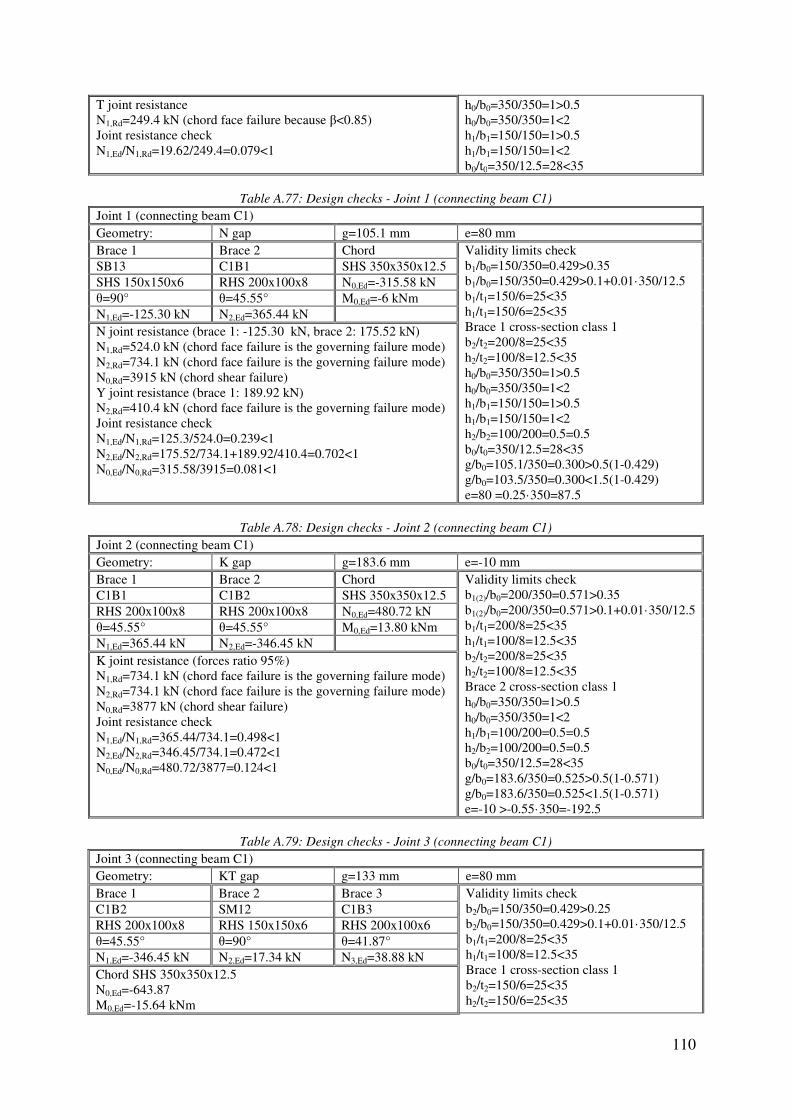
110
T joint resistance N1,Rd=249.4 kN (chord face failure because β<0.85) Joint resistance check N1,Ed/N1,Rd=19.62/249.4=0.079<1
h0/b0=350/350=1>0.5 h0/b0=350/350=1<2 h1/b1=150/150=1>0.5 h1/b1=150/150=1<2 b0/t0=350/12.5=28<35
Table A.77: Design checks - Joint 1 (connecting beam C1)
Joint 1 (connecting beam C1) Geometry: N gap g=105.1 mm e=80 mm Brace 1 Brace 2 Chord Validity limits check
b1/b0=150/350=0.429>0.35 b1/b0=150/350=0.429>0.1+0.01·350/12.5 b1/t1=150/6=25<35 h1/t1=150/6=25<35 Brace 1 cross-section class 1 b2/t2=200/8=25<35 h2/t2=100/8=12.5<35 h0/b0=350/350=1>0.5 h0/b0=350/350=1<2 h1/b1=150/150=1>0.5 h1/b1=150/150=1<2 h2/b2=100/200=0.5=0.5 b0/t0=350/12.5=28<35 g/b0=105.1/350=0.300>0.5(1-0.429) g/b0=103.5/350=0.300<1.5(1-0.429) e=80 =0.25·350=87.5
SB13 C1B1 SHS 350x350x12.5
SHS 150x150x6 RHS 200x100x8 N0,Ed=-315.58 kN θ=90° θ=45.55° M0,Ed=-6 kNm N1,Ed=-125.30 kN N2,Ed=365.44 kN N joint resistance (brace 1: -125.30 kN, brace 2: 175.52 kN) N1,Rd=524.0 kN (chord face failure is the governing failure mode) N2,Rd=734.1 kN (chord face failure is the governing failure mode) N0,Rd=3915 kN (chord shear failure) Y joint resistance (brace 1: 189.92 kN) N2,Rd=410.4 kN (chord face failure is the governing failure mode) Joint resistance check N1,Ed/N1,Rd=125.3/524.0=0.239<1 N2,Ed/N2,Rd=175.52/734.1+189.92/410.4=0.702<1 N0,Ed/N0,Rd=315.58/3915=0.081<1
Table A.78: Design checks - Joint 2 (connecting beam C1)
Joint 2 (connecting beam C1) Geometry: K gap g=183.6 mm e=-10 mm Brace 1 Brace 2 Chord Validity limits check
b1(2)/b0=200/350=0.571>0.35 b1(2)/b0=200/350=0.571>0.1+0.01·350/12.5 b1/t1=200/8=25<35 h1/t1=100/8=12.5<35 b2/t2=200/8=25<35 h2/t2=100/8=12.5<35 Brace 2 cross-section class 1 h0/b0=350/350=1>0.5 h0/b0=350/350=1<2 h1/b1=100/200=0.5=0.5 h2/b2=100/200=0.5=0.5 b0/t0=350/12.5=28<35 g/b0=183.6/350=0.525>0.5(1-0.571) g/b0=183.6/350=0.525<1.5(1-0.571) e=-10 >-0.55·350=-192.5
C1B1 C1B2 SHS 350x350x12.5
RHS 200x100x8 RHS 200x100x8 N0,Ed=480.72 kN θ=45.55° θ=45.55° M0,Ed=13.80 kNm N1,Ed=365.44 kN N2,Ed=-346.45 kN K joint resistance (forces ratio 95%) N1,Rd=734.1 kN (chord face failure is the governing failure mode) N2,Rd=734.1 kN (chord face failure is the governing failure mode) N0,Rd=3877 kN (chord shear failure) Joint resistance check N1,Ed/N1,Rd=365.44/734.1=0.498<1 N2,Ed/N2,Rd=346.45/734.1=0.472<1 N0,Ed/N0,Rd=480.72/3877=0.124<1
Table A.79: Design checks - Joint 3 (connecting beam C1)
Joint 3 (connecting beam C1) Geometry: KT gap g=133 mm e=80 mm Brace 1 Brace 2 Brace 3 Validity limits check
b2/b0=150/350=0.429>0.25 b2/b0=150/350=0.429>0.1+0.01·350/12.5 b1/t1=200/8=25<35 h1/t1=100/8=12.5<35 Brace 1 cross-section class 1 b2/t2=150/6=25<35 h2/t2=150/6=25<35
C1B2 SM12 C1B3
RHS 200x100x8 RHS 150x150x6 RHS 200x100x6 θ=45.55° θ=90° θ=41.87° N1,Ed=-346.45 kN N2,Ed=17.34 kN N3,Ed=38.88 kN Chord SHS 350x350x12.5 N0,Ed=-643.87 M0,Ed=-15.64 kNm

111
Y joint resistance (because: N1,Ed>>N2,Ed and N1,Ed>>N3,Ed) N1,Rd=410.4 kN (chord face failure is the governing failure mode) Joint resistance check N1,Ed/N1,Rd=346.45/410.4=0.844<1
b3/t3=200/6=33.33<35 h3/t3=100/6=16.66<35 h0/b0=350/350=1>0.5 h0/b0=350/350=1<2 h1/b1=100/200=0.5=0.5 h2/b2=150/150=1>0.5 h2/b2=150/150=1<2 h3/b3=100/200=0.5=0.5 b0/t0=350/12.5=28<35 g/b0=133/350=0.380>0.5(1-0.429) g/b0=133/350=0.380<1.5(1-0.429) e=80 <0.25·350=87.5
Table A.80: Design checks - Joint 4 (connecting beam C1)
Joint 4 (connecting beam C1) Geometry: K gap g=118 mm e=-55 mm Brace 1 Brace 2 Chord Validity limits check
b1(2)/b0=200/350=0.571>0.35 b1(2)/b0=200/350=0.571>0.1+0.01·350/12.5 b1/t1=200/6=33.33<35 h1/t1=100/6=16.66<35 b2/t2=200/6=33.33<35 h2/t2=100/6=16.66<35 h0/b0=350/350=1>0.5 h0/b0=350/350=1<2 h1/b1=100/200=0.5=0.5 h2/b2=100/200=0.5=0.5 b0/t0=350/12.5=28<35 g/b0=118/350=0.337>0.5(1-0.571) g/b0=118/350=0.337<1.5(1-0.571) e=-55 >-0.55·350=-192.5
C1B3 C1B4 SHS 350x350x12.5
RHS 200x100x6 RHS 200x100x6 N0,Ed=-532.55 kN θ=41.87° θ=41.89° M0,Ed=0 kNm N1,Ed=41.41 kN N2,Ed=91.53 kN Unidirectional K joint resistance beq=(200+200)/2=200 mm heq=100/sin41.87°+118+100/sin41.89°=417.62 mm β=200/350=0.571 (chord face failure is the governing mode) Neq,Rd=428.46 kN N1,Rd=199.91 kN N2,Rd=441.86 kN Joint resistance check N1,Ed/N1,Rd=41.41/199.91=0.207<1 N2,Ed/N2,Rd=91.53/441.86=0.207<1
Table A.81: Design checks - Joint 5 (connecting beam C1)
Joint 5 (connecting beam C1) Geometry: KT gap g=100.9 mm e=80 mm Brace 1 Brace 2 Brace 3 Validity limits check
b2/b0=150/350=0.429>0.25 b2/b0=150/350=0.429>0.1+0.01·350/12.5 b1/t1=200/6=33.33<35 h1/t1=100/6=16.66<35 b2/t2=150/6=25<35 h2/t2=150/6=25<35 b3/t3=200/8=25<35 h3/t3=100/8=12.5<35 Brace 1 cross-section class 1 h0/b0=350/350=1>0.5 h0/b0=350/350=1<2 h1/b1=100/200=0.5=0.5 h2/b2=150/150=1>0.5 h2/b2=150/150=1<2 h3/b3=100/200=0.5=0.5 b0/t0=350/12.5=28<35 g/b0=100.9/350=0.288>0.5(1-0.429) g/b0=100.9/350=0.288<1.5(1-0.429) e=80 <0.25·350=87.5
C1B4 SM12 C1B5
RHS 200x100x6 RHS 150x150x6 RHS 200x100x8 θ=41.89° θ=90° θ=46.11° N1,Ed=91.53 kN N2,Ed=8.91 kN N3,Ed=-373.97 kN Chord SHS 350x350x12.5 N0,Ed=-557.06 M0,Ed=-9.15 kNm Y joint resistance (because: N3,Ed>>N2,Ed and N3,Ed>>N1,Ed) N1,Rd=405.6 kN (chord face failure is the governing failure mode) Joint resistance check N1,Ed/N1,Rd=373.97/405.6=0.922<1
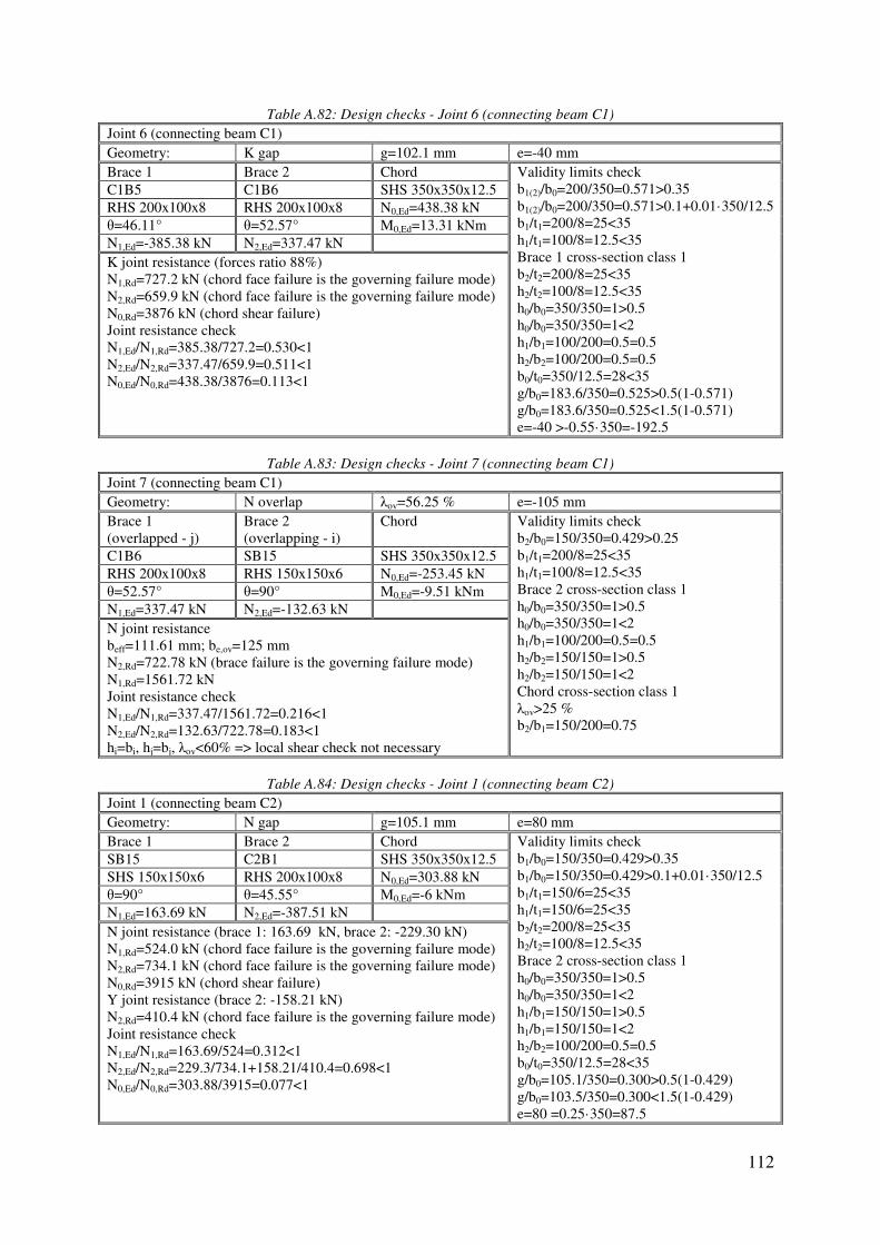
112
Table A.82: Design checks - Joint 6 (connecting beam C1)
Joint 6 (connecting beam C1) Geometry: K gap g=102.1 mm e=-40 mm Brace 1 Brace 2 Chord Validity limits check
b1(2)/b0=200/350=0.571>0.35 b1(2)/b0=200/350=0.571>0.1+0.01·350/12.5 b1/t1=200/8=25<35 h1/t1=100/8=12.5<35 Brace 1 cross-section class 1 b2/t2=200/8=25<35 h2/t2=100/8=12.5<35 h0/b0=350/350=1>0.5 h0/b0=350/350=1<2 h1/b1=100/200=0.5=0.5 h2/b2=100/200=0.5=0.5 b0/t0=350/12.5=28<35 g/b0=183.6/350=0.525>0.5(1-0.571) g/b0=183.6/350=0.525<1.5(1-0.571) e=-40 >-0.55·350=-192.5
C1B5 C1B6 SHS 350x350x12.5
RHS 200x100x8 RHS 200x100x8 N0,Ed=438.38 kN θ=46.11° θ=52.57° M0,Ed=13.31 kNm N1,Ed=-385.38 kN N2,Ed=337.47 kN K joint resistance (forces ratio 88%) N1,Rd=727.2 kN (chord face failure is the governing failure mode) N2,Rd=659.9 kN (chord face failure is the governing failure mode) N0,Rd=3876 kN (chord shear failure) Joint resistance check N1,Ed/N1,Rd=385.38/727.2=0.530<1 N2,Ed/N2,Rd=337.47/659.9=0.511<1 N0,Ed/N0,Rd=438.38/3876=0.113<1
Table A.83: Design checks - Joint 7 (connecting beam C1)
Joint 7 (connecting beam C1) Geometry: N overlap λov=56.25 % e=-105 mm Brace 1 (overlapped - j)
Brace 2 (overlapping - i)
Chord Validity limits check b2/b0=150/350=0.429>0.25 b1/t1=200/8=25<35 h1/t1=100/8=12.5<35 Brace 2 cross-section class 1 h0/b0=350/350=1>0.5 h0/b0=350/350=1<2 h1/b1=100/200=0.5=0.5 h2/b2=150/150=1>0.5 h2/b2=150/150=1<2 Chord cross-section class 1 λov>25 % b2/b1=150/200=0.75
C1B6 SB15 SHS 350x350x12.5
RHS 200x100x8 RHS 150x150x6 N0,Ed=-253.45 kN θ=52.57° θ=90° M0,Ed=-9.51 kNm N1,Ed=337.47 kN N2,Ed=-132.63 kN N joint resistance beff=111.61 mm; be,ov=125 mm N2,Rd=722.78 kN (brace failure is the governing failure mode) N1,Rd=1561.72 kN Joint resistance check N1,Ed/N1,Rd=337.47/1561.72=0.216<1 N2,Ed/N2,Rd=132.63/722.78=0.183<1 hi=bi, hj=bj, λov<60% => local shear check not necessary
Table A.84: Design checks - Joint 1 (connecting beam C2)
Joint 1 (connecting beam C2) Geometry: N gap g=105.1 mm e=80 mm Brace 1 Brace 2 Chord Validity limits check
b1/b0=150/350=0.429>0.35 b1/b0=150/350=0.429>0.1+0.01·350/12.5 b1/t1=150/6=25<35 h1/t1=150/6=25<35 b2/t2=200/8=25<35 h2/t2=100/8=12.5<35 Brace 2 cross-section class 1 h0/b0=350/350=1>0.5 h0/b0=350/350=1<2 h1/b1=150/150=1>0.5 h1/b1=150/150=1<2 h2/b2=100/200=0.5=0.5 b0/t0=350/12.5=28<35 g/b0=105.1/350=0.300>0.5(1-0.429) g/b0=103.5/350=0.300<1.5(1-0.429) e=80 =0.25·350=87.5
SB15 C2B1 SHS 350x350x12.5
SHS 150x150x6 RHS 200x100x8 N0,Ed=303.88 kN θ=90° θ=45.55° M0,Ed=-6 kNm N1,Ed=163.69 kN N2,Ed=-387.51 kN N joint resistance (brace 1: 163.69 kN, brace 2: -229.30 kN) N1,Rd=524.0 kN (chord face failure is the governing failure mode) N2,Rd=734.1 kN (chord face failure is the governing failure mode) N0,Rd=3915 kN (chord shear failure) Y joint resistance (brace 2: -158.21 kN) N2,Rd=410.4 kN (chord face failure is the governing failure mode) Joint resistance check N1,Ed/N1,Rd=163.69/524=0.312<1 N2,Ed/N2,Rd=229.3/734.1+158.21/410.4=0.698<1 N0,Ed/N0,Rd=303.88/3915=0.077<1
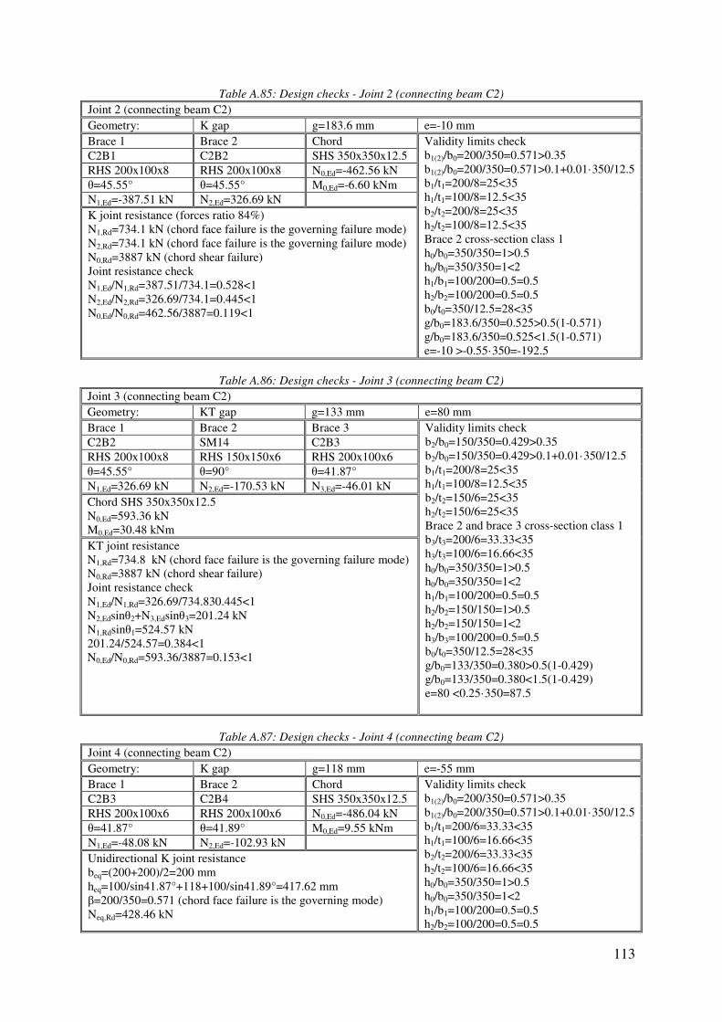
113
Table A.85: Design checks - Joint 2 (connecting beam C2)
Joint 2 (connecting beam C2) Geometry: K gap g=183.6 mm e=-10 mm Brace 1 Brace 2 Chord Validity limits check
b1(2)/b0=200/350=0.571>0.35 b1(2)/b0=200/350=0.571>0.1+0.01·350/12.5 b1/t1=200/8=25<35 h1/t1=100/8=12.5<35 b2/t2=200/8=25<35 h2/t2=100/8=12.5<35 Brace 2 cross-section class 1 h0/b0=350/350=1>0.5 h0/b0=350/350=1<2 h1/b1=100/200=0.5=0.5 h2/b2=100/200=0.5=0.5 b0/t0=350/12.5=28<35 g/b0=183.6/350=0.525>0.5(1-0.571) g/b0=183.6/350=0.525<1.5(1-0.571) e=-10 >-0.55·350=-192.5
C2B1 C2B2 SHS 350x350x12.5
RHS 200x100x8 RHS 200x100x8 N0,Ed=-462.56 kN θ=45.55° θ=45.55° M0,Ed=-6.60 kNm N1,Ed=-387.51 kN N2,Ed=326.69 kN K joint resistance (forces ratio 84%) N1,Rd=734.1 kN (chord face failure is the governing failure mode) N2,Rd=734.1 kN (chord face failure is the governing failure mode) N0,Rd=3887 kN (chord shear failure) Joint resistance check N1,Ed/N1,Rd=387.51/734.1=0.528<1 N2,Ed/N2,Rd=326.69/734.1=0.445<1 N0,Ed/N0,Rd=462.56/3887=0.119<1
Table A.86: Design checks - Joint 3 (connecting beam C2)
Joint 3 (connecting beam C2) Geometry: KT gap g=133 mm e=80 mm Brace 1 Brace 2 Brace 3 Validity limits check
b2/b0=150/350=0.429>0.35 b2/b0=150/350=0.429>0.1+0.01·350/12.5 b1/t1=200/8=25<35 h1/t1=100/8=12.5<35 b2/t2=150/6=25<35 h2/t2=150/6=25<35 Brace 2 and brace 3 cross-section class 1 b3/t3=200/6=33.33<35 h3/t3=100/6=16.66<35 h0/b0=350/350=1>0.5 h0/b0=350/350=1<2 h1/b1=100/200=0.5=0.5 h2/b2=150/150=1>0.5 h2/b2=150/150=1<2 h3/b3=100/200=0.5=0.5 b0/t0=350/12.5=28<35 g/b0=133/350=0.380>0.5(1-0.429) g/b0=133/350=0.380<1.5(1-0.429) e=80 <0.25·350=87.5
C2B2 SM14 C2B3
RHS 200x100x8 RHS 150x150x6 RHS 200x100x6 θ=45.55° θ=90° θ=41.87° N1,Ed=326.69 kN N2,Ed=-170.53 kN N3,Ed=-46.01 kN Chord SHS 350x350x12.5 N0,Ed=593.36 kN M0,Ed=30.48 kNm KT joint resistance N1,Rd=734.8 kN (chord face failure is the governing failure mode) N0,Rd=3887 kN (chord shear failure) Joint resistance check N1,Ed/N1,Rd=326.69/734.830.445<1 N2,Edsinθ2+N3,Edsinθ3=201.24 kN N1,Rdsinθ1=524.57 kN 201.24/524.57=0.384<1 N0,Ed/N0,Rd=593.36/3887=0.153<1
Table A.87: Design checks - Joint 4 (connecting beam C2)
Joint 4 (connecting beam C2) Geometry: K gap g=118 mm e=-55 mm Brace 1 Brace 2 Chord Validity limits check
b1(2)/b0=200/350=0.571>0.35 b1(2)/b0=200/350=0.571>0.1+0.01·350/12.5 b1/t1=200/6=33.33<35 h1/t1=100/6=16.66<35 b2/t2=200/6=33.33<35 h2/t2=100/6=16.66<35 h0/b0=350/350=1>0.5 h0/b0=350/350=1<2 h1/b1=100/200=0.5=0.5 h2/b2=100/200=0.5=0.5
C2B3 C2B4 SHS 350x350x12.5
RHS 200x100x6 RHS 200x100x6 N0,Ed=-486.04 kN θ=41.87° θ=41.89° M0,Ed=9.55 kNm N1,Ed=-48.08 kN N2,Ed=-102.93 kN Unidirectional K joint resistance beq=(200+200)/2=200 mm heq=100/sin41.87°+118+100/sin41.89°=417.62 mm β=200/350=0.571 (chord face failure is the governing mode) Neq,Rd=428.46 kN

114
N1,Rd=199.91 kN N2,Rd=441.86 kN Joint resistance check N1,Ed/N1,Rd=48.08/199.91=0.241<1 N2,Ed/N2,Rd=102.93/441.86=0.233<1
b0/t0=350/12.5=28<35 g/b0=118/350=0.337>0.5(1-0.571) g/b0=118/350=0.337<1.5(1-0.571) e=-55 >-0.55·350=-192.5
Table A.88: Design checks - Joint 5 (connecting beam C2)
Joint 5 (connecting beam C2) Geometry: KT gap g=100.9 mm e=80 mm Brace 1 Brace 2 Brace 3 Validity limits check
b2/b0=150/350=0.429>0.35 b2/b0=150/350=0.429>0.1+0.01·350/12.5 b1/t1=200/6=33.33<35 h1/t1=100/6=16.66<35 b2/t2=150/6=25<35 h2/t2=150/6=25<35 Brace 1 and brace 2 cross-section class 1 b3/t3=200/8=25<35 h3/t3=100/8=12.5<35 h0/b0=350/350=1>0.5 h0/b0=350/350=1<2 h1/b1=100/200=0.5=0.5 h2/b2=150/150=1>0.5 h2/b2=150/150=1<2 h3/b3=100/200=0.5=0.5 b0/t0=350/12.5=28<35 g/b0=100.9/350=0.288>0.5(1-0.429) g/b0=100.9/350=0.288<1.5(1-0.429) e=80 <0.25·350=87.5
C2B4 SM14 C2B5
RHS 200x100x6 RHS 150x150x6 RHS 200x100x8 θ=41.89° θ=90° θ=46.11° N1,Ed=-101.55 kN N2,Ed=-175.77 kN N3,Ed=379.88 kN Chord SHS 350x350x12.5 N0,Ed=593.36 kN M0,Ed=27.65 kNm KT joint resistance N3,Rd=727.9 kN (chord face failure is the governing failure mode) N0,Rd=3887 kN (chord shear failure) Joint resistance check N3,Ed/N3,Rd=379.88/727.9=0.520<1 N1,Edsinθ1+N1,Edsinθ1=243.58 kN N3,Rdsinθ3=524.58 kN 243.58/524.58=0.464<1 N0,Ed/N0,Rd=593.36/3887=0.153<1
Table A.89: Design checks - Joint 6 (connecting beam C2)
Joint 6 (connecting beam C2) Geometry: K gap g=102.1 mm e=-40 mm Brace 1 Brace 2 Chord Validity limits check
b1(2)/b0=200/350=0.571>0.35 b1(2)/b0=200/350=0.571>0.1+0.01·350/12.5 b1/t1=200/8=25<35 h1/t1=100/8=12.5<35 b2/t2=200/8=25<35 h2/t2=100/8=12.5<35 Brace 2 cross-section class 1 h0/b0=350/350=1>0.5 h0/b0=350/350=1<2 h1/b1=100/200=0.5=0.5 h2/b2=100/200=0.5=0.5 b0/t0=350/12.5=28<35 g/b0=183.6/350=0.525>0.5(1-0.571) g/b0=183.6/350=0.525<1.5(1-0.571) e=-40 >-0.55·350=-192.5
C2B5 C2B6 SHS 350x350x12.5
RHS 200x100x8 RHS 200x100x8 N0,Ed=-422.71 kN θ=46.11° θ=52.57° M0,Ed=-4.33 kNm N1,Ed=379.88 kN N2,Ed=-372.76 kN K joint resistance (forces ratio 98%) N1,Rd=727.2 kN (chord face failure is the governing failure mode) N2,Rd=659.9 kN (chord face failure is the governing failure mode) N0,Rd=3876 kN (chord shear failure) Joint resistance check N1,Ed/N1,Rd=379.88/727.2=0.522<1 N2,Ed/N2,Rd=372.76/659.9=0.565<1 N0,Ed/N0,Rd=422.71/3876=0.109<1
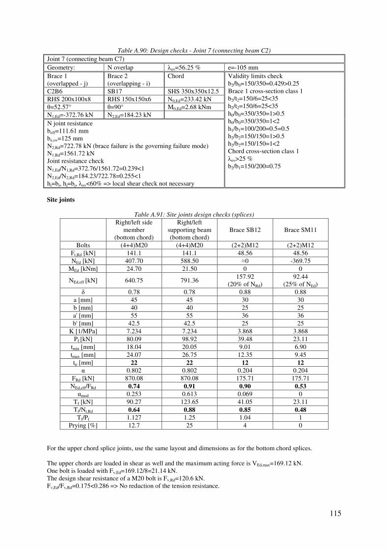
115
Table A.90: Design checks - Joint 7 (connecting beam C2)
Joint 7 (connecting beam C7) Geometry: N overlap λov=56.25 % e=-105 mm Brace 1 (overlapped - j)
Brace 2 (overlapping - i)
Chord Validity limits check b2/b0=150/350=0.429>0.25 Brace 1 cross-section class 1 b2/t2=150/6=25<35 h2/t2=150/6=25<35 h0/b0=350/350=1>0.5 h0/b0=350/350=1<2 h1/b1=100/200=0.5=0.5 h2/b2=150/150=1>0.5 h2/b2=150/150=1<2 Chord cross-section class 1 λov>25 % b2/b1=150/200=0.75
C2B6 SB17 SHS 350x350x12.5
RHS 200x100x8 RHS 150x150x6 N0,Ed=233.42 kN θ=52.57° θ=90° M0,Ed=2.68 kNm N1,Ed=-372.76 kN N2,Ed=184.23 kN N joint resistance beff=111.61 mm be,ov=125 mm N2,Rd=722.78 kN (brace failure is the governing failure mode) N1,Rd=1561.72 kN Joint resistance check N1,Ed/N1,Rd=372.76/1561.72=0.239<1 N2,Ed/N2,Rd=184.23/722.78=0.255<1 hi=bi, hj=bj, λov<60% => local shear check not necessary Site joints
Table A.91: Site joints design checks (splices)
Right/left side
member (bottom chord)
Right/left supporting beam (bottom chord)
Brace SB12 Brace SM11
Bolts (4+4)M20 (4+4)M20 (2+2)M12 (2+2)M12 Ft,Rd [kN] 141.1 141.1 48.56 48.56 NEd [kN] 407.70 588.50 ≈0 -369.75
MEd [kNm] 24.70 21.50 0 0
NEd,eff [kN] 640.75 791.36 157.92
(20% of NRd) 92.44
(25% of NEd) δ 0.78 0.78 0.88 0.88
a [mm] 45 45 30 30 b [mm] 40 40 25 25 a' [mm] 55 55 36 36 b' [mm] 42.5 42.5 25 25
K [1/MPa] 7.234 7.234 3.868 3.868 Pf [kN] 80.09 98.92 39.48 23.11
tmin [mm] 18.04 20.05 9.01 6.90 tmax [mm] 24.07 26.75 12.35 9.45 tp [mm] 22 22 12 12
α 0.802 0.802 0.204 0.204 FRd [kN] 870.08 870.08 175.71 175.71 NEd,eff/FRd 0.74 0.91 0.90 0.53
αmod 0.253 0.613 0.069 0 Tf [kN] 90.27 123.65 41.05 23.11 Tf/Nt,Rd 0.64 0.88 0.85 0.48
Tf/Pf 1.127 1.25 1.04 1 Prying [%] 12.7 25 4 0
For the upper chord splice joints, use the same layout and dimensions as for the bottom chord splices. The upper chords are loaded in shear as well and the maximum acting force is VEd,max=169.12 kN. One bolt is loaded with Fv,Ed=169.12/8=21.14 kN. The design shear resistance of a M20 bolt is Fv,Rd=120.6 kN. Fv,Ed/Fv,Rd=0.175<0.286 => No reduction of the tension resistance.

116
Weight of the structure
Table A.92: Weight (right/left side member-braces)
Member Cross-section Length [mm]
Unit weight [kg/m]
Total weight
[kg] SM1 RHS 200x100x6 1150 26.4 30.36 SM2 RHS 200x100x6 1568 26.4 41.40 SM3 RHS 200x100x8 1642 33.9 55.66 SM4 SHS 150x150x6 1150 26.4 30.36 SM4 RHS 200x100x8 1446 33.9 49.02 SM6 RHS 200x100x6 1426 26.4 37.65 SM7 RHS 200x100x6 1426 26.4 37.65 SM8 RHS 200x100x6 1426 26.4 37.65 SM9 RHS 200x100x6 1426 26.4 37.65
SM10 RHS 200x100x6 1415 26.4 37.36 SM11 SHS 200x200x10 1467 57 83.62 SM12 SHS 150x150x6 1150 26.4 30.36 SM13 SHS 200x200x10 1515 57 86.36 SM14 SHS 150x150x6 1150 26.4 30.36
Σ 625.43 2·Σ 1250.87
Table A.93: Weight (right/left supporting beam-braces)
Member Cross-section Length [mm]
Unit weight [kg/m]
Total weight
[kg] SB1 RHS 200x100x6 1150 26.4 30.36 SB2 RHS 200x100x6 1580 26.4 41.71 SB3 SHS 150x150x6 1150 26.4 30.36 SB4 RHS 200x100x6 1659 26.4 43.80 SB5 SHS 150x150x6 1150 26.4 30.36 SB6 RHS 200x100x6 1447 26.4 38.20 SB7 RHS 160x80x5 1414 17.5 24.75 SB8 RHS 160x80x5 1414 17.5 24.75 SB9 RHS 160x80x5 1414 17.5 24.75
SB10 RHS 160x80x5 1414 17.5 24.75 SB11 RHS 160x80x5 1434 17.5 25.10 SB12 RHS 200x100x6 1434 26.4 37.86 SB13 SHS 150x150x6 1150 26.4 30.36 SB14 SHS 200x200x10 1529 57 87.15 SB15 SHS 150x150x6 1150 26.4 30.36 SB16 SHS 200x200x10 1695 57 96.62 SB17 SHS 150x150x6 1150 26.4 30.36
Σ 651.57
2·Σ 1303.14
Table A.94: Weight (connecting beam C1-braces)
Member Cross-section Length [mm]
Unit weight [kg/m]
Total weight
[kg] C1B1 RHS 200x100x8 1709 33.9 57.94 C1B2 RHS 200x100x8 1709 33.9 57.94 C1B3 RHS 200x100x6 1835 26.4 48.44 C1B4 RHS 200x100x6 1835 26.4 48.44 C1B5 RHS 200x100x8 1692 33.9 57.36 C1B6 RHS 200x100x8 1525 33.9 51.70
Σ 321.81

117
Table A.95: Weight (connecting beam C2-braces)
Member Cross-section Length [mm]
Unit weight [kg/m]
Total weight
[kg] C2B1 RHS 200x100x8 1709 33.9 57.94 C2B2 RHS 200x100x8 1709 33.9 57.94 C2B3 RHS 200x100x6 1835 26.4 48.44 C2B4 RHS 200x100x6 1835 26.4 48.44 C2B5 RHS 200x100x8 1692 33.9 57.36 C2B6 RHS 200x100x8 1525 33.9 51.70
Σ 321.81
Table A.96: Weight (chords)
Member Cross-section Length [mm]
Unit weight [kg/m]
Quantity Total
weight [kg]
Right side member SHS 350x350x12.5 9933 127 2 2522.98 Left side member SHS 350x350x12.5 9933 127 2 2522.98
Right supporting beam SHS 350x350x12.5 12000 127 2 3048.00 Left supporting beam SHS 350x350x12.5 12000 127 2 3048.00
Connecting beam SHS 350x350x12.5 8650 127 4 4394.20
Σ 15536.16
Table A.97: Weight (brackets)
Member Cross-section Length [mm]
Unit weight [kg/m]
Quantity Total
weight [kg]
Vertical HEB 360 4360 142 4 2476.48 Diagonal-left HEB 360 3134 142 2 890.06
Diagonal-right HEB 360 3518 142 2 999.11 Horizontal1-left HEA 800 3020 224 2 1352.96
Horizontal1-right HEA 800 3580 224 2 1603.84 Horizontal2-left RHS 200x100x6 1645 26.4 2 86.86
Horizontal2-right RHS 200x100x6 2208 26.4 2 116.58 Longitudinal IPE 550 2535 106 2 537.42
Σ 8063.31

118
B. Annex B
List of tables
Table B.1: Material properties and partial safety factors ............................................................................ 120 Table B.2: Designation - brace members .................................................................................................... 120 Table B.3: Tension forces [kN] - right/left side member (braces) ............................................................... 120 Table B.4: Design checks (tension) - right/left side member (braces) ........................................................ 121 Table B.5: Tension forces [kN] - right/left supporting beam (braces) ........................................................ 121 Table B.6: Design checks (tension) - right/left supporting beam (braces) .................................................. 121 Table B.7: Tension forces [kN] - connecting beam (braces) ....................................................................... 121 Table B.8: Design checks (tension) - connecting beam (braces) ................................................................. 122 Table B.9: Cross-section classification for the braces loaded in compression ............................................ 122 Table B.10: Compression forces [kN] - right/left side member (braces) .................................................... 122 Table B.11: Design checks (compression + stability) - right/left side member (braces) ............................. 122 Table B.12: Compression forces [kN] - right/left supporting beam (braces) .............................................. 123 Table B.13: Design checks (compression + stability) - right/left supporting beam (braces) ....................... 123 Table B.14: Compression forces [kN] - connecting beam (braces) ............................................................. 123 Table B.15: Design checks (compression + stability) - connecting beam (braces) ..................................... 123 Table B.16: Cross-section classification (bottom chords) ........................................................................... 124 Table B.17: Chords - design resistances ...................................................................................................... 124 Table B.18: Internal forces and design checks (bending and
axial forces) - right/left side member (bottom ch.) ................................................................. 124 Table B.19: Internal forces and design checks (shear) - right/left side member (bottom chord)................. 125 Table B.20: Internal forces and design checks (bending and
axial forces) - right/left suppor. beam (bottom ch.) ................................................................ 125 Table B.21: Internal forces and design checks (shear) - right/left supporting beam (bottom chord) .......... 125 Table B.22: Internal forces and design checks (bending and
axial forces) - connecting beam (bottom chord) ..................................................................... 126 Table B.23: Internal forces and design checks (shear) - connecting beam (bottom chord) ......................... 127 Table B.24: Cross-section classification (upper chords) ............................................................................. 127 Table B.25: Chords - design resistances ...................................................................................................... 127 Table B.26: Internal forces and design checks (bending and
axial forces) - right/left side member (upper ch.) ................................................................... 127 Table B.27: Internal forces and design checks (shear) - right/left side member (upper chord) ................... 128 Table B.28: Stability checks - right/left side member (upper chord) .......................................................... 128 Table B.29: Internal forces and design checks (bending and
axial forces) - right/left suppor. beam (upper ch.) .................................................................. 128 Table B.30: Internal forces and design checks (shear) - right/left supporting beam (upper chord)............. 129 Table B.31: Stability checks - right/left supporting beam (upper chord) .................................................... 129 Table B.32: Internal forces and design checks (bending and
axial forces) - connecting beam (upper chord) ....................................................................... 129 Table B.33: Internal forces and design checks (shear) - connecting beam (upper chord) ........................... 130 Table B.34: Stability checks - connecting beam (upper chord) ................................................................... 130 Table B.35: Cross-section classification (bracket-diagonal) ....................................................................... 130 Table B.36: Compression forces [kN] - bracket (diagonal) ........................................................................ 131 Table B.37: Bracket (diagonal) - design resistances ................................................................................... 131 Table B.38: Design checks (compression + stability) - bracket (diagonal) ................................................. 131 Table B.39: Cross-section classification (bracket-vertical) ......................................................................... 131 Table B.40: Bracket (vertical) - design resistances ..................................................................................... 131 Table B.41: Internal forces and design checks (bending and axial forces) - bracket (vertical) ................... 131 Table B.42: Stability checks - bracket (vertical) ......................................................................................... 132 Table B.43: Cross-section classification (bracket-horizontal) ..................................................................... 132 Table B.44: Bracket (horizontal) - design resistances ................................................................................. 132 Table B.45: Internal forces and design checks (bending and axial forces) - bracket (horizontal) ............... 132 Table B.46: Stability checks - bracket (horizontal) ..................................................................................... 133 Table B.47: Designation - joints .................................................................................................................. 133 Table B.48: Design checks - Joint 1 (right/left side member) ..................................................................... 134 Table B.49: Design checks - Joint 2 (right/left side member) ..................................................................... 134

119
Table B.50: Design checks - Joint 3 (right/left side member) ..................................................................... 134 Table B.51: Design checks - Joint 4 (right/left side member) ..................................................................... 135 Table B.52: Design checks - Joint 5 (right/left side member) ..................................................................... 135 Table B.53: Design checks - Joint 6 (right/left side member) ..................................................................... 135 Table B.54: Design checks - Joint 7 (right/left side member) ..................................................................... 136 Table B.55: Design checks - Joint 8 (right/left side member) ..................................................................... 136 Table B.56: Design checks - Joint 9 (right/left side member) ..................................................................... 136 Table B.57: Design checks - Joint 10 (right/left side member) ................................................................... 137 Table B.58: Design checks - Joint 11 (right/left side member) ................................................................... 137 Table B.59: Design checks - Joint 12 (right/left side member) ................................................................... 137 Table B.60: Design checks - Joint 13 (right/left side member) ................................................................... 138 Table B.61: Design checks - Joint 1 (right/left supporting beam) ............................................................... 138 Table B.62: Design checks - Joint 2 (right/left supporting beam) ............................................................... 138 Table B.63: Design checks - Joint 3 (right/left supporting beam) ............................................................... 139 Table B.64: Design checks - Joint 4 (right/left supporting beam) ............................................................... 139 Table B.65: Design checks - Joint 5 (right/left supporting beam) ............................................................... 139 Table B.66: Design checks - Joint 6 (right/left supporting beam) ............................................................... 140 Table B.67: Design checks - Joint 7 (right/left supporting beam) ............................................................... 140 Table B.68: Design checks - Joint 8 (right/left supporting beam) ............................................................... 140 Table B.69: Design checks - Joint 9 (right/left supporting beam) ............................................................... 141 Table B.70: Design checks - Joint 10 (right/left supporting beam) ............................................................. 141 Table B.71: Design checks - Joint 11 (right/left supporting beam) ............................................................. 141 Table B.72: Design checks - Joint 12 (right/left supporting beam) ............................................................. 142 Table B.73: Design checks - Joint 13 (right/left supporting beam) ............................................................. 142 Table B.74: Design checks - Joint 14 (right/left supporting beam) ............................................................. 142 Table B.75: Design checks - Joint 15 (right/left supporting beam) ............................................................. 143 Table B.76: Design checks - Joint 16 (right/left supporting beam) ............................................................. 143 Table B.77: Design checks - Joint 1 (connecting beam C1) ........................................................................ 143 Table B.78: Design checks - Joint 2 (connecting beam C1) ........................................................................ 144 Table B.79: Design checks - Joint 3 (connecting beam C1) ........................................................................ 144 Table B.80: Design checks - Joint 4 (connecting beam C1) ........................................................................ 144 Table B.81: Design checks - Joint 5 (connecting beam C1) ........................................................................ 145 Table B.82: Design checks - Joint 6 (connecting beam C1) ........................................................................ 145 Table B.83: Design checks - Joint 7 (connecting beam C1) ........................................................................ 145 Table B.84: Design checks - Joint 1 (connecting beam C2) ........................................................................ 146 Table B.85: Design checks - Joint 2 (connecting beam C2) ........................................................................ 146 Table B.86: Design checks - Joint 3 (connecting beam C2) ........................................................................ 146 Table B.87: Design checks - Joint 4 (connecting beam C2) ........................................................................ 147 Table B.88: Design checks - Joint 5 (connecting beam C2) ........................................................................ 147 Table B.89: Design checks - Joint 6 (connecting beam C2) ........................................................................ 147 Table B.90: Design checks - Joint 7 (connecting beam C2) ........................................................................ 148 Table B.91: Site joints design checks (splices) ........................................................................................... 148 Table B.92: Weight (right/left side member-braces) ................................................................................... 149 Table B.93: Weight (right/left supporting beam-braces) ............................................................................. 149 Table B.94: Weight (connecting beam C1-braces)...................................................................................... 149 Table B.95: Weight (connecting beam C2-braces)...................................................................................... 150 Table B.96: Weight (chords) ....................................................................................................................... 150 Table B.97: Weight (brackets) .................................................................................................................... 150
Note: Drawings are provided at the end of the report.

Table B
Right/left side
member
Right/left supporting
beam
Connecting beam
Braces loaded in tension
Table B.3: Tension forces [kN]
Right side member
Member X1,ULS X2,ULS SM2 14.81 64.91
SM5 45.91 252.85
SM7 14.22 75.76
SM10 31.62 168.31
SM12 6.52 12.39
SM13 42.41 325.39
B.1: Material properties and partial safety factors
Coeff. Value fy [N/mm2] 235 fu [N/mm2] 360
ε 1 γM0 1 γM1 1 γM2 1.25
Table B.2: Designation - brace members
: Tension forces [kN] - right/left side member (braces)
Right side member Left side member
X3,ULS X4,ULS X1,ULS X2,ULS X3,ULS 69.13 60.78 14.35 59.52 64.33
256.54 249.45 47.05 255.62 259.57
80.64 70.97 16.18 83.65 88.84
167.02 171.8 29.90 162.32 159.71
10.68 14.15 4.85 8.27 6.50
322.21 328.84 45.80 335.17 332.00
120
X4,ULS NEd,max 54.79 69.13
251.97 259.57
78.56 88.84
165.11 171.80
10.08 14.15
338.62 338.62

121
Table B.4: Design checks (tension) - right/left side member (braces)
Mem. Section Bolts
Φ No. bolts
A [mm2]
Anet [mm2]
Npl,Rd
[kN] P1
[mm] d0
[mm] β
Nu,Rd
[kN] NRd,1
[kN] NRd
[kN] NEd/NRd
MB2 L100x12 12 3 2270 2156.9 533.45 70 13 0.7 559.07 533.45 533.5 0.130
MB5 2L100x12 16 3 2270 2068.9 533.45 70 18 0.611 536.27 533.45 1066.9 0.243
MB7 2L90x10 12 2 1710 1596.9 401.85 70 13 0.7 413.92 401.85 803.7 0.110
MB10 2L90x10 12 2 1710 1596.9 401.85 70 13 0.7 413.92 401.85 803.7 0.214
MB12 2L90x10 12 2 1710 1596.9 401.85 70 13 0.7 413.92 401.85 803.7 0.018
MB13 2L130x12 16 3 3000 2798.9 705.00 70 18 0.611 725.48 705.00 1410.0 0.240
Table B.5: Tension forces [kN] - right/left supporting beam (braces)
Right supporting beam Left supporting beam
Member X1,ULS X2,ULS X3,ULS X4,ULS X1,ULS X2,ULS X3,ULS X4,ULS NEd,max SB1 24.21 98.52 100.96 96.22 22.49 93.87 96.47 91.41 100.96
SB5 13.99 66.52 64.29 68.85 14.29 71.04 68.52 73.66 73.66
SB6 55.50 190.61 194.37 187.19 56.31 202.14 206.23 198.40 206.23
SB8 26.41 87.62 90.07 85.32 27.07 94.95 97.54 92.52 97.54
SB10 16.96 75.57 77.99 73.25 17.58 82.71 85.23 80.30 85.23
SB14 64.23 251.80 246.02 258.00 66.54 274.47 267.90 281.45 281.45
SB15 43.86 159.38 157.64 161.40 48.54 179.51 177.58 181.75 181.75
Table B.6: Design checks (tension) - right/left supporting beam (braces)
Mem. Section Bolts
Φ No. bolts
A [mm2]
Anet [mm2]
Npl,Rd
[kN] P1
[mm] d0
[mm] β
Nu,Rd
[kN] NRd,1
[kN] NRd
[kN] NEd/NRd
SB1 2L90x10 12 2 1710 1596.9 401.85 70 13 0.7 413.92 401.85 803.7 0.126
SB5 2L90x10 12 2 1710 1596.9 401.85 70 13 0.7 413.92 401.85 803.7 0.092
SB6 2L90x10 12 3 1710 1596.9 401.85 70 13 0.7 413.92 401.85 803.7 0.257
SB8 L100x12 16 2 2270 2068.9 533.45 70 18 0.566 536.27 533.45 533.45 0.183
SB10 L100x12 16 2 2270 2068.9 533.45 70 18 0.566 536.27 533.45 533.45 0.160
SB14 2L130x12 12 3 3000 2886.9 705.00 70 13 0.7 748.29 705.00 1410.0 0.200
SB15 2L90x10 12 2 1710 1596.9 401.85 70 13 0.7 413.92 401.85 803.7 0.226
Table B.7: Tension forces [kN] - connecting beam (braces)
Member X1,ULS X2,ULS X3,ULS X4,ULS NEd,max
C1B1 70.51 360.56 357.09 364.47 364.47
C1B3 11.54 37.94 39.30 36.66 39.30
C1B4 22.25 88.25 89.03 87.62 89.03
C1B6 67.10 355.51 351.50 359.93 359.93
C2B2 78.30 323.05 318.96 327.63 327.63
C2B5 83.92 342.68 338.80 347.10 347.10

122
Table B.8: Design checks (tension) - connecting beam (braces)
Mem. Section Bolts
Φ No. bolts
A [mm2]
Anet [mm2]
Npl,Rd
[kN] P1
[mm] d0
[mm] β
Nu,Rd
[kN] NRd,1
[kN] NRd
[kN] NEd/NRd
C1B1 2L100x12 16 4 2270 2068.9 533.45 70 18 0.611 536.27 533.45 1066.9 0.342
C1B3 2L90x10 12 2 1710 1596.9 401.85 70 13 0.7 413.92 401.85 803.7 0.049
C1B4 2L90x10 12 2 1710 1596.9 401.85 70 13 0.7 413.92 401.85 803.7 0.111
C1B6 2L100x12 16 4 2270 2068.9 533.45 70 18 0.611 536.27 533.45 1066.9 0.337
C2B2 2L100x12 16 4 2270 2068.9 533.45 70 18 0.611 536.27 533.45 1066.9 0.307
C2B5 2L100x12 16 4 2270 2068.9 533.45 70 18 0.611 536.27 533.45 1066.9 0.325 Braces loaded in compression
Table B.9: Cross-section classification for the braces loaded in compression
Cross-section h
[mm] t
[mm] h/t
b+h
2t Class
L 90x10 90 10 9 9 3 L 100x12 100 12 8.33 8.33 3 L 130x12 130 12 10.83 10.83 3
Limiting values (S235): Class 3: h/t<15, (b+h)/(2t)<11.5
Table B.10: Compression forces [kN] - right/left side member (braces)
Right side member Left side member Member X1,ULS X2,ULS X3,ULS X4,ULS X1,ULS X2,ULS X3,ULS X4,ULS NEd,max
SM1 14.06 142.18 145.82 138.65 13.52 137.46 141.56 133.45 145.82
SM3 31.34 201.45 208.03 195.08 31.37 197.88 205.28 190.68 208.03
SM4 24.86 190.58 190.04 191.28 25.83 196.47 195.45 197.65 197.65
SM6 44.73 346.11 351.34 341.16 46.70 353.82 359.47 348.53 359.47
SM8 tension 39.20 44.23 34.09 tension 46.69 52.06 41.24 52.06
SM9 22.78 156.56 154.62 158.63 20.82 148.89 146.60 151.31 158.63
SM11 40.03 356.44 351.41 361.72 39.66 353.12 347.89 358.61 361.72
SM14 29.48 167.21 164.2 170.41 30.50 168.02 165.17 171.07 171.07
Table B.11: Design checks (compression + stability) - right/left side member (braces)
Mem. Section A
[mm2] Npl,Rd
[kN] Lcr
[mm] iy=iz
[mm] iv
[mm] λ�eff,y λ�eff,v Φ χ
Nb,Rd,1
[kN] Nb,Rd
[kN] NEd/ Nb,Rd
SM1 2L90x10 1710 401.9 1500 27.2 17.5 0.911 0.989 1.123 0.604 242.7 485.5 0.30
SM3 2L100x12 2270 533.5 1963.8 30.2 19.4 0.985 1.105 1.264 0.532 284.1 568.1 0.37
SM4 2L90x10 1710 401.9 1500 27.2 17.5 0.911 0.989 1.123 0.604 242.7 485.5 0.41
SM6 2L100x12 2270 533.5 1777.7 30.2 19.4 0.939 1.033 1.175 0.576 307.4 614.7 0.59
SM8 2L90x10 1710 401.9 1777.7 27.2 17.5 0.987 1.107 1.267 0.531 213.3 426.7 0.12
SM9 2L90x10 1710 401.9 1777.7 27.2 17.5 0.987 1.107 1.267 0.531 213.3 426.7 0.37
SM11 2L130x12 3000 705.0 1777.7 39.7 25.4 0.834 0.872 0.994 0.679 478.9 957.8 0.38
SM14 2L90x10* 3420 803.7 1500 41.9
0.382
0.604 0.933 750.1 750.1 0.23 Lcr=Lsys α=0.34 Brace member SM14 is star-battened

123
Table B.12: Compression forces [kN] - right/left supporting beam (braces)
Right supporting beam Left supporting beam
Member X1,ULS X2,ULS X3,ULS X4,ULS X1,ULS X2,ULS X3,ULS X4,ULS NEd,max
SB2 24.78 83.32 85.64 82.17 21.93 74.20 76.40 72.14 85.64
SB3 35.50 132.63 134.63 130.86 34.67 133.30 135.38 131.44 135.38
SB4 89.16 352.50 356.32 349.25 89.95 368.14 371.66 365.20 371.66
SB7 31.49 98.46 101.19 95.94 32.07 105.63 108.44 103.02 108.44
SB9 22.12 82.67 85.11 80.37 22.80 90.14 92.70 87.73 92.70
SB11 14.34 73.59 75.82 71.45 15.16 80.95 83.28 78.71 83.28
SB12 4.99 10.54 7.60 13.52 4.32 8.64 5.38 11.94 13.52
SB13 25.42 124.1 122.99 125.37 25.11 130.20 128.80 131.76 131.76
SB16 152.25 568.15 556.90 580.38 163.03 630.90 618.13 644.70 644.70
SB17 7.97 18.63 19.28 18.03 9.09 22.68 23.44 21.98 23.44
Table B.13: Design checks (compression + stability) - right/left supporting beam (braces)
Table B.14: Compression forces [kN] - connecting beam (braces)
Member X1,ULS X2,ULS X3,ULS X4,ULS NEd,max
C1B2 61.64 341.81 336.87 347.15 347.15
C1B5 62.92 354.09 348.84 359.74 359.74
C2B1 97.11 384.33 381.57 387.71 387.71
C2B3 8.61 46.04 47.13 45.01 47.13
C2B4 23.07 99.87 100.59 99.29 100.59
C2B6 99.30 397.39 394.62 400.79 400.79
Table B.15: Design checks (compression + stability) - connecting beam (braces)
Mem. Section A
[mm2] Npl,Rd
[kN] Lcr
[mm] iy=iz
[mm] iv
[mm] λ�eff,y λ�eff,v Φ χ
Nb,Rd,1
[kN] Nb,Rd
[kN] NEd/ Nb,Rd
SB2 L100x12 2270 533.5 1963.8 30.2 19.4 0.985 1.105 1.264 0.532 284.0 284.0 0.30
SB3 2L90x10 1710 401.9 1500 27.2 17.5 0.911 0.989 1.123 0.604 242.7 485.5 0.28
SB4 2L90x10 1710 401.9 1963.8 27.2 17.5 1.038 1.187 1.372 0.485 195.1 390.2 0.95
SB7 L100x12 2270 533.5 1777.7 30.2 19.4 0.939 1.033 1.175 0.576 307.4 307.4 0.35
SB9 L100x12 2270 533.5 1777.7 30.2 19.4 0.939 1.033 1.175 0.576 307.4 307.4 0.30
SB11 L100x12 2270 533.5 1777.7 30.2 19.4 0.939 1.033 1.175 0.576 307.4 307.4 0.27
SB12 L100x12 2270 533.5 1777.7 30.2 19.4 0.939 1.033 1.175 0.576 307.4 307.4 0.04
SB13 2L90x10* 3420 803.7 1500 41.9
0.382
0.604 0.933 750.1 750.1 0.18
SB16 2L130x12 3000 705.0 1996.1 39.7 25.4 0.875 0.936 1.063 0.638 449.9 899.7 0.72
SB17 2L90x10 1710 401.9 1500 27.2 17.5 0.911 0.989 1.123 0.604 242.7 485.5 0.05 Lcr=Lsys; α=0.34 Brace member SB13 is star-battened
Mem. Section A
[mm2] Npl,Rd
[kN] Lcr
[mm] iy=iz
[mm] iv
[mm] λ�eff,y λ�eff,v Φ χ
Nb,Rd,1
[kN] Nb,Rd
[kN] NEd/ Nb,Rd
C1B2 2L100x12 2270 533.5 2149.8 30.2 19.4 1.031 1.176 1.358 0.491 262.1 524.1 0.66
C1B5 2L100x12 2270 533.5 1959 30.2 19.4 0.984 1.103 1.262 0.534 284.6 569.3 0.63
C2B1 2L100x12 2270 533.5 2149.8 30.2 19.4 1.031 1.176 1.358 0.491 262.1 524.1 0.74
C2B3 2L90x10 1710 401.9 2267.2 27.2 17.5 1.121 1.316 1.555 0.419 168.5 337.0 0.14
C2B4 2L90x10 1710 401.9 2267.2 27.2 17.5 1.121 1.316 1.555 0.419 168.5 337.0 0.30
C2B6 2L100x12 2270 533.5 1959 30.2 19.4 0.984 1.103 1.262 0.534 284.6 569.3 0.70 Lcr=Lsys; α=0.34

Bottom chords
Table B
Cross-section
SHS 350x350x12.5c≈b-3t Bottom chord is classified Limiting values for the compression flange(S235):Class 1: c/t=33 Class 2: c/t=38 Class 3: c/t=42
Table B.18: Internal forces and design checks (bending and axial forces)
max. N (tension), corr. M
Comb. NEd
[kN] MEd
[kNm]
Rig
ht s
ide
mem
ber
X1,ULS 78.92 2.75
X2,ULS 533.37 31.54
X3,ULS 562.81 31.72
X4,ULS 544.76 31.45
Lef
t sid
e m
embe
r
X1,ULS 82.10 2.76
X2,ULS 559.97 31.48
X3,ULS 567.36 31.65
X4,ULS 553.12 31.33
Diagram is given for X3,ULS, left side member
B.16: Cross-section classification (bottom chords)
c
[mm] t
[mm] c/t
SHS 350x350x12.5 312.5 12.5 25
Bottom chord is classified for pure bending (safe-side assumption) Limiting values for the compression flange(S235):
Table B.17: Chords - design resistances
SHS 350x350x12.5 NRd [kN] 3807
MRd [kNm] 474.7 VRd [kN] 1187.18
: Internal forces and design checks (bending and axial forces) - right/left side member (bottom ch.)
max. N (tension), corr. M max. M, corr. N
Ed [kNm]
NEd/ NRd
MEd/ MRd
NEd/NRd+ MEd/MRd
NEd
[kN] MEd
[kNm] NEd
NRd
2.75 0.02 0.01 0.03 29.58 10.36 0.01
31.54 0.14 0.07 0.21 172.94 68.42 0.05
31.72 0.15 0.07 0.21 175.32 70.22 0.05
31.45 0.14 0.07 0.21 170.73 66.70 0.04
2.76 0.02 0.01 0.03 29.45 11.01 0.01
31.48 0.15 0.07 0.21 166.69 72.32 0.04
31.65 0.15 0.07 0.22 168.49 74.32 0.04
31.33 0.15 0.07 0.21 165.14 70.40 0.04
, left side member
124
Class
1
right/left side member (bottom ch.)
max. M, corr. N (tension)
Ed/ Rd
MEd/ MRd
NEd/NRd+ MEd/MRd
0.01 0.02 0.03
0.05 0.14 0.19
0.05 0.15 0.19
0.04 0.14 0.19
0.01 0.02 0.03
0.04 0.15 0.20
0.04 0.16 0.20
0.04 0.15 0.19

Table B.19: Internal forces and design checks (shear)
Member
Right side member Left side member
Table B.20: Internal forces and design checks (bending and axial forces)
max. N (tension), corr. M
Comb. NEd
[kN] MEd
[kNm]
Rig
ht
supp
orti
ng
beam
L
eft
X1,ULS 134.53 3.41
X2,ULS 516.23 22.08
X3,ULS 537.15 22.58
X4,ULS 496.09 21.62
Lef
t su
ppor
ting
be
am
X1,ULS 139.77 3.09
X2,ULS 561.77 23.82
X3,ULS 586.06 24.33
X4,ULS 538.51 23.33
Diagram is given for X3,ULS, left supporting beam
Table B.21: Internal forces and design checks (shear)
Member
Right supporting beamLeft supporting beam
: Internal forces and design checks (shear) - right/left side member (bottom chord)
Shear forces [kN] X1,ULS X2,ULS X3,ULS X4,ULS VEd,max 20.99 101.64 103.21 100.15 103.21 20.99 105.77 107.49 104.15 107.49
: Internal forces and design checks (bending and axial forces) - right/left suppor. beam (bottom ch.)
max. N (tension), corr. M max. M, corr. N (tension)
Ed [kNm]
NEd/ NRd
MEd/ MRd
NEd/NRd+ MEd/MRd
NEd
[kN] MEd
[kNm] NEd
NRd
3.41 0.04 0.01 0.04 45.20 30.16 0.01
22.08 0.14 0.05 0.18 188.49 116.89 0.05
22.58 0.14 0.05 0.19 194.18 118.25 0.05
21.62 0.13 0.05 0.18 183.07 115.73 0.05
3.09 0.04 0.01 0.04 47.61 29.30 0.01
23.82 0.15 0.05 0.20 205.62 117.18 0.05
24.33 0.15 0.05 0.21 212.32 118.61 0.06
23.33 0.14 0.05 0.19 199.23 115.94 0.05
, left supporting beam
: Internal forces and design checks (shear) - right/left supporting beam (bottom chord)
Shear forces [kN] X1,ULS X2,ULS X3,ULS X4,ULS VEd,max
Right supporting beam 37.14 148.66 148.66 148.90 148.90 36.37 150.36 150.02 150.92 150.92
125
right/left side member (bottom chord)
VEd/VRd
0.09 0.09
right/left suppor. beam (bottom ch.)
max. M, corr. N (tension)
Ed/ Rd
MEd/ MRd
NEd/NRd+ MEd/MRd
0.01 0.06 0.08
0.05 0.25 0.30
0.05 0.25 0.30
0.05 0.24 0.29
0.01 0.06 0.07
0.05 0.25 0.30
0.06 0.25 0.31
0.05 0.24 0.30
beam (bottom chord)
VEd/VRd
0.13 0.13
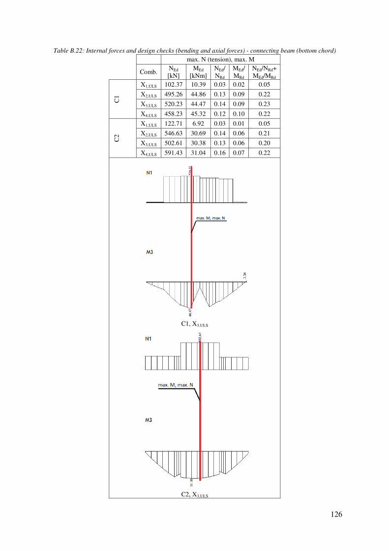
Table B.22: Internal forces and design checks (bending and axial forces)
Comb.
C1
C2
: Internal forces and design checks (bending and axial forces) - connecting beam (bottom chord)
max. N (tension), max. M
Comb. NEd
[kN] MEd
[kNm] NEd/ NRd
MEd/ MRd
NEd/NRd+ MEd/MRd
X1,ULS 102.37 10.39 0.03 0.02 0.05
X2,ULS 495.26 44.86 0.13 0.09 0.22
X3,ULS 520.23 44.47 0.14 0.09 0.23
X4,ULS 458.23 45.32 0.12 0.10 0.22
X1,ULS 122.71 6.92 0.03 0.01 0.05
X2,ULS 546.63 30.69 0.14 0.06 0.21
X3,ULS 502.61 30.38 0.13 0.06 0.20
X4,ULS 591.43 31.04 0.16 0.07 0.22
C1, X3,ULS
C2, X3,ULS
126
connecting beam (bottom chord)
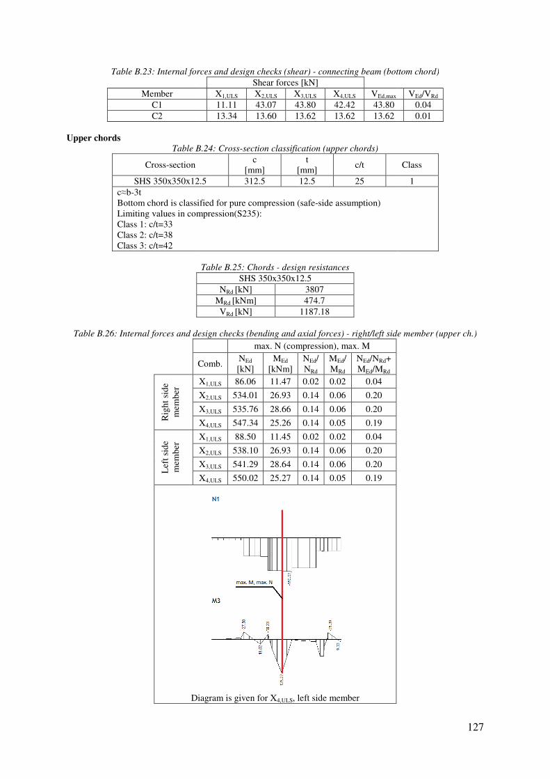
Table B.23: Internal forces and design checks (shear)
Member
C1 C2
Upper chords
Table B
Cross-section
SHS 350x350x12.5c≈b-3t Bottom chord is classified for pure compression (safeLimiting values in compression(S235):Class 1: c/t=33 Class 2: c/t=38 Class 3: c/t=42
Table B.26: Internal forces and design checks (bending and axial forces)
Comb.
Rig
ht s
ide
mem
ber
Lef
t sid
e m
embe
r
Diagram is given for X
: Internal forces and design checks (shear) - connecting beam (bottom chord)
Shear forces [kN] X1,ULS X2,ULS X3,ULS X4,ULS VEd,max 11.11 43.07 43.80 42.42 43.80 13.34 13.60 13.62 13.62 13.62
B.24: Cross-section classification (upper chords)
c
[mm] t
[mm] c/t
SHS 350x350x12.5 312.5 12.5 25
Bottom chord is classified for pure compression (safe-side assumption) Limiting values in compression(S235):
Table B.25: Chords - design resistances
SHS 350x350x12.5 NRd [kN] 3807
MRd [kNm] 474.7 VRd [kN] 1187.18
: Internal forces and design checks (bending and axial forces) - right/left side member (upper ch.)
max. N (compression), max. M
Comb. NEd
[kN] MEd
[kNm] NEd/ NRd
MEd/ MRd
NEd/NRd+ MEd/MRd
X1,ULS 86.06 11.47 0.02 0.02 0.04
X2,ULS 534.01 26.93 0.14 0.06 0.20
X3,ULS 535.76 28.66 0.14 0.06 0.20
X4,ULS 547.34 25.26 0.14 0.05 0.19
X1,ULS 88.50 11.45 0.02 0.02 0.04
X2,ULS 538.10 26.93 0.14 0.06 0.20
X3,ULS 541.29 28.64 0.14 0.06 0.20
X4,ULS 550.02 25.27 0.14 0.05 0.19
Diagram is given for X4,ULS, left side member
127
connecting beam (bottom chord)
VEd/VRd
0.04 0.01
Class
1
right/left side member (upper ch.)
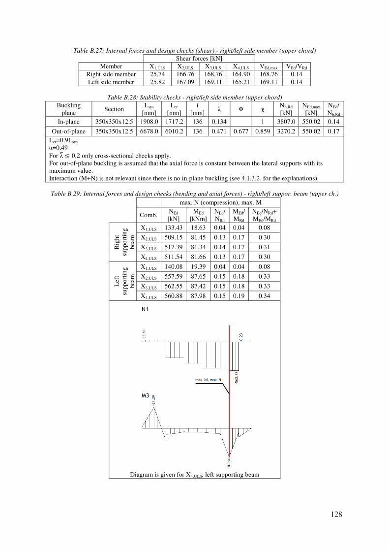
Table B.27: Internal forces and design checks (shear)
Member
Right side member Left side member
Table B.28: Stability checks
Buckling plane
Section
In-plane 350x350x12.5 1908.0
Out-of-plane 350x350x12.5 6678.0Lcr=0.9Lsys α=0.49 For λ� = 0.2 only cross-sectional checks apply.For out-of-plane buckling is assumed that the axial force is constant between the lateral supports with its maximum value. Interaction (M+N) is not relevant since there is no in
Table B.29: Internal forces and design checks (bending and axial forces)
Comb.
Rig
ht
supp
orti
ng
beam
Lef
t su
ppor
ting
be
am
Diagram is given for X
: Internal forces and design checks (shear) - right/left side member (upper chord)
Shear forces [kN] X1,ULS X2,ULS X3,ULS X4,ULS VEd,max 25.74 166.76 168.76 164.90 168.76 25.82 167.09 169.11 165.21 169.11
: Stability checks - right/left side member (upper chord)
Lsys
[mm] Lcr
[mm] i
[mm] λ� Φ χ N[kN]
1908.0 1717.2 136 0.134
1 3807.0
6678.0 6010.2 136 0.471 0.677 0.859 3270.2
sectional checks apply. assumed that the axial force is constant between the lateral supports with its
Interaction (M+N) is not relevant since there is no in-plane buckling (see 4.1.3.2. for the explanations)
: Internal forces and design checks (bending and axial forces) - right/left suppor. beam (upper ch.)
max. N (compression), max. M
Comb. NEd
[kN] MEd
[kNm] NEd/ NRd
MEd/ MRd
NEd/NRd+ MEd/MRd
X1,ULS 133.43 18.63 0.04 0.04 0.08
X2,ULS 509.15 81.45 0.13 0.17 0.30
X3,ULS 517.39 81.34 0.14 0.17 0.31
X4,ULS 511.54 81.66 0.13 0.17 0.30
X1,ULS 140.08 19.39 0.04 0.04 0.08
X2,ULS 557.59 87.65 0.15 0.18 0.33
X3,ULS 562.55 87.42 0.15 0.18 0.33
X4,ULS 560.88 87.98 0.15 0.19 0.34
Diagram is given for X4,ULS, left supporting beam
128
right/left side member (upper chord)
VEd/VRd
0.14 0.14
right/left side member (upper chord)
Nb,Rd
[kN] NEd,max
[kN] NEd/ Nb,Rd
3807.0 550.02 0.14
3270.2 550.02 0.17
assumed that the axial force is constant between the lateral supports with its
plane buckling (see 4.1.3.2. for the explanations)
right/left suppor. beam (upper ch.)

Table B.30: Internal forces and design checks (shear)
Member
Right supporting beamLeft supporting beam
Table B.31: Stability checks
Buckling plane
Section
In-plane 350x350x12.5 1908.0
Out-of-plane 350x350x12.5 6678.0Lcr=0.9Lsys α=0.49 For λ� = 0.2 only cross-sectional checks apply.For out-of-plane buckling is assumed that the axial force is constant between the lateral supports with its maximum value. Interaction (M+N) is not relevant since
Table B.32: Internal forces and design checks (bending and axial forces)
Comb.
C1
C2
: Internal forces and design checks (shear) - right/left supporting beam (upper chord)
Shear forces [kN] X1,ULS X2,ULS X3,ULS X4,ULS VEd,max
Right supporting beam 20.14 80.05 80.32 79.90 80.32 19.88 81.42 81.63 81.33 81.63
: Stability checks - right/left supporting beam (upper chord)
Lsys
[mm] Lcr
[mm] i
[mm] λ� Φ χ N[kN]
1908.0 1717.2 136 0.134
1 3807.0
6678.0 6010.2 136 0.471 0.677 0.859 3270.2
sectional checks apply. is assumed that the axial force is constant between the lateral supports with its
Interaction (M+N) is not relevant since there is no in-plane buckling (see 4.1.3.2. for the explanations)
: Internal forces and design checks (bending and axial forces) - connecting beam (upper chord)
max. N (compression), max. M
Comb. NEd
[kN] MEd
[kNm] NEd/ NRd
MEd/ MRd
NEd/NRd+ MEd/MRd
X1,ULS 124.28 12.35 0.03 0.03 0.06
X2,ULS 598.17 51.18 0.16 0.11 0.27
X3,ULS 555.20 50.83 0.15 0.11 0.26
X4,ULS 641.94 51.61 0.17 0.11 0.28
X1,ULS 115.69 13.83 0.03 0.03 0.06
X2,ULS 479.29 70.63 0.13 0.15 0.28
X3,ULS 495.87 70.75 0.13 0.15 0.28
X4,ULS 463.44 70.59 0.12 0.15 0.27
C1, X4,ULS
129
right/left supporting beam (upper chord)
VEd/VRd
0.07 0.07
right/left supporting beam (upper chord)
Nb,Rd
[kN] NEd,max
[kN] NEd/ Nb,Rd
3807.0 562.55 0.15
3270.2 562.55 0.17
is assumed that the axial force is constant between the lateral supports with its
plane buckling (see 4.1.3.2. for the explanations)
connecting beam (upper chord)
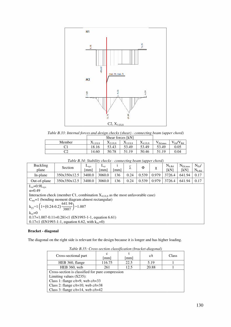
Table B.33: Internal forces and design checks (shear)
Member
C1 C2
Table B.34
Buckling plane
Section
In-plane 350x350x12.5 3400.0
Out-of-plane 350x350x12.5 3400.0Lcr=0.9Lsys α=0.49 Interaction check (member C1, combination XCmy=1 (bending moment diagram almost rectangular)
kyy=1 �1+(0.24-0.2) 641.94
3807 =1.007
kzy=0 0.17+1.007·0.11=0.281<1 (EN19930.17<1 (EN1993-1-1, equation 6.62, with k
Bracket - diagonal
The diagonal on the right side is relevant for the design because it is longer and has higher loading.
Table B.35
Cross-sectional part
HEB 360, flangeHEB 360, web
Cross-section is classified for pure compressionLimiting values (S235):Class 1: flange c/t=9, web c/t=33Class 2: flange c/t=10, web c/t=38Class 3: flange c/t=14, web c/t=42
C2, X3,ULS
: Internal forces and design checks (shear) - connecting beam (upper chord)
Shear forces [kN] X1,ULS X2,ULS X3,ULS X4,ULS VEd,max 18.16 53.43 53.49 53.49 53.49 14.60 50.78 51.19 50.46 51.19
34: Stability checks - connecting beam (upper chord)
Lsys
[mm] Lcr
[mm] i
[mm] λ� Φ χ N[kN]
3400.0 3060.0 136 0.24 0.539 0.979 3726.4
3400.0 3060.0 136 0.24 0.539 0.979 3726.4
Interaction check (member C1, combination X4,ULS as the most unfavorable case) =1 (bending moment diagram almost rectangular)
007
0.17+1.007·0.11=0.281<1 (EN1993-1-1, equation 6.61) 1, equation 6.62, with kzy=0)
The diagonal on the right side is relevant for the design because it is longer and has higher loading.
35: Cross-section classification (bracket-diagonal)
al part c
[mm] t
[mm] c/t
HEB 360, flange 116.75 22.5 5.19 261 12.5 20.88
section is classified for pure compression Limiting values (S235):
c/t=9, web c/t=33 Class 2: flange c/t=10, web c/t=38 Class 3: flange c/t=14, web c/t=42
130
beam (upper chord)
VEd/VRd
0.05 0.04
Nb,Rd
[kN] NEd,max
[kN] NEd/ Nb,Rd
3726.4 641.94 0.17
3726.4 641.94 0.17
The diagonal on the right side is relevant for the design because it is longer and has higher loading.
Class
1 1
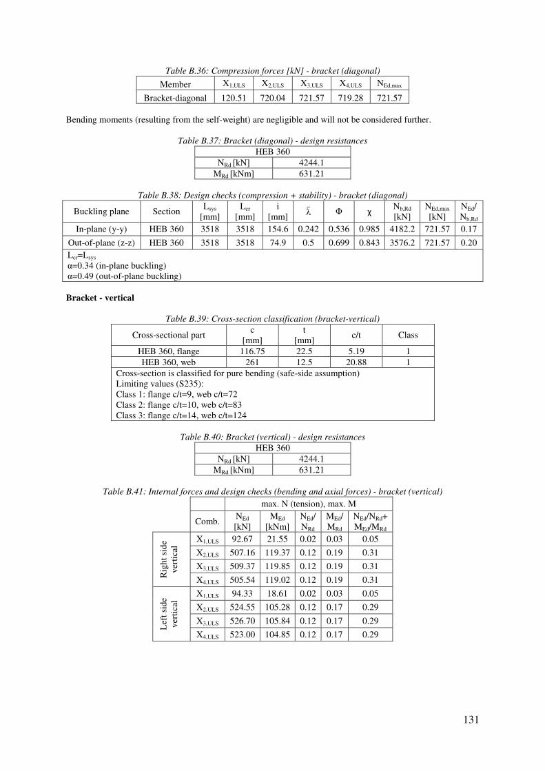
131
Table B.36: Compression forces [kN] - bracket (diagonal)
Member X1,ULS X2,ULS X3,ULS X4,ULS NEd,max
Bracket-diagonal 120.51 720.04 721.57 719.28 721.57 Bending moments (resulting from the self-weight) are negligible and will not be considered further.
Table B.37: Bracket (diagonal) - design resistances
HEB 360 NRd [kN] 4244.1
MRd [kNm] 631.21
Table B.38: Design checks (compression + stability) - bracket (diagonal)
Buckling plane Section Lsys
[mm] Lcr
[mm] i
[mm] λ� Φ χ Nb,Rd
[kN] NEd,max
[kN] NEd/ Nb,Rd
In-plane (y-y) HEB 360 3518 3518 154.6 0.242 0.536 0.985 4182.2 721.57 0.17
Out-of-plane (z-z) HEB 360 3518 3518 74.9 0.5 0.699 0.843 3576.2 721.57 0.20 Lcr=Lsys α=0.34 (in-plane buckling) α=0.49 (out-of-plane buckling) Bracket - vertical
Table B.39: Cross-section classification (bracket-vertical)
Cross-sectional part c
[mm] t
[mm] c/t Class
HEB 360, flange 116.75 22.5 5.19 1 HEB 360, web 261 12.5 20.88 1
Cross-section is classified for pure bending (safe-side assumption) Limiting values (S235): Class 1: flange c/t=9, web c/t=72 Class 2: flange c/t=10, web c/t=83 Class 3: flange c/t=14, web c/t=124
Table B.40: Bracket (vertical) - design resistances
HEB 360 NRd [kN] 4244.1
MRd [kNm] 631.21
Table B.41: Internal forces and design checks (bending and axial forces) - bracket (vertical)
max. N (tension), max. M
Comb. NEd
[kN] MEd
[kNm] NEd/ NRd
MEd/ MRd
NEd/NRd+ MEd/MRd
Rig
ht s
ide
vert
ical
X1,ULS 92.67 21.55 0.02 0.03 0.05
X2,ULS 507.16 119.37 0.12 0.19 0.31
X3,ULS 509.37 119.85 0.12 0.19 0.31
X4,ULS 505.54 119.02 0.12 0.19 0.31
Lef
t sid
e ve
rtic
al
X1,ULS 94.33 18.61 0.02 0.03 0.05
X2,ULS 524.55 105.28 0.12 0.17 0.29
X3,ULS 526.70 105.84 0.12 0.17 0.29
X4,ULS 523.00 104.85 0.12 0.17 0.29

Table
Combination X3,ULS is the most unfavorable case in bendingMcr=13819.31 kNm
λ�LT=� 631.21
13819.31=0.214
For λ�LT = 0.4 lateral-torsional buckling check is not necessary Bracket - horizontal
Table B.43
Cross-sectional part
HEA 800, flangeHEA 800, web
Cross-section is classified for bending (safeLimiting values (S235):Class 1: flange c/t=9, web c/t=72Class 2: flange c/t=10, web c/t=83Class 3: flange c/t=14, web c/t=124
Table
Table B.45: Internal forces and design checks (bending and axial forces)
Comb.
Rig
ht s
ide
hori
zont
al X
X
X
X
Lef
t sid
e ho
rizo
ntal
X
X
X
X
Right side vertical, X3,ULS
Table B.42: Stability checks - bracket (vertical)
is the most unfavorable case in bending
torsional buckling check is not necessary
43: Cross-section classification (bracket-horizontal)
al part c
[mm] t
[mm] c/t
HEA 800, flange 112.5 28 4.02 337 15 22.47
section is classified for bending (safe-side assumption) Limiting values (S235): Class 1: flange c/t=9, web c/t=72 Class 2: flange c/t=10, web c/t=83 Class 3: flange c/t=14, web c/t=124
Table B.44: Bracket (horizontal) - design resistances
HEA 800 NRd [kN] 6716.3
MRd [kNm] 2044.27
: Internal forces and design checks (bending and axial forces) - bracket (horizontal)
max. N (tension), max. M
Comb. NEd
[kN] MEd
[kNm] NEd/ NRd
MEd/ MRd
NEd/NRd+ MEd/MRd
X1,ULS 89.87 80.32 0.01 0.04 0.05
X2,ULS 540.38 440.65 0.08 0.22 0.30
X3,ULS 544.21 445.17 0.08 0.22 0.30
X4,ULS 537.13 436.64 0.08 0.21 0.29
X1,ULS 72.58 70.34 0.01 0.03 0.04
X2,ULS 440.80 389.52 0.07 0.19 0.26
X3,ULS 444.88 394.58 0.07 0.19 0.26
X4,ULS 437.18 384.94 0.07 0.19 0.26
132
Class
1 1
bracket (horizontal)

Table
Combination X3,ULS is the most unfavorable case in bendingMcr=27638.3 kNm
λ�LT=�2044.27
27638.3=0.272
For λ�LT = 0.4 lateral-torsional buckling check is not necessary Design of joints
Right/left side
member
Right/left supporting
beam
Connecting beam
Right side horizontal, X3,ULS
Table B.46: Stability checks - bracket (horizontal)
is the most unfavorable case in bending
torsional buckling check is not necessary
Table B.47: Designation - joints
133
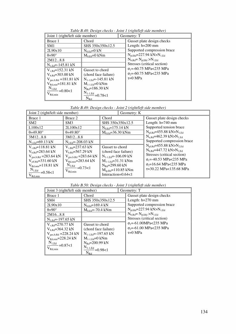
134
Table B.48: Design checks - Joint 1 (right/left side member)
Joint 1 (right/left side member) Geometry: T Brace 1 Chord Gusset plate design checks
Length: h=200 mm Supported compression brace Npl,Rd=227.94 kN>N1,Ed Nb,Rd= Npl,Rd >N1,Ed Stresses (critical section) σ1=-60.75 MPa<235 MPa σ2=-60.75 MPa<235 MPa τ=0 MPa
SM1 SHS 350x350x12.5
2L90x10 N0,Ed=0 kN θ=90° M0,Ed=0 kNm 2M12...8.8 N1,Ed=-145.81 kN Vv,Rd=152.31 kN Vb,Rd=303.00 kN Vgus,b,Rd =181.81 kN VRd,min=181.81 kN N1,Ed
VRd,min=0.80<1
Gusset to chord (chord face failure) N1-1,Ed=-145.81 kN M1-1,Ed=0 kNm NRd=186.30 kN N1-1,Ed
NRd=0.78<1
Table B.49: Design checks - Joint 2 (right/left side member)
Joint 2 (right/left side member) Geometry: K Brace 1 Brace 2 Chord Gusset plate design checks
Length: h=740 mm Supported tension brace Npl,Rd=455.88 kN>N1,Ed Nu,Rd=462.39 kN>N1,Ed Supported compression brace Npl,Rd=455.88 kN>N2,Ed Nb,Rd=447.72 kN>N2,Ed Stresses (critical section) σ1=-40.53 MPa<235 MPa σ2=16.64 MPa<235 MPa τ=30.22 MPa<135.68 MPa
SM2 SM3 SHS 350x350x12.5
L100x12 2L100x12 N0,Ed=175.14 kN θ=49.80° θ=49.80° M0,Ed=36.30 kNm 3M12...8.8 3M12...8.8 N1,Ed=69.13 kN N2,Ed=-208.03 kN Vv,Rd=118.81 kN Vb,Rd=283.64 kN Vgus,b,Rd =283.64 kN Veff,Rd=331.60 kN VRd,min=118.81 kN N1,Ed
VRd,min=0.58<1
Vv,Rd=237.63 kN Vb,Rd=567.29 kN Vgus,b,Rd =283.64 kN VRd,min=283.64 kN N2,Ed
VRd,min=0.73<1
Gusset to chord (chord face failure) N1-1,Ed=-106.09 kN M1-1,Ed=31.31 kNm NRd=299.60 kN Mip,Rd=110.85 kNm Interaction=0.64<1
Table B.50: Design checks - Joint 3 (right/left side member)
Joint 3 (right/left side member) Geometry: T Brace 1 Chord Gusset plate design checks
Length: h=270 mm Supported compression brace Npl,Rd=227.94 kN>N1,Ed Nb,Rd= Npl,Rd >N1,Ed Stresses (critical section) σ1=-61.00MPa<235 MPa σ2=-61.00 MPa<235 MPa τ=0 MPa
SM4 SHS 350x350x12.5
2L90x10 N0,Ed=169.4 kN θ=90° M0,Ed=-70.4 kNm 2M16...8.8 N1,Ed=-197.65 kN Vv,Rd=270.77 kN Vb,Rd=364.32 kN Vgus,b,Rd =228.24 kN VRd,min=228.24 kN N1,Ed
VRd,min=0.87<1
Gusset to chord (chord face failure) N1-1,Ed=-197.65 kN M1-1,Ed=0 kNm NRd=200.99 kN N1-1,Ed
NRd=0.98<1
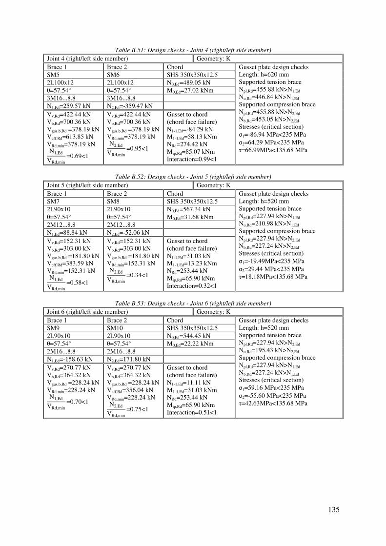
135
Table B.51: Design checks - Joint 4 (right/left side member)
Joint 4 (right/left side member) Geometry: K Brace 1 Brace 2 Chord Gusset plate design checks
Length: h=620 mm Supported tension brace Npl,Rd=455.88 kN>N1,Ed Nu,Rd=446.84 kN>N1,Ed Supported compression brace Npl,Rd=455.88 kN>N2,Ed Nb,Rd=453.05 kN>N2,Ed Stresses (critical section) σ1=-86.94 MPa<235 MPa σ2=64.29 MPa<235 MPa τ=66.99MPa<135.68 MPa
SM5 SM6 SHS 350x350x12.5
2L100x12 2L100x12 N0,Ed=489.05 kN θ=57.54° θ=57.54° M0,Ed=27.02 kNm 3M16...8.8 3M16...8.8 N1,Ed=259.57 kN N2,Ed=-359.47 kN Vv,Rd=422.44 kN Vb,Rd=700.36 kN Vgus,b,Rd =378.19 kN Veff,Rd=613.85 kN VRd,min=378.19 kN N1,Ed
VRd,min=0.69<1
Vv,Rd=422.44 kN Vb,Rd=700.36 kN Vgus,b,Rd =378.19 kN VRd,min=378.19 kN N2,Ed
VRd,min=0.95<1
Gusset to chord (chord face failure) N1-1,Ed=-84.29 kN M1-1,Ed=58.13 kNm NRd=274.42 kN Mip,Rd=85.07 kNm Interaction=0.99<1
Table B.52: Design checks - Joint 5 (right/left side member)
Joint 5 (right/left side member) Geometry: K Brace 1 Brace 2 Chord Gusset plate design checks
Length: h=520 mm Supported tension brace Npl,Rd=227.94 kN>N1,Ed Nu,Rd=210.98 kN>N1,Ed Supported compression brace Npl,Rd=227.94 kN>N2,Ed Nb,Rd=227.24 kN>N2,Ed Stresses (critical section) σ1=-19.49MPa<235 MPa σ2=29.44 MPa<235 MPa τ=18.18MPa<135.68 MPa
SM7 SM8 SHS 350x350x12.5
2L90x10 2L90x10 N0,Ed=567.34 kN θ=57.54° θ=57.54° M0,Ed=31.68 kNm 2M12...8.8 2M12...8.8 N1,Ed=88.84 kN N2,Ed=-52.06 kN Vv,Rd=152.31 kN Vb,Rd=303.00 kN Vgus,b,Rd =181.80 kN Veff,Rd=383.59 kN VRd,min=152.31 kN N1,Ed
VRd,min=0.58<1
Vv,Rd=152.31 kN Vb,Rd=303.00 kN Vgus,b,Rd =181.80 kN VRd,min=152.31 kN N2,Ed
VRd,min=0.34<1
Gusset to chord (chord face failure) N1-1,Ed=31.03 kN M1-1,Ed=13.23 kNm NRd=253.44 kN Mip,Rd=65.90 kNm Interaction=0.32<1
Table B.53: Design checks - Joint 6 (right/left side member)
Joint 6 (right/left side member) Geometry: K Brace 1 Brace 2 Chord Gusset plate design checks
Length: h=520 mm Supported tension brace Npl,Rd=227.94 kN>N2,Ed Nu,Rd=195.43 kN>N2,Ed Supported compression brace Npl,Rd=227.94 kN>N1,Ed Nb,Rd=227.24 kN>N1,Ed Stresses (critical section) σ1=59.16 MPa<235 MPa σ2=-55.60 MPa<235 MPa τ=42.63MPa<135.68 MPa
SM9 SM10 SHS 350x350x12.5
2L90x10 2L90x10 N0,Ed=544.45 kN θ=57.54° θ=57.54° M0,Ed=22.22 kNm 2M16...8.8 2M16...8.8 N1,Ed=-158.63 kN N2,Ed=171.80 kN Vv,Rd=270.77 kN Vb,Rd=364.32 kN Vgus,b,Rd =228.24 kN VRd,min=228.24 kN N1,Ed
VRd,min=0.70<1
Vv,Rd=270.77 kN Vb,Rd=364.32 kN Vgus,b,Rd =228.24 kN Veff,Rd=356.04 kN VRd,min=228.24 kN N2,Ed
VRd,min=0.75<1
Gusset to chord (chord face failure) N1-1,Ed=11.11 kN M1-1,Ed=31.03 kNm NRd=253.44 kN Mip,Rd=65.90 kNm Interaction=0.51<1
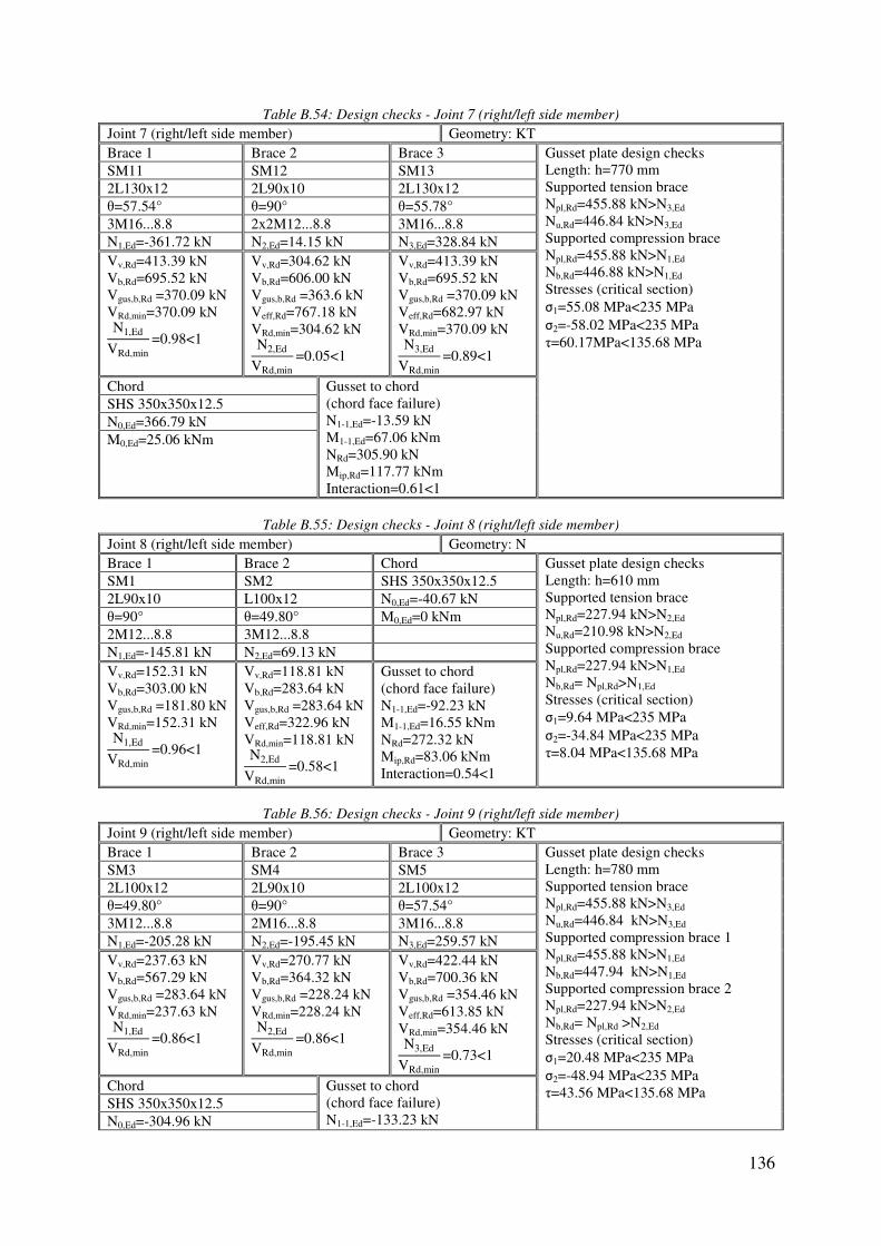
136
Table B.54: Design checks - Joint 7 (right/left side member)
Joint 7 (right/left side member) Geometry: KT Brace 1 Brace 2 Brace 3 Gusset plate design checks
Length: h=770 mm Supported tension brace Npl,Rd=455.88 kN>N3,Ed Nu,Rd=446.84 kN>N3,Ed Supported compression brace Npl,Rd=455.88 kN>N1,Ed Nb,Rd=446.88 kN>N1,Ed Stresses (critical section) σ1=55.08 MPa<235 MPa σ2=-58.02 MPa<235 MPa τ=60.17MPa<135.68 MPa
SM11 SM12 SM13 2L130x12 2L90x10 2L130x12 θ=57.54° θ=90° θ=55.78° 3M16...8.8 2x2M12...8.8 3M16...8.8 N1,Ed=-361.72 kN N2,Ed=14.15 kN N3,Ed=328.84 kN Vv,Rd=413.39 kN Vb,Rd=695.52 kN Vgus,b,Rd =370.09 kN VRd,min=370.09 kN N1,Ed
VRd,min=0.98<1
Vv,Rd=304.62 kN Vb,Rd=606.00 kN Vgus,b,Rd =363.6 kN Veff,Rd=767.18 kN VRd,min=304.62 kN N2,Ed
VRd,min=0.05<1
Vv,Rd=413.39 kN Vb,Rd=695.52 kN Vgus,b,Rd =370.09 kN Veff,Rd=682.97 kN VRd,min=370.09 kN N3,Ed
VRd,min=0.89<1
Chord Gusset to chord (chord face failure) N1-1,Ed=-13.59 kN M1-1,Ed=67.06 kNm NRd=305.90 kN Mip,Rd=117.77 kNm Interaction=0.61<1
SHS 350x350x12.5
N0,Ed=366.79 kN M0,Ed=25.06 kNm
Table B.55: Design checks - Joint 8 (right/left side member)
Joint 8 (right/left side member) Geometry: N Brace 1 Brace 2 Chord Gusset plate design checks
Length: h=610 mm Supported tension brace Npl,Rd=227.94 kN>N2,Ed Nu,Rd=210.98 kN>N2,Ed Supported compression brace Npl,Rd=227.94 kN>N1,Ed Nb,Rd= Npl,Rd>N1,Ed Stresses (critical section) σ1=9.64 MPa<235 MPa σ2=-34.84 MPa<235 MPa τ=8.04 MPa<135.68 MPa
SM1 SM2 SHS 350x350x12.5
2L90x10 L100x12 N0,Ed=-40.67 kN θ=90° θ=49.80° M0,Ed=0 kNm 2M12...8.8 3M12...8.8 N1,Ed=-145.81 kN N2,Ed=69.13 kN Vv,Rd=152.31 kN Vb,Rd=303.00 kN Vgus,b,Rd =181.80 kN VRd,min=152.31 kN N1,Ed
VRd,min=0.96<1
Vv,Rd=118.81 kN Vb,Rd=283.64 kN Vgus,b,Rd =283.64 kN Veff,Rd=322.96 kN VRd,min=118.81 kN N2,Ed
VRd,min=0.58<1
Gusset to chord (chord face failure) N1-1,Ed=-92.23 kN M1-1,Ed=16.55 kNm NRd=272.32 kN Mip,Rd=83.06 kNm Interaction=0.54<1
Table B.56: Design checks - Joint 9 (right/left side member)
Joint 9 (right/left side member) Geometry: KT Brace 1 Brace 2 Brace 3 Gusset plate design checks
Length: h=780 mm Supported tension brace Npl,Rd=455.88 kN>N3,Ed Nu,Rd=446.84 kN>N3,Ed Supported compression brace 1 Npl,Rd=455.88 kN>N1,Ed Nb,Rd=447.94 kN>N1,Ed
Supported compression brace 2 Npl,Rd=227.94 kN>N2,Ed Nb,Rd= Npl,Rd >N2,Ed Stresses (critical section) σ1=20.48 MPa<235 MPa σ2=-48.94 MPa<235 MPa τ=43.56 MPa<135.68 MPa
SM3 SM4 SM5 2L100x12 2L90x10 2L100x12 θ=49.80° θ=90° θ=57.54° 3M12...8.8 2M16...8.8 3M16...8.8 N1,Ed=-205.28 kN N2,Ed=-195.45 kN N3,Ed=259.57 kN Vv,Rd=237.63 kN Vb,Rd=567.29 kN Vgus,b,Rd =283.64 kN VRd,min=237.63 kN N1,Ed
VRd,min=0.86<1
Vv,Rd=270.77 kN Vb,Rd=364.32 kN Vgus,b,Rd =228.24 kN VRd,min=228.24 kN N2,Ed
VRd,min=0.86<1
Vv,Rd=422.44 kN Vb,Rd=700.36 kN Vgus,b,Rd =354.46 kN Veff,Rd=613.85 kN VRd,min=354.46 kN N3,Ed
VRd,min=0.73<1
Chord Gusset to chord (chord face failure) N1-1,Ed=-133.23 kN
SHS 350x350x12.5
N0,Ed=-304.96 kN

137
M0,Ed=26.85 kNm M1-1,Ed=42.23 kNm NRd=308.00 kN Mip,Rd=120.11 kNm Interaction=0.78<1
Table B.57: Design checks - Joint 10 (right/left side member)
Joint 10 (right/left side member) Geometry: K Brace 1 Brace 2 Chord Gusset plate design checks
Length: h=800 mm Supported tension brace Npl,Rd=227.94 kN>N2,Ed Nu,Rd=210.98 kN>N2,Ed Supported compression brace Npl,Rd=455.88 kN>N1,Ed Nb,Rd=452.96 kN>N1,Ed Stresses (critical section) σ1=0.19 MPa<235 MPa σ2=-47.76 MPa<235 MPa τ=37.60 MPa<135.68 MPa
SM6 SM7 SHS 350x350x12.5
2L100x12 2L90x10 N0,Ed=-541.27 kN θ=57.54° θ=57.54° M0,Ed=19.21 kNm 3M16...8.8 2M12...8.8 N1,Ed=-359.47 kN N2,Ed=88.84 kN Vv,Rd=422.44 kN Vb,Rd=700.36 kN Vgus,b,Rd =378.19 kN VRd,min=378.19 kN N1,Ed
VRd,min=0.95<1
Vv,Rd=152.31 kN Vb,Rd=303.00 kN Vgus,b,Rd =181.80 kN Veff,Rd=383.59 kN VRd,min=152.31 kN N2,Ed
VRd,min=0.58<1
Gusset to chord (chord face failure) N1-1,Ed=-228.35 kN M1-1,Ed=30-68 kNm NRd=312-19 kN Mip,Rd=124-88 kNm Interaction=0.98<1
Table B.58: Design checks - Joint 11 (right/left side member)
Joint 11 (right/left side member) Geometry: K Brace 1 Brace 2 Chord Gusset plate design checks
Length: h=600 mm Supported compression brace 1 Npl,Rd=227.94 kN>N1,Ed Nu,Rd=227.29 kN>N1,Ed Supported compression brace 2 Npl,Rd=227.94 kN>N2,Ed Nb,Rd=227.29 kN>N2,Ed Stresses (critical section) σ1=-38.83 MPa<235 MPa σ2=-6.34 MPa<235 MPa τ=13.93MPa<135.68 MPa
SM8 SM9 SHS 350x350x12.5
2L90x10 2L90x10 N0,Ed=-480.53 kN θ=57.54° θ=57.54° M0,Ed=-1.01 kNm 2M12...8.8 2M16...8.8 N1,Ed=-34.09 kN N2,Ed=-158.63 kN Vv,Rd=152.31 kN Vb,Rd=300.00 kN Vgus,b,Rd =181.80 kN VRd,min=152.31 kN N1,Ed
VRd,min=0.22<1
Vv,Rd=270.77 kN Vb,Rd=364.32 kN Vgus,b,Rd =227.90 kN VRd,min=227.90 kN N2,Ed
VRd,min=0.70<1
Gusset to chord (chord face failure) N1-1,Ed=-162.61 kN M1-1,Ed=11.70 kNm NRd=270.23 kN Mip,Rd=81.07 kNm Interaction=0.75<1
Table B.59: Design checks - Joint 12 (right/left side member)
Joint 12 (right/left side member) Geometry: K Brace 1 Brace 2 Chord Gusset plate design checks
Length: h=700 mm Supported tension brace Npl,Rd=227.94 kN>N1,Ed Nu,Rd=195.43 kN>N1,Ed Supported compression brace Npl,Rd=455.88 kN>N2,Ed Nb,Rd=446.88 kN>N2,Ed Stresses (critical section) σ1=-63.66 MPa<235 MPa σ2=25.51 MPa<235 MPa τ=51.13 MPa<135.68 MPa
SM10 SM11 SHS 350x350x12.5
2L90x10 2L130x12 N0,Ed=-480.82 kN θ=57.54° θ=57.54° M0,Ed=-7.82 kNm 2M16...8.8 3M16...8.8 N1,Ed=171.80 kN N2,Ed=-361.72 kN Vv,Rd=270.77 kN Vb,Rd=364.32 kN Vgus,b,Rd =228.24 kN Veff,Rd=356.04 kN VRd,min=228.24 kN N1,Ed
VRd,min=0.75<1
Vv,Rd=413.39 kN Vb,Rd=695.52 kN Vgus,b,Rd =370.09 kN VRd,min=370.09 kN N2,Ed
VRd,min=0.98<1
Gusset to chord (chord face failure) N1-1,Ed=-160.24 kN M1-1,Ed=43.69 kNm NRd=291.21 kN Mip,Rd=101.92 kNm Interaction=0.98<1

138
Table B.60: Design checks - Joint 13 (right/left side member)
Joint 13 (right/left side member) Geometry: N Brace 1 Brace 2 Chord Gusset plate design checks
Length: h=450 mm Supported tension brace Npl,Rd=455.88 kN>N1,Ed Nu,Rd=446.84 kN>N1,Ed Supported compression brace Npl,Rd=227.94 kN>N2,Ed Nb,Rd= 202.16 kN>N2,Ed Stresses (critical section) σ1=-36.55 MPa<235 MPa σ2=76.89 MPa<235 MPa τ=52.90 MPa<135.68 MPa
SM13 SM14 SHS 350x350x12.5
2L130x12 2L90x10 N0,Ed=-211.54 kN θ=55.78° θ=90° M0,Ed=-9.33kNm 3M16...8.8 2x2M12...8.8 N1,Ed=338.68 kN N2,Ed=-171.07 kN Vv,Rd=413.39 kN Vb,Rd=695.52 kN Vgus,b,Rd =347.76 kN Veff,Rd=665.69 kN VRd,min=347.76 kN N1,Ed
VRd,min=0.97<1
Vv,Rd=304.60 kN Vb,Rd=606.00 kN Vgus,b,Rd =363.60 kN VRd,min=304.60 kN N2,Ed
VRd,min=0.56<1
Gusset to chord (chord face failure) N1-1,Ed=108.93 kN M1-1,Ed=22.97 kNm NRd=238.75 kN Mip,Rd=53.72 kNm Interaction=0.88<1
Table B.61: Design checks - Joint 1 (right/left supporting beam)
Joint 1 (right/left supporting beam) Geometry: T Brace 1 Chord Gusset plate design checks
Length: h=200 mm Supported tension brace Npl,Rd=227.94 kN>N1,Ed Nu,Rd= 210.98 kN >N1,Ed Stresses (critical section) σ1=42.07 MPa<235 MPa σ2=42.07 MPa<235 MPa τ=0 MPa
SB1 SHS 350x350x12.5
2L90x10 N0,Ed=19.25 kN θ=90° M0,Ed=9.57 kNm 2M12...8.8 N1,Ed=100.96 kN Vv,Rd=152.31 kN Vb,Rd=303.00 kN Vgus,b,Rd =181.81 kN Veff,Rd=383.59 kN VRd,min=152.32 kN N1,Ed
VRd,min=0.66<1
Gusset to chord (chord face failure) N1-1,Ed=100.96 kN M1-1,Ed=0 kNm NRd=186.30 kN N1-1,Ed
NRd=0.54<1
Table B.62: Design checks - Joint 2 (right/left supporting beam)
Joint 2 (right/left supporting beam) Geometry: KT Brace 1 Brace 2 Brace 3 Gusset plate design checks
Length: h=790 mm Supported compression brace 1 Npl,Rd=455.88 kN>N1,Ed Nu,Rd=446.68 kN>N1,Ed Supported compression brace 2 Npl,Rd=227.94 kN>N2,Ed Nb,Rd= Npl,Rd>N2,Ed
Supported compression brace 3 Npl,Rd=455.88 kN>N3,Ed Nb,Rd= 446.68 kN >N3,Ed Stresses (critical section) σ1=-77.10 MPa<235 MPa σ2=-23.66 MPa<235 MPa τ=30.15 MPa<135.68 MPa
SB2 SB3 SB4 L100x12 2L90x10 2L90x10 θ=49.80° θ=90° θ=49.80° 3M12...8.8 2M12...8.8 3M16...8.8 N1,Ed=-76.40 kN N2,Ed=-135.38 kN N3,Ed=-371.66 kN Vv,Rd=118.81 kN Vb,Rd=283.64 kN Vgus,b,Rd =283.64 kN VRd,min=118.81 kN N1,Ed
VRd,min=0.64<1
Vv,Rd=152.32 kN Vb,Rd=303.00 kN Vgus,b,Rd =181.80 kN VRd,min=152.32 kN N2,Ed
VRd,min=0.89<1
Vv,Rd=428.40 kN Vb,Rd=582.06 kN Vgus,b,Rd =383.53 kN VRd,min=383.53 kN N3,Ed
VRd,min=0.97<1
Chord Gusset to chord (chord face failure) N1-1,Ed=-477.61 kN M1-1,Ed=33.35 kNm Stiffened by a plate tp=32 mm; bp=190 mm NRd=579.83 kN Mip,Rd=235.46 kNm Interaction=0.97<1
SHS 350x350x12.5
N0,Ed=212.33 kN M0,Ed=-118.61 kNm

139
Table B.63: Design checks - Joint 3 (right/left supporting beam)
Joint 3 (right/left supporting beam) Geometry: T Brace 1 Chord Gusset plate design checks
Length: h=200 mm Supported tension brace Npl,Rd=227.94 kN>N1,Ed Nu,Rd= 210.98 kN >N1,Ed Stresses (critical section) σ1=30.69 MPa<235 MPa σ2=30.69 MPa<235 MPa τ=0 MPa
SB5 SHS 350x350x12.5
2L90x10 N0,Ed=199.03 kN θ=90° M0,Ed=72.91 kNm 2M12...8.8 N1,Ed=73.66 kN Vv,Rd=152.31 kN Vb,Rd=303.00 kN Vgus,b,Rd =181.81 kN Veff,Rd=383.59 kN VRd,min=152.32 kN N1,Ed
VRd,min=0.48<1
Gusset to chord (chord face failure) N1-1,Ed=73.66 kN M1-1,Ed=0 kNm NRd=186.30 kN N1-1,Ed
NRd=0.40<1
Table B.64: Design checks - Joint 4 (right/left supporting beam)
Joint 4 (right/left supporting beam) Geometry: K Brace 1 Brace 2 Chord Gusset plate design checks
Length: h=600 mm Supported tension brace Npl,Rd=455.88 kN>N1,Ed Nu,Rd=462.39 kN>N1,Ed Supported compression brace Npl,Rd=227.94 kN>N2,Ed Nb,Rd=227.10 kN>N2,Ed Stresses (critical section) σ1=-29.58 MPa<235 MPa σ2=52.50 MPa<235 MPa τ=35.18 MPa<135.68 MPa
SB6 SB7 SHS 350x350x12.5
2L90x10 L100x12 N0,Ed=392.79 kN θ=57.54° θ=57.54° M0,Ed=3.46 kNm 3M12...8.8 2M16...8.8 N1,Ed=206.23 kN N2,Ed=-108.44 kN Vv,Rd=240.98 kN Vb,Rd=479.41 kN Vgus,b,Rd =287.65 kN Veff,Rd=538.26 kN VRd,min=240.98 kN N1,Ed
VRd,min=0.86<1
Vv,Rd=132.41 kN Vb,Rd=219.52 kN Vgus,b,Rd =223.78 kN VRd,min=132.41 kN N2,Ed
VRd,min=0.82<1
Gusset to chord (chord face failure) N1-1,Ed=82.51 kN M1-1,Ed=29.55 kNm NRd=270.22 kN Mip,Rd=81.07 kNm Interaction=0.67<1
Table B.65: Design checks - Joint 5 (right/left supporting beam)
Joint 5 (right/left supporting beam) Geometry: K Brace 1 Brace 2 Chord Gusset plate design checks
Length: h=520 mm Supported tension brace Npl,Rd=227.94 kN>N1,Ed Nu,Rd=195.43 kN>N1,Ed Supported compression brace Npl,Rd=227.94 kN>N2,Ed Nb,Rd=227.10 kN>N2,Ed Stresses (critical section) σ1=-32.38 MPa<235 MPa σ2=33.69 MPa<235 MPa τ=24.54 MPa<135.68 MPa
SB8 SB9 SHS 350x350x12.5
L100x12 L100x12 N0,Ed=495.20 kN θ=57.54° θ=57.54° M0,Ed=12.45 kNm 2M16...8.8 2M16...8.8 N1,Ed=97.54 kN N2,Ed=-92.70 kN Vv,Rd=132.41 kN Vb,Rd=219.52 kN Vgus,b,Rd =223.13 kN Veff,Rd=222.26 kN VRd,min=132.41 kN N1,Ed
VRd,min=0.74<1
Vv,Rd=132.41 kN Vb,Rd=219.52 kN Vgus,b,Rd =223.78 kN VRd,min=132.41 kN N2,Ed
VRd,min=0.70<1
Gusset to chord (chord face failure) N1-1,Ed=4.09 kN M1-1,Ed=17.87 kNm NRd=253.44 kN Mip,Rd=65.90 kNm Interaction=0.29<1

140
Table B.66: Design checks - Joint 6 (right/left supporting beam)
Joint 6 (right/left supporting beam) Geometry: K Brace 1 Brace 2 Chord Gusset plate design checks
Length: h=520 mm Supported tension brace Npl,Rd=227.94 kN>N1,Ed Nu,Rd=195.43 kN>N1,Ed Supported compression brace Npl,Rd=227.94 kN>N2,Ed Nb,Rd=227.10 kN>N2,Ed Stresses (critical section) σ1=-29.00 MPa<235 MPa σ2=29.53 MPa<235 MPa τ=21.74 MPa<135.68 MPa
SB10 SB11 SHS 350x350x12.5
L100x12 L100x12 N0,Ed=585.98 kN θ=57.54° θ=57.54° M0,Ed=21.08 kN 2M16...8.8 2M16...8.8 N1,Ed=85.23 kN N2,Ed=-83.28 kN Vv,Rd=132.41 kN Vb,Rd=219.52 kN Vgus,b,Rd =223.13 kN Veff,Rd=222.26 kN VRd,min=132.41 kN N1,Ed
VRd,min=0.64<1
Vv,Rd=132.41 kN Vb,Rd=219.52 kN Vgus,b,Rd =223.78 kN VRd,min=132.41 kN N2,Ed
VRd,min=0.63<1
Gusset to chord (chord face failure) N1-1,Ed=1.65 kN M1-1,Ed=15.83 kNm NRd=253.44 kN Mip,Rd=65.90 kNm Interaction=0.25<1
Table B.67: Design checks - Joint 7 (right/left supporting beam)
Joint 7 (right/left supporting beam) Geometry: KT Brace 1 Brace 2 Brace 3 Gusset plate design checks
Length: h=660 mm Supported tension brace Npl,Rd=455.88 kN>N3,Ed Nu,Rd=446.84 kN>N3,Ed Supported compression brace 1 Npl,Rd=227.94 kN>N1,Ed Nb,Rd=227.10 kN>N1,Ed
Supported compression brace 2 Npl,Rd=455.88 kN>N2,Ed Nb,Rd=418.72 kN>N2,Ed Stresses (critical section) σ1=38.29 MPa<235 MPa σ2=-15.34 MPa<235 MPa τ=31.19 MPa<135.68 MPa
SB12 SB13 SB14 L100x12 2L90x10 2L130x12 θ=57.54° θ=90° θ=55.78° 2M12...8.8 2x2M12...8.8 3M16...8.8 N1,Ed=-11.94 kN N2,Ed=-131.76 kN N3,Ed=281.45 kN Vv,Rd=74.48 kN Vb,Rd=177.81 kN Vgus,b,Rd =177.81 kN VRd,min=74.48 kN N1,Ed
VRd,min=0.15<1
Vv,Rd=304.62 kN Vb,Rd=606.00 kN Vgus,b,Rd =363.6 kN VRd,min=304.62 kN N2,Ed
VRd,min=0.43<1
Vv,Rd=413.39 kN Vb,Rd=695.52 kN Vgus,b,Rd =370.76 kN Veff,Rd=665.69 kN VRd,min=370.76 kN N3,Ed
VRd,min=0.76<1
Chord Gusset to chord (chord face failure) N1-1,Ed=90.89 kN M1-1,Ed=23.36 kNm NRd=282.82 kN Mip,Rd=93.33 kNm Interaction=0.57<1
SHS 350x350x12.5
N0,Ed=538.39 kN M0,Ed=23.31 KNm
Table B.68: Design checks - Joint 8 (right/left supporting beam)
Joint 8 (right/left supporting beam) Geometry: N Brace 1 Brace 2 Chord Gusset plate design checks
Length: h=750 mm Supported compression brace 1 Npl,Rd=830.35 kN>N1,Ed Nb,Rd =824.43 kN>N1,Ed Supported compression brace 2 Npl,Rd=227.94 kN>N2,Ed Nb,Rd= Npl,Rd>N2,Ed Stresses (critical section) σ1=33.15 MPa<235 MPa σ2=72.15 MPa<235 MPa τ=71.98 MPa<135.68 MPa
SB16 SB17 SHS 350x350x12.5
2L130x12 2L90x10 N0,Ed=372.01 kN θ=48.72° θ=90° M0,Ed=0 kNm 4M20...8.8 2M12...8.8 N1,Ed=-644.70 kN N2,Ed=-18.09 kN Vv,Rd=915.61 kN Vb,Rd=1015.43 kN Vgus,b,Rd =655.76 kN VRd,min=655.76kN N1,Ed
VRd,min=0.98<1
Vv,Rd=152.31 kN Vb,Rd=303.00 kN Vgus,b,Rd =178.04 kN VRd,min=178.04 kN N2,Ed
VRd,min=0.10<1
Gusset to chord (chord face failure) N1-1,Ed=-510.03 kN M1-1,Ed=13.67 kNm Stiffened by a plate tp=32 mm; bp=190 mm NRd=561.5 kN Mip,Rd=210.56 kNm Interaction=0.97<1

141
Table B.69: Design checks - Joint 9 (right/left supporting beam)
Joint 9 (right/left supporting beam) Geometry: N Brace 1 Brace 2 Chord Gusset plate design checks
Length: h=620 mm Supported tension brace Npl,Rd=227.94 kN>N1,Ed Nu,Rd=210.98 kN>N1,Ed Supported compression brace Npl,Rd=455.88 kN>N2,Ed Nb,Rd= 446.68 kN>N2,Ed Stresses (critical section) σ1=-14.92 MPa<235 MPa σ2=22.44 MPa<235 MPa τ=13.00 MPa<135.68 MPa
SB1 SB2 SHS 350x350x12.5
2L90x10 L100x12 N0,Ed=58.33 kN θ=90° θ=49.80° M0,Ed=0 kNm 2M12...8.8 3M12...8.8 N1,Ed=104.29 kN N2,Ed=-99.93 kN Vv,Rd=152.31 kN Vb,Rd=303.00 kN Vgus,b,Rd =181.80 kN Veff,Rd=383.59 kN VRd,min=152.31 kN N1,Ed
VRd,min=0.68<1
Vv,Rd=118.81 kN Vb,Rd=283.64 kN Vgus,b,Rd =283.64 kN Veff,Rd=322.96 kN VRd,min=118.81 kN N2,Ed
VRd,min=0.84<1
Gusset to chord (chord face failure) N1-1,Ed=27.96 kN M1-1,Ed=14.36 kNm NRd=274.42 kN Mip,Rd=85.07 kNm Interaction=0.27<1
Table B.70: Design checks - Joint 10 (right/left supporting beam)
Joint 10 (right/left supporting beam) Geometry: T Brace 1 Chord Gusset plate design checks
Length: h=200 mm Supported compression brace Npl,Rd=227.94 kN>N1,Ed Nb,Rd= Npl,Rd >N1,Ed Stresses (critical section) σ1=-56.41 MPa<235 MPa σ2=-56.41 MPa<235 MPa τ=0 MPa
SB3 SHS 350x350x12.5
2L90x10 N0,Ed=-43.52 kN θ=90° M0,Ed=66.23 kNm 2M12...8.8 N1,Ed=-135.38 kN Vv,Rd=152.31 kN Vb,Rd=303.00 kN Vgus,b,Rd =181.81 kN VRd,min=152.32 kN N1,Ed
VRd,min=0.89<1
Gusset to chord (chord face failure) N1-1,Ed=-135.38 kN M1-1,Ed=0 kNm NRd=186.30 kN N1-1,Ed
NRd=0.73<1
Table B.71: Design checks - Joint 11 (right/left supporting beam)
Joint 11 (right/left supporting beam) Geometry: KT Brace 1 Brace 2 Brace 3 Gusset plate design checks
Length: h=750 mm Supported compression brace Npl,Rd=455.88 kN>N1,Ed Nb,Rd= 448.63 kN >N1,Ed Supported tension brace 1 Npl,Rd=227.94 kN>N2,Ed Nu,Rd=210.98 kN>N2,Ed Supported tension brace 2 Npl,Rd=227.94 kN>N3,Ed Nu,Rd=210.98 kN>N3,Ed Stresses (critical section) σ1=48.65 MPa<235 MPa σ2=-57.84 MPa<235 MPa τ=58.43 MPa<135.68 MPa
SB4 SB5 SB6 2L90x10 2L90x10 2L90x10 θ=49.80° θ=90° θ=57.54° 3M16...8.8 2M12...8.8 3M12...8.8 N1,Ed=-371.66 kN N2,Ed=68.52 kN N3,Ed=206.23 kN Vv,Rd=428.40 kN Vb,Rd=582.06 kN Vgus,b,Rd =377.07 kN VRd,min=377.07 kN N1,Ed
VRd,min=0.99<1
Vv,Rd=152.31 kN Vb,Rd=300.00 kN Vgus,b,Rd =181.80 kN Veff,Rd=383.59 kN VRd,min=152.31 kN N2,Ed
VRd,min=0.45<1
Vv,Rd=240.98 kN Vb,Rd=479.41 kN Vgus,b,Rd =287.65 kN Veff,Rd=538.26 kN VRd,min=240.98 kN N3,Ed
VRd,min=0.86<1
Chord Gusset to chord (chord face failure) N1-1,Ed=-41.34 kN M1-1,Ed=59.90 kNm NRd=301.70 kN Mip,Rd=113.14 kNm Interaction=0.66<1
SHS 350x350x12.5
N0,Ed=-315.69 kN M0,Ed=-34.69 kNm

142
Table B.72: Design checks - Joint 12 (right/left supporting beam)
Joint 12 (right/left supporting beam) Geometry: K Brace 1 Brace 2 Chord Gusset plate design checks
Length: h=610 mm Supported compression brace Npl,Rd=227.94 kN>N1,Ed Nb,Rd=226.39 kN>N1,Ed Supported tension brace Npl,Rd=227.94 kN>N2,Ed Nu,Rd=195.43 kN>N2,Ed Stresses (critical section) σ1=24.74 MPa<235 MPa σ2=-27.25 MPa<235 MPa τ=22.65 MPa<135.68 MPa
SB7 SB8 SHS 350x350x12.5
L100x12 L100x12 N0,Ed=-425.90 kN θ=57.54° θ=57.54° M0,Ed=-11.80 kNm 2M16...8.8 2M16...8.8 N1,Ed=-108.44 kN N2,Ed=97.54 kN Vv,Rd=132.41 kN Vb,Rd=219.52 kN Vgus,b,Rd =223.78 kN VRd,min=132.41 kN N1,Ed
VRd,min=0.82<1
Vv,Rd=132.41 kN Vb,Rd=219.52 kN Vgus,b,Rd =223.78 kN Veff,Rd=222.26 kN VRd,min=132.41 kN N2,Ed
VRd,min=0.74<1
Gusset to chord (chord face failure) N1-1,Ed=-9.20 kN M1-1,Ed=19.34 kNm NRd=272.33 kN Mip,Rd=83.06 kNm Interaction=0.27<1
Table B.73: Design checks - Joint 13 (right/left supporting beam)
Joint 13 (right/left supporting beam) Geometry: K Brace 1 Brace 2 Chord Gusset plate design checks
Length: h=610 mm Supported compression brace Npl,Rd=227.94 kN>N1,Ed Nb,Rd=226.39 kN>N1,Ed Supported tension brace Npl,Rd=227.94 kN>N2,Ed Nu,Rd=195.43 kN>N2,Ed Stresses (critical section) σ1=21.59 MPa<235 MPa σ2=-23.32 MPa<235 MPa τ=19.57 MPa<135.68 MPa
SB9 SB10 SHS 350x350x12.5
L100x12 L100x12 N0,Ed=-521.07 kN θ=57.54° θ=57.54° M0,Ed=-12.71 kNm 2M16...8.8 2M16...8.8 N1,Ed=-92.72 kN N2,Ed=85.23 kN Vv,Rd=132.41 kN Vb,Rd=219.52 kN Vgus,b,Rd =223.78 kN VRd,min=132.41 kN N1,Ed
VRd,min=0.82<1
Vv,Rd=132.41 kN Vb,Rd=219.52 kN Vgus,b,Rd =223.78 kN Veff,Rd=222.26 kN VRd,min=132.41 kN N2,Ed
VRd,min=0.74<1
Gusset to chord (chord face failure) N1-1,Ed=-6.32 kN M1-1,Ed=16.71 kNm NRd=272.33 kN Mip,Rd=83.06 kNm Interaction=0.22<1
Table B.74: Design checks - Joint 14 (right/left supporting beam)
Joint 14 (right/left supporting beam) Geometry: K Brace 1 Brace 2 Chord Gusset plate design checks
Length: h=610 mm Supported compression brace 1 Npl,Rd=227.94 kN>N1,Ed Nb,Rd=226.39 kN>N1,Ed Supported compression brace 2 Npl,Rd=227.94 kN>N2,Ed Nb,Rd=226.39 kN>N2,Ed Stresses (critical section) σ1=0.39 MPa<235 MPa σ2=-20.05MPa<235 MPa τ=8.57 MPa<135.68 MPa
SB11 SB12 SHS 350x350x12.5
L100x12 L100x12 N0,Ed=-562.61 kN θ=57.54° θ=57.54° M0,Ed=-18.40 kNm 2M16...8.8 2M12...8.8 N1,Ed=-83.28 kN N2,Ed=-5.38 kN Vv,Rd=132.41 kN Vb,Rd=219.52 kN Vgus,b,Rd =223.78 kN VRd,min=132.41 kN N1,Ed
VRd,min=0.63<1
Vv,Rd=74.48 kN Vb,Rd=177.81 kN Vgus,b,Rd =177.81 kN VRd,min=74.48 kN N2,Ed
VRd,min=0.07<1
Gusset to chord (chord face failure) N1-1,Ed=-74.81 kN M1-1,Ed=7.32 kNm NRd=272.33 kN Mip,Rd=83.06 kNm Interaction=0.36<1

143
Table B.75: Design checks - Joint 15 (right/left supporting beam)
Joint 15 (right/left supporting beam) Geometry: KT Brace 1 Brace 2 Brace 3 Gusset plate design checks
Length: h=810 mm Supported tension brace 1 Npl,Rd=455.88 kN>N1,Ed Nu,Rd=446.84 kN>N1,Ed Supported tension brace 2 Npl,Rd=455.88 kN>N2,Ed Nu,Rd=421.96 kN>N2,Ed
Supported compression brace Npl,Rd=830.35 kN>N3,Ed Nb,Rd= 806.80 kN >N3,Ed Stresses (critical section) σ1=-81.57 MPa<235 MPa σ2=67.16 MPa<235 MPa τ=90.06 MPa<135.68 MPa
SB14 SB15 SB16 2L130x12 2L90x10 2L130x12 θ=55.78° θ=90° θ=48.72° 3M16...8.8 2x2M12...8.8 4M20...8.8 N1,Ed=281.45 kN N2,Ed=181.75 kN N3,Ed=-644.70 kN Vv,Rd=413.39 kN Vb,Rd=695.52 kN Vgus,b,Rd =347.76 kN Veff,Rd=648.41 kN VRd,min=347.76 kN N1,Ed
VRd,min=0.81<1
Vv,Rd=304.60 kN Vb,Rd=606.00 kN Vgus,b,Rd =363.60 kN Veff,Rd=767.18 kN VRd,min=304.60 kN N2,Ed
VRd,min=0.60<1
Vv,Rd=915.61 kN Vb,Rd=1009.10 kN Vgus,b,Rd =654.75 kN VRd,min=654.75 kN N3,Ed
VRd,min=0.98<1
Chord Gusset to chord (chord face failure) N1-1,Ed=-70.01 kN M1-1,Ed=97.59 kNm NRd=314.29 kN Mip,Rd=127.294 kNm Interaction=0.69<1
SHS 350x350x12.5
N0,Ed=-560.87 kN M0,Ed=-26.65 kNm
Table B.76: Design checks - Joint 16 (right/left supporting beam)
Joint 16 (right/left supporting beam) Geometry: T Brace 1 Chord Gusset plate design checks
Length: h=200 mm Supported compression brace Npl,Rd=227.94 kN>N1,Ed Nb,Rd= Npl,Rd >N1,Ed Stresses (critical section) σ1=-9.77 MPa<235 MPa σ2=-9.77 MPa<235 MPa τ=0 MPa
SB17 SHS 350x350x12.5
2L90x10 N0,Ed=0 kN θ=90° M0,Ed=0 kNm 2M12...8.8 N1,Ed=-23.44 kN Vv,Rd=152.31 kN Vb,Rd=303.00 kN Vgus,b,Rd =181.81 kN VRd,min=152.32 kN N1,Ed
VRd,min=0.15<1
Gusset to chord (chord face failure) N1-1,Ed=-23.44 kN M1-1,Ed=0 kNm NRd=186.30 kN N1-1,Ed
NRd=0.13<1
Table B.77: Design checks - Joint 1 (connecting beam C1)
Joint 1 (connecting beam C1) Geometry: N Brace 1 Brace 2 Chord Gusset plate design checks
Length: h=645 mm Supported compression brace Npl,Rd=455.88 kN>N1,Ed Nb,Rd= Npl,Rd>N1,Ed Supported tension brace Npl,Rd=683.82 kN>N2,Ed Nu,Rd=698.25 kN>N2,Ed Stresses (critical section) σ1=39.42MPa<235 MPa σ2=-6.10 MPa<235 MPa τ=50.60 MPa<135.68 MPa
SB13 C1B1 SHS 350x350x12.5
2L90x10 2L100x12 N0,Ed=-314.98 kN θ=90° θ=44.25° M0,Ed=-6.17 kNm 2x2M12...8.8 4M16...8.8 N1,Ed=-125.37 kN N2,Ed=364.47 kN Vv,Rd=304.60 kN Vb,Rd=606.00 kN Vgus,b,Rd =363.60 kN Veff,Rd=767.18 kN VRd,min=304.60 kN N1,Ed
VRd,min=0.41<1
Vv,Rd=581.15 kN Vb,Rd=963.47 kN Vgus,b,Rd =485.73 kN VRd,min=485.73 kN N2,Ed
VRd,min=0.75<1
Gusset to chord (chord face failure) N1-1,Ed=128.95 kN M1-1,Ed=18.94 kNm NRd=279.67 kN Mip,Rd=90.19 kNm Interaction=0.67<1

144
Table B.78: Design checks - Joint 2 (connecting beam C1)
Joint 2 (connecting beam C1) Geometry: K Brace 1 Brace 2 Chord Gusset plate design checks
Length: h=940 mm Supported tension brace Npl,Rd=683.82 kN>N1,Ed Nu,Rd=698.25 kN>N1,Ed
Supported compression brace Npl,Rd=683.82 kN>N2,Ed Nb,Rd= 665.60 kN>N2,Ed Stresses (critical section) σ1=-49.41 MPa<235 MPa σ2=51.56 MPa<235 MPa τ=67.78 MPa<135.68 MPa
C1B1 C1B2 SHS 350x350x12.5
2L100x12 2L100x12 N0,Ed=481.47 kN θ=44.25° θ=44.25° M0,Ed=13.76 kNm 4M16...8.8 4M16...8.8 N1,Ed=364.47 kN N2,Ed=-347.15 kN Vv,Rd=581.15 kN Vb,Rd=963.47 kN Vgus,b,Rd =485.73 kN Veff,Rd=783.18 kN VRd,min=485.73 kN N1,Ed
VRd,min=0.75<1
Vv,Rd=581.15 kN Vb,Rd=963.47 kN Vgus,b,Rd =485.73 kN VRd,min=485.73 kN N2,Ed
VRd,min=0.71<1
Gusset to chord (chord face failure) N1-1,Ed=12.09 kN M1-1,Ed=89.22 kNm NRd=341.57 kN Mip,Rd=160.54 kNm Interaction=0.59<1
Table B.79: Design checks - Joint 3 (connecting beam C1)
Joint 3 (connecting beam C1) Geometry: KT Brace 1 Brace 2 Brace 3 Gusset plate design checks
Length: h=980 mm Supported compression brace Npl,Rd=683.82 kN>N1,Ed Nb,Rd= 665.60 kN>N1,Ed Supported tension brace 1 Npl,Rd=455.88 kN>N2,Ed Nu,Rd=421.96 kN>N2,Ed Supported tension brace 2 Npl,Rd=227.94 kN>N3,Ed Nu,Rd=210.98 kN>N3,Ed Stresses (critical section) σ1=3.59 MPa<235 MPa σ2=-38.25 MPa<235 MPa τ=35.22 MPa<135.68 MPa
C1B2 SM12 C1B3 2L100x12 2L90x10 2L90x10 θ=44.25° θ=90° θ=41.42° 4M16...8.8 2x2M12...8.8 2M12...8.8 N1,Ed=-347.15 kN N2,Ed=14.15 kN N3,Ed=36.66 kN Vv,Rd=581.15 kN Vb,Rd=963.47 kN Vgus,b,Rd =485.73 kN VRd,min=485.73 kN N1,Ed
VRd,min=0.71<1
Vv,Rd=304.60 kN Vb,Rd=606.00 kN Vgus,b,Rd =363.60 kN Veff,Rd=767.18 kN VRd,min=304.60 kN N2,Ed
VRd,min=0.05<1
Vv,Rd=152.31 kN Vb,Rd=303.00 kN Vgus,b,Rd =181.80 kN Veff,Rd=383.59 kN VRd,min=152.31 kN N3,Ed
VRd,min=0.24<1
Chord Gusset to chord (chord face failure) N1-1,Ed=-203.84 kN M1-1,Ed=40.18 kNm NRd=349.96 kN Mip,Rd=171.48 kNm Interaction=0.82<1
SHS 350x350x12.5
N0,Ed=-641.94 kN M0,Ed=-26.65 kNm
Table B.80: Design checks - Joint 4 (connecting beam C1)
Joint 4 (connecting beam C1) Geometry: K Brace 1 Brace 2 Chord Gusset plate design checks
Length: h=780 mm Supported tension brace 1 Npl,Rd=227.94 kN >N1,Ed Nu,Rd=210.98 kN >N1,Ed
Supported tension brace 2 Npl,Rd=227.94 kN >N2,Ed Nu,Rd=210.98 kN >N2,Ed Stresses (critical section) σ1=-14.43 MPa<235 MPa σ2=3.71 MPa<235 MPa τ=5.98 MPa<135.68 MPa
C1B3 C1B4 SHS 350x350x12.5
2L90x10 2L90x10 N0,Ed=520.23 kN θ=41.42° θ=41.42° M0,Ed=9.49 kNm 2M12...8.8 2M12...8.8 N1,Ed=39.30 kN N2,Ed=89.03 kN Vv,Rd=152.31 kN Vb,Rd=303.00 kN Vgus,b,Rd =181.80 kN Veff,Rd=383.59 kN VRd,min=152.31 kN N1,Ed
VRd,min=0.26<1
Vv,Rd=152.31 kN Vb,Rd=303.00 kN Vgus,b,Rd =181.80 kN Veff,Rd=383.59 kN VRd,min=152.31 kN N2,Ed
VRd,min=0.58<1
Gusset to chord (chord face failure) N1-1,Ed=84.90 kN M1-1,Ed=6.53 kNm NRd=308.00 kN Mip,Rd=120.12 kNm Interaction=0.33<1

145
Table B.81: Design checks - Joint 5 (connecting beam C1)
Joint 5 (connecting beam C1) Geometry: KT Brace 1 Brace 2 Brace 3 Gusset plate design checks
Length: h=910 mm Supported tension brace 1 Npl,Rd=227.94 kN>N1,Ed Nu,Rd=210.98 kN>N1,Ed Supported tension brace 2 Npl,Rd=227.94 kN>N2,Ed Nu,Rd=210.98 kN>N2,Ed
Supported compression brace Npl,Rd=683.82 kN>N3,Ed Nb,Rd= 672.07 kN>N3,Ed Stresses (critical section) σ1=-49.76 MPa<235 MPa σ2=11.77 MPa<235 MPa τ=40.81 MPa<135.68 MPa
C1B4 SM12 C1B5 2L90x10 2L90x10 2L100x12 θ=41.42° θ=90° θ=49.97° 2M16...8.8 2x2M12...8.8 4M12...8.8 N1,Ed=87.62 kN N2,Ed=10.08 kN N3,Ed=-359.74 kN Vv,Rd=152.31 kN Vb,Rd=303.00 kN Vgus,b,Rd =181.80 kN Veff,Rd=383.59 kN VRd,min=152.31 kN N1,Ed
VRd,min=0.58<1
Vv,Rd=304.60 kN Vb,Rd=606.00 kN Vgus,b,Rd =363.60 kN Veff,Rd=767.18 kN VRd,min=304.60 kN N2,Ed
VRd,min=0.03<1
Vv,Rd=581.15 kN Vb,Rd=963.47 kN Vgus,b,Rd =485.73 kN VRd,min=485.73 kN N3,Ed
VRd,min=0.74<1
Chord Gusset to chord (chord face failure) N1-1,Ed=-207.41 kN M1-1,Ed=50.95 kNm NRd=335.27 kN Mip,Rd=152.55 kNm Interaction=0.95<1
SHS 350x350x12.5
N0,Ed=-641.94 kN M0,Ed=-7.87 kNm
Table B.82: Design checks - Joint 6 (connecting beam C1)
Joint 6 (connecting beam C1) Geometry: K Brace 1 Brace 2 Chord Gusset plate design checks
Length: h=820 mm Supported tension brace Npl,Rd=683.82 kN>N2,Ed Nu,Rd=698.25 kN>N2,Ed
Supported compression brace Npl,Rd=683.82 kN>N1,Ed Nb,Rd= 672.07 kN>N1,Ed Stresses (critical section) σ1=60.25 MPa<235 MPa σ2=-60.22 MPa<235 MPa τ=70.56 MPa<135.68 MPa
C1B5 C1B6 SHS 350x350x12.5
2L100x12 2L100x12 N0,Ed=442.32 kN θ=49.97° θ=49.97° M0,Ed=17.94 kNm 4M16...8.8 4M16...8.8 N1,Ed=-359.74 kN N2,Ed=359.93 kN Vv,Rd=581.15 kN Vb,Rd=963.47 kN Vgus,b,Rd =485.73 kN VRd,min=485.73 kN N1,Ed
VRd,min=0.74<1
Vv,Rd=581.15 kN Vb,Rd=963.47 kN Vgus,b,Rd =485.73 kN Veff,Rd=783.18 kN VRd,min=485.73 kN N2,Ed
VRd,min=0.74<1
Gusset to chord (chord face failure) N1-1,Ed=0.15 kN M1-1,Ed=81.01 kNm NRd=316.39 kN Mip,Rd=129.72 kNm Interaction=0.62<1
Table B.83: Design checks - Joint 7 (connecting beam C1)
Joint 7 (connecting beam C1) Geometry: N Brace 1 Brace 2 Chord Gusset plate design checks
Length: h=575 mm Supported compression brace Npl,Rd=455.88 kN>N2,Ed Nb,Rd= Npl,Rd>N2,Ed Supported tension brace Npl,Rd=683.82 kN>N1,Ed Nu,Rd=698.25 kN>N1,Ed Stresses (critical section) σ1=-2.90 MPa<235 MPa σ2=44.59 MPa<235 MPa τ=50.33 MPa<135.68 MPa
C1B6 SB13 SHS 350x350x12.5
2L100x12 2L90x10 N0,Ed=-289.87 kN θ=49.97° θ=90° M0,Ed=-9.42 kNm 4M16...8.8 2x2M12...8.8 N1,Ed=359.93 kN N2,Ed=-131.76 kN Vv,Rd=581.15 kN Vb,Rd=963.47 kN Vgus,b,Rd =485.73 kN Veff,Rd=783.18 kN VRd,min=485.73 kN N1,Ed
VRd,min=0.74<1
Vv,Rd=304.60 kN Vb,Rd=606.00 kN Vgus,b,Rd =363.60 kN VRd,min=304.60 kN N2,Ed
VRd,min=0.43<1
Gusset to chord (chord face failure) N1-1,Ed=143.84 kN M1-1,Ed=15.70 kNm NRd=264.98 kN Mip,Rd=76.18 kNm Interaction=0.75<1

146
Table B.84: Design checks - Joint 1 (connecting beam C2)
Joint 1 (connecting beam C2) Geometry: N Brace 1 Brace 2 Chord Gusset plate design checks
Length: h=645 mm Supported compression brace Npl,Rd=683.82 kN>N2,Ed Nb,Rd= 665.60 kN>N2,Ed Supported tension brace Npl,Rd=455.88 kN>N1,Ed Nu,Rd=421.94 kN>N1,Ed Stresses (critical section) σ1=-45.30MPa<235 MPa σ2=17.10 MPa<235 MPa τ=53.82 MPa<135.68 MPa
SB13 C2B1 SHS 350x350x12.5
2L90x10 2L100x12 N0,Ed=303.10 kN θ=90° θ=44.25° M0,Ed=1.44 kNm 2x2M12...8.8 4M16...8.8 N1,Ed=161.40 kN N2,Ed=-387.71 kN Vv,Rd=304.60 kN Vb,Rd=606.00 kN Vgus,b,Rd =363.60 kN Veff,Rd=767.18 kN VRd,min=304.60 kN N1,Ed
VRd,min=0.53<1
Vv,Rd=581.15 kN Vb,Rd=963.47 kN Vgus,b,Rd =485.73 kN VRd,min=485.73 kN N2,Ed
VRd,min=0.80<1
Gusset to chord (chord face failure) N1-1,Ed=-109.14 kN M1-1,Ed=25.96 kNm NRd=279.67 kN Mip,Rd=90.19 kNm Interaction=0.68<1
Table B.85: Design checks - Joint 2 (connecting beam C2)
Joint 2 (connecting beam C2) Geometry: K Brace 1 Brace 2 Chord Gusset plate design checks
Length: h=940 mm Supported tension brace Npl,Rd=683.82 kN>N1,Ed Nu,Rd=698.25 kN>N1,Ed
Supported compression brace Npl,Rd=683.82 kN>N2,Ed Nb,Rd= 665.60 kN>N2,Ed Stresses (critical section) σ1=47.05 MPa<235 MPa σ2=-54.47 MPa<235 MPa τ=68.15 MPa<135.68 MPa
C2B1 C2B2 SHS 350x350x12.5
2L100x12 2L100x12 N0,Ed=-463.44 kN θ=44.25° θ=44.25° M0,Ed=-4.69 kNm 4M16...8.8 4M16...8.8 N1,Ed=-387.71 kN N2,Ed=327.63 kN Vv,Rd=581.15 kN Vb,Rd=963.47 kN Vgus,b,Rd =485.73 kN VRd,min=485.73 kN N1,Ed
VRd,min=0.80<1
Vv,Rd=581.15 kN Vb,Rd=963.47 kN Vgus,b,Rd =485.73 kN Veff,Rd=783.18 kN VRd,min=485.73 kN N2,Ed
VRd,min=0.67<1
Gusset to chord (chord face failure) N1-1,Ed=-41.85 kN M1-1,Ed=89.70 kNm NRd=341.57 kN Mip,Rd=160.54 kNm Interaction=0.68<1
Table B.86: Design checks - Joint 3 (connecting beam C2)
Joint 3 (connecting beam C2) Geometry: KT Brace 1 Brace 2 Brace 3 Gusset plate design checks
Length: h=980 mm Supported tension brace Npl,Rd=683.82 kN>N1,Ed Nu,Rd=698.25 kN>N1,Ed Supported compression brace 1 Npl,Rd=455.90 kN>N2,Ed Nb,Rd= Npl,Rd >N2,Ed Supported compression brace 2 Npl,Rd=455.88 kN>N3,Ed Nu,Rd=443.86 kN>N3,Ed Stresses (critical section) σ1=-21.45MPa<235 MPa σ2=26.28 MPa<235 MPa τ=34.24 MPa<135.68 MPa
C2B2 SM14 C2B3 2L100x12 2L90x10 2L90x10 θ=44.25° θ=90° θ=41.42° 4M16...8.8 2x2M12...8.8 2M12...8.8 N1,Ed=327.63 kN N2,Ed=-170.41 kN N3,Ed=-45.01 kN Vv,Rd=581.15 kN Vb,Rd=963.47 kN Vgus,b,Rd =485.73 kN Veff,Rd=783.18 kN VRd,min=485.73 kN N1,Ed
VRd,min=0.67<1
Vv,Rd=304.60 kN Vb,Rd=606.00 kN Vgus,b,Rd =363.60 kN VRd,min=304.60 kN N2,Ed
VRd,min=0.56<1
Vv,Rd=152.31 kN Vb,Rd=303.00 kN Vgus,b,Rd =181.80 kN VRd,min=152.31 kN N3,Ed
VRd,min=0.30<1
Chord Gusset to chord (chord face failure) N1-1,Ed=28.43 kN M1-1,Ed=45.84 kNm NRd=349.96 kN Mip,Rd=171.48 kNm Interaction=0.35<1
SHS 350x350x12.5
N0,Ed=591.43 kN M0,Ed=39.69 kNm

147
Table B.87: Design checks - Joint 4 (connecting beam C2)
Joint 4 (connecting beam C2) Geometry: K Brace 1 Brace 2 Chord Gusset plate design checks
Length: h=780 mm Supported compression brace 1 Npl,Rd=227.94 kN >N1,Ed Nb,Rd=221.9 kN >N1,Ed
Supported compression brace 2 Npl,Rd=227.94 kN >N1,Ed Nb,Rd=221.9 kN >N1,Ed Stresses (critical section) σ1=-16.21 MPa<235 MPa σ2=-4.68 MPa<235 MPa τ=6.42 MPa<135.68 MPa
C2B3 C2B4 SHS 350x350x12.5
2L90x10 2L90x10 N0,Ed=-486.97 kN θ=41.42° θ=41.42° M0,Ed=9.23 kNm 2M12...8.8 2M12...8.8 N1,Ed=-47.13 kN N2,Ed=-100.59 kN Vv,Rd=152.31 kN Vb,Rd=303.00 kN Vgus,b,Rd =181.80 kN VRd,min=152.31 kN N1,Ed
VRd,min=0.31<1
Vv,Rd=152.31 kN Vb,Rd=303.00 kN Vgus,b,Rd =181.80 kN VRd,min=152.31 kN N2,Ed
VRd,min=0.66<1
Gusset to chord (chord face failure) N1-1,Ed=-97.73 kN M1-1,Ed=7.14 kNm NRd=308.00 kN Mip,Rd=120.12 kNm Interaction=0.38<1
Table B.88: Design checks - Joint 5 (connecting beam C2)
Joint 5 (connecting beam C2) Geometry: KT Brace 1 Brace 2 Brace 3 Gusset plate design checks
Length: h=910 mm Supported compression brace 1 Npl,Rd=227.94 kN >N1,Ed Nb,Rd=221.9 kN >N1,Ed Supported compression brace 1 Npl,Rd=455.90 kN>N2,Ed Nb,Rd= Npl,Rd >N2,Ed Supported tension brace Npl,Rd=683.82 kN>N3,Ed Nu,Rd=698.25 kN>N3,Ed Stresses (critical section) σ1=34.02 MPa<235 MPa σ2=-28.71 MPa<235 MPa τ=40.89 MPa<135.68 MPa
C2B4 SM14 C2B5 2L90x10 2L90x10 2L100x12 θ=41.42° θ=90° θ=49.97° 2M16...8.8 2x2M12...8.8 4M12...8.8 N1,Ed=-99.29 kN N2,Ed=-171.07 kN N3,Ed=347.10 kN Vv,Rd=152.31 kN Vb,Rd=303.00 kN Vgus,b,Rd =181.80 kN VRd,min=152.31 kN N1,Ed
VRd,min=0.65<1
Vv,Rd=304.60 kN Vb,Rd=606.00 kN Vgus,b,Rd =363.60 kN VRd,min=304.60 kN N2,Ed
VRd,min=0.56<1
Vv,Rd=581.15 kN Vb,Rd=963.47 kN Vgus,b,Rd =485.73 kN Veff,Rd=783.18 kN VRd,min=485.73 kN N3,Ed
VRd,min=0.71<1
Chord Gusset to chord (chord face failure) N1-1,Ed=29.02 kN M1-1,Ed=51.95 kNm NRd=335.27 kN Mip,Rd=152.55 kNm Interaction=0.43<1
SHS 350x350x12.5
N0,Ed=591.43 kN M0,Ed=26.22 kNm
Table B.89: Design checks - Joint 6 (connecting beam C2)
Joint 6 (connecting beam C2) Geometry: K Brace 1 Brace 2 Chord Gusset plate design checks
Length: h=820 mm Supported tension brace Npl,Rd=683.82 kN>N1,Ed Nu,Rd=698.25 kN>N1,Ed
Supported compression brace Npl,Rd=683.82 kN>N2,Ed Nb,Rd= 672.07 kN>N2,Ed Stresses (critical section) σ1=-66.78 MPa<235 MPa σ2=58.42 MPa<235 MPa τ=73.32 MPa<135.68 MPa
C2B5 C2B6 SHS 350x350x12.5
2L100x12 2L100x12 N0,Ed=-427.33 kN θ=49.97° θ=49.97° M0,Ed=-7.56 kNm 4M16...8.8 4M16...8.8 N1,Ed=347.10 kN N2,Ed=-400.79 kN Vv,Rd=581.15 kN Vb,Rd=963.47 kN Vgus,b,Rd =485.73 kN Veff,Rd=783.18 kN VRd,min=485.73 kN N1,Ed
VRd,min=0.71<1
Vv,Rd=581.15 kN Vb,Rd=963.47 kN Vgus,b,Rd =485.73 kN VRd,min=485.73 kN N2,Ed
VRd,min=0.83<1
Gusset to chord (chord face failure) N1-1,Ed=-41.11 kN M1-1,Ed=84.18 kNm NRd=316.39 kN Mip,Rd=129.72 kNm Interaction=0.78<1
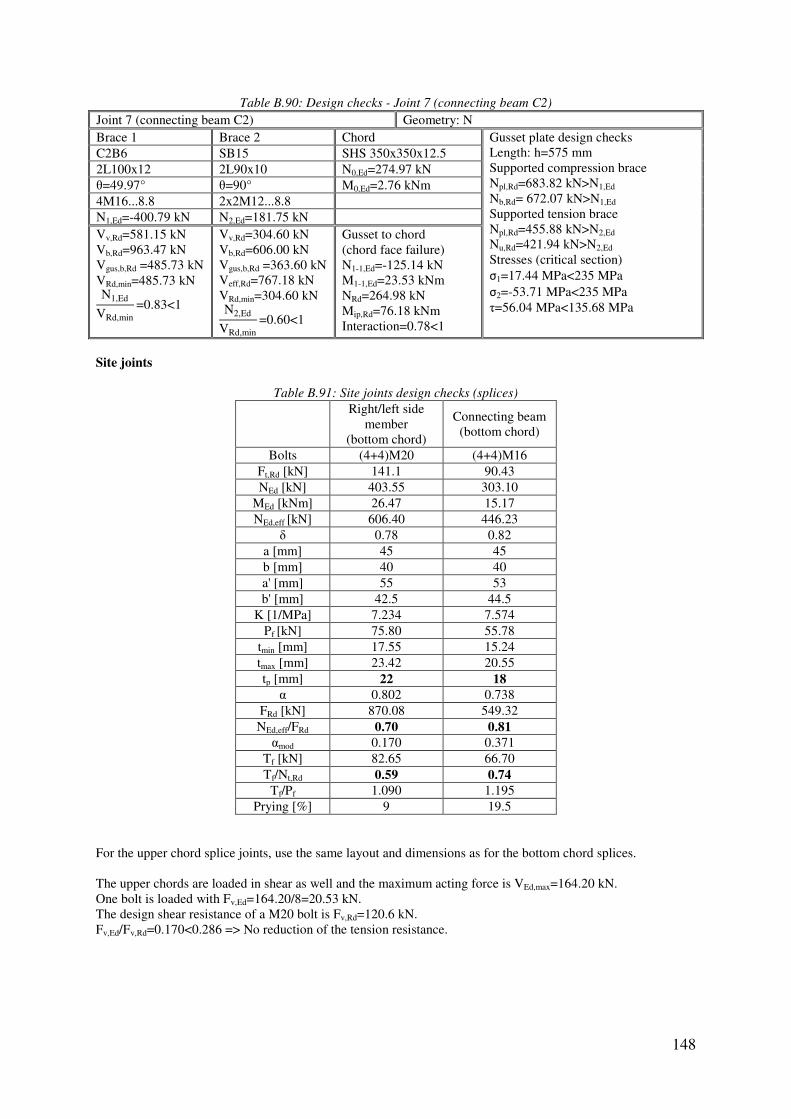
148
Table B.90: Design checks - Joint 7 (connecting beam C2)
Joint 7 (connecting beam C2) Geometry: N Brace 1 Brace 2 Chord Gusset plate design checks
Length: h=575 mm Supported compression brace Npl,Rd=683.82 kN>N1,Ed Nb,Rd= 672.07 kN>N1,Ed Supported tension brace Npl,Rd=455.88 kN>N2,Ed Nu,Rd=421.94 kN>N2,Ed Stresses (critical section) σ1=17.44 MPa<235 MPa σ2=-53.71 MPa<235 MPa τ=56.04 MPa<135.68 MPa
C2B6 SB15 SHS 350x350x12.5
2L100x12 2L90x10 N0,Ed=274.97 kN θ=49.97° θ=90° M0,Ed=2.76 kNm 4M16...8.8 2x2M12...8.8 N1,Ed=-400.79 kN N2,Ed=181.75 kN Vv,Rd=581.15 kN Vb,Rd=963.47 kN Vgus,b,Rd =485.73 kN VRd,min=485.73 kN N1,Ed
VRd,min=0.83<1
Vv,Rd=304.60 kN Vb,Rd=606.00 kN Vgus,b,Rd =363.60 kN Veff,Rd=767.18 kN VRd,min=304.60 kN N2,Ed
VRd,min=0.60<1
Gusset to chord (chord face failure) N1-1,Ed=-125.14 kN M1-1,Ed=23.53 kNm NRd=264.98 kN Mip,Rd=76.18 kNm Interaction=0.78<1
Site joints
Table B.91: Site joints design checks (splices)
Right/left side
member (bottom chord)
Connecting beam (bottom chord)
Bolts (4+4)M20 (4+4)M16 Ft,Rd [kN] 141.1 90.43 NEd [kN] 403.55 303.10
MEd [kNm] 26.47 15.17 NEd,eff [kN] 606.40 446.23
δ 0.78 0.82 a [mm] 45 45 b [mm] 40 40 a' [mm] 55 53 b' [mm] 42.5 44.5
K [1/MPa] 7.234 7.574 Pf [kN] 75.80 55.78
tmin [mm] 17.55 15.24 tmax [mm] 23.42 20.55 tp [mm] 22 18
α 0.802 0.738 FRd [kN] 870.08 549.32 NEd,eff/FRd 0.70 0.81
αmod 0.170 0.371 Tf [kN] 82.65 66.70 Tf/Nt,Rd 0.59 0.74
Tf/Pf 1.090 1.195 Prying [%] 9 19.5
For the upper chord splice joints, use the same layout and dimensions as for the bottom chord splices. The upper chords are loaded in shear as well and the maximum acting force is VEd,max=164.20 kN. One bolt is loaded with Fv,Ed=164.20/8=20.53 kN. The design shear resistance of a M20 bolt is Fv,Rd=120.6 kN. Fv,Ed/Fv,Rd=0.170<0.286 => No reduction of the tension resistance.

149
Table B.92: Weight (right/left side member-braces)
Member Single/ double config.
Cross-section Length [mm]
Unit weight [kg/m]
Total weight
[kg] SM1 2 L 90x90x10 1090 13.4 29.21 SM2 1 L 100x100x12 1374 17.8 24.46 SM3 2 L 100x100x12 1371 17.8 48.81 SM4 2 L 90x90x10 1090 13.4 29.21 SM5 2 L 100x100x12 1249 17.8 44.46 SM6 2 L 100x100x12 1249 17.8 44.46 SM7 2 L 90x90x10 1256 13.4 33.66 SM8 2 L 90x90x10 1256 13.4 33.66 SM9 2 L 90x90x10 1256 13.4 33.66
SM10 2 L 90x90x10 1256 13.4 33.66 SM11 2 L 130x130x12 1228 23.6 57.96 SM12 2 L 90x90x10 1090 13.4 29.21 SM13 2 L 130x130x12 1253 23.6 59.14 SM14 2 L 90x90x10 960 13.4 25.73
Σ 527.30 2·Σ 1054.61
Table B.93: Weight (right/left supporting beam-braces)
Member Single/ double config.
Cross-section Length [mm]
Unit weight [kg/m]
Total weight
[kg] SB1 2 L 90x90x10 1090 13.4 29.21 SB2 1 L 100x100x12 1335 17.8 23.76 SB3 2 L 90x90x10 1060 13.4 28.41 SB4 2 L 90x90x10 1335 13.4 35.78 SB5 2 L 90x90x10 1090 13.4 29.21 SB6 2 L 90x90x10 1255 13.4 33.63 SB7 1 L 100x100x12 1256 17.8 22.36 SB8 1 L 100x100x12 1256 17.8 22.36 SB9 1 L 100x100x12 1256 17.8 22.36
SB10 1 L 100x100x12 1256 17.8 22.36 SB11 1 L 100x100x12 1256 17.8 22.36 SB12 1 L 100x100x12 1256 17.8 22.36 SB13 2 L 90x90x10 990 13.4 26.53 SB14 2 L 130x130x12 1253 23.6 59.14 SB15 2 L 90x90x10 960 13.4 25.73 SB16 2 L 130x130x12 1366 23.6 64.48 SB17 2 L 90x90x10 1060 13.4 28.41
Σ 518.43 2·Σ 1036.87
Table B.94: Weight (connecting beam C1-braces)
Member Single/ double config.
Cross-section Length [mm]
Unit weight [kg/m]
Total weight
[kg] C1B1 2 L 100x100x12 1496 17.8 53.26 C1B2 2 L 100x100x12 1496 17.8 53.26 C1B3 2 L 90x90x10 1586 13.4 42.50 C1B4 2 L 90x90x10 1586 13.4 42.50 C1B5 2 L 100x100x12 1368 17.8 48.70 C1B6 2 L 100x100x12 1368 17.8 48.70
Σ 288.93

150
Table B.95: Weight (connecting beam C2-braces)
Member Single/ double config.
Cross-section Length [mm]
Unit weight [kg/m]
Total weight
[kg] C2B1 2 L 100x100x12 1496 17.8 53.26 C2B2 2 L 100x100x12 1496 17.8 53.26 C2B3 2 L 90x90x10 1586 13.4 42.50 C2B4 2 L 90x90x10 1586 13.4 42.50 C2B5 2 L 100x100x12 1368 17.8 48.70 C2B6 2 L 100x100x12 1368 17.8 48.70
Σ 288.93
Table B.96: Weight (chords)
Member Cross-section Length [mm]
Unit weight [kg/m]
Quantity Total
weight [kg]
Right side member SHS 350x350x12.5 9933 127 2 2522.98 Left side member SHS 350x350x12.5 9933 127 2 2522.98
Right supporting beam SHS 350x350x12.5 12000 127 2 3048.00 Left supporting beam SHS 350x350x12.5 12000 127 2 3048.00
Connecting beam SHS 350x350x12.5 8650 127 4 4394.20
Σ 15536.16
Table B.97: Weight (brackets)
Member Cross-section Length [mm]
Unit weight [kg/m]
Quantity Total
weight [kg]
Vertical HEB 360 4360 142 4 2476.48 Diagonal-left HEB 360 3134 142 2 890.06
Diagonal-right HEB 360 3518 142 2 999.11 Horizontal1-left HEA 800 3020 224 2 1352.96
Horizontal1-right HEA 800 3580 224 2 1603.84 Horizontal2-left 2L 90x90x10 1645 26.8 2 88.17
Horizontal2-right 2L 90x90x10 2208 26.8 2 118.35 Longitudinal IPE 550 2535 106 2 537.42
Σ 8066.39

