optical tweezers optical trap laser...
TRANSCRIPT
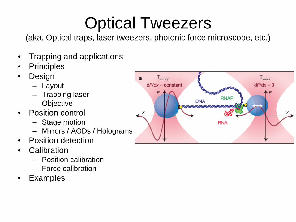
Optical Tweezers (aka. Optical traps, laser tweezers, photonic force microscope, etc.)
• Trapping and applications • Principles • Design
– Layout – Trapping laser – Objective
• Position control – Stage motion – Mirrors / AODs / Holograms
• Position detection • Calibration
– Position calibration – Force calibration
• Examples
What are Optical Tweezers(OT) ?
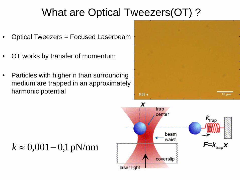
pN/nm 1,0001,0 −≈k
• Optical Tweezers = Focused Laserbeam
• OT works by transfer of momentum
• Particles with higher n than surrounding medium are trapped in an approximately harmonic potential
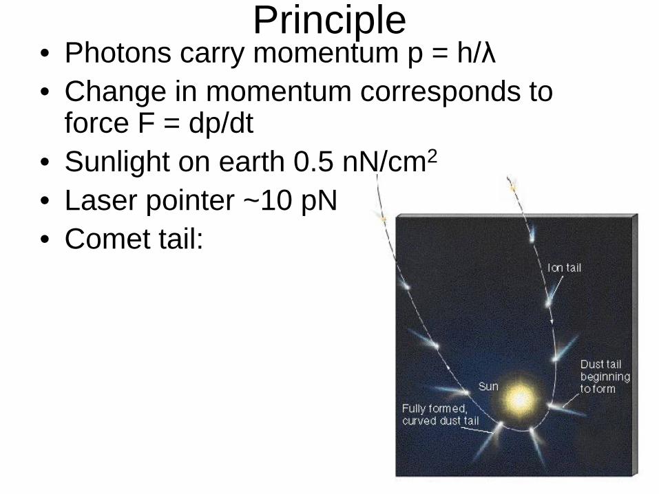
Principle • Photons carry momentum p = h/λ • Change in momentum corresponds to
force F = dp/dt • Sunlight on earth 0.5 nN/cm2
• Laser pointer ~10 pN • Comet tail:

History • Arthur Ashkin at Bell labs (Steve Chu nobel prize in 1997) • Theory 1970 (PRL 1970 24), Experiment in 1986 (Optics letters 11
1986) • 3D optical spring • Trap objects of 10 nm to 10 um

Length scales
10 m-10 10 m-9 10 m-8 10 m-7 10 m-6 10 m-5
Biological length scales
DNA base pair0.3 nm
DNA helicalpitch
KinesinStep
MyosinStep
rpoBgene
Phagegenome
10 m-10 10 m-9 10 m-8 10 m-7 10 m-6 10 m-5
Trapped particles
Hydrogen atom ATPPhagesRibosome
Light MicroscopyResolution limit Bacterium Red Blood
Cell

Time and force scales
10 s-12
0.1
10 s-9
1
10 s-6
10
10 s-3
100
10 s0
1000
10 s3
10000
Time
Force (pN)
protein domainmotions
Weight of 3umbead
Myosin Vstall
Kinesinstall
RNAPstall
Phagepackagingmotor stall
DNA BStransition
antibodyantigeninteraction
covalentbond
DNAHelixunwinding
Enzymaticreactions Protein
synthesiscelldivision
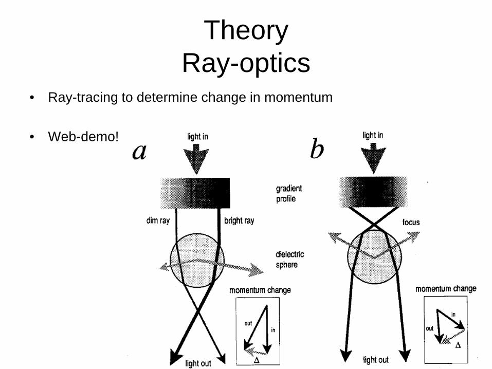
Theory Ray-optics
• Ray-tracing to determine change in momentum
• Web-demo!
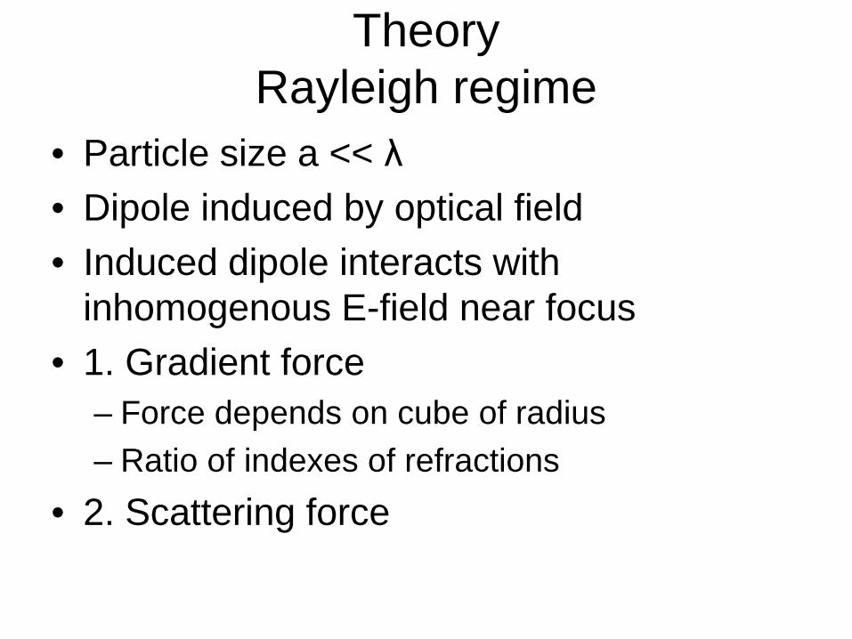
Theory Rayleigh regime
• Particle size a << λ • Dipole induced by optical field • Induced dipole interacts with
inhomogenous E-field near focus • 1. Gradient force
– Force depends on cube of radius – Ratio of indexes of refractions
• 2. Scattering force
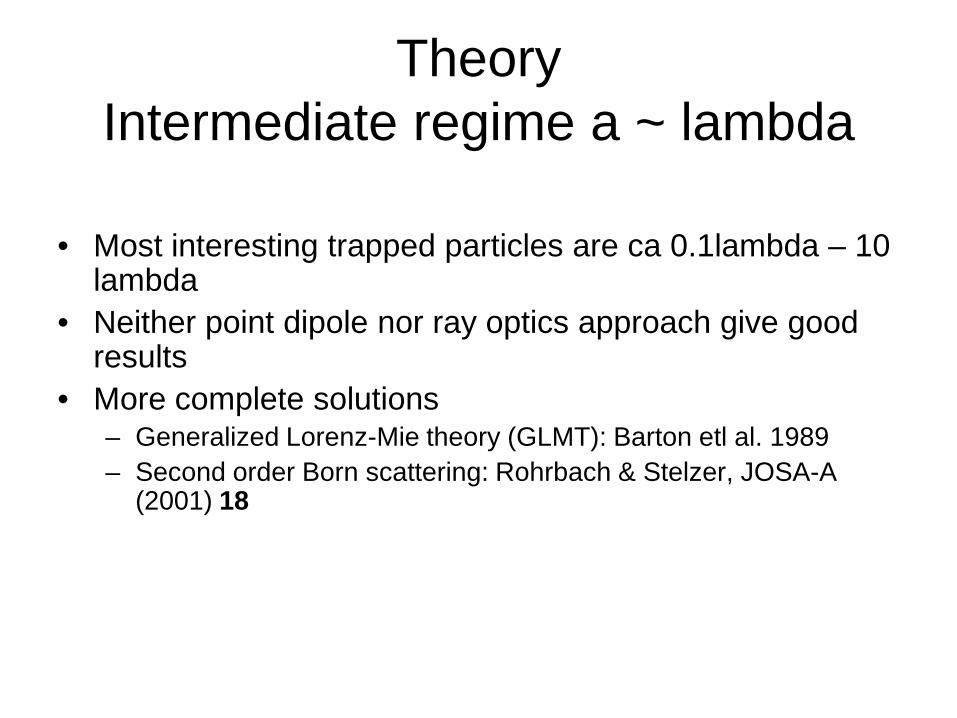
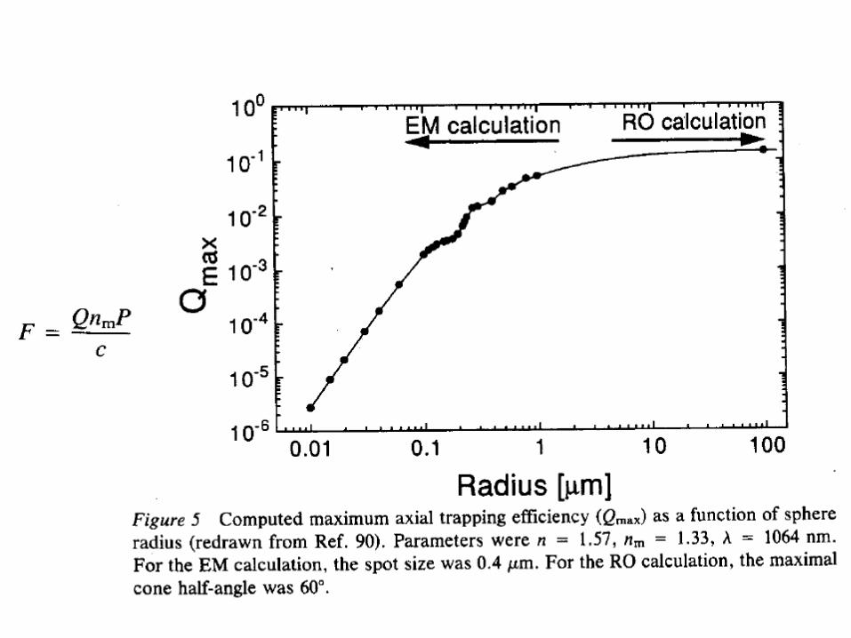
Theory Intermediate regime a ~ lambda
• Most interesting trapped particles are ca 0.1lambda – 10 lambda
• Neither point dipole nor ray optics approach give good results
• More complete solutions – Generalized Lorenz-Mie theory (GLMT): Barton etl al. 1989 – Second order Born scattering: Rohrbach & Stelzer, JOSA-A
(2001) 18
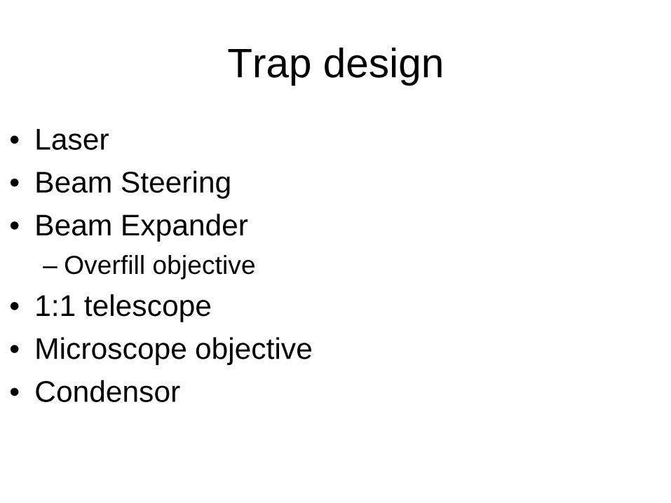
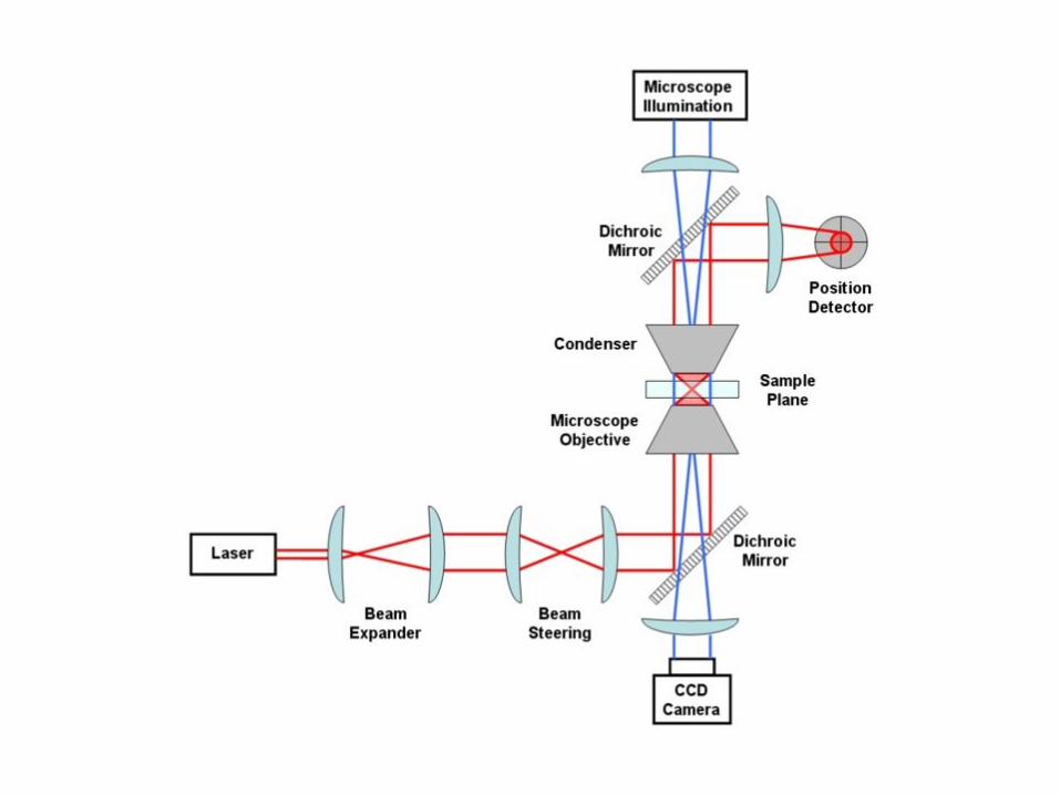
Trap design
• Laser • Beam Steering • Beam Expander
– Overfill objective • 1:1 telescope • Microscope objective • Condensor
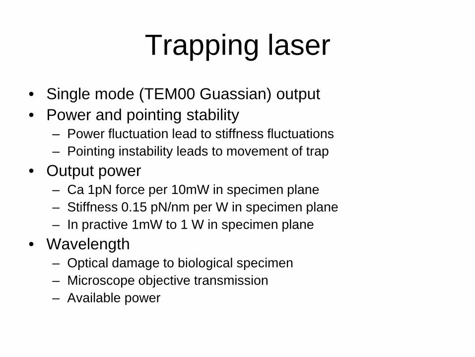
Trapping laser • Single mode (TEM00 Guassian) output • Power and pointing stability
– Power fluctuation lead to stiffness fluctuations – Pointing instability leads to movement of trap
• Output power – Ca 1pN force per 10mW in specimen plane – Stiffness 0.15 pN/nm per W in specimen plane – In practive 1mW to 1 W in specimen plane
• Wavelength – Optical damage to biological specimen – Microscope objective transmission – Available power

Optical damate • Biological specimens are relatively transparent in the near infrared (750 –
1200 nm) • Damage minimum 830 and 970 nm

3D trap positioning
• Move laser focus by moving first lens in telescope
• Beam rotates around back-aperture, which corresponds to translation of focus point
• Move lens in axial direction -> change focus position along optical axis
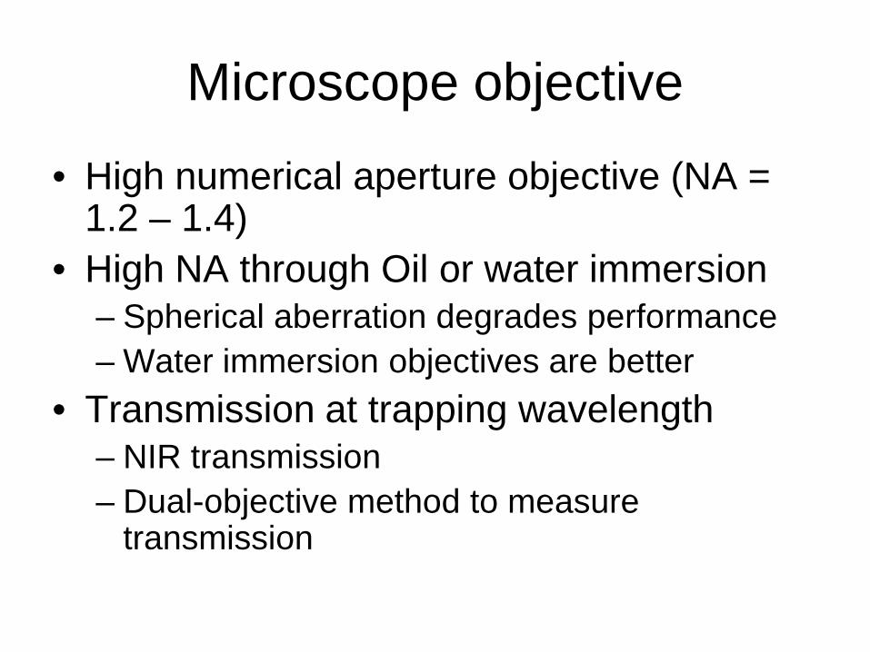
Microscope objective
• High numerical aperture objective (NA = 1.2 – 1.4)
• High NA through Oil or water immersion – Spherical aberration degrades performance – Water immersion objectives are better
• Transmission at trapping wavelength – NIR transmission – Dual-objective method to measure
transmission
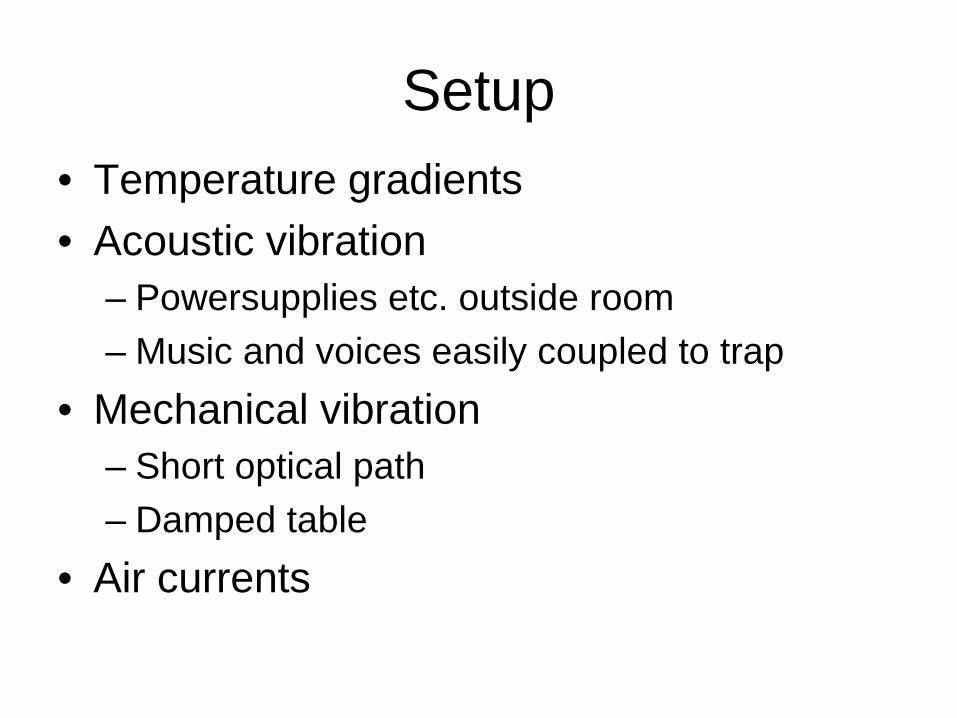
Setup • Temperature gradients • Acoustic vibration
– Powersupplies etc. outside room – Music and voices easily coupled to trap
• Mechanical vibration – Short optical path – Damped table
• Air currents
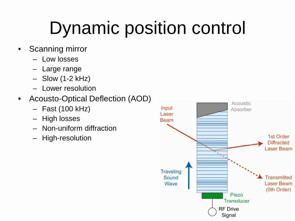
Dynamic position control • Scanning mirror
– Low losses – Large range – Slow (1-2 kHz) – Lower resolution
• Acousto-Optical Deflection (AOD) – Fast (100 kHz) – High losses – Non-uniform diffraction – High-resolution
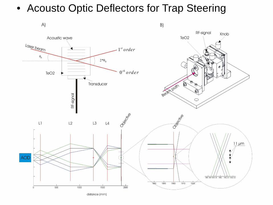
• Acousto Optic Deflectors for Trap Steering
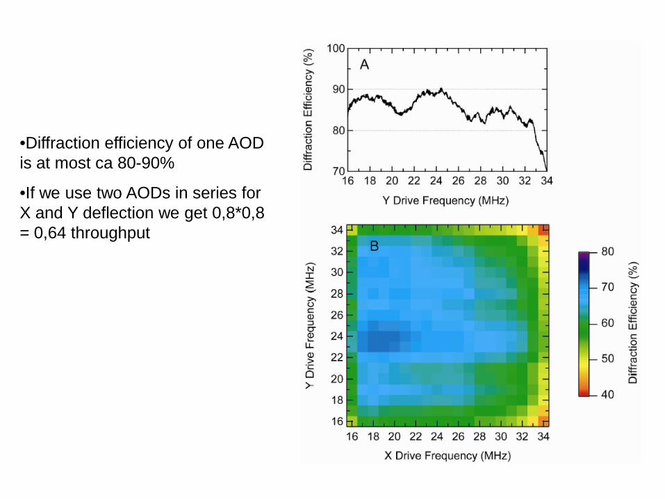
•Diffraction efficiency of one AOD is at most ca 80-90%
•If we use two AODs in series for X and Y deflection we get 0,8*0,8 = 0,64 throughput
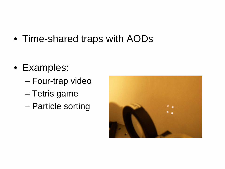
• Time-shared traps with AODs
• Examples: – Four-trap video – Tetris game – Particle sorting

Holographic Optical Tweezers
Example video!
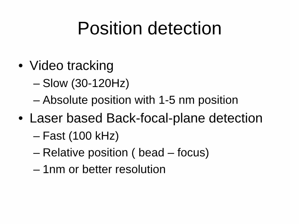
Position detection
• Video tracking – Slow (30-120Hz) – Absolute position with 1-5 nm position
• Laser based Back-focal-plane detection – Fast (100 kHz) – Relative position ( bead – focus) – 1nm or better resolution
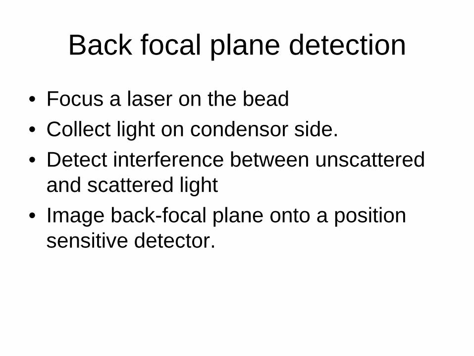
Back focal plane detection
• Focus a laser on the bead • Collect light on condensor side. • Detect interference between unscattered
and scattered light • Image back-focal plane onto a position
sensitive detector.
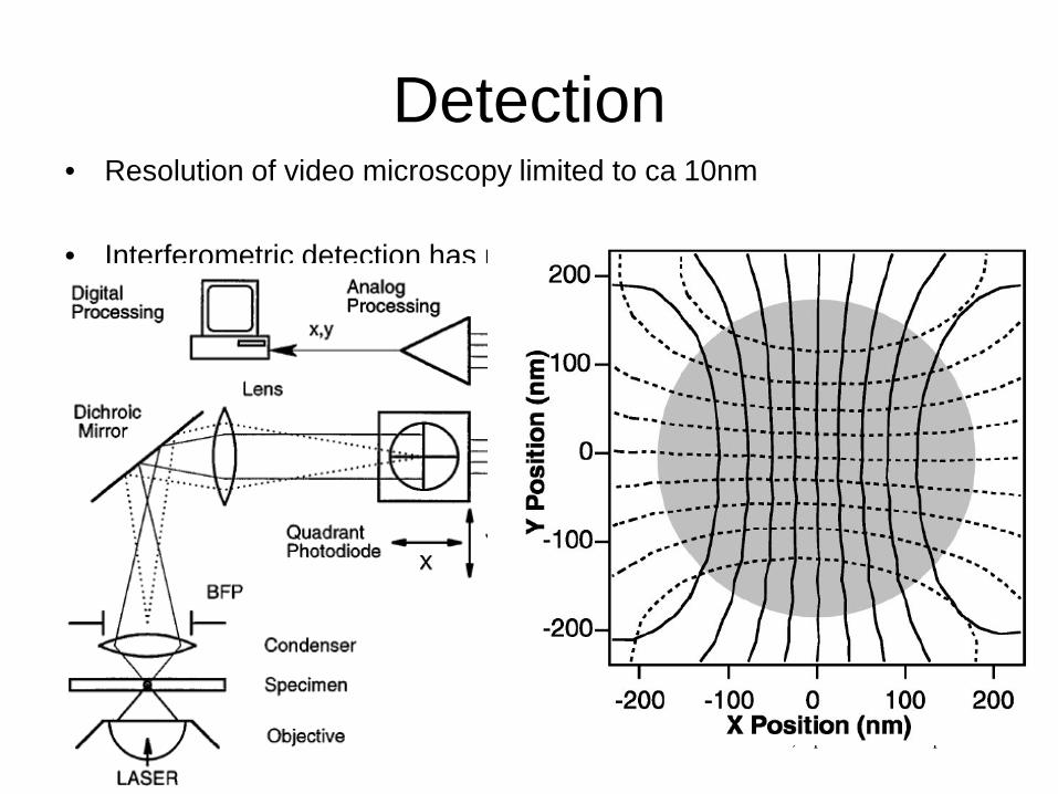
Detection • Resolution of video microscopy limited to ca 10nm
• Interferometric detection has much better resolution:
Gittes and Schmidt, Opt.Lett. Vol23no p7-9
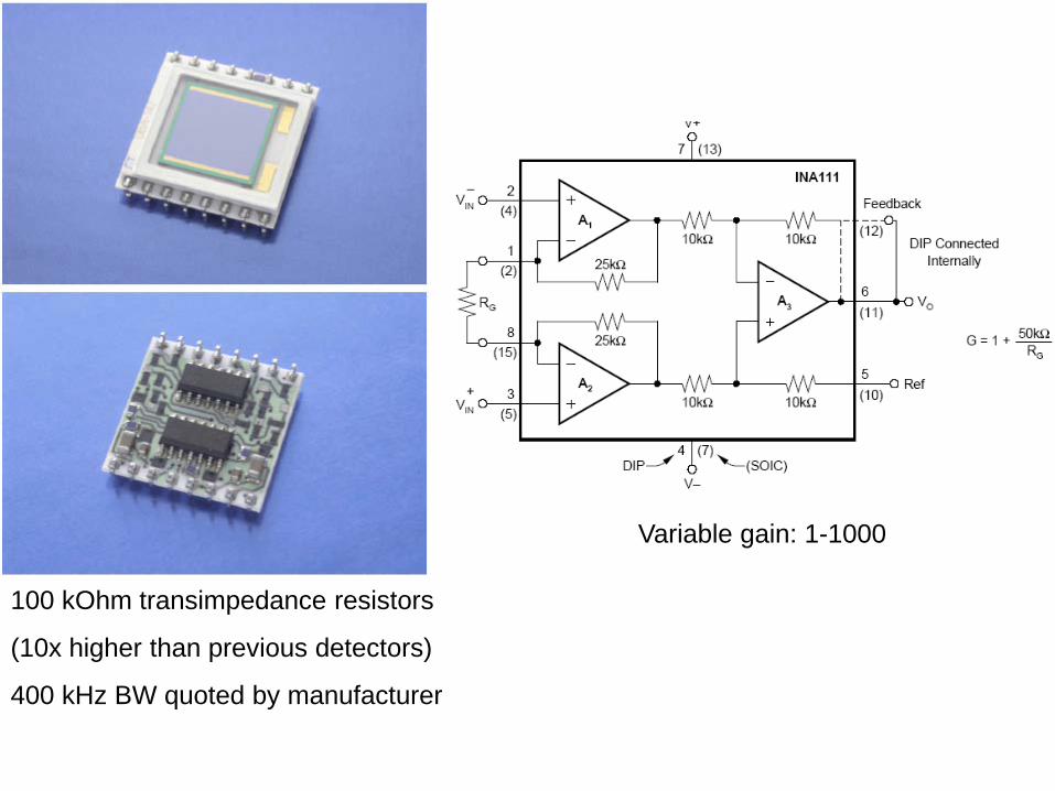
100 kOhm transimpedance resistors
(10x higher than previous detectors)
400 kHz BW quoted by manufacturer
Variable gain: 1-1000

Optical setup
1064ISO HWP
SH
SH1
OBJ
L
L
L
D3
HWP
PBS
M M
L
PBS
QPD
L L
Y X
AOD
LAMP
TL
CCD
M
M
L
632BFP
PZT
Calibration Position Calibration
• Position – Stage micrometer – Calibrated piezoelectric stage
• Move bead through detection range – Scan bead with PZT stage – Trap a bead and move it with AODs or mirrors
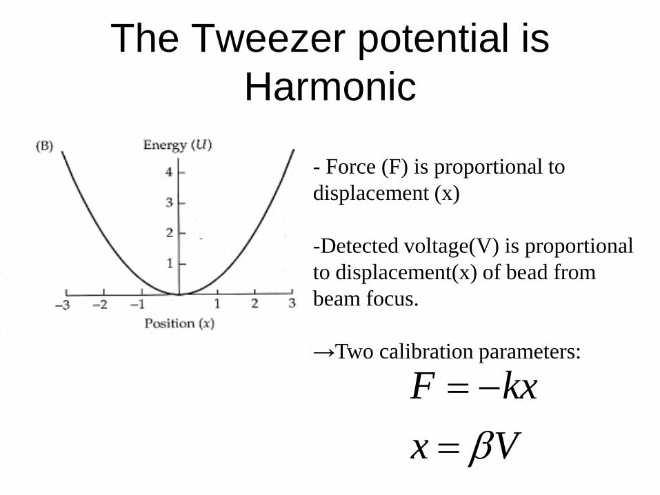
The Tweezer potential is Harmonic
- Force (F) is proportional to displacement (x) -Detected voltage(V) is proportional to displacement(x) of bead from beam focus. →Two calibration parameters:
VxkxF
β=−=

Calibration: Theoretical Power Spectrum
• Eq. Of motion for a Brownian particle in a harmonic potential:
force thermalrandomstiffness trap
drag Stokes6)(
==
===+
F(t)k
rtFkxx
ηπγγ
frequencycorner 2
)(2)(
:SpectrumPower gives ansformFourier tr
0
220
3
==
+=
πγ
γπkf
ffTkfS B
xx
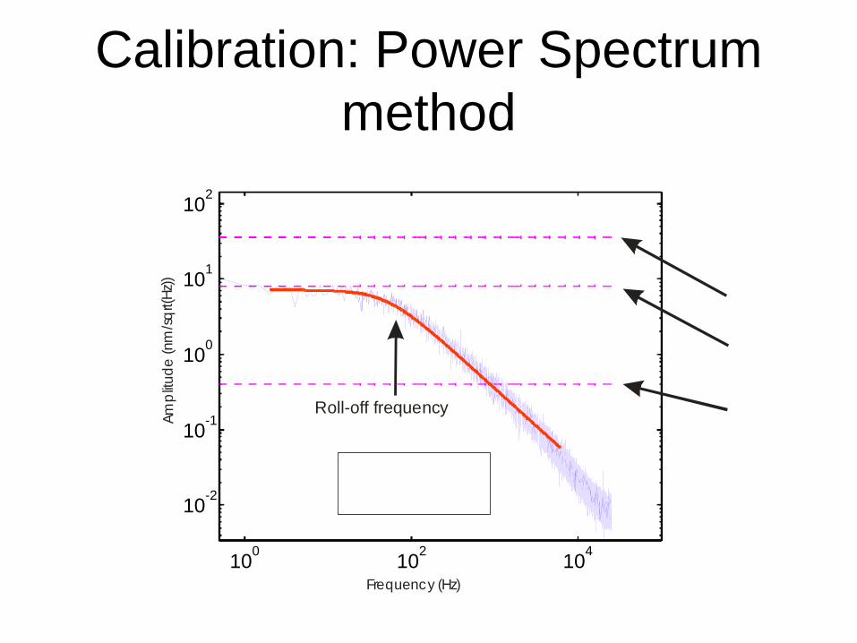
Calibration: Power Spectrum method
100 102 104
10-2
10-1
100
101
102
Frequency (Hz)
Ampl
itude
(nm
/sqrt(
Hz))
Roll-off frequency
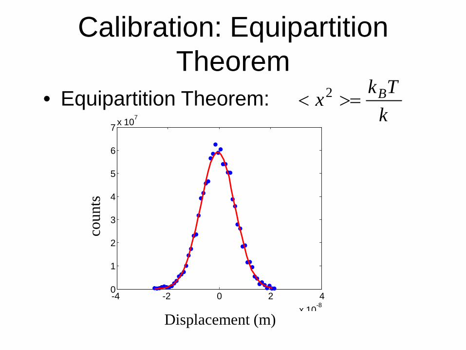
Calibration: Equipartition Theorem
kTkx B>=< 2• Equipartition Theorem:
-4 -2 0 2 4x 10⁻⁸
0
1
2
3
4
5
6
7 x 10⁷
Displacement (m)
coun
ts

Force calibration problems • Detection bandwidth • Unintended signal filtering • Anti-aliasing • Drag coefficient (Faxens law)
– Stokes law OK only when we are infinitely far away from surfaces
Force calibration, drag-force • Drag-force method
– Move stage or create flow to push bead out of trap
– Triangle-waveform stage motion – Check previous calibration, check for
nonlinearity – Proximity to surfaces is a problem -> Faxens
law instead of Stokes law
Optical Tweezers in biology
• First success in biology: studying kinesin, myosin (conventional molecular motors)
• Nucleic acid enzymes – RNAP (Block lab)
• Trapping whole cells (Goksör, Enger, Hanstorp)
• Lipid membrane manipulation PRL: force barriers for membrane tube formation