operator instruction manual - jupidex
TRANSCRIPT
McHale F5500F5500F5500F5500 1
McHale F5500F5500F5500F5500 Round Baler Operators Instruction Manual CLT00403_0
Operator Instruction Manual
ENGINEERING
F5500 F5500 F5500 F5500 Baler
McHale Engineering Castlebar Road, Ballinrobe
Co. Mayo, Ireland.
Tel: +353 94 9520300 Fax: +353 94 9520356
Email: [email protected] Web: www.mchale.net
0

McHale F5500F5500F5500F5500 2
McHale F5500F5500F5500F5500 Round Baler Operators Instruction Manual CLT00403_0
McHale F5500F5500F5500F5500 3
McHale F5500F5500F5500F5500 Round Baler Operators Instruction Manual CLT00403_0
1. Introduction The McHale F5500F5500F5500F5500 round baler is a completely new product. The design has been carried out on the basis of long term constant research and development in the field of round bale wrappers and round balers. Given proper care and attention, the McHale F5500F5500F5500F5500 will provide years of reliable and dependable performance. However it is also important that everybody who operates this machine reads and understands this manual before operating the machine. If any of the instructions appear unclear do not hesitate to contact your McHale dealer. It is vital to replace defective parts of the machine immediately and to use only genuine McHale spare parts, as these are designed and manufactured to the same specification as the original machine. These may be obtained through your McHale dealer. Description of a fully trained operator: The McHale F5500F5500F5500F5500 will require a fully trained operator. This is someone who has read and fully understood all of the contents of this instruction manual. They must be aware of all safety instructions, of all functions and controls, both hydraulic and electrical. The operator is solely responsible for the safe use and maintenance of the machine in accordance with this manual. It is highly recommended that training be sought from your local dealer. The operator must be constantly aware of their surroundings and should always think of safety first. The machine is only to be used for it’s designated purpose as is outlined . Note: The above description is a guideline only, and as a rule, it is highly recommended to get acquainted slowly at first with any new machinery. Take the time to both learn and understand all the features of the machine. Proficiency will increase as more experience is obtained. It is important to quote the machine serial number when ordering spare parts or requesting technical assistance. Space is provided below to record the machine details:
If you require further copies of this instruction manual please quote part number: CLT00403 *
* Manuals are serial number specific so please quote the relevant machine serial
number
Due to a policy of continuous product development and improvement, McHale Engineering reserves the right to alter machine specifications without prior notice. Please note that all
specifications marked with an in this manual relate to certain models or optional equipment. Also these specifications may not be available in all countries.
Serial number: Year of manufacture: Date of delivery:
McHale F5500F5500F5500F5500 4
McHale F5500F5500F5500F5500 Round Baler Operators Instruction Manual CLT00403_0
2. Table of Contents
Section Page
1 Introduction 03
2 Table of Contents 04
3 Getting Familiar with the McHale F5500 08
3.1 Designated Use of the Machine 08
4 General Safety
4.1 Be aware of all Safety Information 10
4.2 Follow all Safety Instructions 10
4.3 Store all items carefully 10
4.4 Protective Clothing 10
4.5 In Case of Emergencies 11
4.6 Stay Clear of Rotating Elements 11
4.7 Operating the McHale F5500 Safely 11
4.8 In the Event of a Fire 11
4.9 General Safety Warnings 12
5 Specific Safety Warnings
5.1 Electronic Safety Warnings 14
5.2 Hydraulic Safety Warnings 14
5.3 Noise Level 15
5.4 Fire Precautions 15
5.5 Special Safety Devices/ Instructions 15
5.6 Safety/ Instruction Decal Locations 16
5.7 Description of Safety Warnings and Instructions 18
5.8 Descriptions of the Serial Number Plate 24
5.9 Machine Lifting Guidelines 25
McHale F5500F5500F5500F5500 5
McHale F5500F5500F5500F5500 Round Baler Operators Instruction Manual CLT00403_0
Section Page
6 Tractor Requirements and Preparations
6.1 Tractor Requirements 26
6.2 Control Box Installation 26
6.3 Attaching to Drawbar 27
6.4 Attaching the F5500 to the PTO (540 rpm) 27
6.5 Lighting System 27
6.6 Attaching the Hydraulic Hosing to the Tractor 28
6.7 Connecting the Control Box 28
7 Baler Requirements and Preparation
7.1 Net Requirements 29
7.2 Care of the Net Roll 29
7.3 Care of the Net Wrapping System 29
7.4 Loading and Operating the Netter System 30
7.5 Net Length Adjustment Setting - Net Tension Bar Setting 32
7.6 Adjusting the Net Tension 33
7.7 Chopper Unit Knife Removal, Installation & Storage 35
7-8 Automatic Lubrication System 39
7-9 Gearbox Oil 42
7.10 Tyre Inflation Pressures 42
7.11 Drawbar and PTO Shaft Stand Functions 44
7.12 Drawbar Adjustment 46
7.13 PTO Shaft Adjustments and Maintenance 47
8 Control Box Overview And Features
8.1 Control Box Overview and Features 48
8.2 Control Box Operation 50
8.3 Control Unit Menu 54
8.4 Warning Screens 57
9 Road Traffic Safety and Operation
9.1 Before Travelling on any Public Road 59
9.2 Road Transportation 60
McHale F5500F5500F5500F5500 6
McHale F5500F5500F5500F5500 Round Baler Operators Instruction Manual CLT00403_0
Section Page
10 Baler Field Operations and Baler Adjustment
10.1 Break in Period 61
10.2 Swath Preparation 61
10.3 Pick-up Reel Height Adjustment 62
10.4 Crop Guard Adjustment 62
10.5 Unblocking System 63
10.6 Chopping System 64
10.7 Selectable Knives 64
10.8 Knife Pressure Monitoring 65
10.9 Net Wrap System 66
10.10 Bale Density Gauge 67
10.11 Setting Chamber Pre-Charge Pressure 67
10.12 Bale Size Adjustment 68
10.13 Tail gate Safety Lock 69
10.14 Adjusting Pick up Float Springs 70
11 Accessories and Optional Equipment
11.1 Accessory and Optional Equipment Available 74
11.2 Wheel Chocks 74
11.3 Drawbar Hitch Options 74
11.4 Tyre Options 74
11.5 Stand Options 75
11.6 Brake Options 76
12 Machine Maintenance
12.1 Maintenance Intervals 78
12.2 Tightening Torque Values 80
13 Storage
13.1 End of Season Storage 81
13.2 Start of Season Preparation 81
10.15 Chain Adjustments 71
11.7 Heavy Duty PTO Shaft 76
11.8 Selectable Knives 77
11.9 Crop Roller 77
McHale F5500F5500F5500F5500 7
McHale F5500F5500F5500F5500 Round Baler Operators Instruction Manual CLT00403_0
Section Page
14 Technical Specifications
14.1 General Dimensions/ Specifications 82
14.2 Tractor Attachments 82
14.3 Machine Specifications 82
14.4 Tyre Specifications 82
14.5 Declaration of Conformity 83
14.6 Change of Ownership Pre-Checks 84
15 Trouble Shooting
15.1 Trouble Shooting Overview 85
15.2 Machine using Higher than expected HP when Chopping 85
15.3 Pick-up Slip Clutch going off Easily 85
15.4 P.T.O. Slip Cutch going off Easily 86
15.5 Knives Not Remaining Up while Chopping 86
15.6 Knife Pressure Too Low or Dropping completely 86
15.7 Knife Pressure Too High 87
15.8 Chamber Losing Pressure 87
15.9 Issue with Bale Rotation/ Intake 87
15.10 Issues with Bale Quality/ Density 88
15.11 Net Not Feeding during an Automatic Cycle 88
15.12 Net Slipping on the Rubber Roller 89
15.13 Machine Won’t Cut the Net 89
15.14 Net Not Cut Correctly 89
15.15 Chopper Knives Won’t Move - Pick-up Moves 90
15.16 Drop Floor Won’t Move (Up or Down) - Pick-up Moves 90
15.17 Greaser Not Working 90
16 Limited Warranty 91

McHale F5500F5500F5500F5500 8
McHale F5500F5500F5500F5500 Round Baler Operators Instruction Manual CLT00403_0
3. Getting Familiar with the McHale F5500F5500F5500F5500 The McHale F5500F5500F5500F5500 is protected against many dangers to itself while being operated from the control box in both manual and automatic cycles. However, it is of utmost importance for the safety of the operator and for others, that the operator pay attention to all warnings and instructions given in this manual. In particular all safety devices, decals, guards and controls must be in place and in fully functioning condition. Never try to clear any malfunction when the tractor is switched on or the machine running. Keep the “danger zone” (An area around the machine detailed in section 4.9) free of all persons and animals at all times while the machine is in operation. This manual must be read and fully understood by anyone who will operate the machine.
3.1 Designated use of machine � The McHale F5500F5500F5500F5500 round baler is exclusively designed for normal use in
agricultural applications. The machine has been designed to pick up and compact cut crop from the ground, to produce bales of forage primarily for feeding livestock. This designation includes the movement of the machine, between fields by track or road, incidental to the round baler. The manufacturer will not be held responsible for any loss or damage resulting from machine applications other than those specified above. Any other use the machine may be put to, is entirely at the owners/operators risk.
� The designated use of the machine includes that the operating, maintenance and
repair instructions given by the manufacturer will be strictly fulfilled. � The designated use of the machine includes, that exclusively persons who
are familiar with it and instructed about the risks are entitled to operate, maintain and/or to repair the machine.
� The designated use of the machine includes that the relevant health and
safety requirements, that may be in force in the country of use will be strictly followed.
� The designated use of the machine includes that no other equipment or accessories other than released by the manufacturer are installed in the machine. The use of any other equipment or accessory is entirely at the owners/operators risk in such cases unauthorised modifications/ changes exclude any liability of the manufacturer there off.
By any alteration of safety equipment, the Declaration of conformity, as well as the CE-sign on the machine loses it’s validity.
McHale F5500F5500F5500F5500 9
McHale F5500F5500F5500F5500 Round Baler Operators Instruction Manual CLT00403_0
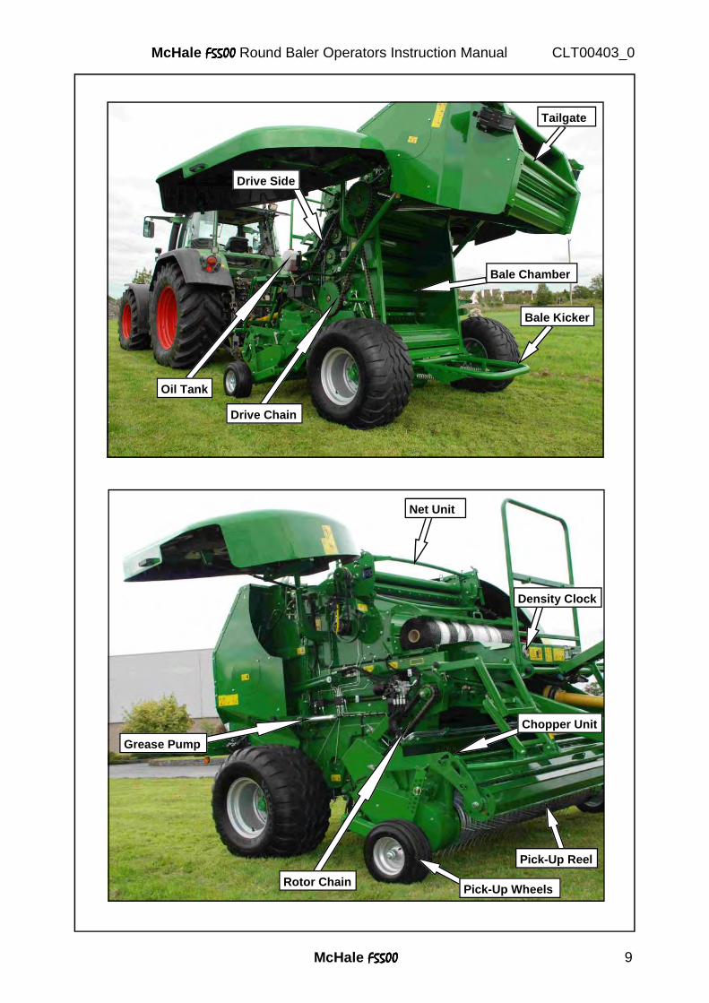
Tailgate
Drive Side
Oil Tank
Drive Chain
Bale Chamber
Bale Kicker
Net Unit
Density Clock
Chopper Unit
Pick-Up Reel
Rotor Chain
Grease Pump
Pick-Up Wheels
McHale F5500F5500F5500F5500 10
McHale F5500F5500F5500F5500 Round Baler Operators Instruction Manual CLT00403_0
4. General Safety
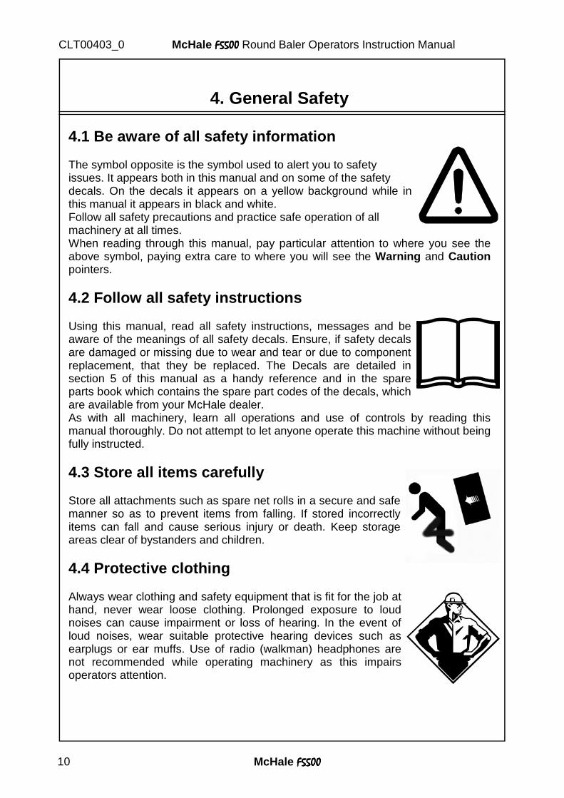
4.1 Be aware of all safety information The symbol opposite is the symbol used to alert you to safety issues. It appears both in this manual and on some of the safety decals. On the decals it appears on a yellow background while in this manual it appears in black and white. Follow all safety precautions and practice safe operation of all machinery at all times. When reading through this manual, pay particular attention to where you see the above symbol, paying extra care to where you will see the Warning and Caution pointers.
4.2 Follow all safety instructions Using this manual, read all safety instructions, messages and be aware of the meanings of all safety decals. Ensure, if safety decals are damaged or missing due to wear and tear or due to component replacement, that they be replaced. The Decals are detailed in section 5 of this manual as a handy reference and in the spare parts book which contains the spare part codes of the decals, which are available from your McHale dealer. As with all machinery, learn all operations and use of controls by reading this manual thoroughly. Do not attempt to let anyone operate this machine without being fully instructed.
4.3 Store all items carefully Store all attachments such as spare net rolls in a secure and safe manner so as to prevent items from falling. If stored incorrectly items can fall and cause serious injury or death. Keep storage areas clear of bystanders and children.
4.4 Protective clothing Always wear clothing and safety equipment that is fit for the job at hand, never wear loose clothing. Prolonged exposure to loud noises can cause impairment or loss of hearing. In the event of loud noises, wear suitable protective hearing devices such as earplugs or ear muffs. Use of radio (walkman) headphones are not recommended while operating machinery as this impairs operators attention.
McHale F5500F5500F5500F5500 11
McHale F5500F5500F5500F5500 Round Baler Operators Instruction Manual CLT00403_0
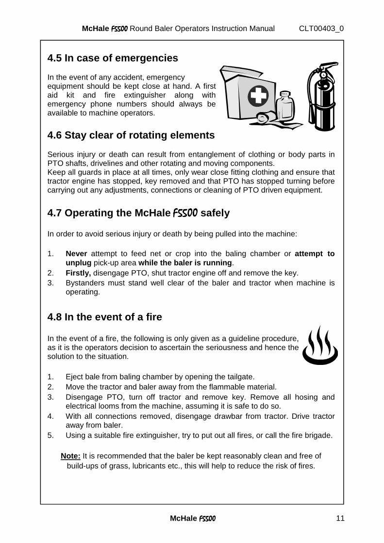
4.5 In case of emergencies In the event of any accident, emergency equipment should be kept close at hand. A first aid kit and fire extinguisher along with emergency phone numbers should always be available to machine operators.
4.6 Stay clear of rotating elements Serious injury or death can result from entanglement of clothing or body parts in PTO shafts, drivelines and other rotating and moving components. Keep all guards in place at all times, only wear close fitting clothing and ensure that tractor engine has stopped, key removed and that PTO has stopped turning before carrying out any adjustments, connections or cleaning of PTO driven equipment.
4.7 Operating the McHale F5500F5500F5500F5500 safely
In order to avoid serious injury or death by being pulled into the machine: 1. Never attempt to feed net or crop into the baling chamber or attempt to
unplug pick-up area while the baler is running . 2. Firstly, disengage PTO, shut tractor engine off and remove the key. 3. Bystanders must stand well clear of the baler and tractor when machine is
operating.
4.8 In the event of a fire In the event of a fire, the following is only given as a guideline procedure, as it is the operators decision to ascertain the seriousness and hence the solution to the situation. 1. Eject bale from baling chamber by opening the tailgate. 2. Move the tractor and baler away from the flammable material. 3. Disengage PTO, turn off tractor and remove key. Remove all hosing and
electrical looms from the machine, assuming it is safe to do so. 4. With all connections removed, disengage drawbar from tractor. Drive tractor
away from baler. 5. Using a suitable fire extinguisher, try to put out all fires, or call the fire brigade.
Note: It is recommended that the baler be kept reasonably clean and free of build-ups of grass, lubricants etc., this will help to reduce the risk of fires.
McHale F5500F5500F5500F5500 12
McHale F5500F5500F5500F5500 Round Baler Operators Instruction Manual CLT00403_0
4.9 General safety warnings � Read and understand this operator’s manual before using the machine. If any
of the instructions appear unclear do not hesitate to contact your McHale dealer.
� Only competent persons who have read and fully understood this manual are
qualified to operate this machine. The owner of this machine is obliged by law to ensure that every operator must understand all the functions, controls, working processes and safety warnings before operating the machine.
� All safety devices such as guards, protection parts and safety controls must
be in place and in fully functioning condition. It is forbidden to operate this machine with defective or incomplete safety devices.
���� All safety decals on the machine must be kept in good legible condition. If
they are not they must be replaced by genuine McHale decals from your McHale dealer (part numbers are available in this manual).
���� Before operating this machine the operator must ensure that all covers are
closed and all safety devices are in operating mode. � Before operating this machine the operator must ensure that the
manufacturer’s instructions for attaching and detaching the machine are followed. This includes the drawbar attachment, the electric and hydraulic lines, in particular the lighting and brake system.
���� Before operating this machine the operator must ensure that no persons or
animals are carried on the machine or are hidden under the machine (on the tractor persons are only allowed to sit on the relevant seats).
���� Before operating this machine the operator must ensure that there is no
person in the “danger zone” (in front of tractor, between tractor and round baler and a minimum of 10 m behind the machine).
Note: It is the operator’s responsibility to keep all people out of this area! In this area a person is subject to a risk to his/her own health or safety!” � While operating this machine on hilly or sloping ground the operator must
take extra precautions, in particular the “danger zone” is increased in such conditions as bales are more likely to roll away causing a potential risk.
McHale F5500F5500F5500F5500 13
McHale F5500F5500F5500F5500 Round Baler Operators Instruction Manual CLT00403_0
���� Before working on this machine, such as replacing net, clearing forage away
from any part of the machine or altering any setting, the operator must ensure that the tractor has definitely stopped moving, handbrake is applied, engine has stopped and ignition key is removed, PTO shaft is removed from PTO stub and electric power supply is disconnected. It is forbidden to open any safety guards or to carry out any work on the machine unless the above-specified precautions have been carried out.
���� Warning! If carrying out inspection during machine operation within the danger
zone (highly dangerous and not recommended! ), then there should be a trained and fully competent second person operating both the tractor and baler controls. If at any time the second operator loses sight of the inspector, turn off all tractor power immediately! Such inspection should only be carried out if all guards are fully in place, machine on level ground and a safe distance is maintained from any hazards on the machine e.g. pick-up region.
���� When conducting maintenance work tie long hair behind your head. Do not wear a necktie, necklace, scarf or loose clothing when you work near the machine or moving parts. If these items were to get caught, severe injury could result.
���� When conducting maintenance work always support machine properly
where possible always lower the attachment or implement to the ground before you work on the machine. If it is not possible to lower the machine or attachment to the ground, always securely support the machine or attachment. Do not work under a machine that is solely supported by a jack. Never support the machine with props that may break or crumble under continuous load.
� When conducting repair work, avoid heating near pressurised fluid lines as pressured lines can be accidentally damaged when heat goes beyond the immediate flame area.
���� Maintenance and repair work on this machine should always be carried out
in accordance with this manual. ���� Maintenance and repair work exceeding the content of this manual should
only be carried out by qualified persons or your McHale dealer. � Before travelling on public roads the owner of this machine is obliged by law
to ensure that every operator has got a valid driving licence and is familiar with the road traffic regulations relating to the country of use (see section 9).
� When parking both wheels of this machine have to be blocked using the
wheel chocks according to the road traffic regulations relating to the country of use.

McHale F5500F5500F5500F5500 14
McHale F5500F5500F5500F5500 Round Baler Operators Instruction Manual CLT00403_0
5. Specific Safety Warnings
5.1 Electronic safety warnings
���� This machine is equipped with electronic parts and components which comply to the EMC directive 2004/108/CE but still may be influenced by electromagnetic transmissions of other apparatus, such as welding machines, etc.
� Check electric cables regularly for signs of breakage or wear. If in doubt always replace.
5.2 Hydraulic safety warnings
� The maximum pressure in the hydraulic system of this machine should not exceed 210 bar.
� Always ensure system is not under pressure before working on the machine. Oil under pressure can penetrate the skin and cause injury. Beware of pipes under accumulator pressure, depressurise lines by unthreading connections extremely slowly.
� Hydraulically actuated devices, such as pick-up and cutting device must be blocked mechanically against movement, before working on the machine.
� If any hoses are removed or replaced ensure they are marked and re-installed to the correct position during re-assembly.
� Check hoses regularly for signs of leakage or wear. If in doubt always replace – the recommended maximum working time of hoses should not exceed 5 years. Only use exact specification, McHale genuine replacement parts.
� Do not work on hydraulic systems unless you are qualified to do so, this work should only be carried out by qualified persons or your McHale dealer.
McHale F5500F5500F5500F5500 15
McHale F5500F5500F5500F5500 Round Baler Operators Instruction Manual CLT00403_0
5.3 Noise level The European regulation 86/188/EEC directs employers and employees to control the noise level at work. The noise level at field work may differ according to the tractor, to the ground, to the crops and other environmental conditions. In normal conditions the noise level next to the drivers ear of the McHale F5500F5500F5500F5500 round baler does not exceed 70 dB (A) with the rear screen of the tractor cabin open. The common noise level of the machine and the tractor is primarily influenced by the tractor noise (radio is an additional noise source). It is recommended to operate this machine with closed cabin windows.
5.4 Fire precautions � Be aware that crops are easily flammable. � Do not smoke or make use of any open fire next to the machine. � A functioning fire extinguisher should always be available on the tractor. � The machine is to be kept cleaned of oil, grease, crops or any other flammable
material at all times. � Do not continue work with overheated parts, cables or pipes unless you have
identified and eliminated the reason for overheating.
5.5 Special safety devices / instructions � According to the European safety regulations the covers of this machine are
designed to be opened only by the aid of a special tool and to be closed without a tool. For unlocking the covers the locks should be turned slightly
anti-clockwise with a 13mm-spanner; for locking the covers push cover towards the chassis until the fasteners lock into place. It is forbidden to operate the machine without covers or with the covers open. The owner of this machine is obliged by law to ensure that all covers are installed on the machine and are in good functioning condition. � When maintenance or repair work has to be carried out on the open bale
chamber the tailgate lever valve must always be in the locked position and before the tail gate can be closed it has to be unlocked again. For further information, please see section 10.13.
� Before replacing the knives of the chopping system make sure that all knives
are in the upper position. Always use protective gloves when working on the chopping system.
� Caution should always be taken when feeding in the net roll or making any
adjustments to the netter configuration as the netter knife is extremely sharp!
McHale F5500F5500F5500F5500 16
McHale F5500F5500F5500F5500 Round Baler Operators Instruction Manual CLT00403_0
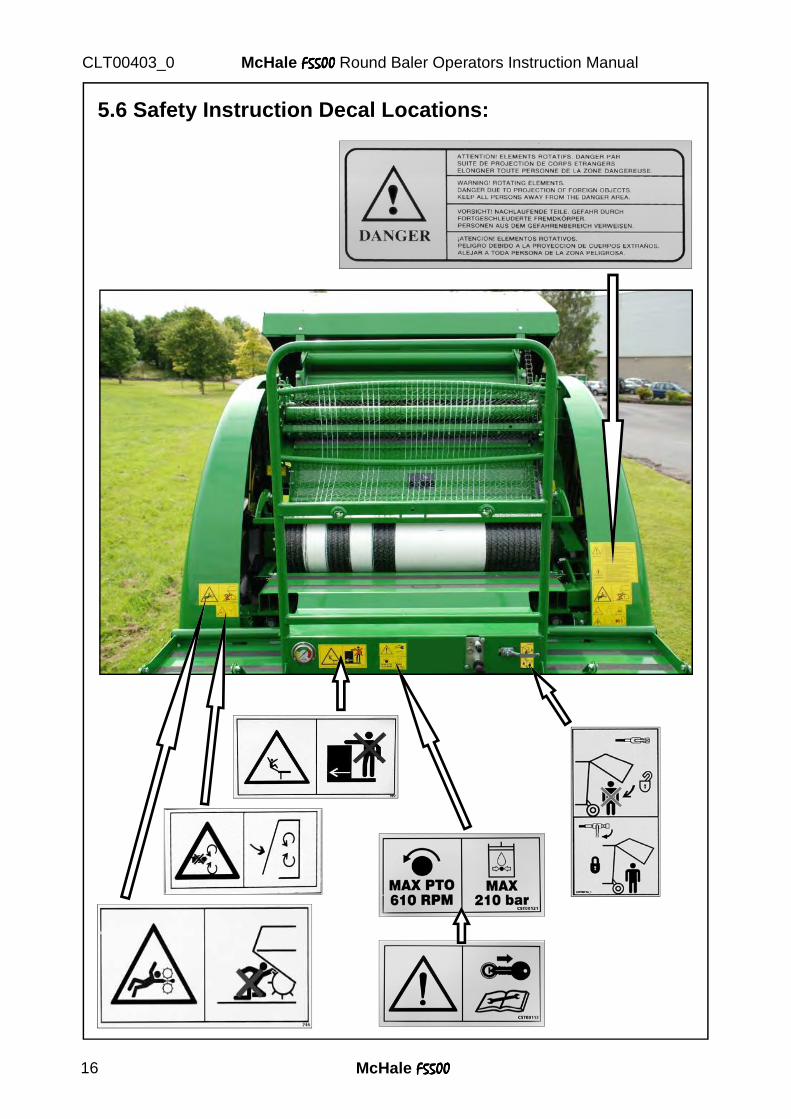
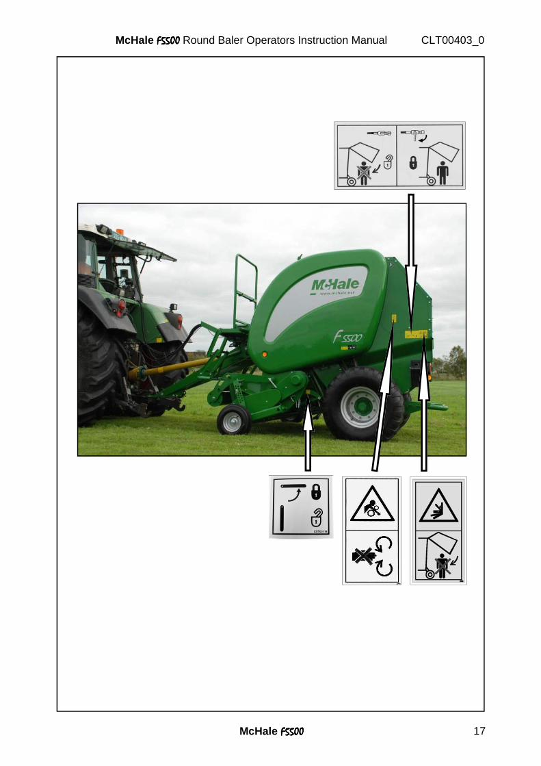
5.6 Safety Instruction Decal Locations:
McHale F5500F5500F5500F5500 17
McHale F5500F5500F5500F5500 Round Baler Operators Instruction Manual CLT00403_0
5500
McHale F5500F5500F5500F5500 18
McHale F5500F5500F5500F5500 Round Baler Operators Instruction Manual CLT00403_0
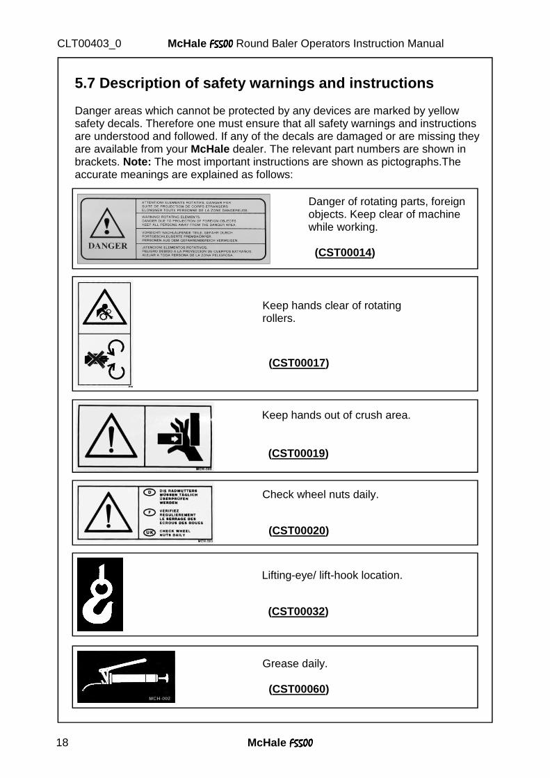
5.7 Description of safety warnings and instructions Danger areas which cannot be protected by any devices are marked by yellow safety decals. Therefore one must ensure that all safety warnings and instructions are understood and followed. If any of the decals are damaged or are missing they are available from your McHale dealer. The relevant part numbers are shown in brackets. Note: The most important instructions are shown as pictographs.The accurate meanings are explained as follows:
Danger of rotating parts, foreign objects. Keep clear of machine while working. (CST00014)
Keep hands out of crush area. (CST00019)
Lifting-eye/ lift-hook location. (CST00032)
Grease daily. (CST00060)
Check wheel nuts daily. (CST00020)
Keep hands clear of rotating rollers. (CST00017)
McHale F5500F5500F5500F5500 19
McHale F5500F5500F5500F5500 Round Baler Operators Instruction Manual CLT00403_0
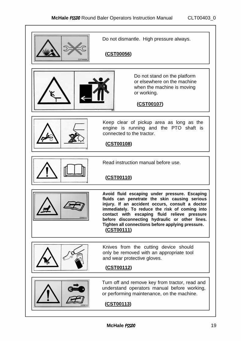
Do not dismantle. High pressure always. (CST00056)
Do not stand on the platform or elsewhere on the machine when the machine is moving or working. (CST00107)
Keep clear of pickup area as long as the engine is running and the PTO shaft is connected to the tractor. (CST00108)
Read instruction manual before use. (CST00110)
Turn off and remove key from tractor, read and understand operators manual before working, or performing maintenance, on the machine. (CST00113)
Knives from the cutting device should only be removed with an appropriate tool and wear protective gloves.
(CST00112)
Avoid fluid escaping under pressure. Escaping fluids can penetrate the skin causing serious injury. If an accident occurs, consult a doctor immediately. To reduce the risk of coming into contact with escaping fluid relieve pressure before disconnecting hydraulic or other lines. Tighten all connections before applying pressure. (CST00111)
McHale F5500F5500F5500F5500 20
McHale F5500F5500F5500F5500 Round Baler Operators Instruction Manual CLT00403_0
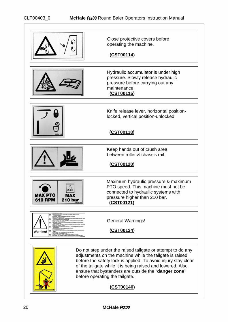
Close protective covers before operating the machine. (CST00114)
Knife release lever, horizontal position-locked, vertical position-unlocked. (CST00118)
Keep hands out of crush area between roller & chassis rail. (CST00120)
Hydraulic accumulator is under high pressure. Slowly release hydraulic pressure before carrying out any maintenance. (CST00115)
Maximum hydraulic pressure & maximum PTO speed. This machine must not be connected to hydraulic systems with pressure higher than 210 bar. (CST00121)
Warning!
1. Keep all guards in place.2. Disengage and turn off all engine and/or motor power before servicing or unblocking machine.3. Keep hands, feet and clothing away from power-driven parts.
1. Alla skydd ska vara monterade vid drift.2. Koppla ur och stäng av motorn före service eller rengöring av maskin. 3. Håll händer, fötter och kläder borta från kraftöverföringen och andra rörliga delar.
1. Behold alle beskyttere på plass.2. Kopl fra og skru av all maskin og/eller motorkraft før betjening eller avblokkeringsav maskin.3. Behold hender, føter og kleing borte fra kraft-kjørte deler.
1. Houd op zijn plaats alle wachten.2. Maak en sluit al motor en/of motorstroom los af alvorens of deblokkerend machine te onderhouden.3. Houd handen, voeten en kleding vanaf delen met motor.
1. Gardez toutes les gardes en place.2. Désengagez et coupez tout le courant de moteur et/ou de moteur avant d'entretenir ou dégager la machine.3. Gardez les mains, les pieds et l'habillement parti des pièces actionnées par l'électricité.
1. Halten Sie allen Schutz im Platz.2. Schalten Sie ab und drehen Sie weg allen Maschinen-und/oder Bewegungsstrom, bevor Sie Maschine instandhalten oder entblocken.3. Halten Sie Hände, Füße und die Kleidung, die von den motorisierten Teilen weg ist.
en
de
fr
nl
no
svCST00134
General Warnings! (CST00134)
Do not step under the raised tailgate or attempt to do any adjustments on the machine while the tailgate is raised before the safety lock is applied. To avoid injury stay clear of the tailgate while it is being raised and lowered. Also ensure that bystanders are outside the “danger zone” before operating the tailgate.
(CST00140)
McHale F5500F5500F5500F5500 21
McHale F5500F5500F5500F5500 Round Baler Operators Instruction Manual CLT00403_0
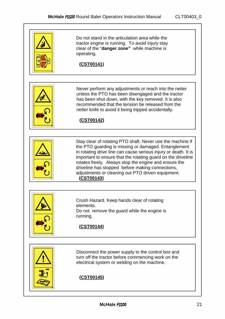
Do not stand in the articulation area while the tractor engine is running. To avoid injury stay clear of the “danger zone” while machine is operating.
(CST00141)
Never perform any adjustments or reach into the netter unless the PTO has been disengaged and the tractor has been shut down, with the key removed. It is also recommended that the tension be released from the netter knife to avoid it being tripped accidentally.
(CST00142)
Crush Hazard. Keep hands clear of rotating elements. Do not remove the guard while the engine is running.
(CST00144)
Disconnect the power supply to the control box and turn off the tractor before commencing work on the electrical system or welding on the machine.
(CST00145)
Stay clear of rotating PTO shaft. Never use the machine if the PTO guarding is missing or damaged. Entanglement in rotating drive line can cause serious injury or death. It is important to ensure that the rotating guard on the driveline rotates freely. Always stop the engine and ensure the driveline has stopped before making connections, adjustments or cleaning out PTO driven equipment. (CST00143)
McHale F5500F5500F5500F5500 22
McHale F5500F5500F5500F5500 Round Baler Operators Instruction Manual CLT00403_0
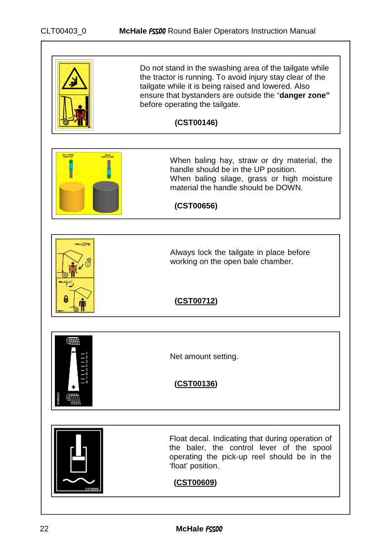
When baling hay, straw or dry material, the handle should be in the UP position. When baling silage, grass or high moisture material the handle should be DOWN. (CST00656)
Net amount setting. (CST00136)
CST00609
Float decal. Indicating that during operation of the baler, the control lever of the spool operating the pick-up reel should be in the ‘float’ position. (CST00609)
Always lock the tailgate in place before working on the open bale chamber. (CST00712)
Do not stand in the swashing area of the tailgate while the tractor is running. To avoid injury stay clear of the tailgate while it is being raised and lowered. Also ensure that bystanders are outside the “danger zone” before operating the tailgate.
(CST00146)
McHale F5500F5500F5500F5500 23
McHale F5500F5500F5500F5500 Round Baler Operators Instruction Manual CLT00403_0
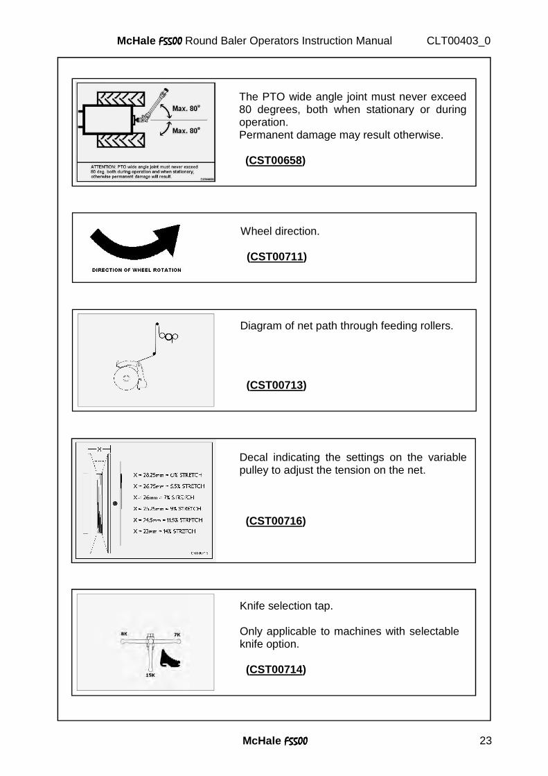
The PTO wide angle joint must never exceed 80 degrees, both when stationary or during operation. Permanent damage may result otherwise. (CST00658)
Diagram of net path through feeding rollers. (CST00713)
Knife selection tap. Only applicable to machines with selectable knife option. (CST00714)
Decal indicating the settings on the variable pulley to adjust the tension on the net. (CST00716)
Wheel direction. (CST00711)
McHale F5500F5500F5500F5500 24
McHale F5500F5500F5500F5500 Round Baler Operators Instruction Manual CLT00403_0
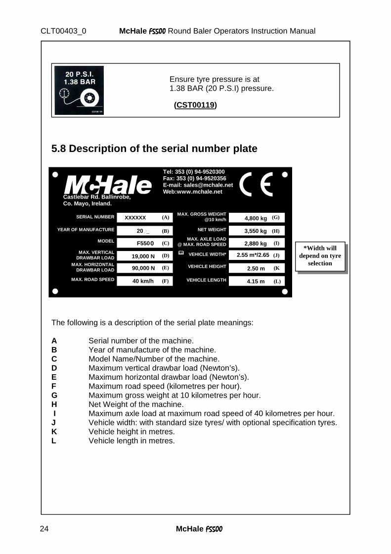
5.8 Description of the serial number plate
The following is a description of the serial plate meanings: A Serial number of the machine. B Year of manufacture of the machine. C Model Name/Number of the machine. D Maximum vertical drawbar load (Newton’s). E Maximum horizontal drawbar load (Newton’s). F Maximum road speed (kilometres per hour). G Maximum gross weight at 10 kilometres per hour. H Net Weight of the machine. I Maximum axle load at maximum road speed of 40 kilometres per hour. J Vehicle width: with standard size tyres/ with optional specification tyres. K Vehicle height in metres. L Vehicle length in metres.
*Width will depend on tyre
selection MAX. HORIZONTAL DRAWBAR LOAD
MAX. VERTICAL DRAWBAR LOAD
Castlebar Rd. Ballinrobe, Co. Mayo, Ireland.
Tel: 353 (0) 94-9520300Fax: 353 (0) 94-9520356 E-mail: [email protected] Web:www.mchale.net
SERIAL NUMBER
YEAR OF MANUFACTURE 200_
F550
19,000 N
90,000 N
40 km/h
4,800 kg
3,550 kg
2,880 kg
2.55 m*/2.65 m*
2.50 m
4.15 m
MODEL
MAX. ROAD SPEED
MAX. GROSS WEIGHT@10 km/h
NET WEIGHT
MAX. AXLE LOAD @ MAX. ROAD SPEED
� � � � VEHICLE WIDTH*
VEHICLE HEIGHT
VEHICLE LENGTH
(A)
(J)
(G)
(H)
(I)
(K
(L)
(B)
(C)
(D)
(E)
(F)
XXXXXX
0
Ensure tyre pressure is at 1.38 BAR (20 P.S.I) pressure. (CST00119)
McHale F5500F5500F5500F5500 25
McHale F5500F5500F5500F5500 Round Baler Operators Instruction Manual CLT00403_0
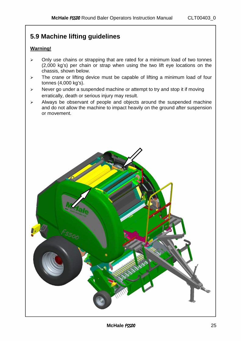
5.9 Machine lifting guidelines Warning! � Only use chains or strapping that are rated for a minimum load of two tonnes
(2,000 kg’s) per chain or strap when using the two lift eye locations on the chassis, shown below.
� The crane or lifting device must be capable of lifting a minimum load of four tonnes (4,000 kg’s).
� Never go under a suspended machine or attempt to try and stop it if moving erratically, death or serious injury may result. � Always be observant of people and objects around the suspended machine
and do not allow the machine to impact heavily on the ground after suspension or movement.

McHale F5500F5500F5500F5500 26
McHale F5500F5500F5500F5500 Round Baler Operators Instruction Manual CLT00403_0
6. Tractor Requirements and Preparations
6.1 Tractor requirements The minimum recommended size of tractor for operating the McHale F5500F5500F5500F5500 comfortably, depends mainly on the crop condition and the required cut length of the forage. On flat ground McHale recommends a tractor size of approximately 75 kW on hilly ground or difficult conditions, an additional 5 to 10 kW are advisable. Note: Ensure that the tractor has clean, good quality, hydraulic/ universal oil to avoid problems later on. Also, the hydraulic filters on the tractor should be changed regularly, according to the manufacturers service instructions. Avoid dirt getting in to the hydraulic couplings. The following items on the tractor are required for attachment of the McHale F5500F5500F5500F5500 behind the tractor: 1. Low/High drawbar hitch* that is suitable for an imposed load of minimum 3600 kg’s.
2. Two double acting spools [½” - female quick release] one with float position for the pick-up reel.
3. One hydraulic-brake coupling (Or two air-brake couplings) If brakes fitted.
4. One 12 V / 7 pin socket for lighting.
5. One 12 V / 20 Amp euro socket or battery power cable.*
6. A 1 ⅜”, 6 spline PTO shaft (set to a speed of 540 rpm).
* Depending on the country of use.
6.2 Control box installation The electronic control box must be located inside the tractor cab in the operator’s field of vision, and within easy reach. It is secured to the glass using the suction pad on the rear. Ensure that the cable to the machine is not under tension and not near sharp edges etc. The electric power supply is obtained from the euro socket in the tractor.
The control box is not waterproof, it must be protected from rain. See section 8 on Electronic control system.
Caution! Do not use any other electric power supply for the electronic system, otherwise damage may occur!
McHale F5500F5500F5500F5500 27
McHale F5500F5500F5500F5500 Round Baler Operators Instruction Manual CLT00403_0
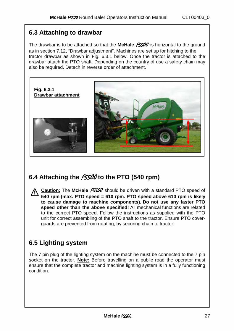
6.3 Attaching to drawbar The drawbar is to be attached so that the McHale F5500F5500F5500F5500 is horizontal to the ground as in section 7.12, “Drawbar adjustment”. Machines are set up for hitching to the tractor drawbar as shown in Fig. 6.3.1 below. Once the tractor is attached to the drawbar attach the PTO shaft. Depending on the country of use a safety chain may also be required. Detach in reverse order of attachment.
6.4 Attaching the F5500F5500F5500F5500 to the PTO (540 rpm)
Caution: The McHale F5500F5500F5500F5500 should be driven with a standard PTO speed of 540 rpm (max. PTO speed = 610 rpm. PTO speed above 610 rpm is likely to cause damage to machine components). Do not use any faster PTO speed other than the above specified! All mechanical functions are related to the correct PTO speed. Follow the instructions as supplied with the PTO unit for correct assembling of the PTO shaft to the tractor. Ensure PTO cover-guards are prevented from rotating, by securing chain to tractor.
6.5 Lighting system The 7 pin plug of the lighting system on the machine must be connected to the 7 pin socket on the tractor. Note: Before travelling on a public road the operator must ensure that the complete tractor and machine lighting system is in a fully functioning condition.
Fig. 6.3.1 Drawbar attachment
5400
McHale F5500F5500F5500F5500 28
McHale F5500F5500F5500F5500 Round Baler Operators Instruction Manual CLT00403_0
6.6 Attaching the hydraulic hosing to the tractor
Warning! When connecting hydraulic hosing to the tractor ensure that the tractor engine is turned off and that the ignition key is removed.
Ensure that all hydraulic connections are correctly tightened. There are a total of four hydraulic hoses that must be connected to the tractor. They are as follows: A One ½” male quick release for door open (max. flow 70 litres per minute).
B One ½” male quick release for door close (max. flow 70 litres per minute).
C One ½” male quick release for pick-up reel Up (Drop Floor/Knives UP).*
D One ½” male quick release for pick-up reel Down (Drop Floor/Knives Down).* E One hydraulic-brake coupling (Or two air-brake couplings), If brakes fitted.
G One 12 V / 7 pin lighting socket.
H One 12 V / 20 Amp euro socket .
* With either the drop floor or the knife diverter valve activated.
6.7 Connecting the control box The control box is to be connected to a 12V / 20 Amp power supply using the supplied euro lead. A good power supply is critical for proper machine operation as the electronic control box is the main interface between the operator and the machine.
Caution: Do not attempt to connect control box to a power supply greater than 12V as machine component damage will result.
McHale F5500F5500F5500F5500 29
McHale F5500F5500F5500F5500 Round Baler Operators Instruction Manual CLT00403_0
7. Baler Requirements and Preparation 7.1 Net requirements In order for the McHale F5500 F5500 F5500 F5500 to produce well-shaped bales of excellent density a top quality net, that is as similar as possible, to the specification recommended below should be used. It is of the utmost importance that the net is stored and used according to the instructions of the net manufacturer. Note: For netting silage a minimum of two revolutions of net is recommended, but when material is drier, netting amount should be increased to four or more revolutions. A general rule to follow is to apply the amount of net that will maintain the bale size. The maximum bale size recommended is a 1.27m diameter bale. In order to achieve the best possible performance, McHale recommend the use of a net roll which meets the following specifications: � Material: High quality, high density polyethylene.
� Density: Minimum of 10 g/m2 ±10%.
� Elongation: 15% ±3%.
� Strength (In direction of wrap): 900 N/ 500 mm.
� Material Length 2000 – 4000 m ±200 m.
� Material Width (Ideal) 1230 mm, Note: 1300mm max.
7.2 Care of the net roll The net roll should be protected from damage and moisture. Do not remove protective cover until ready for use. Net damage can cause undesired netter performance and affect bale weather ability. 7.3 Care of the net wrapping system Before operating the baler ensure that the following procedure is followed to ensure improved netter operation:
Clean off rubber and aluminium feed rollers and check for any tacky material. Never use cleaning agents such as benzene, petrol, turpentine oil or similar cleaning solvents to clean rubber feed roll, otherwise damage may occur!
McHale recommend to use any of the following: � A cloth soaked in dish washing liquid. � Soapy water. Note: Once roller cleaning is carried out, dry off and apply talcum powder to the rubber feed roller.
McHale F5500F5500F5500F5500 30
McHale F5500F5500F5500F5500 Round Baler Operators Instruction Manual CLT00403_0
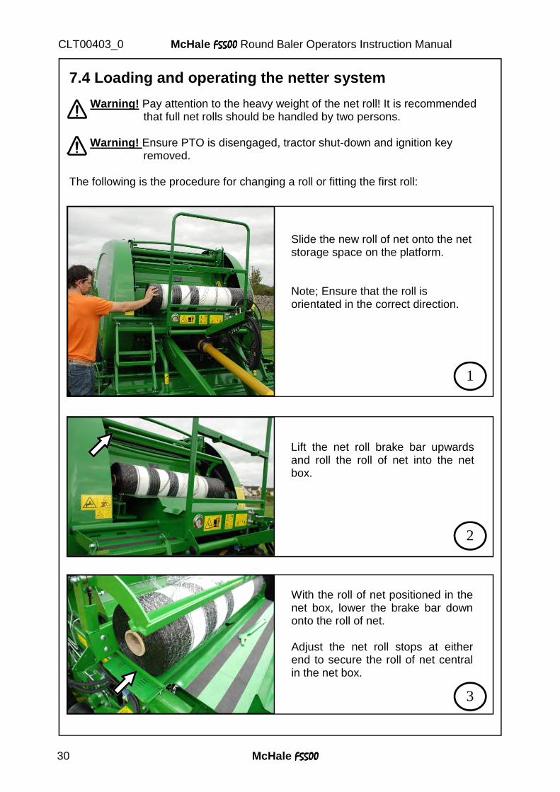
7.4 Loading and operating the netter system Warning! Pay attention to the heavy weight of the net roll! It is recommended that full net rolls should be handled by two persons. Warning! Ensure PTO is disengaged, tractor shut-down and ignition key removed.
The following is the procedure for changing a roll or fitting the first roll:
Slide the new roll of net onto the net storage space on the platform. Note; Ensure that the roll is orientated in the correct direction.
1
2
Lift the net roll brake bar upwards and roll the roll of net into the net box.
3
With the roll of net positioned in the net box, lower the brake bar down onto the roll of net. Adjust the net roll stops at either end to secure the roll of net central in the net box.
McHale F5500F5500F5500F5500 31
McHale F5500F5500F5500F5500 Round Baler Operators Instruction Manual CLT00403_0
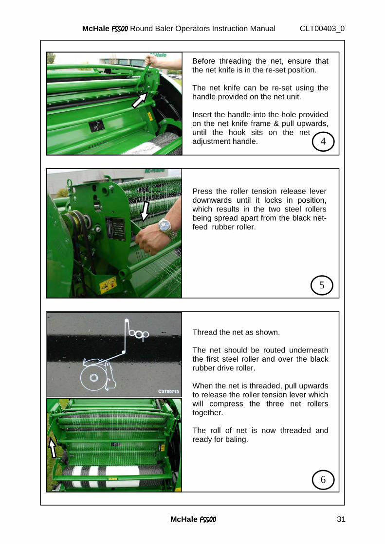
Before threading the net, ensure that the net knife is in the re-set position. The net knife can be re-set using the handle provided on the net unit. Insert the handle into the hole provided on the net knife frame & pull upwards, until the hook sits on the net adjustment handle. 4
Press the roller tension release lever downwards until it locks in position, which results in the two steel rollers being spread apart from the black net- feed rubber roller.
5
Thread the net as shown. The net should be routed underneath the first steel roller and over the black rubber drive roller. When the net is threaded, pull upwards to release the roller tension lever which will compress the three net rollers together. The roll of net is now threaded and ready for baling.
6
McHale F5500F5500F5500F5500 32
McHale F5500F5500F5500F5500 Round Baler Operators Instruction Manual CLT00403_0
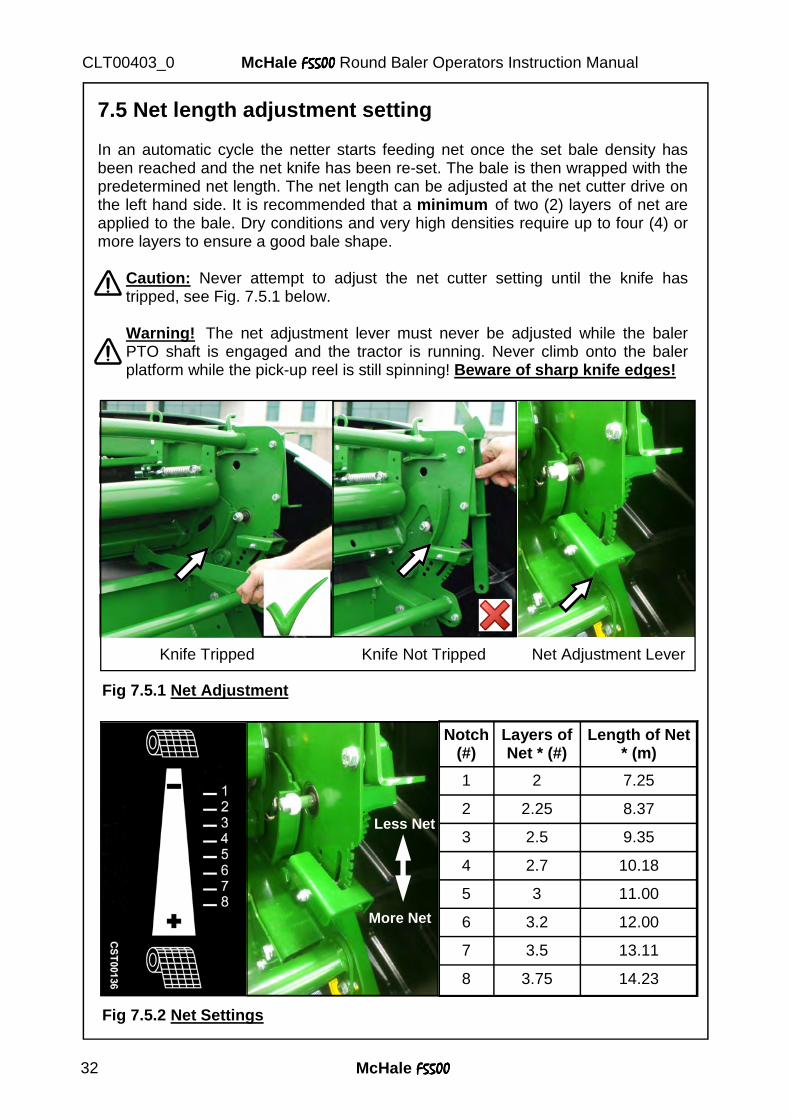
7.5 Net length adjustment setting In an automatic cycle the netter starts feeding net once the set bale density has been reached and the net knife has been re-set. The bale is then wrapped with the predetermined net length. The net length can be adjusted at the net cutter drive on the left hand side. It is recommended that a minimum of two (2) layers of net are applied to the bale. Dry conditions and very high densities require up to four (4) or more layers to ensure a good bale shape.
Caution: Never attempt to adjust the net cutter setting until the knife has tripped, see Fig. 7.5.1 below.
Warning! The net adjustment lever must never be adjusted while the baler PTO shaft is engaged and the tractor is running. Never climb onto the baler platform while the pick-up reel is still spinning! Beware of sharp knife edges!
Knife Tripped Knife Not Tripped Net Adjustment Lever
Fig 7.5.1 Net Adjustment
Fig 7.5.2 Net Settings
Less Net
More Net
Notch (#)
Layers of Net * (#)
Length of Net * (m)
1 2 7.25
2 2.25 8.37
3 2.5 9.35
4 2.7 10.18
5 3 11.00
6 3.2 12.00
7 3.5 13.11
8 3.75 14.23
McHale F5500F5500F5500F5500 33
McHale F5500F5500F5500F5500 Round Baler Operators Instruction Manual CLT00403_0
Adjustment is achieved by pushing the adjustment lever to the right in order to release latch from the notches, then choose the desired notch, upwards or downwards, for less or more net, to be applied (as shown in Fig. 7.5.2) before re-engaging. The notches are sequenced from top to bottom and are numbered from 1 to 8 respectively. See table in Fig. 7.5.2 for exact amount of net applied for each specific notch. * Note: Always ensure that the bill hook rests on the adjuster lever as shown in middle picture in Fig. 7.5.1. * Note: Figures in table 7.5.2 are calculated assuming a bale circumference of 3.77m (a bale diameter of 1.2m). The value of the layers of net and length of net, will be approximate figures only, due to differing bale diameters, varying crop conditions etc.
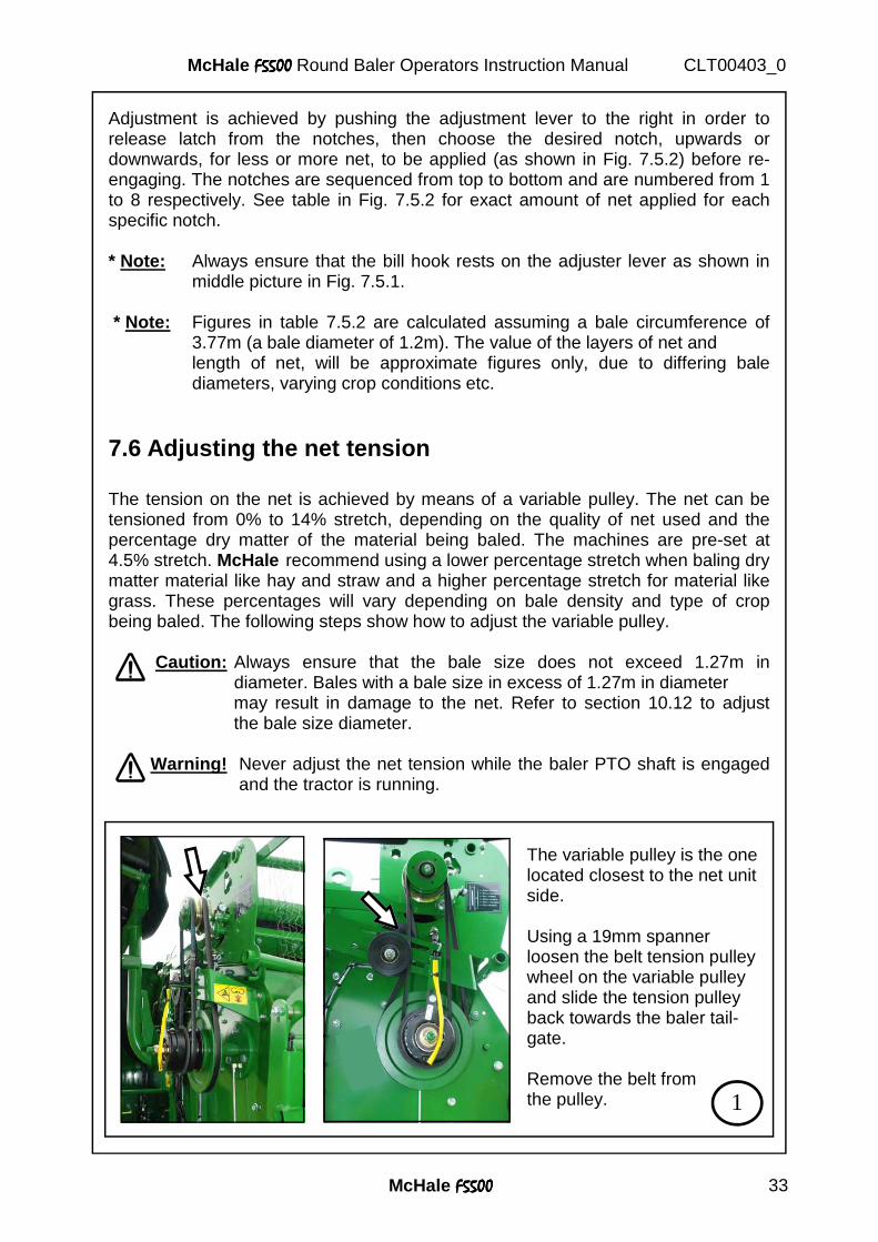
7.6 Adjusting the net tension The tension on the net is achieved by means of a variable pulley. The net can be tensioned from 0% to 14% stretch, depending on the quality of net used and the percentage dry matter of the material being baled. The machines are pre-set at 4.5% stretch. McHale recommend using a lower percentage stretch when baling dry matter material like hay and straw and a higher percentage stretch for material like grass. These percentages will vary depending on bale density and type of crop being baled. The following steps show how to adjust the variable pulley.
Caution: Always ensure that the bale size does not exceed 1.27m in diameter. Bales with a bale size in excess of 1.27m in diameter
may result in damage to the net. Refer to section 10.12 to adjust the bale size diameter.
Warning! Never adjust the net tension while the baler PTO shaft is engaged and the tractor is running.
The variable pulley is the one located closest to the net unit side. Using a 19mm spanner loosen the belt tension pulley wheel on the variable pulley and slide the tension pulley back towards the baler tail-gate. Remove the belt from the pulley. 1
McHale F5500F5500F5500F5500 34
McHale F5500F5500F5500F5500 Round Baler Operators Instruction Manual CLT00403_0
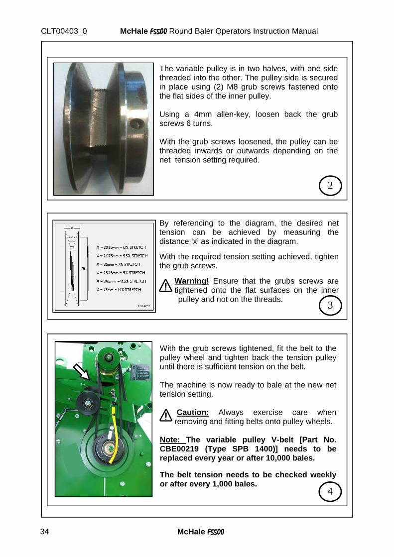
The variable pulley is in two halves, with one side threaded into the other. The pulley side is secured in place using (2) M8 grub screws fastened onto the flat sides of the inner pulley. Using a 4mm allen-key, loosen back the grub screws 6 turns. With the grub screws loosened, the pulley can be threaded inwards or outwards depending on the net tension setting required.
2
By referencing to the diagram, the desired net tension can be achieved by measuring the distance ‘x’ as indicated in the diagram.
With the required tension setting achieved, tighten the grub screws.
Warning! Ensure that the grubs screws are tightened onto the flat surfaces on the inner
pulley and not on the threads. 3
With the grub screws tightened, fit the belt to the pulley wheel and tighten back the tension pulley until there is sufficient tension on the belt. The machine is now ready to bale at the new net tension setting.
Caution: Always exercise care when removing and fitting belts onto pulley wheels.
Note: The variable pulley V-belt [Part No. CBE00219 (Type SPB 1400)] needs to be replaced every year or after 10,000 bales. The belt tension needs to be checked weekly or after every 1,000 bales.
4
McHale F5500F5500F5500F5500 35
McHale F5500F5500F5500F5500 Round Baler Operators Instruction Manual CLT00403_0
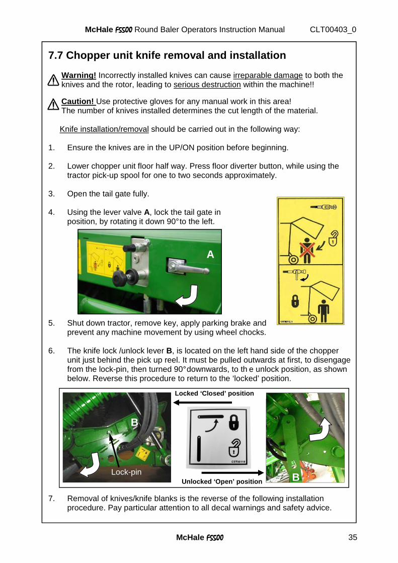
7.7 Chopper unit knife removal and installation
Warning! Incorrectly installed knives can cause irreparable damage to both the knives and the rotor, leading to serious destruction within the machine!! Caution! Use protective gloves for any manual work in this area! The number of knives installed determines the cut length of the material. Knife installation/removal should be carried out in the following way:
1. Ensure the knives are in the UP/ON position before beginning. 2. Lower chopper unit floor half way. Press floor diverter button, while using the
tractor pick-up spool for one to two seconds approximately.
3. Open the tail gate fully. 4. Using the lever valve A, lock the tail gate in position, by rotating it down 90° to the left. 5. Shut down tractor, remove key, apply parking brake and
prevent any machine movement by using wheel chocks.
6. The knife lock /unlock lever B, is located on the left hand side of the chopper unit just behind the pick up reel. It must be pulled outwards at first, to disengage from the lock-pin, then turned 90° downwards, to th e unlock position, as shown below. Reverse this procedure to return to the ‘locked’ position.
7. Removal of knives/knife blanks is the reverse of the following installation
procedure. Pay particular attention to all decal warnings and safety advice.
A
B
Lock-pin B
Locked ‘Closed’ position
Unlocked ‘Open’ position
McHale F5500F5500F5500F5500 36
McHale F5500F5500F5500F5500 Round Baler Operators Instruction Manual CLT00403_0
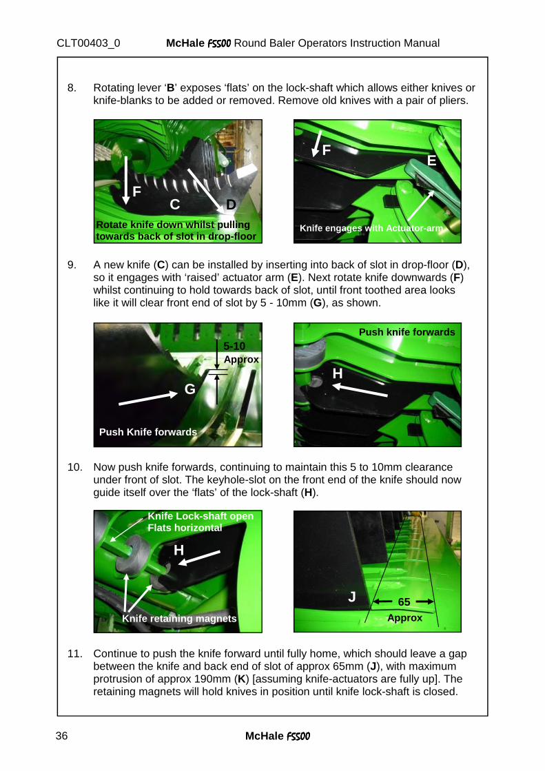
8. Rotating lever ‘B’ exposes ‘flats’ on the lock-shaft which allows either knives or
knife-blanks to be added or removed. Remove old knives with a pair of pliers. 9. A new knife (C) can be installed by inserting into back of slot in drop-floor (D),
so it engages with ‘raised’ actuator arm (E). Next rotate knife downwards (F) whilst continuing to hold towards back of slot, until front toothed area looks like it will clear front end of slot by 5 - 10mm (G), as shown.
10. Now push knife forwards, continuing to maintain this 5 to 10mm clearance
under front of slot. The keyhole-slot on the front end of the knife should now guide itself over the ‘flats’ of the lock-shaft (H).
11. Continue to push the knife forward until fully home, which should leave a gap
between the knife and back end of slot of approx 65mm (J), with maximum protrusion of approx 190mm (K) [assuming knife-actuators are fully up]. The retaining magnets will hold knives in position until knife lock-shaft is closed.
Knife engages with Actuator-arm Rotate knife down whilst pulling towards back of slot in drop-floor
5-10 Approx
Push Knife forwards
Push knife forwards
Knife Lock-shaft open Flats horizontal
Knife retaining magnets
65 Approx
C D F
G
F
H
H
J
E
McHale F5500F5500F5500F5500 37
McHale F5500F5500F5500F5500 Round Baler Operators Instruction Manual CLT00403_0
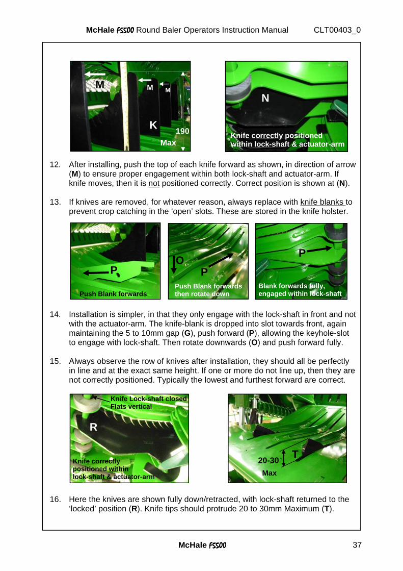
12. After installing, push the top of each knife forward as shown, in direction of arrow
(M) to ensure proper engagement within both lock-shaft and actuator-arm. If knife moves, then it is not positioned correctly. Correct position is shown at (N).
13. If knives are removed, for whatever reason, always replace with knife blanks to
prevent crop catching in the ‘open’ slots. These are stored in the knife holster.
14. Installation is simpler, in that they only engage with the lock-shaft in front and not with the actuator-arm. The knife-blank is dropped into slot towards front, again maintaining the 5 to 10mm gap (G), push forward (P), allowing the keyhole-slot to engage with lock-shaft. Then rotate downwards (O) and push forward fully.
15. Always observe the row of knives after installation, they should all be perfectly
in line and at the exact same height. If one or more do not line up, then they are not correctly positioned. Typically the lowest and furthest forward are correct.
16. Here the knives are shown fully down/retracted, with lock-shaft returned to the ‘locked’ position (R). Knife tips should protrude 20 to 30mm Maximum (T).
Knife correctly positioned within lock-shaft & actuator-arm Max
190 K
M M M
N
20-30
Max
Knife Lock-shaft closed Flats vertical
Knife correctly positioned within lock-shaft & actuator-arm
Push Blank forwards Blank forwards fully, engaged within lock-shaft
P
P Push Blank forwards then rotate down
O P
R
T
McHale F5500F5500F5500F5500 38
McHale F5500F5500F5500F5500 Round Baler Operators Instruction Manual CLT00403_0
17. Rotating lever B back up 90° onto lock-pin, locks all knives/blanks securely. 18. The knife blanks are stored in the knife/ knife blank holster. (Fig. 7.7.1 below)
Warning! Do not forget to turn the levers back into there working positions, but only after having finished all work on the baler.
Warning! Always keep the compartment door panels closed while the machine is running, danger of rotating components! Note the warning decals and ensure that all safety measures and precautions are carried out before attempting to carry out any maintenance work.
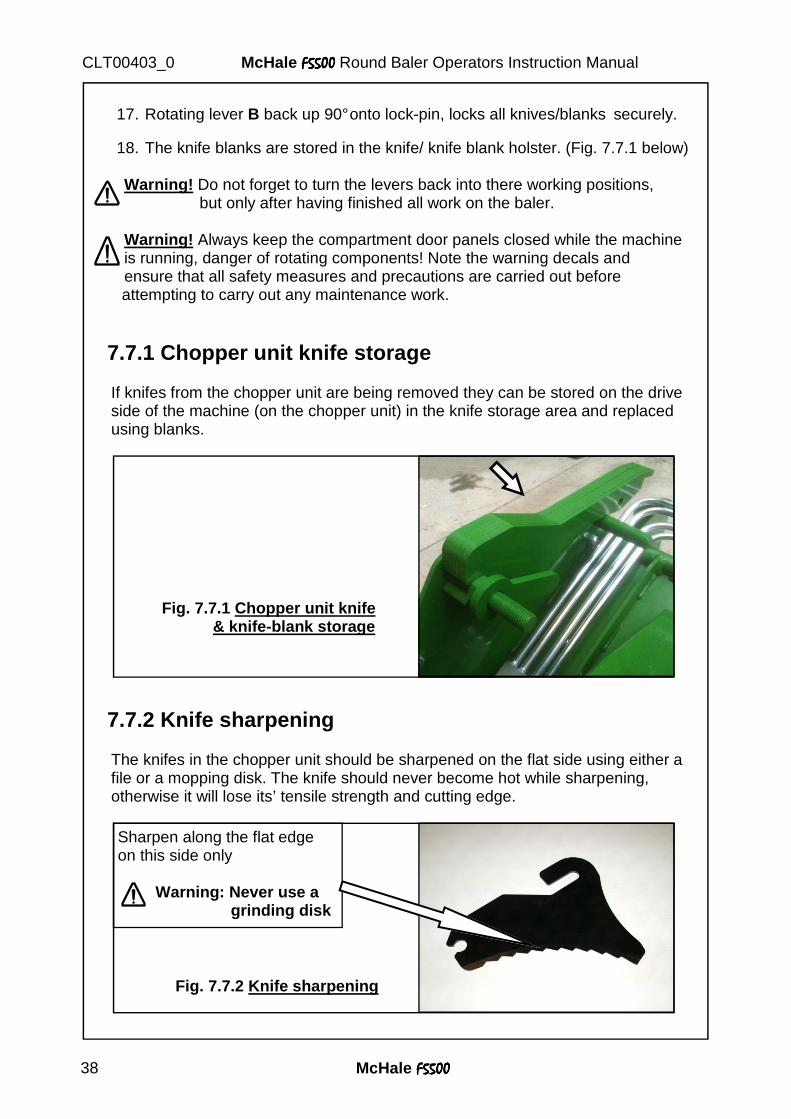
7.7.1 Chopper unit knife storage
If knifes from the chopper unit are being removed they can be stored on the drive side of the machine (on the chopper unit) in the knife storage area and replaced using blanks.
7.7.2 Knife sharpening
The knifes in the chopper unit should be sharpened on the flat side using either a file or a mopping disk. The knife should never become hot while sharpening, otherwise it will lose its’ tensile strength and cutting edge.
Sharpen along the flat edge on this side only Warning: Never use a grinding disk
Fig. 7.7.2 Knife sharpening
Fig. 7.7.1 Chopper unit knife & knife-blank storage
McHale F5500F5500F5500F5500 39
McHale F5500F5500F5500F5500 Round Baler Operators Instruction Manual CLT00403_0
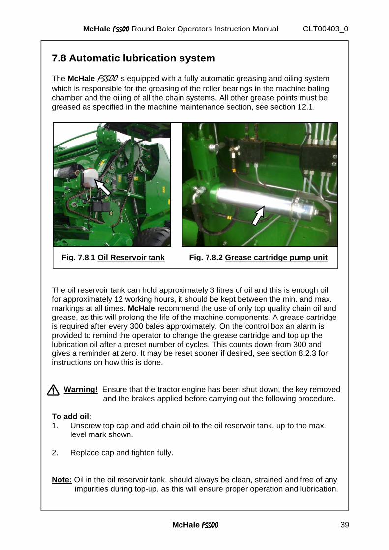
7.8 Automatic lubrication system The McHale F5500 is equipped with a fully automatic greasing and oiling system which is responsible for the greasing of the roller bearings in the machine baling chamber and the oiling of all the chain systems. All other grease points must be greased as specified in the machine maintenance section, see section 12.1.
The oil reservoir tank can hold approximately 3 litres of oil and this is enough oil for approximately 12 working hours, it should be kept between the min. and max. markings at all times. McHale recommend the use of only top quality chain oil and grease, as this will prolong the life of the machine components. A grease cartridge is required after every 300 bales approximately. On the control box an alarm is provided to remind the operator to change the grease cartridge and top up the lubrication oil after a preset number of cycles. This counts down from 300 and gives a reminder at zero. It may be reset sooner if desired, see section 8.2.3 for instructions on how this is done.
Warning! Ensure that the tractor engine has been shut down, the key removed and the brakes applied before carrying out the following procedure.
To add oil: 1. Unscrew top cap and add chain oil to the oil reservoir tank, up to the max.
level mark shown. 2. Replace cap and tighten fully. Note: Oil in the oil reservoir tank, should always be clean, strained and free of any impurities during top-up, as this will ensure proper operation and lubrication.
Fig. 7.8.1 Oil Reservoir tank Fig. 7.8.2 Grease cartridge pump unit
McHale F5500F5500F5500F5500 40
McHale F5500F5500F5500F5500 Round Baler Operators Instruction Manual CLT00403_0
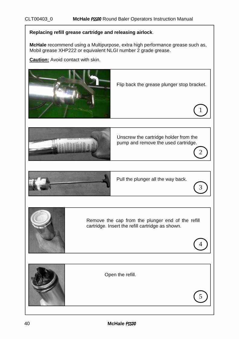
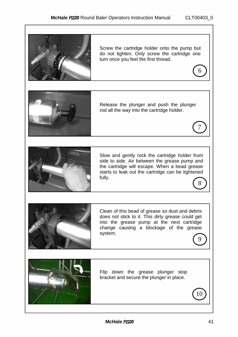
Replacing refill grease cartridge and releasing airlock .
McHale recommend using a Multipurpose, extra high performance grease such as, Mobil grease XHP222 or equivalent NLGI number 2 grade grease.
Caution: Avoid contact with skin.
Unscrew the cartridge holder from the pump and remove the used cartridge.
2
Pull the plunger all the way back.
3
Remove the cap from the plunger end of the refill cartridge. Insert the refill cartridge as shown.
4
Open the refill.
5
Flip back the grease plunger stop bracket.
1
McHale F5500F5500F5500F5500 41
McHale F5500F5500F5500F5500 Round Baler Operators Instruction Manual CLT00403_0
8
Slow and gently rock the cartridge holder from side to side. Air between the grease pump and the cartridge will escape. When a bead grease starts to leak out the cartridge can be tightened fully.
7
Release the plunger and push the plunger rod all the way into the cartridge holder.
6
Screw the cartridge holder onto the pump but do not tighten. Only screw the cartridge one turn once you feel the first thread.
9
Clean of this bead of grease so dust and debris does not stick to it. This dirty grease could get into the grease pump at the next cartridge change causing a blockage of the grease system.
10
Flip down the grease plunger stop bracket and secure the plunger in place.
McHale F5500F5500F5500F5500 42
McHale F5500F5500F5500F5500 Round Baler Operators Instruction Manual CLT00403_0
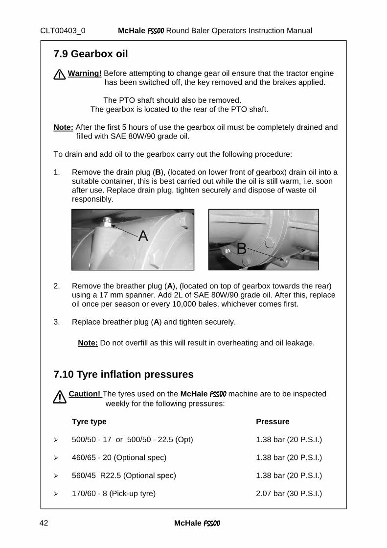
7.9 Gearbox oil Warning! Before attempting to change gear oil ensure that the tractor engine has been switched off, the key removed and the brakes applied.
The PTO shaft should also be removed. The gearbox is located to the rear of the PTO shaft. Note: After the first 5 hours of use the gearbox oil must be completely drained and filled with SAE 80W/90 grade oil. To drain and add oil to the gearbox carry out the following procedure: 1. Remove the drain plug (B), (located on lower front of gearbox) drain oil into a
suitable container, this is best carried out while the oil is still warm, i.e. soon after use. Replace drain plug, tighten securely and dispose of waste oil responsibly.
2. Remove the breather plug (A), (located on top of gearbox towards the rear) using a 17 mm spanner. Add 2L of SAE 80W/90 grade oil. After this, replace oil once per season or every 10,000 bales, whichever comes first.
3. Replace breather plug (A) and tighten securely.
Note: Do not overfill as this will result in overheating and oil leakage.
7.10 Tyre inflation pressures
Caution! The tyres used on the McHale F5500F5500F5500F5500 machine are to be inspected weekly for the following pressures: Tyre type Pressure
� 500/50 - 17 or 500/50 - 22.5 (Opt) 1.38 bar (20 P.S.I.) � 460/65 - 20 (Optional spec) 1.38 bar (20 P.S.I.) � 560/45 R22.5 (Optional spec) 1.38 bar (20 P.S.I.) � 170/60 - 8 (Pick-up tyre) 2.07 bar (30 P.S.I.)

McHale F5500F5500F5500F5500 43
McHale F5500F5500F5500F5500 Round Baler Operators Instruction Manual CLT00403_0
McHale F5500F5500F5500F5500 44
McHale F5500F5500F5500F5500 Round Baler Operators Instruction Manual CLT00403_0
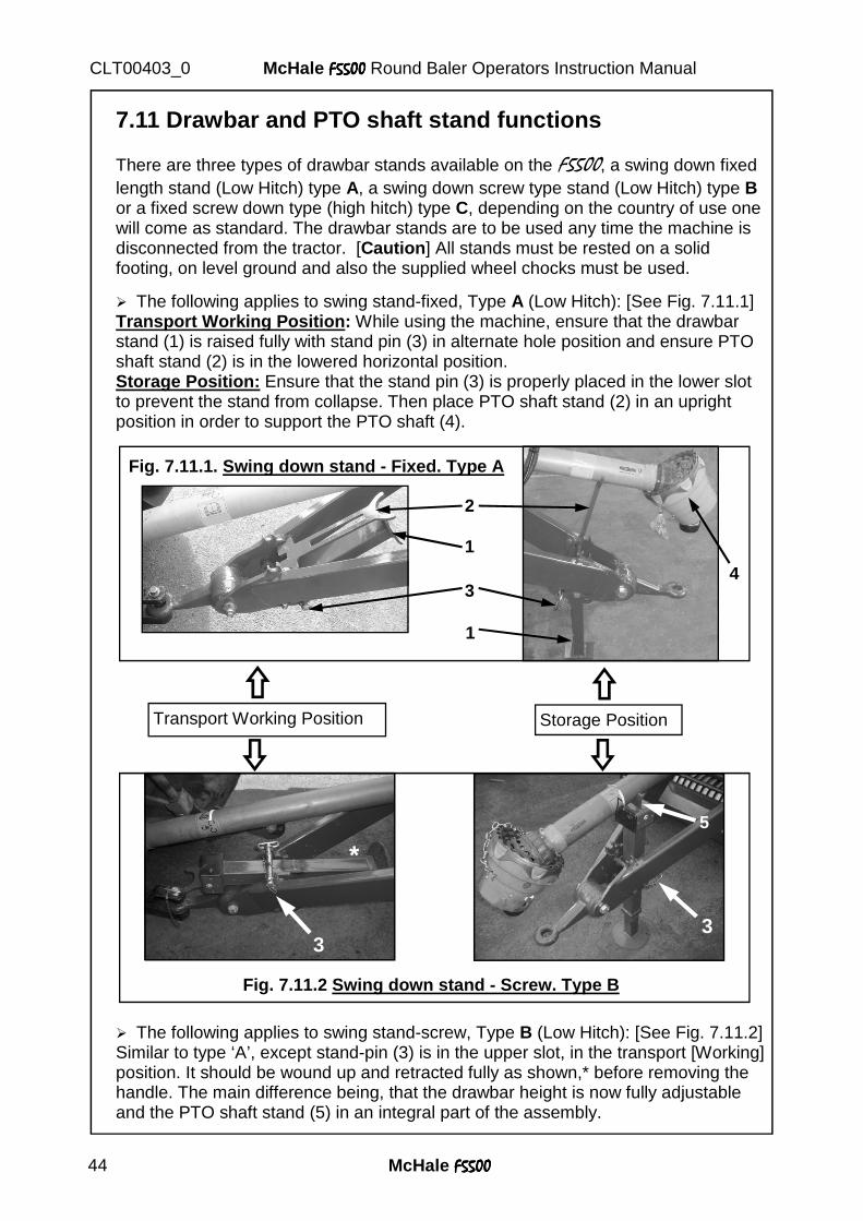
7.11 Drawbar and PTO shaft stand functions There are three types of drawbar stands available on the F5500, a swing down fixed length stand (Low Hitch) type A, a swing down screw type stand (Low Hitch) type B or a fixed screw down type (high hitch) type C, depending on the country of use one will come as standard. The drawbar stands are to be used any time the machine is disconnected from the tractor. [Caution ] All stands must be rested on a solid footing, on level ground and also the supplied wheel chocks must be used.
� The following applies to swing stand-fixed, Type A (Low Hitch): [See Fig. 7.11.1] Transport Working Position : While using the machine, ensure that the drawbar stand (1) is raised fully with stand pin (3) in alternate hole position and ensure PTO shaft stand (2) is in the lowered horizontal position. Storage Position: Ensure that the stand pin (3) is properly placed in the lower slot to prevent the stand from collapse. Then place PTO shaft stand (2) in an upright position in order to support the PTO shaft (4).
� The following applies to swing stand-screw, Type B (Low Hitch): [See Fig. 7.11.2] Similar to type ‘A’, except stand-pin (3) is in the upper slot, in the transport [Working] position. It should be wound up and retracted fully as shown,* before removing the handle. The main difference being, that the drawbar height is now fully adjustable and the PTO shaft stand (5) in an integral part of the assembly.
Transport Working Position Storage Position
Fig. 7.11.2 Swing down stand - Screw. Type B
3
* 5
3
1
2
3
1
4
Fig. 7.11.1. Swing down stand - Fixed. Type A
McHale F5500F5500F5500F5500 45
McHale F5500F5500F5500F5500 Round Baler Operators Instruction Manual CLT00403_0
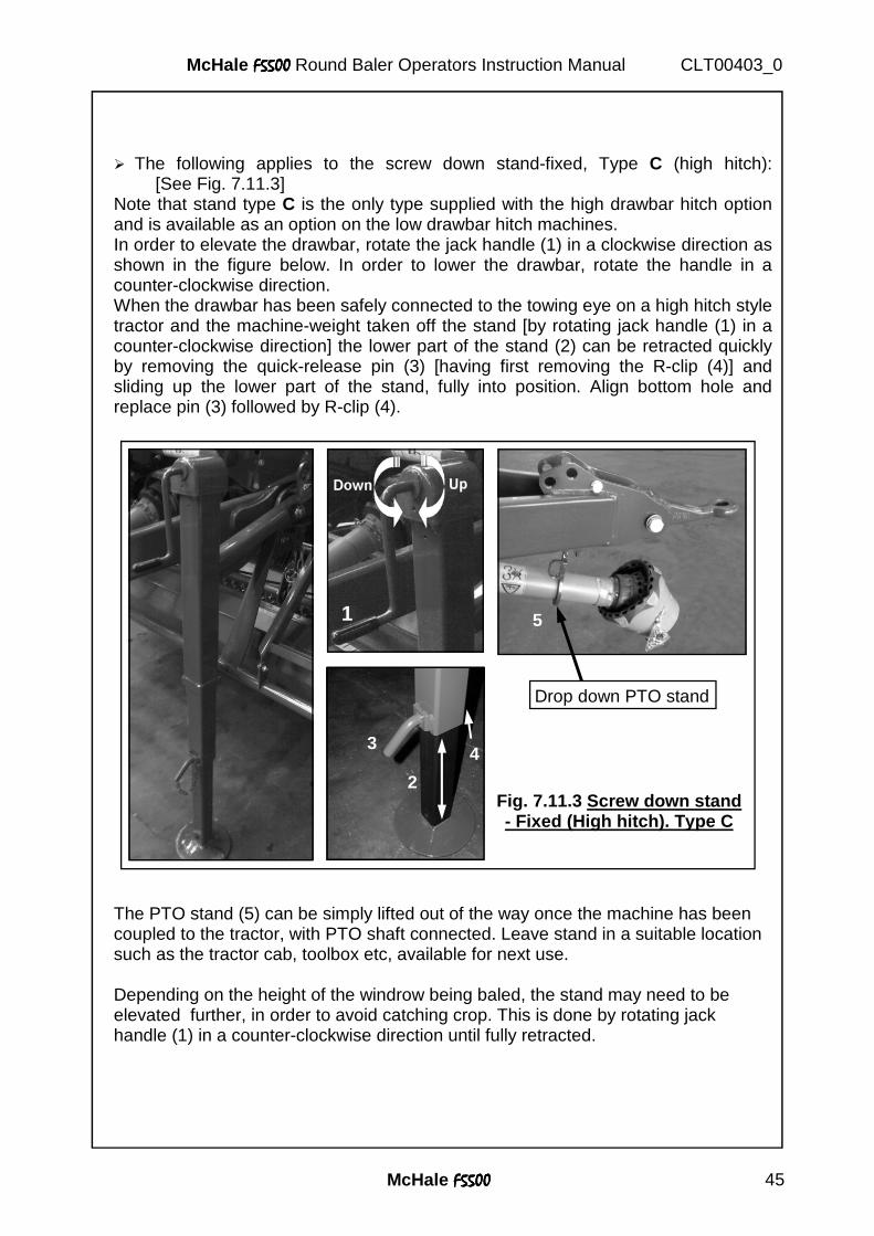
� The following applies to the screw down stand-fixed, Type C (high hitch): [See Fig. 7.11.3]
Note that stand type C is the only type supplied with the high drawbar hitch option and is available as an option on the low drawbar hitch machines. In order to elevate the drawbar, rotate the jack handle (1) in a clockwise direction as shown in the figure below. In order to lower the drawbar, rotate the handle in a counter-clockwise direction. When the drawbar has been safely connected to the towing eye on a high hitch style tractor and the machine-weight taken off the stand [by rotating jack handle (1) in a counter-clockwise direction] the lower part of the stand (2) can be retracted quickly by removing the quick-release pin (3) [having first removing the R-clip (4)] and sliding up the lower part of the stand, fully into position. Align bottom hole and replace pin (3) followed by R-clip (4).
The PTO stand (5) can be simply lifted out of the way once the machine has been coupled to the tractor, with PTO shaft connected. Leave stand in a suitable location such as the tractor cab, toolbox etc, available for next use. Depending on the height of the windrow being baled, the stand may need to be elevated further, in order to avoid catching crop. This is done by rotating jack handle (1) in a counter-clockwise direction until fully retracted.
Fig. 7.11.3 Screw down stand - Fixed (High hitch). Type C
3 4
5
Drop down PTO stand
2
1
McHale F5500F5500F5500F5500 46
McHale F5500F5500F5500F5500 Round Baler Operators Instruction Manual CLT00403_0
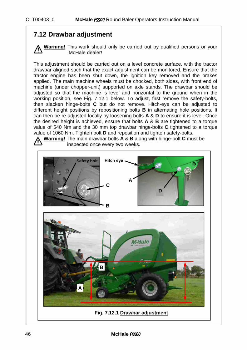
7.12 Drawbar adjustment
Warning! This work should only be carried out by qualified persons or your McHale dealer!
This adjustment should be carried out on a level concrete surface, with the tractor drawbar aligned such that the exact adjustment can be monitored. Ensure that the tractor engine has been shut down, the ignition key removed and the brakes applied. The main machine wheels must be chocked, both sides, with front end of machine (under chopper-unit) supported on axle stands. The drawbar should be adjusted so that the machine is level and horizontal to the ground when in the working position, see Fig. 7.12.1 below. To adjust, first remove the safety-bolts, then slacken hinge-bolts C but do not remove. Hitch-eye can be adjusted to different height positions by repositioning bolts B in alternating hole positions. It can then be re-adjusted locally by loosening bolts A & D to ensure it is level. Once the desired height is achieved, ensure that bolts A & B are tightened to a torque value of 540 Nm and the 30 mm top drawbar hinge-bolts C tightened to a torque value of 1060 Nm. Tighten bolt D and reposition and tighten safety-bolts.
Warning! The main drawbar bolts A & B along with hinge-bolt C must be inspected once every two weeks.
Fig. 7.12.1 Drawbar adjustment
A
B
C
B
Safety bolt
A
D
Hitch eye
D
5500
McHale F5500F5500F5500F5500 47
McHale F5500F5500F5500F5500 Round Baler Operators Instruction Manual CLT00403_0
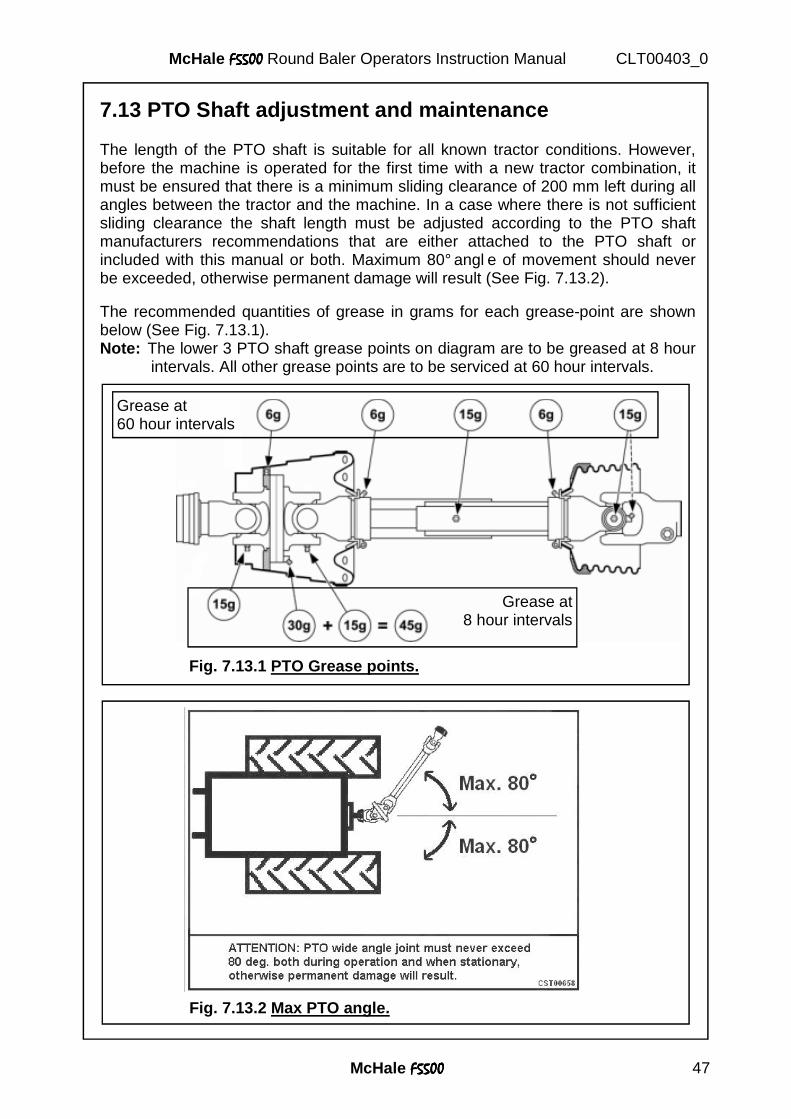
7.13 PTO Shaft adjustment and maintenance The length of the PTO shaft is suitable for all known tractor conditions. However, before the machine is operated for the first time with a new tractor combination, it must be ensured that there is a minimum sliding clearance of 200 mm left during all angles between the tractor and the machine. In a case where there is not sufficient sliding clearance the shaft length must be adjusted according to the PTO shaft manufacturers recommendations that are either attached to the PTO shaft or included with this manual or both. Maximum 80° angl e of movement should never be exceeded, otherwise permanent damage will result (See Fig. 7.13.2). The recommended quantities of grease in grams for each grease-point are shown below (See Fig. 7.13.1). Note: The lower 3 PTO shaft grease points on diagram are to be greased at 8 hour intervals. All other grease points are to be serviced at 60 hour intervals.
Grease at 60 hour intervals
Grease at 8 hour intervals
Fig. 7.13.1 PTO Grease points.
Fig. 7.13.2 Max PTO angle.
McHale F5500F5500F5500F5500 48
McHale F5500F5500F5500F5500 Round Baler Operators Instruction Manual CLT00403_0
1
5
3 4 2 8 7
6
Fig. 1
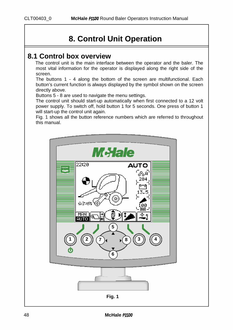
8.1 Control box overview The control unit is the main interface between the operator and the baler. The
most vital information for the operator is displayed along the right side of the screen.
The buttons 1 - 4 along the bottom of the screen are multifunctional. Each button’s current function is always displayed by the symbol shown on the screen directly above.
Buttons 5 - 8 are used to navigate the menu settings. The control unit should start-up automatically when first connected to a 12 volt
power supply. To switch off, hold button 1 for 5 seconds. One press of button 1 will start-up the control unit again.
Fig. 1 shows all the button reference numbers which are referred to throughout this manual.
8. Control Unit Operation
McHale F5500F5500F5500F5500 49
McHale F5500F5500F5500F5500 Round Baler Operators Instruction Manual CLT00403_0
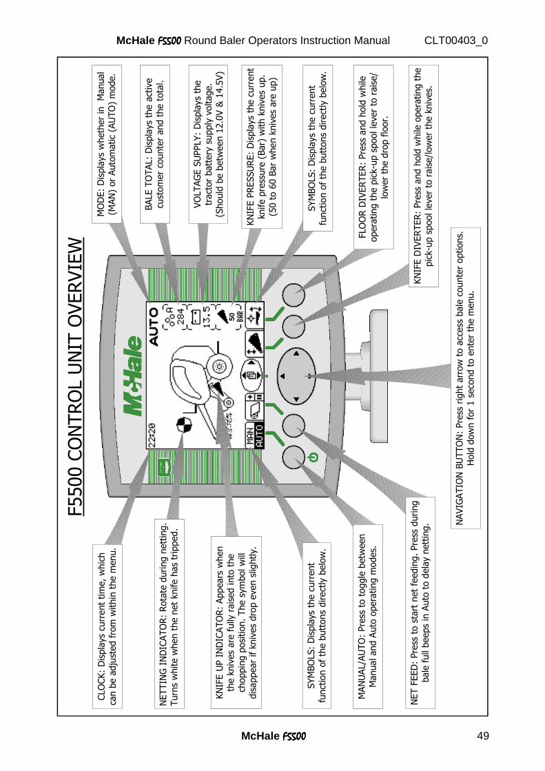
NET F
EED
: Pre
ss t
o s
tart
net
feedin
g. Pre
ss d
uring
bale
full
beeps
in A
uto
to d
ela
y n
ett
ing. N
AVIG
ATIO
N B
UTTO
N:
Pre
ss r
ight
arr
ow
to a
ccess
bale
counte
r options.
Hold
dow
n f
or
1 s
eco
nd t
o e
nte
r th
e m
enu.
KN
IFE D
IVER
TER
: Pre
ss a
nd h
old
while
opera
ting t
he
pic
k-u
p s
pool le
ver
to r
ais
e/l
ow
er
the k
niv
es.
50
NETTIN
G I
ND
ICATO
R:
Rota
te d
uring n
ett
ing.
Turn
s w
hite w
hen t
he n
et
knife h
as
trip
ped.
CLO
CK:
Dis
pla
ys
curr
ent
tim
e, w
hic
h
can b
e a
dju
sted f
rom
within
the m
enu.
F5500 C
ON
TRO
L U
NIT
OVERVIE
W FLO
OR
DIV
ER
TER
: Pre
ss a
nd h
old
while
opera
ting t
he p
ick-u
p s
pool le
ver
to r
ais
e/
low
er
the d
rop f
loor.
SYM
BO
LS:
Dis
pla
ys
the c
urr
ent
funct
ion o
f th
e b
utt
ons
direct
ly b
elo
w.
KN
IFE U
P I
ND
ICATO
R:
Appears
when
the k
niv
es
are
fully
rais
ed into
the
choppin
g p
osi
tion.
The s
ym
bol w
ill
dis
appear
if k
niv
es
dro
p e
ven s
lightly.
SYM
BO
LS:
Dis
pla
ys
the c
urr
ent
funct
ion o
f th
e b
utt
ons
direct
ly b
elo
w.
MAN
UAL/A
UTO
: Pre
ss t
o t
oggle
betw
een
Manual and A
uto
opera
ting m
odes.
KN
IFE P
RESSU
RE:
Dis
pla
ys
the c
urr
ent
knife p
ress
ure
(Bar)
with k
niv
es
up.
(50 t
o 6
0 B
ar
when k
niv
es
are
up)
VO
LTAG
E S
UPPLY:
Dis
pla
ys
the
tract
or
batt
ery
supply
voltage.
(Should
be b
etw
een 1
2.0
V &
14.5
V)
BALE T
OTAL:
Dis
pla
ys
the a
ctiv
e
cust
om
er
counte
r and t
he t
ota
l.
MO
DE:
Dis
pla
ys
wheth
er
in
Manual
(MAN
) or
Auto
matic
(AU
TO
) m
ode.
McHale F5500F5500F5500F5500 50
McHale F5500F5500F5500F5500 Round Baler Operators Instruction Manual CLT00403_0
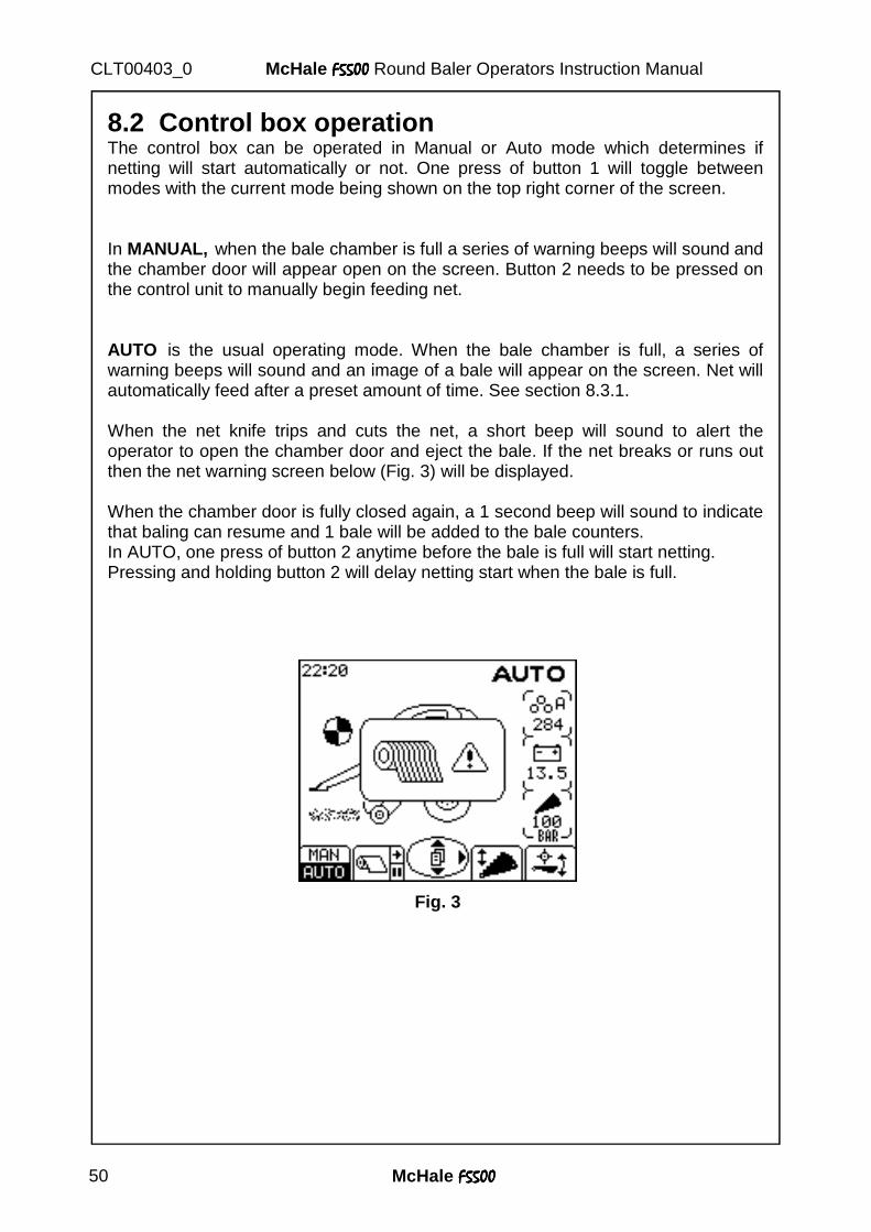
8.2 Control box operation The control box can be operated in Manual or Auto mode which determines if netting will start automatically or not. One press of button 1 will toggle between modes with the current mode being shown on the top right corner of the screen. In MANUAL, when the bale chamber is full a series of warning beeps will sound and the chamber door will appear open on the screen. Button 2 needs to be pressed on the control unit to manually begin feeding net. AUTO is the usual operating mode. When the bale chamber is full, a series of warning beeps will sound and an image of a bale will appear on the screen. Net will automatically feed after a preset amount of time. See section 8.3.1. When the net knife trips and cuts the net, a short beep will sound to alert the operator to open the chamber door and eject the bale. If the net breaks or runs out then the net warning screen below (Fig. 3) will be displayed. When the chamber door is fully closed again, a 1 second beep will sound to indicate that baling can resume and 1 bale will be added to the bale counters. In AUTO, one press of button 2 anytime before the bale is full will start netting. Pressing and holding button 2 will delay netting start when the bale is full.
Fig. 3
McHale F5500F5500F5500F5500 51
McHale F5500F5500F5500F5500 Round Baler Operators Instruction Manual CLT00403_0
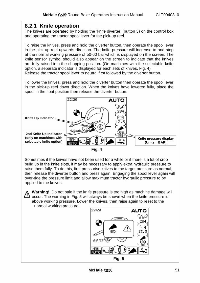
8.2.1 Knife operation The knives are operated by holding the ‘knife diverter’ (button 3) on the control box and operating the tractor spool lever for the pick-up reel. To raise the knives, press and hold the diverter button, then operate the spool lever in the pick-up reel upwards direction. The knife pressure will increase to and stop at the normal working pressure of 50-60 bar which is displayed on the screen. The knife sensor symbol should also appear on the screen to indicate that the knives are fully raised into the chopping position. (On machines with the selectable knife option, a separate indicator is displayed for each sets of knives, Fig. 4) Release the tractor spool lever to neutral first followed by the diverter button. To lower the knives, press and hold the diverter button then operate the spool lever in the pick-up reel down direction. When the knives have lowered fully, place the spool in the float position then release the diverter button.
Fig. 5
Sometimes if the knives have not been used for a while or if there is a lot of crop build up in the knife slots, it may be necessary to apply extra hydraulic pressure to raise them fully. To do this, first pressurise knives to the target pressure as normal, then release the diverter button and press again. Engaging the spool lever again will over-ride the pressure limit and allow maximum tractor hydraulic pressure to be applied to the knives.
Warning! Do not bale if the knife pressure is too high as machine damage will occur. The warning in Fig. 5 will always be shown when the knife pressure is above working pressure. Lower the knives, then raise again to reset to the normal working pressure.
Knife pressure display (Units = BAR)
Knife Up Indicator
Fig. 4
2nd Knife Up Indicator (only on machines with selectable knife option)
McHale F5500F5500F5500F5500 52
McHale F5500F5500F5500F5500 Round Baler Operators Instruction Manual CLT00403_0
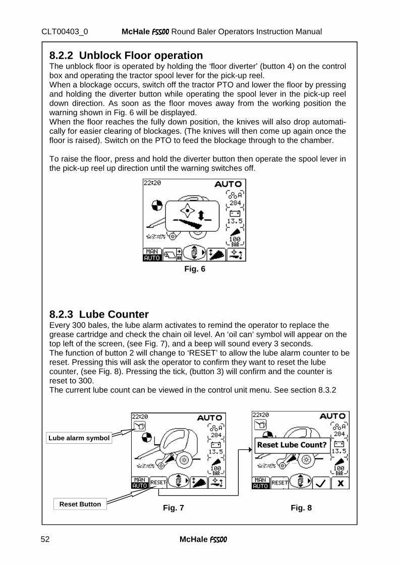
8.2.2 Unblock Floor operation The unblock floor is operated by holding the ‘floor diverter’ (button 4) on the control box and operating the tractor spool lever for the pick-up reel. When a blockage occurs, switch off the tractor PTO and lower the floor by pressing and holding the diverter button while operating the spool lever in the pick-up reel down direction. As soon as the floor moves away from the working position the warning shown in Fig. 6 will be displayed. When the floor reaches the fully down position, the knives will also drop automati-cally for easier clearing of blockages. (The knives will then come up again once the floor is raised). Switch on the PTO to feed the blockage through to the chamber. To raise the floor, press and hold the diverter button then operate the spool lever in the pick-up reel up direction until the warning switches off.
Fig. 6
8.2.3 Lube Counter Every 300 bales, the lube alarm activates to remind the operator to replace the grease cartridge and check the chain oil level. An ‘oil can’ symbol will appear on the top left of the screen, (see Fig. 7), and a beep will sound every 3 seconds. The function of button 2 will change to ‘RESET’ to allow the lube alarm counter to be reset. Pressing this will ask the operator to confirm they want to reset the lube counter, (see Fig. 8). Pressing the tick, (button 3) will confirm and the counter is reset to 300. The current lube count can be viewed in the control unit menu. See section 8.3.2
Fig. 7
Lube alarm symbol
Reset Button
Reset Lube Count?
X
Fig. 8
McHale F5500F5500F5500F5500 53
McHale F5500F5500F5500F5500 Round Baler Operators Instruction Manual CLT00403_0
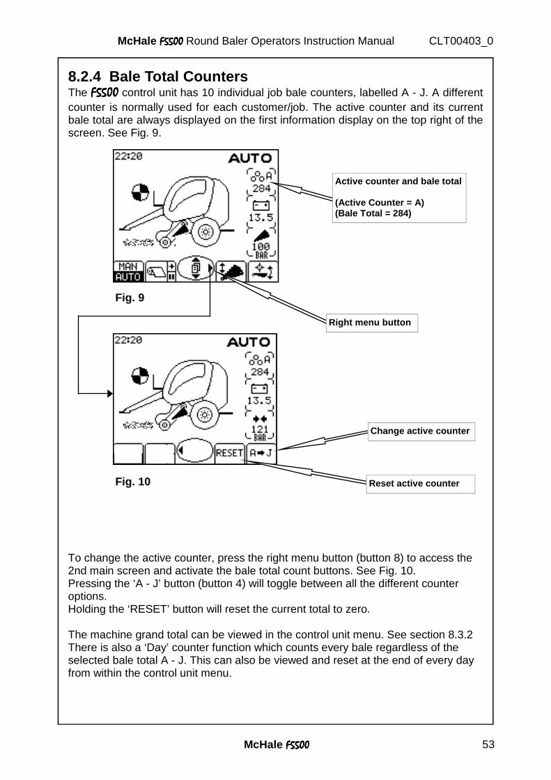
8.2.4 Bale Total Counters The F5500F5500F5500F5500 control unit has 10 individual job bale counters, labelled A - J. A different counter is normally used for each customer/job. The active counter and its current bale total are always displayed on the first information display on the top right of the screen. See Fig. 9.
To change the active counter, press the right menu button (button 8) to access the 2nd main screen and activate the bale total count buttons. See Fig. 10. Pressing the ‘A - J’ button (button 4) will toggle between all the different counter options. Holding the ‘RESET’ button will reset the current total to zero. The machine grand total can be viewed in the control unit menu. See section 8.3.2 There is also a ‘Day’ counter function which counts every bale regardless of the selected bale total A - J. This can also be viewed and reset at the end of every day from within the control unit menu.
Fig. 9
Right menu button
Fig. 10 Reset active counter
Change active counter
Active counter and bale total (Active Counter = A) (Bale Total = 284)
McHale F5500F5500F5500F5500 54
McHale F5500F5500F5500F5500 Round Baler Operators Instruction Manual CLT00403_0
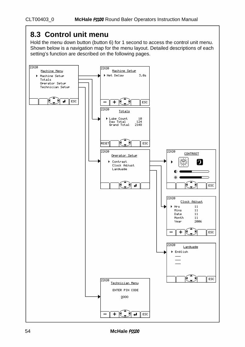
8.3 Control unit menu Hold the menu down button (button 6) for 1 second to access the control unit menu. Shown below is a navigation map for the menu layout. Detailed descriptions of each setting’s function are described on the following pages.
McHale F5500F5500F5500F5500 55
McHale F5500F5500F5500F5500 Round Baler Operators Instruction Manual CLT00403_0
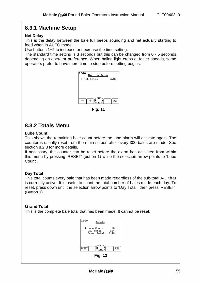
8.3.1 Machine Setup Net Delay This is the delay between the bale full beeps sounding and net actually starting to feed when in AUTO mode. Use buttons 1+2 to increase or decrease the time setting. The standard time setting is 3 seconds but this can be changed from 0 - 5 seconds depending on operator preference. When baling light crops at faster speeds, some operators prefer to have more time to stop before netting begins.
8.3.2 Totals Menu Lube Count This shows the remaining bale count before the lube alarm will activate again. The counter is usually reset from the main screen after every 300 bales are made. See section 8.2.3 for more details. If necessary, the counter can be reset before the alarm has activated from within this menu by pressing ‘RESET’ (button 1) while the selection arrow points to ‘Lube Count’.
Day Total This total counts every bale that has been made regardless of the sub-total A-J that is currently active. It is useful to count the total number of bales made each day. To reset, press down until the selection arrow points to ‘Day Total’, then press ‘RESET’ (Button 1).
Grand Total This is the complete bale total that has been made. It cannot be reset.
Fig. 11
Fig. 12
McHale F5500F5500F5500F5500 56
McHale F5500F5500F5500F5500 Round Baler Operators Instruction Manual CLT00403_0
8.3.3 Operator Setup
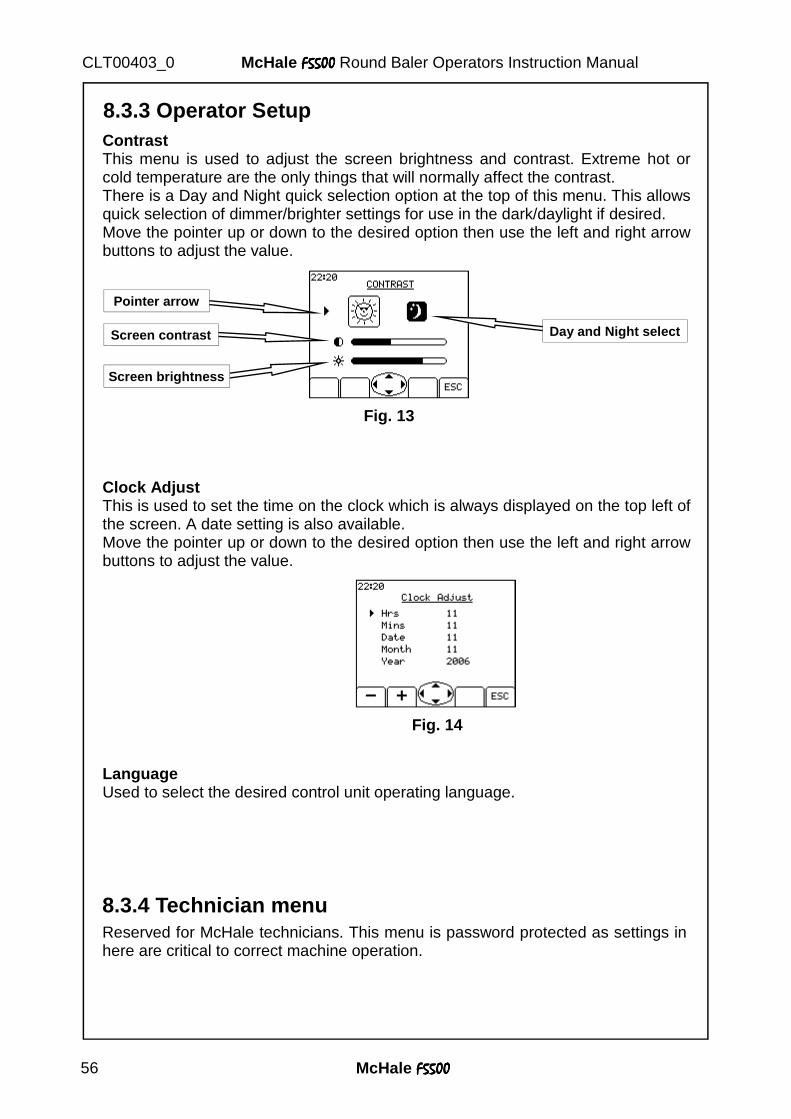
Contrast This menu is used to adjust the screen brightness and contrast. Extreme hot or cold temperature are the only things that will normally affect the contrast. There is a Day and Night quick selection option at the top of this menu. This allows quick selection of dimmer/brighter settings for use in the dark/daylight if desired. Move the pointer up or down to the desired option then use the left and right arrow buttons to adjust the value.
Screen brightness
Screen contrast
Pointer arrow
Day and Night select
Clock Adjust This is used to set the time on the clock which is always displayed on the top left of the screen. A date setting is also available. Move the pointer up or down to the desired option then use the left and right arrow buttons to adjust the value.
Language Used to select the desired control unit operating language.
Reserved for McHale technicians. This menu is password protected as settings in here are critical to correct machine operation.
8.3.4 Technician menu
Fig. 13
Fig. 14
McHale F5500F5500F5500F5500 57
McHale F5500F5500F5500F5500 Round Baler Operators Instruction Manual CLT00403_0
8.4 Warning Screens
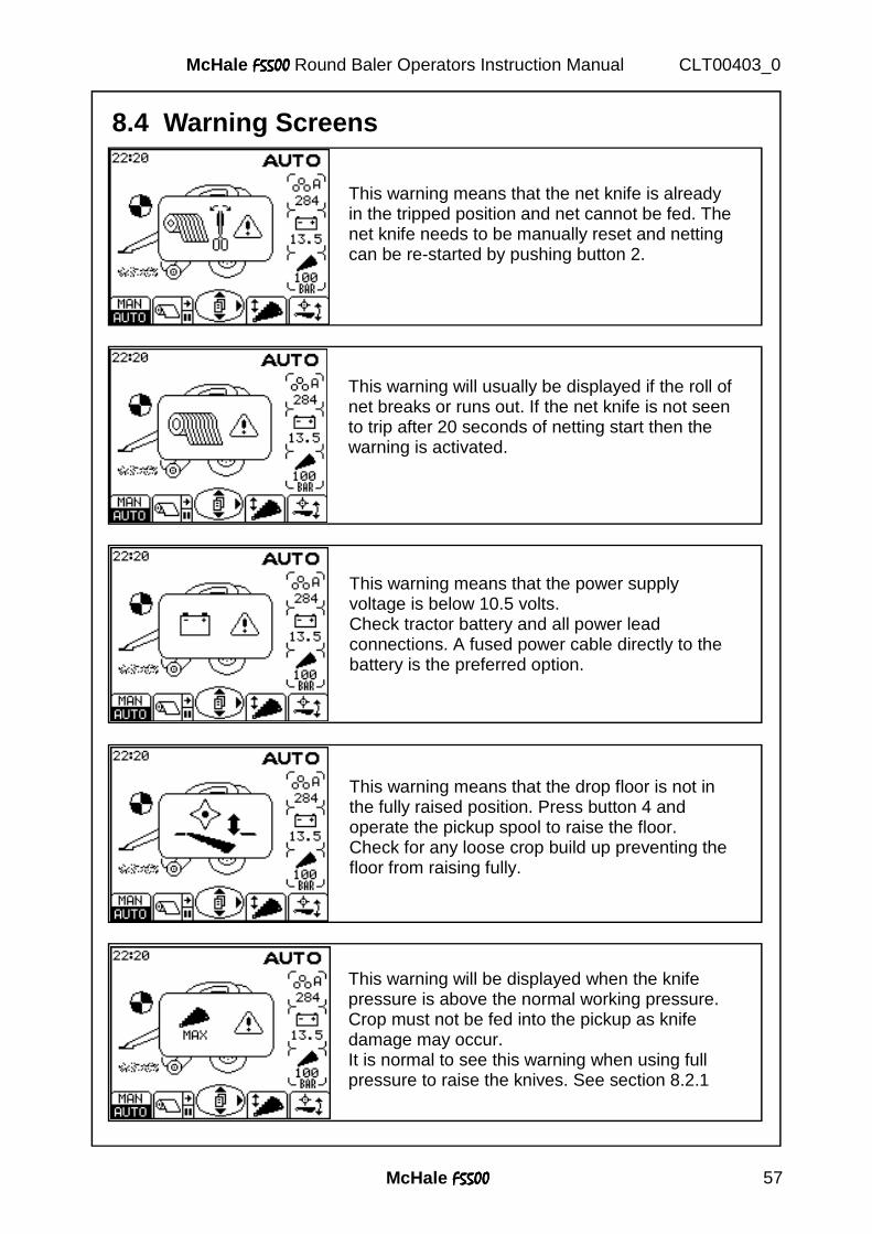
This warning means that the net knife is already in the tripped position and net cannot be fed. The net knife needs to be manually reset and netting can be re-started by pushing button 2.
This warning will usually be displayed if the roll of net breaks or runs out. If the net knife is not seen to trip after 20 seconds of netting start then the warning is activated.
This warning means that the power supply voltage is below 10.5 volts. Check tractor battery and all power lead connections. A fused power cable directly to the battery is the preferred option.
This warning means that the drop floor is not in the fully raised position. Press button 4 and operate the pickup spool to raise the floor. Check for any loose crop build up preventing the floor from raising fully.
This warning will be displayed when the knife pressure is above the normal working pressure. Crop must not be fed into the pickup as knife damage may occur. It is normal to see this warning when using full pressure to raise the knives. See section 8.2.1

McHale F5500F5500F5500F5500 58
McHale F5500F5500F5500F5500 Round Baler Operators Instruction Manual CLT00403_0
This will be displayed if the knives lower even slightly while baling to warn the operator of less than optimum crop chopping. The knives may be blunt or a hydraulic problem may be causing the knife pressure to drop too low allowing the knives to retract.
McHale F5500F5500F5500F5500 59
McHale F5500F5500F5500F5500 Round Baler Operators Instruction Manual CLT00403_0
9. Road Traffic Safety and Operation 9.1 Before travelling on any public roadway .
Warning! Ensure that all of the following are inspected each time before attempting to go on to a public roadway, always think and practice
safety. � Ensure that the tyres are set to the correct pressure as per safety decals and
according to the specifications as outlined in section 14.4. � Ensure that all doors are securely closed and fastened, ensuring that primary
catches are fully engaged, these should be kept clear of all foreign objects to ensure proper and trouble free operation.
� The bale forming chamber should be emptied. � The machine must be safely cleared of all loose forage, to carry this out,
firstly turn off the tractor and fully isolate the machine by disconnecting all of the connections to the tractor unit.
� The PTO shaft must be fixed safely to the tractor PTO stub shaft. � The lighting system of the machine must be connected to the tractor and
must be in a fully functioning condition. � The electronic control box must be disconnected from the power supply. � The hydraulic supply must be turned off and protected from accidental
activation by disconnecting the hydraulic feed line, support all loose lines in a safe manner.
� The pick-up guide wheels must be removed and secured to the machine. � Attention must be paid to the maximum travel speed [40 km/hr] printed on the
chassis plate on the left hand side of the machine. Other speed limits that may be printed, on the drawbar plate or axle plate, for example are not relevant.
� Ensure that all the national road traffic regulations relating to the country are
fulfilled i.e. the use of safety chains may be mandatory in certain countries.
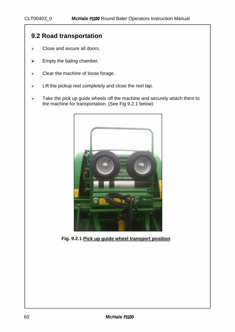
McHale F5500F5500F5500F5500 60
McHale F5500F5500F5500F5500 Round Baler Operators Instruction Manual CLT00403_0
9.2 Road transportation � Close and secure all doors. ���� Empty the baling chamber. � Clear the machine of loose forage. � Lift the pickup reel completely and close the reel tap. � Take the pick up guide wheels off the machine and securely attach them to
the machine for transportation. (See Fig 9.2.1 below)
Fig. 9.2.1 Pick up guide wheel transport position
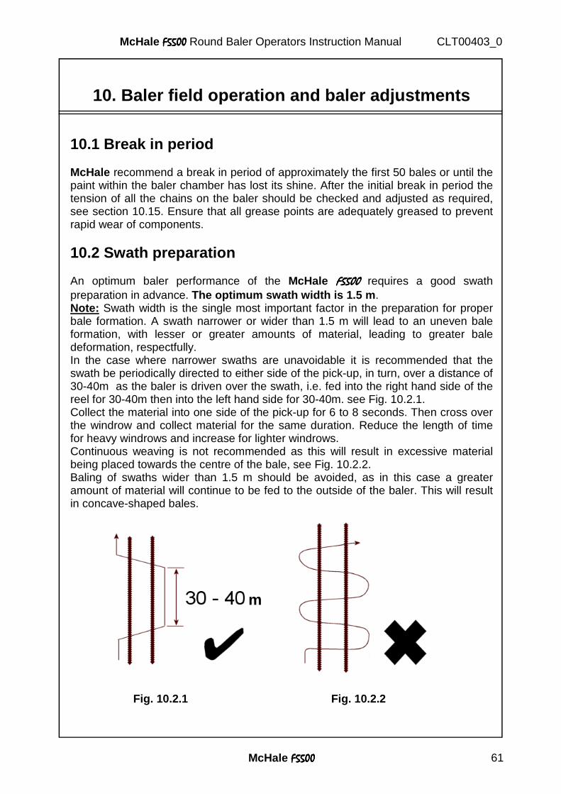
McHale F5500F5500F5500F5500 61
McHale F5500F5500F5500F5500 Round Baler Operators Instruction Manual CLT00403_0
10. Baler field operation and baler adjustments
10.1 Break in period McHale recommend a break in period of approximately the first 50 bales or until the paint within the baler chamber has lost its shine. After the initial break in period the tension of all the chains on the baler should be checked and adjusted as required, see section 10.15. Ensure that all grease points are adequately greased to prevent rapid wear of components.
10.2 Swath preparation An optimum baler performance of the McHale F5500F5500F5500F5500 requires a good swath preparation in advance. The optimum swath width is 1.5 m . Note: Swath width is the single most important factor in the preparation for proper bale formation. A swath narrower or wider than 1.5 m will lead to an uneven bale formation, with lesser or greater amounts of material, leading to greater bale deformation, respectfully. In the case where narrower swaths are unavoidable it is recommended that the swath be periodically directed to either side of the pick-up, in turn, over a distance of 30-40m as the baler is driven over the swath, i.e. fed into the right hand side of the reel for 30-40m then into the left hand side for 30-40m. see Fig. 10.2.1. Collect the material into one side of the pick-up for 6 to 8 seconds. Then cross over the windrow and collect material for the same duration. Reduce the length of time for heavy windrows and increase for lighter windrows. Continuous weaving is not recommended as this will result in excessive material being placed towards the centre of the bale, see Fig. 10.2.2. Baling of swaths wider than 1.5 m should be avoided, as in this case a greater amount of material will continue to be fed to the outside of the baler. This will result in concave-shaped bales. Fig. 10.2.1 Fig. 10.2.2
m
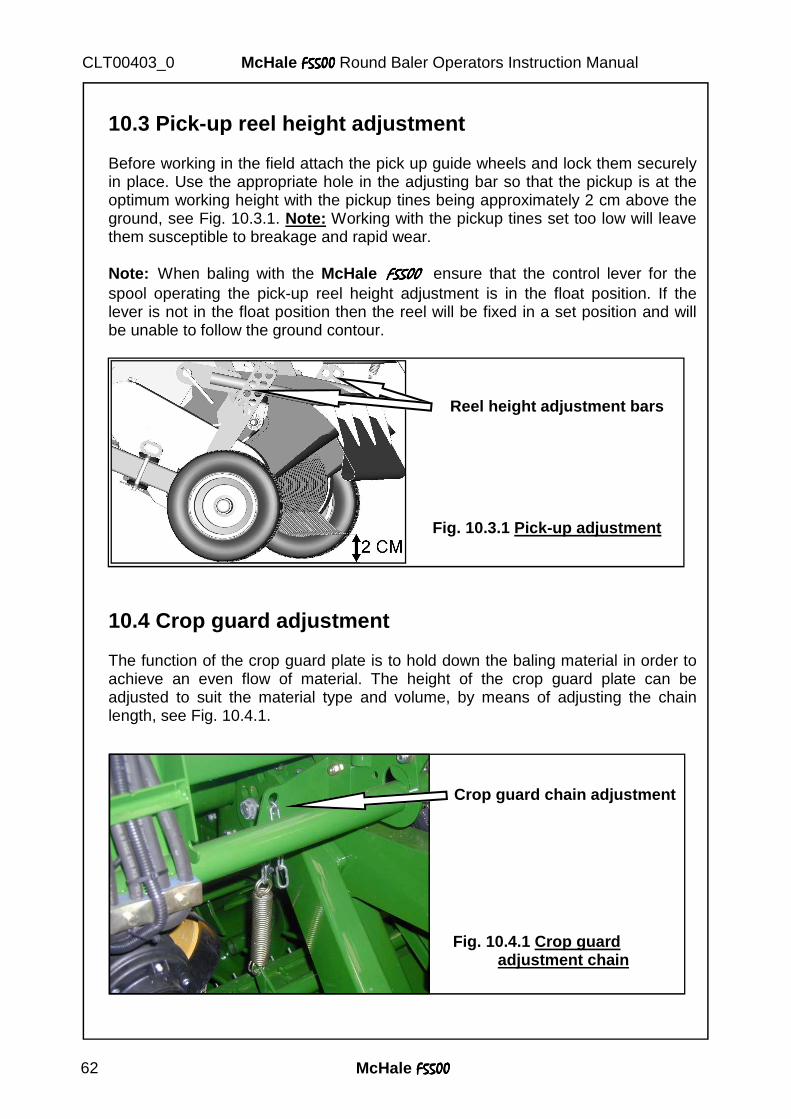
McHale F5500F5500F5500F5500 62
McHale F5500F5500F5500F5500 Round Baler Operators Instruction Manual CLT00403_0
10.3 Pick-up reel height adjustment Before working in the field attach the pick up guide wheels and lock them securely in place. Use the appropriate hole in the adjusting bar so that the pickup is at the optimum working height with the pickup tines being approximately 2 cm above the ground, see Fig. 10.3.1. Note: Working with the pickup tines set too low will leave them susceptible to breakage and rapid wear. Note: When baling with the McHale F5500F5500F5500F5500 ensure that the control lever for the spool operating the pick-up reel height adjustment is in the float position. If the lever is not in the float position then the reel will be fixed in a set position and will be unable to follow the ground contour.
10.4 Crop guard adjustment The function of the crop guard plate is to hold down the baling material in order to achieve an even flow of material. The height of the crop guard plate can be adjusted to suit the material type and volume, by means of adjusting the chain length, see Fig. 10.4.1.
Reel height adjustment bars
Fig. 10.3.1 Pick-up adjustment
Crop guard chain adjustment
Fig. 10.4.1 Crop guard adjustment chain
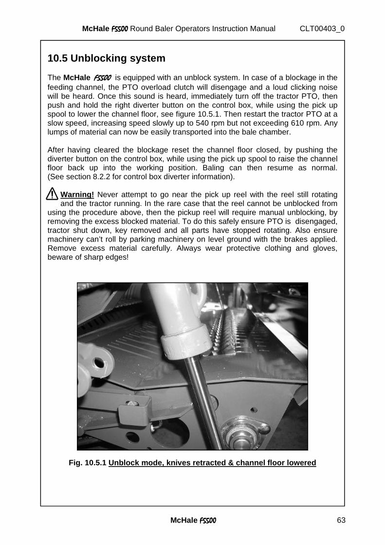
McHale F5500F5500F5500F5500 63
McHale F5500F5500F5500F5500 Round Baler Operators Instruction Manual CLT00403_0
10.5 Unblocking system The McHale F5500F5500F5500F5500 is equipped with an unblock system. In case of a blockage in the feeding channel, the PTO overload clutch will disengage and a loud clicking noise will be heard. Once this sound is heard, immediately turn off the tractor PTO, then push and hold the right diverter button on the control box, while using the pick up spool to lower the channel floor, see figure 10.5.1. Then restart the tractor PTO at a slow speed, increasing speed slowly up to 540 rpm but not exceeding 610 rpm. Any lumps of material can now be easily transported into the bale chamber. After having cleared the blockage reset the channel floor closed, by pushing the diverter button on the control box, while using the pick up spool to raise the channel floor back up into the working position. Baling can then resume as normal. (See section 8.2.2 for control box diverter information).
Warning! Never attempt to go near the pick up reel with the reel still rotating and the tractor running. In the rare case that the reel cannot be unblocked from
using the procedure above, then the pickup reel will require manual unblocking, by removing the excess blocked material. To do this safely ensure PTO is disengaged, tractor shut down, key removed and all parts have stopped rotating. Also ensure machinery can’t roll by parking machinery on level ground with the brakes applied. Remove excess material carefully. Always wear protective clothing and gloves, beware of sharp edges!
Fig. 10.5.1 Unblock mode, knives retracted & channel floor lowered
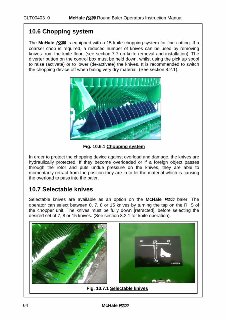
McHale F5500F5500F5500F5500 64
McHale F5500F5500F5500F5500 Round Baler Operators Instruction Manual CLT00403_0
Knife
10.6 Chopping system The McHale F5500F5500F5500F5500 is equipped with a 15 knife chopping system for fine cutting. If a coarser chop is required, a reduced number of knives can be used by removing knives from the knife floor, (see section 7.7 on knife removal and installation). The diverter button on the control box must be held down, whilst using the pick up spool to raise (activate) or to lower (de-activate) the knives. It is recommended to switch the chopping device off when baling very dry material. (See section 8.2.1).
Fig. 10.6.1 Chopping system
In order to protect the chopping device against overload and damage, the knives are hydraulically protected. If they become overloaded or if a foreign object passes through the rotor and puts undue pressure on the knives, they are able to momentarily retract from the position they are in to let the material which is causing the overload to pass into the baler.
10.7 Selectable knives Selectable knives are available as an option on the McHale F5500F5500F5500F5500 baler. The operator can select between 0, 7, 8 or 15 knives by turning the tap on the RHS of the chopper unit. The knives must be fully down [retracted], before selecting the desired set of 7, 8 or 15 knives. (See section 8.2.1 for knife operation).
Fig. 10.7.1 Selectable knives
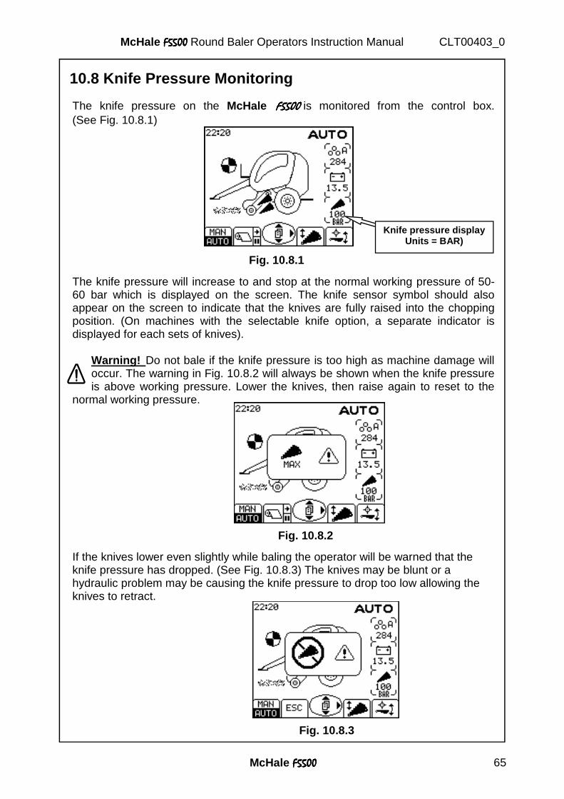
McHale F5500F5500F5500F5500 65
McHale F5500F5500F5500F5500 Round Baler Operators Instruction Manual CLT00403_0
The knife pressure on the McHale F5500F5500F5500F5500 is monitored from the control box. (See Fig. 10.8.1)
The knife pressure will increase to and stop at the normal working pressure of 50-60 bar which is displayed on the screen. The knife sensor symbol should also appear on the screen to indicate that the knives are fully raised into the chopping position. (On machines with the selectable knife option, a separate indicator is displayed for each sets of knives).
Warning! Do not bale if the knife pressure is too high as machine damage will occur. The warning in Fig. 10.8.2 will always be shown when the knife pressure is above working pressure. Lower the knives, then raise again to reset to the
normal working pressure. If the knives lower even slightly while baling the operator will be warned that the knife pressure has dropped. (See Fig. 10.8.3) The knives may be blunt or a hydraulic problem may be causing the knife pressure to drop too low allowing the knives to retract.
10.8 Knife Pressure Monitoring
Knife pressure display Units = BAR)
Fig. 10.8.1
Fig. 10.8.2
Fig. 10.8.3
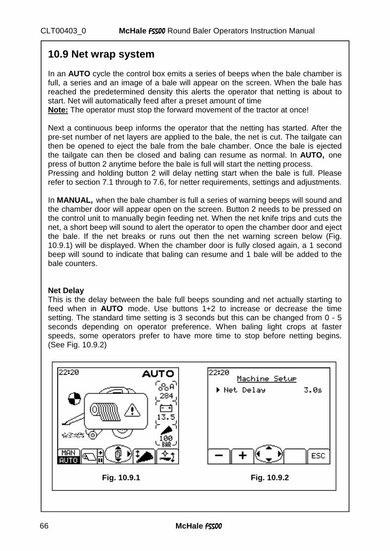
McHale F5500F5500F5500F5500 66
McHale F5500F5500F5500F5500 Round Baler Operators Instruction Manual CLT00403_0
10.9 Net wrap system In an AUTO cycle the control box emits a series of beeps when the bale chamber is full, a series and an image of a bale will appear on the screen. When the bale has reached the predetermined density this alerts the operator that netting is about to start. Net will automatically feed after a preset amount of time Note: The operator must stop the forward movement of the tractor at once! Next a continuous beep informs the operator that the netting has started. After the pre-set number of net layers are applied to the bale, the net is cut. The tailgate can then be opened to eject the bale from the bale chamber. Once the bale is ejected the tailgate can then be closed and baling can resume as normal. In AUTO, one press of button 2 anytime before the bale is full will start the netting process. Pressing and holding button 2 will delay netting start when the bale is full. Please refer to section 7.1 through to 7.6, for netter requirements, settings and adjustments. In MANUAL, when the bale chamber is full a series of warning beeps will sound and the chamber door will appear open on the screen. Button 2 needs to be pressed on the control unit to manually begin feeding net. When the net knife trips and cuts the net, a short beep will sound to alert the operator to open the chamber door and eject the bale. If the net breaks or runs out then the net warning screen below (Fig. 10.9.1) will be displayed. When the chamber door is fully closed again, a 1 second beep will sound to indicate that baling can resume and 1 bale will be added to the bale counters. Net Delay This is the delay between the bale full beeps sounding and net actually starting to feed when in AUTO mode. Use buttons 1+2 to increase or decrease the time setting. The standard time setting is 3 seconds but this can be changed from 0 - 5 seconds depending on operator preference. When baling light crops at faster speeds, some operators prefer to have more time to stop before netting begins. (See Fig. 10.9.2)
Fig. 10.9.1 Fig. 10.9.2
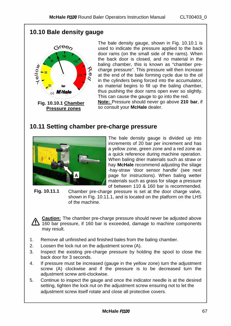
McHale F5500F5500F5500F5500 67
McHale F5500F5500F5500F5500 Round Baler Operators Instruction Manual CLT00403_0
10.10 Bale density gauge
10.11 Setting chamber pre-charge pressure
The bale density gauge is divided up into increments of 20 bar per increment and has a yellow zone, green zone and a red zone as a quick reference during machine operation. When baling drier materials such as straw or hay McHale recommend adjusting the silage-hay-straw ‘door sensor handle’ (see next page for instructions). When baling wetter materials such as grass for silage a pressure of between 110 & 160 bar is recommended.
Chamber pre-charge pressure is set at the door charge valve, shown in Fig. 10.11.1, and is located on the platform on the LHS of the machine.
Caution: The chamber pre-charge pressure should never be adjusted above 160 bar pressure, if 160 bar is exceeded, damage to machine components may result.
1. Remove all unfinished and finished bales from the baling chamber. 2. Loosen the lock nut on the adjustment screw (A). 3. Inspect the existing pre-charge pressure by holding the spool to close the
back door for 3 seconds. 4. If pressure must be increased (gauge in the yellow zone) turn the adjustment
screw (A) clockwise and if the pressure is to be decreased turn the adjustment screw anti-clockwise.
5. Continue to inspect the gauge and once the indicator needle is at the desired setting, tighten the lock nut on the adjustment screw ensuring not to let the
adjustment screw itself rotate and close all protective covers.
Fig. 10.10.1 Chamber Pressure zones
The bale density gauge, shown in Fig. 10.10.1 is used to indicate the pressure applied to the back door rams (on the small side of the rams). When the back door is closed, and no material in the baling chamber, this is known as “chamber pre-charge pressure”. This pressure will then increase at the end of the bale forming cycle due to the oil in the cylinders being forced into the accumulator, as material begins to fill up the baling chamber, thus pushing the door rams open ever so slightly. This can cause the gauge to go into the red. Note: Pressure should never go above 210 bar , if so consult your McHale dealer.
A
Fig. 10.11.1
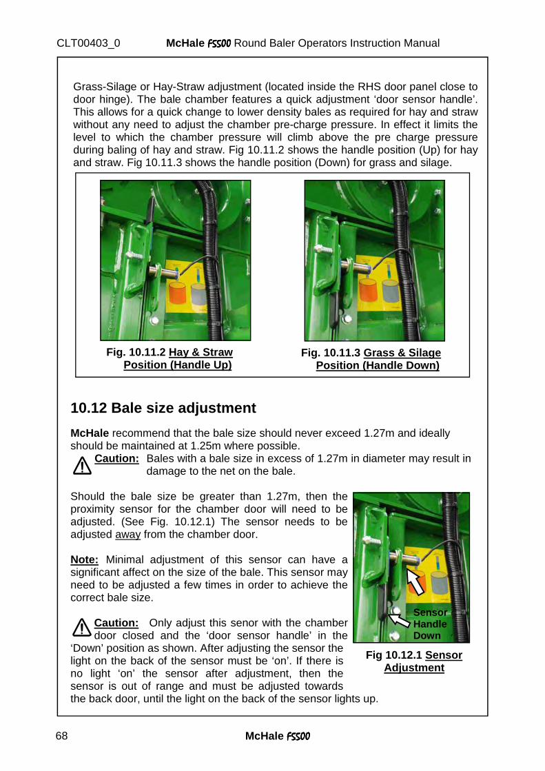
McHale F5500F5500F5500F5500 68
McHale F5500F5500F5500F5500 Round Baler Operators Instruction Manual CLT00403_0
Grass-Silage or Hay-Straw adjustment (located inside the RHS door panel close to door hinge). The bale chamber features a quick adjustment ‘door sensor handle’. This allows for a quick change to lower density bales as required for hay and straw without any need to adjust the chamber pre-charge pressure. In effect it limits the level to which the chamber pressure will climb above the pre charge pressure during baling of hay and straw. Fig 10.11.2 shows the handle position (Up) for hay and straw. Fig 10.11.3 shows the handle position (Down) for grass and silage.
10.12 Bale size adjustment McHale recommend that the bale size should never exceed 1.27m and ideally should be maintained at 1.25m where possible.
Caution: Bales with a bale size in excess of 1.27m in diameter may result in damage to the net on the bale.
Should the bale size be greater than 1.27m, then the proximity sensor for the chamber door will need to be adjusted. (See Fig. 10.12.1) The sensor needs to be adjusted away from the chamber door. Note: Minimal adjustment of this sensor can have a significant affect on the size of the bale. This sensor may need to be adjusted a few times in order to achieve the correct bale size.
Caution: Only adjust this senor with the chamber door closed and the ‘door sensor handle’ in the
‘Down’ position as shown. After adjusting the sensor the light on the back of the sensor must be ‘on’. If there is no light ‘on’ the sensor after adjustment, then the sensor is out of range and must be adjusted towards the back door, until the light on the back of the sensor lights up.
Fig. 10.11.2 Hay & Straw Position (Handle Up)
Fig. 10.11.3 Grass & Silage Position (Handle Down)
Fig 10.12.1 Sensor Adjustment
Sensor Handle Down
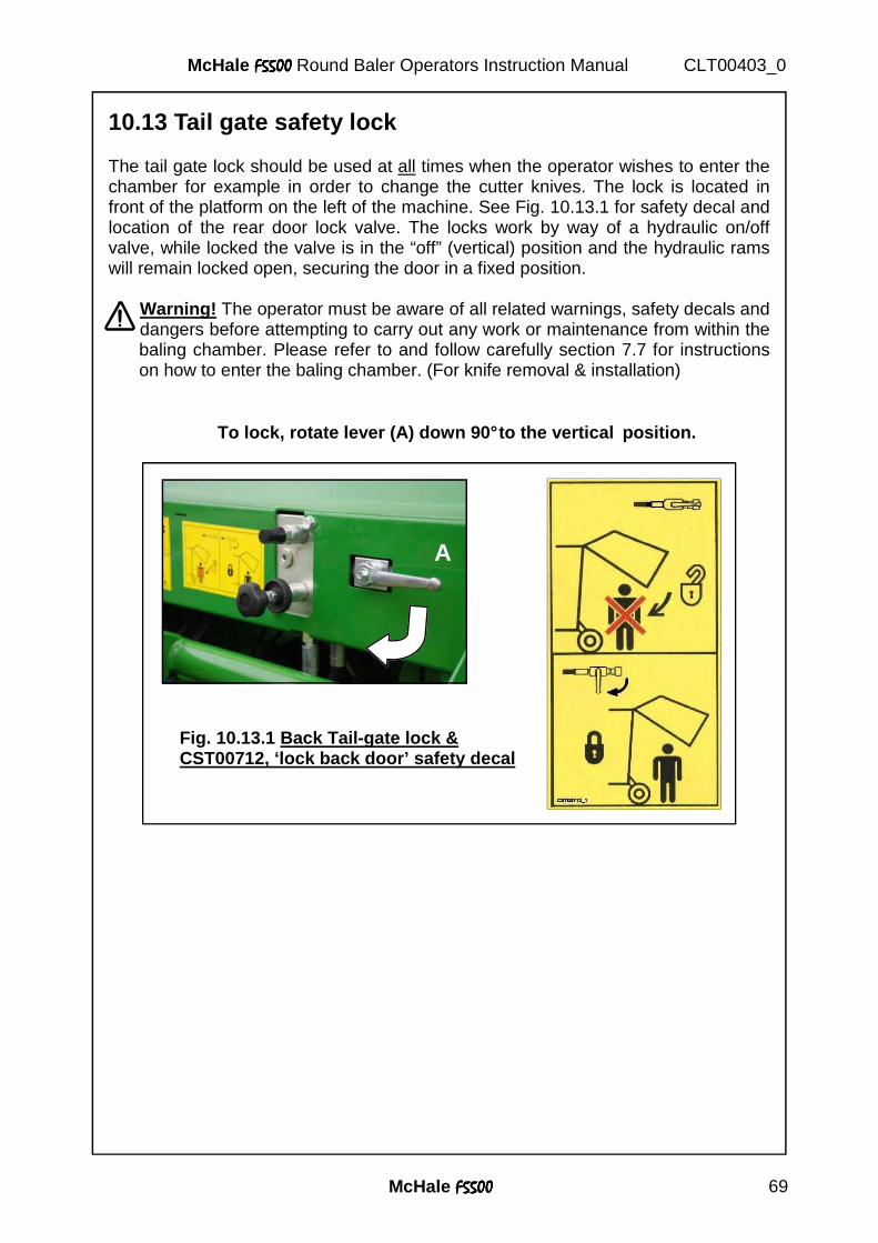
McHale F5500F5500F5500F5500 69
McHale F5500F5500F5500F5500 Round Baler Operators Instruction Manual CLT00403_0
10.13 Tail gate safety lock The tail gate lock should be used at all times when the operator wishes to enter the chamber for example in order to change the cutter knives. The lock is located in front of the platform on the left of the machine. See Fig. 10.13.1 for safety decal and location of the rear door lock valve. The locks work by way of a hydraulic on/off valve, while locked the valve is in the “off” (vertical) position and the hydraulic rams will remain locked open, securing the door in a fixed position.
Warning! The operator must be aware of all related warnings, safety decals and dangers before attempting to carry out any work or maintenance from within the baling chamber. Please refer to and follow carefully section 7.7 for instructions on how to enter the baling chamber. (For knife removal & installation)
To lock, rotate lever (A) down 90° to the vertical position.
A
Fig. 10.13.1 Back Tail-gate lock & CST00712, ‘lock back door’ safety decal
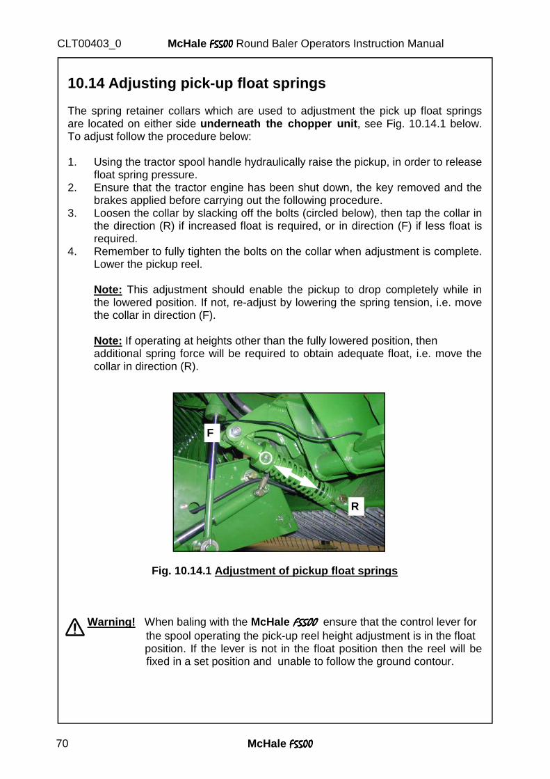
McHale F5500F5500F5500F5500 70
McHale F5500F5500F5500F5500 Round Baler Operators Instruction Manual CLT00403_0
10.14 Adjusting pick-up float springs The spring retainer collars which are used to adjustment the pick up float springs are located on either side underneath the chopper unit , see Fig. 10.14.1 below. To adjust follow the procedure below: 1. Using the tractor spool handle hydraulically raise the pickup, in order to release
float spring pressure. 2. Ensure that the tractor engine has been shut down, the key removed and the
brakes applied before carrying out the following procedure. 3. Loosen the collar by slacking off the bolts (circled below), then tap the collar in
the direction (R) if increased float is required, or in direction (F) if less float is required.
4. Remember to fully tighten the bolts on the collar when adjustment is complete. Lower the pickup reel.
Note: This adjustment should enable the pickup to drop completely while in the lowered position. If not, re-adjust by lowering the spring tension, i.e. move the collar in direction (F). Note: If operating at heights other than the fully lowered position, then additional spring force will be required to obtain adequate float, i.e. move the collar in direction (R).
Fig. 10.14.1 Adjustment of pickup float springs
Warning! When baling with the McHale F5500F5500F5500F5500 ensure that the control lever for the spool operating the pick-up reel height adjustment is in the float
position. If the lever is not in the float position then the reel will be fixed in a set position and unable to follow the ground contour.
F
R
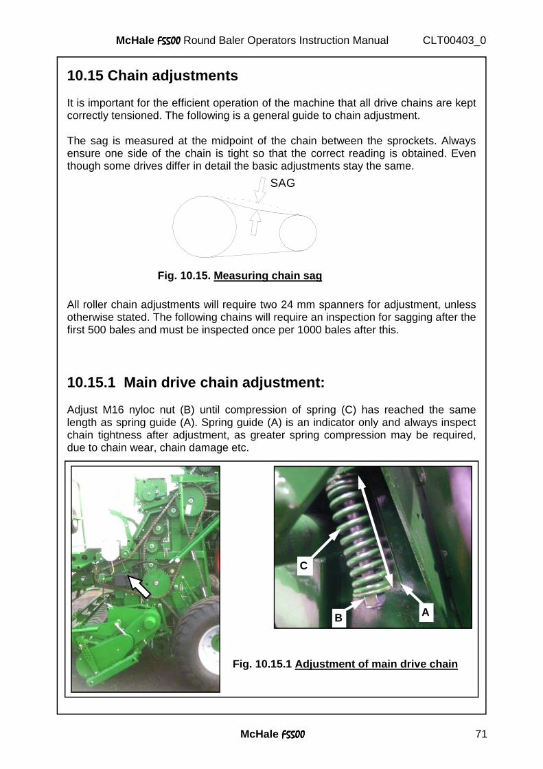
McHale F5500F5500F5500F5500 71
McHale F5500F5500F5500F5500 Round Baler Operators Instruction Manual CLT00403_0
10.15 Chain adjustments It is important for the efficient operation of the machine that all drive chains are kept correctly tensioned. The following is a general guide to chain adjustment. The sag is measured at the midpoint of the chain between the sprockets. Always ensure one side of the chain is tight so that the correct reading is obtained. Even though some drives differ in detail the basic adjustments stay the same. All roller chain adjustments will require two 24 mm spanners for adjustment, unless otherwise stated. The following chains will require an inspection for sagging after the first 500 bales and must be inspected once per 1000 bales after this.
10.15.1 Main drive chain adjustment: Adjust M16 nyloc nut (B) until compression of spring (C) has reached the same length as spring guide (A). Spring guide (A) is an indicator only and always inspect chain tightness after adjustment, as greater spring compression may be required, due to chain wear, chain damage etc.
SAG
Fig. 10.15. Measuring chain sag
Fig. 10.15.1 Adjustment of main drive chain
B
C
A
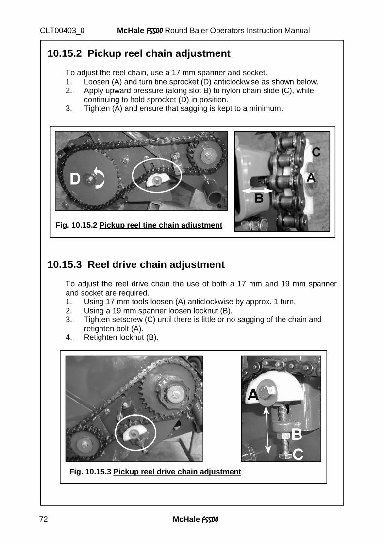
McHale F5500F5500F5500F5500 72
McHale F5500F5500F5500F5500 Round Baler Operators Instruction Manual CLT00403_0
10.15.2 Pickup reel chain adjustment To adjust the reel chain, use a 17 mm spanner and socket.
1. Loosen (A) and turn tine sprocket (D) anticlockwise as shown below. 2. Apply upward pressure (along slot B) to nylon chain slide (C), while continuing to hold sprocket (D) in position. 3. Tighten (A) and ensure that sagging is kept to a minimum.
10.15.3 Reel drive chain adjustment To adjust the reel drive chain the use of both a 17 mm and 19 mm spanner and socket are required.
1. Using 17 mm tools loosen (A) anticlockwise by approx. 1 turn. 2. Using a 19 mm spanner loosen locknut (B). 3. Tighten setscrew (C) until there is little or no sagging of the chain and retighten bolt (A). 4. Retighten locknut (B).
Fig. 10.15.2 Pickup reel tine chain adjustment
Fig. 10.15.3 Pickup reel drive chain adjustment
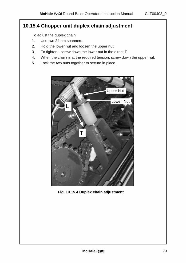
McHale F5500F5500F5500F5500 73
McHale F5500F5500F5500F5500 Round Baler Operators Instruction Manual CLT00403_0
10.15.4 Chopper unit duplex chain adjustment
To adjust the duplex chain
1. Use two 24mm spanners.
2. Hold the lower nut and loosen the upper nut.
3. To tighten - screw down the lower nut in the direct T.
4. When the chain is at the required tension, screw down the upper nut.
5. Lock the two nuts together to secure in place.
Fig. 10.15.4 Duplex chain adjustment
T
L
Upper Nut
Lower Nut
McHale F5500F5500F5500F5500 74
McHale F5500F5500F5500F5500 Round Baler Operators Instruction Manual CLT00403_0
11. Accessories and Optional Equipment
11.1 Accessory and optional equipment available Certain accessories and optional equipment may or may not be available in all countries, depending on varying circumstances. The following key symbols, are to aid in what equipment is sold as standard, optional and not available on the McHale F5500F5500F5500F5500. They are only correct at time of print and may vary.
Key: Standard Equipment = � Optional Equipment = �
11.2 Wheel chocks � Wheel chocks are provided to secure the baler wheels anytime the baler is to be detached from the tractor, or if the machine is to be stored or parked up. They are located on both the LHS and RHS of the back panels on the tailgate of the machine.
11.3 Drawbar hitch options � Low drawbar hitch � Depending on the country of use this drawbar type is standard but the high drawbar hitch is available as an option. See 11.5 for available stands. � High drawbar hitch � Depending on the country of use this drawbar type is standard but the low drawbar hitch is available as an option. 11.4 Tyre options � Tyre type A � Vredestein 500/50 - 17 [Flo +] (Part No: CWH00051) � Tyre type B � Vredestein 460/65 - 20 (Part No: CWH00083) � Tyre type C � BKT 500/50 - 22.5 (Part No: CWH00058) � Tyre type D � Vredestein 560/45 R22.5 [Flo Pro] (Part No: CWH00077)
Standard Equipment = � Optional Equipment = �
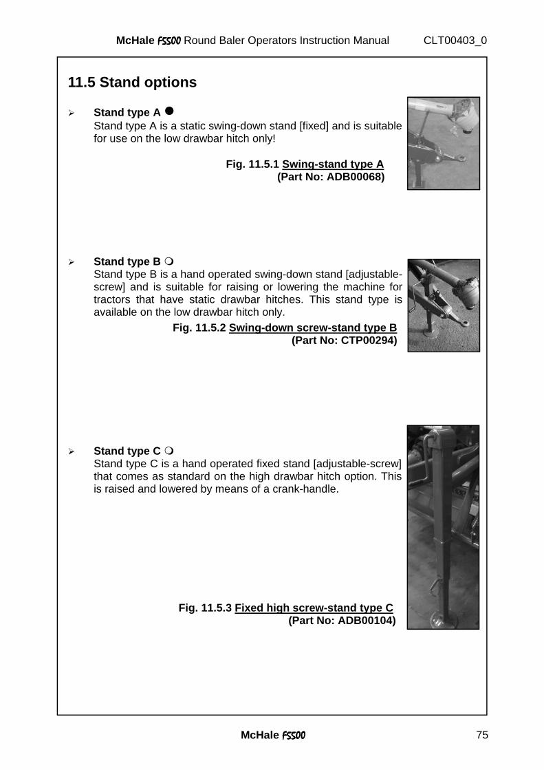
McHale F5500F5500F5500F5500 75
McHale F5500F5500F5500F5500 Round Baler Operators Instruction Manual CLT00403_0
11.5 Stand options � Stand type A � Stand type A is a static swing-down stand [fixed] and is suitable for use on the low drawbar hitch only!
� Stand type B � Stand type B is a hand operated swing-down stand [adjustable- screw] and is suitable for raising or lowering the machine for tractors that have static drawbar hitches. This stand type is available on the low drawbar hitch only. � Stand type C � Stand type C is a hand operated fixed stand [adjustable-screw] that comes as standard on the high drawbar hitch option. This is raised and lowered by means of a crank-handle.
Fig. 11.5.1 Swing-stand type A (Part No: ADB00068)
Fig. 11.5.2 Swing-down screw-stand type B (Part No: CTP00294)
Fig. 11.5.3 Fixed high screw-stand type C (Part No: ADB00104)
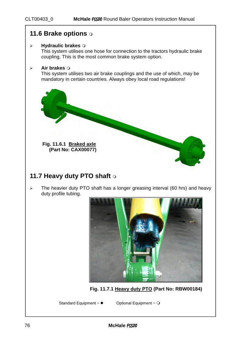
McHale F5500F5500F5500F5500 76
McHale F5500F5500F5500F5500 Round Baler Operators Instruction Manual CLT00403_0
11.6 Brake options � � Hydraulic brakes � This system utilises one hose for connection to the tractors hydraulic brake coupling. This is the most common brake system option. � Air brakes � This system utilises two air brake couplings and the use of which, may be mandatory in certain countries. Always obey local road regulations!
Standard Equipment = � Optional Equipment = �
Fig. 11.6.1 Braked axle (Part No: CAX00077)
11.7 Heavy duty PTO shaft � � The heavier duty PTO shaft has a longer greasing interval (60 hrs) and heavy
duty profile tubing.
Fig. 11.7.1 Heavy duty PTO (Part No: RBW00184)
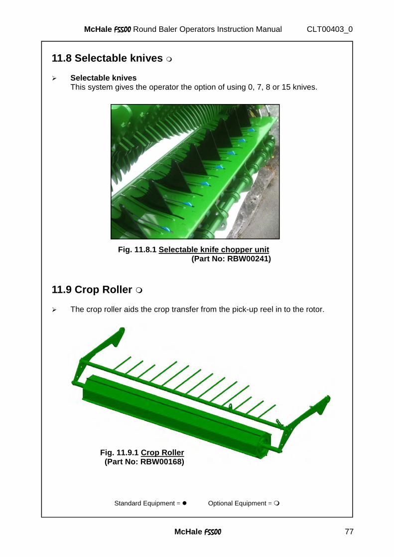
McHale F5500F5500F5500F5500 77
McHale F5500F5500F5500F5500 Round Baler Operators Instruction Manual CLT00403_0
11.8 Selectable knives � � Selectable knives This system gives the operator the option of using 0, 7, 8 or 15 knives.
11.9 Crop Roller � � The crop roller aids the crop transfer from the pick-up reel in to the rotor.
Fig. 11.8.1 Selectable knife chopper unit (Part No: RBW00241)
Fig. 11.9.1 Crop Roller (Part No: RBW00168)
Standard Equipment = � Optional Equipment = �
McHale F5500F5500F5500F5500 78
McHale F5500F5500F5500F5500 Round Baler Operators Instruction Manual CLT00403_0
12. Machine Maintenance
To maintain the McHale F5500 F5500 F5500 F5500 in good working order it is necessary to carry out preventative maintenance regularly. The following section gives details of how this may be carried out and how often it will be required.
Caution: It is vitally important to observe health and safety rules where necessary to avoid unnecessary environmental damage or danger to anybody near the machine. This especially applies to the responsible disposal of oil, etc.
12.1 Maintenance intervals The following intervals should be adhered to, in order to ensure a long and efficient life for the machine and maximum safety of personnel. They assume constant working during the harvesting season. 1) First 5 working hours:
� Check all nuts and bolts for tightness and tighten if necessary. � Check and correct, if necessary, the air pressure in the tyres. � Drain and change gearbox oil, please refer to section 7.9. � Carry out adjustment of chopper unit duplex chain, please refer to section 10.15.4. Inspect all other chains.
2) Every day (250 bales):
� Check wheel nuts. � Check all guards and safety devices. � Check road traffic equipment. � Check for any oil leaks or damaged pipes. � Grease 3x heavy duty grease-points on PTO shaft. � Fill chain lubrication reservoir. � Replace grease cartridge. � Grease chamber pivot points. � Check all chain adjustments, and adjust as necessary.
3) Every week: � Check for correct air pressure in the tyres. � Grease 5x standard duty grease-points on PTO shaft. � Check the belt tension on the netter unit (Section 7.6)
4) Every month: � Grease pick-up reel shaft bearings. � Grease pick-up cam clutch. � Check for sufficient oil level in the gear box.
5) Every year: � Clean and lubricate all moving parts of the net tying unit. � Drain and change gearbox oil, please refer to section 7.9.
McHale F5500F5500F5500F5500 79
McHale F5500F5500F5500F5500 Round Baler Operators Instruction Manual CLT00403_0
At the end of the baling season the machine should be washed and cleaned. Any damaged paintwork should be touched up. Any maintenance or repairs should be carried out at this stage. The electronic control box is not waterproof so it must always be stored in a dry environment. All exposed hydraulic cylinder rods should be greased. The pick-up and the cutting device area as well as the bale chamber should be cleaned and lubricated, see section 13.
Warning! Ensure to wear proper safety equipment at all times when working with the machine, such as gloves, eye protection etc. and follow all safety decals and instructions as stated in this manual.
McHale recommend that nobody ever be in the danger zone at any time during machine operation. In the event of carrying out inspections (contrary to our safety recommendations ) when the machine is in operation, there must always be a second operator at the tractor controls (who is fully competent in the operation of both the tractor and the machine), in case an emergency stop action is required.
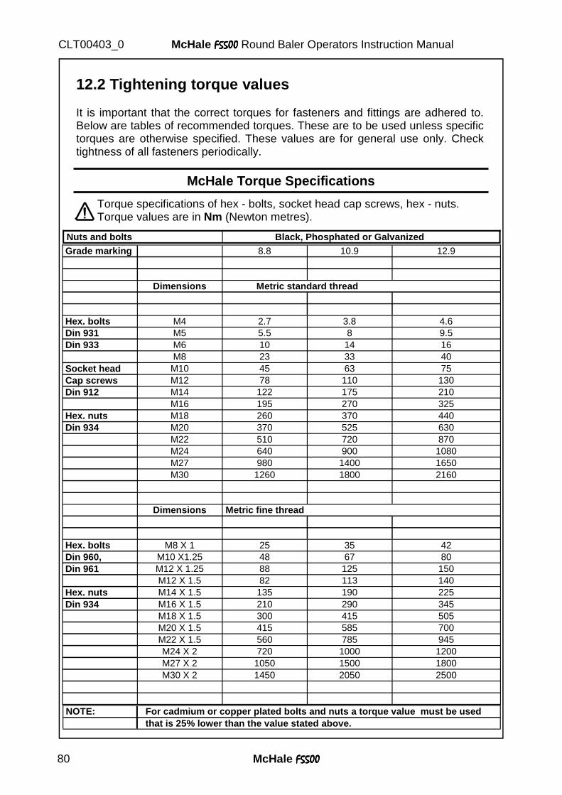
McHale F5500F5500F5500F5500 80
McHale F5500F5500F5500F5500 Round Baler Operators Instruction Manual CLT00403_0
12.2 Tightening torque values It is important that the correct torques for fasteners and fittings are adhered to. Below are tables of recommended torques. These are to be used unless specific torques are otherwise specified. These values are for general use only. Check tightness of all fasteners periodically.
Torque specifications of hex - bolts, socket head cap screws, hex - nuts. Torque values are in Nm (Newton metres).
McHale Torque Specifications
Grade marking 8.8 10.9 12.9
Dimensions
Hex. bolts M4 2.7 3.8 4.6 Din 931 M5 5.5 8 9.5 Din 933 M6 10 14 16
M8 23 33 40 Socket head M10 45 63 75 Cap screws M12 78 110 130 Din 912 M14 122 175 210
M16 195 270 325 Hex. nuts M18 260 370 440 Din 934 M20 370 525 630
M22 510 720 870 M24 640 900 1080 M27 980 1400 1650 M30 1260 1800 2160 Dimensions Metric fine thread
Hex. bolts M8 X 1 25 35 42 Din 960, M10 X1.25 48 67 80 Din 961 M12 X 1.25 88 125 150
M12 X 1.5 82 113 140 Hex. nuts M14 X 1.5 135 190 225 Din 934 M16 X 1.5 210 290 345
M18 X 1.5 300 415 505 M20 X 1.5 415 585 700 M22 X 1.5 560 785 945 M24 X 2 720 1000 1200 M27 X 2 1050 1500 1800 M30 X 2 1450 2050 2500
Metric standard thread
Nuts and bolts Black, Phosphated or Galvanized
NOTE: For cadmium or copper plated bolts and nuts a torque value must be used that is 25% lower than the value stated above.
McHale F5500F5500F5500F5500 81
McHale F5500F5500F5500F5500 Round Baler Operators Instruction Manual CLT00403_0
13. Storage
13.1 End of season � Carefully clean the baler sections inside and out. Dirt and foreign objects are
likely to draw moisture and cause rusting of steel components. Note: In the case of using a high pressure washer, do not point pressurized water at or near electrical components, pivot points, valves or bearings. McHale recommend that the machine be blown down with an air line as opposed to a pressure washer in order to protect the overall paint work on the machine.
� Remove control box from tractor and store in a dry, safe environment. � Clean the Net wrapping system as described in section 7.3. Remove net roll
and store as per manufacturers instructions. Grease the net knife to prevent rusting, use extreme caution when carrying out this operation, ensure to wear protective gloves and clothing!
� Lubricate all pivot points, apply a thin layer of grease to all adjustment bolt threads and exposed ram rods.
� Check all oil and grease lines for damage and repair them if required. � Any components from which paint has become worn should be touched up or
coated with grease to prevent rusting. � Remove all dirt from all chains and blow dry using compressed air. � Fill chain oil reservoir with chain oil & fit new grease cartridge, run PTO at
approx 200 rpm and operate the tailgate up & down for around 15 cycles to ensure that all chains have a heavy coating of oil applied, and new grease is pumped into the bearings. � Remove the knives from the chopping unit to prevent them from sticking and
store them in the spare knife holder.
13.2 Start of season preparation � Fully review this operators manual. � Check and fill gear box oil level if necessary, see section 7.9. � Lubricate all pivot points. � Tighten all bolts, nuts and setscrews, refer to section 12.2 for tightening torque
values. � Check air pressure of all tyres, refer to section 14.4. � Connect control box and inspect for correct operation of all functions, see section 8. � Inspect and modify, if necessary, all machine adjustments as per section 10. � Check net wrapping adjustments and inspect net knife for sharpness, ensure
to wear protective clothing whenever working in this area. � Remove the grease from the net cutting knife.
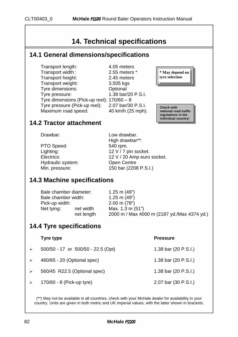
McHale F5500F5500F5500F5500 82
McHale F5500F5500F5500F5500 Round Baler Operators Instruction Manual CLT00403_0
14. Technical specifications
14.1 General dimensions/specifications Transport length: 4.05 meters Transport width : 2.55 meters * Transport height: 2.45 meters Transport weight: 3,505 kgs Tyre dimensions: Optional Tyre pressure: 1.38 bar/20 P.S.I. Tyre dimensions (Pick-up reel): 170/60 – 8 Tyre pressure (Pick-up reel): 2.07 bar/30 P.S.I. Maximum road speed: 40 km/h (25 mph).
14.2 Tractor attachment Drawbar: Low drawbar. High drawbar**. PTO Speed: 540 rpm. Lighting: 12 V / 7 pin socket. Electrics: 12 V / 20 Amp euro socket. Hydraulic system: Open Centre Min. pressure: 150 bar (2208 P.S.I.)
14.3 Machine specifications Bale chamber diameter: 1.25 m (49”) Bale chamber width: 1.25 m (49”) Pick-up width: 2.00 m (78”) Net tying: net width Max. 1.3 m (51”) net length 2000 m / Max 4000 m (2187 yd./Max 4374 yd.)
14.4 Tyre specifications Tyre type Pressure
� 500/50 - 17 or 500/50 - 22.5 (Opt) 1.38 bar (20 P.S.I.) � 460/65 - 20 (Optional spec) 1.38 bar (20 P.S.I.) � 560/45 R22.5 (Optional spec) 1.38 bar (20 P.S.I.) � 170/60 - 8 (Pick-up tyre) 2.07 bar (30 P.S.I.)
(**) May not be available in all countries, check with your McHale dealer for availability in your country. Units are given in both metric and UK imperial values, with the latter shown in brackets.
Check with nat ional road traffic regulations in the individual country!
Check with nat ional road traffic regulations in the individual country!
* May depend on tyre selection
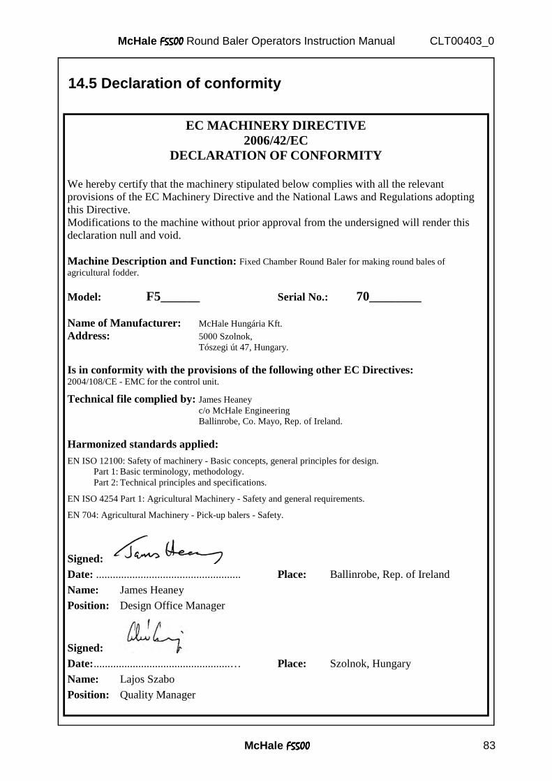
McHale F5500F5500F5500F5500 83
McHale F5500F5500F5500F5500 Round Baler Operators Instruction Manual CLT00403_0
14.5 Declaration of conformity
EC MACHINERY DIRECTIVE 2006/42/EC
DECLARATION OF CONFORMITY
We hereby certify that the machinery stipulated below complies with all the relevant provisions of the EC Machinery Directive and the National Laws and Regulations adopting this Directive. Modifications to the machine without prior approval from the undersigned will render this declaration null and void. Machine Description and Function: Fixed Chamber Round Baler for making round bales of agricultural fodder.
Model: F5______ Serial No.: 70________ Name of Manufacturer: McHale Hungária Kft. Address: 5000 Szolnok, Tószegi út 47, Hungary. Is in conformity with the provisions of the following other EC Directives: 2004/108/CE - EMC for the control unit.
Technical file complied by: James Heaney c/o McHale Engineering Ballinrobe, Co. Mayo, Rep. of Ireland.
Harmonized standards applied: EN ISO 12100: Safety of machinery - Basic concepts, general principles for design. Part 1: Basic terminology, methodology. Part 2: Technical principles and specifications.
EN ISO 4254 Part 1: Agricultural Machinery - Safety and general requirements.
EN 704: Agricultural Machinery - Pick-up balers - Safety.
Signed: Date: .................................................... Place: Ballinrobe, Rep. of Ireland
Name: James Heaney
Position: Design Office Manager
Signed: Date: .................................................… Place: Szolnok, Hungary
Name: Lajos Szabo
Position: Quality Manager
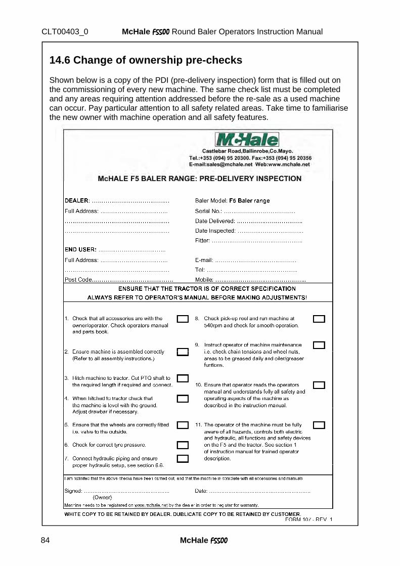
McHale F5500F5500F5500F5500 84
McHale F5500F5500F5500F5500 Round Baler Operators Instruction Manual CLT00403_0
14.6 Change of ownership pre-checks Shown below is a copy of the PDI (pre-delivery inspection) form that is filled out on the commissioning of every new machine. The same check list must be completed and any areas requiring attention addressed before the re-sale as a used machine can occur. Pay particular attention to all safety related areas. Take time to familiarise the new owner with machine operation and all safety features.
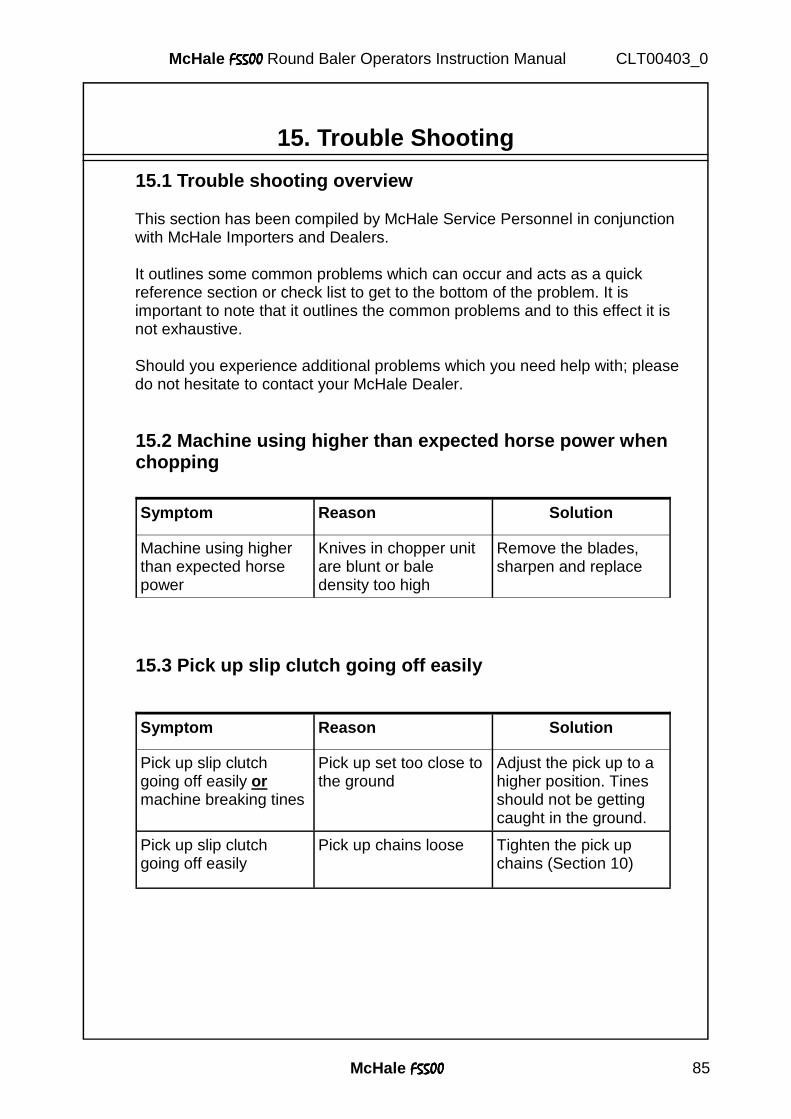
McHale F5500F5500F5500F5500 85
McHale F5500F5500F5500F5500 Round Baler Operators Instruction Manual CLT00403_0
15. Trouble Shooting 15.1 Trouble shooting overview
This section has been compiled by McHale Service Personnel in conjunction with McHale Importers and Dealers. It outlines some common problems which can occur and acts as a quick reference section or check list to get to the bottom of the problem. It is important to note that it outlines the common problems and to this effect it is not exhaustive. Should you experience additional problems which you need help with; please do not hesitate to contact your McHale Dealer.
15.2 Machine using higher than expected horse power when chopping
15.3 Pick up slip clutch going off easily
Symptom Reason Solution
Machine using higher than expected horse power
Knives in chopper unit are blunt or bale density too high
Remove the blades, sharpen and replace
Symptom Reason Solution
Pick up slip clutch going off easily or machine breaking tines
Pick up set too close to the ground
Adjust the pick up to a higher position. Tines should not be getting caught in the ground.
Pick up slip clutch going off easily
Pick up chains loose Tighten the pick up chains (Section 10)
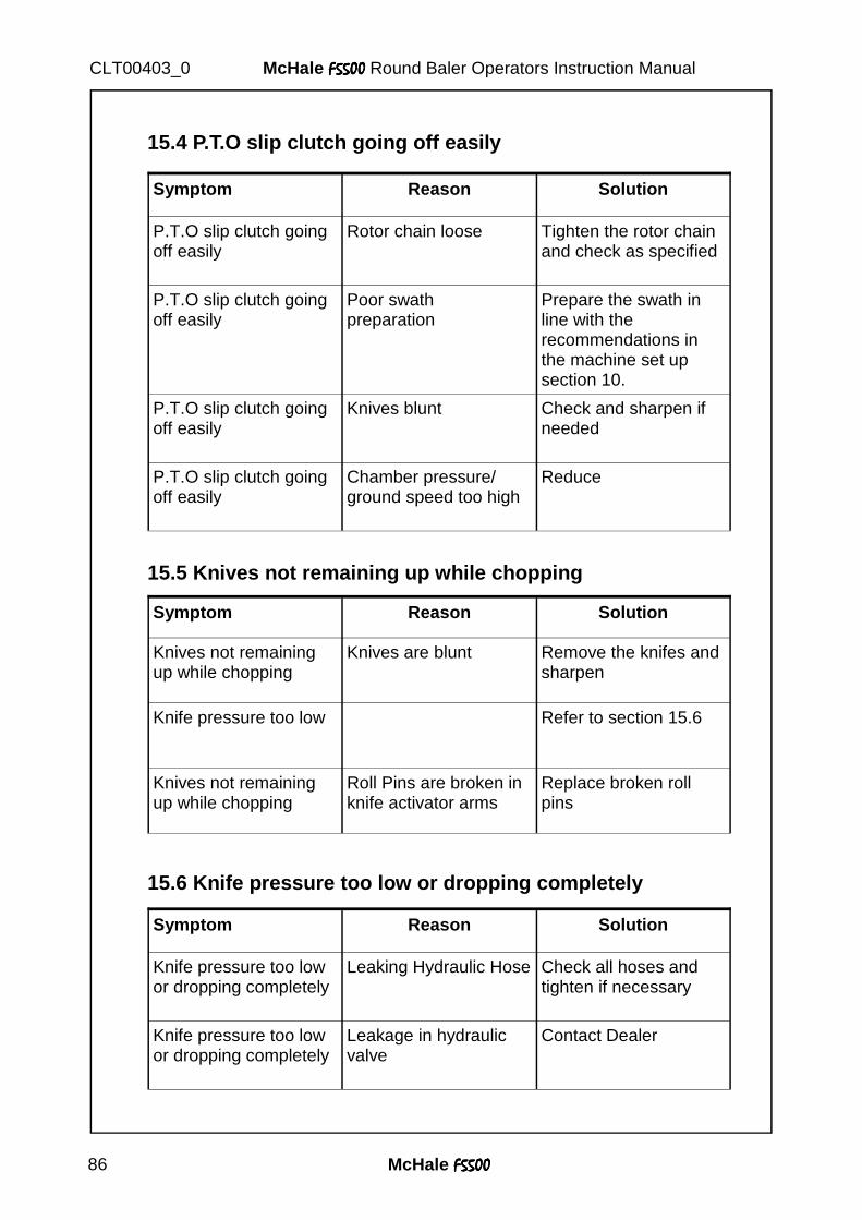
McHale F5500F5500F5500F5500 86
McHale F5500F5500F5500F5500 Round Baler Operators Instruction Manual CLT00403_0
15.4 P.T.O slip clutch going off easily
15.5 Knives not remaining up while chopping
15.6 Knife pressure too low or dropping completely
Symptom Reason Solution
P.T.O slip clutch going off easily
Rotor chain loose Tighten the rotor chain and check as specified
P.T.O slip clutch going off easily
Poor swath preparation
Prepare the swath in line with the recommendations in the machine set up section 10.
P.T.O slip clutch going off easily
Knives blunt Check and sharpen if needed
P.T.O slip clutch going off easily
Chamber pressure/ ground speed too high
Reduce
Symptom Reason Solution
Knives not remaining up while chopping
Knives are blunt Remove the knifes and sharpen
Knives not remaining up while chopping
Roll Pins are broken in knife activator arms
Replace broken roll pins
Knife pressure too low Refer to section 15.6
Symptom Reason Solution
Knife pressure too low or dropping completely
Leaking Hydraulic Hose Check all hoses and tighten if necessary
Knife pressure too low or dropping completely
Leakage in hydraulic valve
Contact Dealer
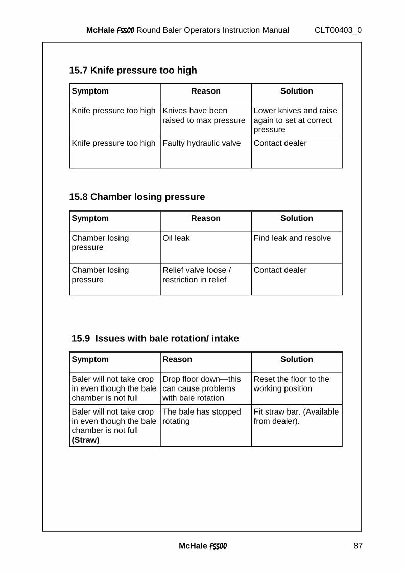
McHale F5500F5500F5500F5500 87
McHale F5500F5500F5500F5500 Round Baler Operators Instruction Manual CLT00403_0
15.7 Knife pressure too high
15.8 Chamber losing pressure
Symptom Reason Solution
Chamber losing pressure
Oil leak Find leak and resolve
Chamber losing pressure
Relief valve loose / restriction in relief
Contact dealer
Symptom Reason Solution
Knife pressure too high Knives have been raised to max pressure
Lower knives and raise again to set at correct pressure
Knife pressure too high Faulty hydraulic valve Contact dealer
15.9 Issues with bale rotation/ intake
Symptom Reason Solution
Baler will not take crop in even though the bale chamber is not full
Drop floor down—this can cause problems with bale rotation
Reset the floor to the working position
Baler will not take crop in even though the bale chamber is not full (Straw)
The bale has stopped rotating
Fit straw bar. (Available from dealer).
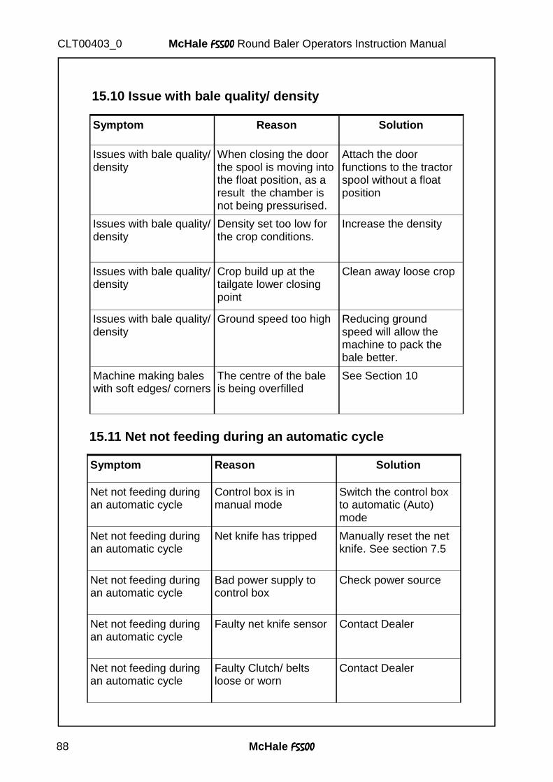
McHale F5500F5500F5500F5500 88
McHale F5500F5500F5500F5500 Round Baler Operators Instruction Manual CLT00403_0
15.11 Net not feeding during an automatic cycle
Symptom Reason Solution
Net not feeding during an automatic cycle
Control box is in manual mode
Switch the control box to automatic (Auto) mode
Net not feeding during an automatic cycle
Net knife has tripped Manually reset the net knife. See section 7.5
Net not feeding during an automatic cycle
Bad power supply to control box
Check power source
Net not feeding during an automatic cycle
Faulty net knife sensor Contact Dealer
Net not feeding during an automatic cycle
Faulty Clutch/ belts loose or worn
Contact Dealer
Symptom Reason Solution
Issues with bale quality/ density
When closing the door the spool is moving into the float position, as a result the chamber is not being pressurised.
Attach the door functions to the tractor spool without a float position
Issues with bale quality/ density
Density set too low for the crop conditions.
Increase the density
Issues with bale quality/ density
Crop build up at the tailgate lower closing point
Clean away loose crop
Issues with bale quality/ density
Ground speed too high Reducing ground speed will allow the machine to pack the bale better.
Machine making bales with soft edges/ corners
The centre of the bale is being overfilled
See Section 10
15.10 Issue with bale quality/ density
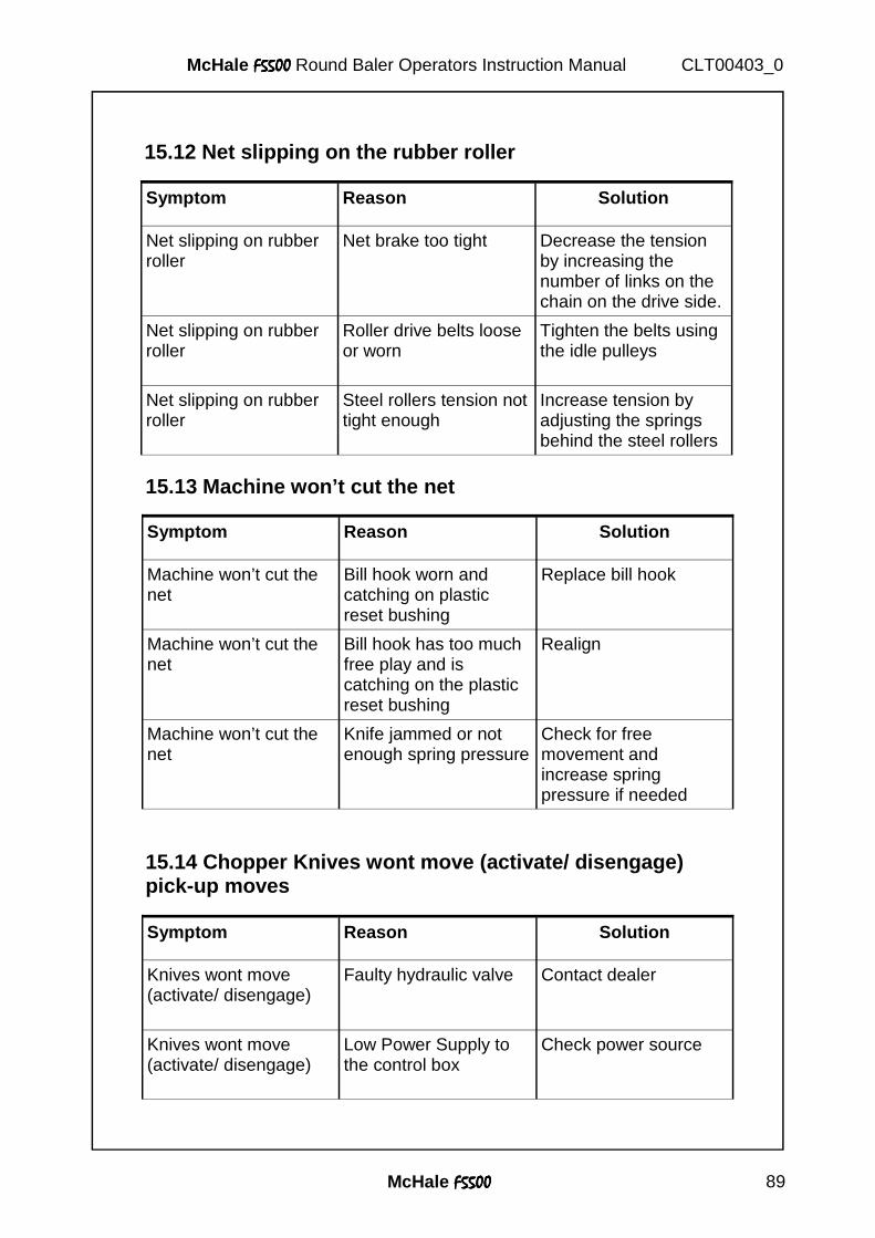
McHale F5500F5500F5500F5500 89
McHale F5500F5500F5500F5500 Round Baler Operators Instruction Manual CLT00403_0
Reason Solution Reference Section
Oil Leak Find Leak and resolve
Seals gone in door ram Test both rams and identify leaking ram and replace seals
Copper Washer inside door cartridge in door ram leaking
Remove cartridge and replace copper washer
Faulty Door Valve Replace Valve
15.12 Net slipping on the rubber roller
Symptom Reason Solution
Net slipping on rubber roller
Net brake too tight Decrease the tension by increasing the number of links on the chain on the drive side.
Net slipping on rubber roller
Roller drive belts loose or worn
Tighten the belts using the idle pulleys
Net slipping on rubber roller
Steel rollers tension not tight enough
Increase tension by adjusting the springs behind the steel rollers
15.13 Machine won’t cut the net
Symptom Reason Solution
Machine won’t cut the net
Bill hook worn and catching on plastic reset bushing
Replace bill hook
Machine won’t cut the net
Bill hook has too much free play and is catching on the plastic reset bushing
Realign
Machine won’t cut the net
Knife jammed or not enough spring pressure
Check for free movement and increase spring pressure if needed
15.14 Chopper Knives wont move (activate/ disengage) pick-up moves
Symptom Reason Solution
Knives wont move (activate/ disengage)
Faulty hydraulic valve Contact dealer
Knives wont move (activate/ disengage)
Low Power Supply to the control box
Check power source
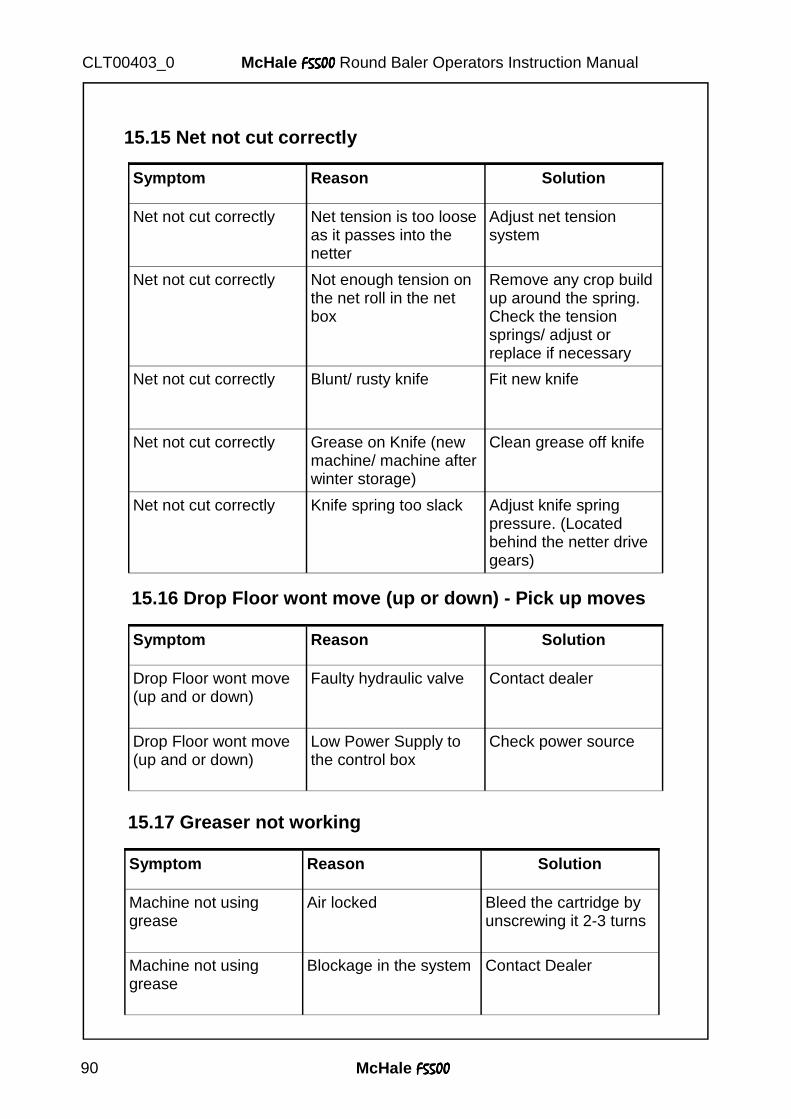
McHale F5500F5500F5500F5500 90
McHale F5500F5500F5500F5500 Round Baler Operators Instruction Manual CLT00403_0
Symptom Reason Solution
Net not cut correctly Net tension is too loose as it passes into the netter
Adjust net tension system
Net not cut correctly Not enough tension on the net roll in the net box
Remove any crop build up around the spring. Check the tension springs/ adjust or replace if necessary
Net not cut correctly Blunt/ rusty knife Fit new knife
Net not cut correctly Grease on Knife (new machine/ machine after winter storage)
Clean grease off knife
Net not cut correctly Knife spring too slack Adjust knife spring pressure. (Located behind the netter drive gears)
15.15 Net not cut correctly
15.16 Drop Floor wont move (up or down) - Pick up moves
Symptom Reason Solution
Drop Floor wont move (up and or down)
Faulty hydraulic valve Contact dealer
Drop Floor wont move (up and or down)
Low Power Supply to the control box
Check power source
15.17 Greaser not working
Symptom Reason Solution
Machine not using grease
Air locked Bleed the cartridge by unscrewing it 2-3 turns
Machine not using grease
Blockage in the system Contact Dealer
McHale F5500F5500F5500F5500 91
McHale F5500F5500F5500F5500 Round Baler Operators Instruction Manual CLT00403_0
16. Limited Warranty McHale Limited Warranty McHale Engineering, Ballinrobe, Co. Mayo, Ireland (hereinafter called “the company”) warrants to the original retail purchaser that new products sold and registered with the company, shall be, at the time of delivery, free from defects in material and workmanship, and that such equipment is covered under Limited Warranty provid-ing the machine is used and serviced in accordance with the recommendations in the Operator’s manual. This Limited Warranty covers the equipment for 10,000 bales, or a period of one year starting from the date the equipment is commissioned, whichever comes first. The online submission of the pre-delivery inspection (PDI) form by the dealer (Importer) is taken as evi-dence of the delivery of the machine to the original retail purchaser. This is compulsory, and is required to record the machine in the McHale warranty system.
� 1.1 These conditions are subject to the following exceptions; • Parts of the machine which are not of McHale manufacture, such as tyres, PTO shafts, slip
clutches, hydraulic cylinders, etc. are not covered by this limited warranty, but are subject to the warranty of the original manufacturer. Warranty claims applying to these types of parts must be submitted in the same way as if they were parts manufactured by McHale. However, compensation will be paid in accordance with the warranty agreement of the manufacturer concerned.
• This limited warranty does not apply to failure through normal wear and tear, to damage resulting from negligence or from lack of inspection, from misuse, from lack of maintenance and/or if the machine has been involved in an accident, lent out or used for purposes other than those for which it was intended by the company.
• This Limited Warranty will not apply to any product that has been altered or modified in any way without the express permission of the company, or if parts not approved by McHale are used in repair.
• The company take no responsibility for any additional costs, including loss of oil and/or consumables incurred during the failure and repair of a product
• The company cannot be held responsible for any claims or injuries to the owner or to the third party, nor to any resulting responsibility.
• Also, on no account can the company be held liable for incidental or consequential damages (including loss of anticipated profits) or for any impairment due to failure, a latent defect or a breakdown of a machine.
� 1.2 The customer will be responsible for the following costs;
• Normal maintenance such as greasing, maintenance of oil levels, minor adjustments, etc. as specified in the Operator’s manual.
• Labour charges other than originally agreed, incurred in the removal and replacement of components.
• Dealer’s travel time and travel costs to and from the machine. • Parts defined as normal wear items such as, but not limited to belts, blades, knives, tines, tine
bars, slip clutches, nylon chain runners and slides, etc. that are not covered under the Limited Warranty.
� 1.3 The importer will be responsible for the following costs; • All warranty labour charges.
McHale F5500F5500F5500F5500 92
McHale F5500F5500F5500F5500 Round Baler Operators Instruction Manual CLT00403_0
� 1.4 The limited Warranty is dependent on the strict observance of the following conditions: • The machine has been put in service by the dealer according to our instructions. • The online pre-delivery inspection (PDI) form has been correctly completed by the dealer. • A printed version of the PDI form has been signed and dated by the original retail purchaser. This copy is to be stored by the dealer and made available to McHale when
requested. • The warranty claim is submitted using the McHale online claims system. • The warranty claim must be submitted by the original retailing McHale dealer only. • The decision of the Company in all cases is final. • Damaged parts should be held by the dealer until credit has been given, or a returns request has been issued. • Parts must be returned to McHale with the McHale claim number written clearly on each
individual part. These parts must be free from dirt and oil. If a part is returned in an unfit state, the claim will be refused.
• If damaged parts have been returned to the company and warranty is refused, the dealer is allowed a period of one month from the date of receiving our notification to request the return of the damaged parts to the dealer site.
� 1.5 Further conditions: limits of application and responsibility
• This Limited Warranty cannot be assigned or transferred to anyone without the prior written consent of the Company. • McHale Dealers have no right or authority to assume any obligation or take any decision on
the Company's behalf, whether expressly or tacitly. • Technical assistance given by the company or its agents for repairing or operating equipment does not lead to any responsibility on the Company's behalf and cannot under any
circumstances bring novation or derogation to the conditions of the present Limited Warranty. • The Company reserves the right to incorporate changes in its machines without prior notice and without obligation to apply these changes to machines previously manufactured. • The present Limited Warranty excludes any other responsibility, whether legal or conventional, express or implied, and there are no warranties extending beyond those defined herein.