operation manual - new york state division of military...
TRANSCRIPT

2001, Mercury Marine 90-10229021 501
THIS MANUAL DESCRIBES THE SMARTCRAFT GAUGE
SYSTEMS AVAILABLE FOR YOUR BOAT
Operation Manual

0

MO
NIT
OR
1.0
1-1.
02
Par
t 1
Par
t 2
Par
t 3
Par
t 4
MO
NIT
OR
2.0
0S
YS
TE
M
TAC
H &
SP
EE
DS
MA
RT
TA
CH
& S
PE
ED
1
PRODUCT IDENTIFICATIONFor boats equipped with SmartCraft gauge systems, look tothe descriptions below to identify the system in the boat.Please read about the SmartCraft system to get the best per-formance from them.
MonitorSoftware Version 1.01 & 1.02
Part 1
NOTE: Software version willflash on screen at start up
MonitorSoftware Version 2.00
Part 2
NOTE: Software version willflash on screen at start up
System Tachometer and Speedometer
Part 3
Note: Look for RESETand Brightness arrows
Smart Tachometer and Speedometer
Part 4
NOTE: Look for letters “VDO”
VDO

2

MO
NIT
OR
1.0
1-1.
02
Part 1Monitor with Software Version1.01 and 1.02
Legend 1-1. . . . . . . . . . . . . . . . . . . . . . . . . . . . . . . . . . . . Basic Operation 1-2. . . . . . . . . . . . . . . . . . . . . . . . . . . . Standard Information Display Screens 1-3. . . . . . . . . Shallow Water Alarm 1-6. . . . . . . . . . . . . . . . . . . . . . . . Warning System 1-7. . . . . . . . . . . . . . . . . . . . . . . . . . . . Warning Display Screens 1-7. . . . . . . . . . . . . . . . . . . . CAL 1 Calibration 1-9. . . . . . . . . . . . . . . . . . . . . . . . . . . CAL 2 Calibration 1-12. . . . . . . . . . . . . . . . . . . . . . . . . .
NOTE:This manual shows all the Monitor displayscreens that are available. Depending on your typeof engine, not all these screens will apply.
Monitor with Software Version 1.01 and 1.02 iscompatible with:2001 model year and newer Mercury Outboard mod-els that are designed for use with SmartCraft.

MONITOR 1.01-1.02
1-0

A =
B =
C =
D =
E =
F =
I =
L =
N =
O =
P =
S =
T=
U=
= Engine
= Fuel
= Water Temperature
= Water Pressure
= Oil
= Alarm
MO
NIT
OR
1.0
1-1.
02
1-1
MONITOR – VERSION 1.01-1.02
Legend

MO
NIT
OR
1.0
1-1.
02
1-2
MONITOR – VERSION 1.01-1.02Basic OperationThis monitor is an LCD multi-function display gauge. A variety of dis-plays can be activated using the button.
Pressing the button scrolls the following displays: fuel used,tachometer (RPM), fuel flow, power trim position, engine temp, wa-ter pressure, battery voltage, range (if calibrated), and water depth(if equipped with transducer).
The System Monitor will power up when the ignition is turned on.
The display includes a backlight which allows you to read it at night.The backlight brightness is adjustable using button.
In the event of a warning alarm, the warning icon(s) will be displayed.

MO
NIT
OR
1.0
1-1.
02
1-3
MONITOR – VERSION 1.01-1.02Standard Information Display Screens
���
������ ��� �� ��� � �����
Initial Power Up At power up, a momentary (1second) screen displays thecurrent monitor software ver-sion, followed by a 4 second dis-play showing hours of engineuse.
��
Fuel UsedDisplays approximate fuel usedsince the last reset. Reset willreturn display back to 0.You can Reset anytime bypressing and buttons together momentarily.
��� Engine RPMTachometer – Displays enginespeed in Revolutions Per Min-ute (RPM).
����
Fuel FlowDisplays current estimated indi-vidual engine fuel consumptionin Gallons per hour (Gal/hr) orLiters per hour (Ltr/hr).

MO
NIT
OR
1.0
1-1.
02
1-4
MONITOR – VERSION 1.01-1.02Standard Information Display Screens
���� Trim PositionDisplays trim position of the pro-pulsion unit up to the maximumtrim position, and then displaysthe trailer position. 0 = down, 10 = full trim25 = full trailer.NOTE: This screen can be set topop up whenever the trim switchis used. Refer to the CAL 1 Cal-ibrations.
Engine TemperatureDisplays the engine tempera-ture in degrees Fahrenheit (°F)or Celsius (°C).
��
Water PressureDisplays the engine tempera-ture in degrees Fahrenheit (°F)or Celsius (°C).
����
Battery VoltageDisplays voltage level (condition)of battery.

MO
NIT
OR
1.0
1-1.
02
1-5
MONITOR – VERSION 1.01-1.02Standard Information Display Screens
� ��
��� RangeDisplays estimated rangebased on current fuel consump-tion and fuel remaining in thetank that is connected to thesystem. The number displayedis an estimate of the distanceyou can travel on the remainingfuel at current boat speed.NOTE: Two requirements to ac-tivate this screen, 1. you must perform the fueltank calibration in CAL 2. Referto the CAL 2 Calibrations Sec-tion.2. You must have a speed inputdevice connected to the system(paddle wheel or pitot pressuretransducer).
��
���� Water DepthDisplays the depth of water un-der the transducer if connected.
NOTE: You must have a depthtransducer connected to thesystem in order for this screen tooperate.

MO
NIT
OR
1.0
1-1.
02
1-6
MONITOR – VERSION 1.01-1.02Shallow Water AlarmYou can set an alarm to trigger whenever the boat moves into watershallower than the alarm level.
Setting Shallow Water Alarm.
1. The water depth screen must be displayed. Be sure Depth isturned on in CAL 2. Refer to CAL 2 Calibration Section.
2. Press both and buttons together for 3 seconds.
3. The alarm on or off menu will appear.
4. Press the button to toggle to ON.
����
5. Push button to save.
6. The depth number will be flashing. Press the button to setthe flashing number to desired alarm depth. 100 ft maximumdepth and 2 ft minimum depth.
����
7. Push button to save.

MO
NIT
OR
1.0
1-1.
02
1-7
MONITOR – VERSION 1.01-1.02Warning System
When a problem is detected with the engine, the warning displayscreens will alert the operator to the potential problem. Refer to theEngine Operation, Maintenance Manual for explanation of the prob-lem and the correct action to take.
If problem can cause immediate engine damage, the Engine GuardianSystem will respond to the problem by limiting engine power. Immedi-ately reduce throttle speed to idle. Refer to the Engine Operation,Maintenance Manual for further explanation of the problem and thecorrect action to take.
If the mode button is pressed to a different screen, the flashing alarmsignal will remain flashing to indicate there still is a problem.
Warning Display Screens
IMPORTANT: Refer to the Engine Operation, MaintenanceManual for further explanation of the problem and the correctaction to take.
Low Water PressureThe Bell and Water Pressureicons are displayed. There is in-sufficient water pressure in thecooling system.
Engine OverheatThe Bell and Temperature iconsare displayed There is insuffi-cient water pressure in the cool-ing system.
Low Oil ReserveThe bell and oil icons are dis-played. The oil level is criticallylow in the engine mounted oilreservoir tank.

MO
NIT
OR
1.0
1-1.
02
1-8
MONITOR – VERSION 1.01-1.02Warning Display ScreensIMPORTANT: Refer to the Engine Operation, MaintenanceManual for further explanation of the problem and the correctaction to take.
Oil Pump FaultThe Bell, Engine and oil iconsare displayed. The oil pump hasstopped functioning electrically.No lubricating oil is being sup-plied to the engine.
Water in FuelThe Bell and Fuel Icon are dis-played. Water in the water-sep-arating fuel filter reached the fulllevel.
Engine OverspeedThe Bell icon is displayed. Theengine speed exceeded themaximum allowable RPM.
Engine MalfunctionThe Bell and Engine Icon willappear to inform the driver thatan engine problem occurred.

MO
NIT
OR
1.0
1-1.
02
1-9
MONITOR – VERSION 1.01-1.02CAL 1 CalibrationCal 1 Display Calibrations:•Trim Pop up Screen (On or Off)•Trim Sensor Setting •English or Metric Readings Selection•Range Readings Selection•Fuel Tank Capacity Setting
1. Turn ignition key to the on position.
2. Press and hold and for 3 seconds to bring up theCAL 1 calibration screen.
NOTE:Press and hold and for 3 seconds to get out ofthe CAL 1 calibration screen.
Cal 1 Start Screen
Press the button to move to the next calibration screen.
��
�
Trim Pop-up Screen(Turn on or off)Select whether you want thepower trim display screen to popup whenever the trim switch isactivated.
1. Have the number “flashing” on display screen.
2. Press the button to select.1 = on0 = off
3. Press the button to move to the next function.
MO
NIT
OR
1.0
1-1.
02
1-10
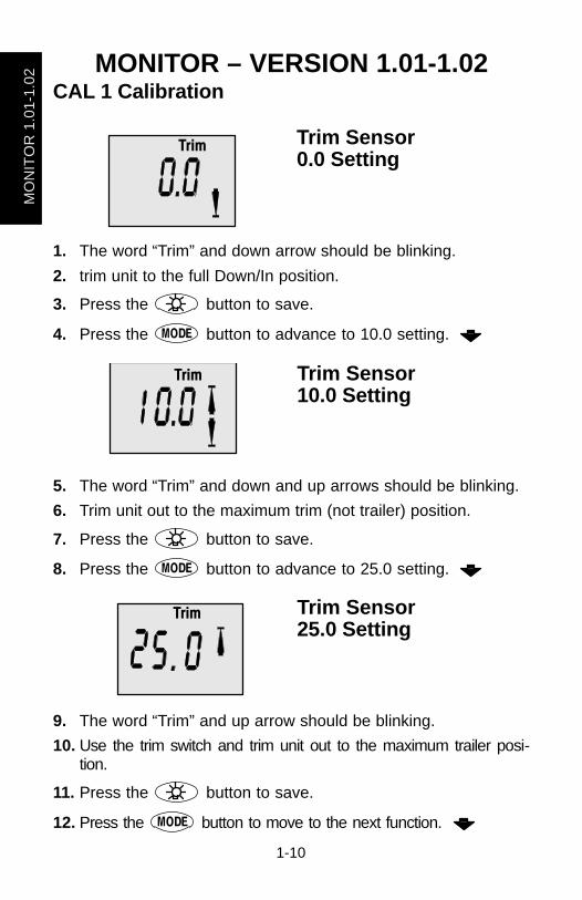
MONITOR – VERSION 1.01-1.02CAL 1 Calibration
�� � Trim Sensor 0.0 Setting
1. The word “Trim” and down arrow should be blinking.
2. trim unit to the full Down/In position.
3. Press the button to save.
4. Press the button to advance to 10.0 setting.
�� � Trim Sensor10.0 Setting
5. The word “Trim” and down and up arrows should be blinking.
6. Trim unit out to the maximum trim (not trailer) position.
7. Press the button to save.
8. Press the button to advance to 25.0 setting.
�� � Trim Sensor25.0 Setting
9. The word “Trim” and up arrow should be blinking.
10. Use the trim switch and trim unit out to the maximum trailer posi-tion.
11. Press the button to save.
12. Press the button to move to the next function.

MO
NIT
OR
1.0
1-1.
02
1-11
MONITOR – VERSION 1.01-1.02CAL 1 Calibration
����
��
�
SAE English System
��� �
�
!
Metric System English or MetricSelect whether you want thereadings in the SAE Englishsystem or the Metric system.
1. Press the button to toggle between units.
2. Press the button to move to the next function.
���
� ��
� ��
"�
#� ��
Range ReadingsSelect whether you want thereadings in Miles, Nautical Milesor Kilometers.
1. Press the button to toggle between units.
2. Press the button to move to the next function.
��
Fuel Tank CapacityIf the boat installation does nothave the fuel tank level sensorwired to the monitor, then cali-brate the fuel tank capacity set-ting to read 0.If a fuel tank level sensor iswired to the monitor, than enterthe capacity of the fuel tank thathas the sensor.
IMPORTANT: Set the fuel tank capacity setting at 0 if the fueltank level is not going to be calibrated. This will prevent aconstant alarm.
3. Press the button to input tank capacity number.
4. Press the button to move to the next function.

MO
NIT
OR
1.0
1-1.
02
1-12
MONITOR – VERSION 1.01-1.02CAL 2 CalibrationCal 2 Display Calibrations:•Single or Multi-engine InstallationSetting•Dual Station Setting •Paddle Wheel Speed SensorFrequency Setting•Pitot Water Pressure Sensor Input Setting
•Fuel Tank Calibration•Depth Screen (On or Off)•Coolant Screen (On or Off)•Oil Pressure Screen (On or Off)•Water Pressure Screen (On or Off)•Voltage Screen (On or Off)
1. Turn ignition key to the on position.
2. Press and hold and for 3 seconds to bring up the
CAL 1 calibration screen. Press and hold and againfor 3 seconds to bring up the CAL 2 calibration screen.
NOTE:Press and hold and for 3 seconds to get out ofthe CAL 2 calibration screen.
Cal 2 Start Screen
Press the button to move to the next calibration screen.
Single or Multi-EngineSettingThis screen lets you select theengine position that the Monitoris connected to.
Press the button to move to the next function.

MO
NIT
OR
1.0
1-1.
02
1-13
MONITOR – VERSION 1.01-1.02CAL 2 Calibration
Dual Station SettingIf you have 2 Monitorsconnected to the same engine,one can be set St1 and the othershould be St2.
Press the button to save and move to the next function.
� ��
Paddle Wheel SpeedSensor FrequencyFrequency can be changed tomatch requirements of differentsensors. 4.9 is the frequency ofthe paddle wheel speed sensorprovided by Mercury Marine.
Press the button to save and move to the next function.
Water Pressure SensorInputSelect the speed input of the Pi-tot water pressure sensor on theengine.NOTE:The standard speed in-put on production Mercury Out-boards is 100 PSI. On a HighPerformance Outboard it couldbe 200 Psi.
1. Press the button to select.1 = 100 PSI2 = 200 PSI
2. Press the button to move to the next function.

MO
NIT
OR
1.0
1-1.
02
1-14
MONITOR – VERSION 1.01-1.02CAL 2 Calibration
Fuel Tank CalibrationSelect whether you want to cali-brate the fuel tank. NOTE: Selecting “1” will contin-ue fuel tank calibration.
1. Press the button to select 1= on, 0 = off.
��
Fuel Tank Calibration0% SettingHave the fuel tank level atempty.
2. Press the button to save. Press the button to ad-
vance to 25% setting.
25 Percent Fuel to Add
��
Fuel Tank Calibration25% SettingAdding the amount of fuel shownwill raise fuel tank level to 25 per-cent.NOTE:The quantity of “Fuel toAdd” is determined by the fueltank capacity number entered inCAL 1
3. Add the displayed amount of fuel to the fuel tank.
4. Press the button to save. Press the button to ad-
vance to 50% setting.

MO
NIT
OR
1.0
1-1.
02
1-15
MONITOR – VERSION 1.01-1.02CAL 2 Calibration
50 Percent Fuel to Add
��
Fuel Tank Calibration50% SettingAdding the amount of fuel shownwill raise fuel tank level to 50 per-cent.NOTE:The quantity of “Fuel toAdd” is determined by the fueltank capacity number entered inCAL 1
5. Add the displayed amount of fuel to the fuel tank.
6. Press the button to save. Press the button to ad-
vance to 75% setting.
75 Percent Fuel to Add
��
Fuel Tank Calibration75% SettingAdding the amount of fuel shownwill raise fuel tank level to 75 per-cent.NOTE:The quantity of “Fuel toAdd” is determined by the fueltank capacity number entered inCAL 1
7. Add the displayed amount of fuel to the fuel tank.
8. Press the button to save. Press the button to ad-
vance to full% setting.
Full Percent Fuel to Add
��
Fuel Tank CalibrationFull SettingAdd the amount of fuel to fill thefuel tank.
9. Add the amount of fuel to fill the fuel tank.
10. Press the button to save. Press the button to ad-
vance to next function.

MO
NIT
OR
1.0
1-1.
02
1-16
MONITOR – VERSION 1.01-1.02CAL 2 Calibration
Depth Display (on oroff)Select whether you want thedepth screen to be displayed.
1. Press the button to select on or off.
2. Press the button to move to the next function.
Coolant TemperatureDisplay (on or off)Select whether you want thecoolant temperature screen tobe displayed.
1. Press the button to select on or off.
2. Press the button to move to the next function.
Oil Pressure Display(on or off)Select whether you want the oilpressure screen to be dis-played.
1. Press the button to select on or off.
2. Press the button to move to the next function.

MO
NIT
OR
1.0
1-1.
02
1-17
MONITOR – VERSION 1.01-1.02CAL 2 Calibration
Water Pressure Display(on or off)Select whether you want thewater pressure screen to be dis-played.
1. Press the button to select on or off.
2. Press the button to move to the next function.
����
Battery Voltage Display(on or off)Select whether you want thebattery voltage screen to be dis-played.
1. Press the button to select on or off.
2. Press and hold and for 3 seconds to get out of theCAL 2 calibration screen.


MO
NIT
OR
2.0
0
Part 2Monitor with Software Version2.00
Legend 2-1. . . . . . . . . . . . . . . . . . . . . . . . . . . . . . . . . . . . Basic Operation 2-2. . . . . . . . . . . . . . . . . . . . . . . . . . . . Initial Power Up 2-2. . . . . . . . . . . . . . . . . . . . . . . . . . . . Master Reset 2-4. . . . . . . . . . . . . . . . . . . . . . . . . . . . . . Standard Information Display Screens 2-5. . . . . . . . . Shallow Water Alarm 2-8. . . . . . . . . . . . . . . . . . . . . . . . Warning System 2-9. . . . . . . . . . . . . . . . . . . . . . . . . . . . Warning Display Screens 2-9. . . . . . . . . . . . . . . . . . . . CAL 1 Calibration 2-11. . . . . . . . . . . . . . . . . . . . . . . . . . CAL 2 Calibration 2-16. . . . . . . . . . . . . . . . . . . . . . . . . .
NOTE:This manual shows all the Monitor displayscreens that are available. Depending on your typeof engine, not all these screens will apply.
Monitor with Software Version 2.00 is compatiblewith:2002 model year and newer Mercury Outboard Mod-els that are designed for use with SmartCraft.MerCruiser model 8.1/496

MONITOR 2.00
2-0

MO
NIT
OR
2.0
0
2-1
MONITOR – VERSION 2.00Legend
A =
B =
C =
D =
E =
F =
I =
L =
N =
O =
P =
S =
T=
U=
= Engine
= Fuel
= Water Temperature
= Water Pressure
= Oil
= Alarm

MO
NIT
OR
2.0
0
2-2
MONITOR – VERSION 2.00Basic OperationThe Monitor is an LCD multi-function display gauge. A variety of dis-plays can be activated using the button.
Pressing the button scrolls the following displays: fuel used,tachometer (RPM), fuel flow, power trim position, engine temp, wa-ter pressure, battery voltage, range (if calibrated), and water depth(if equipped with transducer).
The Monitor will power up when the ignition is turned on.
The display includes a backlight which allows you to read it at night.The backlight brightness is adjustable using button.
In the event of a warning alarm, the warning icon(s) will be dis-played.
Initial Power Up (Or After Master Reset)Unit will display software level then flash the word “SEt” in conjunc-tion with engine icon.
Press the button.
AUTO-DETECTION
The unit will begin it’s “Auto-detection” of engine type procedure. Inthis procedure the Monitor checks with the engine control module(ECM) to see what type of engine you have and presets the data moni-toring screens accordingly, (e.g, If Monitor detects an inboard engineconnected to the data network it will turn off all engine/drive TRIM func-tions as these functions are not used in an inboard engine installation).The intention is to make initial setup easier.
(continued on next page)

MO
NIT
OR
2.0
0
2-3
MONITOR – VERSION 2.00Initial Power Up (Or After Master Reset)Initial Auto-Detection Error Messages:
Flashing “Stbd” – More than one ofthe engine computers (ECM’s) areconfigured as a starboard engine.The engines must be programmedfor proper engine location using aDDT or Quicksilver Diagnostic Tool.
Flashing “nonE” – The gauge doesnot see any engine computers(ECM’s). Please check wiring for badconnections and for proper amountof terminator resistors.
Flashing “noSt” – None of the en-gine computers (ECM’s) are config-ured as a starboard engine. En-gines may not be compatible ormust be programmed for proper en-gine location by using a DDT orQuicksilver Diagnostic Tool.
Flashing “2001” – You will need tomanually select your engine type.Use the button to scrollthrough the choices. Stnd = SternDrive, Inbd = Inboard, JEtd = JetDrive, Out2 = Outboard 2 Stroke,Out4 = Outboard 4 Stroke. Press to continue.

MO
NIT
OR
2.0
0
2-4
MONITOR – VERSION 2.00Master ResetYou can return the gauge back to factory presets through the MasterReset command.
IMPORTANT: Performing a master reset will reset the unit backto all factory defaults, thus eliminating any installation calibra-tions performed during set up of product.
1. Hold in and for approximately 12 seconds. You willsee the word “dFLt” let go of the buttons.
2. Immediately press and hold in and again until theunit counts down to zero “0”.
3. The “SEt” message flashing on the screen indicates that theunit has been reset to factory defaults.

MO
NIT
OR
2.0
0
2-5
MONITOR – VERSION 2.00Standard Information Display ScreensNOTE:This manual shows all the Monitor display screens that areavailable. Depending on your type of engine, not all these screenswill apply.
���
������ ��� �� ��� � �����
Start Up At start up, a momentary (1 sec-ond) screen displays the currentmonitor software version, fol-lowed by a 4 second displayshowing hours of engine use.
��
Fuel UsedDisplays approximate fuel usedsince the last reset. Reset willreturn display back to 0.You can Reset anytime bypressing and buttons together momentarily.
��� Engine RPMTachometer – Displays enginespeed in Revolutions Per Min-ute (RPM).
����
Fuel FlowDisplays current estimated indi-vidual engine fuel consumptionin Gallons per hour (Gal/hr) orLiters per hour (Ltr/hr).

MO
NIT
OR
2.0
0
2-6
MONITOR – VERSION 2.00Standard Information Display Screens
���� Trim PositionDisplays trim position of the pro-pulsion unit up to the maximumtrim position, and then displaysthe trailer position. 0 = down, 10 = full trim25 = full trailer.NOTE: This screen can be set topop up whenever the trim switchis used. Refer to the CAL 1 Cal-ibrations.
Engine TemperatureDisplays the engine tempera-ture in degrees Fahrenheit (°F)or Celsius (°C).
��
Water PressureDisplays the engine tempera-ture in degrees Fahrenheit (°F)or Celsius (°C).
Oil TemperatureDisplays the engine oil temperaturein degrees Fahrenheit (°F) or Cel-sius (°C).
MO
NIT
OR
2.0
0
2-7
MONITOR – VERSION 2.00Standard Information Display Screens
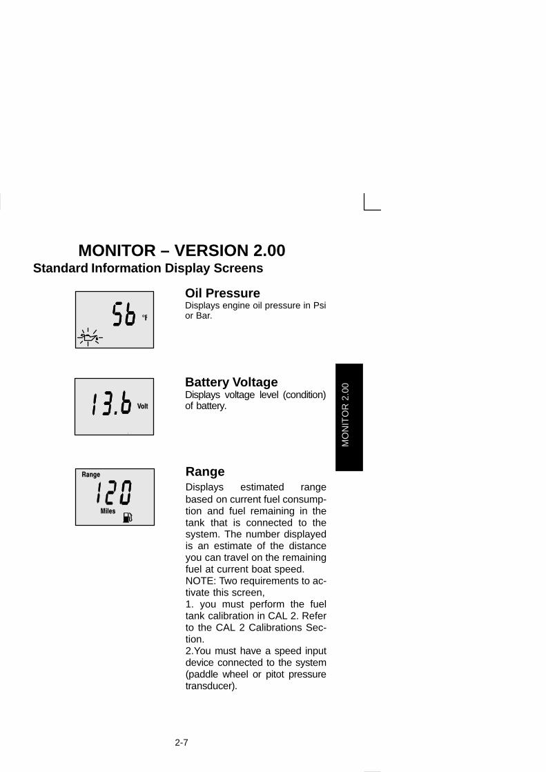
Oil PressureDisplays engine oil pressure in Psior Bar.
����
Battery VoltageDisplays voltage level (condition)of battery.
� ��
��� RangeDisplays estimated rangebased on current fuel consump-tion and fuel remaining in thetank that is connected to thesystem. The number displayedis an estimate of the distanceyou can travel on the remainingfuel at current boat speed.NOTE: Two requirements to ac-tivate this screen, 1. you must perform the fueltank calibration in CAL 2. Referto the CAL 2 Calibrations Sec-tion.2.You must have a speed inputdevice connected to the system(paddle wheel or pitot pressuretransducer).

MO
NIT
OR
2.0
0
2-8
MONITOR – VERSION 2.00Standard Information Display Screens
��
���� Water DepthDisplays the depth of water un-der the transducer if connected.
NOTE: You must have a depthtransducer (purchased separate-ly) connected to the system in or-der for this screen to operate.
Shallow Water AlarmYou can set an alarm to trigger whenever the boat moves into watershallower than the alarm level.
Setting Shallow Water Alarm.
1. The water depth screen must be displayed. Be sure Depth isturned on in CAL 2. Refer to CAL 2 Calibration Section.
2. Press both and buttons together for 3 seconds.
3. The alarm on or off menu will appear.
4. Press the button to toggle to ON.
����
5. Push button to save.
6. The depth number will be flashing. Press the button to setthe flashing number to desired alarm depth. 100 ft maximumdepth and 2 ft minimum depth.
����
7. Push button to save.

MO
NIT
OR
2.0
0
2-9
MONITOR – VERSION 2.00Warning System
When a problem is detected with the engine, the warning displayscreens will alert the operator to the potential problem. Refer to theEngine Operation, Maintenance Manual for explanation of the prob-lem and the correct action to take.
If problem can cause immediate engine damage, the Engine GuardianSystem will respond to the problem by limiting engine power. Immedi-ately reduce throttle speed to idle. Refer to the Engine Operation,Maintenance Manual for further explanation of the problem and thecorrect action to take.
If the mode button is pressed to a different screen, the flashing alarmsignal will remain flashing to indicate there still is a problem.
Warning Display Screens
IMPORTANT: Refer to the Engine Operation, MaintenanceManual for further explanation of the problem and the correctaction to take.
Engine OverheatThe Bell and Temperature iconsare displayed There is insuffi-cient water pressure in the cool-ing system.
Low Oil ReserveThe bell and oil icons are dis-played. The oil level is criticallylow in the engine mounted oilreservoir tank.
Low Water PressureThe Bell and Water Pressureicons are displayed. There is in-sufficient water pressure in thecooling system.

MO
NIT
OR
2.0
0
2-10
MONITOR – VERSION 2.00Warning Display ScreensIMPORTANT: Refer to the Engine Operation, MaintenanceManual for further explanation of the problem and the correctaction to take.
Water in FuelThe Bell and Fuel Icon are dis-played. Water in the water-sep-arating fuel filter reached the fulllevel.
Engine OverspeedThe Bell icon is displayed. Theengine speed exceeded themaximum allowable RPM.
Engine MalfunctionThe Bell and Engine Icon willappear to inform the driver thatan engine problem occurred.
Oil Pump FaultThe Bell, Engine and oil iconsare displayed. The oil pump hasstopped functioning electrically.No lubricating oil is being sup-plied to the engine.

MO
NIT
OR
2.0
0
2-11
MONITOR – VERSION 2.00CAL 1 CalibrationCal1 Display Calibrations:•(On or Off) Trim Pop up Screen•Trim Calibration•English or Metric Units Selection•Range Units Selection•(On or Off) Depth, Trim, Engine Temperature, Oil Pressure, OilTemperature, Water Pressure, Volts, Engine Hours, and DataSimulator pages.
1. Turn ignition key to the on position.
2. Press and hold and for 3 seconds to bring up theCAL 1 calibration screen.
NOTE:Press and hold and for 3 seconds to get out ofthe CAL 1 calibration screen.
Cal 1 Start Screen
Press the button to move to the next calibration screen.
��
�
Trim Pop-up Screen(Turn on or off)Select whether you want thepower trim display screen to popup whenever the trim switch isactivated.
1. Have the number “flashing” on display screen.
2. Press the button to select.1 = on0 = off
3. Press the button to move to the next function.

MO
NIT
OR
2.0
0
2-12
MONITOR – VERSION 2.00CAL 1 Calibration
�� � Trim Sensor 0.0 Setting
(Full Trim in Position)
1. The word “Trim” and down arrow should be blinking.
2. trim unit to the full Down/In position.
3. Press the button to save.
4. Press the button to advance to 10.0 setting.
�� � Trim Sensor10.0 Setting
(Full Trim Out Position)
5. The word “Trim” and down and up arrows should be blinking.
6. Trim unit out to the maximum trim (not trailer) position.
7. Press the button to save.
8. Press the button to advance to 25.0 setting.
�� � Trim Sensor25.0 Setting
(Full Trailer Out Position)
9. The word “Trim” and up arrow should be blinking.
10. Use the trim switch and trim unit out to the maximum trailer posi-tion.
11. Press the button to save.
12. Press the button to move to the next function.

MO
NIT
OR
2.0
0
2-13
MONITOR – VERSION 2.00CAL 1 Calibration
SAE English System
����
��
�
��� �
�
!
Metric System English or MetricSelect whether you want thereadings in the SAE Englishsystem or the Metric system.
1. Press the button to toggle between units.
2. Press the button to move to the next function.
� ��
"�
#� ��
���
� ��
Range ReadingsSelect whether you want thereadings in Miles, Nautical Milesor Kilometers.
1. Press the button to toggle between units.
2. Press the button to move to the next function.
Depth Display (on oroff)Select whether you want thedepth screen to be displayed.
1. Press the button to select on or off.
2. Press the button to move to the next function.
�� �Trim Display (on or off)Select whether you want thetrim screen to be displayed.
1. Press the button to select on or off.
2. Press the button to move to the next function.

MO
NIT
OR
2.0
0
2-14
MONITOR – VERSION 2.00CAL 1 Calibration
Coolant TemperatureDisplay (on or off)Select whether you want thecoolant temperature screen tobe displayed.
1. Press the button to select on or off.
2. Press the button to move to the next function.
Oil Pressure Display(on or off)Select whether you want the oilpressure screen to be dis-played.
1. Press the button to select on or off.
2. Press the button to move to the next function.
Oil Temperature Dis-play (on or off)Select whether you want the oiltemperature screen to be dis-played.
1. Press the button to select on or off.
2. Press the button to move to the next function.

MO
NIT
OR
2.0
0
2-15
MONITOR – VERSION 2.00CAL 1 Calibration
Water Pressure Display(on or off)Select whether you want thewater pressure screen to be dis-played.
1. Press the button to select on or off.
2. Press the button to move to the next function.
����
Battery Voltage Display(on or off)Select whether you want thebattery voltage screen to be dis-played.
1. Press the button to select on or off.
2. Press and hold and for 3 seconds to get out of theCAL 2 calibration screen.
���
Engine Hours Display(on or off)Select whether you want the en-gine hours screen to be dis-played.
1. Press the button to select on or off.
2. Press and hold and for 3 seconds to get out of theCAL 2 calibration screen.

MO
NIT
OR
2.0
0
2-16
MONITOR – VERSION 2.00CAL 2 Calibration
CAL2 Display Calibrations:
•Paddle Wheel Speed Sensor Frequency Setting•Pitot Water Pressure Speed Sensor Input Setting•Pitot Water Pressure Speed Sensor Multiplier•Fuel Tank Calibration
1. Turn ignition key to the on position.
2. Press and hold and for 3 seconds to bring up the
CAL 1 calibration screen. Press and hold and againfor 3 seconds to bring up the CAL 2 calibration screen.
NOTE:Press and hold and for 3 seconds to get out ofthe CAL 2 calibration screen.
Cal 2 Start Screen
Press the button to move to the next calibration screen.
Press the button to save and move to the next function.
Pitot Water PressureSensor InputSelect the PSI input of the Pitotwater pressure sensor on theengine.NOTE:The standard speed in-put on production Mercury Out-boards is 100 PSI. Certain HighPerformance applications mayrequire a 200 Psi input.
1. Press the button to select.1 = 100 PSI2 = 200 PSI
2. Press the button to move to the next function.

MO
NIT
OR
2.0
0
2-17
MONITOR – VERSION 2.00CAL 2 Calibration
� ��
Paddle Wheel SpeedSensor FrequencyFrequency can be changed tomatch requirements of differentsensors. 4.9 is the frequency ofthe paddle wheel speed sensorprovided by Mercury Marine.
Press the button to save and move to the next function.
Fuel Tank CalibrationTHERE ARE THREE METHODS TO SET UP THE FUEL TANKLEVEL MONITORING FEATURE:
First: Do nothing. Linear readout based on raw sensor values. Thismode does not factor in irregular tank shapes.
Second: By following the tank calibration procedure, but without ac-tually adding fuel to the tank. The Monitor will supply an estimatedrange value based on default sensor values. This mode does notfactor in irregular tank shapes.
Third: By following the tank calibration procedure completely, whichincludes adding fuel at certain calibration points. Monitor will displayan estimated range value that factors in the tank shape.
MO
NIT
OR
2.0
0
2-18
MONITOR – VERSION 2.00CAL 2 Calibration
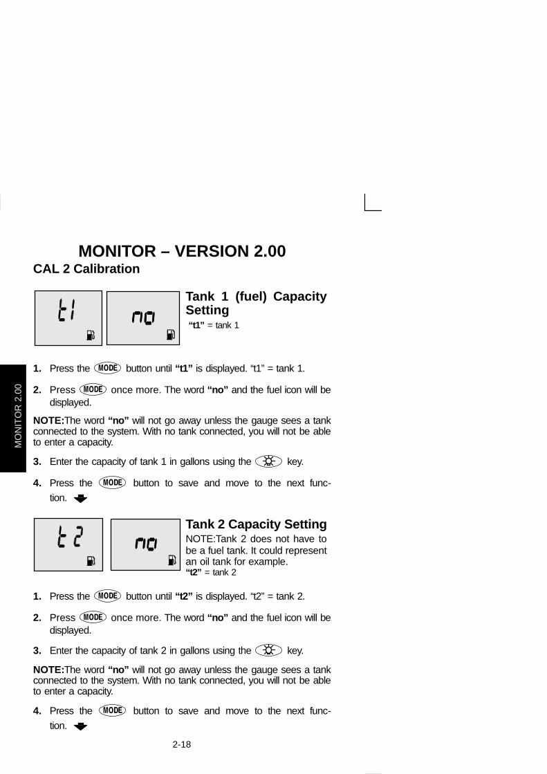
Tank 1 (fuel) CapacitySetting “t1” = tank 1
1. Press the button until “t1” is displayed. “t1” = tank 1.
2. Press once more. The word “no” and the fuel icon will bedisplayed.
NOTE:The word “no” will not go away unless the gauge sees a tankconnected to the system. With no tank connected, you will not be ableto enter a capacity.
3. Enter the capacity of tank 1 in gallons using the key.
4. Press the button to save and move to the next func-
tion.
Tank 2 Capacity SettingNOTE:Tank 2 does not have tobe a fuel tank. It could representan oil tank for example.“t2” = tank 2
1. Press the button until “t2” is displayed. “t2” = tank 2.
2. Press once more. The word “no” and the fuel icon will bedisplayed.
3. Enter the capacity of tank 2 in gallons using the key.
NOTE:The word “no” will not go away unless the gauge sees a tankconnected to the system. With no tank connected, you will not be ableto enter a capacity.
4. Press the button to save and move to the next func-
tion.

MO
NIT
OR
2.0
0
2-19
MONITOR – VERSION 2.00CAL 2 Calibration
Tank 1 CalibrationOnce the capacities have beenentered, you need to. Selectwhether you want to calibratefuel tank 1 ” ’t1”.NOTE: The gauge will not let youcalibrate the fuel tank until the ca-pacity had been entered).
1. Press the button to select 1= on, 0 = off. Selecting “1” willcontinue fuel tank calibration.
��
Tank 1 Calibration 0%SettingHave the fuel tank level atempty.
2. Press the button to save. Press the button to ad-
vance to 25% setting.
25 Percent Fuel to Add
��
Tank 1 Calibration 25%SettingAdding the amount of fuel shownwill raise fuel tank level to 25 per-cent.NOTE:The quantity of “Fuel toAdd” is determined by the fueltank capacity number entered
3. Add the displayed amount of fuel to the fuel tank.
4. Press the button to save. Press the button to ad-
vance to 50% setting.

MO
NIT
OR
2.0
0
2-20
MONITOR – VERSION 2.00CAL 2 Calibration
50 Percent Fuel to Add
��
Tank 1 Calibration 50%SettingAdding the amount of fuel shownwill raise fuel tank level to 50 per-cent.NOTE:The quantity of “Fuel toAdd” is determined by the fueltank capacity number entered
5. Add the displayed amount of fuel to the fuel tank.
6. Press the button to save. Press the button to ad-
vance to 75% setting.
75 Percent Fuel to Add
��
Tank 1 Calibration 75%SettingAdding the amount of fuel shownwill raise fuel tank level to 75 per-cent.NOTE:The quantity of “Fuel toAdd” is determined by the fueltank capacity number entered
7. Add the displayed amount of fuel to the fuel tank.
8. Press the button to save. Press the button to ad-
vance to full% setting.
Full Percent Fuel to Add
��
Tank 1 Calibration FullSettingAdd the amount of fuel to fill thefuel tank.
9. Add the amount of fuel to fill the fuel tank.
10. Press the button to save. Press the button to ad-
vance to next function.

MO
NIT
OR
2.0
0
2-21
MONITOR – VERSION 2.00CAL 2 Calibration
Tank 2 CalibrationSelect whether you want to cali-brate tank 2. NOTE: Tank 2 does not have tobe a fuel tank. It could representan oil tank for example. NOTE: The gauge will not let youcalibrate the tank until the capac-ity had been entered).
1. Press the button until “t2” is displayed. “t2” = tank 2.
2. Press the button to select 1= on, 0 = off. Selecting “1” willcontinue tank 2 calibration.
3. Press the button to continue.
Tank 2 Calibration IconSelectionSelect one of three icons fortank 2 display screen. (oil, wa-ter/waste, fuel).
1. Press the button, you will see a blinking icon. Using the
button, select which icon you want tank 2 to be, (oil, fuel,or water/waste).
NOTE:If you choose oil or water/waste icon, no further tank 2 cal-ibration will be needed. If tank 2 will be for fuel, continue tank 2 pro-cedure.
2. Press the button to continue.
��
Tank 2 Calibration 0%SettingHave the fuel tank level atempty.
3. Press the button to save. Press the button to ad-
vance to 25% setting.

MO
NIT
OR
2.0
0
2-22
MONITOR – VERSION 2.00CAL 2 Calibration
25 Percent Fuel to Add
��
Tank 2 Calibration 25%SettingAdding the amount of fuel shownwill raise fuel tank level to 25 per-cent.NOTE :The quantity of fuel to addis determined by the fuel tank ca-pacity number entered.
4. Add the displayed amount of fuel to the fuel tank.
5. Press the button to save. Press the button to ad-
vance to 50% setting.
50 Percent Fuel to Add
��
Tank 2 Calibration 50%SettingAdding the amount of fuel shownwill raise fuel tank level to 50 per-cent.NOTE:The quantity of fuel to addis determined by the fuel tank ca-pacity number entered.
6. Add the displayed amount of fuel to the fuel tank.
7. Press the button to save. Press the button to ad-
vance to 75% setting.
75 Percent Fuel to Add
��
Tank 2 Calibration 75%SettingAdding the amount of fuel shownwill raise fuel tank level to 75 per-cent.NOTE:The quantity of fuel to addis determined by the fuel tank ca-pacity number entered.
8. Add the displayed amount of fuel to the fuel tank.
9. Press the button to save. Press the button to ad-
vance to full% setting.

MO
NIT
OR
2.0
0
2-23
MONITOR – VERSION 2.00CAL 2 Calibration
Full Percent Fuel to Add
��
Tank 2 Calibration FullSettingAdd the amount of fuel to fill thefuel tank.
10. Add the amount of fuel to fill the fuel tank.
11. Press the button to save. Press the button to ad-
vance to next function.

SY
ST
EM
TA
CH
& S
PE
ED
Part 3System Tach and Speedometer
Basic Operation and Features 3-1. . . . . . . . . . . . . . . . Auto Detection Engine Function 3-3. . . . . . . . . . . . . . Master Reset 3-3. . . . . . . . . . . . . . . . . . . . . . . . . . . . . . Speedometer Display Screens 3-4. . . . . . . . . . . . . . . Tachometer Display Screens 3-6. . . . . . . . . . . . . . . . . Troll Control 3-8. . . . . . . . . . . . . . . . . . . . . . . . . . . . . . . Warning System 3-10. . . . . . . . . . . . . . . . . . . . . . . . . . . Warning Display Screens 3-11. . . . . . . . . . . . . . . . . . . Cal 1 Tachometer Calibration 3-15. . . . . . . . . . . . . . . . Cal 2 Tachometer Calibration 3-18. . . . . . . . . . . . . . . . Cal 1 Speedometer Calibration 3-22. . . . . . . . . . . . . . Cal 2 Speedometer Calibration 3-24. . . . . . . . . . . . . .
NOTE:This manual shows all the Monitor displayscreens that are available. Depending on your typeof engine, not all these screens will apply.
System Tach and Speedometer are compatiblewith:2002 model year Mercury Outboard models that aredesigned for use with SmartCraft.MerCruiser model 8.1/496

SYSTEM TACH & SPEED
3-0

SY
ST
EM
TA
CH
& S
PE
ED
3-1
SYSTEM TACH & SPEEDOMETERTachometer Speedometer
0
1
23 4
5
6
7 0
10
2030
4050
60
70
80
Basic Operation and FeaturesPower up: Each gauge will power up when the ignition is turned on.Gauges will stay on as long as the ignition is on.
Lights: The brightness and contrast are adjustable.
Buttons: The MODE button is used for selecting information screens.The “+” and “–” buttons are used for setting engine speed during trollcontrol and setting gauge calibrations.
Troll Control: Allows the operator to set and control the idle speedof the engine for trolling without using the throttle.
Engine Guardian System: Monitors the critical sensors on the enginefor any early indications of problems. The system will respond to aproblem by reducing engine speed in order to maintain a safe operat-ing condition.
Warning System: The system will sound the warning horn and displaythe warning message.
SY
ST
EM
TA
CH
& S
PE
ED
3-2
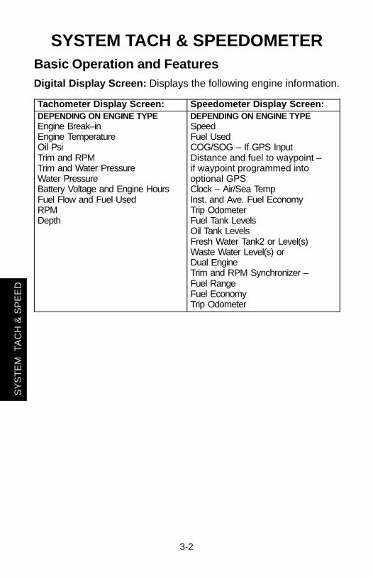
SYSTEM TACH & SPEEDOMETERBasic Operation and FeaturesDigital Display Screen: Displays the following engine information.
Tachometer Display Screen: Speedometer Display Screen:DEPENDING ON ENGINE TYPEEngine Break–inEngine TemperatureOil PsiTrim and RPMTrim and Water PressureWater PressureBattery Voltage and Engine HoursFuel Flow and Fuel UsedRPMDepth
DEPENDING ON ENGINE TYPESpeedFuel UsedCOG/SOG – If GPS InputDistance and fuel to waypoint – if waypoint programmed intooptional GPSClock – Air/Sea TempInst. and Ave. Fuel EconomyTrip OdometerFuel Tank LevelsOil Tank LevelsFresh Water Tank2 or Level(s)Waste Water Level(s) or Dual EngineTrim and RPM Synchronizer –Fuel RangeFuel EconomyTrip Odometer

SY
ST
EM
TA
CH
& S
PE
ED
3-3
SYSTEM TACH & SPEEDOMETERAuto-Detection Engine FunctionOn first time power up of gauge or after a “Master Reset”, gauge willshow “Auto detect”. Upon pressing the mode button, gauge will auto-matically determine engine type. This will preset the data monitoringscreens accordingly. The intention is to make initial setup easier. Ifgauge shows a warning of “No Starboard Engine” or “Multiple Star-board Engines”, engine will need to be properly selected (Port andStbd) using a Mercury engine diagnostic tool. “Master Reset” and“Auto detect” again. (Refer to “Master Reset”).
System tach and speed come standard with the “Engine Auto–detection Screen” this screen lets the gauge on its initial power upautomatically detect which engine type you are using and preconfi-gure the gauge to match that vessel type.
Master ResetYou can return the gauge back to factory presets through the MasterReset command.
IMPORTANT: Performing a master reset will reset the unit backto all factory defaults, thus eliminating any installation calibra-tions performed during set up of product.
By pressing TROLL– and TROLL
+ simultaneously for approximately 10seconds (Until the graphic bars “collide”). You will be able to restorethe unit back to factory presets.

SY
ST
EM
TA
CH
& S
PE
ED
3-4
SYSTEM TACH & SPEEDOMETER
4
3
2
1
5Continued Next Page
Speedometer
0
10
20
3040
50
60
70
80
Speedometer Display ScreensNOT ALL SCREENS MAY APPLY TO YOUR ENGINE TYPE.
When the ignition is turned on, the speedometer will show the lastscreen that was displayed before the ignition was turned off.
Press MODE to change display screens. You can revert back to the
previous screen by pressing and holding MODE for 2 seconds. Thiswill reverse the display rotation.
NOTE:Readings can be displayed in English (U.S.) or Metric. Referto Calibrations.
NOTE:Descriptions are not necessarily in order on the gauge. Orderchanges depending on engine type.
1. Clock - Temp – Clock, air temperature and water temperature.The air and water temperature sensors will have to be connectedto obtain display readings.
2. Fuel Level – Displays the amount of fuel remaining.
3. Oil Level – Displays the amount of engine oil remaining, or wa-ter/waste tank level (if attached).
4. RPM Synchronizer – Dual Engines Only – Monitors the revolu-tions of both engines.
5. Trim Synchronizer – Dual Engines Only – Displays the trim posi-tion of both engines. Simplifies keeping trim levels equal.

SY
ST
EM
TA
CH
& S
PE
ED
3-5
SYSTEM TACH & SPEEDOMETER
7
8
9
6
Speedometer
0
10
20
3040
50
60
70
80
Speedometer Display Screens6. Range – The estimated range is based on boat speed, fuel con-
sumption and fuel remaining in the tank. The numbers displayedindicates an estimate of the distance you can travel with the re-maining fuel. Speed input required (Paddle Wheel, Pitot Pressureor GPS).
7. Fuel Economy – The display shows average “AVG” fuel con-sumption as well as Instantaneous “INST” fuel economy. Thenumbers displayed indicate miles per gallon “MPG” or kilometerper liter “KM/L”. Fuel Reset – To reset, select the display screen and pressMODE and TROLL
– buttons.
8. Trip Odometer – Tells how far you’ve gone since you last reset thegauge to zero. Trip Reset – To reset, select the display screen andpress MODE and TROLL
– buttons.
9. Digital Speedometer – Can display boat speed in miles perhour, kilometer per hour, or nautical miles per hour. Thespeedometer will use the paddle wheel for its low speed read-ings but will switch to the speedo or GPS (if connected) for highspeed readings. (Transition point setting is described in Cal2).

SY
ST
EM
TA
CH
& S
PE
ED
3-6
SYSTEM TACH & SPEEDOMETER
4
3
2
1
5
° F
Continued Next Page
Tachometer
0
1
2
3 45
6
7
ENG
PSI
WATERPSI
Tachometer Display ScreensNOT ALL SCREENS MAY APPLY TO YOUR ENGINE TYPE.
When the ignition is turned on, the tachometer will display the lastscreen that was displayed before the ignition was turned off.
Press MODE to change display screens. You can revert back to the
previous screen by pressing and holding MODE for 2 seconds. Thiswill reverse the display rotation.
NOTE:Readings can be displayed in English (U.S.) or Metric. Referto Calibration.
1. Engine Break-in – Displays time remaining on the break-in periodof a new engine. This screen will automatically disappear after thebreak-in period is complete.
2. Temperature – Displays engine coolant temperature.
3. Power Trim Angle – Displays trim angle of the outboard orsterndrive up to the maximum trim angle, and then displays thetrailer angle. 0 = down, 10 = maximum trim, and 25 = full trailer.
4. Power Trim Angle - Water Pressure – Displays trim angle of theengine and cooling system water pressure.
5. Water Pressure - Displays cooling system water pressure at theengine.

SY
ST
EM
TA
CH
& S
PE
ED
3-7
SYSTEM TACH & SPEEDOMETER
8
7
9
Tachometer
0
1
2
3 4
5
6
7
HRSVOLT
22.313.6
3200
FUEL USED
2.4 22.0
6 OILPSI
DEPTHFEET
Tachometer Display Screens6. Oil Pressure – Displays engine oil pressure in units of Psi or Bar.
7. Battery Voltage – Displays voltage level (condition) of battery.Also records the running time of engine.
8. Fuel Flow – Displays engine fuel use in gallons per hour or litersper hours.
9. Digital Tachometer – Displays engine speed in RevolutionsPer Minute (RPM).
10. Water Depth – Displays the depth of water under the transducerif connected. The water depth screen can be turned on or off inCAL 1 Calibration. You can set an alarm to trigger whenever theboat moves into water shallower than the alarm level. Refer toCAL 2 Calibration for water depth alarm and offset settings.
NOTE:You must have a depth transducer (purchased separately)connected to the system in order for this screen to operate.

SY
ST
EM
TA
CH
& S
PE
ED
3-8
SYSTEM TACH & SPEEDOMETER
TROLL+
TROLL–TROLL
+TROLL
–
SpeedometerTachometer
Actual Speed Set SpeedActual Speed Set Speed
TRa
0
1
23 4
5
6
70 80
Troll ControlBasic Operation
NOTE:Troll control may not be available on all engine models.
With troll control you can maintain a trolling speed of 550 to1000 rpmwithout using the throttle.
NOTE:Troll control min/max range may change depending on en-gine type.
You can set the troll control by using either the tachometer orspeedometer. Tachometer will set the speed in RPM and speedom-eter will set the speed in MPH, Kph or KN.
You can shut off troll control anytime by pushing the MODE buttonwhen in the troll display screen or by moving the throttle.
If you have troll control set at a desired speed and then you shut offthe troll control, the system remembers the set speed and will returnto that speed when re-engaged.
The display screen will revert back to the previous screen after 10 sec-onds of no activity. Push the TROLL
+ or TROLL– button to reactivate the
display screen.
When the troll control is engaged and you are out of the troll controlscreen, a flashing signal “TR” (a) will appear in the upper left cornerof the display to indicate troll control is still running.

SY
ST
EM
TA
CH
& S
PE
ED
3-9
SYSTEM TACH & SPEEDOMETER
0
TROLL+TROLL
–TROLL+
TROLL–
SpeedometerTachometer
Actual Speed Set SpeedActual Speed Set Speed
a b
1
23 4
5
6
7 0 80
Troll ControlTo Set Troll Control
1. With the engine running, shift engine into gear. Set engine speedat idle.
2. Push in the TROLL+ or TROLL
– button to bring up the troll control dis-play screen.
3. Press MODE to engage (turn on) the troll control.
4. Use the TROLL+ TROLL
– buttons to set the desired speed. Use (+)to increase speed and (–) to decrease speed.
5. If you set troll control to a higher speed than the troll rpm can bringthe boat to, the TARGET SPEED TOO FAST (a) message will ap-pear. Reduce troll speed.
6. If you set troll control to a slower speed than the troll rpm can bringthe boat to, the TARGET SPEED TOO SLOW (b) message will ap-pear. Increase troll speed.
To Get Out of Troll Control
There are three ways to turn off the troll control:
• Press the MODE button when in the troll display screen.
• Move the throttle to a different speed.
• Shift engine into neutral.
SY
ST
EM
TA
CH
& S
PE
ED
3-10
SYSTEM TACH & SPEEDOMETER
a cb
0
1
23 4
5
6
7 0 80
2
Warning SystemAlarms Warnings – When a problem is detected, the name of theoffending alarm appears on the display (a).
If problem can cause immediate engine damage, the Engine GuardianSystem (b) will respond to the problem by limiting engine power. Imme-diately reduce throttle speed to idle and refer to the warning messageson the following pages. Refer to the Engine Operation, MaintenanceManual for further explanation of the problem and the correct actionto take.
The alarm message will stay displayed until the mode button ispressed. If there are multiple alarms, these will cycle on the display atfive-second intervals.
If the mode button is pressed to a different screen, the flashing alarmsignal “AL” (c) will appear in the upper right corner to indicate therestill is a problem.

SY
ST
EM
TA
CH
& S
PE
ED
3-11
SYSTEM TACH & SPEEDOMETERWarning Display ScreensWhen a problem is detected with the engine, the warning displayscreens will alert the operator to the potential problem. Refer to theEngine Operation, Maintenance Manual for explanation of the prob-lem and the correct action to take.
WARNING DISPLAY SCREENS
PROBLEMTACHOMETER
DISPLAYSPEEDOMETER
DISPLAY
BATTERY �
ENGINE DATA BUS �
FAULT – HORN �
FAULT – IGNITION �
FAULT – INJECTOR �
FAULT – OIL PUMP �
FAULT – SENSOR �
FAULT – WATER TEMP �
LOW FUEL �
LOW OIL �
OIL TEMP �
OIL PSI �
OVERHEAT �
OVER SPEED �
PRESSURE �
RESERVE OIL �
WATER IN FUEL �
MAP �
MAT �
TPS �

SY
ST
EM
TA
CH
& S
PE
ED
3-12
SYSTEM TACH & SPEEDOMETER
1
3
4
5
2
7
8
60
1
23 4
5
6
7
Warning Display ScreensIMPORTANT: Refer to the Engine Operation, MaintenanceManual for further explanation of the problem and the correctaction to take.
1. OVERHEAT – The engine has overheated.
2. PRESSURE – There is insufficient water pressure in the coolingsystem.
3. OVERSPEED – Engine speed exceeded the maximum allowableRPM.
4. WATER IN FUEL – Water in the water-separating fuel filterreached the full level.
5. FAULT-HORN – Warning horn is not functioning correctly.
6. RESERVE OIL LOW – 2 STROKE OUTBOARD ONLY – Oil levelis critically low in the engine mounted oil reservoir tank.
7. FAULT-OIL PUMP – Oil pump has stopped functioning electrically.No lubricating oil is being supplied to the engine.
8. FAULT-INJECTOR – One or more of the fuel injectors have stopfunctioning electrically.

SY
ST
EM
TA
CH
& S
PE
ED
3-13
SYSTEM TACH & SPEEDOMETER
12
10
9
11
13
14
16
no starboardengine
150
1
23 4
5
6
7
MultipleStarboard Engine
Warning Display Screens9. FAULT-IGNITION – A problem has developed in the ignition sys-
tem.
10. BATTERY – The electrical system is not charging or the batterycharge is low.
11. ENGINE DATA BUS – The data communication link between thetachometer and engine is not connected.
12. FAULT-SENSOR – One of the sensors is not functioning correctly.13. FAULT-WATER TEMP – The sensor for measuring outside lake/
sea water temperature is not functioning correctly.14. NO STARBOARD ENGINE – Informs you that the Instrument
does not see the starboard engine computer. Usually indicatesthat no data is being transferred from the engine’s computer to thegauge. (Check wiring, also make sure both terminator resistors areinstalled in the bus). Make sure both ECM’s are not configured forport location using a DDT or Quicksilver Diagnostic Tool.
15. MULTIPLE STARBOARD ENGINE – SmartCraft Gauges arerecognizing multiple engines as starboard.
In multiple engine applications, each engine must first be assigned aposition (starboard, port, starboard2 or port2) with a Quicksilver Diag-nostic Tool before the system will function properly.If you have a dual engine application, you must first program the portengine with a Quicksilver Diagnostic Tool.16. OIL TEMPERATURE – Engine oil is overheating.

SY
ST
EM
TA
CH
& S
PE
ED
3-14
SYSTEM TACH & SPEEDOMETER
19
0
1
23 4
5
6
7
17
E F18
E F 22
20
21
Warning Display Screens17. OIL PRESSURE – There is insufficient oil pressure.
18. LOW FUEL LEVEL – This message serves as a warning that thefuel level in the fuel tank is critically low. You should stop for fuelimmediately to avoid running out.
19. LOW OIL LEVEL – OUTBOARD 2 STROKE ONLY – oil level inthe remote oil tank is low. You should stop and refill the oil tank im-mediately to avoid running out.
20. FAULT-MAP – Engine problem occurred. Have the enginechecked by your dealer.
21. FAULT-MAT – Engine problem occurred. Have the enginechecked by your dealer.
22. FAULT-TPS – Engine problem occurred. Have the enginechecked by your dealer.

SY
ST
EM
TA
CH
& S
PE
ED
3-15
SYSTEM TACH & SPEEDOMETERQuick Cal CalibrationQuick Cal – This calibration is for setting lighting and contrast.
1. Press in the MODE and TROLL+ buttons for up to 2 seconds to get
to Quick Cal screen.
2. Press MODE to advance through the calibration selections.
CAL 1 Tachometer CalibrationCal 1 – This calibration level lets you turn on and off the systemscreens. You may configure the system to display as little or as muchinformation as you prefer.
1. Press in the MODE and TROLL+ buttons and hold for approxi-
mately 7 seconds until you see the Cal 1 screen.
2. Press MODE to advance through the calibration selections.
[NO]
REMOTE SCREENS?
[YES][SAVE]
If yes is selected, then screen changesmade on this SC1000 tach will effectany other SC1000 tach in the system.NOTE: all tach will need to have this screenturned to “Yes” for this function to work.
[NO]
REMOTE LCD LIGHT?
[YES][SAVE]
If yes is selected, then lighting levelsmade on this SC1000 tach will effectany other SC1000 tach in the system.NOTE: all tach will need to have this screenturned to “Yes” for this function to work.
REMOTE LCD CONTRAST?
[YES][NO] [SAVE]
If yes is selected, then contrast levelsmade on this SC1000 tach will effectany other SC1000 tach in the system.NOTE: all tach will need to have this screenturned to “Yes” for this function to work.
[NO]
TRIM POPUP?
[YES][SAVE]
Do you want power trim display screento pop up momentarily when you trimthe engine?
(continued on next page)

SY
ST
EM
TA
CH
& S
PE
ED
3-16
SYSTEM TACH & SPEEDOMETERCAL 1 Tachometer Calibration
TRIM CALIBRATION
[EDIT][SKIP]
Choosing edit allows you to calibratethe gauge to the standard 0–10 unit trimand 11–25 trailer position scale.
TRIM FULL DOWN THENPRESS PLUS BUTTON
[SAVE][SKIP][DFLT]
TRIM FULL UP THENPRESS PLUS BUTTON
[SAVE][SKIP][DFLT]
TRIM TO TRAILER POINTTHEN PRESS PLUS BUTTON
[SAVE][SKIP][DFLT]
DISPLAY UNITS
[DOWN] [UP][SAVE]
Lets you change units of measurebetween English (standard) or Metric.
SPEED UNITS
[DOWN] [UP][SAVE]
Lets you select speed units. You canchoose from MPH (Miles Per Hour), KN(Nautical Miles Per Hour) or KMH(Kilometers Per Hour).
[NO] [YES][SAVE]
DEPTH SCREEN? Do you want to turn on the depth screen?(Remember: You must have a SmartCraft depth transducer connected to thesystem for this screen to operate)
ENGINE TEMP SCREEN?
[NO] [YES][SAVE]
Do you want to turn on the engine tempscreen?
(continued on next page)

SY
ST
EM
TA
CH
& S
PE
ED
3-17
SYSTEM TACH & SPEEDOMETERCAL 1 Tachometer Calibration
OIL TEMP SCREEN?
[NO] [YES][SAVE]
Do you want to turn on the oil tempscreen?
OIL PRESS SCREEN?
[NO] [YES][SAVE]
Do you want to turn on the oil pressurescreen?
TRIM AND PSI SCREEN?
[NO] [YES][SAVE]
Do you want to turn on the trim andwater pressure split screen?
WATER PSI SCREEN?
[NO] [YES][SAVE]
Do you want to turn on the water pressurescreen?
TRIM AND RPM SCREEN?
[NO] [YES][SAVE]
Do you want to turn on the trim and RPMsplit screen?
RPM SCREEN?
[NO] [YES][SAVE]
Do you want to turn on the digital RPMscreen?
SIMULATOR MODE?
[NO] [YES][SAVE]
Do you want to turn on a simulationmode? (used for demonstrationpurposes).
EXIT?
[NO] [CAL2][SAVE]
Do you want to exit calibration? Or jumpstraight into calibration level 2?

SY
ST
EM
TA
CH
& S
PE
ED
3-18
SYSTEM TACH & SPEEDOMETERCAL 2 Tachometer CalibrationCAL 2 – This calibration level lets you configure the system sensorinputs.
1. Press in the MODE and TROLL+ buttons and hold for approximately
10 seconds for calibration2 (Cal2) screen.
2. Press MODE to advance through the calibration selections.
EXTERNAL SENSORS
[EDIT][SKIP]
This section lets you enable or disablethe following external sensor inputs.
PITOT SENSOR?
[NO] [YES][SAVE]
Is the boat equipped with a pitot sensorto measure boat speed?
PADDLE SENSOR?
[NO] [YES][SAVE]
Is the boat equipped with a paddlewheel to measure boat speed?
TRIM SENSOR?
[NO] [YES][SAVE]
Is the boat equipped with a trim sensor?
SEA TEMP?
[NO] [YES][SAVE]
Is the boat equipped with a watertemperature sensor?
INVERT STEERING
[NO] [SAVE] [YES]
Is steering angle showing up on the linkgauge opposite the direction that it shouldbe? If it is then this feature will reverse thesignal so it is displayed properly.
(continued on next page)

SY
ST
EM
TA
CH
& S
PE
ED
3-19
SYSTEM TACH & SPEEDOMETERCAL 2 Tachometer Calibration
SPEED OPTION
[EDIT][SKIP]
This section lets you configure thefollowing speed sensors.
PITOT SENSOR?
[NO] [YES][SAVE]
Select pitot transducer type. You canchoose 100 or 200 PSI. (100 PSI is themost common)
PITOT SENSOR MULTIPLIER
[DOWN] [UP][SAVE]
Adjust the pitot pressure sensor forcorrecting display readings that are tohigh/low.
PADDLE SENSOR PULSE FAC-TOR
[DOWN] [UP][SAVE]
Adjust paddle wheel frequency for displayreadings that are to high/low.
PADDLE TO PITOT TRANSITION
[DOWN] [UP][SAVE]
Set the speed at which the gauge stopslooking at the paddle wheel and startsusing pitot to measure boat speed.
(continued on next page)
There are three methods for calibrating fuel tank levelmonitoring feature:
First: Do nothing. Linear readout based on raw sensor values. Thismode does not factor in irregular tank shapes.
Second: By following the tank calibration procedure described onnext page, but without actually adding fuel. System Tach will supplyan estimated range value based on linear interpolation of the sensorrange values. This mode does not factor in irregular tank shapes.
Third: By following the tank calibration procedure described on nextpage completely, which means adding fuel at each calibration point.System Tach will display an estimated range value that factors in thetank shape.

SY
ST
EM
TA
CH
& S
PE
ED
3-20
SYSTEM TACH & SPEEDOMETERCAL 2 Tachometer Calibration
FUEL TANK CAPACITY
[DOWN] [UP][SAVE]
Lets you enter the capacity of yourboats fuel tank. This option is the samefor tank 1 as it is for tank 2.
CALIBRATION FUEL TANK
[EDIT][SKIP]
Lets you enter the mode where you cancalibrate your fuel tank. Fuel tankcalibration procedure is the same fortank 1 as it is for tank 2.
EMPTY TANK THENPRESS PLUS BUTTON
[DFLT] [SAVE][SKIP]
You can choose to have an empty tankand hit SAVE, or hit DFLT and a defaultvalue will be entered based on thecapacity of the tank.
FILL TO 1/4 THENPRESS PLUS BUTTON
[DFLT] [SAVE][SKIP]
You can choose to have tank at 1/4and hit SAVE, or hit DFLT and a defaultvalue will be entered based on the ca-pacity of the tank.
FILL TO 1/2 THENPRESS PLUS BUTTON
[DFLT] [SAVE][SKIP]
You can choose to have tank at 1/2and hit SAVE, or hit DFLT and a defaultvalue will be entered based on the ca-pacity of the tank.
FILL TO 3/4 THENPRESS PLUS BUTTON
[DFLT] [SAVE][SKIP]
You can choose to have tank at 3/4and hit SAVE, or hit DFLT and a defaultvalue will be entered based on the ca-pacity of the tank.
[DFLT] [SAVE][SKIP]
FILL TO FULL THENPRESS PLUS BUTTON
You can choose to have tank at fulland hit SAVE, or hit DFLT and a defaultvalue will be entered based on the ca-pacity of the tank.
(continued on next page)

SY
ST
EM
TA
CH
& S
PE
ED
3-21
SYSTEM TACH & SPEEDOMETERCAL 2 Tachometer Calibration
DEPTH SENSOR OFFSET
[DOWN] [UP][SAVE]
Lets you electronically configure a depthoffset. Entering a negative number givesyou a water line offset. A positive numbergives you a keel offset.
DEPTH ALARM
[DOWN] [UP][SAVE]
Lets you enter a depth value. When thedepth transducer reads that value orbelow, the shallow water alarm will sound.

SY
ST
EM
TA
CH
& S
PE
ED
3-22
SYSTEM TACH & SPEEDOMETERQuick Cal CalibrationQuick Cal – This calibration is for setting lighting and contrast.
1. Press in the MODE and TROLL+ buttons for up to 2 seconds to get
to Quick Cal screen.
2. Press MODE to advance through the calibration selections.
CAL 1 Speedometer CalibrationCal 1 – This calibration level lets you turn on and off the systemscreens. You may configure the system to display as little or as muchinformation as you prefer.
1. Press in the MODE and TROLL+ buttons and hold for approxi-
mately 7 seconds until you see the Cal 1 screen.
2. Press MODE to advance through the calibration selections.
REMOTE LCD LIGHT?
[NO] [YES][SAVE]
Enables you to set the lighting levelson all the SC1000 simultaneously fromthis gauge.
REMOTE LCD CONTRAST?
[NO] [YES][SAVE]
Enables you to control the contrastfrom another System TACH/Speedsimultaneously from this gauge.
TIME
[NO] [EDIT][SKIP]
Allows you to set the time.
TIME FORMAT
[DOWN] [UP][SAVE]
Choose between a 12 hour and 24 hourformat.
USE GPS TIME?
[DOWN] [UP][SAVE]
If you have a GPS connected thisfeature enables the gauge to let theGPS update the gauges internal clock.
(continued on next page)

SY
ST
EM
TA
CH
& S
PE
ED
3-23
SYSTEM TACH & SPEEDOMETERCAL 1 Speedometer Calibration
CALIBRATIONHOUR 12:00 AM
[DOWN] [UP][SAVE]
Adjust the gauges internal clock tomatch your local time. First set the hoursthen press MODE button to set theminutes.
DISPLAY UNITS
[DOWN] [UP][SAVE]
Lets you change units of measurementbetween English (standard) or Metric.
SPEED UNITS
[DOWN] [UP][SAVE]
Lets you select the units at which speedis displayed. You can choose from MPH(Miles Per Hour), KTS (Knots), or KMH(Kilometers Per Hour).
TO WAYPOINT SCREEN?
[NO] [YES][SAVE]
If you have a GPS connected you canturn on the screen that shows yourdistance and fuel to a waypoint.
SIMULATOR MODE?
[NO] [YES][SAVE]
Do you want to turn on a simulationmode? (Used for demonstrationpurposes).
EXIT?
[NO] [CAL2][YES]
Do you want to exit calibration? Or jumpstraight into calibration level 2?

SY
ST
EM
TA
CH
& S
PE
ED
3-24
SYSTEM TACH & SPEEDOMETERCAL 2 Speedometer CalibrationCAL 2 – This calibration level lets you configure the system sensorinputs.
1. Press in the MODE and TROLL+ buttons and hold for approximately
10 seconds for calibration2 (Cal2) screen.
2. Press MODE to advance through the calibration selections.
EXTERNAL SENSORS
[EDIT][SKIP]
This lets you enable or disable externalsensor inputs.
AIR TEMP?
[NO] [YES][SAVE]
Are you using a air temp. sensor?
GPS?
[NO] [YES][SAVE]
Do you have a GPS sensor installed?
USE GPS SPEED?
[NO] [YES][SAVE]
Use the GPS input to drive the speeddisplay?
WATER TEMPERATUREADJUST
[UP][SAVE][DOWN]
Adjust water temp. transducer to matchactual sea water temperature.

VDO
SM
AR
T T
AC
H &
SP
EE
D
Part 4Smart Tach and Speedometer
Basic Operation and Features 4-1. . . . . . . . . . . . . . . . Speedometer Display Screens 4-2. . . . . . . . . . . . . . . Tachometer Display Screens 4-4. . . . . . . . . . . . . . . . . Troll Control 4-6. . . . . . . . . . . . . . . . . . . . . . . . . . . . . . . Warning System 4-8. . . . . . . . . . . . . . . . . . . . . . . . . . . . Warning Display Screens 4-9. . . . . . . . . . . . . . . . . . . . Tachometer Calibration 4-12. . . . . . . . . . . . . . . . . . . . . Speedometer Calibration 4-17. . . . . . . . . . . . . . . . . . .
NOTE:This manual shows all the Monitor displayscreens that are available. Depending on your typeof engine, not all these screens will apply.
Smart Tach and Speedometer are compatiblewith:2001 model year and newer Mercury Outboard mod-els that are designed for use with SmartCraft.

SMART TACH & SPEED
4-0

SM
AR
T T
AC
H &
SP
EE
D
4-1
SMART TACH & SPEEDOMETERgog95
Tachometer Speedometer
osl1
Basic Operation and FeaturesPower up: Each gauge will power up when the ignition is turned on.Gauges will stay on as long as the ignition is on.
Lights: The brightness and contrast are adjustable.
Buttons: The MODE button is used for selecting informationscreens. The + and – buttons are used for setting engine speed dur-ing troll control and setting gauge calibrations.
Troll Control: Allows the operator to set and control the idle speedof the engine for trolling without using the throttle.
Engine Guardian System: Monitors the critical sensors on the en-gine for any early indications of problems. The system will respondto a problem by reducing engine speed in order to maintain a safeoperating condition.
Warning System: The system will sound the warning horn and dis-play the warning message.Tachometer Display Screen: Speedometer Display Screen:Digital TachometerHour MeterPower Trim AngleFuel FlowEngine TemperatureBattery VoltageWater Pressure
Clock and TemperatureFuel Tank Level(s)Oil Tank Level(s)Fuel EconomyFuel RangeTrip OdometerDigital SpeedometerBarometer Reading

SM
AR
T T
AC
H &
SP
EE
D
4-2
SMART TACH & SPEEDOMETERgog95
4
3
2
1
5Continued Next Page
Speedometer
osl2
Speedometer DisplaysWhen the ignition is turned on, the speedometer will show the lastscreen that was displayed before the ignition was turned off.
Press MODE to change display screens. You can revert back to the
previous screen by pressing and holding MODE for 2 seconds. Thiswill reverse the display rotation.
NOTE:Readings can be displayed in English (U.S.) or Metric. Referto Calibrations.
1. Clock - Temp – Clock, air temperature and water temperature.The air and water temperature sensors will have to be con-nected to obtain display readings.
2. Fuel Level – Displays the amount of fuel remaining.
3. Oil Level – Displays the amount of engine oil remaining.
4. RPM Synchronizer – Dual Engines – Monitors the revolutions ofboth engines. Allows throttle adjustments to keep each runninguniformly.
5. Trim Synchronizer – Dual Engines – Displays the trim position ofboth engines. Simplifies keeping trim levels equal.

SM
AR
T T
AC
H &
SP
EE
D
4-3
SMART TACH & SPEEDOMETERgog95
7
8
9
10
6Speedometer
osl3
Speedometer Displays6. Traveling Range – The estimated traveling range is based on
current fuel consumption and fuel remaining in the tank. Thenumbers displayed indicates an estimate of the distance youcan travel with the remaining fuel.
7. Fuel Economy – The display shows average “AVG” fuel con-sumption as well as Instantaneous “INST” fuel economy. Thenumbers displayed indicate miles per gallon “MPG” or kilometerper liter “KM/L”. Reset – To reset, select the display screen andpress MODE and TROLL
– buttons.
8. Trip Odometer – Tells how far you’ve gone since you last set thegauge to zero. Trip Reset – To reset, select the display screen andpress MODE and TROLL
– buttons.
9. Digital Speedometer – Can display boat speed in miles perhour, kilometer per hour, or knots. The digital speedometer willcontinue to increase even if needle is at maximum. Thespeedometer will use the paddle wheel for its low speed read-ings but will switch to the speedo or GPS (if connected) for highspeed readings.
10. Barometer – Shows the barometric pressure reading only at thetime the ignition was turned on.

SM
AR
T T
AC
H &
SP
EE
D
4-4
SMART TACH & SPEEDOMETERgog95
4
3
2
1
5
° F
Continued Next Page
Tachometer
osl4
Tachometer DisplaysWhen the ignition is turned on, the tachometer will display the lastscreen that was displayed before the ignition was turned off.
Press MODE to change display screens. You can revert back to the
previous screen by pressing and holding MODE for 2 seconds. Thiswill reverse the display rotation.
NOTE:Readings can be displayed in English (U.S.) or Metric. Referto Calibration.
1. Engine Break-in – Displays time remaining on the break-in peri-od of a new engine. This screen will automatically disappear af-ter the break-in period is complete.
2. Power Trim Angle - Water Pressure – Displays trim angle ofthe outboard and cooling system water pressure.
3. Fuel Flow – Displays engine fuel use in gallons per hour or litersper hours.
4. Temperature – Displays engine coolant temperature from Coldto Hot.
5. Battery Voltage – Displays voltage level (condition) of battery.

SM
AR
T T
AC
H &
SP
EE
D
4-5
SMART TACH & SPEEDOMETERgog95
9
8
7
6
Tachometer
osl5
Tachometer Displays6. Water Pressure: Displays cooling system water pressure at the
engine.
7. Power Trim Angle: Displays trim angle of the outboard up to themaximum trim angle, and then displays the trailer angle. 0 =down, 10 = full trim, and 25 = full trailer.
8. Digital Tachometer: Displays engine speed in Revolutions PerMinute (RPM).
9. Hour Meter: Records the running time of the engine.

SM
AR
T T
AC
H &
SP
EE
D
4-6
SMART TACH & SPEEDOMETERgog95
TROLL+
TROLL–TROLL
+TROLL
–
SpeedometerTachometer
Actual Speed Set SpeedActual Speed Set Speed
TRa
oso6
Troll ControlBasic Operation
With troll control you can maintain a trolling speed of 550 to1000 rpmwithout using the throttle. See NOTE: following.
NOTE:Avoid using a very low rpm trolling speed for an extended peri-od of time. Doing so could result in a low-battery voltage condition.
You can set the troll control by using either the tachometer orspeedometer. Tachometer will set the speed in RPM and speedom-eter will set the speed in MPH.
You can shut off troll control anytime by pushing the MODE buttonwhen in the troll display screen or moving the throttle.
If you have troll control set at a desired speed and then you shut offthe troll control, the system remembers the set speed and will returnto that speed when re-engaged.
The display screen will revert back to the previous screen after 10seconds of no activity. Push the TROLL
+ or TROLL– button to reactivate
the display screen.
When the troll control is engaged and you are out of the troll controlscreen, a flashing signal “TR” (a) will appear in the upper left cornerof the display to indicate troll control is still running.
SM
AR
T T
AC
H &
SP
EE
D
4-7
SMART TACH & SPEEDOMETERgog95
TROLL+TROLL
–TROLL+
TROLL–
SpeedometerTachometer
Actual Speed Set SpeedActual Speed Set Speed
a b
osl7
Troll ControlTo Set Troll Control
1. With the engine running, shift outboard into gear. Set enginespeed at idle.
2. Push in the TROLL+ or TROLL
– button to bring up the troll controldisplay screen.
3. Press MODE to engage (turn on) the troll control.
4. Use the TROLL+ TROLL
– buttons to set the desired speed. Use (+)to increase speed and (–) to decrease speed.
5. If you set troll control to a higher speed than the troll rpm canbring the boat to, the TARGET SPEED TOO FAST (a) messagewill appear. Reduce troll speed.
6. If you set troll control to a slower speed than the troll rpm canbring the boat to, the TARGET SPEED TOO SLOW (b) messagewill appear. Increase troll speed.
To Get Out of Troll Control
There are three ways to turn off the troll control:
• Press the MODE button when in the troll display screen.• Move the throttle to a different speed.• Shift outboard into neutral.

SM
AR
T T
AC
H &
SP
EE
D
4-8
SMART TACH & SPEEDOMETER
a cb
0
1
23 4
5
6
7 0 80
2
Warning SystemAlarms Warnings – When a problem is detected, the name of theoffending alarm appears on the display (a).
If problem can cause immediate engine damage, the Engine GuardianSystem (b) will respond to the problem by limiting engine power. Imme-diately reduce throttle speed to idle and refer to the warning messageson the following pages. Refer to the Engine Operation, MaintenanceManual for further explanation of the problem and the correct actionto take.
The alarm message will stay displayed until the mode button ispressed. If there are multiple alarms, these will cycle on the display atfive-second intervals.
If the mode button is pressed to a different screen, the flashing alarmsignal “AL” (c) will appear in the upper right corner to indicate therestill is a problem.

SM
AR
T T
AC
H &
SP
EE
D
4-9
SMART TACH & SPEEDOMETERWarning Display ScreensWhen a problem is detected with the engine, the warning displayscreens will alert the operator to the potential problem. Refer to theEngine Operation, Maintenance Manual for explanation of the prob-lem and the correct action to take.
WARNING DISPLAY SCREENS
PROBLEMTACHOMETER
DISPLAYSPEEDOMETER
DISPLAY
BATTERY �
ENGINE DATA BUS �
FAULT – HORN �
FAULT – IGNITION �
FAULT – INJECTOR �
FAULT – OIL PUMP �
FAULT – SENSOR �
FAULT – WATER TEMP �
LOW FUEL �
LOW OIL �
OVERHEAT �
OVER SPEED �
PRESSURE �
RESERVE OIL �
UNIT MISMATCH(MULTI ENGINE) �
WATER IN FUEL �

SM
AR
T T
AC
H &
SP
EE
D
4-10
SMART TACH & SPEEDOMETER
1
3
4
5
2
7
8
60
1
23 4
5
6
7
Warning Display ScreensIMPORTANT: Refer to the Engine Operation, MaintenanceManual for further explanation of the problem and the correctaction to take.
1. OVERHEAT – The engine has overheated.
2. PRESSURE – There is insufficient water pressure in the coolingsystem.
3. OVERSPEED – Engine speed exceeded the maximum allowableRPM.
4. WATER IN FUEL – Water in the water-separating fuel filterreached the full level.
5. FAULT-HORN – Warning horn is not functioning correctly.
6. RESERVE OIL LOW – 2 STROKE OUTBOARD ONlY – Oil levelis critically low in the engine mounted oil reservoir tank.
7. FAULT-OIL PUMP – Oil pump has stopped functioning electrically.No lubricating oil is being supplied to the engine.
8. FAULT-INJECTOR – One or more of the fuel injectors have stopfunctioning electrically.

SM
AR
T T
AC
H &
SP
EE
D
4-11
SMART TACH & SPEEDOMETER
12
10
9
11
13
14
16
150
1
23 4
5
6
7
Warning Display ScreensIMPORTANT: Refer to the Engine Operation, MaintenanceManual for further explanation of the problem and the correctaction to take.
9. FAULT-IGNITION – A problem has developed in the ignition sys-tem.
10. BATTERY – The electrical system is not charging or the batterycharge is low.
11. ENGINE DATA BUS – The data communication link between thetachometer and engine is not connected.
12. FAULT-SENSOR – One of the sensors is not functioning correctly.13. FAULT-WATER TEMP – The sensor for measuring outside lake/
sea water temperature is not functioning correctly.
14. UNIT MISMATCH – (Multi Engines) This message tells you thatthe tachometers are not calibrated alike. For example, this couldhappen if one tachometer reading is English and the other is inMetric. Re-calibrate the tachometers.
15. LOW FUEL LEVEL – This message serves as a warning that thefuel level in the fuel tank is critically low. You should stop for fuelimmediately to avoid running out.
16. LOW OIL LEVEL – OUTBOARD 2 STROKE ONLY – oil level inthe remote oil tank is low. You should stop and refill the oil tank im-mediately to avoid running out.an

SM
AR
T T
AC
H &
SP
EE
D
4-12
SMART TACH & SPEEDOMETERosl26
Tachometer CalibrationNOTE:When calibrating multi tachometers (multi engines) turn igni-tion on for all the tachometers.Simple Calibration – This calibration for setting lighting and a fewother common screens can be made while engine is running.
1. Press in the MODE and TROLL+ buttons for calibration screen.
2. Press MODE to advance through the calibration selections.
Advanced Calibration – This calibration goes through all modeselections.
1. Turn ignition key to the off position.
2. Hold TROLL+ TROLL
– and turn ignition on.
3. Press and hold MODE for 2 seconds to bring up the calibrationscreen.
4. Press MODE to advance through the calibration selections.
[DOWN]
CALIBRATIONBRIGHTNESS
[UP][SAVE]
Press – or + to adjust level. PressMODE to save setting
CALIBRATIONBRIGHTNESS
[ YES ][ NO ]SET ALL INSTRUMENTS?
Do you want the same brightness lev-el for all SmartCraft gauges? Press +for yes. Press MODE for no.
[DOWN]
CALIBRATION
[UP][SAVE]
CONTRAST
Press – or + to adjust level. PressMODE to save setting
CONTRASTCALIBRATION
[ YES ][ NO ]SET ALL INSTRUMENTS?
Do you want the same contrast levelfor all SmartCraft gauges? Press + foryes. Press MODE for no.
CALIBRATION
[DOWN]
CONTROL OPTIONS
[UP][SAVE]REMOTE SCREEN ? YES – NO
Multi Engine – Do you want tachome-ter display screens to advance togeth-er? Press + or – to select. PressMODE to save.
(continued on next page)

SM
AR
T T
AC
H &
SP
EE
D
4-13
SMART TACH & SPEEDOMETERosl17
Tachometer Calibration
CALIBRATION
[DOWN]
CONTROL OPTIONS
[UP][SAVE]TRIM POP UP ? YES – NO
Do you want power trim angle displayscreen to pop up whenever you trimthe outboard ? Press + or – to select.Press MODE to save.
CALIBRATION
[DOWN]
ENGINE POSITION
[UP][SAVE]SINGLE-PORT-CENTER-STARBOARD
Match tachometer to the correct en-gine. Press + to select engine. PressMODE to save.
[DOWN] [UP][SAVE]
CALIBRATIONDISPLAY UNITS
ENGLISH - METRIC
Select display readings in English orMetric. Press + or – to select PressMODE to save.
CALIBRATIONSPEED UNITS
KN - KPH - MPH[DOWN] [UP][SAVE]
Display boat speed in KN (knots),KPH (kilometers per hour), MPH(miles per hour). Press + or – to se-lect setting. Press MODE to save.
CALIBRATION
EXTERNAL SENSORS
[EDIT][SKIP]
CALIBRATION
SPEEDO SENSOR ? YES/NOEXTERNAL SENSORS
[DOWN] [UP][SAVE]
CALIBRATION
PADDLE WHEEL SENSOR ? YES/NOEXTERNAL SENSORS
[DOWN] [UP][SAVE]
CALIBRATION
WATER TEMP SENSOR ? YES/NOEXTERNAL SENSORS
[DOWN] [UP][SAVE]
Press MODE to skip to the next dis-play. Press + (edit) if your adding ordeleting any external sensor to theSmartCraft System.Editing External SensorsChose Yes or No for each sensorNo = not used Yes = in usePress + or – for correct setting Press MODE to save and advance tonext sensor
(continued on next page)

SM
AR
T T
AC
H &
SP
EE
D
4-14
SMART TACH & SPEEDOMETERosl18
Tachometer Calibration
[DOWN] [UP][SAVE]
CALIBRATIONFUEL TANK CAPACITY
CAPACITY = XX.XX
Add the capacity of the fuel tank.Press + or – to select. Press MODEto save.
CALIBRATION
[EDIT][SKIP]
CALIBRATING
FUEL TANK CALIBRATION
EMPTY TANKTHEN PRESS PLUS (+) BUTTON
[DFLT] [SAVE][SKIP]
CALIBRATING 1/4 VALUE
[DFLT] [SAVE][SKIP]
THEN PRESS PLUS (+) BUTTONFILL TO X.X G.
CALIBRATING 1/2 VALUE
[DFLT] [SAVE][SKIP]
THEN PRESS PLUS (+) BUTTONFILL TO X.X G.
CALIBRATING 3/4 VALUE
[DFLT] [SAVE][SKIP]
THEN PRESS PLUS (+) BUTTONFILL TO X.X G.
CALIBRATING FULL
[DFLT] [SAVE][SKIP]
THEN PRESS PLUS (+) BUTTONFILL TANK TO FULL
This calibration accurately adjusts thefuel level sending unit in the fuel tank.NOTE: If the fuel tank is not calibrated,fuel range cannot be displayedPress MODE to skip to the next dis-play. Press + (edit) to calibrate the fueltank.Pressing DFLT (default) during edit willreturn to original value settingCalibrate the fuel tank as follows:1. Empty the fuel tank, Press + to save2. Fill tank to 1/4 full, Press + to save.3. Fill tank to 1/2 full, Press + to save4. Fill tank to 3/4 full, Press + to save.5. Fill tank to full, Press + to save.The fuel tank is now calibrated
(continued on next page)

SM
AR
T T
AC
H &
SP
EE
D
4-15
SMART TACH & SPEEDOMETERosl19
Tachometer Calibration
[DOWN] [UP][SAVE]
CALIBRATIONOIL TANK CAPACITY
CAPACITY = XX.XX
Add the capacity of the oil tank. Press+ or – to select. Press MODE to save.
CALIBRATION
[EDIT][SKIP]
CALIBRATING
OIL TANK CALIBRATION
EMPTY TANKTHEN PRESS PLUS (+) BUTTON
[DFLT] [SAVE][SKIP]
CALIBRATING 1/4 VALUE
[DFLT] [SAVE][SKIP]
THEN PRESS PLUS (+) BUTTONFILL TO X.X G.
CALIBRATING 1/2 VALUE
[DFLT] [SAVE][SKIP]
THEN PRESS PLUS (+) BUTTONFILL TO X.X G.
CALIBRATING 3/4 VALUE
[DFLT] [SAVE][SKIP]
THEN PRESS PLUS (+) BUTTONFILL TO X.X G.
CALIBRATING FULL
[DFLT] [SAVE][SKIP]
THEN PRESS PLUS (+) BUTTONFILL TANK TO FULL
This calibration accurately adjusts theoil level sending unit in the oil tank.Press MODE to skip to the next dis-play. Press + (edit) to calibrate the oiltank.Pressing DFLT (default) during edit willreturn to original value settingCalibrate the oil tank as follows:1. Empty the oil tank, Press + to save2. Fill tank to 1/4 full, Press + to save.3. Fill tank to 1/2 full, Press + to save4. Fill tank to 3/4 full, Press + to save.5. Fill tank to full, Press + to save.The oil tank is now calibrated
(continued on next page)

SM
AR
T T
AC
H &
SP
EE
D
4-16
SMART TACH & SPEEDOMETERosl20
Tachometer Calibration
CALIBRATION
SPEED SENSORS
[EDIT][SKIP]
CALIBRATION
MULTIPLIER 1.00PITOT SENSOR
[DOWN] [UP][SAVE]
CALIBRATIONPADDLE WHEEL SENSOR
[DOWN] [UP][SAVE]
MULTIPLIER 1.00
If the speedometer is not reading cor-rectly, the speed sensors can be re-calibrated to correct the setting.Press MODE to skip to the next dis-play. Press + (edit) to calibrate thesensors.Increasing or decreasing the multiplierwill increase or decrease the speedreadingPress – or + for changing setting.Press MODE to save.
CALIBRATION
TRIM CALIBRATION
[EDIT][SKIP]
CALIBRATIONTRIM FULL UP
THEN PRESS PLUS (+) BUTTON[DFLT] [SAVE][SKIP]
CALIBRATIONTRIM TO TRAILER POINT
THEN PRESS PLUS (+) BUTTON[DFLT] [SAVE][SKIP]
CALIBRATIONTRIM FULL UP
THEN PRESS PLUS (+) BUTTON[DFLT] [SAVE][SKIP]
If the trim setting is not reading cor-rectly, the trim sensor can be re-cali-brated to correct the setting.Pressing DFLT (default) during edit willreturn to original value settingPress MODE to skip to the next dis-play. Press + (edit) to calibrate thesensor.1. Trim outboard full up, than Press +to save.2. Trim outboard to the point where thetrim cylinders takes over, than Press +to save.3. Trim outboard full down, than Press+ to save.
[ YES ][ NO ]EXIT ?CALIBRATION Do you want to exit the calibration
mode? Press + for yes. Press MODEfor no.

SM
AR
T T
AC
H &
SP
EE
D
4-17
SMART TACH & SPEEDOMETERosl27
Speedometer CalibrationSimple Calibration – This calibration for setting lighting and settingthe clock can be made while engine is running.
1. Press in the MODE and TROLL+ buttons for calibration screen.
2. Press MODE to advance through the calibration selections.
Advanced Calibration – This calibration goes through the entiremode selections.
1. Turn ignition key to the off position.
2. Hold TROLL+ TROLL
– and turn ignition key to the on position.
3. Press and hold MODE for 2 seconds to bring up the calibrationscreen.
4. Press MODE to advance through the calibration selections.
[DOWN]
CALIBRATIONBRIGHTNESS
[UP][SAVE]
Press – or + to adjust level. PressMODE to save setting
CALIBRATIONBRIGHTNESS
[ YES ][ NO ]SET ALL INSTRUMENTS?
Do you want the same brightness lev-el for all SmartCraft gauges? Press +for yes. Press MODE for no.
[DOWN]
CALIBRATION
[UP][SAVE]
CONTRAST
Press – or + to adjust level. PressMODE to save setting
CONTRASTCALIBRATION
[ YES ][ NO ]SET ALL INSTRUMENTS?
Do you want the same contrast levelfor all SmartCraft gauges? Press + foryes. Press MODE for no.
(continued on next page)

SM
AR
T T
AC
H &
SP
EE
D
4-18
SMART TACH & SPEEDOMETERosl22
Speedometer Calibration
CALIBRATION
[EDIT][SKIP]
TIME
CALIBRATIONTIME FORMAT
12H – M,D,Y, or 24H – D,M,Y[DOWN] [UP][SAVE]
CALIBRATIONNMEA
ENABLE or DISABLE
CALIBRATIONUTC ZONE
UTC CORRECTION = X H
CALIBRATION HOUR
CALIBRATION MINUTE
4:15 PM
4:15 PM
[DOWN] [UP][SAVE]
[DOWN] [UP][SAVE]
[DOWN] [UP][SAVE]
[DOWN] [UP][SAVE]
If the clock display is correct, pressMODE to skip.To set or reset the clock Press +
Select 12 hour or 24 hour clock set.Press – or + to select. Press MODE tosave.
Press – or + to enable or disable GPStime calibration. If a GPS navigation re-ceiver is connected to the gauges,NMEA data will set the time automati-cally. Press MODE to save.
Press – or + to add UTC correction.MODE to save. (Hour offset from uni-versal time constant)
Press – or + to set the hourPress MODE to save.
Press – or + to set the minutePress MODE to save.
(continued on next page)

SM
AR
T T
AC
H &
SP
EE
D
4-19
SMART TACH & SPEEDOMETERosl24
Speedometer Calibration
CALIBRATION
EXTERNAL SENSORS
[EDIT][SKIP]
CALIBRATION
AIR SENSOR SENSOR ? YES/NOEXTERNAL SENSORS
[DOWN] [UP][SAVE]
CALIBRATION
GPS CONNECTED ? YES/NOEXTERNAL SENSORS
[DOWN] [UP][SAVE]
Press MODE to skip to the next dis-play. Press + (edit) if your adding ordeleting any external sensor to theSmartCraft System.Editing External SensorsChose Yes or No for each sensorNo = not used Yes = in usePress + or – for correct setting Press MODE to save and advance tonext sensor
[ YES ][ NO ]EXIT ?CALIBRATION Do you want to exit the calibration
mode? Press + for yes. Press MODEfor no.