operation manual english apc smart-upsfi · power on press and release the large button labeled...
TRANSCRIPT
990-1049, Revision 1 12/00
Operation Manual English
APC Smart-UPS®
1400 VA 3U Rack and Stack Uninterruptible Power Supply
230 Vac


1 990-1049, Revision 1 12/00
1: OPERATION
INDICATORS AND CONTROLS ON THE SMART-UPS The APC Uninterruptible Power Supply (UPS) is designed to prevent blackouts, brownouts, sags and surges from reaching your computer and other valuable electronic equipment. The UPS filters out small utility line fluctuations and isolates your equipment from large disturbances by internally dis-connecting from the utility line. The UPS provides continuous power from its internal batteries until the utility line returns to safe levels.
The Smart-UPS has the power control and operating indicators located on the front panel. The rear panel has the input and output connectors.
SMART-UPS FRONT PANEL
0
|
The ON and OFF buttons are used to power the UPS and act as master controls for the connected equipment. Make sure that connected loads are switched to their ON position. The UPS remains on as long as it is switched ON and is attached to acceptable utility power.
OPERATION
Power On Press and release the large button labeled TEST. This will supply power to
the connected equipment. Make sure connected loads are switched to their ON position. The UPS performs a self-test at this time.
Power Off Press and release the small button labeled, 0, to turn off the output power
to the connected equipment.
Load The five-LED display on the left of the front panel shows the percentage of available power used by the connected equipment (load). For example, if three LEDs are lit, the connected load is drawing between 50% and 67% of the UPS capacity. If all five LEDs are lit, the connected load is drawing between 85% and 100% of capacity. Thoroughly test your entire system to make sure that the UPS will not become overloaded. In the graphic to the left, the load capacity threshold is listed next to the LED (values are not listed on the UPS).
990-1049, Revision 1 12/00 2
SELF-TEST Automatic
Self-Test The UPS performs a self-test automatically when turned on, and every two weeks thereafter (by default). Refer to the User Configuration Items, page 7, for default interval options.
Automatic self-test eases maintenance requirements by eliminating the need for periodic manual self-tests. During the self-test, the UPS briefly operates on-battery. If the UPS passes the self-test, it returns to on-line operation.
If the UPS fails the self-test it will light the replace battery LED , sound an alarm and immediately return to on-line operation. The connected equip-ment is not affected by a failed test. Recharge the battery for 24 hours and perform another self-test. If it fails, the battery must be replaced.
Manual Self-Test Press and hold the ON button for a few seconds to initiate the self-test.
UTILITY POWER During normal operation, the UPS monitors the utility power and delivers power to the connected equipment. If your system is experiencing excessive periods of high or low voltage, have a certified electrician check your facility for electrical problems. If the problem continues, contact the utility company for further assistance.
On-Line The on-line indicator illuminates when the UPS is supplying utility power to
the connected equipment. If the indicator is not lit, the UPS is supplying bat-tery power and the UPS sounds an alarm�four beeps every 30 seconds.
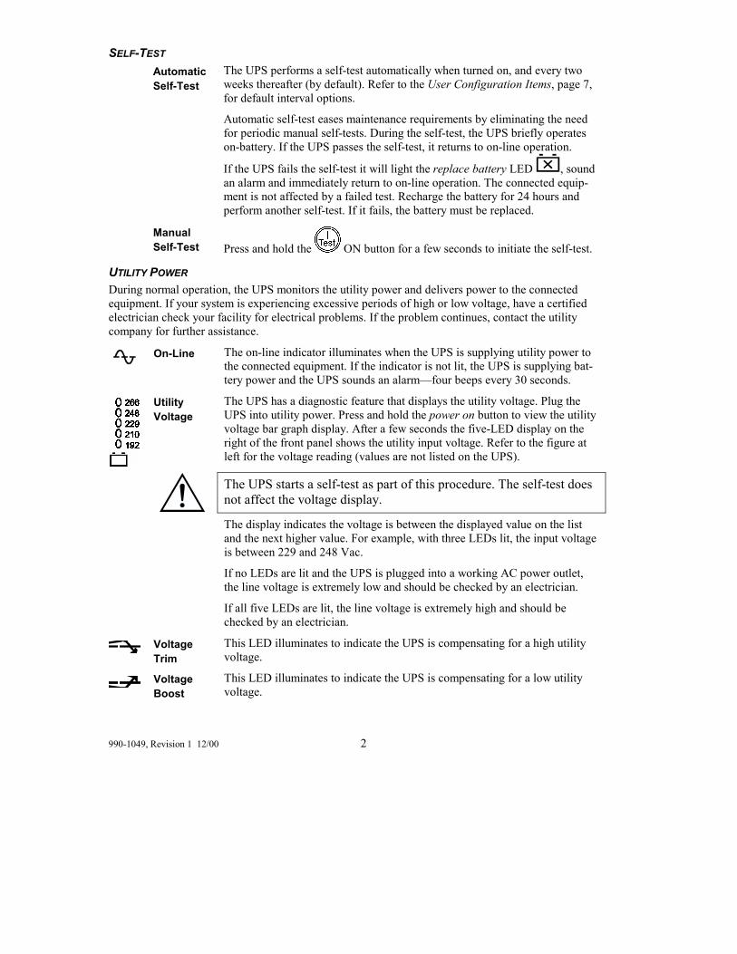
Utility Voltage
The UPS has a diagnostic feature that displays the utility voltage. Plug the UPS into utility power. Press and hold the power on button to view the utility voltage bar graph display. After a few seconds the five-LED display on the right of the front panel shows the utility input voltage. Refer to the figure at left for the voltage reading (values are not listed on the UPS).
The UPS starts a self-test as part of this procedure. The self-test does not affect the voltage display.
The display indicates the voltage is between the displayed value on the list and the next higher value. For example, with three LEDs lit, the input voltage is between 229 and 248 Vac.
If no LEDs are lit and the UPS is plugged into a working AC power outlet, the line voltage is extremely low and should be checked by an electrician.
If all five LEDs are lit, the line voltage is extremely high and should be checked by an electrician.
Voltage Trim
This LED illuminates to indicate the UPS is compensating for a high utility voltage.
Voltage Boost
This LED illuminates to indicate the UPS is compensating for a low utility voltage.

3 990-1049, Revision 1 12/00
BATTERY POWER If the utility power fails, the UPS can provide power to the connected equipment from its internal battery for a finite period. The UPS sounds an alarm�four beeps every 30 seconds�while operating on-battery power. The alarm stops when the UPS returns to on-line operation.
On-Battery Power
When the on-battery power indicator is lit the UPS is supplying battery power to the connected equipment.
Battery Charge
The five-LED display on the right of the front panel shows the present charge of the UPS battery as a percentage of the battery capacity. When all five LEDs are lit, the battery is fully charged. The LEDs extinguish, from top to bottom, as the battery capacity diminishes. Refer to the fig-ure at left for the battery capacity threshold (values are not listed on the UPS).
As a low battery warning, any LEDs illuminated (for the given capacity) flash and the UPS beeps. The low battery warning default setting can be changed from the rear panel or through the optional PowerChutePlus® software. Refer to Default Settings, page 4, in this manual.
Overload The UPS emits a sustained alarm tone and the LED illuminates when an
overload condition occurs (that is, when the connected equipment ex-ceeds the specified �maximum load�). The alarm remains on until the overload is removed.
The UPS continues to supply power as long as it is on-line and the breaker does not trip; but the UPS will not provide power from batteries in the event of a utility voltage interruption due to an overload condition.
Disconnect nonessential equipment from the UPS to eliminate the over-load. If a continuous overload occurs while the UPS is on-battery, the unit turns off output in order to protect the UPS from possible damage.
Replace Battery
Failure of a battery self-test causes the UPS to emit short beeps for one minute and the replace battery LED illuminates. The UPS repeats the alarm every five hours. Perform the self-test procedure after the battery has charged for 24 hours to confirm the replace battery condition. The alarm stops if the battery passes the self-test.
SHUTDOWN MODE (VIA SOFTWARE OR AN ACCESSORY) In shutdown mode, the UPS stops supplying power to the connected equipment, waiting for the re-turn of utility power. If there is no utility power present, external devices (such as servers) connected to the computer interface or the accessory slot can command the UPS to shut down. This normally is done to preserve battery capacity after the shutdown of protected servers. The UPS scrolls the front panel indicators sequentially in shutdown mode.
990-1049, Revision 1 12/00 4
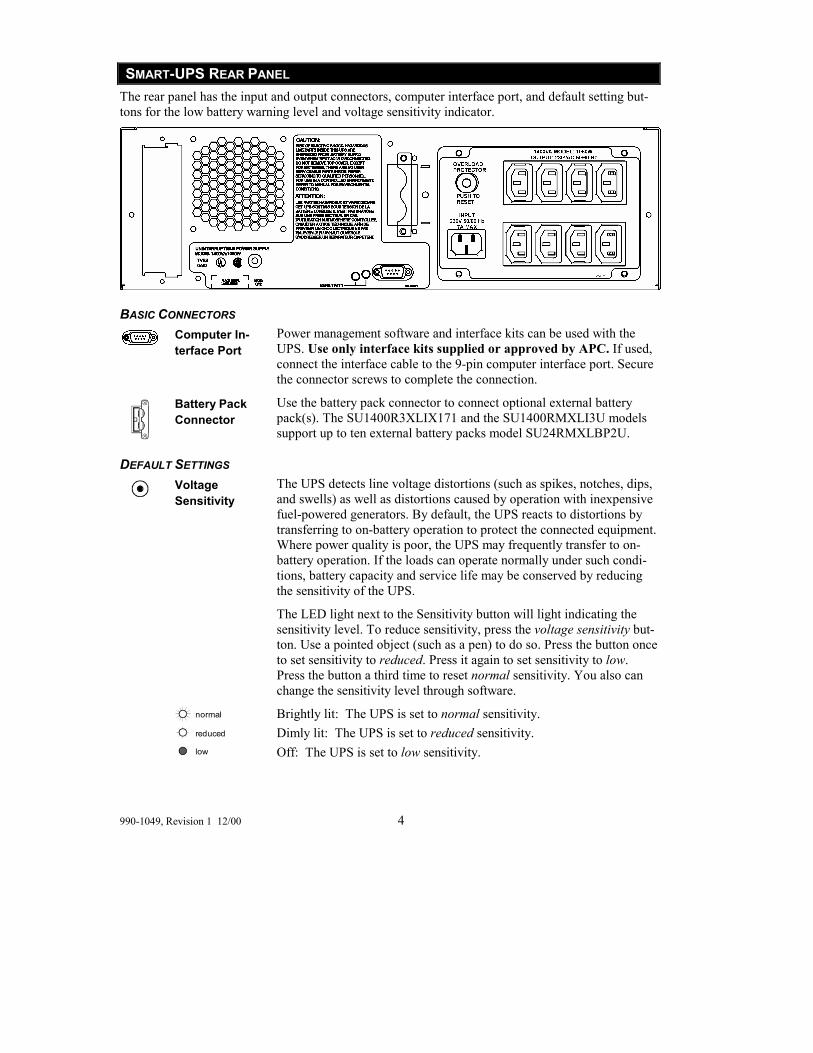
SMART-UPS REAR PANEL The rear panel has the input and output connectors, computer interface port, and default setting but-tons for the low battery warning level and voltage sensitivity indicator.
BASIC CONNECTORS
Computer In-terface Port
Power management software and interface kits can be used with the UPS. Use only interface kits supplied or approved by APC. If used, connect the interface cable to the 9-pin computer interface port. Secure the connector screws to complete the connection.
Battery Pack Connector
Use the battery pack connector to connect optional external battery pack(s). The SU1400R3XLIX171 and the SU1400RMXLI3U models support up to ten external battery packs model SU24RMXLBP2U.
DEFAULT SETTINGS
Voltage Sensitivity
The UPS detects line voltage distortions (such as spikes, notches, dips, and swells) as well as distortions caused by operation with inexpensive fuel-powered generators. By default, the UPS reacts to distortions by transferring to on-battery operation to protect the connected equipment. Where power quality is poor, the UPS may frequently transfer to on-battery operation. If the loads can operate normally under such condi-tions, battery capacity and service life may be conserved by reducing the sensitivity of the UPS.
The LED light next to the Sensitivity button will light indicating the sensitivity level. To reduce sensitivity, press the voltage sensitivity but-ton. Use a pointed object (such as a pen) to do so. Press the button once to set sensitivity to reduced. Press it again to set sensitivity to low. Press the button a third time to reset normal sensitivity. You also can change the sensitivity level through software.
normal
reduced
low
Brightly lit: The UPS is set to normal sensitivity. Dimly lit: The UPS is set to reduced sensitivity. Off: The UPS is set to low sensitivity.
5 990-1049, Revision 1 12/00
Low Battery Warning Level
The low battery warning beeps when there are approximately two min-utes of on-battery run time remaining. This may not be enough time to shut down some protected computer systems. The LED light next to the Sensitivity button will light indicat-ing the time remaining prior to shutdown. To change the warning inter-val default setting, press the voltage sensitivity button while pressing and holding the front-panel power on button.
2 min.
5 min.
7 min.
Brightly lit: The low battery warning interval is about two minutes. Dimly lit: The low battery warning interval is about five minutes. Off: The low battery warning interval is about seven minutes.
ON-BATTERY OPERATION The Smart-UPS switches to battery operation automatically when the utility power fails. While run-ning on-battery, an internal alarm sounds (periodic beeps). Press the power on button (front panel) to silence the UPS alarm (for the current alarm only).
If the utility power does not return, the UPS continues to supply power to the connected equipment until exhausted. While running on battery the UPS emits four beeps every thirty seconds. Two min-utes before the batteries final shutdown the UPS emits two beeps per second If using a computer, you must manually save your files and power down before the UPS turns off, unless you are using Pow-erChutePlus interface software that provides automatic, unattended shutdown.
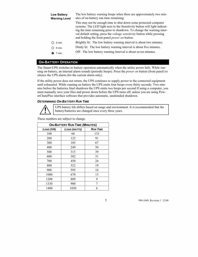
DETERMINING ON-BATTERY RUN TIME
UPS battery life differs based on usage and environment. It is recommended that the battery/batteries are changed once every three years.
These numbers are subject to change.
ON-BATTERY RUN TIME (MINUTES) LOAD (VA) LOAD (WATTS) RUN TIME
100 60 133 200 122 91 300 185 67 400 249 50 500 315 39 600 382 31 700 450 24 800 522 19 900 595 16
1000 670 13 1200 809 9 1330 900 7 1400 1050 6

990-1049, Revision 1 12/00 6
RUN TIME (MINUTES) WITH EXTERNAL BATTERY PACKS (SU24RMXLBP2U) # OF BATTERY
PACKS: LOAD (VA)
1 2 3 4 5 6 7 8 9 10
700 70 130 210 280 350 420 490 560 640 720 1200 32 65 100 150 190 230 270 310 350 400 1400 23 47 70 100 140 170 200 240 270 300
7 990-1049, Revision 1 12/00
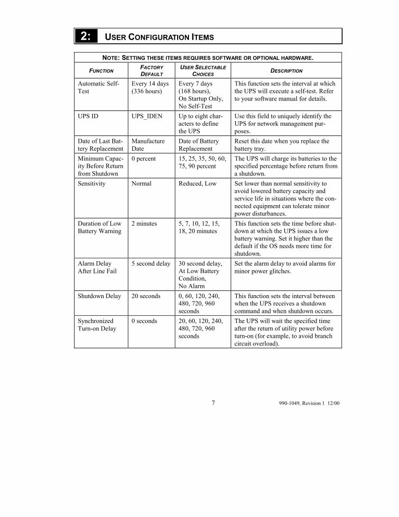
2: USER CONFIGURATION ITEMS
NOTE: SETTING THESE ITEMS REQUIRES SOFTWARE OR OPTIONAL HARDWARE.
FUNCTION FACTORY DEFAULT
USER SELECTABLE CHOICES DESCRIPTION
Automatic Self-Test
Every 14 days (336 hours)
Every 7 days (168 hours), On Startup Only, No Self-Test
This function sets the interval at which the UPS will execute a self-test. Refer to your software manual for details.
UPS ID UPS_IDEN Up to eight char-acters to define the UPS
Use this field to uniquely identify the UPS for network management pur-poses.
Date of Last Bat-tery Replacement
Manufacture Date
Date of Battery Replacement
Reset this date when you replace the battery tray.
Minimum Capac-ity Before Return from Shutdown
0 percent 15, 25, 35, 50, 60, 75, 90 percent
The UPS will charge its batteries to the specified percentage before return from a shutdown.
Sensitivity Normal Reduced, Low Set lower than normal sensitivity to avoid lowered battery capacity and service life in situations where the con-nected equipment can tolerate minor power disturbances.
Duration of Low Battery Warning
2 minutes 5, 7, 10, 12, 15, 18, 20 minutes
This function sets the time before shut-down at which the UPS issues a low battery warning. Set it higher than the default if the OS needs more time for shutdown.
Alarm Delay After Line Fail
5 second delay 30 second delay, At Low Battery Condition, No Alarm
Set the alarm delay to avoid alarms for minor power glitches.
Shutdown Delay 20 seconds 0, 60, 120, 240, 480, 720, 960 seconds
This function sets the interval between when the UPS receives a shutdown command and when shutdown occurs.
Synchronized Turn-on Delay
0 seconds 20, 60, 120, 240, 480, 720, 960 seconds
The UPS will wait the specified time after the return of utility power before turn-on (for example, to avoid branch circuit overload).
990-1049, Revision 1 12/00 8
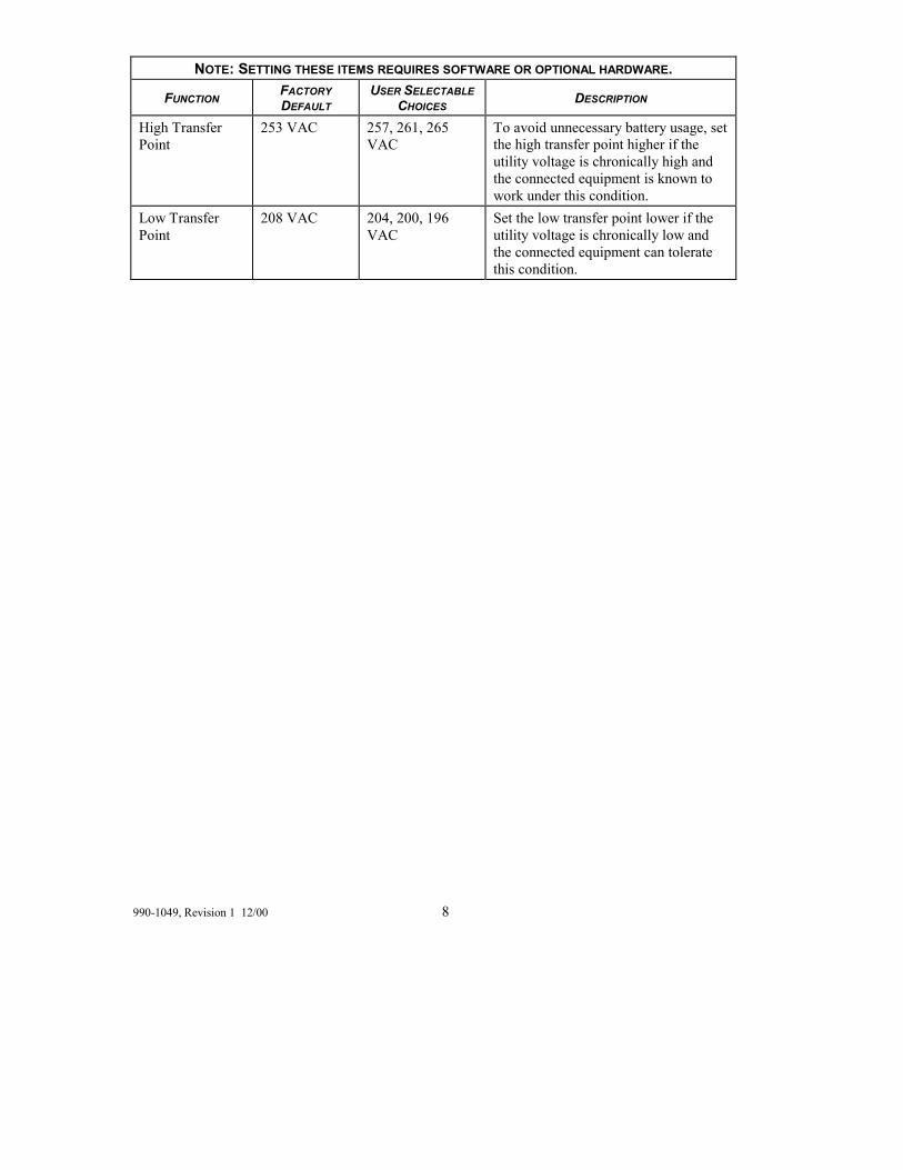
NOTE: SETTING THESE ITEMS REQUIRES SOFTWARE OR OPTIONAL HARDWARE.
FUNCTION FACTORY DEFAULT
USER SELECTABLE CHOICES DESCRIPTION
High Transfer Point
253 VAC 257, 261, 265 VAC
To avoid unnecessary battery usage, set the high transfer point higher if the utility voltage is chronically high and the connected equipment is known to work under this condition.
Low Transfer Point
208 VAC 204, 200, 196 VAC
Set the low transfer point lower if the utility voltage is chronically low and the connected equipment can tolerate this condition.

9 990-1049, Revision 1 12/00
3: STORAGE AND MAINTENANCE
STORAGE STORAGE CONDITIONS Store the UPS covered and flat (rack mount orientation) in a cool, dry location, with its battery fully charged. Disconnect any cables connected to the computer interface port to avoid unnecessary bat-tery drainage.
EXTENDED STORAGE At -15 to +30 °C (+5 to +86 °F), charge the UPS battery every six months. At +30 to +45 °C (+86 to +113 °F), charge the UPS battery every three months.
REPLACING THE BATTERY This UPS has an easy to replace, hot-swappable battery tray. Battery replacement is a safe procedure, isolated from electrical hazards. You may leave the UPS and the connected equipment on for the following procedure. See your dealer or contact APC for information on replacement battery car-tridges.
UNIT REPLACEMENT SHAPE
UPS SU1400RMXLI3U and UPS SU1400R3XLIX171 RBC25
Optional external battery pack SU24RMXLBP2U RBC26
BATTERY REPLACEMENT PROCEDURE
The battery is accessible from the front of the UPS. This procedure requires a Phillips head screwdriver.
1. Face the front of the UPS to remove the bezel. Use both hands and grasp the finger clips on either side of the bezel. Pull toward you. The bezel will unsnap. Set the bezel aside.
2. Use a screwdriver to remove the two battery door screws and open the door (hinged panel).

990-1049, Revision 1 12/00 10
3. To disconnect the battery, take out the white cord that is tucked into the space above the battery. �. This cord serves as a handle for the connector. Grasp the cord and pull firmly toward you.
4. Be careful during this step�the battery is heavy. Pull the battery out of the UPS by pulling the clear label �, not the white cord. (The battery consists of a string of four batteries. The white cord is connected to the bat-tery leads, not the body of the battery.)
Once the battery is disconnected, the loads are not protected from power out-ages.
5. The plug on the new battery is taped to the side of the battery. Remove this tape allowing the plug and the at-tached white cord and battery cables to come to the front of the battery.
6. Supporting the new battery on the bottom, align it with the battery door opening and slide it into the compart-ment.
7. Locate the UPS battery connector jack � to the right of the battery tray.
8. To connect the battery cable plug and the battery jack, push the plug into the jack so the metal pieces inside each part are touching. Press firmly to ensure a tight connection. You will hear a �snap� when the connector is seated properly.
9. Tuck the white cord and the battery cables into the space above the UPS battery.
10. Close the battery door and replace the two screws re-moved in Step 2.
11. Hold the bezel with the cutout section on the right. Align the tabs on the side of the bezel with the slots on the front of the UPS and gently snap it into place.
Batteries must be recycled. Deliver the battery to an appropriate recycling facility or ship it to the supplier in the new battery�s packing material. See the new battery in-structions for more information.
��
�
11 990-1049, Revision 1 12/00
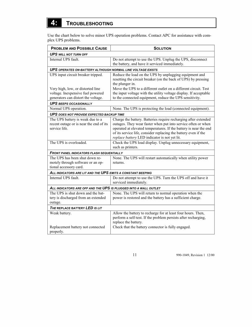
4: TROUBLESHOOTING
Use the chart below to solve minor UPS operation problems. Contact APC for assistance with com-plex UPS problems.
PROBLEM AND POSSIBLE CAUSE SOLUTION UPS WILL NOT TURN OFF Internal UPS fault. Do not attempt to use the UPS. Unplug the UPS, disconnect
the battery, and have it serviced immediately. UPS OPERATES ON-BATTERY ALTHOUGH NORMAL LINE VOLTAGE EXISTS UPS input circuit breaker tripped. Reduce the load on the UPS by unplugging equipment and
resetting the circuit breaker (on the back of UPS) by pressing the plunger in.
Very high, low, or distorted line voltage. Inexpensive fuel powered generators can distort the voltage.
Move the UPS to a different outlet on a different circuit. Test the input voltage with the utility voltage display. If acceptable to the connected equipment, reduce the UPS sensitivity.
UPS BEEPS OCCASIONALLY Normal UPS operation. None. The UPS is protecting the load (connected equipment). UPS DOES NOT PROVIDE EXPECTED BACKUP TIME The UPS battery is weak due to a recent outage or is near the end of its service life.
Charge the battery. Batteries require recharging after extended outages. They wear faster when put into service often or when operated at elevated temperatures. If the battery is near the end of its service life, consider replacing the battery even if the replace battery LED indicator is not yet lit.
The UPS is overloaded. Check the UPS load display. Unplug unnecessary equipment, such as printers.
FRONT PANEL INDICATORS FLASH SEQUENTIALLY The UPS has been shut down re-motely through software or an op-tional accessory card.
None. The UPS will restart automatically when utility power returns.
ALL INDICATORS ARE LIT AND THE UPS EMITS A CONSTANT BEEPING Internal UPS fault. Do not attempt to use the UPS. Turn the UPS off and have it
serviced immediately. ALL INDICATORS ARE OFF AND THE UPS IS PLUGGED INTO A WALL OUTLET The UPS is shut down and the bat-tery is discharged from an extended outage.
None. The UPS will return to normal operation when the power is restored and the battery has a sufficient charge.
THE REPLACE BATTERY LED IS LIT Weak battery. Allow the battery to recharge for at least four hours. Then,
perform a self-test. If the problem persists after recharging, replace the battery.
Replacement battery not connected properly.
Check that the battery connector is fully engaged.
990-1049, Revision 1 12/00 12
SERVICE If the UPS requires service do not return it to the dealer. Instead follow these steps:
1. Review the problems discussed in Troubleshooting to eliminate common problems.
2. Verify that no circuit breakers are tripped. A tripped circuit breaker is the most common UPS problem.
3. If the problem persists, refer to Contacting APC, next page.
�� Note the model number of the battery pack, the serial number, and the date purchased. If you call Customer Service a technician will ask you to describe the problem and try to solve it over the phone, if possible. If this is not possible the technician will issue a Returned Ma-terial Authorization Number (RMA#).
�� If the UPS is under warranty, repairs are free. If not, there is a repair charge.
4. Pack the UPS in its original packaging. If the original packing is not available, ask customer service about obtaining a new set.
Pack the UPS properly to avoid damage in transit. Never use Styrofoam beads for packaging. Damage sustained in transit is not covered under warranty.
Refer to the Installation Manual for important shipping instructions.
5. Mark the RMA# on the outside of the package.
6. Return the UPS by insured, prepaid carrier to the address given to you by Customer Service.

13 990-1049, Revision 1 12/00
5: CONTACT, REGULATORY, AND WARRANTY INFORMATION
CONTACTING APC Refer to the information provided at the APC Internet site:
http://www.apcc.com/support/contact
If you ordered a Smart-UPS SU1400R3XLIX171 unit, please refer to the red adden-dum sheet (part number 990-1023A) for contact information.
REGULATORY AGENCY APPROVALS
N 394
B
ME 61
This is a Class A product. In a domestic environment this product may cause radio interference, in which case the user may be required to take corrective actions.
geprüfte Sicherheit
990-1049, Revision 1 12/00 14
LIMITED WARRANTY American Power Conversion (APC) warrants its products to be free from defects in materials and workmanship for a period of two years from the date of purchase. Its obligation under this warranty is limited to repairing or replacing, at its own sole option, any such defective products. To obtain service under warranty you must obtain a Returned Material Authorization (RMA) number from cus-tomer support. Products must be returned with transportation charges prepaid and must be accompa-nied by a brief description of the problem encountered and proof of date and place of purchase. This warranty does not apply to equipment that has been damaged by accident, negligence, or misapplica-tion or has been altered or modified in any way. This warranty applies only to the original purchaser who must have properly registered the product within 10 days of purchase.
EXCEPT AS PROVIDED HEREIN, AMERICAN POWER CONVERSION MAKES NO WAR-RANTIES, EXPRESSED OR IMPLIED, INCLUDING WARRANTIES OF MERCHANTABILITY AND FITNESS FOR A PARTICULAR PURPOSE. Some states do not permit limitation or exclu-sion of implied warranties; therefore, the aforesaid limitation(s) or exclusion(s) may not apply to the purchaser.
EXCEPT AS PROVIDED ABOVE, IN NO EVENT WILL APC BE LIABLE FOR DIRECT, IN-DIRECT, SPECIAL, INCIDENTAL, OR CONSEQUENTIAL DAMAGES ARISING OUT OF THE USE OF THIS PRODUCT, EVEN IF ADVISED OF THE POSSIBILITY OF SUCH DAM-AGE. Specifically, APC is not liable for any costs, such as lost profits or revenue, loss of equipment, loss of use of equipment, loss of software, loss of data, costs of substitutes, claims by third parties, or otherwise.
Entire contents copyright © 2001 by American Power Conversion Corporation. All rights reserved. Reproduction in whole or in part without permission is prohibited.
APC, Smart-UPS, and PowerChute are registered trademarks of American Power Conversion Corpo-ration. All other trademarks are the property of their respective owners.