operation manual - cie-group · 8x8 audio matrix system wwelcomeelcome a personal welcome to you...
TRANSCRIPT
Operation Manual
8X8 Audio Matrix System
PX/RM/LM-8000
8X8 AUDIO MATRIX SYSTEM
WelcomeWelcomeA personal welcome to you from the management and employees of Inter-M
All of the co-workers here at Inter-M are dedicated to providing excellent products with inherently good value,and we are delighted you have purchased one of our products.
We sincerely trust this product will provide years of satisfactory service, but if anything is not to your completesatisfaction, we will endeavor to make things right.
Welcome to Inter-M, and thank you for becoming part of our worldwide extended family!
* It can be heated up if you use this product in closed box or ill-ventilated place.
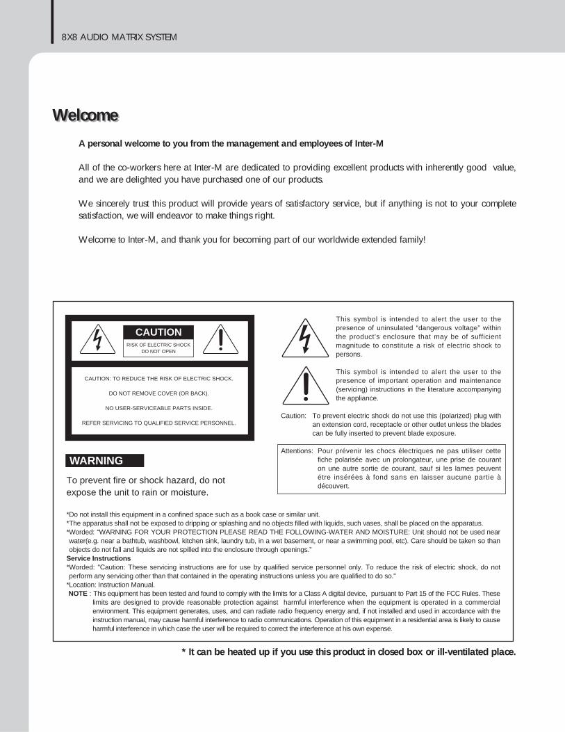
RISK OF ELECTRIC SHOCKDO NOT OPEN
CAUTION
CAUTION: TO REDUCE THE RISK OF ELECTRIC SHOCK.
DO NOT REMOVE COVER (OR BACK).
NO USER-SERVICEABLE PARTS INSIDE.
REFER SERVICING TO QUALIFIED SERVICE PERSONNEL.
WARNING
To prevent fire or shock hazard, do notexpose the unit to rain or moisture.
*Do not install this equipment in a confined space such as a book case or similar unit.*The apparatus shall not be exposed to dripping or splashing and no objects filled with liquids, such vases, shall be placed on the apparatus.*Worded: “WARNING FOR YOUR PROTECTION PLEASE READ THE FOLLOWING-WATER AND MOISTURE: Unit should not be used nearwater(e.g. near a bathtub, washbowl, kitchen sink, laundry tub, in a wet basement, or near a swimming pool, etc). Care should be taken so thanobjects do not fall and liquids are not spilled into the enclosure through openings.”
Service Instructions*Worded: "Caution: These servicing instructions are for use by qualified service personnel only. To reduce the risk of electric shock, do notperform any servicing other than that contained in the operating instructions unless you are qualified to do so."
*Location: Instruction Manual.NOTE : This equipment has been tested and found to comply with the limits for a Class A digital device, pursuant to Part 15 of the FCC Rules. These
limits are designed to provide reasonable protection against harmful interference when the equipment is operated in a commercialenvironment. This equipment generates, uses, and can radiate radio frequency energy and, if not installed and used in accordance with theinstruction manual, may cause harmful interference to radio communications. Operation of this equipment in a residential area is likely to causeharmful interference in which case the user will be required to correct the interference at his own expense.
This symbol is intended to alert the user to thepresence of uninsulated “dangerous voltage” withinthe product’s enclosure that may be of sufficientmagnitude to constitute a risk of electric shock topersons.
This symbol is intended to alert the user to thepresence of important operation and maintenance(servicing) instructions in the literature accompanyingthe appliance.
Caution: To prevent electric shock do not use this (polarized) plug withan extension cord, receptacle or other outlet unless the bladescan be fully inserted to prevent blade exposure.
Attentions: Pour prévenir les chocs électriques ne pas utiliser cettefiche polarisée avec un prolongateur, une prise de couranton une autre sortie de courant, sauf si les lames peuventétre insérées à fond sans en laisser aucune partie àdécouvert.
8X8 AUDIO MATRIX SYSTEM
1PX-8000/RM-8000/LM-8000
ContentsContentsUnpacking .......................................................................................................................................2
InstallationEnvironment....................................................................................................................................3Important Safety Instructions.............................................................................................................3
Description.......................................................................................................................................4
Features............................................................................................................................................4Accessories.....................................................................................................................................4
PanelPX-8000 Front Panel........................................................................................................................5PX-8000 Rear Panel ........................................................................................................................7RM-8000 Front Panel ......................................................................................................................9RM-8000 Rear Panel .....................................................................................................................10LM-8000 Front Panel .....................................................................................................................11LM-8000 Rear Panel......................................................................................................................12
Operation ......................................................................................................................................13
Connections ...................................................................................................................................19
Block Diagram ..............................................................................................................................20
Specifications ................................................................................................................................21
ServiceProcedures....................................................................................................................................22Schematic .....................................................................................................................................22Parts List .......................................................................................................................................22
Variations and Options ...............................................................................................................22
Warranty .......................................................................................................................................22
Short Form Instructions
Unpacking
8X8 AUDIO MATRIX SYSTEM
2 PX-8000/RM-8000/LM-8000
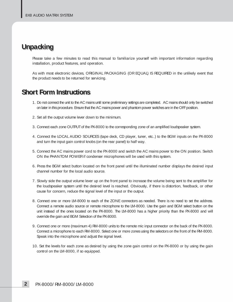
UnpackingPlease take a few minutes to read this manual to familiarize yourself with important information regardinginstallation, product features, and operation.
As with most electronic devices, ORIGINAL PACKAGING (OR EQUAL) IS REQUIRED in the unlikely event thatthe product needs to be returned for servicing.
Short Form Instructions1. Do not connect the unit to the AC mains until some preliminary settings are completed. AC mains should only be switched
on later in this procedure. Ensure that the AC mains power and phantom power switches are in the OFF position.
2. Set all the output volume lever down to the minimum.
3. Connect each zone OUTPUT of the PX-8000 to the corresponding zone of an amplified loudspeaker system.
4. Connect the LOCAL AUDIO SOURCES (tape deck, CD player, tuner, etc..) to the BGM inputs on the PX-8000and turn the input gain control knobs (on the rear panel) to half way.
5. Connect the AC mains power cord to the PX-8000 and switch the AC mains power to the ON position. SwitchON the PHANTOM POWER if condenser microphones will be used with this system.
6. Press the BGM select button located on the front panel until the illuminated number displays the desired inputchannel number for the local audio source.
7. Slowly side the output volume lever up on the front panel to increase the volume being sent to the amplifier forthe loudspeaker system until the desired level is reached. Obviously, if there is distortion, feedback, or othercause for concern, reduce the signal level of the input or the output.
8. Connect one or more LM-8000 to each of the ZONE connectors as needed. There is no need to set the address.Connect a remote audio source or remote microphone to the LM-8000. Use the gain and BGM select button on theunit instead of the ones located on the PX-8000. The LM-8000 has a higher priority than the PX-8000 and willoverride the gain and BGM Selection of the PX-8000.
9. Connect one or more (maximum 4) RM-8000 units to the remote mic input connector on the back of the PX-8000.Connect a microphone to each RM-8000. Select one or more zones using the selectors on the front of the RM-8000.Speak into the microphone and adjust the signal level.
10. Set the levels for each zone as desired by using the zone gain control on the PX-8000 or by using the gaincontrol on the LM-8000, if so equipped.
8X8 AUDIO MATRIX SYSTEM
3PX-8000/RM-8000/LM-8000
InstallationInstallationEnvironmentNever place this product in an environment which could alter its performance or reduce its service life. Suchenvironments usually include high levels of heat, dust, moisture, and vibration.
Important Safety Instructions1. Read these instructions.2. Keep these instructions.3. Heed all warnings.4. Follow all instructions.5. Do not use this apparatus near water.6. Clean only with dry cloth.7. Do not block any ventilation openings. Install in accordance with the manufacturer’s instructions.8. Do not install near any heat sources such as radiators, heat registers, stoves, or other apparatus (including
amplifiers) that produce heat.9. Do not defeat the safety purpose of the polarized or grounding-type plug. A polarized plug has two blades
with one wider than the other. A grounding type plug has two blades and a third grounding prong. The wideblade or the third prong are provided for your safety. If the provided plug does not fit into your outlet, consultan electrician for replacement of the obsolete outlet.
10. Protect the power cord from being walked on or pinched particularly at plugs, convenience receptacles, andthe point where they exit from the apparatus.
11. Only use attachments/accessories specified by the manufacturer.12. Use only with the cart, stand, tripod, bracket, or table specified by the manufacturer, or sold with the apparatus.
When a cart is used, use caution when moving the cart/apparatus combination to avoid injury from tip-over.13. Unplug this apparatus during lightning storms or when unused for long periods of time.14. Refer all servicing to qualified service personnel. Servicing is required when the
apparatus has been damaged in any way, such as power-supply cord or plug isdamaged, liquid has been spilled or objects have fallen into the apparatus, theapparatus has been exposed to rain or moisture, does not operate normally, or hasbeen dropped.
- AVOID EXCESSIVE HEAT, HUMIDITY, DUST AND VIBRATIONKeep the unit away from locations where it is likely to be exposed to high temperatures or humidity-such as near radiators, stoves,etc. Also avoid locations which are subject to excessive dust accumulation, or to vibration that could cause mechanical damage.
- AVOID PHYSICAL SHOCKSStrong physical shocks to the unit may cause damage. Handle the unit with care.
- DO NOT OPEN THE CASE OR ATTEMPT REPAIRS OR MODIFICATIONS YOURSELFThis product contains no user-serviceable parts. Refer all maintenance to qualified Inter-M service personnel.Opening the case and/or tampering with internal circuitry voids the warranty.
- ALWAYS POWER OFF BEFORE MAKING CONNECTIONSAlways turn the AC mains OFF before connecting or disconnecting cables. This is important to prevent damage tothe unit itself as well as other connected equipment.
- HANDLE CABLES CAREFULLYAlways plug and unplug cables (including the AC mains power cord) by gripping the connector, not the cord.
- CLEAN WITH A SOFT DRY CLOTHNever use solvents such as benzine or paint thinner to clean the unit. Wipe clean with a soft, dry cloth.
S3125A
S3125A
8X8 AUDIO MATRIX SYSTEM
4 PX-8000/RM-8000/LM-8000
DescriptionDescriptionThe PX-8000 and related components provides the latest technology combined with ease of operation tocreate a system which offers enormous capability and flexibility. Local audio sources may be sent to anycombination of up to eight remote zones and do so with either local or remote control.
This type of flexibility makes this product ideal for any type of multi-zone system including hotels, airports,casinos, hospitals, conference centers, and restaurants.
A wide assortment of remote devices insures that the right amount of control is located in the correctlocations throughout a facility.
FeaturesFeatures- New concept of audio matrix system for public addressing and emergency broadcasting- Various audio inputs (BGM, Remote MIC, Local Wall Mount MIC & BGM, Paging MIC)- Individual BGM broadcasting and area selection broadcasting to 8 output areas- Unlimited expansion of output area in link with Main System (PX-8000)- Convenient priority broadcasting (Paging MIC > DRP > RM-8000 > LM-8000 > BGM)- Previous hearing of BGM using a monitor speaker- Convenient installation and construction without need of ID setting (RM-8000, LM-8000)- Voice recording by using Record & Playback IC and automatic play in link with fire contact- Lump change of BGM for all outputs (available in link system)- Adoption of RS-422 communication method to support a long distance- Selection of various Chime broadcastings for MIC broadcasting (PRE/POST)- Capable of adjusting individual tone(bass/treble) in every output area- Convenient connection with 8CH Power Amp through adoption of lump output terminal- Adoption of I/O signal level display
Accessories3 Pin Terminal Block 8pcs9 Pin Terminal Block 1 pcsOperation Manual 1pcs.Rack Mount Screw & Washer 4pcsFoot & Screw 4pcs
8X8 AUDIO MATRIX SYSTEM
5PX-8000
PX-8000 Front PanelPX-8000 Front Panel
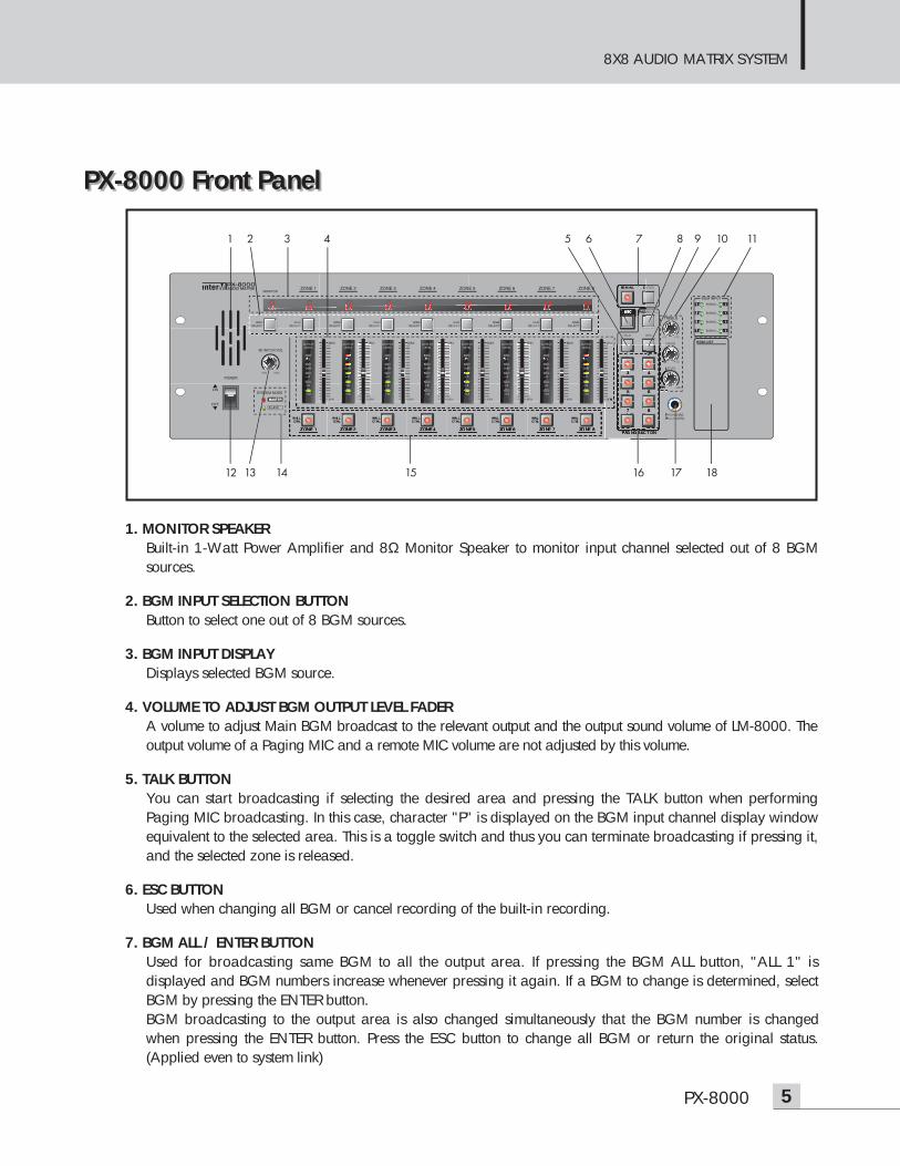
1. MONITOR SPEAKERBuilt-in 1-Watt Power Amplifier and 8Ω Monitor Speaker to monitor input channel selected out of 8 BGMsources.
2. BGM INPUT SELECTION BUTTONButton to select one out of 8 BGM sources.
3. BGM INPUT DISPLAYDisplays selected BGM source.
4. VOLUME TO ADJUST BGM OUTPUT LEVEL FADER A volume to adjust Main BGM broadcast to the relevant output and the output sound volume of LM-8000. Theoutput volume of a Paging MIC and a remote MIC volume are not adjusted by this volume.
5. TALK BUTTONYou can start broadcasting if selecting the desired area and pressing the TALK button when performingPaging MIC broadcasting. In this case, character "P" is displayed on the BGM input channel display windowequivalent to the selected area. This is a toggle switch and thus you can terminate broadcasting if pressing it,and the selected zone is released.
6. ESC BUTTONUsed when changing all BGM or cancel recording of the built-in recording.
7. BGM ALL / ENTER BUTTONUsed for broadcasting same BGM to all the output area. If pressing the BGM ALL button, "ALL 1" isdisplayed and BGM numbers increase whenever pressing it again. If a BGM to change is determined, selectBGM by pressing the ENTER button.BGM broadcasting to the output area is also changed simultaneously that the BGM number is changedwhen pressing the ENTER button. Press the ESC button to change all BGM or return the original status.(Applied even to system link)
1
12 14 15 16 17 1813
2 3 4 7 8 9 10 115 6
8X8 AUDIO MATRIX SYSTEM
6 PX-8000
8. PAGING ALL BUTTONIf broadcasting a Paging MIC to all output areas, firstly pressing this button before pressing the TALK buttonenables to select all the output areas. Buttons of all the Paging broadcasting areas turn on. If pressing thebuttons again, the relevant function is released. (Applied even to system link)
9. REC BUTTONEnters into the Recording Standby Mode if pressing the REC button. Check that alphabet character called as "-record-" is displayed. (Recording mode is released if pressing the ESC button in theRecording Standby Mode. Press the REC button to release during recording.) If recording standby is completed, start recording by pressing this button lengthily (about a second). Checkthat recording is being done while the first character and ending character "-" from the "-RECORD-" rotate.If recording is completed, end by pressing the REC button. (Maximum recording time is 30sec.)
10. TREBLE/BASS/LEVEL ADJUSTMENT VOLUMEAdjusts volume and tone when broadcasting MIC and when recording built-in DRP IC.
11. BGM INPUT LEDA LED of the input channel, where BGM signal comes from, turns on.
12. POWER SWITCHA switch to apply power supply to the system
13. MONITOR SPEAKER VOLUMEA volume to adjust BGM volume output to the Monitor Speaker
14. MASTER/SLAVE LEDDisplays mode in link of PX-8000. This turns on depending on the status of the rear Link Mode switch.
15. WALL MOUNT CONTROLLER (LM-8000) ENABLE BUTTONThis is a toggle switch to select whether the WALL Controller (LM-8000) connected to each output zone isenable/disable. If the button turns on, selection of BGM and adjustment of BGM output volume are done onlyby LM-8000. If the button turns off, the related right is transferred to PX-8000. In this case, volume of theoutput area is returned to the original status. Even for PX-8000 powering ON/OFF, the right is automaticallymemorized.
16. PAGING ZONE SELECTION BUTTONButton to select the desired output area when broadcasting using a paging MIC.Has a toggle function and the selected button turns on.
17. PAGING MICAn input jack to connect a Paging MIC. It is recommended to use a balanced MIC.
18. BGM LISTA position to write name for user to easily discern each BGM input source.
8X8 AUDIO MATRIX SYSTEM
7PX-8000
PX-8000 Rear PanelPX-8000 Rear Panel
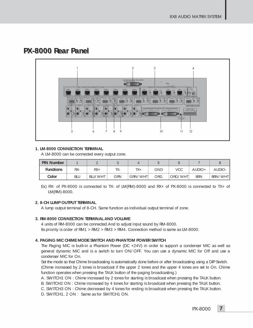
1. LM-8000 CONNECTION TERMINALA LM-8000 can be connected every output zone.
Ex) RX- of PX-8000 is connected to TX- of LM(RM)-8000 and RX+ of PX-8000 is connected to TX+ ofLM(RM)-8000.
2. 8-CH LUMP OUTPUT TERMINALA lump output terminal of 8-CH. Same function as individual output terminal of zone.
3. RM-8000 CONNECTION TERMINAL AND VOLUME4 units of RM-8000 can be connected.And to adjust input sound by RM-8000.Its priority is order of RM1 > RM2 > RM3 > RM4. Connection method is same as LM-8000.
4. PAGING MIC CHIME MODE SWITCH AND PHANTOM POWER SWITCHThe Paging MIC is built-in a Phantom Power (DC +24V) in order to support a condenser MIC as well asgeneral dynamic MIC and is a switch to turn ON/OFF. You can use a dynamic MIC for Off and use acondenser MIC for On.Set the mode so that Chime broadcasting is automatically done before or after broadcasting using a DIP Switch.(Chime increased by 2 tones is broadcast if the upper 2 tones and the upper 4 tones are set to On. Chimefunction operates when pressing the TALK button of the paging broadcasting.) A. SWITCH1 ON : Chime increased by 2 tones for starting is broadcast when pressing the TALK button.B. SWITCH2 ON : Chime increased by 4 tones for starting is broadcast when pressing the TALK button. C. SWITCH3 ON : Chime decreased by 4 tones for ending is broadcast when pressing the TALK button. D. SWITCH1, 2 ON : Same as for SWITCH1 ON.
1 2 3 4
5 6 8 9 10 11 127
PIN Number 1 2 3 4 5 6 7 8
Functions RX- RX+ TX- TX+ GND VCC AUDIO+ AUDIO-
Color BLU BLU/WHT GRN GRN/WHT ORG ORG/WHT BRN BRN/WHT
8X8 AUDIO MATRIX SYSTEM
8 PX-8000
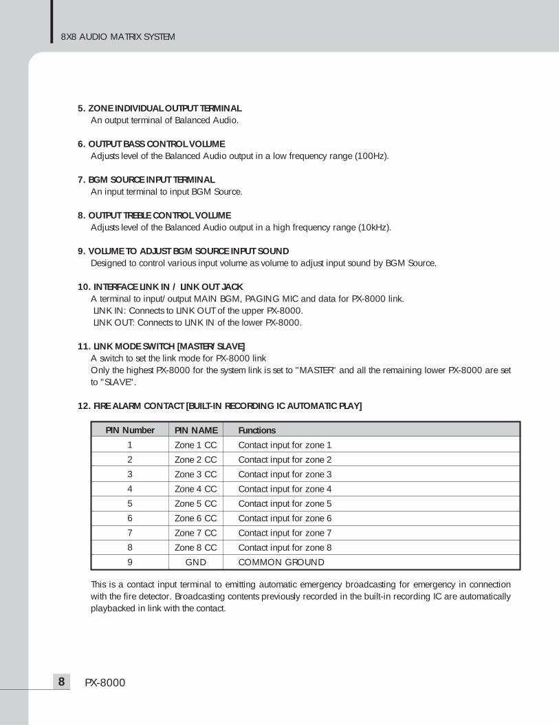
5. ZONE INDIVIDUAL OUTPUT TERMINALAn output terminal of Balanced Audio.
6. OUTPUT BASS CONTROL VOLUMEAdjusts level of the Balanced Audio output in a low frequency range (100Hz).
7. BGM SOURCE INPUT TERMINAL An input terminal to input BGM Source.
8. OUTPUT TREBLE CONTROL VOLUME Adjusts level of the Balanced Audio output in a high frequency range (10kHz).
9. VOLUME TO ADJUST BGM SOURCE INPUT SOUNDDesigned to control various input volume as volume to adjust input sound by BGM Source.
10. INTERFACE LINK IN / LINK OUT JACKA terminal to input/output MAIN BGM, PAGING MIC and data for PX-8000 link.LINK IN: Connects to LINK OUT of the upper PX-8000.LINK OUT: Connects to LINK IN of the lower PX-8000.
11. LINK MODE SWITCH [MASTER/SLAVE]A switch to set the link mode for PX-8000 linkOnly the highest PX-8000 for the system link is set to "MASTER" and all the remaining lower PX-8000 are setto "SLAVE".
12. FIRE ALARM CONTACT [BUILT-IN RECORDING IC AUTOMATIC PLAY]
This is a contact input terminal to emitting automatic emergency broadcasting for emergency in connectionwith the fire detector. Broadcasting contents previously recorded in the built-in recording IC are automaticallyplaybacked in link with the contact.
PIN Number
1
2
3
4
5
6
7
8
9
PIN NAME Functions
Zone 1 CC Contact input for zone 1
Zone 2 CC Contact input for zone 2
Zone 3 CC Contact input for zone 3
Zone 4 CC Contact input for zone 4
Zone 5 CC Contact input for zone 5
Zone 6 CC Contact input for zone 6
Zone 7 CC Contact input for zone 7
Zone 8 CC Contact input for zone 8
GND COMMON GROUND
REMOTE MIC STATION
9RM-8000
RM-8000 Front PanelRM-8000 Front Panel
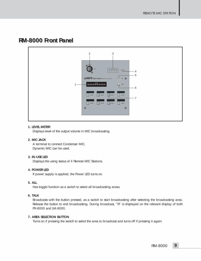
1. LEVEL METERDisplays level of the output volume in MIC broadcasting.
2. MIC JACKA terminal to connect Condenser MIC.Dynamic MIC can be used.
3. IN-USE LED Displays the using status of 4 Remote MIC Stations.
4. POWER LEDIf power supply is applied, the Power LED turns on.
5. ALL Has toggle function as a switch to select all broadcasting areas.
6. TALKBroadcasts with the button pressed, as a switch to start broadcasting after selecting the broadcasting area.Release the button to end broadcasting. During broadcast, "R" is displayed on the relevant display of bothPX-8000 and LM-8000.
7. AREA SELECTION BUTTONTurns on if pressing the switch to select the area to broadcast and turns off if pressing it again.
2 3
7
61
54
REMOTE MIC STATION
10 RM-8000
RM-8000 Rear PanelRM-8000 Rear Panel
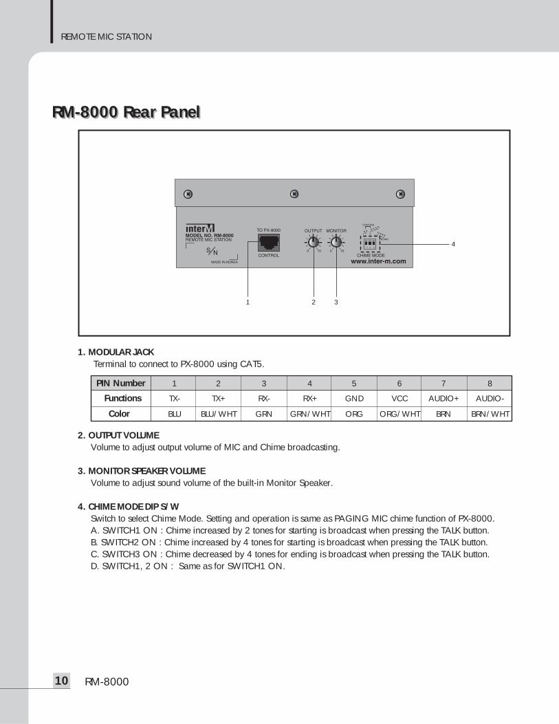
1. MODULAR JACKTerminal to connect to PX-8000 using CAT5.
2. OUTPUT VOLUMEVolume to adjust output volume of MIC and Chime broadcasting.
3. MONITOR SPEAKER VOLUMEVolume to adjust sound volume of the built-in Monitor Speaker.
4. CHIME MODE DIP S/WSwitch to select Chime Mode. Setting and operation is same as PAGING MIC chime function of PX-8000.A. SWITCH1 ON : Chime increased by 2 tones for starting is broadcast when pressing the TALK button.B. SWITCH2 ON : Chime increased by 4 tones for starting is broadcast when pressing the TALK button. C. SWITCH3 ON : Chime decreased by 4 tones for ending is broadcast when pressing the TALK button. D. SWITCH1, 2 ON : Same as for SWITCH1 ON.
4
321
PIN Number 1 2 3 4 5 6 7 8
Functions TX- TX+ RX- RX+ GND VCC AUDIO+ AUDIO-
Color BLU BLU/WHT GRN GRN/WHT ORG ORG/WHT BRN BRN/WHT
REMOTE CONTROL WITH AUDIO IN
11LM-8000
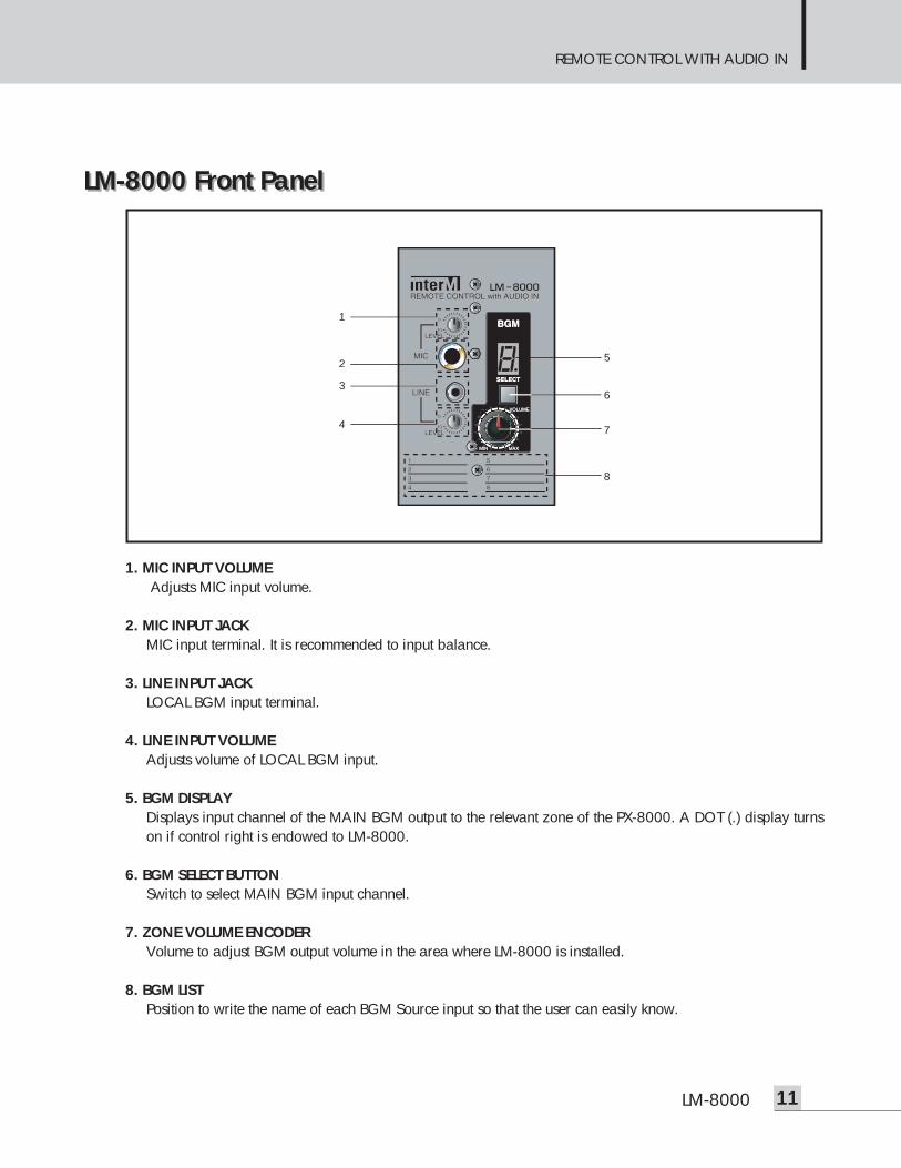
LM-8000 Front PanelLM-8000 Front Panel
1. MIC INPUT VOLUMEAdjusts MIC input volume.
2. MIC INPUT JACKMIC input terminal. It is recommended to input balance.
3. LINE INPUT JACKLOCAL BGM input terminal.
4. LINE INPUT VOLUMEAdjusts volume of LOCAL BGM input.
5. BGM DISPLAYDisplays input channel of the MAIN BGM output to the relevant zone of the PX-8000. A DOT (.) display turnson if control right is endowed to LM-8000.
6. BGM SELECT BUTTON Switch to select MAIN BGM input channel.
7. ZONE VOLUME ENCODERVolume to adjust BGM output volume in the area where LM-8000 is installed.
8. BGM LISTPosition to write the name of each BGM Source input so that the user can easily know.
1
2
3
4
5
6
7
8
REMOTE CONTROL WITH AUDIO IN
12 LM-8000
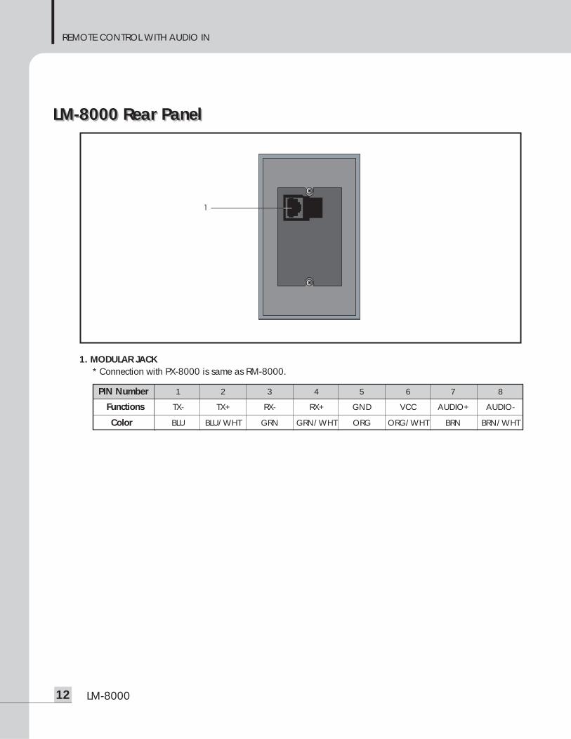
LM-8000 Rear PanelLM-8000 Rear Panel
1. MODULAR JACK* Connection with PX-8000 is same as RM-8000.
1
PIN Number 1 2 3 4 5 6 7 8
Functions TX- TX+ RX- RX+ GND VCC AUDIO+ AUDIO-
Color BLU BLU/WHT GRN GRN/WHT ORG ORG/WHT BRN BRN/WHT
8X8 AUDIO MATRIX SYSTEM
13PX-8000/RM-8000/LM-8000
Operation Operation 1. Priority of PX/RM/LM-8000 Broadcasting
This system broadcasts according to following priority:PAGING MIC > FIRE ALARM (REC&PLAY IC) > RM-8000 MIC > LM-8000 > PX-8000 BGM- The lower priority of broadcasting is shut off if broadcasting the upper priority of RM-8000, and output
is done if the upper priority of broadcasting.- RM-8000 has the priority of RM1 > RM2 > RM3 > RM4. However, the RM-8000 firstly starting
broadcasting has the priority because non-broadcasting area has the same priority.- The PX-8000 BGM broadcasting becomes slowly MUTE if Local broadcasting is done in the LM-8000
during the PX-8000 BGM broadcasting.
2. PX-8000 BGM Broadcasting 1 (Single operation)- Connects a BGM source unit to broadcast to the rear BGM input terminal.- The LED equivalent to the front BGM input turns on if input signal comes.- Capable of performing previous hearing by selecting the input channel with the front monitor speaker. - Select Input using the BGM Selection button in the desired output area and then adjust the output volume.
BGM display of the LM-8000 connected to the relevant area is also changed when changing BGM. Capable of selecting the desired BGM broadcasting by connecting up to 8 BGM source units andbroadcasting to the output area.
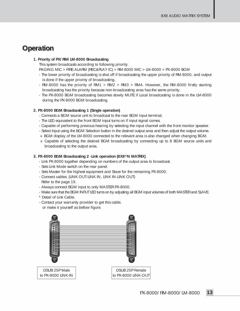
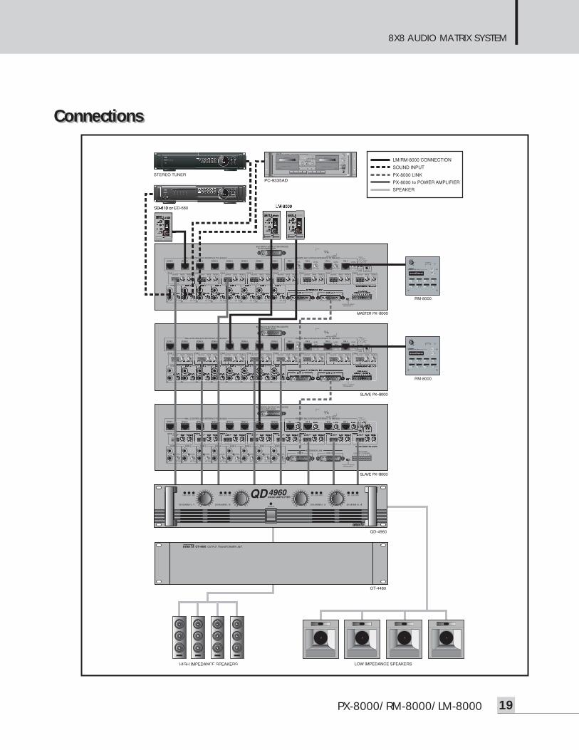
3. PX-8000 BGM Broadcasting 2 -Link operation (8X8^N MATRIX)- Link PX-8000 together depending on numbers of the output area to broadcast.- Sets Link Mode switch on the rear panel.- Sets Master for the highest equipment and Slave for the remaining PX-8000.- Connect cables. (LINK OUT-LINK IN, LINK IN-LINK OUT)- Refer to the page 19.- Always connect BGM input to only MASTER PX-8000.- Make sure that the BGM INPUT LED turns on by adjusting all BGM input volumes of both MASTER and SLAVE.* Detail of Link Cable. - Contact your warranty provider to get this cable.
or make it yourself as bellow figure.
1
1
14
1413
13
25
25
DSUB 25P Maleto PX-8000 LINK-IN
DSUB 25P Femaleto PX-8000 LINK-OUT
8X8 AUDIO MATRIX SYSTEM
14 PX-8000/RM-8000/LM-8000
4. PX-8000 BGM Broadcasting 3 - Same BGM Broadcasting in all output zonesTo select BGM using the BGM selection button in each output area is allowed but you can change BGM
of all the areas at a time. Even in link, changing all BGM in the MASTER PX-8000 is also applied to allthe Slave PX-8000 connected.
- Press the BGM ALL button on the front once.- "ALL 1" is displayed on the BGM Selection Display on all the front PX-8000.- Numbers increase whenever pressing the BGM ALL button.- Press the ENTER button if a BGM to broadcast is determined.- The selected BGM is broadcast to all the output terminals while the BGM Selection Display of all the
output area is changed to selected number.- Returns to the previous status if pressing the ESC button.
BGM of all the PX-8000 linked is changed if pressing BGM ALL from the Master PX-8000 for link. Only BGM of the SLAVE’s output area is changed if pressing BGM ALL from the Slave PX-8000 for link.
5. PX-8000 PAGING MIC Broadcasting 1 (Single operation)- MIC Connection1) After connecting MIC to the front MIC input terminal, adjust volume and tone.2) If using a condenser MIC, set the PHANTOM POWER switch on the rear side of the unit to ON and
MIC input must be applied with a balanced plug.3) If using a unbalanced dynamic MIC, sound level and quality can be degraded. It is recommended to
use balanced dynamic MIC.- Selection of Broadcasting Area1) Check the turning-on status by pressing the Paging Area Selection button equivalent to the area to
broadcast. 2) Press the PAGING ALL button for broadcasting to all areas. The All Area Selection button toggles.
- Chime Setup1) SWITCH1 ON : Chime increased by 2 tones for starting broadcast is emitted when pressing the
TALK button.2) SWITCH2 ON : Chime increased by 4 tones for starting broadcast is emitted when pressing the
TALK button. 3) SWITCH3 ON : Chime decreased by 4 tones for ending broadcast is emitted when pressing the
TALK button. 4) SWITCH1, 2 ON : Same as for SWITCH1 ON.
- Broadcasting1) After selection of broadcasting area, press TALK button for broadcasting.2) Chime broadcasting is emitted depending on Chime Mode Switch.3) "P" is displayed on the display window of PX-8000 and LM-8000 of the relevant area.4) Press TALK button again when ending broadcasting.5) Ending Chime is emitted depending on Chime Mode Switch 3.6) The Area Selection button turns off and the display window of PX-8000 and LM-8000 is changed to
the previous BGM display status.
8X8 AUDIO MATRIX SYSTEM
15PX-8000/RM-8000/LM-8000
6. PX-8000 PAGING MIC Broadcasting 2 (Link operation)- MIC Connection
1) Connect a MIC to the MIC input jack of MASTER PX-8000 if using PX-8000 together.2) The MIC Connection connected to the SLAVE unit is automatically shut off.
- Selection of Broadcasting Area1) All Area Selection (MASTER)
All areas are selected if pressing the PAGING ALL button of MASTER PX-8000.2) Individual Area Selection
A. Select the desired broadcasting area of the Master and Slave.- Chime Setup 1) Chime operates depending on setting of MASTER PX-8000
- Broadcasting1) All area broadcasting with MASTER PAGING ALL button.
a. Select all zones including MASTER&SLAVE using PAGING ALL button of the MASTER PX-8000.b. Also use TALK button of the MASTER.c. Starting chime operates according to the MASTER.d. Deliver your voice to the phone.e. Press TALK to finish the broadcasting. f. Ending chime operates according the the MASTER.
2) MASTER/SLAVE Zone-selective broadcastinga. First, select areas and press TALK button of each SLAVE PX-8000.b. select areas and press TALK button of the MASTER PX-8000.c. Starting chime is delivered to both MASTER and SLAVE areas according to the chime mode switch
of the MASTER PX-8000.d. Announce the messages to the microphone.e. Press TALK button of the MASTER, and ending chime will be heard.f. Press TALK button of all the SLAVEs.
3) Only MASTER Zone broadcastinga. Select zones of the MASTER.
Do not press PAGING ALL button, or all the area including SLAVEs will be selected.b. Press TALK button of the MASTER to broadcast to only MASTER areas. c. Starting chime operates according to the MASTER.d. Deliver your voice to the phone.e. Press TALK to finish the broadcasting. f. Ending chime operates according the the MASTER.
4) SLAVE Zone broadcastinga. Select areas and press TALK button of each SLAVE. b. Announce and terminate the broadcast pressing TALK button of each SLAVE.c. Chime function is not available when broadcasting except for MASTER PX-8000.
8X8 AUDIO MATRIX SYSTEM
16 PX-8000/RM-8000/LM-8000
7. PX-8000 Built-in IC Recording and PlaySince this unit has the built-in digital recording IC, the user can record the desired voice. Recording canbe done up to 30sec and recorded contents are broadcast to the relevant area in link with the fire alarmpoint on the rear side of unit. To change recording contents, perform recording again.- MIC Connection1) Adjust volume and tone after connecting MIC to the Paging MIC input on the front side.2) Available MIC is same as for broadcasting using a Paging MIC.
- Recording standby1) A "-record-" is displayed on the front display window if pressing the REC button once, and On
Recording Standby is displayed. 2) Press the ESC button to cancel recording.
- Recording1) Press the REC button to record for a second if ready for recording is completed. 2) "In Recording" is displayed while "-" mark on the edge rotates clockwise.3) If recording is completed, press the REC button again to end.4) Contents passing 30sec are not recorded.
- Records Check1) If shorting GND and the PIN number equivalent to each output area of the FIRE CONTACT
CLOSURE’ terminal on the rear side of the unit, previously recorded contents are broadcast to therelevant output zone.
2) "F" is displayed on the display window of the PX-8000 and LM-8000 during play.Recorded contents are unlimitedly played while the contact is connected, and play is terminated if the
contact is released.If configuring PX-8000 as link system, it is recommended to individually record by setting respectivePX-8000 to Master Mode.If the contact operates during record course, only contents before the contact are recorded. Thusrecord again after the contact is terminated.
8. LM-8000 Connection- Connect to the LM-8000 connection terminal on the rear side of PX-8000 by using CATEGORY5 (UTP)
material.- The connection jack numbers of the connected PX-8000 show output area and ensure connection of up
to 300M.- Connection of 8 sets of LM-8000 to a PX-8000 is allowed.- Immediate use is allowed by automatically recognizing LM-8000 without need of separate ID setting.- If powering on, 0, 1, 2, 3, 4, 5, 6, 7, 8, A, B, C, D, E and F are orderly displayed on the BGM display
window of LM-8000 and the BGM number is displayed for the relevant area.- You can select BGM or adjust BGM output volume of BGM output volume using a LM-8000 if a DOT (.)
is displayed on the LM-8000 BGM Display Window.- You may endow with or release the control right of LM-8000 using the WALL CTRL button on the front
side on the PX-8000. If the right is endowed to LM-8000, the button of PX-8000 lights and if DOT(.) isdisplayed on the LM-8000 BGM Display Window.
- Check connection status and the unit if "E" continues to flash on the display window. Turn the encoder volume clockwise until checking is done that volume is changed since volume is setto minimum for the initial use.
8X8 AUDIO MATRIX SYSTEM
17PX-8000/RM-8000/LM-8000
9. Change of Main BGM and adjustment of volume in output area using LM-8000- Endow with the control right of LM-8000 by pressing the WALL CTRL button of PX-8000.- Check that the BGM number is changed, by operating the BGM Selection Button of LM-8000.- Same BGM number is displayed on the front BGM Display Window of PX-8000 and LM-8000 - Adjust local output volume using a volume adjustment encoder.
The volume adjustment encoder of LM-8000 and the slide volume (FADER) on the front side of PX-8000 unit control the BGM broadcasting volume of the output area. A paging MIC broadcastingand the local output volume of RM-8000 are not controlled with the encoder and the slide volume.
10. Independent Local BGM and MIC Broadcasting using LM-8000Independent local broadcasting is possible if using LM-8000. You can perform the desired MICbroadcasting or listen to BGM music in respective area other than the Main BGM connected to PX-8000.LOCAL BGM&MIC of LM-8000 has higher priority than Main BGM of PX-8000 and thus main BGMautomatically becomes MUTE during the independent local broadcasting of LM-8000.- Connect the desired MIC or sound source unit to MIC or LINE input.- Adjust volume by using the respective volume to adjust input sound.- Immediate broadcasting is allowed and the local output volume is adjusted by using encoder of LM-
8000 or a slide volume of PX-8000.- Main BGM on the BGM Display Window becomes MUTE when performing independent LM-8000
broadcasting. If there is no local broadcasting, Main BGM is broadcast while MUTE is released.A condenser MIC cannot be used for the LM-8000 LOCAL MIC broadcasting.Display status of the BGM Display Window for LM-8000 is as follow:For PX-8000 Paging broadcasting PFor PX-8000 FIRE ALARM FFor RM-8000 broadcasting R
11. RM-8000 Connection- Connect to the RM-8000 connection hole on the rear side of PX-8000 using a CAT5 (UTP) wiring
material. Same as connection method of LM-8000.- Immediate broadcasting is allowed without separate ID setting.- 4 sets of RM-8000 can be connected. - If powering on, buttons sequentially turn on/off simultaneously with power LED turned on.- Flashing of buttons mean defect of the unit or connection status, thus check connection status and the unit.
12. RM-8000 MIC Broadcasting- Connect a MIC to the MIC input jack. Both dynamic MIC and condenser MIC can be used.- Set the Chime Mode Switch on the rear side of RM-8000.A. SWITCH1 ON : Chime increased by 2 tones for starting broadcast is emitted when pressing the
TALK button.B. SWITCH2 ON : Chime increased by 4 tones for starting broadcast is emitted when pressing the
TALK button. C. SWITCH3 ON : Chime decreased by 4 tones for ending broadcast is emitted when releasing the
TALK button. D. SWITCH1, 2 ON : Same as for SWITCH1 ON.
8X8 AUDIO MATRIX SYSTEM
18 PX-8000/RM-8000/LM-8000
- The button turns on if pressing the relevant button of the area to broadcast. All regions of the PX-8000,where the relevant RM-8000 is connected, are selected if pressing the ALL button.
- MIC broadcasting is done with the TALK button pressed. In this case, perform broadcasting afterchecking start of Chime broadcasting using a built-in monitor speaker.
- Adjust MIC input volume of PX-8000 and input volume of PX-8000 while listening to broadcastingvolume or checking the level meter.
- "R" is displayed on the BGM display window of PX-8000 and LM-8000 of the broadcasting area.- Release the TALK button pressed to end broadcasting. TALK button is on PTT method.- Check ending of Chime broadcasting using a built-in monitor speaker.
13. RM-8000 Priority Broadcasting- Broadcasting of any RM-8000 is allowed in the non-broadcasting area.- Zone being broadcasting area has priority with the order of RM1 > RM2 > RM3 > RM4.- If the relevant area button turns off when pressing the broadcasting area button and then pressing
TALK button, other RM is already broadcast in the same area, and the user can know which RM-8000is broadcasting with the [IN-USE LED] turned on.
- If the area button selected during broadcasting turns off and the other [IN-USE LED] turns on, the otherRM-8000 with a high priority is broadcasting in the same area.
14. RM-8000 Broadcasting in linked systemIf using the PX-8000 together, MIC broadcasting of the RM-8000 is not allowed to the output area of the otherPX-8000. Broadcasting is allowed to only the output area of PX-8000 where the RM-8000 is connected.
8X8 AUDIO MATRIX SYSTEM
19PX-8000/RM-8000/LM-8000
ConnectionsConnections
8X8 AUDIO MATRIX SYSTEM
20 PX-8000/RM-8000/LM-8000
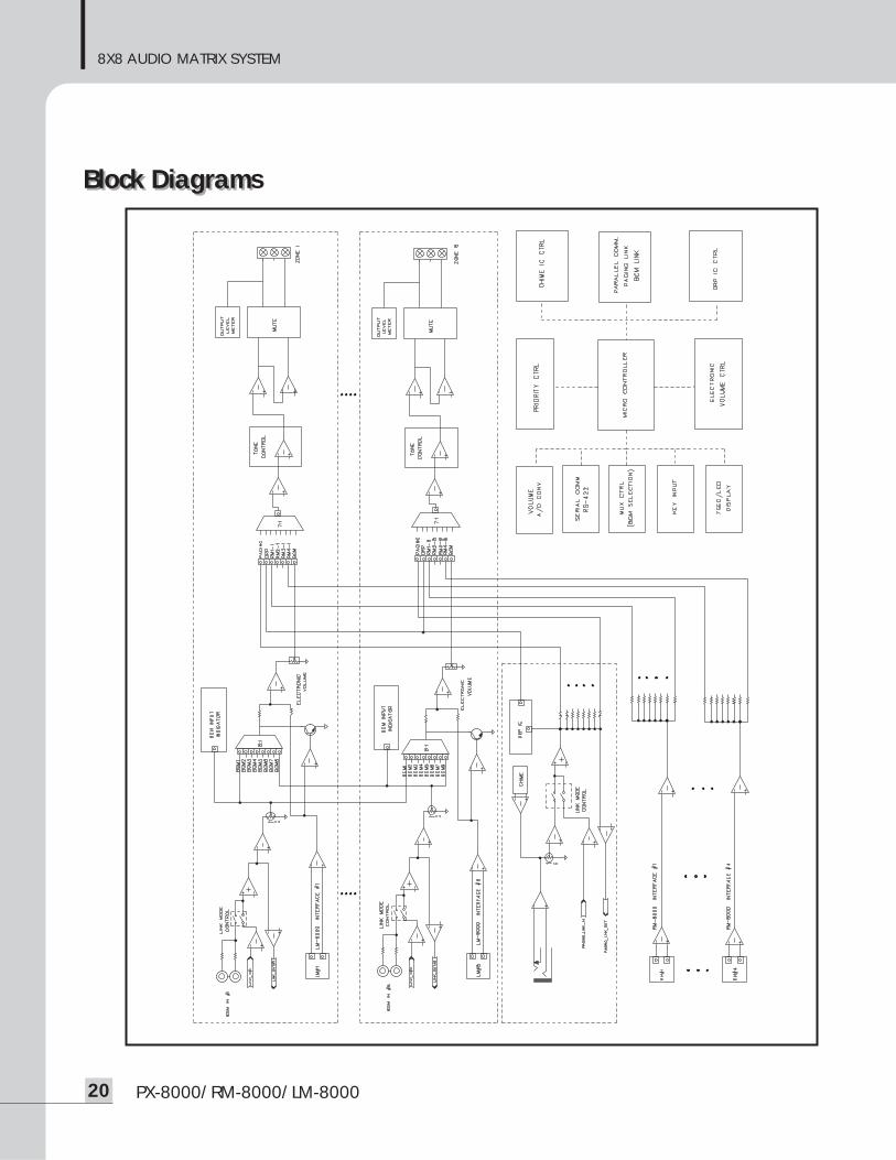
Block DiagramBlock Diagrams
8X8 AUDIO MATRIX SYSTEM
21PX-8000/RM-8000/LM-8000
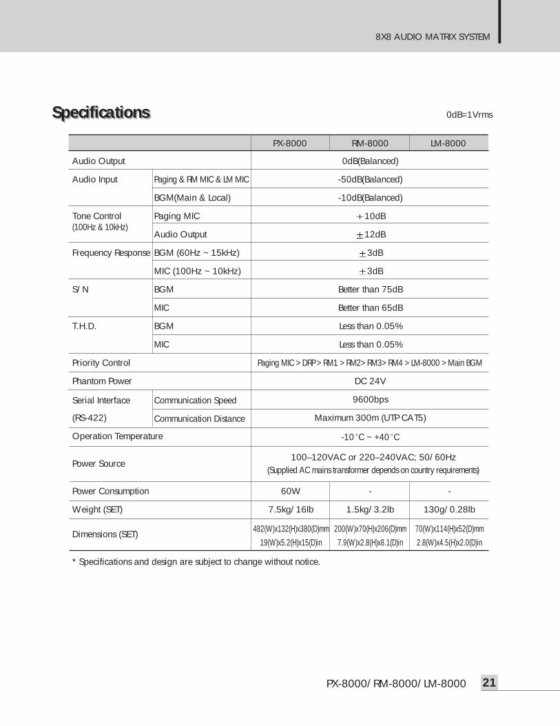
SpecificationsSpecifications ................................................................................................................0dB=1Vrms
PX-8000 RM-8000 LM-8000
Audio Output 0dB(Balanced)
Audio Input Paging & RM MIC & LM MIC -50dB(Balanced)
BGM(Main & Local) -10dB(Balanced)
Tone Control Paging MIC 10dB(100Hz & 10kHz)
Audio Output 12dB
Frequency Response BGM (60Hz ~ 15kHz) 3dB
MIC (100Hz ~ 10kHz) 3dB
S/N BGM Better than 75dB
MIC Better than 65dB
T.H.D. BGM Less than 0.05%
MIC Less than 0.05%
Priority Control Paging MIC > DRP > RM1 > RM2> RM3> RM4 > LM-8000 > Main BGM
Phantom Power DC 24V
Serial Interface Communication Speed 9600bps
(RS-422) Communication Distance Maximum 300m (UTP CAT5)
Operation Temperature -10 C ~ +40 C
Power Source100–120VAC or 220–240VAC; 50/60Hz
(Supplied AC mains transformer depends on country requirements)
Power Consumption 60W - -
Weight (SET) 7.5kg/16lb 1.5kg/3.2lb 130g/0.28lb
Dimensions (SET) 482(W)x132(H)x380(D)mm 200(W)x70(H)x206(D)mm 70(W)x114(H)x52(D)mm19(W)x5.2(H)x15(D)in 7.9(W)x2.8(H)x8.1(D)in 2.8(W)x4.5(H)x2.0(D)in
* Specifications and design are subject to change without notice.
8X8 AUDIO MATRIX SYSTEM
22 PX-8000/RM-8000/LM-8000
ServiceService
ProceduresEnsure the problem is not related to operator error, or external system devices, Once it is certain that theproblem is related to the product contact your warranty provider as described in the warranty section of thismanual.
SchematicA Schematic is available by contacting your warranty provider.
Parts ListA Parts List is available by contacting your warranty provider.
Variations and OptionsVariations and Options
VariationsVariations of this product exist to reflect the variations in AC power requirements throughout the world. Productsupplied through local sources are compatible with local AC power requirements.
Options No optional items are available for this product.
WarrantyWarranty
Warranty terms and conditions vary by country and may not be the same for all products. Terms and conditionsof warranty for a given product may be determined first by locating the appropriate country which the productwas purchased in, then by locating the product type.
To obtain specific warranty information and available service locations contact Inter-M directly or theauthorized Inter-M Distributor for your specific country or region.

NOTE

NOTE

NOTE
MADE IN KOREAAugust 2007 9000004220
Inter-M, Ltd. (Korea) began operations in 1983.
Since then, Inter-M has grown to become one of the largest manufacturers of professional audio and commercial sound electronics equipment in the world.
Inter-M has gained worldwide recognition for its own branded products, as well as private label manufacturing of electronics sold under other names (OEM).
The company is no longer just a Korean company, but rather a global company that is truly international in scope, with factories and offices in Korea and China, and sales and marketing operations located in Japan, Europe, and the U.S.A.
With more than 850 employees around the globe,Inter-M is well-poised for further growth and expansion.
Inter-M Americas, INC. 13875 ARTESIA BLVD. CERRITOS, CA 90703 USATEL : +1-562-921-0313, FAX : +1-562-921-0370Home Page : http://www.inter-m.net, E-mail : [email protected]
Inter-M CorporationSEOUL OFFICE:653-5 BANGHAK-DONG, DOBONG-KU, SEOUL, KOREA TEL : +82-2-2289-8140~8, FAX : +82-2-2289-8149Home Page : http://www.inter-m.com, E-mail : [email protected]