operation & maintenance manual · operation & maintenance manual table of contents...
TRANSCRIPT
Operation & Maintenance Manual
Table of Contents Introduction Section 1.0 Plant Routine Inspection and Service Instructions Section 2.0 Operating Instructions Section 3.0 Teflon Diffuser Inspection Section 4.0 Plant Troubleshooting Guide Section 5.0 Hydro-Action® AP-Series Plant Specifications Section 6.0 Process Description Section 7.0 Safety Appendix 1: OPS Explanation Guide Appendix 2: Hydro-Action® AP Series Pump Selection Appendix 3: Technical Manual for Timers Appendix 4: Electrical Controls Schematics Appendix 5: Drawings Appendix 6: Misc. Forms & Documents
Introduction The AP Series Aerobic Treatment Units (ATUs) are now available through Hydro-Action®. Please read this introduction before reviewing this manual. Earth’s environment has purified water through natural processes since the beginning of time. Only recently, beginning in the Twentieth Century, has man developed a system to accelerate the processes that Mother Nature uses. Hydro-Action® AP Series ATUs are just such systems. In 1916, the City of Houston, Texas, was the first to use the activated sludge wastewater treatment process as an accepted, full-scale system process to purify domestic wastewater. Since that time, the United States and many other nations have utilized this process and variations to properly treat sewage. Federal Law 92-500 supports our nation’s commitment to provide secondary treatment for all domestic wastewater. This commitment is presently being extended to on-site sewage treatment facilities. Hydro-Action® has been a visible part of this effort since 1989. We have manufactured numerous products to provide individuals with a means of proper, effective, efficient, and affordable on-site wastewater treatment. Our professional commitment to market needs and customer service have enabled us to reach our goal of providing effective products that assure a safe, reusable effluent. We are helping Mother Nature protect our environment and our most valuable natural resource: water. Hydro-Action® AP Series Aerobic Treatment Units are among the most advanced on-site products available today. They are state-of-the-art extended aeration, activated sludge wastewater treatment facilities. The improvements in these units make them not only extremely efficient operational units but also the most easily maintainable system in the industry.
By following the instructions in this manual, you will be providing yourself with the best on-site wastewater treatment and service. We invite you to share in our pride of the AP Series Treatment Units. This manual includes information on the AP-500, LPA 500, AP-600, AP-750, AP-1000G & AP-1500G wastewater treatment plants. These units may be installed with either a platform mounted OPS® (operations/control center) or a Remotely Located OPS®. Installation needs vary, so your on-site wastewater system may contain some of the following auxiliary components along with the treatment plant: • Pretreatment tank • Pump/holding tank • Alarm systems • Equipment for chosen effluent disposal method (drip irrigation, spray irrigation, gravel-filled drain field, pressure dosing, etc.) • Chlorinator / UV Disinfection Unit The certified Hydro-Action® dealer or installer of your Hydro-Action® AP Series wastewater treatment plant is responsible for completing and submitting to us the Installation Warranty Information to properly activate your Hydro-Action® Product Warranty. We are eager to assist you with any questions or problems. Please contact Hydro-Action® at 800.370.3749 to request assistance from our Customer Service or Engineering Departments.

SECTION 1.0: Plant Routine Inspection and Service Instructions 1.1: Each site should be inspected and serviced by following these simple instructions. As each site may have differences due to selected disposal options, inspect each site facility to determine which options are present then proceed with the following instructions. 1.1.1: Upon arrival at the site, remove the tamper-resistant screws from the Hydro-Action® plant access cover and the Platform Mounted OPS® or Remotely Located OPS® enclosure. Then remove the access cover and enclosure. Set the security screws and covers in a protected place for later reassembly. 1.1.2: Collect an activated sludge sample from the aeration compartment. The sample size should be approximately one quart. Collect the sample as soon as possible; you can perform other work while the solids are settling and thereby reduce your inspection time at the site. Use this sample to run the sludge volume test (15 minutes settable solids ml/L test). To perform this test a one-liter graduated cylinder or any tall, straight-sided, clear glass container, about one-quart in capacity, will be needed. Divide the container into 10 equal parts using a waterproof marker, thus signifying 0 to 100%. a. Immediately after sample is collected, fill graduated container to 100% mark. b. Allow sample to stand for 15 minutes. c. Measure sludge volume by locating interface between clarified effluent and settled sludge on graduations. Interface should be between the 20% and 60% marks, indicating a well-functioning plant. Values less than 20% or greater than 60% indicate there is a problem. Sludge layer should be chocolate in color and full of very small particles resembling small pieces of sponge. Refer to the Hydro-Action®
Plant Condition Chart, section 4.12. 1.1.3: As turbulence in the aeration compartment caused by the rising fine air bubbles can be seen, observe any significant changes in mixing and aeration characteristics.
If insufficient mixing or poor aeration is observed, refer to Section 1.1.4a. All Diffuser assemblies should appear to have equal turbulence. This is an indication of proper diffuser assembly and diffuser operation. 1.1.4: Proper aeration in the Hydro-Action®
AP-Series is maintained by performing the following maintenance operations: a. Clean or replace the air pump inlet filter during routine inspections; inspect the aeration compartment surface through the access port to determine the amount of turbulence caused by air coming from each diffuser assembly. All Diffuser assemblies should appear to have equal turbulence. This is an indication of proper diffuser assembly and diffuser operation. b. Locate the Schrader air pressure valve on the PVC air pump discharge line. Unscrew the protective cap and connect the quick chuck pressure gauge. Read and record the pressure. If the pressure equals or exceeds 3.5 psig, a high pressure condition exists. After pressure reading is complete, remove the quick-chuck pressure gauge and replace the protective cap on the Schrader air pressure valve. 1.1.5: To inspect, clean, or replace air diffuser assemblies, refer to Section 3.0. 1.1.6: Using a clean, clear sample bottle catch an effluent sample from the pump tank or other discharge point. Effluent should have a non-offensive odor and be clear in color. If results differ from these refer to section 4.0, Plant Troubleshooting Guide. 1.1.7: Check the surface of the clarification compartment for floating solid or scum buildup. If build-up is found, remove it using a small net with very fine mesh and dispose of off-site according to all federal, state, and local regulations. (Material may be returned to system upstream of plant through cleanout.) Using a garden hose, spray a high-pressure stream of water into clarifier, breaking up any remaining floating solids. Clean any over spray from the general area.

1.1.8: Activate liquid level alarm by raising and lowering float in clarifier to test both audible and visible alarms. Disrupt the air pressure by disconnecting the air pressure tubing from the electrical enclosure inside OPS® to test air pressure alarms. If any problem is experienced with alarm functions, make necessary adjustments, corrections, and/or repairs. If optional remote alarm has been installed, be sure that its audible and visual alarms are also working correctly. 1.1.9: The switch indicated “normal/silence” on OPS® models 50-11, 20, -30 & -32 is used to test the alarms, silence an alarm condition, or is left in the normal on position. The normal position of the mode is for normal operation of the plant and silence is a mode that will disrupt both the audible and visual alarm. Move the switch to the left and hold to test the alarms. The test switch will reset itself automatically. These alarms should always be tested before leaving the site to assure they are operational. 1.1.10: If optional effluent pump is included on system, activate pump float switch to assure effluent pump is operational; set and adjust timers as required (if installed). 1.1.11: Reinstall Hydro-Action® access covers being sure to install and tighten tamper-resistant screws to prevent unauthorized plant entry. 1.2: Each site visit requires an investigation of the solids inventory within the wastewater treatment plant and a determination of when excess solids need to be removed from the system. Follow these procedures in evaluating solids inventory:
a. Hydro-Action® plant inspection and service should be performed a minimum of every six (6) months. This inspection and service includes performing a sludge volume test, which is an indicator of plant performance. (Refer to section 4.0, Plant Troubleshooting Guide.)
b. When sludge volume in plant aeration
compartment reaches 60% to 80% it is time to pump the plant and pretreatment tank (if included). This is usually necessary every two (2) to six (6) years.
1.3: Follow these procedures to pump the sludge solids from the treatment tanks. A qualified service technician should oversee the work performed. 1.3.1: Remove the plant access cover. 1.3.2: Refer to installation worksheet to determine which tanks and auxiliary equipment are included on this particular installation (i.e., pretreatment tank, surge tank, pump tank, access covers of different units). Remove pump tank access cover (if included). If necessary, use a shovel to dig down and expose the pretreatment tank access covers and remove them. Remove the clean-out adapter plug from the outlet tee fitting. The tanks are now ready to be pumped. 1.3.3: The suction hose should be positioned to be very near the bottom of the tanks. Care should be taken not to damage internal components. The plant and other tanks should be washed and cleaned while they are being pumped. The waste from the tanks should be disposed of in compliance with local, state, and federal laws. 1.3.4: It is important that care is taken when pumping plant and any other tank to assure that hydraulic displacement of tanks (floating of tanks) does not occur. Tank flotation may occur whenever water and solids are removed from the tank when high groundwater conditions exist. Any source of water in the soil around the plant installation could cause the tank to float. Water sources may include rainfall, springs, creeks, bayous, rivers, lakes, and coastal areas. Proper precautions are therefore required to prevent tank flotation due to hydraulic displacement. These precautions include, but are not limited to, the following: • Plant location — choose a site that will minimize possible groundwater saturation. Consider seasonal water table and soil conditions in the area of installation. Do not locate the plant in a low spot in the ground where water tends to pool or at the edge of any natural body of water. If such a location cannot be avoided, call Hydro-Action® for technical advice.
• Whenever a tank is pumped, do not remove more than one-half of the capacity of the tank. It is recommended that you pump the tank during dry seasons only. However, if tank must be pumped during the wet season, watch for upward movement of the tank while pumping is being done. If upward movement is detected during pump, immediately stop pumping water out of the tank and refill the tank to stop flotation. Each site must be evaluated on a case-by-case basis to determine the best time to remove water from the tank and prevent flotation. 1.3.5: Replace the pre-treat, plant access, and pump tank access cover (if included), being sure to reinstall and tighten the Hydro-Action®
tamper-resistant screws to prevent plant entry of unauthorized personnel. Note: Plant and other tanks should be filled with water before leaving site. 1.4: Normal maintenance on the Hydro-Action® AP Series plant will include: Every Six (6) Months: a. Maintaining aeration system and air diffusers. b. Maintaining air pump. c. Removing scum from clarifier. d. Inspecting and testing plant alarms. Every Two (2) to Six (6) Years: e. Pumping excess sludge from plant. Note 1: The owner has been informed that replacement parts can be obtained from a Hydro-Action® Certified Dealer. Note 2: Pumping the plant is usually necessary every two (2) to six (6) years; however, there is no set time because loadings vary from household to household. Access to the plant is accomplished through the access opening, which is at surface grade. When a Hydro-Action® plant is being pumped, a qualified service technician should oversee the job. The waste from the plant must be disposed of in compliance with all federal, state, and local laws.
SECTION 2.0: Operating Instructions 2.1: The Hydro-Action® AP Series Plant has been designed and built to provide efficient, and reliable service. However, as with any individual wastewater treatment plant, routine periodic service is required. When proper preventive maintenance is performed, the Hydro-Action®
plant will operate at designed performance levels to give years of satisfactory treatment of domestic wastewater. 2.2: Local Hydro-Action® Dealers are required to perform all routine inspections for the first two (2) years from the original date of installation. At the time of inspection the plant will be checked for proper operation. If a problem exists, service will be performed at no charge to the owner, unless the required maintenance is not warranty related. At the end of the two (2) year initial service period, the local dealer will make available a continuing service policy. This extended service is available for a nominal fee. 2.3: The Hydro-Action® OPS® is equipped with an alarm beacon and an audible horn alarm. Also on the OPS® should be the name, address, and telephone number of the local servicing dealer. An optional remote alarm with audible and visual alarms may also be present. Should either alarm come on, the owner is instructed to call the local dealer. After a power failure, if an alarm remains on for more than 30 minutes the owner is instructed to call the local dealer immediately. To silence audible alarm while waiting for service technician to arrive, owner should locate the switch on outside face of the OPS® enclosure labeled “normal/silence” and push it to the “silence” (right) position. Visual alarm beacon will remain illuminated. 2.4: The Hydro-Action® AP-Series Plant will handle all domestic wastewater. The term domestic wastewater refers to rapidly biodegradable material. To keep maintenance at a minimum and to prevent the plant from malfunctioning, the following guidelines need to be followed:
• Since aerobic bacteria are responsible for treating the wastewater, inorganic or non-rapidly biodegradable materials should not be put into the plant. Examples of improper items are: plastic products, rubber products, sanitary napkins or tampons, washcloths, cigarette butts, melon seeds, coffee grounds, egg shells, matches, some food items such as corn husks, grape vines, etc. • Do not introduce cooking grease or large amounts of oil into plant; instead pour it into a container and dispose of it properly. • To minimize pump-out frequency, limit use of garbage disposals. • Lint from lint catchers, hair, etc., should be disposed of in the trash and not washed down the drain. • Water softener backwash should not be routed through the system. Another source of disposal should be used. • Diapers can be rinsed out in the toilet; however, do not flush cloth or disposable diapers down the toilet. • Large amounts of harsh chemicals, high foaming detergents, disinfectants or any substance that kills bacteria must not be discharged into the plant. • The plant will not perform to its fullest capabilities if volumetric overload is allowed to occur. This occurs whenever excessive water, above the designed flow rate, is allowed into the plant. Excessive water use or leaking plumbing fixtures may cause this condition. Hydro-Action® Dealers & Certified Technicians are asked to inform homeowner of these guidelines. Too often a malfunctioning treatment unit is due to abuse that can be avoided with simple education. 2.5: Other than for the mechanical and structural working of the plant itself, Hydro-Action® is not responsible for the in-field operation of a plant. The proper operation of this or any other individual wastewater plant depends upon proper organic and hydraulic loading of the plant. We cannot control the
loading and thereby control the amount of harmful substances that may be discharged into the plant. Only the users of a plant can control what enters the unit. Therefore, we provide a comprehensive owner’s manual that outlines substances that should be kept out of the plant. 2.6: The Hydro-Action® AP-Series must be installed and maintained according to factory specifications. No modifications of equipment or design are allowed. Modification of the plant will void warranty and invalidate NSF certification of plant. 2.7: OPS® models 50-30 or 50-32 include a timer, which may need to be reset. The 50-30 is a 24-hour, and the 50-32 is a micro-dose timer. See the Technical Manual section of timers in Appendix 3. SECTION 3.0: Teflon Diffuser Inspection 3.1: With plant access cover removed, look through the plant access opening. Inspect system to insure even flow of diffused bubbles are coming from each diffuser. 3.2: Locate the Schrader air pressure valve on the PVC air pump discharge line. Unscrew the protective cap and connect the quick chuck pressure gauge. Read and record the pressure. If the pressure equals or exceeds 3.5 psig, a high pressure condition exists. Note: Whenever a high pressure condition exists in the Hydro-Action® diffuser airline assembly it is usually due to a blockage. This could be either inside the lines or bacterial growth on the diffusers themselves. 3.3: To remedy a high pressure condition first try to pressurize the airline with a high pressure air compressor. This will displace any bacterial growth on the diffusers themselves. 3.4: If the pressurizing of the lines does not improve the pressure condition then the diffusers may need to be replaced. Note 2: Diffuser assemblies are normally not replaced on the newer AP Series with the Teflon diffusers. Older models will need retro-fit.
SECTION 4.0: Plant Troubleshooting Guide 4.1: The Hydro-Action® AP Series plant has proven to be very effective and reliable in the treatment of domestic wastewater. The problems outlined here occur only in a very small percent of total installations. They can all be corrected and most can be prevented. 4.2: When the owner/user calls, ask him or her to describe the problem in detail and determine the plant age and service history from your records. This information is then used in preparation for the service call. 4.3: First perform a routine service call as described in section 1.0, Plant Routine Inspection and Service Instructions. 4.4: If routine servicing does not solve the problem, go through the steps listed below. 4.5: Verify model number of plant and OPS®
with those in records. If this is a new installation, you should verify that the plant and all its components were installed correctly and in accordance with manufacturers and regulatory agency requirements. See Hydro-Action® AP Series Installation Manual, available from Hydro-Action®. 4.5.1: Inspect plant to verify that the Hydro-Action® plant is installed properly and is not damaged. Plant should be level and internal components should be in proper place and correct working order. 4.5.2: Check to see that effluent disposal method is allowing for proper level to be maintained in plant. High level in plant can adversely affect performance. 4.6: After confirming that Hydro-Action® plant is installed properly and is not damaged, check the operational and maintenance conditions of the plant to determine if it is performing correctly. To do this run a sludge volume test as described in section 1.0. Compare your findings with the conditions given in the Hydro-Action®
Plant Condition Chart, section 4.12. Follow the recommended actions required to return the plant to its proper operating conditions.
4.7: The alarms supplied with this wastewater treatment plant provide the owner with a secure, reliable and economical means of notification for most malfunctions of the plant that would lead to producing an unsatisfactory effluent. These alarms include notification for problems of air pump failure, aeration piping malfunctions, and high water level. These alarms need to be inspected and tested during each plant operation and maintenance site visit. If an optional remote alarm has been installed, it should also be inspected and tested during each site visit. 4.8: To gain access to the electrical controls and air pump, remove the security screws holding the OPS® enclosure to the base. 4.9: The switch indicated “normal/silence” on all OPS® models is used to test the alarms, silence an alarm condition, or is left in the normal on position. The normal position of the mode is for normal operation of the plant and silence is a mode that will disrupt the audible alarm. Move the switch to the left and hold to test the alarm. You should see and hear the visible and audible alarms when this mode is selected. The OPS® switch will reset itself automatically. 4.10: If the audible and visual alarms on the outside face of the Hydro-Action® OPS®
enclosure are indicated the problem might be failure in power supply or air pump, or an electrical short in the line between electrical controls and air pump. See Appendix 2 & 5 for electrical schematics and pump manuals. 4.11: The AP-Series plant is equipped with a high-level float switch and alarm. If the system also includes a pump/holding tank to remove effluent, the Hydro-Action® electrical controls may include a second high-level alarm. If the owner reports high-level alarm light on, service technician should be sent to correct the problem. A malfunctioning water pump or level float or a plugged discharge could cause the high level conditions. A malfunctioning high-level sensor float could give a false high-level alarm. This problem left uncorrected will lead to system failure and improper wastewater treatment and therefore requires immediate attention.
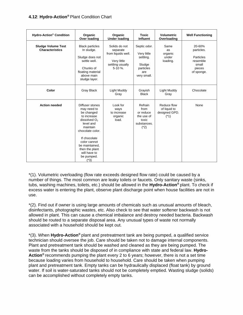
4.12: Hydro-Action® Plant Condition Chart
Hydro-Action® Condition
Organic
Over loading
Organic
Under loading
Toxic
Influent
Volumetric
Overloading
Well Functioning
Sludge Volume Test
Characteristics
Black particles
In sludge.
Sludge does not settle well.
Chunks of
floating material above main sludge layer.
Solids do not
separate from liquids well.
Very little
settling usually 5-10 %.
Septic odor.
Very little settling.
Sludge
particles are
very small.
Same
as organic under
loading.
20-60%
particles.
Particles resemble
small pieces
of sponge.
Color
Gray Black
Light Muddy
Gray
Grayish Black
Light Muddy
Gray
Chocolate
Action needed
Diffuser stones
may need to be changed to increase
dissolved O2 level and maintain
chocolate color.
If chocolate color cannot
be maintained, then the plant
will have to be pumped.
(*3)
Look for
ways to increase
organic load.
Refrain
from or reduce the use of
toxic substances.
(*2)
Reduce flow of liquid to
designed GPD. (*1)
None
*(1). Volumetric overloading (flow rate exceeds designed flow rate) could be caused by a number of things. The most common are leaky toilets or faucets. Only sanitary waste (sinks, tubs, washing machines, toilets, etc.) should be allowed in the Hydro-Action® plant. To check if excess water is entering the plant, observe plant discharge point when house facilities are not in use. *(2). Find out if owner is using large amounts of chemicals such as unusual amounts of bleach, disinfectants, photographic wastes, etc. Also check to see that water softener backwash is not allowed in plant. This can cause a chemical imbalance and destroy needed bacteria. Backwash should be routed to a separate disposal area. Any unusual types of waste not normally associated with a household should be kept out. *(3). When Hydro-Action® plant and pretreatment tank are being pumped, a qualified service technician should oversee the job. Care should be taken not to damage internal components. Plant and pretreatment tank should be washed and cleaned as they are being pumped. The waste from the tanks should be disposed of in compliance with state and federal law. Hydro-Action® recommends pumping the plant every 2 to 6 years; however, there is not a set time because loading varies from household to household. Care should be taken when pumping plant and pretreatment tank. Empty tanks can be hydraulically displaced (float tank) by ground water. If soil is water-saturated tanks should not be completely emptied. Wasting sludge (solids) can be accomplished without completely empty tanks.

SECTION 5.0 Hydro-Action® AP Series Plant Specifications.
Plant Capacities
Model AP-500 LPA-500 AP-600 AP-750
AP-1000
AP-1500
Design Flow (Gallons/Day) 500 500 600 750 1000 1500
CBOD5 (Pounds/Day) 1.25 1.25 1.50 1.88 2.50 3.75
CBOD5 (mg/l) 290 290 290 290 290 290 TSS (mg/l) 360 360 360 360 360 360
Hydraulic Capacity (Gallons) Aeration Compartment 663 663 800 1002 1280 1895 Clarifier Compartment 173 173 219 273 352 518 Total Hydraulic Capacity 836 836 1019 1275 1632 2413
Hydraulic Retention Time (Hours) Aeration Compartment 32 32 31 29 29 25 Clarifier Compartment 8 8 9 9 8 8 Total Retention Time 40 40 40 38 37 33
Tank Dimensions Diameter (in) 66 72 66 72 66 88 Height to Water Line (in) 64 46 64 64 70 82 Height with OPS Installed (in) 103.5 88 103.5 103.5 109 118
Compressor Usage Rotary Compressor 1/4 HP 1/4 HP 1/4 HP 1/4 HP 3/4 HP 3/4 HP
Voltage (VAC) 115 115 115 115 115/120 115/120Current (Amps) 3.9 3.9 3.9 3.9 7.8/3.9 7.8/3.9
Power (Watts) 120 120 120 120 120/560 120/560Frequency (Hertz) 60 60 60 60 50 50
Flow (CFM) 4.3 4.3 4.3 4.3 8.2 8.2 Max Pressure (Psi) 5.0 5.0 5.0 5.0 7.0 7.0
Linear Compressor HP80 HP80 HP100 HP120 HP150 HP200 Voltage (VAC) 120 120 120 120 120 120
Current (Amps) 0.059 0.59 1.55 2.1 2.1 1.75 Power (Watts) 71 71 186 252 252 210
Frequency (Hertz) 50 50 60 60 60 50 Flow (CFM) 2.9 2.9 4.5 4.5 4.5 8.2
Max Pressure (Psi) 5.0 5.0 5.0 5.0 7.0 7.0
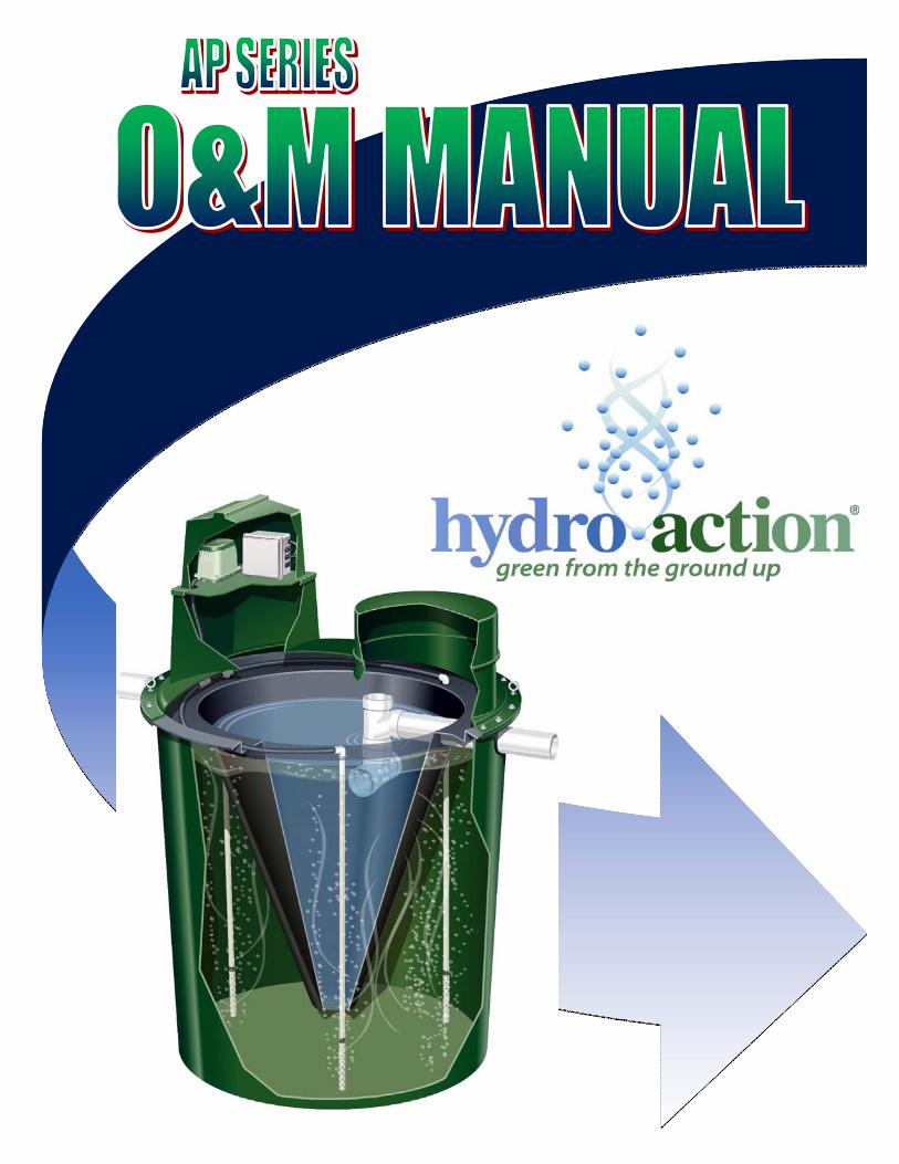
SECTION 6.0: Process Description 6.1: The Hydro-Action® AP Series individual wastewater treatment plant is a self-contained, extended aeration, aerobic treatment facility utilizing the activated sludge process. The plant consists of a cylindrically shaped aeration tank with an offset service access, a unique cone shaped clarification compartment and an outlet tee-assembly. Three fine-bubble Teflon diffuser assemblies and the Hydro-Action® air pump are combined to provide effective, efficient, and economical aeration. 6.2: Domestic wastewater enters the aeration compartment and is mixed thoroughly with the already present mixed liquor suspended solids (MLSS) activated sludge. The injection of air through the porous Teflon air diffusers placed near the bottom of the aeration chamber is responsible for this complete mixing. The fine-bubble diffusers and the vortex area between diffuser assemblies produce a high magnitude of air diffusion and therein provide ample mixing and a more than generous quantity of dissolved oxygen to maintain the aerobic environment even under extreme conditions. 6.3: Hydraulic displacement causes the mixed liquor to enter the clarification compartment and move upward toward the outlet tee-assembly. Due to the calm conditions in the clarifier, suspended solids settle to the bottom where they are remixed with the Mixed Liquor Suspended Solids (MLSS) for additional biological treatment. The remaining clarified effluent leaves the plant via the outlet tee assembly and discharge line. 6.4: The AP Series ATUs are operated by the OPS®. The OPS® integrates the electrical controls, visible and audible alarms and air pump in a protective polyethylene enclosure. The OPS® can be either platform mounted on the plant or remotely located. These features plus; the offset access, flexible air hose, and Teflon diffuser assemblies make the plant extremely reliable and easy to service. An optional visible and audible alarm may be added to remotely locate to an area of your choice.
6.5: The technology used in the Hydro-Action® plant allows it to produce excellent effluent quality, which thereby meets all ANSI\NSF International Standard 40 class I and the Environmental Protection Agency’s requirements of a secondary treatment process. NSF requires that a Class I plant shall be shown to meet EPA secondary treatment guidelines for CBOD5, TSS, and pH. The Hydro-Action® AP Series ATUs satisfy all these requirements. SECTION 7.0: Safety 7.1: Safety is an important issue in our business since we deal with one of the more potentially health hazardous materials known: raw sewage. Domestic wastewater carries in it members of a specialized group of life known as microorganisms. Such microorganisms are bacteria, viruses, algae, actinomycetes, protozoa, fungi, rotifers, crustaceans, and other members of both the plant and animal worlds. The function of a wastewater treatment plant is to treat the water to a degree that the effluent is relatively free of pathogenic bacteria and nuisance microorganisms. Until the wastewater entering the plant has had sufficient time for treatment and disinfection, it may contain any number of the harmful organisms that cause disease. 7.2: As raw wastewater may and usually does contain some level of unsafe microorganisms, proper respect and care must be given to safety. When coming into contact with raw sewage, do not fear the contact, but do take proper precautions to avoid potential danger. 7.3: Follow these simple safety precautions whenever exposed to wastewater: • Wear disposable rubber gloves when handling wastewater contaminated items or chlorine tablets. • Always wash with soap and water after handling any contaminated item. The use of good bactericide soap is strongly recommended. • Always dispose of scum, rags, trash, debris, or soiled material in a proper waste container.
• If a wastewater spill or leak occurs in a yard, flush area with plenty of clean water and disinfect. If a spill or leak occurs in the house, clean with a dilute solution of bleach. • Treated effluent from a Hydro- Action® or other treatment unit may still contain harmful microorganisms. Careful attention must be used when dealing with any form of wastewater or effluent. • If an illness or disease is suspected to have come from exposure to sewage, get proper medical attention immediately. When proper treatment is given the remedy and cure will be rapid and less of a problem. There are some serious diseases that could be transmitted by contact with raw sewage, take the proper precautions and be safe! • Report all accidents relating to sewage exposure to the proper supervisory personnel.
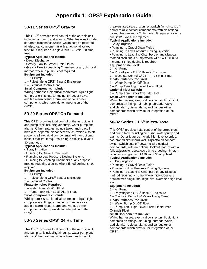
Appendix 1: OPS® Explanation Guide
50-11 Series OPS® Gravity This OPS® provides total control of the aerobic unit including air pump and alarms. Other features include separate disconnect switch (which cuts off power to all electrical components) with an optional lockout feature. It requires a single circuit 120 volt / 20 amp feed. Typical Applications Include: • Direct Discharge • Gravity Flow to Gravel Drain Fields • Gravity Flow to Leaching Chambers or any disposal method where a pump is not required. Equipment Included: 1 – Air Pump 1 – Polyethylene OPS® Base & Enclosure 1 – Electrical Control Panel Small Components Include: Wiring harnesses, electrical connectors, liquid tight compression fittings, air tubing, shraeder valve, audible alarm, visual alarm, and various other components which provide for integration of the OPS®.
50-20 Series OPS® On Demand This OPS® provides total control of the aerobic unit and pump tank including air pump, water pump and alarms. Other features include two-branch circuit breakers, separate disconnect switch (which cuts off power to all electrical components) with an optional lockout feature. It requires a single circuit 120 volt / 30 amp feed. Typical Applications Include: • Spray Irrigation • Pumping to Gravel Drain Fields • Pumping to Low Pressure Dosing Systems • Pumping to Leaching Chambers or any disposal method requiring a pump where timed dosing is not required. Equipment Included: 1 – Air Pump 1 – Polyethylene OPS® Base & Enclosure 1 – Electrical Control Floats Switches Required: 1 – Water Pump On/Off Float 1 – Pump Tank High Level Alarm Float Small Components Include: Wiring harnesses, electrical connectors, liquid tight compression fittings, air tubing, shraeder valve, audible alarm, visual alarm, and various other components which provide for integration of the OPS®.
50-30 Series OPS® 24 Hr. Time
This OPS® provides total control of the aerobic unit and pump tank including air pump, water pump and alarms. Other features include two-branch circuit
breakers, separate disconnect switch (which cuts off power to all electrical components) with an optional lockout feature and a 24 hr. timer. It requires a single circuit 120 volt / 30 amp feed. Typical Applications Include: • Spray Irrigation • Pumping to Gravel Drain Fields • Pumping to Low Pressure Dosing Systems • Pumping to Leaching Chambers or any disposal method requiring a pump where 24 hr. – 15 minute increment timed dosing is required. Equipment Included: 1 – Air Pump 1 – Polyethylene OPS® Base & Enclosure 1 – Electrical Control w/ 24 hr. – 15 min. Timer Floats Switches Required: 1 – Water Pump On/Off Float 1 – Pump Tank High Level Alarm Float Optional Float Switch: 1 – Pump Tank Timer Override Float Small Components Include: Wiring harnesses, electrical connectors, liquid tight compression fittings, air tubing, shraeder valve, audible alarm, visual alarm, and various other components which provide for integration of the OPS®.
50-32 Series OPS® Micro-Dose This OPS® provides total control of the aerobic unit and pump tank including air pump, water pump and alarms. Other features include high-level override, two-branch circuit breakers, separate disconnect switch (which cuts off power to all electrical components) with an optional lockout feature with a fully adjustable repeat cycle (micro-dosing) timer. It requires a single circuit 120 volt / 30 amp feed. Typical Applications Include: • Drip Irrigation • Pumping to Gravel Drain Fields • Pumping to Low Pressure Dosing Systems • Pumping to Leaching Chambers or any disposal method requiring a pump where micro-dosing is desired with single float high level override / high level alarm. Equipment Included: 1 – Air Pump 1 – Polyethylene OPS® Base & Enclosure 1 – Electrical Control w/ Micro-dosing Timer Floats Switches Required: 1 – Water Pump On/Off Float 1 – Pump Tank High Level Alarm Float/Timer Override Float Small Components Include: Wiring harnesses, electrical connectors, liquid tight compression fittings, air tubing, shraeder valve, audible alarm, visual alarm, and various other components which provide for integration of the OPS®.

Appendix 2: Hydro-Action® AP Series Pump Selection
Note: Please see Hydro-Action® Pump Manual for each manufacturer OEM Manual
Description of AP Series Compressor Pumps The Hydro-Action® AP Series ATU’s have several approved types of compressor pumps available. NSF has approved these models and by no means does Hydro-Action® condone the use of any other replacement pump not included on this list. Hydro-Action® uses three which are; Hi-blow Linear, Gast Linear, and Gast Rotary Vane…
AP Series Hi-Blow Gast Gast Model Linear Linear Rotary AP500 HP-80 DBMS80 AT05-101
LPA500 HP-80 DBMS80 AT05-101 AP600 HP-100 LL DBMS100 AT05-101 AP750 HP-120LL DBMS120 AT05-101
AP1000 HP-150 DBMX150 1023-101 AP1500 HP-200 DBMX200 1023-101
Description of AP Series Effluent Pumps The Hydro-Action® AP Series utilize many effluent pumps. NSF does not regulate the pump tank component of NSF std. 40 systems unless it is a component of treatment. Therefore, any comparable pump may be used. Hydro-Action® currently uses Barnes for its standard pump and the mid-suction Hydromatic for all drip irrigation applications. See manuals below for information.
AP Series Barnes Hydromatic Model
Standard SP-33 HE 20-51 Drip Application
High Head 1/2 HP HE 12-51 High Flow 1/2 HP HE 30-51
High Head 1 HP HE 25-10 High Flow 1 HP HE 35-10

Appendix 3: Technical Manual for Timers
Grasslin 24 Hr. Timer Omeron Micro-Dose Timer

Appendix 4: Electrical Controls Schematics
SPI Panels: Used ’08 to Present Model 11 Electrical Controls Schematics.........................................................EC-11 / CP-11 Model 20 Electrical Controls Schematics.........................................................EC-20 / CP-20 Model 30 Electrical Controls Schematics.........................................................EC-30 / CP-30 Model 32 Electrical Controls Schematics.........................................................EC-32 / CP-32

Appendix 5: Drawings
AP 500 ATU………………………............................................................................................
LPA 500 ATU………………………............................................................................................
AP 600 ATU………………………............................................................................................
AP 750 ATU………………………............................................................................................
AP 1000 ATU………………………............................................................................................
AP 1500 ATU………………………............................................................................................
Appendix 6: Misc. Forms & Documents
Do’s and Don’ts………………………………………………………………………………………
Suggested Initial Service Contract...........................................................................................
Suggested Service Call Procedure..........................................................................................
Service Technician Checklist..................................................................................................
Installation Checklist................................................................................................................
Limited Warranty.....................................................................................................................
Warranty Registration..............................................................................................................
Proper use of the Sludge Judge...............................................................................................
Compressor Conversion Instructions………………………………………………………………..
Compressor Serial Number Location………………………………………………………………..
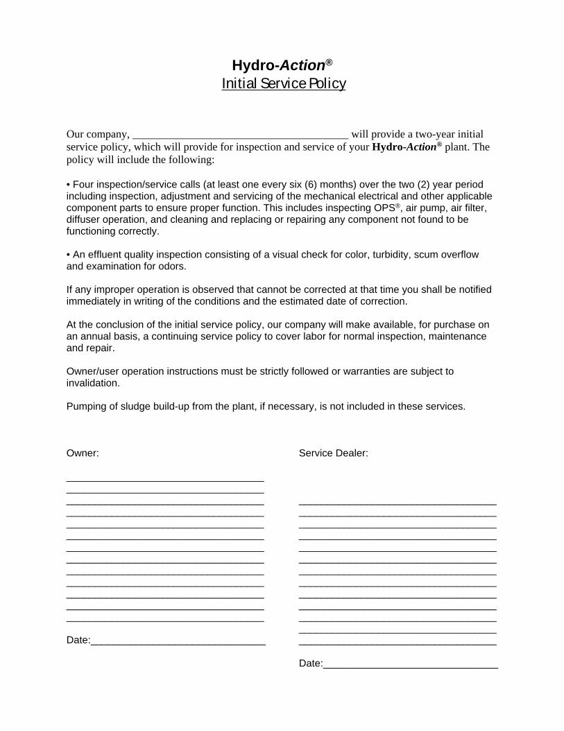
Hydro-Action® Initial Service Policy
Our company, _______________________________________ will provide a two-year initial service policy, which will provide for inspection and service of your Hydro-Action® plant. The policy will include the following: • Four inspection/service calls (at least one every six (6) months) over the two (2) year period including inspection, adjustment and servicing of the mechanical electrical and other applicable component parts to ensure proper function. This includes inspecting OPS®, air pump, air filter, diffuser operation, and cleaning and replacing or repairing any component not found to be functioning correctly. • An effluent quality inspection consisting of a visual check for color, turbidity, scum overflow and examination for odors. If any improper operation is observed that cannot be corrected at that time you shall be notified immediately in writing of the conditions and the estimated date of correction. At the conclusion of the initial service policy, our company will make available, for purchase on an annual basis, a continuing service policy to cover labor for normal inspection, maintenance and repair. Owner/user operation instructions must be strictly followed or warranties are subject to invalidation. Pumping of sludge build-up from the plant, if necessary, is not included in these services. Owner: _______________________________________________________________________________________________________________________________________________________________________________________________________________________________________________________________________________________________________________________________________________________________________________________________________________________________________________________________________ Date:_______________________________
Service Dealer: _______________________________________________________________________________________________________________________________________________________________________________________________________________________________________________________________________________________________________________________________________________________________________________________________________________________________________________________________________ Date:_______________________________
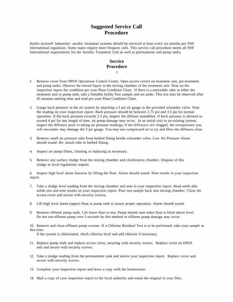
Suggested Service Call Procedure
Hydro-Action® Industries’ aerobic treatment systems should be serviced at least every six months per NSF International regulation. Some states require more frequent calls. This service call procedure meets all NSF International requirements for the Aerobic Treatment Unit as well as pretreatment and pump tanks.
Service
Procedure:
1. Remove cover from OPS® Operations Control Center. Open access covers on treatment unit, pre-treatment
and pump tanks. Observe the mixed liquor in the mixing chamber of the treatment unit. Note on the inspection report the condition per your Plant Condition Chart. If there is a noticeable odor in either the treatment unit or pump tank, take a Settable Solids Test sample and set aside. This test may be observed after 45 minutes settling time and read per your Plant Condition Chart.
2. Gauge back pressure in the air system by attaching a 5 psi air gauge to the provided schraeder valve. Note
the reading on your inspection report. Back pressure should be between 2.75 psi and 3.5 psi for normal operation. If the back pressure exceeds 3.5 psi, inspect the diffuser assemblies. If back pressure is allowed to exceed 4 psi for any length of time, air pump damage may occur. In an initial visit to an existing system, inspect the diffusers prior to taking air pressure readings; if the diffusers are clogged, the overpressure you will encounter may damage the 5 psi gauge. You may use compressed air to try and blow the diffusers clear.
3. Remove small air pressure tube from barbed fitting beside schraeder valve. Low Air Pressure Alarm
should sound. Re- attach tube to barbed fitting.
4. Inspect air pump filters, cleaning or replacing as necessary.
5. Remove any surface sludge from the mixing chamber and clarification chamber. Dispose of this sludge as local regulations require.
6. Inspect high level alarm function by lifting the float. Alarm should sound. Note results in your inspection report.
7. Take a sludge level reading from the mixing chamber and note in your inspection report. Read settle able
solids test and note results on your inspection report. Pour test sample back into mixing chamber. Close the access cover and secure with security screws.
8. Lift high level alarm (upper) float in pump tank to assure proper operation. Alarm should sound.
9. Remove effluent pump stalk. Lift lower float to test. Pump should start when float is lifted above level.
Do not run effluent pump over 5 seconds by this method or effluent pump damage may occur.
10. Remove and clean effluent pump screens. If a Chlorine Residual Test is to be performed, take your sample at this time.
If the system is chlorinated, check chlorine level and add chlorine if necessary.
11. Replace pump stalk and replace access cover, securing with security screws. Replace cover on OPS® unit and secure with security screws.
12. Take a sludge reading from the pretreatment tank and note in your inspection report. Replace cover and
secure with security screws.
13. Complete your inspection report and leave a copy with the homeowner.
14. Mail a copy of your inspection report to the local authority and retain the original in your files.

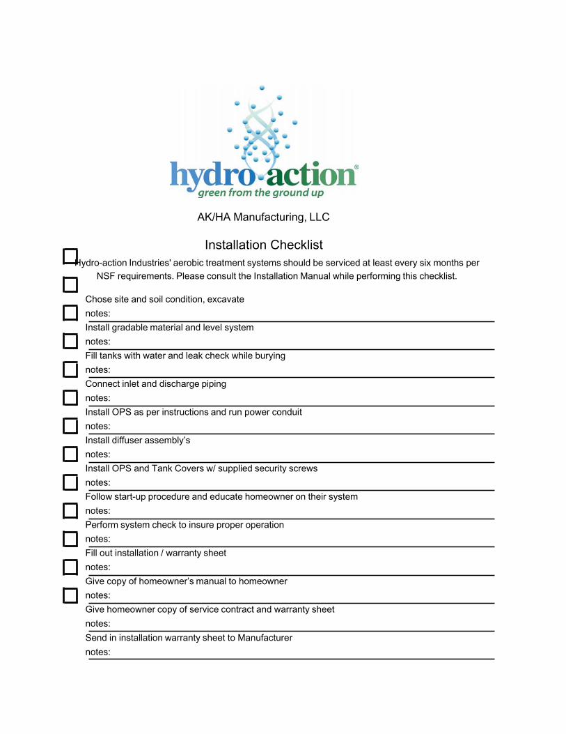
AK/HA Manufacturing, LLC
Service Technician Checklist Hydro-action Industries' aerobic treatment systems should be serviced at least every six months per
NSF requirements. Please consult the Suggested Service Call Procedure and the Operation & Maintenance Manual while performing this checklist.
Remove covers from OPS®, Pre-treat, ATU, and Pump Tank. notes: Note condition of ATU by consulting Plant Condition Chart notes: Perform Settle able Solids Test notes: Gauge back pressure notes: Perform Air Pressure Alarm Check by removing tube from barbed fitting notes: Inspect pump filters notes: Remove any surface sludge from ATU notes: Inspect high level alarms (ATU & Pump Tank) notes: Measure sludge level w/ Sludge Judge (ATU & Pre-treat Tank) notes: Check effluent pump on/off float notes: Check chlorinator & chlorine level notes: Replace covers w/ supplied security screws notes: Complete Inspection Report and make copies for; Homeowner, Local Authority, and Self notes:
AK/HA Manufacturing, LLC
Installation Checklist Hydro-action Industries' aerobic treatment systems should be serviced at least every six months per
NSF requirements. Please consult the Installation Manual while performing this checklist.
Chose site and soil condition, excavate notes: Install gradable material and level system notes: Fill tanks with water and leak check while burying notes: Connect inlet and discharge piping notes: Install OPS as per instructions and run power conduit notes: Install diffuser assembly’s notes: Install OPS and Tank Covers w/ supplied security screws notes: Follow start-up procedure and educate homeowner on their system notes: Perform system check to insure proper operation notes: Fill out installation / warranty sheet notes: Give copy of homeowner’s manual to homeowner notes: Give homeowner copy of service contract and warranty sheet notes: Send in installation warranty sheet to Manufacturer notes:
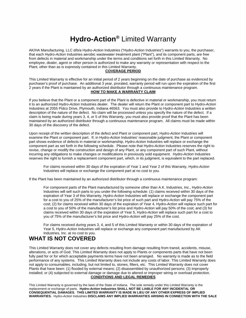
Hydro-Action® Limited Warranty
AK/HA Manufacturing, LLC d/b/a Hydro-Action Industries (“Hydro-Action Industries”) warrants to you, the purchaser, that each Hydro-Action Industries aerobic wastewater treatment plant (“Plant”), and its component parts, are free from defects in material and workmanship under the terms and conditions set forth in this Limited Warranty. No employee, dealer, agent or other person is authorized to make any warranty or representation with respect to the Plant, other than as is expressly contained in this Limited Warranty.
COVERAGE PERIOD This Limited Warranty is effective for an initial period of 2 years beginning on the date of purchase as evidenced by purchaser’s proof of purchase. An additional 3 year, prorated, warranty period will run upon the expiration of the first 2 years if the Plant is maintained by an authorized distributor through a continuous maintenance program.
HOW TO MAKE A WARRANTY CLAIM
If you believe that the Plant or a component part of the Plant is defective in material or workmanship, you must return it to an authorized Hydro-Action Industries dealer. The dealer will return the Plant or component part to Hydro-Action Industries at 2055 Pidco Drive, Plymouth, Indiana 46563. You must also provide to Hydro-Action Industries a written description of the nature of the defect. No claim will be processed unless you specify the nature of the defect. If a claim is being made during years 3, 4, or 5 of this Warranty, you must also provide proof that the Plant has been maintained by an authorized distributor through a continuous maintenance program. All claims must be made within 30 days of the discovery of the defect.
Upon receipt of the written description of the defect and Plant or component part, Hydro-Action Industries will examine the Plant or component part. If, in Hydro-Action Industries’ reasonable judgment, the Plant or component part shows evidence of defects in material or workmanship, Hydro-Action Industries will replace or exchange the component part as set forth in the following schedule. Please note that Hydro-Action Industries reserves the right to revise, change or modify the construction and design of any Plant, or any component part of such Plant, without incurring any obligations to make changes or modifications in previously sold equipment. Hydro-Action Industries reserves the right to furnish a replacement component part, which, in its judgment, is equivalent to the part replaced.
For claims received within 30 days of the expiration of Year 1 and Year 2 of this Warranty, Hydro-Action Industries will replace or exchange the component part at no cost to you.
If the Plant has been maintained by an authorized distributor through a continuous maintenance program:
For component parts of the Plant manufactured by someone other than A.K. Industries, Inc., Hydro-Action Industries will sell such parts to you under the following schedule: (1) claims received within 30 days of the expiration of Year 3 of this Warranty, Hydro-Action Industries will replace or exchange the component part for a cost to you of 25% of the manufacturer’s list price of such part and Hydro-Action will pay 75% of the cost; (2) for claims received within 30 days of the expiration of Year 4, Hydro-Action will replace such part for a cost to you of 50% of the manufacturer’s list price and Hydro-Action will pay 50% of the cost; and (3) for claims received within 30 days of the expiration of Year 5, Hydro-Action will replace such part for a cost to you of 75% of the manufacturer’s list price and Hydro-Action will pay 25% of the cost.
For claims received during years 3, 4, and 5 of this Limited Warranty or within 30 days of the expiration of Year 5, Hydro-Action Industries will replace or exchange any component part manufactured by AK Industries, Inc. at no cost to you.
WHAT IS NOT COVERED
This Limited Warranty does not cover any defects resulting from damage resulting from transit, accidents, misuse, alterations, or acts of God. This Limited Warranty does not apply to Plants or components parts that have not been fully paid for or for which acceptable payments terms have not been arranged. No warranty is made as to the field performance of any systems. This Limited Warranty does not include any costs of labor. This Limited Warranty does not apply to consumables, including, but not limited to, stones, filters, etc. This Limited Warranty does not cover Plants that have been: (1) flooded by external means; (2) disassembled by unauthorized persons; (3) improperly installed; or (4) subjected to external damage or damage due to altered or improper wiring or overload protection.
CONDITIONS AND LEGAL REMEDIES This Limited Warranty is governed by the laws of the State of Indiana. The sole remedy under this Limited Warranty is the replacement or exchange of parts. Hydro-Action Industries SHALL NOT BE LIABLE FOR ANY INCIDENTAL OR CONSEQUENTIAL DAMAGES. THIS LIMITED WARRANTY IS MADE IN LIEU OF ANY OTHER EXPRESS OF IMPLIED WARRANTIES. Hydro-Action Industries DISCLAIMS ANY IMPLIED WARRANTIES ARISING IN CONNECTION WITH THE SALE
OF THE PLANT, INCLUDING ANY IMPLIED WARRANTIES OF MERCHANTABILITY OR FITNESS FOR A PARTICULAR PURPOSE. Some states do not allow the disclaimer of warranties or the exclusion or limitation of incidental or consequential damages and so the above limitations may not apply to you.
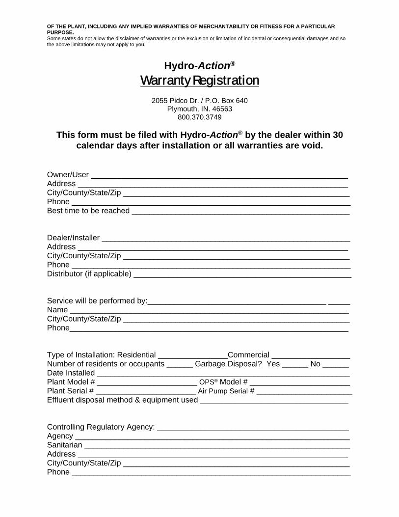
Hydro-Action®
Warranty Registration
2055 Pidco Dr. / P.O. Box 640 Plymouth, IN. 46563
800.370.3749
This form must be filed with Hydro-Action® by the dealer within 30 calendar days after installation or all warranties are void.
Owner/User ___________________________________________________________ Address ______________________________________________________________ City/County/State/Zip ____________________________________________________ Phone ________________________________________________________________ Best time to be reached __________________________________________________ Dealer/Installer _________________________________________________________ Address ______________________________________________________________ City/County/State/Zip ____________________________________________________ Phone ________________________________________________________________ Distributor (if applicable) __________________________________________________ Service will be performed by:_________________________________________ _____ Name ________________________________________________________________ City/County/State/Zip ____________________________________________________ Phone________________________________________________________________ Type of Installation: Residential ________________Commercial __________________ Number of residents or occupants ______ Garbage Disposal? Yes ______ No ______ Date Installed __________________________________________________________ Plant Model # _______________________ OPS® Model # _______________________ Plant Serial # _______________________ Air Pump Serial # ______________________ Effluent disposal method & equipment used __________________________________ Controlling Regulatory Agency: ____________________________________________ Agency _______________________________________________________________ Sanitarian _____________________________________________________________ Address ______________________________________________________________ City/County/State/Zip ____________________________________________________ Phone ________________________________________________________________
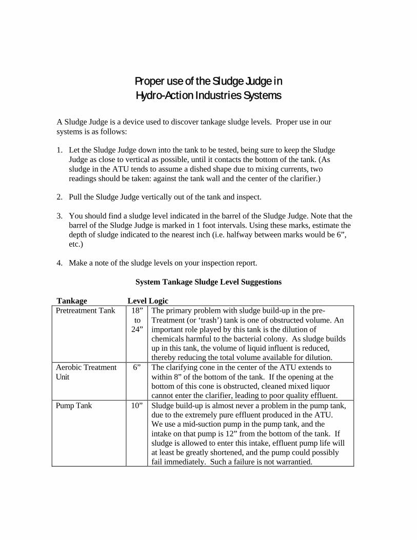
Proper use of the Sludge Judge in Hydro-Action Industries Systems
A Sludge Judge is a device used to discover tankage sludge levels. Proper use in our systems is as follows:
1. Let the Sludge Judge down into the tank to be tested, being sure to keep the Sludge
Judge as close to vertical as possible, until it contacts the bottom of the tank. (As sludge in the ATU tends to assume a dished shape due to mixing currents, two readings should be taken: against the tank wall and the center of the clarifier.)
2. Pull the Sludge Judge vertically out of the tank and inspect.
3. You should find a sludge level indicated in the barrel of the Sludge Judge. Note that the
barrel of the Sludge Judge is marked in 1 foot intervals. Using these marks, estimate the depth of sludge indicated to the nearest inch (i.e. halfway between marks would be 6”, etc.)
4. Make a note of the sludge levels on your inspection report.
System Tankage Sludge Level Suggestions
Tankage Level Logic
Pretreatment Tank 18” to
24”
The primary problem with sludge build-up in the pre- Treatment (or ‘trash’) tank is one of obstructed volume. An important role played by this tank is the dilution of chemicals harmful to the bacterial colony. As sludge builds up in this tank, the volume of liquid influent is reduced, thereby reducing the total volume available for dilution.
Aerobic Treatment Unit
6” The clarifying cone in the center of the ATU extends to within 8” of the bottom of the tank. If the opening at the bottom of this cone is obstructed, cleaned mixed liquor cannot enter the clarifier, leading to poor quality effluent.
Pump Tank 10” Sludge build-up is almost never a problem in the pump tank, due to the extremely pure effluent produced in the ATU. We use a mid-suction pump in the pump tank, and the intake on that pump is 12” from the bottom of the tank. If sludge is allowed to enter this intake, effluent pump life will at least be greatly shortened, and the pump could possibly fail immediately. Such a failure is not warrantied.
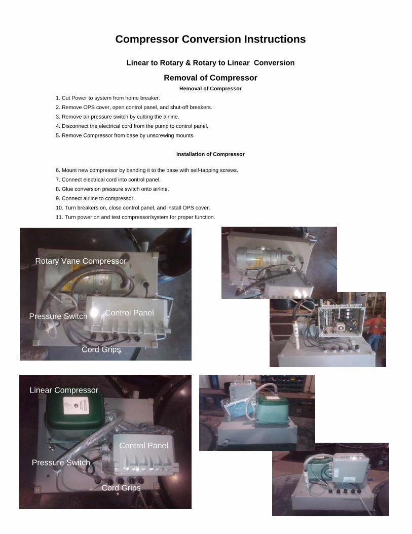
Compressor Conversion Instructions
Linear to Rotary & Rotary to Linear Conversion
Removal of Compressor Removal of Compressor
1. Cut Power to system from home breaker.
2. Remove OPS cover, open control panel, and shut-off breakers.
3. Remove air pressure switch by cutting the airline.
4. Disconnect the electrical cord from the pump to control panel.
5. Remove Compressor from base by unscrewing mounts.
Installation of Compressor
6. Mount new compressor by banding it to the base with self-tapping screws.
7. Connect electrical cord into control panel.
8. Glue conversion pressure switch onto airline.
9. Connect airline to compressor.
10. Turn breakers on, close control panel, and install OPS cover.
11. Turn power on and test compressor/system for proper function.
Linear Compressor
Rotary Vane Compressor
Cord Grips
Cord Grips
Pressure Switch
Pressure Switch
Control Panel
Control Panel
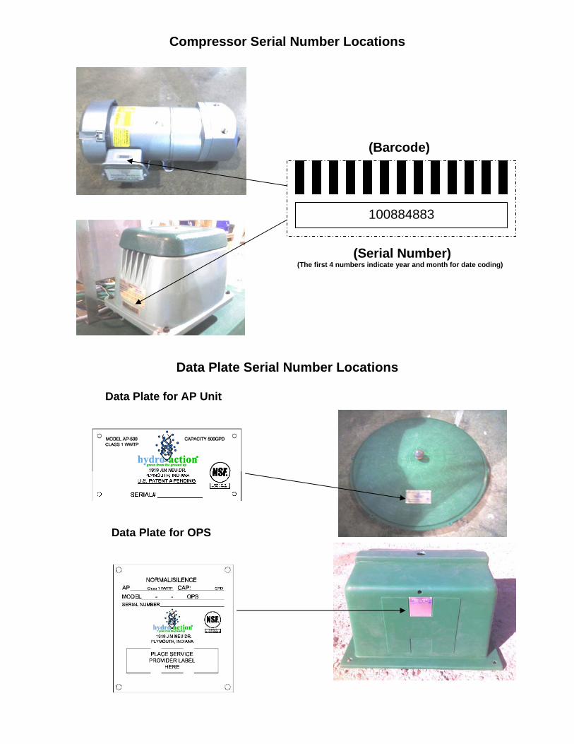
Compressor Serial Number Locations
(Barcode)
(Serial Number) (The first 4 numbers indicate year and month for date coding)
Data Plate Serial Number Locations
Data Plate for AP Unit
Data Plate for OPS
100884883
AK/HA Manufacturing LLC.
2055 Pidco Dr. / P.O. Box 640 Plymouth, IN. 46563-1374
Toll Free: 800.370.3749 Phone: 574.936.2542 Fax: 574.936.2298
www.hydro-action.com
01/14