operation & maintenance of hvdc station...
TRANSCRIPT
OPERATION & MAINTENANCE
OF
HVDC
STATION
Praveen Ranjan
Resident Project Manager
India-Bangladesh Inter-connector Project
Powergrid Corporation Of India Ltd.

Incorporated in 1989 for transmission of Electric Power across the country.
Central Transmission Utility - Navaratna PSU
Asset over Rs. 56000 Crs
World's Leading Power Transmission Utility (3rd)
POWERGRID, An OVERVIEW
76800 Ckt.Km line-128 Substations
Technology Leader in EHVAC & HVDC Transmission.
Carries more than 50% of Generated Power Across Country.
84500 MVA Transformation Capacity
22400 MW Interregional Capacity Telecom NLD with 21000 Km Optical Fibre Network & Internet Service Provider
POWERGRID, An OVERVIEW
ROURKELA
RAIPURHIRMA
TALCHER
JAIPUR
NER
ER
WR
NR
SR
B'SHARIF
ALLAHABAD
SIPAT
GAZUWAKA
JEYPORECHANDRAPUR
SINGRAULI
VINDHYA-
2000
MW
2000MW
2500MW
1000MW
500MW
LUCKNOW
DIHANG
CHICKEN NECK
TEESTA
TIPAIMUKH
BADARPUR
MISA
DAMWE
KATHAL-GURI
LEGEND
765 KV LINES
400 KV LINES
HVDC B/B
HVDC BIPOLE
EXISTING/ X PLAN NATIONAL
ZERDA
HISSAR
BONGAIGAON
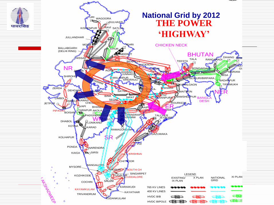
DEVELOPMENT OF NATIONAL GRID
KOLHAPUR
NARENDRA
KAIGA
PONDA
IX PLAN
MARIANI
NORTH
KAHALGAON
RANGANADI
SEONI
CHEGAON
BHANDARA
DEHGAM
KARAD
LONIKAND
VAPI
GANDHAR/
TALA
BANGLA
BALLABGARH A'PUR(DELHI RING)
BANGALORE
KOZHIKODE
COCHIN
KAYAMKULAM
TRIVANDRUM
PUGALUR
KAYATHAR
KARAIKUDI
CUDDALORE
SOUTH CHENNAI
KRISHNAPATNAM
CHITTOOR
VIJAYAWADA
SINGARPET
PIPAVAV
LIMBDI
KISHENPUR
DULHASTI
WAGOORA
MOGA
URI
BHUTAN
RAMAGUNDAM
SATLUJRAVI
JULLANDHAR
DESH
VARANASI/UNNAO
M'BAD
PURNEA
KORBA
NAGDA
SILIGURI/BIRPARA
LAK
SH
AD
WE
EP
TEHRI
MEERUT
BHIWADI
BINA
SATNA
MALANPURSHIROHI
KAWAS
AMRAVATI
AKOLA
AGRA
SIRSI
CHAL
JETPURAMRELI
BOISARTARAPUR
PADGHE
DHABOL
KOYNA
BARH
G'PUR
HOSURMYSORE
KUDANKULAM
M'PUR
KARANPURA
MAITHON
JAMSHEDPUR
PARLI
WARDA
BEARILLY
SALEM GRID
XI PLAN
765 KV LINES IN X PLAN. TO BE CHARGED AT 400KV INITIALLY
TO BE CHARGED AT 765 KV UNDER NATIONAL GRID
National Grid by 2012 THE POWER
‘HIGHWAY’
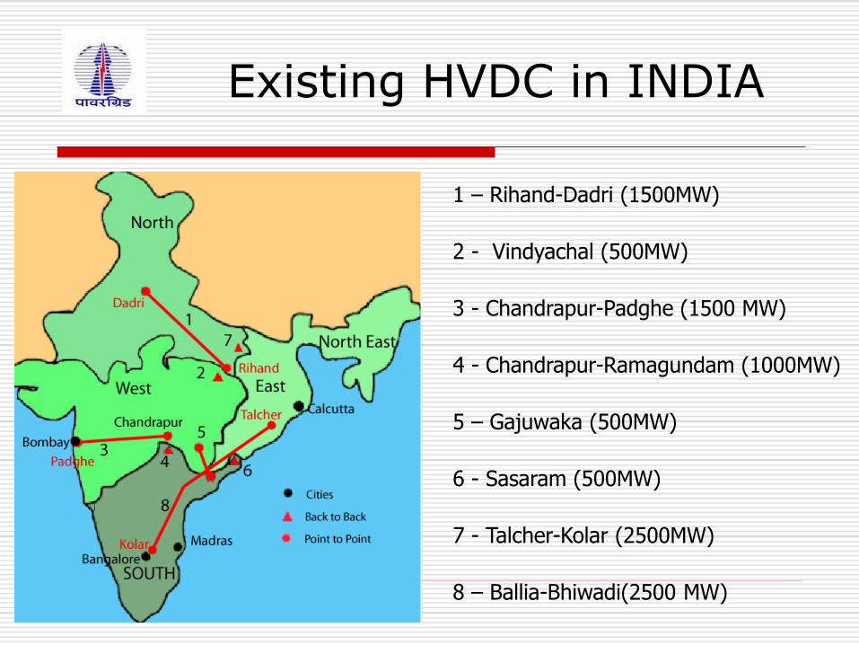
Existing HVDC in INDIA
1 – Rihand-Dadri (1500MW)
2 - Vindyachal (500MW)
3 - Chandrapur-Padghe (1500 MW)
4 - Chandrapur-Ramagundam (1000MW)
5 – Gajuwaka (500MW)
6 - Sasaram (500MW)
7 - Talcher-Kolar (2500MW)
8 – Ballia-Bhiwadi(2500 MW)
SALIENT FEATURES OF EXISTING &
UPCOMING HVDC STATIONS

± 500 kV , 1500 MW Rihand – Dadri HVDC Project.
Approx. Value of the Contract: Rs. 457 Crore
Main Data:
Power rating : 1500MW
No. of Poles : 2
AC Voltage : 400 kV
DC Voltage : + 500 kV
Converter Transformer-
Rihand Terminal : 6 x 315 MVA
Dadri Terminal : 6 x 315 MVA
Length of over head DC line: 816 KM.
Start date: Feb-1986
Completion date: Dec-1991
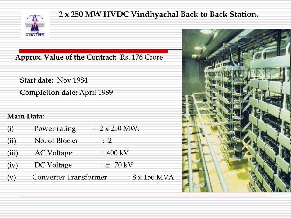
2 x 250 MW HVDC Vindhyachal Back to Back Station.
Approx. Value of the Contract: Rs. 176 Crore
Start date: Nov 1984
Completion date: April 1989
Main Data:
(i) Power rating : 2 x 250 MW.
(ii) No. of Blocks : 2
(iii) AC Voltage : 400 kV
(iv) DC Voltage : ± 70 kV
(v) Converter Transformer : 8 x 156 MVA

2 x 500 MW HVDC Chandrapur Back to Back Station.
Start date: November 1993
Completion date: Dec 1997
Main Data:
Power rating : 2 x 500 MW.
No. of Blocks : 2
AC Voltage : 400 kV
DC Voltage : + 205 Kv
Converter Transformer : 12 x 234 MVA
Approx. Value of the Contract: Rs. 702.78 Crore
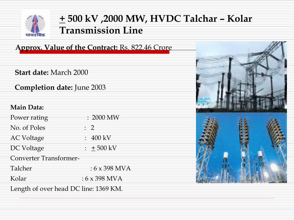
+ 500 kV ,2000 MW, HVDC Talchar – Kolar Transmission Line
Approx. Value of the Contract: Rs. 822.46 Crore
Start date: March 2000
Completion date: June 2003
Main Data:
Power rating : 2000 MW
No. of Poles : 2
AC Voltage : 400 kV
DC Voltage : + 500 kV
Converter Transformer-
Talcher : 6 x 398 MVA
Kolar : 6 x 398 MVA
Length of over head DC line: 1369 KM.
HVDC Talchar – Kolar link was designed for 2000 MW continuous rating
with inherent short term overload capacity depending on-
Ambient temperature
Prevailing voltages at Talcher and Kolar
Cooling mechanism.
Further, DC Bipole lines with quad conductor was capable to transmit 1250
MW continuously with marginal incremental loss .
The inherent overload capability was utilized to meet the system
contingencies by up gradation of Talcher – Kolar HVDC link capacity from
2000 MW to 2500 MW .
This enhanced capacity is to be used only under contingency and not for
increasing HVDC Capacity for firm transfer of 2500 MW
Up gradation of + 500 kV HVDC Talchar – Kolar link from 2000 MW to 2500 MW

•Main objective of this HVDC project is to transfer power from Talcher Super
Thermal Power Station (Eastern Region), to Kolar (Southern Region) of Indian
Grid
•The most important features of the project are
•-Better over all economy as compared to AC Transmission
•-Halved right-of-way requirements,
•-Lower transmission loses, better stability and controllability.
• This is the longest (1369 KM.) commercial HVDC link in India.
Talchar – Kolar HVDC Transmission Link
Salient Features:
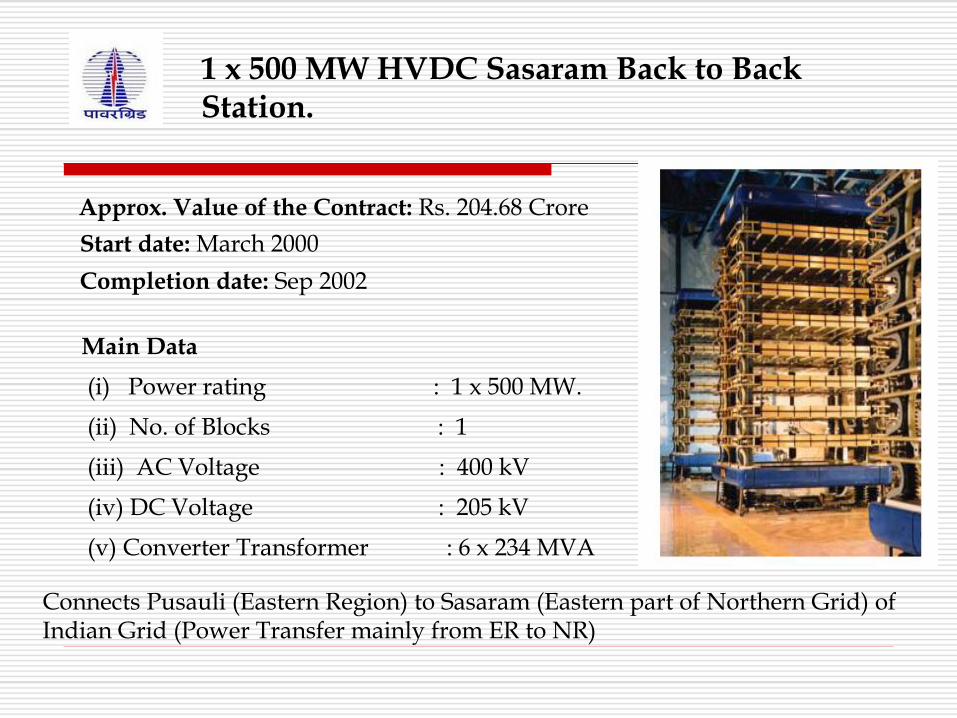
1 x 500 MW HVDC Sasaram Back to Back Station.
Approx. Value of the Contract: Rs. 204.68 Crore
Start date: March 2000
Completion date: Sep 2002
Main Data
(i) Power rating : 1 x 500 MW.
(ii) No. of Blocks : 1
(iii) AC Voltage : 400 kV
(iv) DC Voltage : 205 kV
(v) Converter Transformer : 6 x 234 MVA
Connects Pusauli (Eastern Region) to Sasaram (Eastern part of Northern Grid) of Indian Grid (Power Transfer mainly from ER to NR)
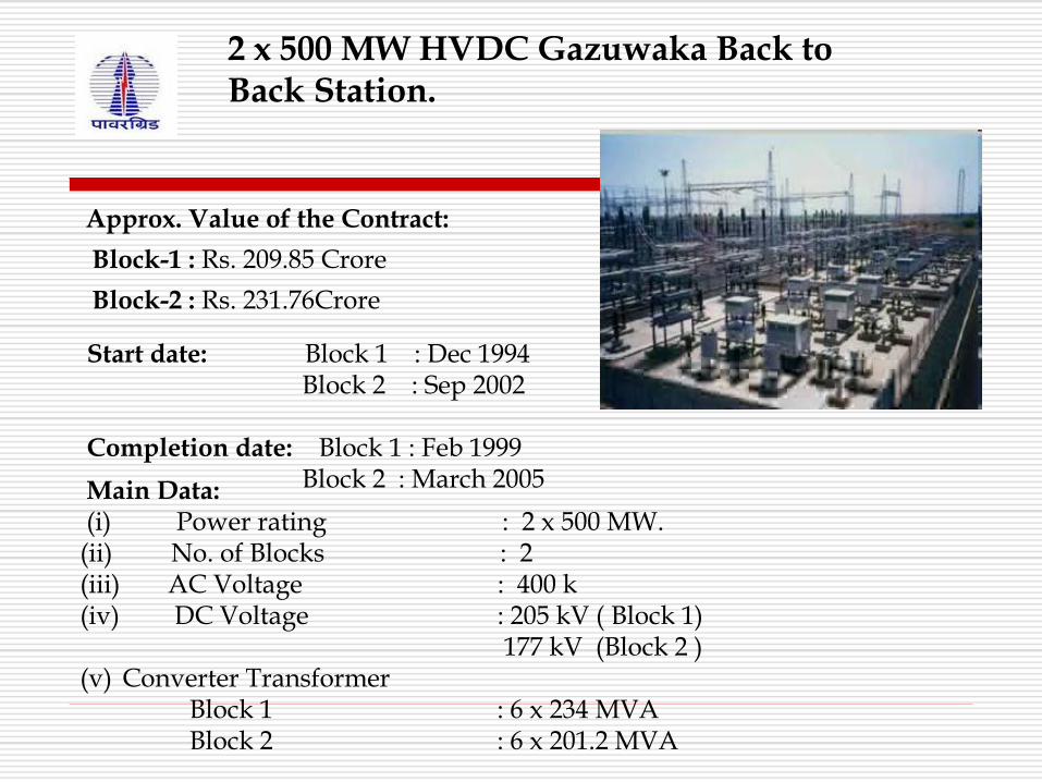
2 x 500 MW HVDC Gazuwaka Back to Back Station.
Approx. Value of the Contract:
Block-1 : Rs. 209.85 Crore
Block-2 : Rs. 231.76Crore
Start date: Block 1 : Dec 1994 Block 2 : Sep 2002 Completion date: Block 1 : Feb 1999 Block 2 : March 2005 Main Data:
(i) Power rating : 2 x 500 MW. (ii) No. of Blocks : 2 (iii) AC Voltage : 400 k (iv) DC Voltage : 205 kV ( Block 1) 177 kV (Block 2 ) (v) Converter Transformer Block 1 : 6 x 234 MVA Block 2 : 6 x 201.2 MVA
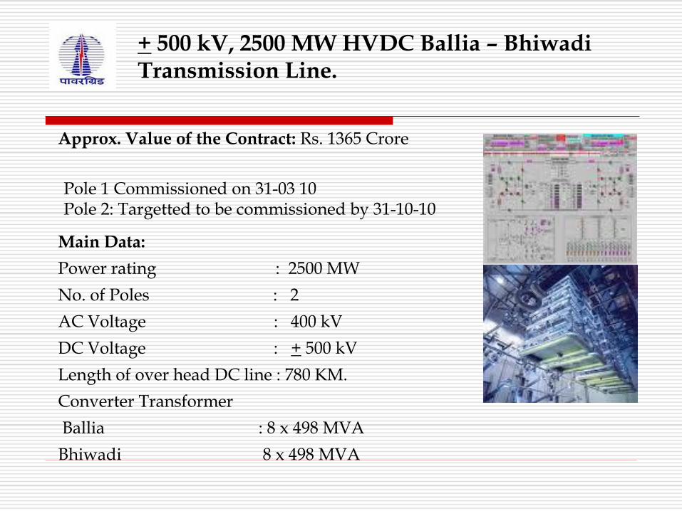
+ 500 kV, 2500 MW HVDC Ballia – Bhiwadi Transmission Line.
Approx. Value of the Contract: Rs. 1365 Crore
Pole 1 Commissioned on 31-03 10 Pole 2: Targetted to be commissioned by 31-10-10
Main Data:
Power rating : 2500 MW
No. of Poles : 2
AC Voltage : 400 kV
DC Voltage : + 500 kV
Length of over head DC line : 780 KM.
Converter Transformer
Ballia : 8 x 498 MVA
Bhiwadi 8 x 498 MVA
HVDC Multi Terminal System
North-Eastern Region has a large quantum Hydro Electric Power
potential.
Under Hydro Development program of Govt of India, this power to be
evacuated to load centres of Northern and Western Regions
POWERGRID installing +/-800 kV, 6000 MW HVDC multi-terminal
system of approx length of 1728 km from North Eastern Region to
Agra.
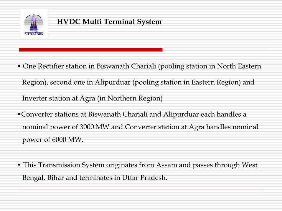
• One Rectifier station in Biswanath Chariali (pooling station in North Eastern
Region), second one in Alipurduar (pooling station in Eastern Region) and
Inverter station at Agra (in Northern Region)
HVDC Multi Terminal System
•Converter stations at Biswanath Chariali and Alipurduar each handles a
nominal power of 3000 MW and Converter station at Agra handles nominal
power of 6000 MW.
• This Transmission System originates from Assam and passes through West
Bengal, Bihar and terminates in Uttar Pradesh.
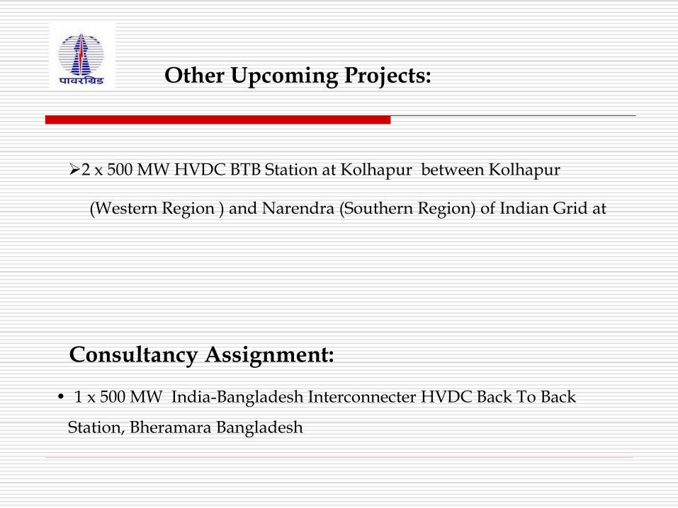
Consultancy Assignment:
• 1 x 500 MW India-Bangladesh Interconnecter HVDC Back To Back
Station, Bheramara Bangladesh
Other Upcoming Projects:
2 x 500 MW HVDC BTB Station at Kolhapur between Kolhapur
(Western Region ) and Narendra (Southern Region) of Indian Grid at
Why O&M?
To Run the system Smoothly to achieve highest availability and avoid outages

Operation of HVDC Station
Preconditions of RFS / RFO
Circuit Breaker Is Closed
Cooling System is OK
No Alarm from Protection System

Operation of HVDC Station
Selection of Mode of Operation
Joint / Separate
Power / Current
Selection of Direction (Applicable for BTB)
Setting the Ramp Rate
Start of Block at Minimum Power Design
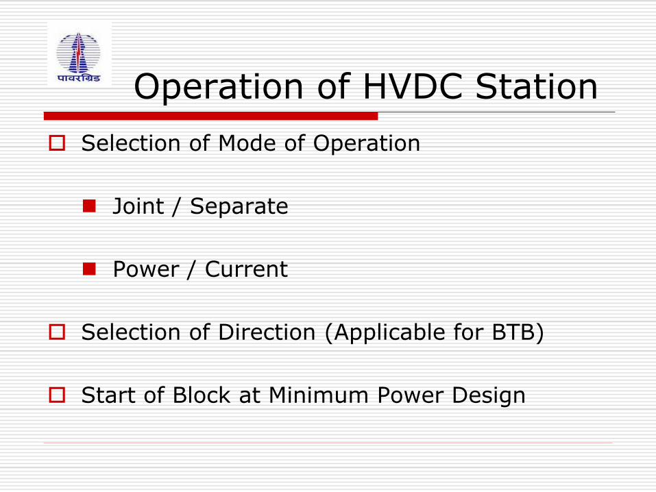
Operation of HVDC Station
Selection of Mode of Operation
Joint / Separate
Power / Current
Selection of Direction (Applicable for BTB)
Start of Block at Minimum Power Design
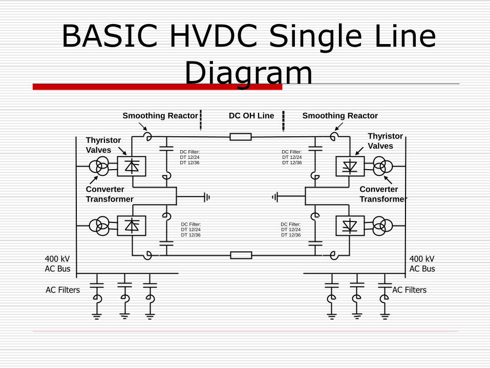
BASIC HVDC Single Line Diagram
DC OH Line
Converter
Transformer
DC Filter: DT 12/24 DT 12/36
DC Filter: DT 12/24 DT 12/36
Thyristor
Valves
400 kV AC Bus
AC Filters
Smoothing Reactor
Converter
Transformer
DC Filter: DT 12/24 DT 12/36
DC Filter: DT 12/24 DT 12/36
Thyristor
Valves
400 kV AC Bus
AC Filters
Smoothing Reactor
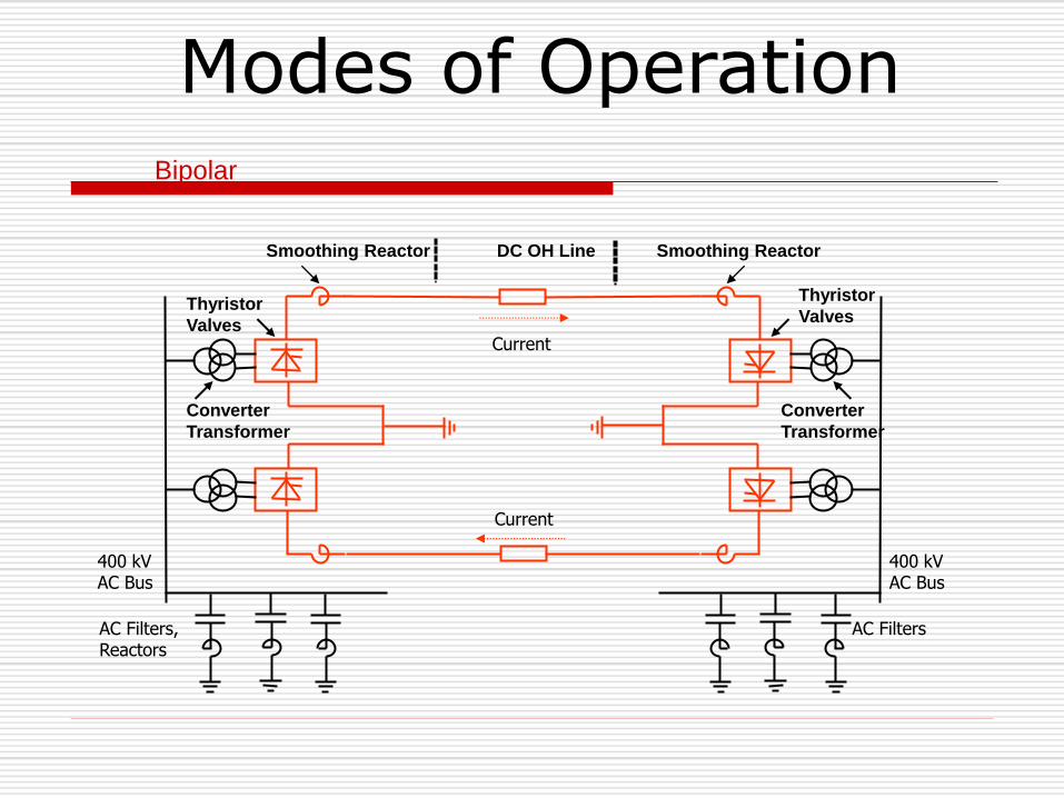
Modes of Operation
DC OH Line
Converter
Transformer
Thyristor
Valves
400 kV AC Bus
AC Filters, Reactors
Smoothing Reactor
Converter
Transformer
Thyristor
Valves
400 kV AC Bus
AC Filters
Smoothing Reactor
Bipolar
Current
Current
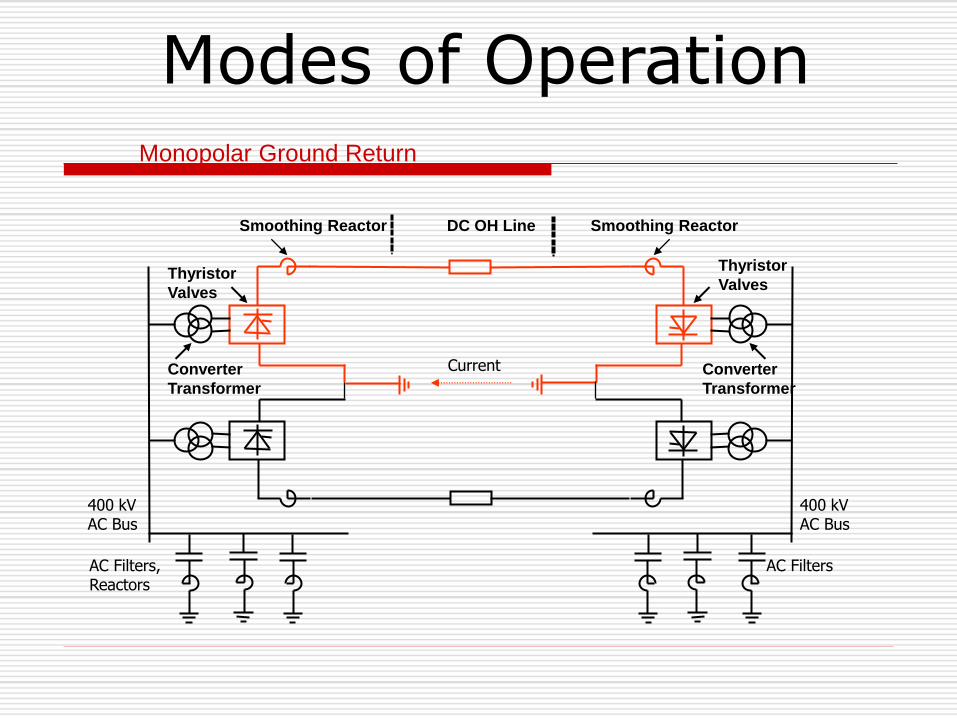
Modes of Operation
DC OH Line
Converter
Transformer
Thyristor
Valves
400 kV AC Bus
AC Filters, Reactors
Smoothing Reactor
Converter
Transformer
Thyristor
Valves
400 kV AC Bus
AC Filters
Smoothing Reactor
Monopolar Ground Return
Current

Modes of Operation
DC OH Line
Converter
Transformer
Thyristor
Valves
400 kV AC Bus
AC Filters, Reactors
Smoothing Reactor
Converter
Transformer
Thyristor
Valves
400 kV AC Bus
AC Filters
Smoothing Reactor
Monopolar Metallic Return
Current

Operation of HVDC Station
Type of Shutdowns
Planned / Forced / Emergency Shutdown

RPC
Q Mode
V Mode
Auto / Manual
Operation of HVDC Station
Shutdown Procedure of HVDC Station Planned
Emergency
Charging Procedure After Shutdown
Checking of Annunciation List Before Charging After
Shutdown (Must)
Operation of HVDC Station
Trouble Shooting
Alarm System
Active & Standby System of C&P

Type of Maintenance
Preventive Maintenance
Outage Maintenance
Major Areas Of HVDC BTB Station
Valve Hall
AC Switchyard Equipments
Valve Cooling
Auxiliaries and AC System
AC/DC Control & Protection System
Valve Hall
The status of the Thyristor levels in the valve hall is available
online in the Control Room
Valve Control System monitors continuously, the healthiness of
the thyristors and associated valve hall components while in
service
Failure of thyristor is reported in the Control Room by Valve
control system for the operator
Alarm is generated up to 2 thyristor failures in a valve and on
3rd failure, trip is generated (Redundancy of Thyristors differs
from system to system)
Failure may be in
Thyristor
Snubber capacitor
Snubber resistor
TE card
To test the thyristor level – Thyristor Level Test
Unit is used which tests thyristor and associated
components
Failure of the thyristor can be detected
Valve Hall – Thyristor level testing
Major Work During Yearly Maintenance
Cleaning of Valve Hall
Testing of Thyristors/Snubber Circuit Testing of Ground Switches
Checking of any abnormality Checking of Water leakage
Tightness Checking of Bolts
Record of Valve Arrestor Readings
Testing of Fire System
AC SWITCHYARD EQUIPMENTS
Converter Transformer
Following tests are done during yearly shutdown
Capacitance and tan δ of the bushings
Used to determine the healthiness of the bushing insulation
Checking the operation of the buchholz relays and Pressure Relief
Devices (PRD)
Checking of the WTI & OTI alarms and trips
Checking whether all the alarms are reported to HMI system
Checking the operation of fire fighting deluge valve system
Converter Transformer
Replacement of the oil filters of OLTC (On-Load tap Changer) –
can be replaced online when the alarm is generated
Periodic testing of the oil – DGA – to determine the incipient
internal faults of the transformer
Testing of all the associated protection relays

Converter Transformer OLTC – Inspection of the OLTC
Maintenance of OLTC after every 1 lakh operations
Wear and tear of all mechanical & electrical parts of the
OLTC to be inspected.
Replacement of mechanical parts with high wear & Tear.
Cleaning of Fixed and moving contacts.
Cleaning of OLTC chambers
Filling with fresh oil
Converter Transformer
Following Maintenance Carried Out W/SD on Monthly Basis
Inspection of Bushing Oil Level.
Inspection of Oil Level in Conservator.
Inspection of Oil Level in OLTC Conservator.
Manual Starting of Oil Pumps & Fans
Checking of Oil Leaks
Oil Level in Breather Oil Seal
Condition of Silica Gel
Converter Transformer
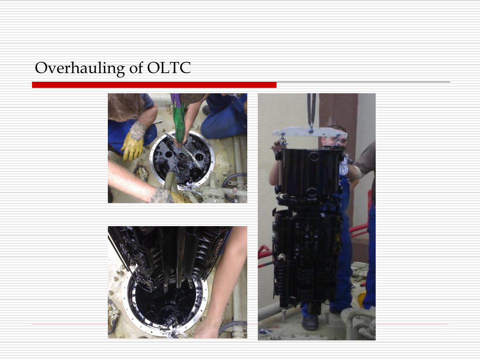
Overhauling of OLTC
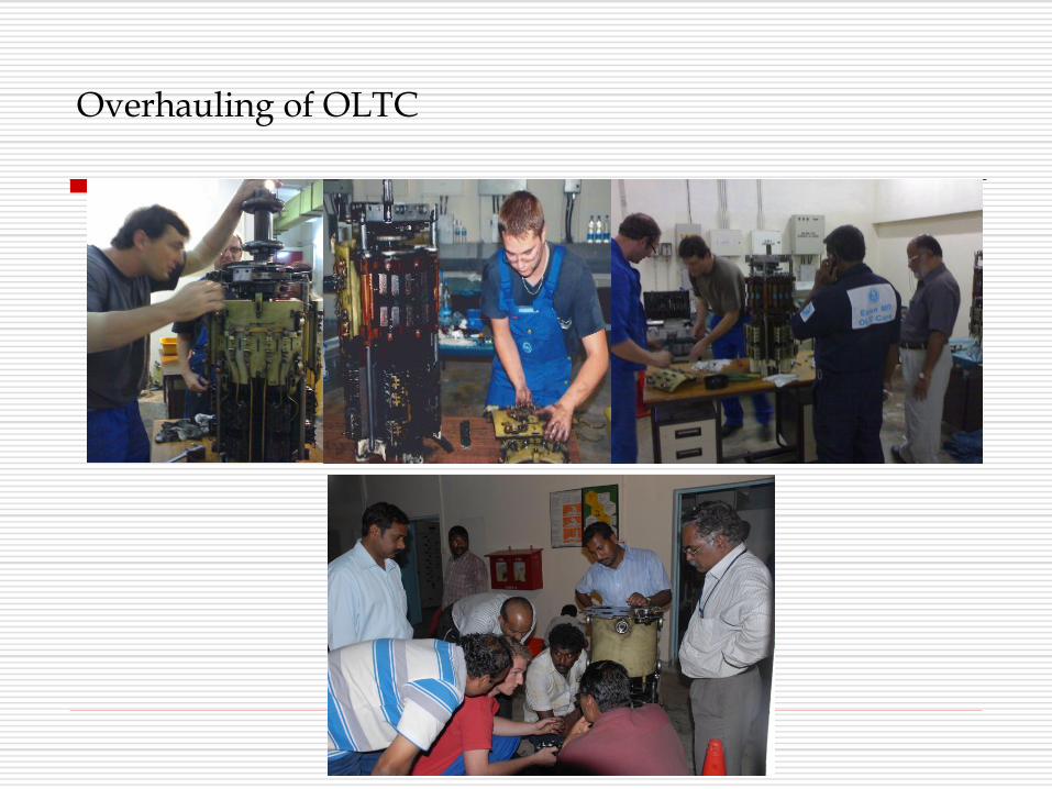
Overhauling of OLTC

AC Filter
Maintenance of filter bay equipment includes
Testing of CT – C & Tan δ
Capacitance stack measurement and balancing if required
Inspection of capacitor stack for oil leakage
Associated breaker testing -Operation timings, alarm,
lockout checks etc.
Measurement of resistors and reactors – for deviation
Testing of associated protection systems
Apart from the yearly maintenance, failure of capacitor cans
calls for
Measurement of individual capacitor stacks /cans
AC Filter
Current Transformer & Voltage Transformer
Current Transformer
Capacitance and Tan δ Measurement (S/D)
Inspection of CT for oil leakage & Crack in Insulator
Cleaning of MB (S/D)
Measurement of Ratio & Secondary Resistance (SOS)
DGA of Oil (SOS)
Oil Parameters (SOS)
IR Measurement (SOS)
Current Transformer & Voltage Transformer
Voltage Transformer
Capacitance and Tan δ Measurement (S/D)
Inspection of oil leakage & Crack in Insulator
Cleaning of MB (S/D)
Measurement of Secondary Voltage
Circuit Breakers
Timing of Main & Auxiliary Contacts (Y)
Checking of Pressure Setting of Switches (Y)
Checking of Pole Discrepancy (Y)
Checking of Interlocks (Y)
Trip / Close Coil Currents Measurement
Maintenance of Air Compressor (In Pneumatic System)
Cleaning of Support Insulator / PIR & Grading Capacitor /
Interrupter Chamber

Circuit Breaker Contd.
Lubrication of Chain & Gears / Checking healthiness & Cleaning of
Rollers / Checking healthiness of springs and greasing if required (In
Spring Operated Mechanism)
Measurement of Static contact resistance measurement (2Y)
Measurement of DCRM & Contact Travel (2Y)
Capacitance & Tan Delta Measurement of Grading Capacitor (4Y)
Dew Point Measurement of SF6 Gas (4Y)
SF6 Gas Filling (SOS)
Checking of Grading Capacitor Oil Leakage (M)
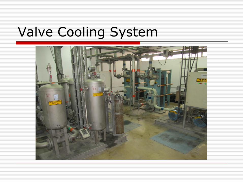
Valve Cooling System
Valve cooling
Maintenance of Valve Cooling
Replacement of resin in the resin chamber yearly
Cleaning / Painting of Cooling Towers (If available)
(Y)
Cleaning of Heat Exchangers (If available) (Y)
Valve Cooling
Cleaning of Filters (SOS)
Testing of Related Protection System
(Y)
Maintenance of Pumps (3M)
Vibration Measurement of Pumps (3M)
Cleaning of Electrical Contactors (3M)

Auxiliary System
Yearly servicing of DG sets and protection relays
testing
Fire Fighting system – checking the hydrant points
Maintenance of station batteries, chargers and UPS
systems
LT system – Relay testing & LT breaker
maintenance
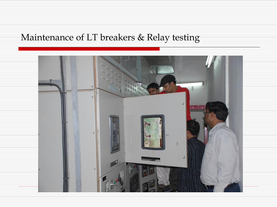
Maintenance of LT breakers & Relay testing
Control & Protection System
Testing of All Control & Protection System (Y)
Modification / Replacement / Testing of Relays & Cards (SOS)
MAJOR PROBLEMS OBSERVED DURING O&M
VALVE HALL
Thyristor Failure (Frequency :Very Low)
Failure of Surge Arrestor (Frequency :Very Low)
Water Leakage from Pex Tube (Frequency :Very Low)
MAJOR PROBLEMS OBSERVED DURING O&M
VALVE COOLING SYSTEM
Water Pump Motor Failure (Frequency :Medium)
Valve Motor Failure (Frequency :Very Low)
Makeup Water Float Failure (Frequency :Medium)

MAJOR PROBLEMS OBSERVED DURING O&M
Control & Protection SYSTEM
Failure of Control Cards
Stalling of Software
Measuring System