operation & maintenance manual - tmg- · pdf fileoperation & maintenance manual ......
TRANSCRIPT
Technify Motors GmbHPlatanenstraße 14
D - 09356 St. Egidien
Tel. +49 37204 696-0Fax +49 37204 [email protected]
Operation & Maintenance Manual
CD-135CD-155
Doc. No.: OM-02-02Version: 4/6
CAUTION:The Operation and Maintenance Manual
must be read completely before operating the engine, as it contains important safety information and information about the operation of the engine.
Note:Please report any service difficulties to the Technical
Support Center at Technify Motors GmbH. See above for contact information.
Note:The Operation and Maintenance Manual
must be included at the time of sale of the engine / aircraft.
Operation & Maintenance Manual - Issue 4 / Revision 6
P/N: 05-7200-H200221

This page intentionally left blank

Operation & Maintenance ManualCD-135 / CD-155
OM-02-02
Table of Contents
Chapter Description Page
Table of Contents .....................................................3List of Figures .........................................................11
0.1 List of Revisions .......................................................10.2 List of applicable Chapters .......................................70.3 Preliminary Remarks ................................................8
1 Introduction ............................................................1
1.1 Accompanying applicable Document .......................1
1.2 Engine Identification .................................................2
1.3 Copyright © ..............................................................3
1.4 Safety Recommendations ........................................3
1.5 Validity of this Manual ..............................................3
1.6 Abbreviations ...........................................................3
1.7 Packaging and Transport .........................................4
1.8 Storage .....................................................................4
1.9 Scope of Supply .......................................................5
1.10 Qualifications of the Operating and Maintenance Personnel .................................................................5
1.11 Update Information Service ......................................5
1.12 Service Life of this Engine ........................................5
1.13 Safety Information ....................................................6
2 Description and Dimensions of the Engine .........1
2.1 Engine Designation ..................................................1
2.2 Description and Standard Production Version .........1
2.3 Engine Views ...........................................................2
Revision no.:Revision date:
Chapter:Issue:Issue date:Page:Content:
02-OM-00-02430.07.201438
622.04.2016
Operation & Maintenance ManualCD-135 / CD-155
OM-02-02
3 Technical Data ........................................................1
3.1 Dimensions and Weights .........................................1
3.2 Performance Data ....................................................1
3.3 Operational Data ......................................................2
3.4 Operation Limits .......................................................2
3.5 Fuel / Oil / Coolant ...................................................4
3.6 Power Curve ............................................................8
3.7 Low Temperature Data and Climate Classes of Diesel in Europe ................................................................10
4 Operation ................................................................1
4.1 Pre-start Inspection ..................................................1
4.2 Start-up ....................................................................2
4.3 Engine Warm-up ......................................................3
4.4 Before Takeoff Check ..............................................3
4.4.1 FADEC and propeller pitch functional check .3
4.4.2 Engine test run for maintenance purposes(Real Time Log File (RTLF), Internal Data Logger (IDL), Event Log (EL)) .....................5
4.4.3 FADEC-Reset (from Software 2.7 on and following) .....................................................7
4.5 Takeoff and Climb ....................................................9
4.6 During Flight .............................................................9
4.7 Shutting Down the Engine ........................................9
Chapter:Issue:Issue date:Page:Content:
02-OM-00-02430.07.201448
Revision no.:Revision date:
622.04.2016
Operation & Maintenance ManualCD-135 / CD-155
OM-02-02
5 Airworthiness Limitations .....................................1
5.1 Mandatory Maintenance Actions ..............................1
5.1.1 Every 100 operating hours ..........................1
5.1.2 Every 300 operating hours ..........................2
5.1.3 Every 600 operating hours ..........................2
5.1.4 Every 900 operating hours ..........................3
5.1.5 Every 1200 operating hours ........................3
5.1.6 Every 1200 operating hours or every 24 months, whichever occurs first ..................................3
5.1.7 Every 12 months .........................................3
5.1.8 Every 60 months .........................................3
5.2 Claimable Exceeds of Maintenance Actions ............4
5.2.1 Maintenance Actions based on operating hours ...........................................................4
5.2.2 Maintenance Actions based on time ...........4
5.2.3 Examples .....................................................5
5.3 Log of Revisions to Airworthiness Limitations ..........6
Revision no.:Revision date:
Chapter:Issue:Issue date:Page:Content:
02-OM-00-02430.07.201458
622.04.2016
Operation & Maintenance ManualCD-135 / CD-155
OM-02-02
6 Maintenance Schedules ........................................1
6.1 "Pre-flight Check" .....................................................2
6.2 Maintenance Actions based on Operating Hours .....2
6.2.1 After the 3rd - 6th operating hour ................3
6.2.2 Every 100 operating hours ..........................4
6.2.3 Every 200 operating hours ..........................5
6.2.4 Every 300 operating hours ..........................5
6.2.5 Every 600 operating hours ..........................6
6.2.6 Every 900 operating hours ..........................7
6.2.7 Every 1200 operating hours (only applicable for CD-135) ..................................................7
6.2.8 Every 1200 operating hours (only applicable for CD-155) ..................................................7
6.2.9 Every 1200 operating hours or every 24 months, whichever occurs first ....................8
6.2.10 Every 1500 operating hours (only applicable for CD-135) ..................................................8
6.3 Maintenance Actions based on Time .......................9
6.3.1 Every month ................................................9
6.3.2 Every 12 months .........................................9
6.3.3 Every 24 months .......................................10
6.3.4 Every 60 months .......................................10
Chapter:Issue:Issue date:Page:Content:
02-OM-00-02430.07.201468
Revision no.:Revision date:
622.04.2016
Operation & Maintenance ManualCD-135 / CD-155
OM-02-02
Annex 1 - Inspecting the V-Ribbed Belt ..................................11
Annex 2 - Inspecting the Oil and Fuel System for Leakage ..12
Annex 3 - Inspecting the Cooling System for Leakage .........13
Annex 4 - Engine Test Run ...................................................14
Annex 5 - Exchanging the Engine Oil and Oil Filter ..............15
Annex 6 - Cleaning the Engine ..............................................18
Annex 7 - Checking the FADEC Sensors ..............................19
Annex 8 - Exchanging the gearbox oil filter of the gearbox ...24
Annex 9 - Checking the level of the gearbox oil of the gearbox 31
Annex 10 - FADEC Read-out ..................................................37
Annex 11 - Inspecting the High-Pressure Pump .....................49
Annex 12 - Replacing the Alternator .......................................50
Annex 13 - Exchanging the gearbox oil and the gearbox oil filter at the gearbox .......................................................51
Annex 14 - Exchanging the Coolant ........................................64
Annex 15 - Inspecting the Gearbox .........................................65
Annex 16 - Replacing the Excitation Battery ...........................66
Annex 17 - FADEC Software Update ......................................68
Annex 18 - Inspecting the Fuel Feed Pump ............................73
Revision no.:Revision date:
Chapter:Issue:Issue date:Page:Content:
02-OM-00-02430.07.201478
622.04.2016
Operation & Maintenance ManualCD-135 / CD-155
OM-02-02
7 Emergency Procedures .........................................1
7.1 Power Loss ..............................................................1
7.2 FADEC Operation ....................................................1
7.3 Engine System Malfunction ......................................2
7.3.1 One FADEC light flashing ...........................2
7.3.2 Both FADEC lights flashing .........................3
7.3.3 Abnormal engine behavior ..........................3
7.4 Restart after Engine Failure .....................................4
7.5 Fire in the Engine Compartment ..............................4
7.6 Air in the Fuel System (During Flight) ......................5
7.7 Oil Pressure too Low (During Flight) ........................5
FOBL E8-01 Change of Hands
Engine Maintenance Checklist - After the 3rd - 6th operating hour
Engine Maintenance Checklist - General
Chapter:Issue:Issue date:Page:Content:
02-OM-00-02430.07.201488
Revision no.:Revision date:
622.04.2016
Operation & Maintenance ManualCD-135 / CD-155
OM-02-02
List of Figures
Fig. 1.1 Explanation of the chapter numbering systemFig. 1.1 Engine identificationFig. 1.2 Preservation of the engineFig. 2.1 Front view of CD-135 / CD-155 (dimensions in mm)Fig. 2.2 Overhead view of CD-135 / CD-155 (dimensions in
mm)Fig. 2.3 Side view of CD-135 / CD-155, LH (dimensions in
mm)Fig. 2.4 Side view of CD-135 / CD-155, RH (dimensions in
mm)Fig. 3.5 Power curve of CD-135 (TAE 125-02-99)Fig. 3.6 Power curve of CD-155 (TAE 125-02-114)Fig. 4.1 FADEC and propeller pitch functional checkFig. 6.1 Oil drain plugFig. 6.2 Oil filter assyFig. 6.3 Coolant temperature sensorFig. 6.4 Rail pressure sensorFig. 6.5 Air temperarture sensor and MAP connections
of the intake manifoldFig. 6.6 Camshaft sensor 1Fig. 6.7 Camshaft sensor 2Fig. 6.8 Crankshaft sensor 1Fig. 6.9 Crankshaft sensor 2Fig. 6.10 Gearbox temperature sensorFig. 6.11 Oil pressure- and oil temperature sensorFig. 6.12 Position of the oil filter capFig. 6.13 Mounting direction of the oil filterFig. 6.14 Gearbox oil filter assemblingFig. 6.15 Lock wiring between oil drain plug and oil filter capFig. 6.16 Position of the oil filter capFig. 6.17 Removal of gearbox oil filterFig. 6.18 Gearbox oil filter assemblingFig. 6.19 Mounting direction of the oil filterFig. 6.20 Lock wiring the oil filter cap, the proportional
pressure reducingvalve and the gearbox housing
Fig. 6.21 Check the oil levelFig. 6.22 Gearbox oil filler screw and inspection glassFig. 6.23 Lock wiring the oil filler screwFig. 6.24 Check the oil levelFig. 6.25 Gearbox oil filler screw and inspection glassFig. 6.26 Lock wiring the oil filler screwFig. 6.27 FADEC read-out - Start Real Time Log File
Revision no.:Revision date:
Chapter:Issue:Issue date:Page:Content:
02-OM-00-02430.07.20141112
622.04.2016
Operation & Maintenance ManualCD-135 / CD-155
OM-02-02
Fig. 6.28 FADEC read-out - Enter engine specificationsFig. 6.29 FADEC read-out - Logging function is activeFig. 6.30 FADEC read-out - Stop Real Time Log FileFig. 6.31 FADEC read-out - Choice screenFig. 6.32 FADEC read-out - Maintenance data downloadFig. 6.33 FADEC read-out - Enter engine specificationsFig. 6.34 FADEC read-out - Perform engine ground runFig. 6.35 FADEC read-out - DownloadingFig. 6.36 FADEC read-out - Choice screenFig. 6.37 FADEC read-out - Where are my data files?Fig. 6.38 FADEC read-out - Clear warningsFig. 6.39 FADEC read-out - Enter passwordFig. 6.40 FADEC read-out - Enter password successfullyFig. 6.41 FADEC read-out - Hot keysFig. 6.42 Overview of the gearbox inspection pointsFig. 6.43 oil drain plug with sealing ringFig. 6.44 Removal of gearbox oil filterFig. 6.45 Mounting direction of the oil filterFig. 6.46 Gearbox oil filter assemblingFig. 6.47 Lock wire between the oil drain plug and the filter
capFig. 6.48 Lock wiring the oil filler screwFig. 6.49 Overview of the gearbox inspection pointsFig. 6.50 Removal of gearbox oil filterFig. 6.51 Gearbox oil filter assemblingFig. 6.52 Mounting direction of the oil filterFig. 6.53 Lock wire between oil filter cap, proportional
pressure reducingvalve and the gearbox housing
Fig. 6.54 Lock wiring the oil drain screwFig. 6.55 Lock wiring the oil filler screwFig. 6.56 Excitation battery holder (28V)Fig. 6.57 Excitation battery holder (14V)Fig. 6.58 Start UpdateFig. 6.59 Information displayedFig. 6.60 Update progressFig. 6.61 Update finishedFig. 6.62 Previously failed updateFig. 6.63 Form OneFig. 6.64 CRC checksumsFig. 6.65 FADEC Service Tool
Chapter:Issue:Issue date:Page:Content:
02-OM-00-02430.07.20141212
Revision no.:Revision date:
622.04.2016
Operation & Maintenance ManualCD-135 / CD-155
OM-02-02
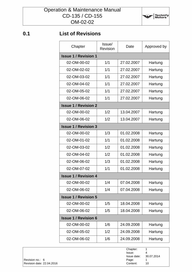
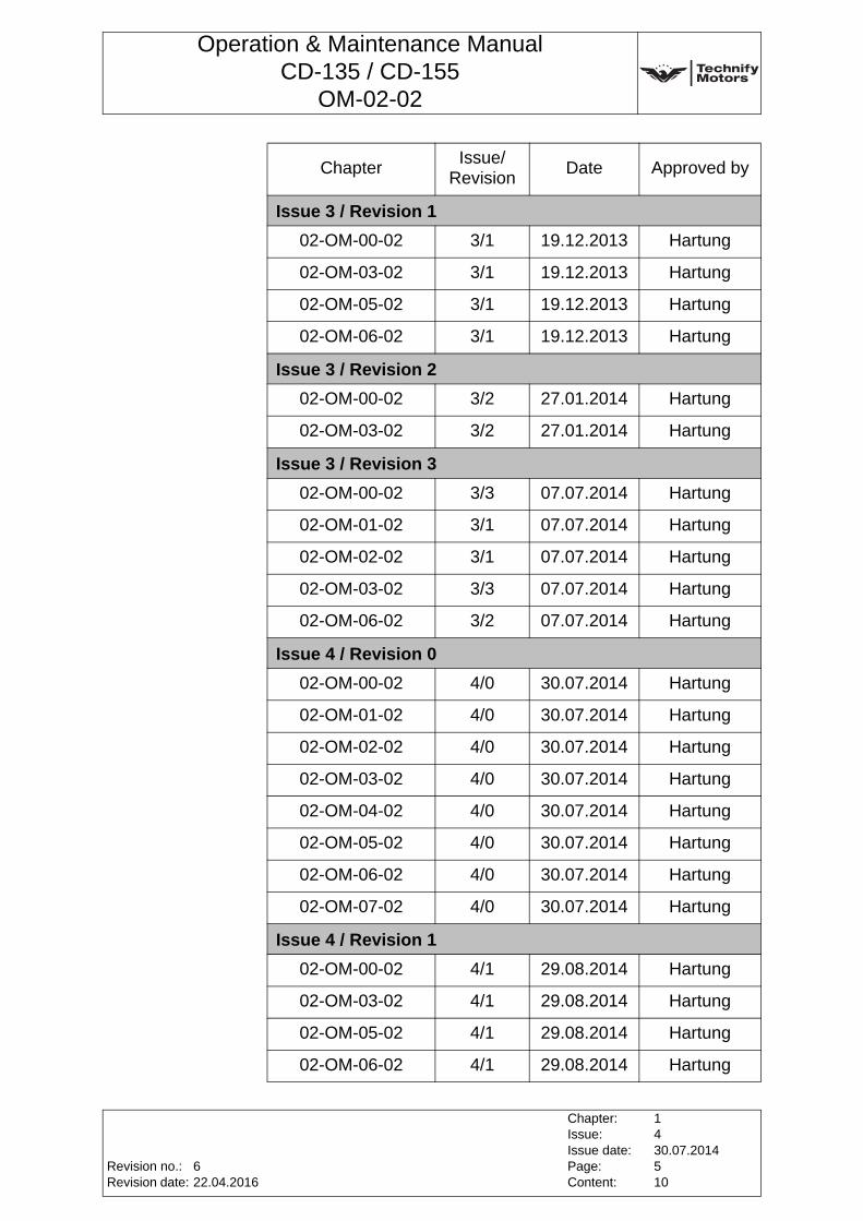
0.1 List of Revisions
ChapterIssue/
RevisionDate Approved by
Issue 1 / Revision 1
02-OM-00-02 1/1 27.02.2007 Hartung
02-OM-02-02 1/1 27.02.2007 Hartung
02-OM-03-02 1/1 27.02.2007 Hartung
02-OM-04-02 1/1 27.02.2007 Hartung
02-OM-05-02 1/1 27.02.2007 Hartung
02-OM-06-02 1/1 27.02.2007 Hartung
Issue 1 / Revision 2
02-OM-00-02 1/2 13.04.2007 Hartung
02-OM-06-02 1/2 13.04.2007 Hartung
Issue 1 / Revision 3
02-OM-00-02 1/3 01.02.2008 Hartung
02-OM-01-02 1/1 01.02.2008 Hartung
02-OM-03-02 1/2 01.02.2008 Hartung
02-OM-04-02 1/2 01.02.2008 Hartung
02-OM-06-02 1/3 01.02.2008 Hartung
02-OM-07-02 1/1 01.02.2008 Hartung
Issue 1 / Revision 4
02-OM-00-02 1/4 07.04.2008 Hartung
02-OM-06-02 1/4 07.04.2008 Hartung
Issue 1 / Revision 5
02-OM-00-02 1/5 18.04.2008 Hartung
02-OM-06-02 1/5 18.04.2008 Hartung
Issue 1 / Revision 6
02-OM-00-02 1/6 24.09.2008 Hartung
02-OM-05-02 1/2 24.09.2008 Hartung
02-OM-06-02 1/6 24.09.2008 Hartung
Revision no.:Revision date:
Chapter:Issue:Issue date:Page:Content:
1430.07.2014110
622.04.2016
Operation & Maintenance ManualCD-135 / CD-155
OM-02-02
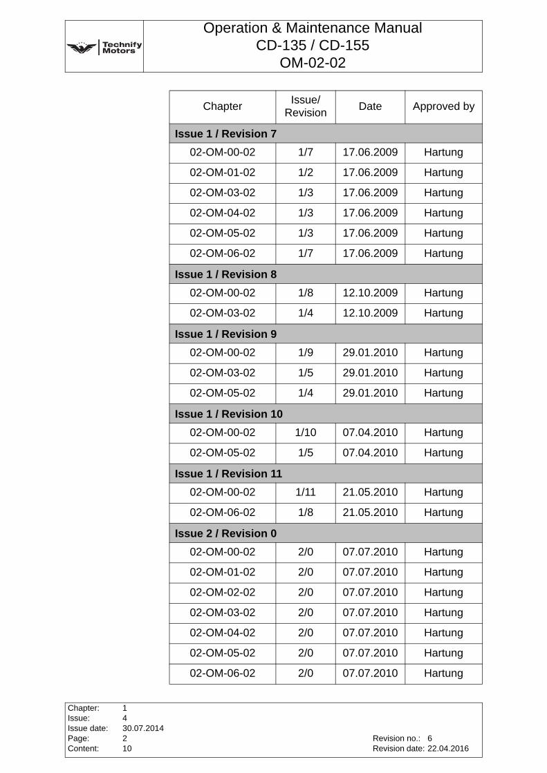
Issue 1 / Revision 7
02-OM-00-02 1/7 17.06.2009 Hartung
02-OM-01-02 1/2 17.06.2009 Hartung
02-OM-03-02 1/3 17.06.2009 Hartung
02-OM-04-02 1/3 17.06.2009 Hartung
02-OM-05-02 1/3 17.06.2009 Hartung
02-OM-06-02 1/7 17.06.2009 Hartung
Issue 1 / Revision 8
02-OM-00-02 1/8 12.10.2009 Hartung
02-OM-03-02 1/4 12.10.2009 Hartung
Issue 1 / Revision 9
02-OM-00-02 1/9 29.01.2010 Hartung
02-OM-03-02 1/5 29.01.2010 Hartung
02-OM-05-02 1/4 29.01.2010 Hartung
Issue 1 / Revision 10
02-OM-00-02 1/10 07.04.2010 Hartung
02-OM-05-02 1/5 07.04.2010 Hartung
Issue 1 / Revision 11
02-OM-00-02 1/11 21.05.2010 Hartung
02-OM-06-02 1/8 21.05.2010 Hartung
Issue 2 / Revision 0
02-OM-00-02 2/0 07.07.2010 Hartung
02-OM-01-02 2/0 07.07.2010 Hartung
02-OM-02-02 2/0 07.07.2010 Hartung
02-OM-03-02 2/0 07.07.2010 Hartung
02-OM-04-02 2/0 07.07.2010 Hartung
02-OM-05-02 2/0 07.07.2010 Hartung
02-OM-06-02 2/0 07.07.2010 Hartung
ChapterIssue/
RevisionDate Approved by
Chapter:Issue:Issue date:Page:Content:
1430.07.2014210
Revision no.:Revision date:
622.04.2016
Operation & Maintenance ManualCD-135 / CD-155
OM-02-02
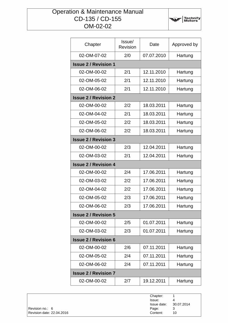
02-OM-07-02 2/0 07.07.2010 Hartung
Issue 2 / Revision 1
02-OM-00-02 2/1 12.11.2010 Hartung
02-OM-05-02 2/1 12.11.2010 Hartung
02-OM-06-02 2/1 12.11.2010 Hartung
Issue 2 / Revision 2
02-OM-00-02 2/2 18.03.2011 Hartung
02-OM-04-02 2/1 18.03.2011 Hartung
02-OM-05-02 2/2 18.03.2011 Hartung
02-OM-06-02 2/2 18.03.2011 Hartung
Issue 2 / Revision 3
02-OM-00-02 2/3 12.04.2011 Hartung
02-OM-03-02 2/1 12.04.2011 Hartung
Issue 2 / Revision 4
02-OM-00-02 2/4 17.06.2011 Hartung
02-OM-03-02 2/2 17.06.2011 Hartung
02-OM-04-02 2/2 17.06.2011 Hartung
02-OM-05-02 2/3 17.06.2011 Hartung
02-OM-06-02 2/3 17.06.2011 Hartung
Issue 2 / Revision 5
02-OM-00-02 2/5 01.07.2011 Hartung
02-OM-03-02 2/3 01.07.2011 Hartung
Issue 2 / Revision 6
02-OM-00-02 2/6 07.11.2011 Hartung
02-OM-05-02 2/4 07.11.2011 Hartung
02-OM-06-02 2/4 07.11.2011 Hartung
Issue 2 / Revision 7
02-OM-00-02 2/7 19.12.2011 Hartung
ChapterIssue/
RevisionDate Approved by
Revision no.:Revision date:
Chapter:Issue:Issue date:Page:Content:
1430.07.2014310
622.04.2016
Operation & Maintenance ManualCD-135 / CD-155
OM-02-02
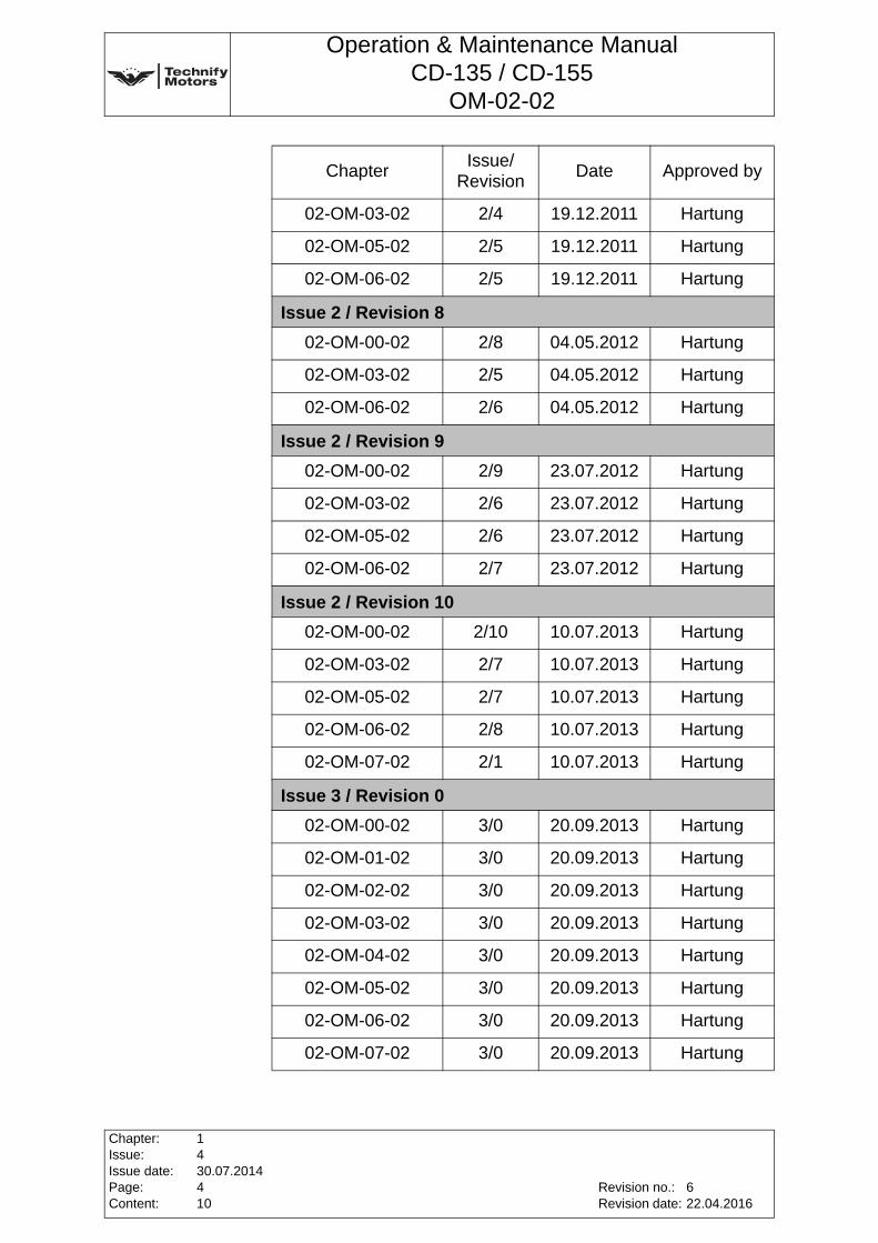
02-OM-03-02 2/4 19.12.2011 Hartung
02-OM-05-02 2/5 19.12.2011 Hartung
02-OM-06-02 2/5 19.12.2011 Hartung
Issue 2 / Revision 8
02-OM-00-02 2/8 04.05.2012 Hartung
02-OM-03-02 2/5 04.05.2012 Hartung
02-OM-06-02 2/6 04.05.2012 Hartung
Issue 2 / Revision 9
02-OM-00-02 2/9 23.07.2012 Hartung
02-OM-03-02 2/6 23.07.2012 Hartung
02-OM-05-02 2/6 23.07.2012 Hartung
02-OM-06-02 2/7 23.07.2012 Hartung
Issue 2 / Revision 10
02-OM-00-02 2/10 10.07.2013 Hartung
02-OM-03-02 2/7 10.07.2013 Hartung
02-OM-05-02 2/7 10.07.2013 Hartung
02-OM-06-02 2/8 10.07.2013 Hartung
02-OM-07-02 2/1 10.07.2013 Hartung
Issue 3 / Revision 0
02-OM-00-02 3/0 20.09.2013 Hartung
02-OM-01-02 3/0 20.09.2013 Hartung
02-OM-02-02 3/0 20.09.2013 Hartung
02-OM-03-02 3/0 20.09.2013 Hartung
02-OM-04-02 3/0 20.09.2013 Hartung
02-OM-05-02 3/0 20.09.2013 Hartung
02-OM-06-02 3/0 20.09.2013 Hartung
02-OM-07-02 3/0 20.09.2013 Hartung
ChapterIssue/
RevisionDate Approved by
Chapter:Issue:Issue date:Page:Content:
1430.07.2014410
Revision no.:Revision date:
622.04.2016
Operation & Maintenance ManualCD-135 / CD-155
OM-02-02
Issue 3 / Revision 1
02-OM-00-02 3/1 19.12.2013 Hartung
02-OM-03-02 3/1 19.12.2013 Hartung
02-OM-05-02 3/1 19.12.2013 Hartung
02-OM-06-02 3/1 19.12.2013 Hartung
Issue 3 / Revision 2
02-OM-00-02 3/2 27.01.2014 Hartung
02-OM-03-02 3/2 27.01.2014 Hartung
Issue 3 / Revision 3
02-OM-00-02 3/3 07.07.2014 Hartung
02-OM-01-02 3/1 07.07.2014 Hartung
02-OM-02-02 3/1 07.07.2014 Hartung
02-OM-03-02 3/3 07.07.2014 Hartung
02-OM-06-02 3/2 07.07.2014 Hartung
Issue 4 / Revision 0
02-OM-00-02 4/0 30.07.2014 Hartung
02-OM-01-02 4/0 30.07.2014 Hartung
02-OM-02-02 4/0 30.07.2014 Hartung
02-OM-03-02 4/0 30.07.2014 Hartung
02-OM-04-02 4/0 30.07.2014 Hartung
02-OM-05-02 4/0 30.07.2014 Hartung
02-OM-06-02 4/0 30.07.2014 Hartung
02-OM-07-02 4/0 30.07.2014 Hartung
Issue 4 / Revision 1
02-OM-00-02 4/1 29.08.2014 Hartung
02-OM-03-02 4/1 29.08.2014 Hartung
02-OM-05-02 4/1 29.08.2014 Hartung
02-OM-06-02 4/1 29.08.2014 Hartung
ChapterIssue/
RevisionDate Approved by
Revision no.:Revision date:
Chapter:Issue:Issue date:Page:Content:
1430.07.2014510
622.04.2016
Operation & Maintenance ManualCD-135 / CD-155
OM-02-02
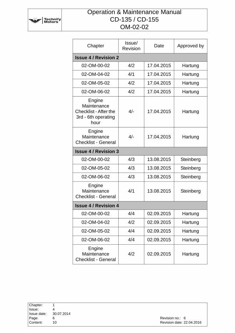
Issue 4 / Revision 2
02-OM-00-02 4/2 17.04.2015 Hartung
02-OM-04-02 4/1 17.04.2015 Hartung
02-OM-05-02 4/2 17.04.2015 Hartung
02-OM-06-02 4/2 17.04.2015 Hartung
Engine Maintenance
Checklist - After the 3rd - 6th operating
hour
4/- 17.04.2015 Hartung
Engine Maintenance
Checklist - General4/- 17.04.2015 Hartung
Issue 4 / Revision 3
02-OM-00-02 4/3 13.08.2015 Steinberg
02-OM-05-02 4/3 13.08.2015 Steinberg
02-OM-06-02 4/3 13.08.2015 Steinberg
Engine Maintenance
Checklist - General4/1 13.08.2015 Steinberg
Issue 4 / Revision 4
02-OM-00-02 4/4 02.09.2015 Hartung
02-OM-04-02 4/2 02.09.2015 Hartung
02-OM-05-02 4/4 02.09.2015 Hartung
02-OM-06-02 4/4 02.09.2015 Hartung
Engine Maintenance
Checklist - General4/2 02.09.2015 Hartung
ChapterIssue/
RevisionDate Approved by
Chapter:Issue:Issue date:Page:Content:
1430.07.2014610
Revision no.:Revision date:
622.04.2016
Operation & Maintenance ManualCD-135 / CD-155
OM-02-02
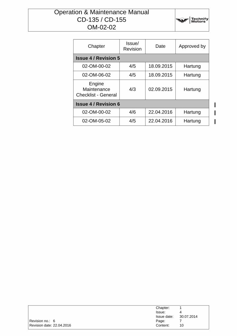
Issue 4 / Revision 5
02-OM-00-02 4/5 18.09.2015 Hartung
02-OM-06-02 4/5 18.09.2015 Hartung
Engine Maintenance
Checklist - General4/3 02.09.2015 Hartung
Issue 4 / Revision 6
02-OM-00-02 4/6 22.04.2016 Hartung
02-OM-05-02 4/5 22.04.2016 Hartung
ChapterIssue/
RevisionDate Approved by
Revision no.:Revision date:
Chapter:Issue:Issue date:Page:Content:
1430.07.2014710
622.04.2016
Operation & Maintenance ManualCD-135 / CD-155
OM-02-02
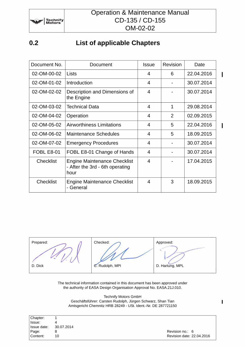
0.2 List of applicable Chapters
signatures
Document No. Document Issue Revision Date
02-OM-00-02 Lists 4 6 22.04.2016
02-OM-01-02 Introduction 4 - 30.07.2014
02-OM-02-02 Description and Dimensions of the Engine
4 - 30.07.2014
02-OM-03-02 Technical Data 4 1 29.08.2014
02-OM-04-02 Operation 4 2 02.09.2015
02-OM-05-02 Airworthiness Limitations 4 5 22.04.2016
02-OM-06-02 Maintenance Schedules 4 5 18.09.2015
02-OM-07-02 Emergency Procedures 4 - 30.07.2014
FOBL E8-01 FOBL E8-01 Change of Hands 4 - 30.07.2014
Checklist Engine Maintenance Checklist - After the 3rd - 6th operating hour
4 - 17.04.2015
Checklist Engine Maintenance Checklist - General
4 3 18.09.2015
Prepared: Checked: Approved:
D. Dick C. Rudolph, MPI D. Hartung, MPL
The technical information contained in this document has been approved under the authority of EASA Design Organisation Approval No. EASA.21J.010.
Technify Motors GmbHGeschäftsführer: Carsten Rudolph, Jürgen Schwarz, Shan Tian
Amtsgericht Chemnitz HRB 28249 - USt. Ident.-Nr. DE 287721150
Chapter:Issue:Issue date:Page:Content:
1430.07.2014810
Revision no.:Revision date:
622.04.2016
Operation & Maintenance ManualCD-135 / CD-155
OM-02-02
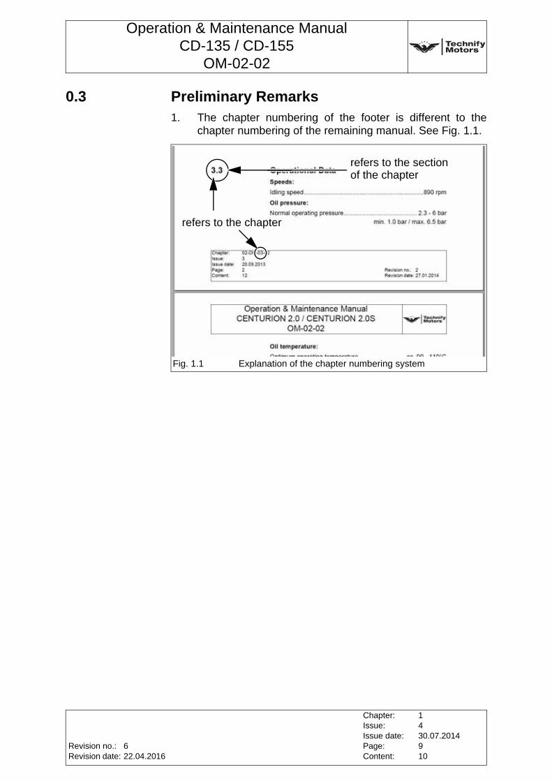
0.3 Preliminary Remarks1. The chapter numbering of the footer is different to the
chapter numbering of the remaining manual. See Fig. 1.1.
Fig. 1.1 Explanation of the chapter numbering system
refers to the chapter
refers to the sectionof the chapter
Revision no.:Revision date:
Chapter:Issue:Issue date:Page:Content:
1430.07.2014910
622.04.2016

Operation & Maintenance ManualCD-135 / CD-155
OM-02-02
This page intentionally left blank
Chapter:Issue:Issue date:Page:Content:
1430.07.20141010
Revision no.:Revision date:
622.04.2016
Operation & Maintenance ManualCD-135 / CD-155
OM-02-02
1 IntroductionThis Operation and Maintenance Manual contains basic information related to the proper operation of the engine in various situations and under different conditions. It also contains instructions for maintenance. The information and descriptions of components and systems in this manual were correct at the time of publication. Any amendments released through the update information service must be taken into account. Please contact Technify Motors GmbH if you have any questions. We will be glad to provide further assistance.
Contact address: Technify Motors GmbHPlatanenstr. 1409356 Sankt Egidien, GERMANYFon: +49 37204 696-0Fax: +49 37204 696-2912
1.1 Accompanying applicable Document
Manual Title Doc. No.
Installation Manual IM-02-02
Repair Manual RM-02-02
Illustrated Parts Catalogue IPC-02-02
Aircraft Manufacturers Manual ---
Note: The current version of the manuals are announced in the Service Bulletin TM TAE 000-0004.
Revision no.:Revision date:
Chapter:Issue:Issue date:Page:Content:
02-OM-01-02430.07.201418
--
Operation & Maintenance ManualCD-135 / CD-155
OM-02-02
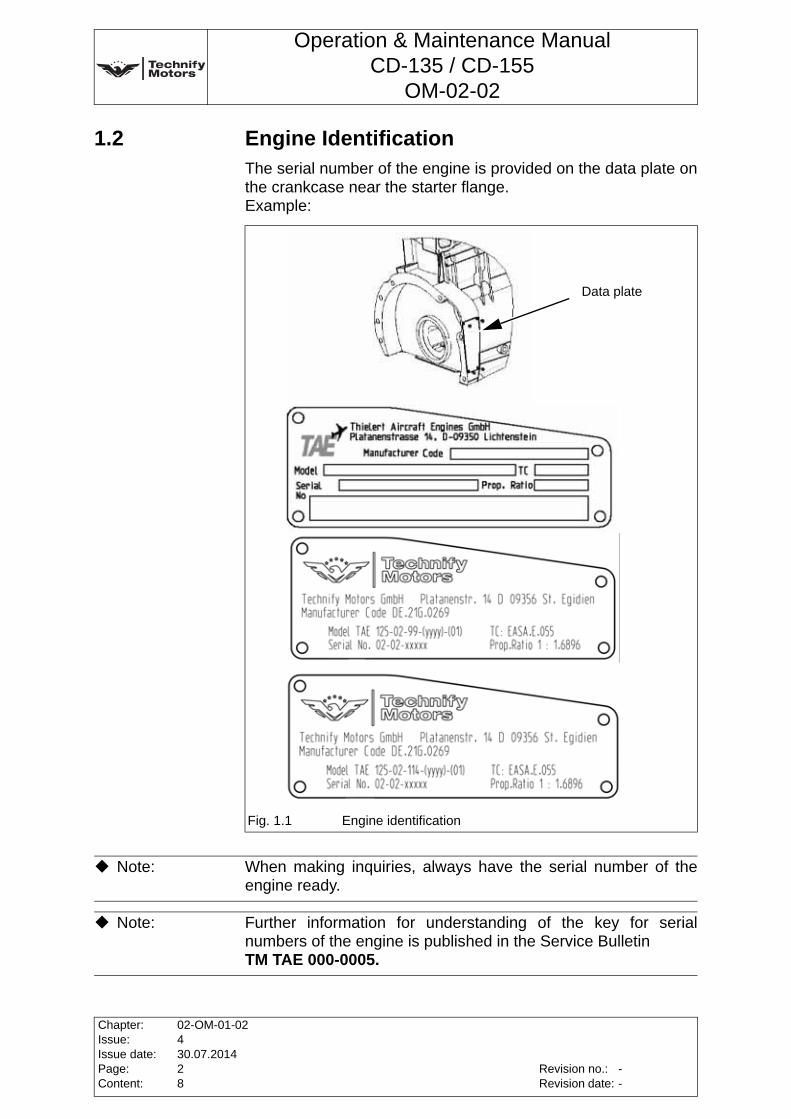
1.2 Engine IdentificationThe serial number of the engine is provided on the data plate on the crankcase near the starter flange. Example:
Fig. 1.1 Engine identification
Data plate
Note: When making inquiries, always have the serial number of the engine ready.
Note: Further information for understanding of the key for serial numbers of the engine is published in the Service Bulletin TM TAE 000-0005.
Chapter:Issue:Issue date:Page:Content:
02-OM-01-02430.07.201428
Revision no.:Revision date:
--
Operation & Maintenance ManualCD-135 / CD-155
OM-02-02
1.3 Copyright ©
1.4 Safety RecommendationsThe following symbols and warning signs are used in the manual. They must be heeded strictly to prevent personal injury and material damage, to avoid impairment of the operational safety of the aircraft and to rule out any damage to the aircraft as a consequence of improper handling
The indications "right", "left", "front" and "rear" are always given in relation to the flight direction. The following symbol is used:
Example of flight direction to the right:
1.5 Validity of this ManualUpdates and modifications must be taken into account.Effective manuals are announced in the Service BulletinTM TAE 000-0004.
1.6 AbbreviationsThe following abbreviations are used in this manual:
• FADEC - Full Authority Digital Engine Control
This manual, the technical data and the information contained therein are the property of Technify Motors GmbH and may not
be reproduced either in full or in part or passed on to a third party without written consent from
Technify Motors GmbH. This text must be included in any full or partial reproduction of
this documentation.Copyright © Technify Motors GmbH
WARNING: Disregarding these safety rules can cause personal injury or even death.
CAUTION: Disregarding these special instructions and safety measures can cause damage to the engine or to other components.
Note: Additional note or instructions for better understanding of an instruction.
Revision no.:Revision date:
Chapter:Issue:Issue date:Page:Content:
02-OM-01-02430.07.201438
--
Operation & Maintenance ManualCD-135 / CD-155
OM-02-02
1.7 Packaging and TransportThe engine has been packaged at the factory for transport as follows:
• Mounted on a support in a wooden crate
• Supplied with drying agent
• When the engine is transported by ship, it is packed seaworthy
The packaging should be kept for re-use in a possible future shipment.
1.8 StorageThe following must be observed during transport and subsequent storage:
• Store only in workplaces that are suitable for the purpose
• Never store outside
• Ambient temperature: -25°C to +70°C
• Rel. humidity: less than 70%
• The shipping crate must be kept in a horizontal position during storage
• The max. storage time is noted on the delivery note of the engine
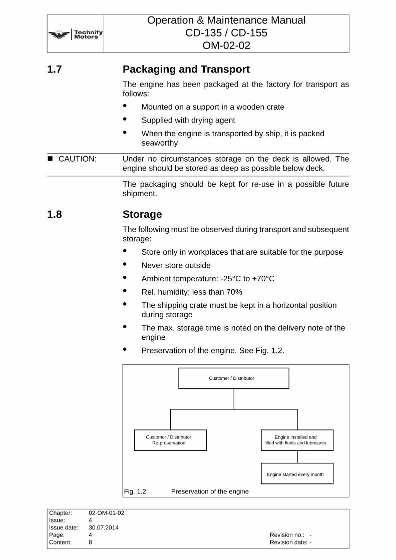
• Preservation of the engine. See Fig. 1.2.
CAUTION: Under no circumstances storage on the deck is allowed. The engine should be stored as deep as possible below deck.
Fig. 1.2 Preservation of the engine
Customer / Distributor
Customer / DistributorRe-preservation
Engine installed andfilled with fluids and lubricants
Engine started every month
Chapter:Issue:Issue date:Page:Content:
02-OM-01-02430.07.201448
Revision no.:Revision date:
--
Operation & Maintenance ManualCD-135 / CD-155
OM-02-02
1.9 Scope of SupplyThe scope of supply is specified inChapter 2, Section 2.2, Page 1 of this Manual.
1.10 Qualifications of the Operating and Maintenance PersonnelThe organizations who carry out work on the engine must be authorized by Technify Motors GmbH. All tasks and checks described in this manual must only be performed by trained personnel who have the necessary licenses and a valid training certificate issued by Technify Motors GmbH. Further information about Technify Motors GmbH authorized organizations can be found in the Service BulletinTM TAE 000-0003. All applicable national and international regulations must be observed.
1.11 Update Information ServiceThis manual is covered by a continuous update information service. The engine / aircraft operator is responsible for keeping up-to-date with all amendment bulletins issued by Technify Motors GmbH and integrating them into this manual. Please inform Technify Motors GmbH if the owner of the engine / aircraft changes. This is the only way to ensure that information about any necessary / recommended changes to the engine / handbook can be passed on. A form is included for this purpose in this manual. See FOBL E8-01 - Change of Hands.
1.12 Service Life of this Engine
WARNING: The service life of the engine is limited. Technify Motors GmbH therefore most strongly recommends that the engine should be replaced when it reaches the end of the operating period recommended in the relevant current version of the Service BulletinTM TAE 125-0001.
Revision no.:Revision date:
Chapter:Issue:Issue date:Page:Content:
02-OM-01-02430.07.201458
--
Operation & Maintenance ManualCD-135 / CD-155
OM-02-02
1.13 Safety Information
• This engine is not suitable for aerobatic use.
• This engine is not approved for rotorcraft (helicopters, gyrocopters, etc.).
• Never leave the aircraft unattended while the engine is running.
• Secure all tools before starting the engine to prevent personal injury or damage.
• When the engine is not in use, protect it and the fuel system from contamination and accidental / unauthorized manipulation.
• Never operate the engine without the specified quality and quantity of fluids.
• Engine monitoring instruments are not included in the scope of supply of the engine. Only use suitable, approved instruments.
• In some areas, at some flight altitudes and under certain operating conditions, it may be necessary to protect the engine from extreme humidity, dust or sand using further special equipment. Please consult the aircraft manufacturer or distributor.
• Under extreme conditions such as low usage combined with operation in a oceanic atmosphere, or in a very dusty or sandy environment, shorter maintenance and inspection intervals are recommended for your own safety.
• The Technify Motors GmbH engine must only be taken into operation by persons who are familiar with the corresponding manuals and who have the required level of authorization.
WARNING: Any Aircraft Engine Ground Run must be conducted in a secure area that is protected from the unauthorized movement of personnel!Any rotating propeller is a potential safety hazard that can cause severe personal injuries or even death!
Note: Technify Motors GmbH offers an engine displayP/N 02-7730-5501-()-() suitable to monitor all necessary engine parameters.This display is approved in accordance with JTSO-C113.
Chapter:Issue:Issue date:Page:Content:
02-OM-01-02430.07.201468
Revision no.:Revision date:
--
Operation & Maintenance ManualCD-135 / CD-155
OM-02-02
• Only the approved equipment must be used. The use of any unapproved equipment absolves the manufacturer from any liability.
• Improper installation, the use of non-suitable lines for the fuel, cooling and oil circuits, and operation with non-approved fuels or lubricants/oils absolves the manufacturer from any liability.
• Any unauthorized modifications made to the engine or the aircraft absolve the manufacturer from liability for related damages.
• The pertinent accident prevention regulations as well as other commonly accepted safety, occupational health and air traffic legal requirements must also be observed.
• Operators must also observe any additional regulations and requirements which are applicable in their territory.
Revision no.:Revision date:
Chapter:Issue:Issue date:Page:Content:
02-OM-01-02430.07.201478
--

Operation & Maintenance ManualCD-135 / CD-155
OM-02-02
This page intentionally left blank
Chapter:Issue:Issue date:Page:Content:
02-OM-01-02430.07.201488
Revision no.:Revision date:
--

Operation & Maintenance ManualCD-135 / CD-155
OM-02-02
2 Description and Dimensions of the Engine
2.1 Engine DesignationCD-135 (TAE 125-02-99)CD-155 (TAE 125-02-114)
2.2 Description and Standard Production VersionThe Continental Diesel CD-135 / CD-155 is a liquid-cooled 4-cylinder in-line four-stroke diesel engine with DOHC (double overhead camshaft). The valves are activated by cam followers. The operation of the direct diesel-injection engine is based on the common-rail technique and is turbo charged. The engine is controlled by a FADEC system. The propeller is driven via an integrated gearbox (i=1.69) with a clutch or dual mass flywheel. The engine is equipped with an electric starter and an alternator.
Scope of Supply The following components and assemblies are included in the scope of supply of the CD-135 / CD-155:
• Turbocharger
• Integrated propeller controlling and adjusting unit
• Alternator
• Starter
• FADEC system
• Wiring harness
• all of the actuators and sensor required for engine operation
• Vacuum pump
• Water pump
• Engine shock mounts
• Injection system
• Fuel feed pump and high-pressure fuel pump
• Oil pump
• Gearbox
Revision no.:Revision date:
Chapter:Issue:Issue date:Page:Content:
02-OM-02-02430.07.201414
--
Operation & Maintenance ManualCD-135 / CD-155
OM-02-02
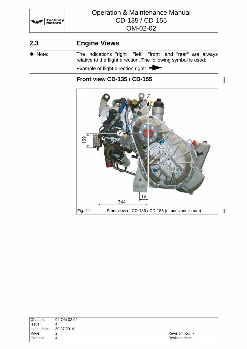
2.3 Engine Views
Front view CD-135 / CD-155
Note: The indications "right", "left", "front" and "rear" are always relative to the flight direction. The following symbol is used:
Example of flight direction right:
Fig. 2.1 Front view of CD-135 / CD-155 (dimensions in mm)
Chapter:Issue:Issue date:Page:Content:
02-OM-02-02430.07.201424
Revision no.:Revision date:
--
Operation & Maintenance ManualCD-135 / CD-155
OM-02-02
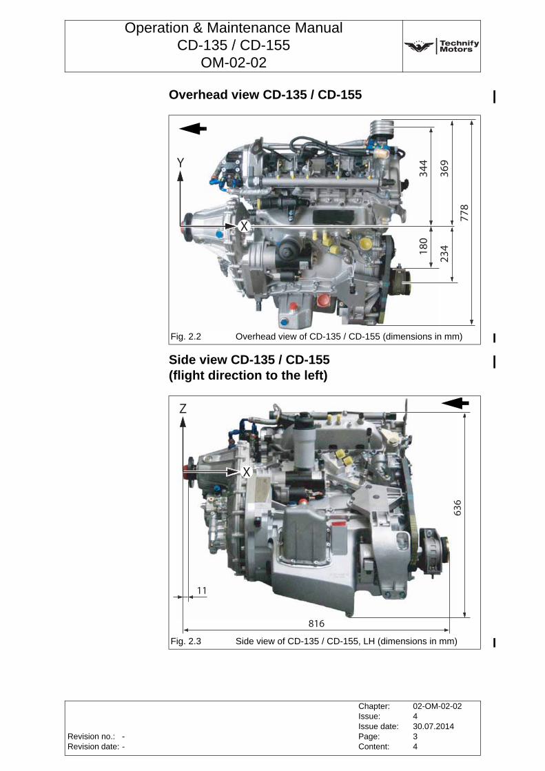
Overhead view CD-135 / CD-155
Side view CD-135 / CD-155 (flight direction to the left)
Fig. 2.2 Overhead view of CD-135 / CD-155 (dimensions in mm)
Fig. 2.3 Side view of CD-135 / CD-155, LH (dimensions in mm)
Revision no.:Revision date:
Chapter:Issue:Issue date:Page:Content:
02-OM-02-02430.07.201434
--
Operation & Maintenance ManualCD-135 / CD-155
OM-02-02
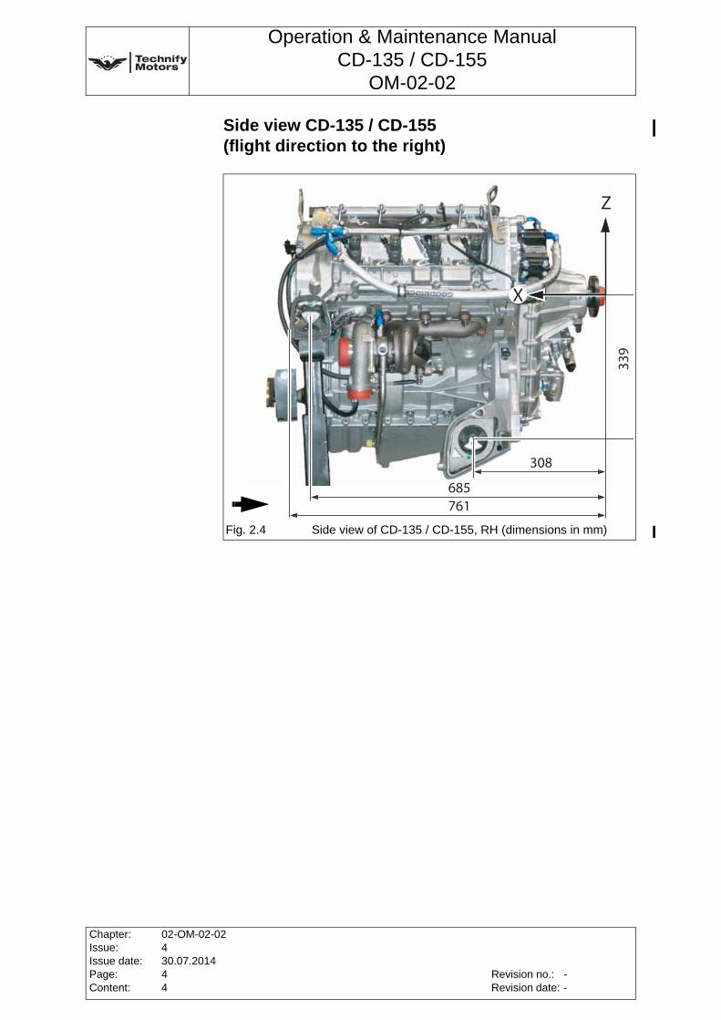
Side view CD-135 / CD-155(flight direction to the right)
Fig. 2.4 Side view of CD-135 / CD-155, RH (dimensions in mm)
Chapter:Issue:Issue date:Page:Content:
02-OM-02-02430.07.201444
Revision no.:Revision date:
--
Operation & Maintenance ManualCD-135 / CD-155
OM-02-02
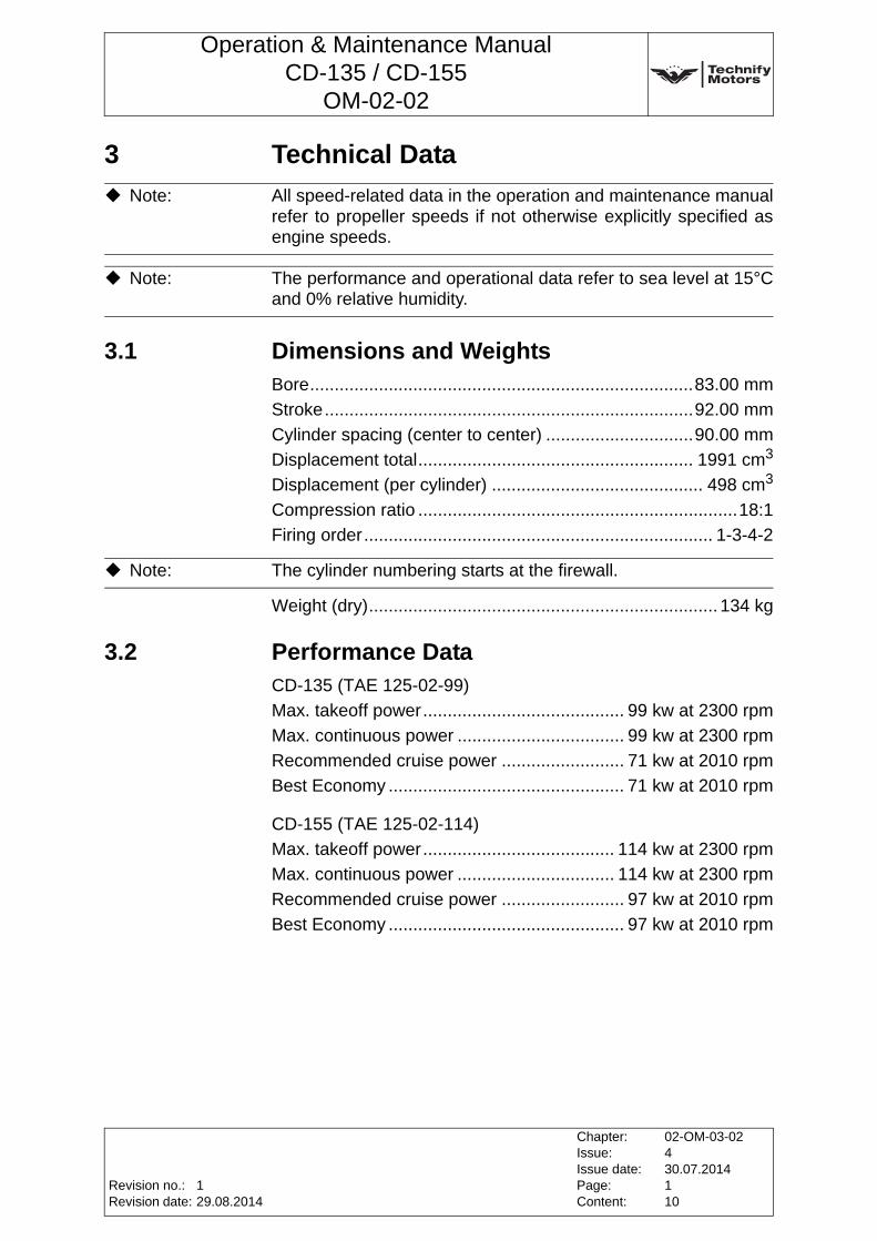
3 Technical Data
3.1 Dimensions and WeightsBore..............................................................................83.00 mm
Stroke...........................................................................92.00 mm
Cylinder spacing (center to center) ..............................90.00 mm
Displacement total........................................................ 1991 cm3
Displacement (per cylinder) ........................................... 498 cm3
Compression ratio .................................................................18:1
Firing order....................................................................... 1-3-4-2
Weight (dry)....................................................................... 134 kg
3.2 Performance DataCD-135 (TAE 125-02-99)
Max. takeoff power......................................... 99 kw at 2300 rpm
Max. continuous power .................................. 99 kw at 2300 rpm
Recommended cruise power ......................... 71 kw at 2010 rpm
Best Economy ................................................ 71 kw at 2010 rpm
CD-155 (TAE 125-02-114)
Max. takeoff power....................................... 114 kw at 2300 rpm
Max. continuous power ................................ 114 kw at 2300 rpm
Recommended cruise power ......................... 97 kw at 2010 rpm
Best Economy ................................................ 97 kw at 2010 rpm
Note: All speed-related data in the operation and maintenance manual refer to propeller speeds if not otherwise explicitly specified as engine speeds.
Note: The performance and operational data refer to sea level at 15°C and 0% relative humidity.
Note: The cylinder numbering starts at the firewall.
Revision no.:Revision date:
Chapter:Issue:Issue date:Page:Content:
02-OM-03-02430.07.2014110
129.08.2014
Operation & Maintenance ManualCD-135 / CD-155
OM-02-02
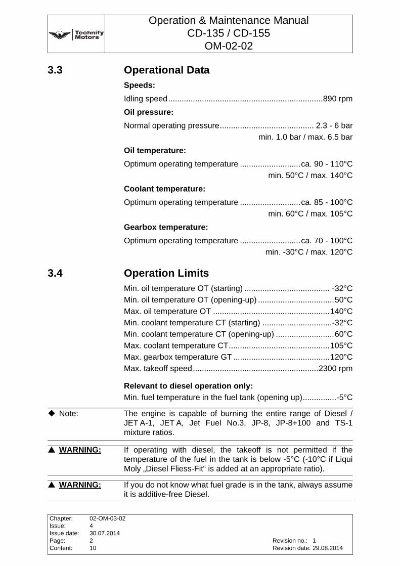
3.3 Operational DataSpeeds:
Idling speed.....................................................................890 rpm
Oil pressure:
Normal operating pressure.......................................... 2.3 - 6 bar
min. 1.0 bar / max. 6.5 bar
Oil temperature:
Optimum operating temperature ...........................ca. 90 - 110°C
min. 50°C / max. 140°C
Coolant temperature:
Optimum operating temperature ...........................ca. 85 - 100°C
min. 60°C / max. 105°C
Gearbox temperature:
Optimum operating temperature ...........................ca. 70 - 100°C
min. -30°C / max. 120°C
3.4 Operation LimitsMin. oil temperature OT (starting) ...................................... -32°C
Min. oil temperature OT (opening-up) ..................................50°C
Max. oil temperature OT ....................................................140°C
Min. coolant temperature CT (starting) ...............................-32°C
Min. coolant temperature CT (opening-up) ..........................60°C
Max. coolant temperature CT.............................................105°C
Max. gearbox temperature GT ...........................................120°C
Max. takeoff speed........................................................2300 rpm
Relevant to diesel operation only:
Min. fuel temperature in the fuel tank (opening up)...............-5°C
Note: The engine is capable of burning the entire range of Diesel / JET A-1, JET A, Jet Fuel No.3, JP-8, JP-8+100 and TS-1 mixture ratios.
WARNING: If operating with diesel, the takeoff is not permitted if the temperature of the fuel in the tank is below -5°C (-10°C if Liqui Moly „Diesel Fliess-Fit“ is added at an appropriate ratio).
WARNING: If you do not know what fuel grade is in the tank, always assume it is additive-free Diesel.
Chapter:Issue:Issue date:Page:Content:
02-OM-03-02430.07.2014210
Revision no.:Revision date:
129.08.2014
Operation & Maintenance ManualCD-135 / CD-155
OM-02-02
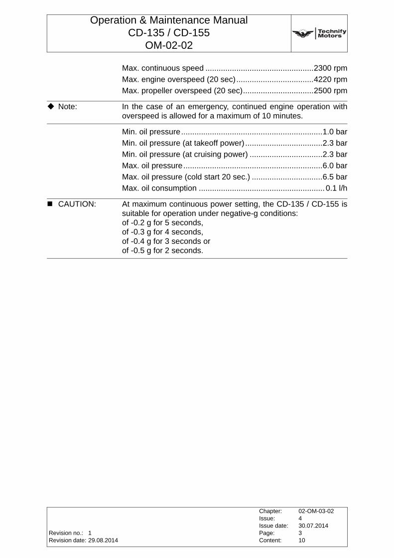
Max. continuous speed .................................................2300 rpm
Max. engine overspeed (20 sec)...................................4220 rpm
Max. propeller overspeed (20 sec)................................2500 rpm
Min. oil pressure................................................................1.0 bar
Min. oil pressure (at takeoff power) ...................................2.3 bar
Min. oil pressure (at cruising power) .................................2.3 bar
Max. oil pressure...............................................................6.0 bar
Max. oil pressure (cold start 20 sec.) ................................6.5 bar
Max. oil consumption ......................................................... 0.1 l/h
Note: In the case of an emergency, continued engine operation with overspeed is allowed for a maximum of 10 minutes.
CAUTION: At maximum continuous power setting, the CD-135 / CD-155 is suitable for operation under negative-g conditions: of -0.2 g for 5 seconds, of -0.3 g for 4 seconds, of -0.4 g for 3 seconds or of -0.5 g for 2 seconds.
Revision no.:Revision date:
Chapter:Issue:Issue date:Page:Content:
02-OM-03-02430.07.2014310
129.08.2014
Operation & Maintenance ManualCD-135 / CD-155
OM-02-02
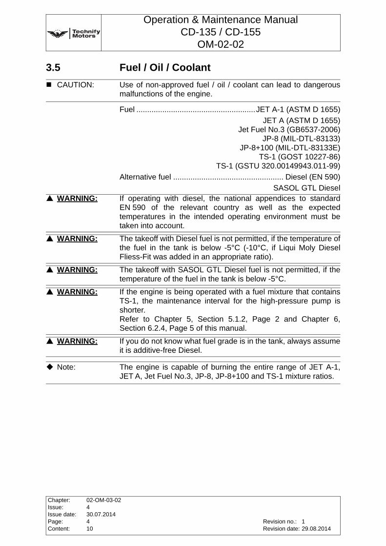
3.5 Fuel / Oil / Coolant
Fuel .......................................................JET A-1 (ASTM D 1655)
JET A (ASTM D 1655)Jet Fuel No.3 (GB6537-2006)
JP-8 (MIL-DTL-83133)JP-8+100 (MIL-DTL-83133E)
TS-1 (GOST 10227-86)TS-1 (GSTU 320.00149943.011-99)
Alternative fuel ................................................... Diesel (EN 590)
SASOL GTL Diesel
CAUTION: Use of non-approved fuel / oil / coolant can lead to dangerous malfunctions of the engine.
WARNING: If operating with diesel, the national appendices to standard EN 590 of the relevant country as well as the expected temperatures in the intended operating environment must be taken into account.
WARNING: The takeoff with Diesel fuel is not permitted, if the temperature of the fuel in the tank is below -5°C (-10°C, if Liqui Moly Diesel Fliess-Fit was added in an appropriate ratio).
WARNING: The takeoff with SASOL GTL Diesel fuel is not permitted, if the temperature of the fuel in the tank is below -5°C.
WARNING: If the engine is being operated with a fuel mixture that contains TS-1, the maintenance interval for the high-pressure pump is shorter.Refer to Chapter 5, Section 5.1.2, Page 2 and Chapter 6, Section 6.2.4, Page 5 of this manual.
WARNING: If you do not know what fuel grade is in the tank, always assume it is additive-free Diesel.
Note: The engine is capable of burning the entire range of JET A-1, JET A, Jet Fuel No.3, JP-8, JP-8+100 and TS-1 mixture ratios.
Chapter:Issue:Issue date:Page:Content:
02-OM-03-02430.07.2014410
Revision no.:Revision date:
129.08.2014
Operation & Maintenance ManualCD-135 / CD-155
OM-02-02
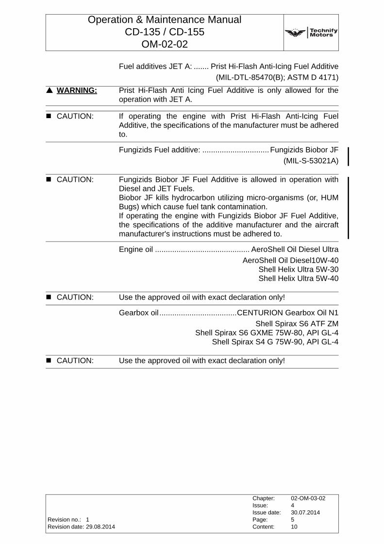
Fuel additives JET A: ....... Prist Hi-Flash Anti-Icing Fuel Additive
(MIL-DTL-85470(B); ASTM D 4171)
Fungizids Fuel additive: ...............................Fungizids Biobor JF
(MIL-S-53021A)
Engine oil ............................................ AeroShell Oil Diesel Ultra
AeroShell Oil Diesel10W-40Shell Helix Ultra 5W-30Shell Helix Ultra 5W-40
Gearbox oil ....................................CENTURION Gearbox Oil N1
Shell Spirax S6 ATF ZMShell Spirax S6 GXME 75W-80, API GL-4
Shell Spirax S4 G 75W-90, API GL-4
WARNING: Prist Hi-Flash Anti Icing Fuel Additive is only allowed for the operation with JET A.
CAUTION: If operating the engine with Prist Hi-Flash Anti-Icing Fuel Additive, the specifications of the manufacturer must be adhered to.
CAUTION: Fungizids Biobor JF Fuel Additive is allowed in operation with Diesel and JET Fuels.Biobor JF kills hydrocarbon utilizing micro-organisms (or, HUM Bugs) which cause fuel tank contamination.If operating the engine with Fungizids Biobor JF Fuel Additive, the specifications of the additive manufacturer and the aircraft manufacturer's instructions must be adhered to.
CAUTION: Use the approved oil with exact declaration only!
CAUTION: Use the approved oil with exact declaration only!
Revision no.:Revision date:
Chapter:Issue:Issue date:Page:Content:
02-OM-03-02430.07.2014510
129.08.2014
Operation & Maintenance ManualCD-135 / CD-155
OM-02-02
Coolant.................. Water / radiator protection in a ratio of 50:50
Radiator protection............... BASF Glysantin Protect Plus / G48
Valvoline / Zerex Glysantin G48BASF Glysantin Alu Protect / G30
Valvoline / Zerex Glysantin G30BASF Glysantin Protect / G05
Valvoline / Zerex Glysantin G05Mobil Antifreeze Extra (G48)
Comma Xstream Green - Concentrate (G48)
WARNING: No coolant loss may occur during operation! Any coolant loss must immediately be followed by a technical inspection which has to be carried out by an authorized person. Engine damage could result from coolant loss, and this could cause engine failure.
WARNING: If the ice flocculation point of the coolant is outside the specified range, the full anti-corrosion and anti-freeze protection is possibly not guaranteed.
CAUTION: Glysantin G05, Glysantin G30 and Glysantin G48 must not be mixed with each other.
CAUTION: Operation with Glysantin G30 is only permitted without silicate pouch.
CAUTION: Operation with Glysantin G05 or Glysantin G48 is only permitted with silicate pouch.
CAUTION: Exchange between the coolants Glysantin G30 and Glysantin G05 / Glysantin G48 is not permitted without an alteration of the installation. Refer to IM-02-02.
CAUTION: The water must meet the following criteria:1. Visual appearance: colorless, clear, no deposits allowed2. pH-value: 6.5 to 8.53. Water hardness: max. 2.7 mmol/l4. Hydrogen carbonate: max. 100 mg/l5. Chloride concentration: max. 100 mg/l6. Sulfate concentration: max. 100 mg/l
Note: It is recommended to use Glysantin Protect Plus Ready-Mix and Glysantin Alu Protect Ready-Mix respectively to ensure proper coolant quality.
Chapter:Issue:Issue date:Page:Content:
02-OM-03-02430.07.2014610
Revision no.:Revision date:
129.08.2014
Operation & Maintenance ManualCD-135 / CD-155
OM-02-02
Note: The ice flocculation point of the coolant is -38°C, if mixed 50:50. Glysantin G05, Glysantin G30 and Glysantin G48 are anti-corrosion and anti-freeze additives. The ice flocculation point must be -38°C +/-2°C. If the freezing point is outside this range the coolant has to be exchanged.
Note: The aircraft coolant system might have additional requirements for the coolant.
Revision no.:Revision date:
Chapter:Issue:Issue date:Page:Content:
02-OM-03-02430.07.2014710
129.08.2014
Operation & Maintenance ManualCD-135 / CD-155
OM-02-02
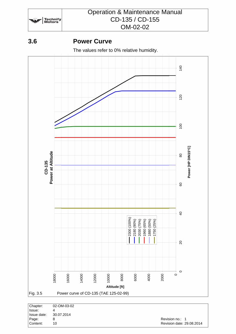
3.6 Power CurveThe values refer to 0% relative humidity.
Fig. 3.5 Power curve of CD-135 (TAE 125-02-99)
CD
-135
Pow
er a
t Alti
tude
0
2000
4000
6000
8000
1000
0
1200
0
1400
0
1600
0
1800
0
020
4060
8010
012
014
0
Pow
er [H
P D
IN15
°C]
Altitude [ft]
2300
(100
%)
2180
(90%
)20
30 (7
5%)
1960
(65%
)18
80 (5
0%)
1750
(25%
)
Chapter:Issue:Issue date:Page:Content:
02-OM-03-02430.07.2014810
Revision no.:Revision date:
129.08.2014
Operation & Maintenance ManualCD-135 / CD-155
OM-02-02
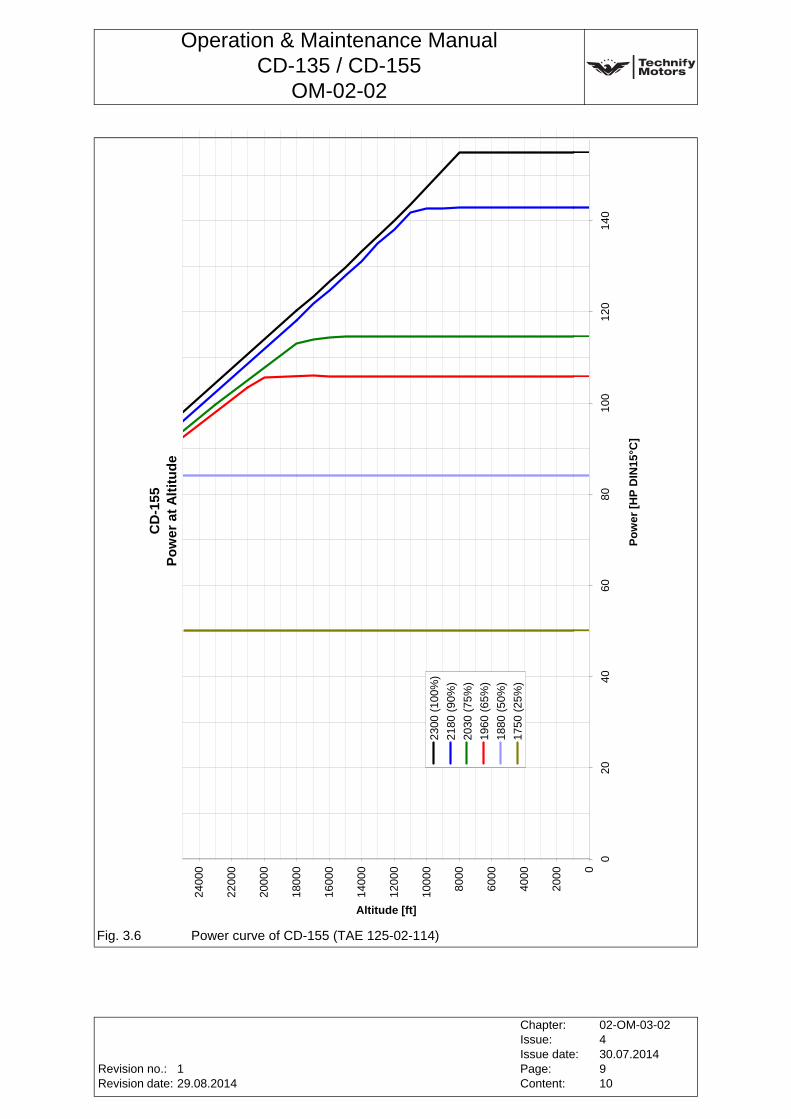
Fig. 3.6 Power curve of CD-155 (TAE 125-02-114)
CD
-155
Pow
er a
t Alti
tude
0
2000
4000
6000
8000
1000
0
1200
0
1400
0
1600
0
1800
0
2000
0
2200
0
2400
0
020
4060
8010
012
014
0
Pow
er [H
P D
IN15
°C]
Altitude [ft]
2300
(100
%)
2180
(90%
)20
30 (7
5%)
1960
(65%
)18
80 (5
0%)
1750
(25%
)
Revision no.:Revision date:
Chapter:Issue:Issue date:Page:Content:
02-OM-03-02430.07.2014910
129.08.2014
Operation & Maintenance ManualCD-135 / CD-155
OM-02-02
3.7 Low Temperature Data and Climate Classes of Diesel in Europe
Note: The officially published figures in EN 590 must be observed.
Note: The minimum opening-up fuel temperature in the tank can be lowered from -5°C to -10°C if Liqui Moly „Diesel Fliess-Fit“ is added according to the application and dose specifications of Liqui Moly.
Chapter:Issue:Issue date:Page:Content:
02-OM-03-02430.07.20141010
Revision no.:Revision date:
129.08.2014
Operation & Maintenance ManualCD-135 / CD-155
OM-02-02
4 Operation
4.1 Pre-start Inspection1. Perform "Pre-flight check" (refer to Chapter 6, Section 6.1,
Page 2 of this Manual)
2. Check fuel, oil and coolant quantities (refer to the aircraft manufacturer´s specifications)
3. Fuel shut-off valve - "OPEN"
4. Main switch for electrical system - "ON"
5. Check whether the load selector moves freely, check load indicator: at 0 speed, load must be shown as 0%. The load indicator is described in your Pilot´s Operating Handbook.
WARNING: For operation with diesel, the aircraft must not be started if the temperature of the fuel in the tank is below -5°C (-10°C if Liqui Moly „Diesel Fliess-Fit“, No.: 5130 is added according to the manufacturer’s specifications).If you do not know what fuel grade is in the tank, always assume it is additive-free Diesel.
WARNING: No coolant loss may occur during operation! Any coolant loss must immediately be followed by a technical inspection by an authorized person. Coolant loss could result in engine malfunction, which can lead to engine failure!
Note: All speed-related data in the operation and maintenance manual refer to propeller speeds unless otherwise specified explicitly as engine speeds.
WARNING: For operation with diesel, the aircraft must not be started if the temperature of the fuel in the tank is below -5°C (-10°C if Liqui Moly „Diesel Fliess-Fit“, No.: 5130 is added according to the manufacturer’s specifications).If you do not know what fuel grade is in the tank, always assume it is additive-free Diesel.
Revision no.:Revision date:
Chapter:Issue:Issue date:Page:Content:
02-OM-04-02430.07.2014110
202.09.2015
Operation & Maintenance ManualCD-135 / CD-155
OM-02-02
4.2 Start-up
1. Electric fuel pump (if available) - "ON"
2. Load selector - "IDLE"
3. Inspect the hazard zone around the aircraft / propeller.
4. Switch on the Engine Master Switch, wait until the glow plug light extinguishes, then activate the starter (max. 10 seconds). Release the key or button immediately after the engine starts and leave the load selector in the idle position.
5. Electrical fuel pump - "OFF"
6. Check the oil pressure (refer to Chapter 3, Section 3.3, Page 2 of this Manual for the values).
WARNING: Any Aircraft Engine Ground Run must be conducted in a secure area that is protected from the unauthorized movement of personnel!Any rotating propeller is a potential safety hazard that can cause severe personal injuries or even death!
CAUTION: If external power is used for start-up of a 12V Version of the CD-135 / CD-155, ensure that a 12V supply is used. If 24V has been used, contact Technify Motors GmbH.
Note: The electrical fuel pump is not included in the scope of supply of the engine; instead, it is part of the aircraft installation (refer to the aircraft manual).
CAUTION: Do not overheat the starter. Do not operate the starter for more than 10 seconds. After operating the starter, let it cool down for 20 seconds. After six attempts to start the engine, let the starter cool down for half an hour.
CAUTION: If the minimum required oil pressure of 1 bar is not indicated after 3 seconds: switch off the engine immediately.
Note: The glow plugs are supplied with power by a preheat relay before and during starting as well as after engine start. The FADEC is solely responsible for their activation.
Chapter:Issue:Issue date:Page:Content:
02-OM-04-02430.07.2014210
Revision no.:Revision date:
202.09.2015
Operation & Maintenance ManualCD-135 / CD-155
OM-02-02
4.3 Engine Warm-up• Allow the engine to warm up for approximately 2 minutes at
idle speed.
• Then increase the propeller speed to 1400 rpm until the oil temperature has reached 50°C and the coolant temperature has reached 60°C.
4.4 Before Takeoff Check
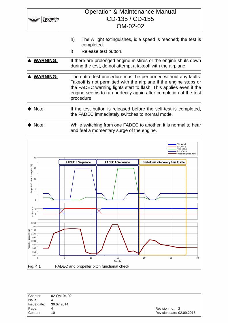
4.4.1 FADEC and propeller pitch functional check
a) Set the load selector to idle (both FADEC indicator lights should be off).
b) Press and hold the FADEC test button for the duration of the entire procedure.
c) Both FADEC A and FADEC B lights illuminate and the PROPELLER SPEED increases. (Propeller speed target 1100-1300PropRPM)
d) The system then automatically switches to the FADEC B (only the B light is on).
e) The propeller governor is activated; the propeller speed decreases.(Propeller speed target 800-900PropRPM)
f) The system automatically switches to the FADEC A (only the A light is on), the propeller speed increases. (Propeller speed target 1100-1300PropRPM)
g) The propeller governor is activated; the propeller speed decreases.(Propeller speed target 800-900PropRPM)
WARNING: For operation with diesel, the aircraft must not be started if the temperature of the fuel in the tank is below -5°C (-10°C if Liqui Moly „Diesel Fliess-Fit“, No.: 5130 is added according to the manufacturer’s specifications).If you do not know what fuel grade is in the tank, always assume it is additive-free Diesel.
Note: The engine instrumentation has to be observed during the subsequent steps.
WARNING: If the indicator lights do not illuminate at this time, a takeoff must not be attempted with the aircraft.
Revision no.:Revision date:
Chapter:Issue:Issue date:Page:Content:
02-OM-04-02430.07.2014310
202.09.2015
Operation & Maintenance ManualCD-135 / CD-155
OM-02-02
h) The A light extinguishes, idle speed is reached; the test is completed.
i) Release test button.
WARNING: If there are prolonged engine misfires or the engine shuts down during the test, do not attempt a takeoff with the airplane.
WARNING: The entire test procedure must be performed without any faults. Takeoff is not permitted with the airplane if the engine stops or the FADEC warning lights start to flash. This applies even if the engine seems to run perfectly again after completion of the test procedure.
Note: If the test button is released before the self-test is completed, the FADEC immediately switches to normal mode.
Note: While switching from one FADEC to another, it is normal to hear and feel a momentary surge of the engine.
Fig. 4.1 FADEC and propeller pitch functional check
Act
ive
EC
U
0
1
Pro
pe
llerC
on
tro
l du
ty c
ycle
[%
]
0
10
20
30
40
FADEC and propeller pitch functional checkOperation Manual - OM-02-02_3-1
FADEC A SequenceFADEC B Sequence End of test - Recovery time to idle
Pro
pe
ller
spe
ed
[rp
m]
800
850
900
950
1000
1050
1100
1150
1200
1250
Time [s]
0 5 10 15 20 25 30
ECUAct-A ECUAct-B Prop-DC-A Prop-DC-B Propeller speed [rpm]
Chapter:Issue:Issue date:Page:Content:
02-OM-04-02430.07.2014410
Revision no.:Revision date:
202.09.2015
Operation & Maintenance ManualCD-135 / CD-155
OM-02-02
4.4.2 Engine test run for maintenance purposes(Real Time Log File (RTLF), Internal Data Logger (IDL), Event Log (EL))
Make sure that the Force B switch is in the automatic position.
1. Warm-up (in accordance with Section 4.3, Page 3 of this Chapter)
• Allow the engine to warm up for approximately 2 minutes at idle speed.
• Then increase the propeller speed to 1400 rpm until the oil temperature has reached 50° C and the coolant temperature has reached 60°C.
2. FADEC and propeller pitch functional check (in accordance with Section 4.4.1, Page 3 of this Chapter)
3. Check engine acceleration behavior and performance
• Move the load selector quickly to the full-load position. The propeller must accelerate smoothly and steadily to the following propeller speed limits (rpm):Single-engined ........................ 2240 rpm to 2300 rpmTwin-engined........................... 2240 rpm to 2320 rpm
The load indicator must show more than 95%. Maintain this status for 30 seconds, then return the load selector to the idle position.
• Move the Force B switch to the FADEC B position. Move the load selector to the full-load position. The propeller must accelerate smoothly and steadily to the following propeller speed limits (rpm):Single-engined ........................ 2240 rpm to 2300 rpmTwin-engined........................... 2240 rpm to 2320 rpm
The load indicator must show more than 95%.
Note: CD-135:Propeller adjustment: 12° +0.2/-0Turning nut by a full turn (360°) will produce a path of 1.5mm. 0.3mm are equivalent to one degree blade angle of the propeller, one degree is equivalent to a change of 100 rpm.
Note: CD-155:Propeller adjustment: 13,5° +0.2/-0Turning nut by a full turn (360°) will produce a path of 1.5mm. 0.3mm are equivalent to one degree blade angle of the propeller, one degree is equivalent to a change of 100 rpm.
Revision no.:Revision date:
Chapter:Issue:Issue date:Page:Content:
02-OM-04-02430.07.2014510
202.09.2015
Operation & Maintenance ManualCD-135 / CD-155
OM-02-02
Maintain this status for 30 seconds, then return the load selector to the idle position.
• Return the Force B switch to the FADEC A position.
• Using the FADEC service tool, ensure that the following parameters reach their target values (above 1800 rpm) throughout the operating range of the engine (refer to Chapter 6, Annex 10, Page 36 of this Manual):- Manifold Pressure (MAP): Compare MAP to
MAP-Tar. Deviation must be within a tolerance of 75 mbar.
- Propspeed (Prop RPM): Compare PropRPM to Pr-SpdTar. Deviation must be within a tolerance of +/-50 RPM.
- Fuel Pressure (P-Rail): Compare PRail to PRaTar. Deviation must be within a tolerance of+100/-70 bar.
4. Check engine data
• Check the engine monitoring instrumentation.All of the engine parameters must be within the operating ranges as specified in Chapter 3, Section 3.4, Page 2 of this Manual
WARNING: Takeoff must only be attempted after a trouble-free engine start and engine test run.
WARNING: Not returning the Force B switch to the FADEC A position will prevent automatic selection of the correctly functioning FADEC.
Chapter:Issue:Issue date:Page:Content:
02-OM-04-02430.07.2014610
Revision no.:Revision date:
202.09.2015
Operation & Maintenance ManualCD-135 / CD-155
OM-02-02
4.4.3 FADEC-Reset (from Software 2.7 on and following)
In case of a FADEC-warning, one or both FADEC warning lamps are flashing. If the "FADEC" test button then is pressed for at least 2 seconds, the following possibilities will occur:
Temporary failure
The active warning lamps will extinguish if it is a LOW category warning and a temporary, not steady, failure.
In case of a temporary failure the FADEC light will illuminate after the ignition has been switched off and on.
Steady failure or high category failure
The active warning lamps will illuminate steady if it is a steady failure or high category failure.
WARNING: If a FADEC-warning occurred, contact your service center! Next flight is not permitted!
WARNING: If a FADEC-warning occurred, contact your service center! Next flight is not permitted!
Revision no.:Revision date:
Chapter:Issue:Issue date:Page:Content:
02-OM-04-02430.07.2014710
202.09.2015
Operation & Maintenance ManualCD-135 / CD-155
OM-02-02
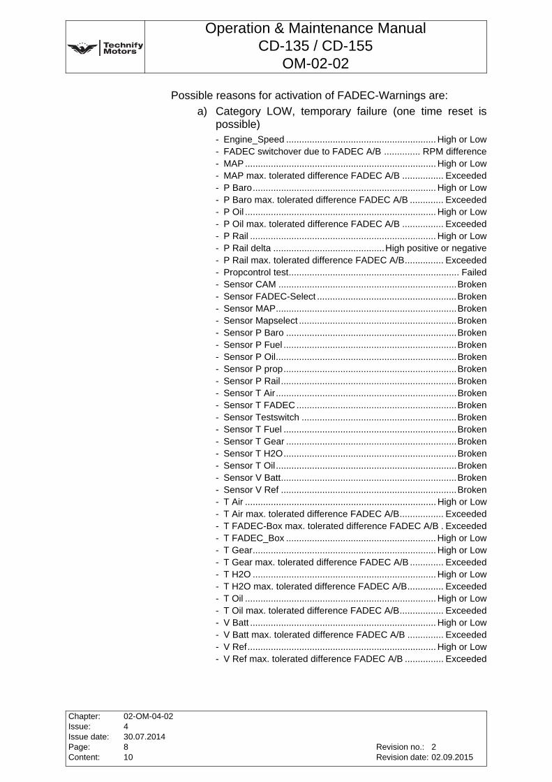
Possible reasons for activation of FADEC-Warnings are:
a) Category LOW, temporary failure (one time reset is possible)- Engine_Speed .......................................................... High or Low- FADEC switchover due to FADEC A/B .............. RPM difference- MAP .......................................................................... High or Low- MAP max. tolerated difference FADEC A/B ................ Exceeded- P Baro....................................................................... High or Low- P Baro max. tolerated difference FADEC A/B ............. Exceeded- P Oil .......................................................................... High or Low- P Oil max. tolerated difference FADEC A/B ................ Exceeded- P Rail ........................................................................ High or Low- P Rail delta ...........................................High positive or negative- P Rail max. tolerated difference FADEC A/B............... Exceeded- Propcontrol test.................................................................. Failed- Sensor CAM .....................................................................Broken- Sensor FADEC-Select ......................................................Broken- Sensor MAP......................................................................Broken- Sensor Mapselect .............................................................Broken- Sensor P Baro ..................................................................Broken- Sensor P Fuel ...................................................................Broken- Sensor P Oil......................................................................Broken- Sensor P prop...................................................................Broken- Sensor P Rail....................................................................Broken- Sensor T Air......................................................................Broken- Sensor T FADEC ..............................................................Broken- Sensor Testswitch ............................................................Broken- Sensor T Fuel ...................................................................Broken- Sensor T Gear ..................................................................Broken- Sensor T H2O...................................................................Broken- Sensor T Oil......................................................................Broken- Sensor V Batt....................................................................Broken- Sensor V Ref ....................................................................Broken- T Air .......................................................................... High or Low- T Air max. tolerated difference FADEC A/B................. Exceeded- T FADEC-Box max. tolerated difference FADEC A/B . Exceeded- T FADEC_Box .......................................................... High or Low- T Gear....................................................................... High or Low- T Gear max. tolerated difference FADEC A/B ............. Exceeded- T H2O ....................................................................... High or Low- T H2O max. tolerated difference FADEC A/B.............. Exceeded- T Oil .......................................................................... High or Low- T Oil max. tolerated difference FADEC A/B................. Exceeded- V Batt ........................................................................ High or Low- V Batt max. tolerated difference FADEC A/B .............. Exceeded- V Ref......................................................................... High or Low- V Ref max. tolerated difference FADEC A/B ............... Exceeded
Chapter:Issue:Issue date:Page:Content:
02-OM-04-02430.07.2014810
Revision no.:Revision date:
202.09.2015
Operation & Maintenance ManualCD-135 / CD-155
OM-02-02
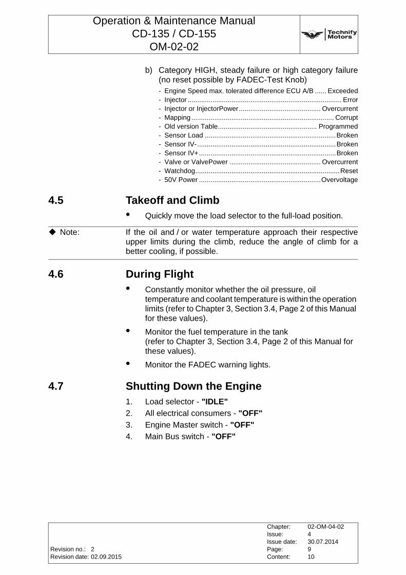
b) Category HIGH, steady failure or high category failure (no reset possible by FADEC-Test Knob)- Engine Speed max. tolerated difference ECU A/B ...... Exceeded- Injector ................................................................................. Error- Injector or InjectorPower........................................... Overcurrent- Mapping ........................................................................... Corrupt- Old version Table.................................................... Programmed- Sensor Load .....................................................................Broken- Sensor IV-.........................................................................Broken- Sensor IV+........................................................................Broken- Valve or ValvePower ................................................ Overcurrent- Watchdog............................................................................Reset- 50V Power ................................................................Overvoltage
4.5 Takeoff and Climb• Quickly move the load selector to the full-load position.
4.6 During Flight• Constantly monitor whether the oil pressure, oil
temperature and coolant temperature is within the operation limits (refer to Chapter 3, Section 3.4, Page 2 of this Manual for these values).
• Monitor the fuel temperature in the tank (refer to Chapter 3, Section 3.4, Page 2 of this Manual for these values).
• Monitor the FADEC warning lights.
4.7 Shutting Down the Engine1. Load selector - "IDLE"
2. All electrical consumers - "OFF"
3. Engine Master switch - "OFF"
4. Main Bus switch - "OFF"
Note: If the oil and / or water temperature approach their respective upper limits during the climb, reduce the angle of climb for a better cooling, if possible.
Revision no.:Revision date:
Chapter:Issue:Issue date:Page:Content:
02-OM-04-02430.07.2014910
202.09.2015
Operation & Maintenance ManualCD-135 / CD-155
OM-02-02
This page intentionally left blank
Chapter:Issue:Issue date:Page:Content:
02-OM-04-02430.07.20141010
Revision no.:Revision date:
202.09.2015
Operation & Maintenance ManualCD-135 / CD-155
OM-02-02
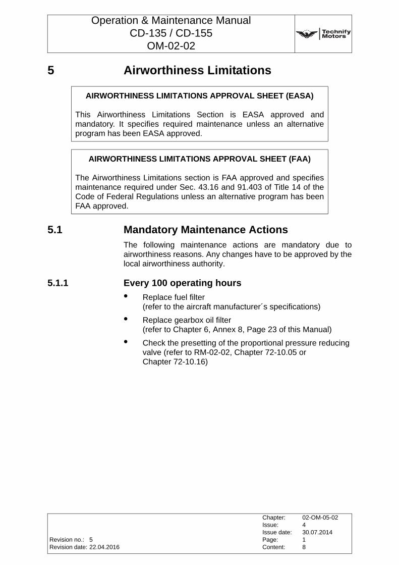
5 Airworthiness Limitations
5.1 Mandatory Maintenance ActionsThe following maintenance actions are mandatory due to airworthiness reasons. Any changes have to be approved by the local airworthiness authority.
5.1.1 Every 100 operating hours
• Replace fuel filter(refer to the aircraft manufacturer´s specifications)
• Replace gearbox oil filter(refer to Chapter 6, Annex 8, Page 23 of this Manual)
• Check the presetting of the proportional pressure reducing valve (refer to RM-02-02, Chapter 72-10.05 or Chapter 72-10.16)
AIRWORTHINESS LIMITATIONS APPROVAL SHEET (EASA)
This Airworthiness Limitations Section is EASA approved and mandatory. It specifies required maintenance unless an alternative program has been EASA approved.
AIRWORTHINESS LIMITATIONS APPROVAL SHEET (FAA)
The Airworthiness Limitations section is FAA approved and specifies maintenance required under Sec. 43.16 and 91.403 of Title 14 of the Code of Federal Regulations unless an alternative program has been FAA approved.
Revision no.:Revision date:
Chapter:Issue:Issue date:Page:Content:
02-OM-05-02430.07.201418
522.04.2016
Operation & Maintenance ManualCD-135 / CD-155
OM-02-02
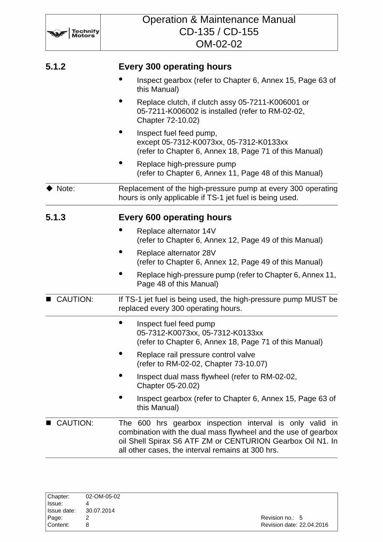
5.1.2 Every 300 operating hours
• Inspect gearbox (refer to Chapter 6, Annex 15, Page 63 of this Manual)
• Replace clutch, if clutch assy 05-7211-K006001 or 05-7211-K006002 is installed (refer to RM-02-02, Chapter 72-10.02)
• Inspect fuel feed pump, except 05-7312-K0073xx, 05-7312-K0133xx(refer to Chapter 6, Annex 18, Page 71 of this Manual)
• Replace high-pressure pump(refer to Chapter 6, Annex 11, Page 48 of this Manual)
5.1.3 Every 600 operating hours
• Replace alternator 14V(refer to Chapter 6, Annex 12, Page 49 of this Manual)
• Replace alternator 28V(refer to Chapter 6, Annex 12, Page 49 of this Manual)
• Replace high-pressure pump (refer to Chapter 6, Annex 11, Page 48 of this Manual)
• Inspect fuel feed pump 05-7312-K0073xx, 05-7312-K0133xx(refer to Chapter 6, Annex 18, Page 71 of this Manual)
• Replace rail pressure control valve (refer to RM-02-02, Chapter 73-10.07)
• Inspect dual mass flywheel (refer to RM-02-02, Chapter 05-20.02)
• Inspect gearbox (refer to Chapter 6, Annex 15, Page 63 of this Manual)
Note: Replacement of the high-pressure pump at every 300 operating hours is only applicable if TS-1 jet fuel is being used.
CAUTION: If TS-1 jet fuel is being used, the high-pressure pump MUST be replaced every 300 operating hours.
CAUTION: The 600 hrs gearbox inspection interval is only valid in combination with the dual mass flywheel and the use of gearbox oil Shell Spirax S6 ATF ZM or CENTURION Gearbox Oil N1. In all other cases, the interval remains at 300 hrs.
Chapter:Issue:Issue date:Page:Content:
02-OM-05-02430.07.201428
Revision no.:Revision date:
522.04.2016
Operation & Maintenance ManualCD-135 / CD-155
OM-02-02
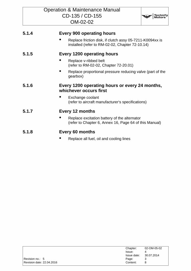
5.1.4 Every 900 operating hours
• Replace friction disk, if clutch assy 05-7211-K0094xx is installed (refer to RM-02-02, Chapter 72-10.14)
5.1.5 Every 1200 operating hours
• Replace v-ribbed belt(refer to RM-02-02, Chapter 72-20.01)
• Replace proportional pressure reducing valve (part of the gearbox)
5.1.6 Every 1200 operating hours or every 24 months, whichever occurs first
• Exchange coolant(refer to aircraft manufacturer‘s specifications)
5.1.7 Every 12 months
• Replace excitation battery of the alternator(refer to Chapter 6, Annex 16, Page 64 of this Manual)
5.1.8 Every 60 months
• Replace all fuel, oil and cooling lines
Revision no.:Revision date:
Chapter:Issue:Issue date:Page:Content:
02-OM-05-02430.07.201438
522.04.2016
Operation & Maintenance ManualCD-135 / CD-155
OM-02-02
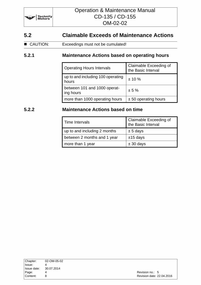
5.2 Claimable Exceeds of Maintenance Actions
5.2.1 Maintenance Actions based on operating hours
5.2.2 Maintenance Actions based on time
CAUTION: Exceedings must not be cumulated!
Operating Hours IntervalsClaimable Exceeding of the Basic Interval
up to and including 100 operating hours
± 10 %
between 101 and 1000 operat-ing hours
± 5 %
more than 1000 operating hours ± 50 operating hours
Time IntervalsClaimable Exceeding of the Basic Interval
up to and including 2 months ± 5 days
between 2 months and 1 year ±15 days
more than 1 year ± 30 days
Chapter:Issue:Issue date:Page:Content:
02-OM-05-02430.07.201448
Revision no.:Revision date:
522.04.2016
Operation & Maintenance ManualCD-135 / CD-155
OM-02-02
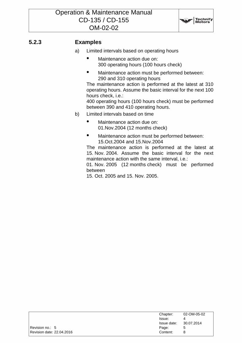
5.2.3 Examples
a) Limited intervals based on operating hours
• Maintenance action due on: 300 operating hours (100 hours check)
• Maintenance action must be performed between: 290 and 310 operating hours
The maintenance action is performed at the latest at 310 operating hours. Assume the basic interval for the next 100 hours check, i.e.:400 operating hours (100 hours check) must be performed between 390 and 410 operating hours.
b) Limited intervals based on time
• Maintenance action due on: 01.Nov.2004 (12 months check)
• Maintenance action must be performed between:15.Oct.2004 and 15.Nov.2004
The maintenance action is performed at the latest at 15. Nov. 2004. Assume the basic interval for the next maintenance action with the same interval, i.e.:01. Nov. 2005 (12 months check) must be performed between 15. Oct. 2005 and 15. Nov. 2005.
Revision no.:Revision date:
Chapter:Issue:Issue date:Page:Content:
02-OM-05-02430.07.201458
522.04.2016
Operation & Maintenance ManualCD-135 / CD-155
OM-02-02
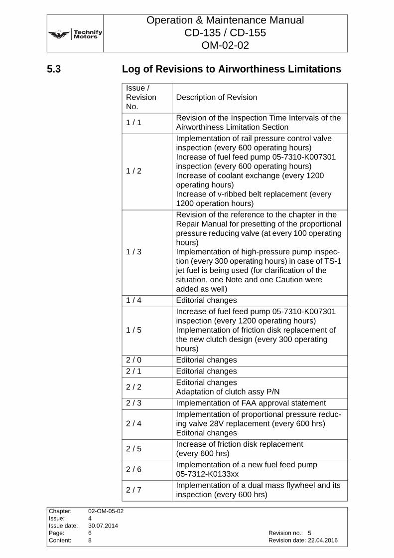
5.3 Log of Revisions to Airworthiness Limitations
Issue / Revision No.
Description of Revision
1 / 1Revision of the Inspection Time Intervals of the Airworthiness Limitation Section
1 / 2
Implementation of rail pressure control valve inspection (every 600 operating hours)Increase of fuel feed pump 05-7310-K007301 inspection (every 600 operating hours)Increase of coolant exchange (every 1200 operating hours)Increase of v-ribbed belt replacement (every 1200 operation hours)
1 / 3
Revision of the reference to the chapter in the Repair Manual for presetting of the proportional pressure reducing valve (at every 100 operating hours)Implementation of high-pressure pump inspec-tion (every 300 operating hours) in case of TS-1 jet fuel is being used (for clarification of the situation, one Note and one Caution were added as well)
1 / 4 Editorial changes
1 / 5
Increase of fuel feed pump 05-7310-K007301 inspection (every 1200 operating hours)Implementation of friction disk replacement of the new clutch design (every 300 operating hours)
2 / 0 Editorial changes
2 / 1 Editorial changes
2 / 2Editorial changesAdaptation of clutch assy P/N
2 / 3 Implementation of FAA approval statement
2 / 4 Implementation of proportional pressure reduc-ing valve 28V replacement (every 600 hrs)Editorial changes
2 / 5Increase of friction disk replacement (every 600 hrs)
2 / 6Implementation of a new fuel feed pump 05-7312-K0133xx
2 / 7Implementation of a dual mass flywheel and its inspection (every 600 hrs)
Chapter:Issue:Issue date:Page:Content:
02-OM-05-02430.07.201468
Revision no.:Revision date:
522.04.2016
Operation & Maintenance ManualCD-135 / CD-155
OM-02-02
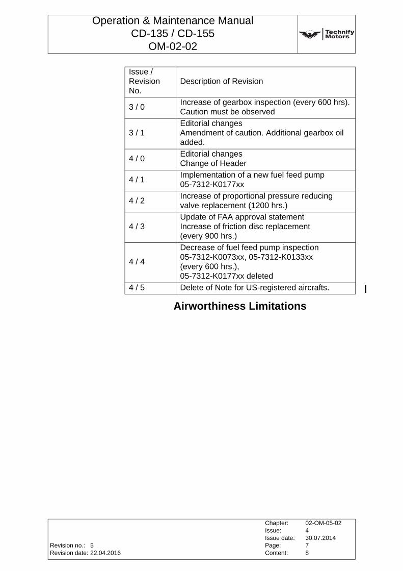
Airworthiness Limitations
3 / 0Increase of gearbox inspection (every 600 hrs).Caution must be observed
3 / 1 Editorial changesAmendment of caution. Additional gearbox oil added.
4 / 0 Editorial changesChange of Header
4 / 1 Implementation of a new fuel feed pump 05-7312-K0177xx
4 / 2 Increase of proportional pressure reducing valve replacement (1200 hrs.)
4 / 3 Update of FAA approval statementIncrease of friction disc replacement (every 900 hrs.)
4 / 4
Decrease of fuel feed pump inspection 05-7312-K0073xx, 05-7312-K0133xx (every 600 hrs.), 05-7312-K0177xx deleted
4 / 5 Delete of Note for US-registered aircrafts.
Issue / Revision No.
Description of Revision
Revision no.:Revision date:
Chapter:Issue:Issue date:Page:Content:
02-OM-05-02430.07.201478
522.04.2016

Operation & Maintenance ManualCD-135 / CD-155
OM-02-02
This page intentionally left blank
Chapter:Issue:Issue date:Page:Content:
02-OM-05-02430.07.201488
Revision no.:Revision date:
522.04.2016
Operation & Maintenance ManualCD-135 / CD-155
OM-02-02
6 Maintenance SchedulesThe specified maintenance schedule applies to all aircraft regardless of type and ensures the reliability of the engine. The maintenance work on Technify Motors GmbH engines must be carried out after specific time intervals or upon reaching a specific number of operating hours. It is recommended to perform a "Pre-flight inspection" before each flight. Components that are not part of the scope of supply of the engine must be maintained and checked in accordance with the aircraft manufacturer's specifications (refer also to the aircraft manual).
WARNING: The entire engine has a service life ("time between replacement") recommended by the manufacturer; refer to Service Bulletin TM TAE 125-0001.
WARNING: It is strongly recommended that the maintenance intervals specified by the manufacturer will be observed. Non-compliance with the maintenance schedule can lead, among other things, to a forfeiture of any claims of warranty.
Note: For this engine there is a lifetime extension program for service life (time between replacement). Up-to-date information about the recommended service life is published in Service BulletinTM TAE 125-0001.
Note: Further information concerning service partners and servicing or parts to be replaced is published in Service BulletinTM TAE 000-0003.
Note: Technify Motors GmbH should be informed immediately in the event of any engine malfunction and diagnosis.
Revision no.:Revision date:
Chapter:Issue:Issue date:Page:Content:
02-OM-06-02430.07.2014174
518.09.2015
Operation & Maintenance ManualCD-135 / CD-155
OM-02-02
6.1 "Pre-flight Check"• All switches - "OFF"
• Check the engine oil level (refer to IM-02-02, Chapter 4 for filling quantities)
• Check gearbox oil level (refer to Annex 9, Page 31 of this Chapter)
• Check each of the fuel tanks for water and debris
• Electrical Master switch - "ON"
• Engine Master switch - "ON"
• Check coolant level by observing control lamp
• Start the engine according to Chapter 4, Section 4.2, Page 2 of this Manual and conduct a FADEC test run
6.2 Maintenance Actions based on Operating Hours
CAUTION: When checking the engine oil level screw in the dipstick completely!
CAUTION: Checking the oil level at operating start temperature but not until 5 minutes after shut down the engine.
Note: The engine oil level can vary, because of the back flow of engine oil. After 5 minutes 80% of the engine oil returned into the oil pan, after 15 minutes 90% and after 30 minutes 100%.
CAUTION: The lamp “Water level“ must be OFF.
WARNING: Under extreme conditions such as low usage combined with operation in a salt-water environment, or in a a very dusty or sandy environment shorter maintenance and inspection intervals are recommended for your own safety.
Note: Chapter 1, Section 1.10, Page 5 of this Manual must be observed.
Chapter:Issue:Issue date:Page:Content:
02-OM-06-02430.07.2014274
Revision no.:Revision date:
518.09.2015
Operation & Maintenance ManualCD-135 / CD-155
OM-02-02
6.2.1 After the 3rd - 6th operating hour
• Check the oil system for leakage (refer to Annex 2, Page 12 of this Chapter)
• Check the fuel system for leakage(refer to Annex 2, Page 12 of this Chapter)
• Check the cooling system for leakage (refer to Annex 3, Page 13 of this Chapter)
• Visual inspection of the air filter
• Visual inspection of hoses and fuel pipes
(refer to RM-02-02, Chapter 05-20.03)
• Visual inspection of the FADEC sensors (refer to Annex 7, Page 19 of this Chapter)
• Visual inspection of the exhaust system
• Visual inspection of the v-ribbed belt(refer to Annex 1, Page 11 of this Chapter)
• Perform an engine test run according to Chapter 4, Section 4.4.2, Page 5 of this Manual, read out the FADEC. E-mail both the Real Time Log Files and Event Log Files to Technify Motors GmbH (refer to Annex 10, Page 37 of this Chapter)
• Exchange the gearbox oil filter (refer to Annex 8, Page 24 of this Chapter); The used gearbox oil filter should be labeled, stored in a clean container and made available to Technify Motors GmbH on request for the complete engine life time. The sample will be required for a later long-run analysis. The label must show the aircraft serial number, registration number, engine serial number, operation time and date.
• Check the presetting of the proportional pressure reducing valve (refer to RM-02-02, Chapter 72-10.05 or Chapter 72-10.16)
Revision no.:Revision date:
Chapter:Issue:Issue date:Page:Content:
02-OM-06-02430.07.2014374
518.09.2015
Operation & Maintenance ManualCD-135 / CD-155
OM-02-02
6.2.2 Every 100 operating hours
• Visual inspection of the air filter
• Visual inspection of the cooling system
• Visual inspection of the oil system(refer to Annex 2, Page 12 of this Chapter)
• Visual inspection of the fuel system(refer to Annex 2, Page 12 of this Chapter)
• Visual inspection of the FADEC sensors (refer to Annex 7, Page 19 of this Chapter)
• Visual inspection of the exhaust system
• Visual inspection of the v-ribbed belt (refer to Annex 1, Page 11 of this Chapter)
• Visual inspection of the clamp on the turbocharger
• Visual inspection of all fuel, oil, cooling system lines and hoses for chafe marks (refer to RM-02-02 Chapter 05-20.03)
• Visual inspection of the engine mount for chafe marks
• Check the airframe fuel pump (refer to the aircraft manufacturer's specifications)
• Test the cooling system under pressure at 2.0 bar Duration: 2 minutes. Max. 2.0 bar must not be exceeded! Afterwards check for leakage (refer to the aircraft manufacturer's specifications).
• Perform an engine test run according to Chapter 4, Section 4.4.2, Page 5 of this Manual and read out the FADEC.E-mail both the Real Time Log Files and Event Log Files to Technify Motors GmbH (refer to Annex 10, Page 37 of this Chapter).
• Exchange the engine oil and the oil filter (refer to Annex 5, Page 15 of this Chapter); A sample of the oil and the used oil filter should be labeled, stored in a clean container and made available to Technify Motors GmbH on request for the complete engine life time. The sample will be required for a later long-run analysis. The label must show the aircraft serial number, registration number, engine serial number, operation time and date.Quantity of oil to be taken for sample: 100ml
• Check the mixture ratio of the coolant
• Replace the fuel filter (refer to the aircraft manufacturer's specifications)
Chapter:Issue:Issue date:Page:Content:
02-OM-06-02430.07.2014474
Revision no.:Revision date:
518.09.2015
Operation & Maintenance ManualCD-135 / CD-155
OM-02-02
• Exchange gearbox oil and the gearbox oil filter (refer to Annex 13, Page 51 of this Chapter); A sample of the oil and the used gearbox oil filter should be labeled, stored in a clean container and made available to Technify Motors GmbH on request for the complete engine life time. The sample will be required for later long-run analysis. The label must show the aircraft serial number, registration number, engine serial number, operation time and date.Quantity of oil to be taken for sample: 100ml
• Check the presetting of the proportional pressure reducing valve (refer to RM-02-02, Chapter 72-10.05 or Chapter 72-10.16)
6.2.3 Every 200 operating hours
• Carry out all steps described in Section 6.2.2, Page 4 of this Chapter
• Replace air filter
6.2.4 Every 300 operating hours
• Carry out all steps described in Section 6.2.2, Page 4 of this Chapter
• Replace clutch, if clutch assy 05-7211-K006001 or 05-7211-K006002 is installed (refer to RM-02-02, Chapter 72-10.02)
• Inspect gearbox (refer to Annex 15, Page 65 of this Chapter)
• Inspect fuel feed pump, except 05-7312-K0073xx, 05-7312-K0133xx(refer to Chapter 6, Annex 18, Page 73 of this Manual)
• Replace high-pressure pump (refer to Annex 11, Page 49 of this Chapter)
Note: When replacing the air filter check carefully that no foreign objects are in it.
Note: Replacement of the high-pressure pump at every 300 operating hours is only applicable if TS-1 jet fuel is being used.
Revision no.:Revision date:
Chapter:Issue:Issue date:Page:Content:
02-OM-06-02430.07.2014574
518.09.2015
Operation & Maintenance ManualCD-135 / CD-155
OM-02-02
6.2.5 Every 600 operating hours
• Carry out all steps described in Section 6.2.3, Page 5 of this Chapter
• Carry out all steps described in Section 6.2.4, Page 5 of this Chapter
• Replace alternator 14V (refer to Annex 12, Page 50 of this Chapter)
• Replace alternator 28V (refer to Annex 12, Page 50 of this Chapter)
• Replace high-pressure pump (refer to Annex 11, Page 49 of this Chapter)
• Inspect fuel feed pump, 05-7312-K0073xx, 05-7312-K0133xx(refer to Annex 18, Page 73 of this Chapter)
• Replace rail pressure control valve(refer to RM-02-02, Chapter 73-10.07)
• Inspect dual mass flywheel (refer to RM-02-02, Chapter 05-20.02)
• Inspect AltReg loom (refer to RM-02-02, Chapter 05-20.01)
• Inspect gearbox (refer to Annex 15, Page 65 of this Chapter)
6.2.6 Every 900 operating hours
• Carry out all steps described in Section 6.2.4, Page 5 of this Chapter
• Replace timing chain (refer to RM-02-02, Chapter 72-30.02)
• Replace friction disk, if clutch assy 05-7211-K0094xx is installed (refer to RM-02-02, Chapter 72-10.14)
CAUTION: If TS-1 jet fuel is being used, the high-pressure pump MUST be replaced every 300 operating hours.
CAUTION: The 600 hrs gearbox inspection interval is only valid incombination with the dual mass flywheel and with the use of gearbox oil Shell Spirax S6 ATF ZM or CENTURION Gearbox Oil N1. In all other cases, the interval remains at 300 hrs.
Chapter:Issue:Issue date:Page:Content:
02-OM-06-02430.07.2014674
Revision no.:Revision date:
518.09.2015
Operation & Maintenance ManualCD-135 / CD-155
OM-02-02
6.2.7 Every 1200 operating hours (only applicable for CD-135)
• Carry out all steps described in Section 6.2.5, Page 6 of this Chapter
• Replace v-ribbed belt (refer to RM-02-02, Chapter 72-20.01)
• Exchange coolant (refer to the aircraft manufacturer's specifications)
• Replace coolant hose 05-7523-K0048xx (only DA42 installations)
• Visual inspection of the gasket of the turbocharger oil return line, replace if necessary.
• Replace proportional pressure reducing valve (part of the gearbox)
6.2.8 Every 1200 operating hours (only applicable for CD-155)
• Carry out all steps described in Section Section 6.2.5, Page 6 of this Chapter
• Replace engine shock mounts (refer to RM-02-02, Chapter 71-20.01; 71-20.02; 71-20.03)
• Replace v-ribbed belt (refer to RM-02-02, Chapter 72-20.01)
• Exchange coolant(refer to the aircraft manufacturer's specifications)
• Replace proportional pressure reducing valve (part of the gearbox)
Revision no.:Revision date:
Chapter:Issue:Issue date:Page:Content:
02-OM-06-02430.07.2014774
518.09.2015
Operation & Maintenance ManualCD-135 / CD-155
OM-02-02
6.2.9 Every 1200 operating hours or every 24 months, whichever occurs first
• Exchange coolant(refer to aircraft manufacturer’s specifications)
6.2.10 Every 1500 operating hours (only applicable for CD-135)
• Carry out all steps described in Section 6.2.4, Page 5 of this Chapter
• Replace engine shock mounts (refer to RM-02-02, Chapter 71-20.01; 71-20.02; 71-20.03)
Chapter:Issue:Issue date:Page:Content:
02-OM-06-02430.07.2014874
Revision no.:Revision date:
518.09.2015
Operation & Maintenance ManualCD-135 / CD-155
OM-02-02
6.3 Maintenance Actions based on Time
6.3.1 Every month
• Protect engine against corrosion. Start-up the engine for at least 20 minutes (refer to Chapter 4, Section 4.2, Page 2 of this Manual)
6.3.2 Every 12 months
• Replace excitation battery of the alternator (refer to Annex 16, Page 66 of this Chapter)
• Exchange engine oil and oil filter (refer to Annex 5, Page 15 of this Chapter); A sample of the oil and the used oil filter should be labeled, stored in a clean container and made available to Technify Motors GmbH on request for the complete engine life time. The sample will be required for a later long-run analysis. The label must show the aircraft serial number, registration number, engine serial number, operation time and date. Quantity of oil to be taken for sample: 100ml
• Exchange gearbox oil and gearbox oil filter (refer to Annex 13, Page 51 of this Chapter); A sample of the oil and the used gearbox oil filter should be labeled, stored in a clean container and made available to Technify Motors GmbH on request for the complete engine life time. The sample will be required for a later long-run analysis. The label must show the aircraft serial number, registration number, engine serial number, operation time and date. Quantity of oil to be taken for sample: 100ml
WARNING: Under extreme conditions such as low usage combined with operation in a salt-water environment, or in a very dusty and sandy environment, shorter maintenance and inspection intervals are recommended for your own safety.
Note: Chapter 1, Section 1.10, Page 5 of this Manual must be observed.
Revision no.:Revision date:
Chapter:Issue:Issue date:Page:Content:
02-OM-06-02430.07.2014974
518.09.2015
Operation & Maintenance ManualCD-135 / CD-155
OM-02-02
6.3.3 Every 24 months
• Exchange coolant (refer to the aircraft manufacturer's specifications)
6.3.4 Every 60 months
• Replace all fuel, oil and cooling system lines(refer to RM-02-02, Chapter 05-20.03.)
• FADEC maintenance (to be carried out by the engine manufacturer)
Note: Flexible hose / hose assemblies replacement times are in-service times. In-service times must be determined by
1. the date the aircraft was licensed, if new or
2. the date entered in the logbook for the replacement hose placed in service.
Do not use the date stamped on the hose / hose assembly, as time may be included for shelf life, and not in-service use.
Chapter:Issue:Issue date:Page:Content:
02-OM-06-02430.07.20141074
Revision no.:Revision date:
518.09.2015
Operation & Maintenance ManualCD-135 / CD-155
OM-02-02
Annex 1 Inspecting the V-Ribbed BeltThis is a general visual inspection. The v-ribbed belt is to be checked for indications of wear such as abrasion and cracks. The v-ribbed belt tension is determined by spring pressure automatically.
Revision no.:Revision date:
Chapter:Issue:Issue date:Page:Content:
02-OM-06-02430.07.20141174
518.09.2015
Operation & Maintenance ManualCD-135 / CD-155
OM-02-02
Annex 2 Inspecting the Oil and Fuel System for LeakageThis is a visual inspection. Check all pipes, pipe joints, supply connections and engine housing separation points (e.g. cylinder head gasket, cylinder head cover gasket) for leakage, seepage points and correct routing. Visual inspection of oil for water contamination and water for oil contamination. For more details see RM-02-02 Chapter 05-20.03.
WARNING: No leaks or seepage points are permitted!
Chapter:Issue:Issue date:Page:Content:
02-OM-06-02430.07.20141274
Revision no.:Revision date:
518.09.2015
Operation & Maintenance ManualCD-135 / CD-155
OM-02-02
Annex 3 Inspecting the Cooling System for LeakageThis is a visual inspection. The pipes, pipe joints and supply connections are inspected for leakage and seepage points.
WARNING: No leakage and seepage points are permitted! No coolant loss during operation is permitted! Any coolant loss must be followed immediately by a technical inspection, as this can lead to engine damage and failure!
Revision no.:Revision date:
Chapter:Issue:Issue date:Page:Content:
02-OM-06-02430.07.20141374
518.09.2015
Operation & Maintenance ManualCD-135 / CD-155
OM-02-02
Annex 4 Engine Test RunCheck the starting behavior:
1. Start the engine according toChapter 4, Section 4.2, Page 2 of this Manual.
2. Warm up the engine according toChapter 4, Section 4.3, Page 3 of this Manual.
3. Perform the engine test run according toChapter 4, Section 4.4.2, Page 5 of this Manual.
4. Shut down the engine according toChapter 4, Section 4.7, Page 9 of this Manual.
CAUTION: Do not overheat the starter. Do not operate the starter for more than 10 seconds. After operating the starter, let it cool down for 20 seconds. After six attempts to start the engine, let the starter cool down for half an hour.
Chapter:Issue:Issue date:Page:Content:
02-OM-06-02430.07.20141474
Revision no.:Revision date:
518.09.2015
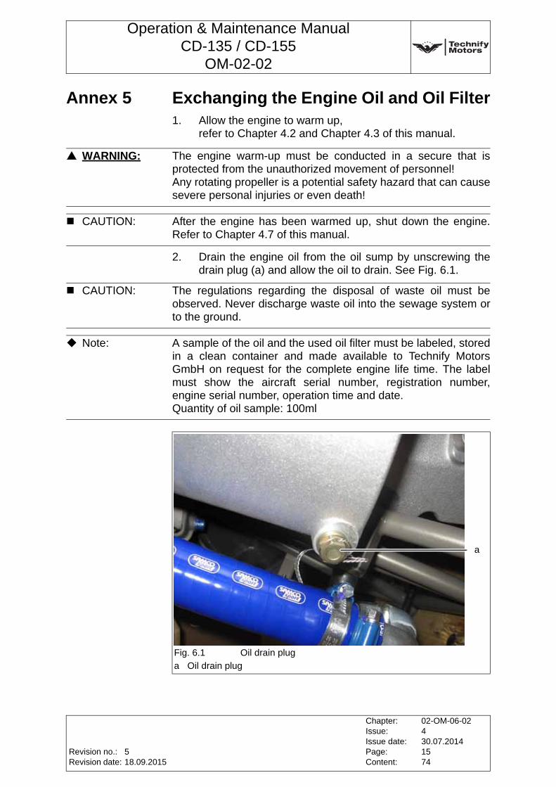
Operation & Maintenance ManualCD-135 / CD-155
OM-02-02
Annex 5 Exchanging the Engine Oil and Oil Filter1. Allow the engine to warm up,
refer to Chapter 4.2 and Chapter 4.3 of this manual.
2. Drain the engine oil from the oil sump by unscrewing the drain plug (a) and allow the oil to drain. See Fig. 6.1.
WARNING: The engine warm-up must be conducted in a secure that is protected from the unauthorized movement of personnel!Any rotating propeller is a potential safety hazard that can cause severe personal injuries or even death!
CAUTION: After the engine has been warmed up, shut down the engine. Refer to Chapter 4.7 of this manual.
CAUTION: The regulations regarding the disposal of waste oil must be observed. Never discharge waste oil into the sewage system or to the ground.
Note: A sample of the oil and the used oil filter must be labeled, stored in a clean container and made available to Technify Motors GmbH on request for the complete engine life time. The label must show the aircraft serial number, registration number, engine serial number, operation time and date. Quantity of oil sample: 100ml
Fig. 6.1 Oil drain plug
a Oil drain plug
a
Revision no.:Revision date:
Chapter:Issue:Issue date:Page:Content:
02-OM-06-02430.07.20141574
518.09.2015
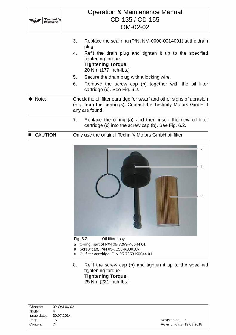
Operation & Maintenance ManualCD-135 / CD-155
OM-02-02
3. Replace the seal ring (P/N: NM-0000-0014001) at the drain plug.
4. Refit the drain plug and tighten it up to the specified tightening torque.Tightening Torque:20 Nm (177 inch-lbs.)
5. Secure the drain plug with a locking wire.
6. Remove the screw cap (b) together with the oil filter cartridge (c). See Fig. 6.2.
7. Replace the o-ring (a) and then insert the new oil filter cartridge (c) into the screw cap (b). See Fig. 6.2.
8. Refit the screw cap (b) and tighten it up to the specified tightening torque.Tightening Torque:25 Nm (221 inch-lbs.)
Note: Check the oil filter cartridge for swarf and other signs of abrasion (e.g. from the bearings). Contact the Technify Motors GmbH if any are found.
CAUTION: Only use the original Technify Motors GmbH oil filter.
Fig. 6.2 Oil filter assy
a O-ring, part of P/N 05-7253-K0044 01b Screw cap, P/N 05-7253-K00030xc Oil filter cartridge, P/N 05-7253-K0044 01
a
b
c
Chapter:Issue:Issue date:Page:Content:
02-OM-06-02430.07.20141674
Revision no.:Revision date:
518.09.2015
Operation & Maintenance ManualCD-135 / CD-155
OM-02-02
9. Refill the engine oil.
10. Check engine oil level.
11. Perform an Engine Test Run, refer to Annex 4 of this Chapter.
12. Check engine oil level. Refill, if necessary.
CAUTION: Only engine oil according to Chapter 3, Section 3.5, Page 4 of this Manual may be used.
Note: Due to differences in the oil cooler installation the oil quantity depends upon the aircraft manufacturer. A min. and max. oil quantity is specified by the engine manufacturer for installations.min.: 4.5 liters (1.2 gal)max.: 6.0 liters (1.6 gal)
Note: Before refilling, in order to mix the oil and the additives, either shake the engine oil bottle, or stir the oil barrel.
Note: After checking the engine oil level, screw in the dipstick completely.
Revision no.:Revision date:
Chapter:Issue:Issue date:Page:Content:
02-OM-06-02430.07.20141774
518.09.2015
Operation & Maintenance ManualCD-135 / CD-155
OM-02-02
Annex 6 Cleaning the EngineThe engine must be cleaned with care. If leakage points are found, their positions must be clearly identified before they are cleaned. The engine must be cleaned only when it is cooled down. Generally, the use of cold cleaners is recommended (e.g. Eylert cleaner, Eylert P/N 89226)
The engine must be dried after cleaning, ideally with compressed air (8 bar).
CAUTION: Do not use any cleaners in the area of the clutch. Cleaners can damage the clutch!
CAUTION: The use of easily flammable and caustic cleaning agents is not allowed. Also, avoid cleaning the engine's electrical system, as this may be damaged. The use of high-pressure cleaning equipment is not allowed.
Chapter:Issue:Issue date:Page:Content:
02-OM-06-02430.07.20141874
Revision no.:Revision date:
518.09.2015
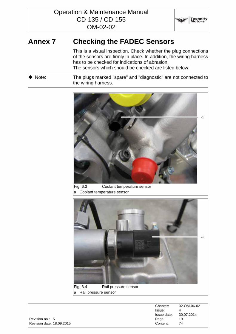
Operation & Maintenance ManualCD-135 / CD-155
OM-02-02
Annex 7 Checking the FADEC SensorsThis is a visual inspection. Check whether the plug connections of the sensors are firmly in place. In addition, the wiring harness has to be checked for indications of abrasion. The sensors which should be checked are listed below:
Note: The plugs marked "spare" and "diagnostic" are not connected to the wiring harness.
Fig. 6.3 Coolant temperature sensor
a Coolant temperature sensor
Fig. 6.4 Rail pressure sensor
a Rail pressure sensor
a
a
Revision no.:Revision date:
Chapter:Issue:Issue date:Page:Content:
02-OM-06-02430.07.20141974
518.09.2015
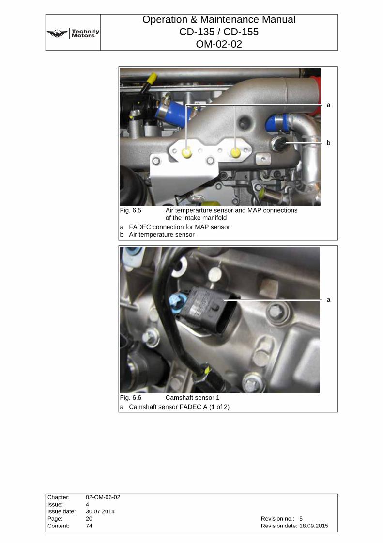
Operation & Maintenance ManualCD-135 / CD-155
OM-02-02
Fig. 6.5 Air temperarture sensor and MAP connectionsof the intake manifold
a FADEC connection for MAP sensorb Air temperature sensor
Fig. 6.6 Camshaft sensor 1
a Camshaft sensor FADEC A (1 of 2)
b
a
a
Chapter:Issue:Issue date:Page:Content:
02-OM-06-02430.07.20142074
Revision no.:Revision date:
518.09.2015
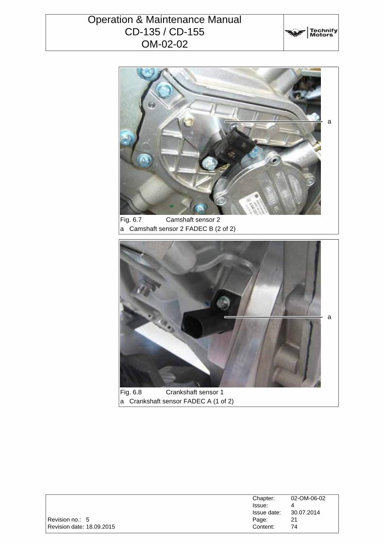
Operation & Maintenance ManualCD-135 / CD-155
OM-02-02
Fig. 6.7 Camshaft sensor 2
a Camshaft sensor 2 FADEC B (2 of 2)
Fig. 6.8 Crankshaft sensor 1
a Crankshaft sensor FADEC A (1 of 2)
a
a
Revision no.:Revision date:
Chapter:Issue:Issue date:Page:Content:
02-OM-06-02430.07.20142174
518.09.2015
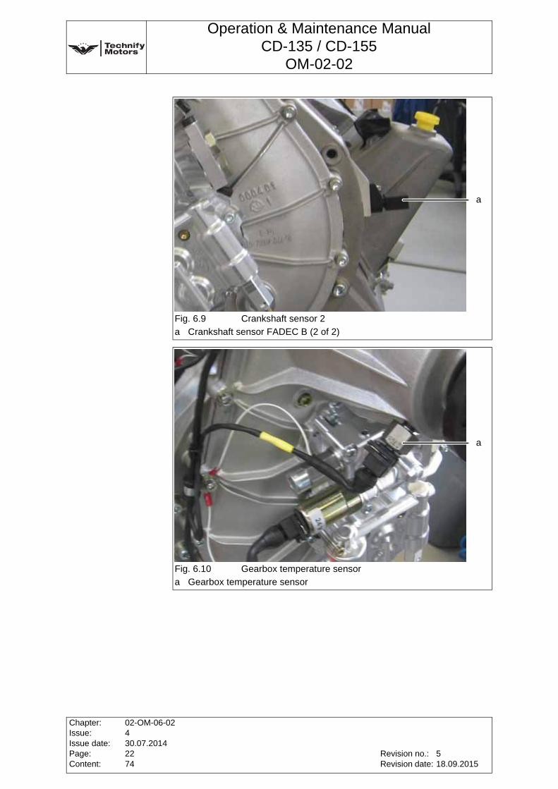
Operation & Maintenance ManualCD-135 / CD-155
OM-02-02
Fig. 6.9 Crankshaft sensor 2
a Crankshaft sensor FADEC B (2 of 2)
Fig. 6.10 Gearbox temperature sensor
a Gearbox temperature sensor
a
a
Chapter:Issue:Issue date:Page:Content:
02-OM-06-02430.07.20142274
Revision no.:Revision date:
518.09.2015
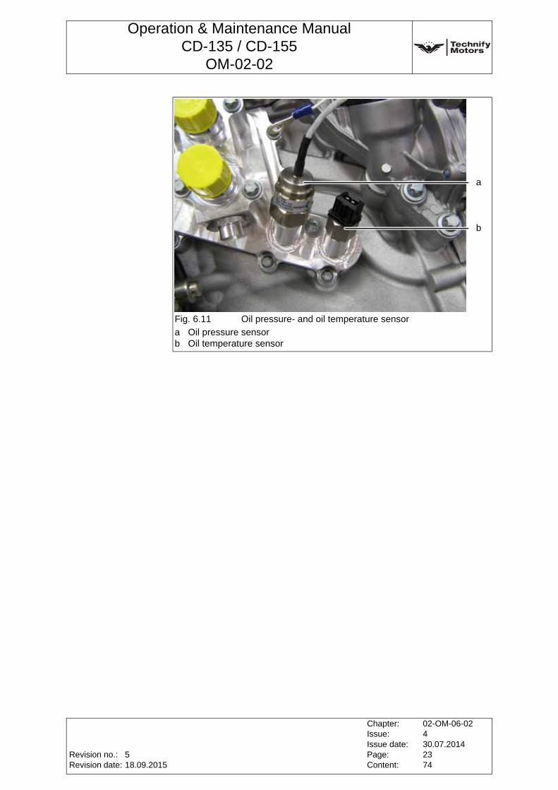
Operation & Maintenance ManualCD-135 / CD-155
OM-02-02
Fig. 6.11 Oil pressure- and oil temperature sensor
a Oil pressure sensorb Oil temperature sensor
a
b
Revision no.:Revision date:
Chapter:Issue:Issue date:Page:Content:
02-OM-06-02430.07.20142374
518.09.2015
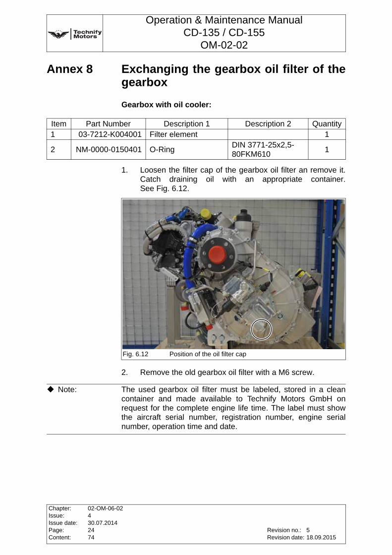
Operation & Maintenance ManualCD-135 / CD-155
OM-02-02
Annex 8 Exchanging the gearbox oil filter of the gearbox
Gearbox with oil cooler:
1. Loosen the filter cap of the gearbox oil filter an remove it. Catch draining oil with an appropriate container. See Fig. 6.12.
2. Remove the old gearbox oil filter with a M6 screw.
Item Part Number Description 1 Description 2 Quantity1 03-7212-K004001 Filter element 1
2 NM-0000-0150401 O-RingDIN 3771-25x2,5-80FKM610
1
Fig. 6.12 Position of the oil filter cap
Note: The used gearbox oil filter must be labeled, stored in a clean container and made available to Technify Motors GmbH on request for the complete engine life time. The label must show the aircraft serial number, registration number, engine serial number, operation time and date.
Chapter:Issue:Issue date:Page:Content:
02-OM-06-02430.07.20142474
Revision no.:Revision date:
518.09.2015
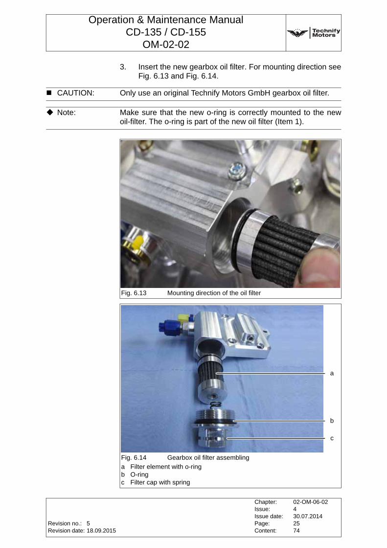
Operation & Maintenance ManualCD-135 / CD-155
OM-02-02
3. Insert the new gearbox oil filter. For mounting direction see Fig. 6.13 and Fig. 6.14.
CAUTION: Only use an original Technify Motors GmbH gearbox oil filter.
Note: Make sure that the new o-ring is correctly mounted to the new oil-filter. The o-ring is part of the new oil filter (Item 1).
Fig. 6.13 Mounting direction of the oil filter
Fig. 6.14 Gearbox oil filter assembling
a Filter element with o-ringb O-ringc Filter cap with spring
a
b
c
Revision no.:Revision date:
Chapter:Issue:Issue date:Page:Content:
02-OM-06-02430.07.20142574
518.09.2015
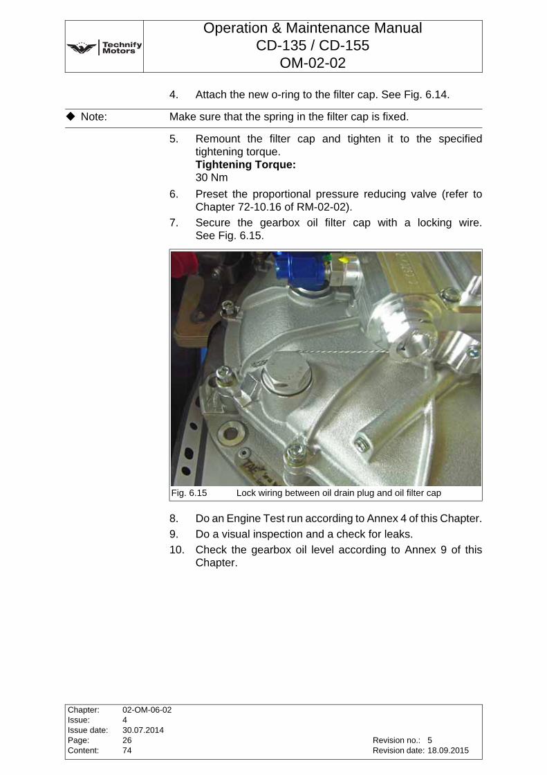
Operation & Maintenance ManualCD-135 / CD-155
OM-02-02
4. Attach the new o-ring to the filter cap. See Fig. 6.14.
5. Remount the filter cap and tighten it to the specified tightening torque.Tightening Torque:30 Nm
6. Preset the proportional pressure reducing valve (refer to Chapter 72-10.16 of RM-02-02).
7. Secure the gearbox oil filter cap with a locking wire. See Fig. 6.15.
8. Do an Engine Test run according to Annex 4 of this Chapter.
9. Do a visual inspection and a check for leaks.
10. Check the gearbox oil level according to Annex 9 of this Chapter.
Note: Make sure that the spring in the filter cap is fixed.
Fig. 6.15 Lock wiring between oil drain plug and oil filter cap
Chapter:Issue:Issue date:Page:Content:
02-OM-06-02430.07.20142674
Revision no.:Revision date:
518.09.2015
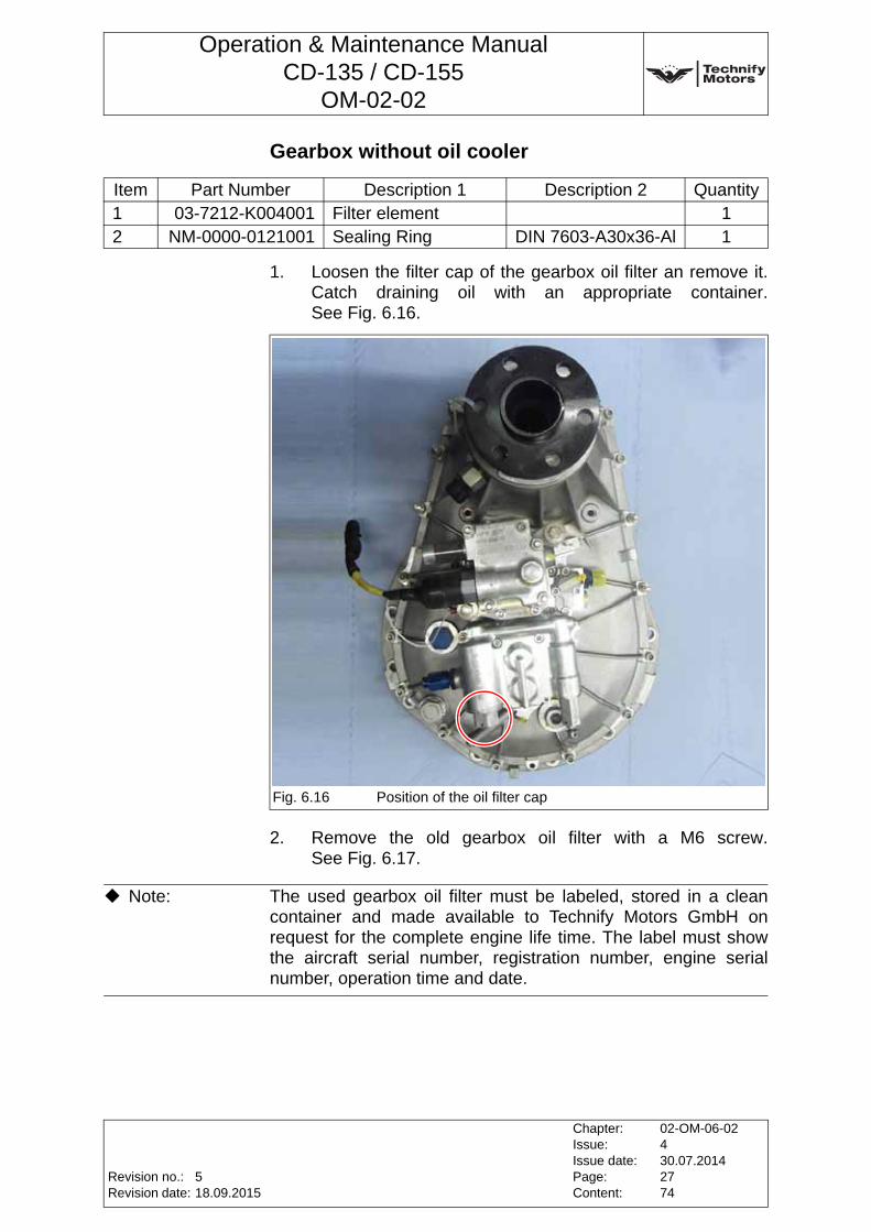
Operation & Maintenance ManualCD-135 / CD-155
OM-02-02
Gearbox without oil cooler
1. Loosen the filter cap of the gearbox oil filter an remove it. Catch draining oil with an appropriate container. See Fig. 6.16.
2. Remove the old gearbox oil filter with a M6 screw. See Fig. 6.17.
Item Part Number Description 1 Description 2 Quantity1 03-7212-K004001 Filter element 12 NM-0000-0121001 Sealing Ring DIN 7603-A30x36-Al 1
Fig. 6.16 Position of the oil filter cap
Note: The used gearbox oil filter must be labeled, stored in a clean container and made available to Technify Motors GmbH on request for the complete engine life time. The label must show the aircraft serial number, registration number, engine serial number, operation time and date.
Revision no.:Revision date:
Chapter:Issue:Issue date:Page:Content:
02-OM-06-02430.07.20142774
518.09.2015
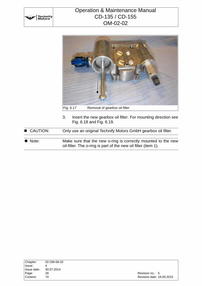
Operation & Maintenance ManualCD-135 / CD-155
OM-02-02
3. Insert the new gearbox oil filter. For mounting direction see Fig. 6.18 and Fig. 6.19.
Fig. 6.17 Removal of gearbox oil filter
CAUTION: Only use an original Technify Motors GmbH gearbox oil filter.
Note: Make sure that the new o-ring is correctly mounted to the new oil-filter. The o-ring is part of the new oil filter (item 1).
Chapter:Issue:Issue date:Page:Content:
02-OM-06-02430.07.20142874
Revision no.:Revision date:
518.09.2015
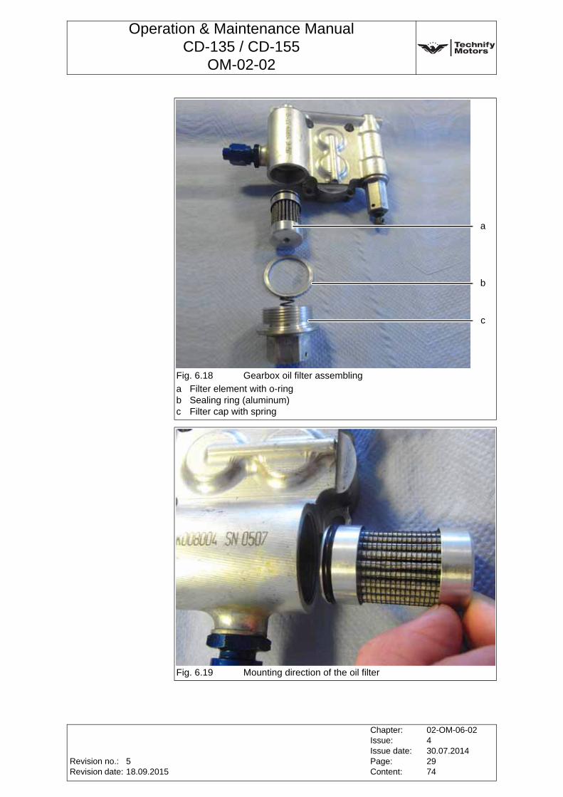
Operation & Maintenance ManualCD-135 / CD-155
OM-02-02
Fig. 6.18 Gearbox oil filter assembling
a Filter element with o-ringb Sealing ring (aluminum)c Filter cap with spring
Fig. 6.19 Mounting direction of the oil filter
a
b
c
Revision no.:Revision date:
Chapter:Issue:Issue date:Page:Content:
02-OM-06-02430.07.20142974
518.09.2015

Operation & Maintenance ManualCD-135 / CD-155
OM-02-02
4. Attach the new aluminum sealing ring to the filter cap. See Fig. 6.19.
5. Remount the filter cap and tighten it to the specified tightening torque.Tightening Torque:55 Nm
6. Preset the proportional pressure reducing valve. Refer to Chapter 72-10.05 of RM-02-02.
7. Secure the gearbox oil filter cap with a locking wire. See Fig. 6.20.
8. Do an Engine Test run according to Annex 4 of this Chapter.
9. Do a visual inspection and a check for leaks.
10. Check the gearbox oil level according to Annex 9 of this Chapter.
Note: Make sure that the spring in the filter cap is fixed.
Fig. 6.20 Lock wiring the oil filter cap, the proportional pressure reducingvalve and the gearbox housing
Chapter:Issue:Issue date:Page:Content:
02-OM-06-02430.07.20143074
Revision no.:Revision date:
518.09.2015
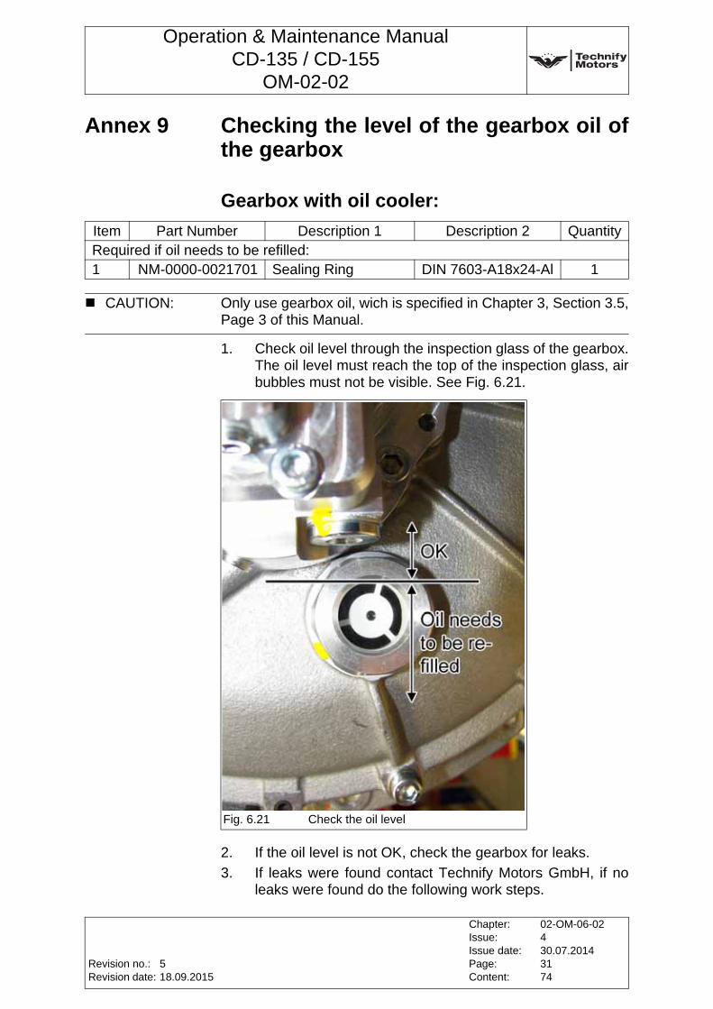
Operation & Maintenance ManualCD-135 / CD-155
OM-02-02
Annex 9 Checking the level of the gearbox oil of the gearbox
Gearbox with oil cooler:
1. Check oil level through the inspection glass of the gearbox. The oil level must reach the top of the inspection glass, air bubbles must not be visible. See Fig. 6.21.
2. If the oil level is not OK, check the gearbox for leaks.
3. If leaks were found contact Technify Motors GmbH, if no leaks were found do the following work steps.
Item Part Number Description 1 Description 2 QuantityRequired if oil needs to be refilled:1 NM-0000-0021701 Sealing Ring DIN 7603-A18x24-Al 1
CAUTION: Only use gearbox oil, wich is specified in Chapter 3, Section 3.5, Page 3 of this Manual.
Fig. 6.21 Check the oil level
Revision no.:Revision date:
Chapter:Issue:Issue date:Page:Content:
02-OM-06-02430.07.20143174
518.09.2015
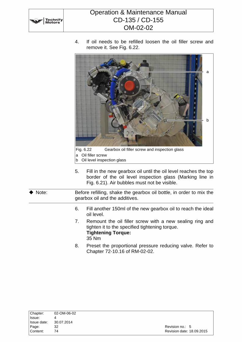
Operation & Maintenance ManualCD-135 / CD-155
OM-02-02
4. If oil needs to be refilled loosen the oil filler screw and remove it. See Fig. 6.22.
5. Fill in the new gearbox oil until the oil level reaches the top border of the oil level inspection glass (Marking line in Fig. 6.21). Air bubbles must not be visible.
6. Fill another 150ml of the new gearbox oil to reach the ideal oil level.
7. Remount the oil filler screw with a new sealing ring and tighten it to the specified tightening torque.Tightening Torque:35 Nm
8. Preset the proportional pressure reducing valve. Refer to Chapter 72-10.16 of RM-02-02.
Fig. 6.22 Gearbox oil filler screw and inspection glass
a Oil filler screwb Oil level inspection glass
a
b
Note: Before refilling, shake the gearbox oil bottle, in order to mix the gearbox oil and the additives.
Chapter:Issue:Issue date:Page:Content:
02-OM-06-02430.07.20143274
Revision no.:Revision date:
518.09.2015
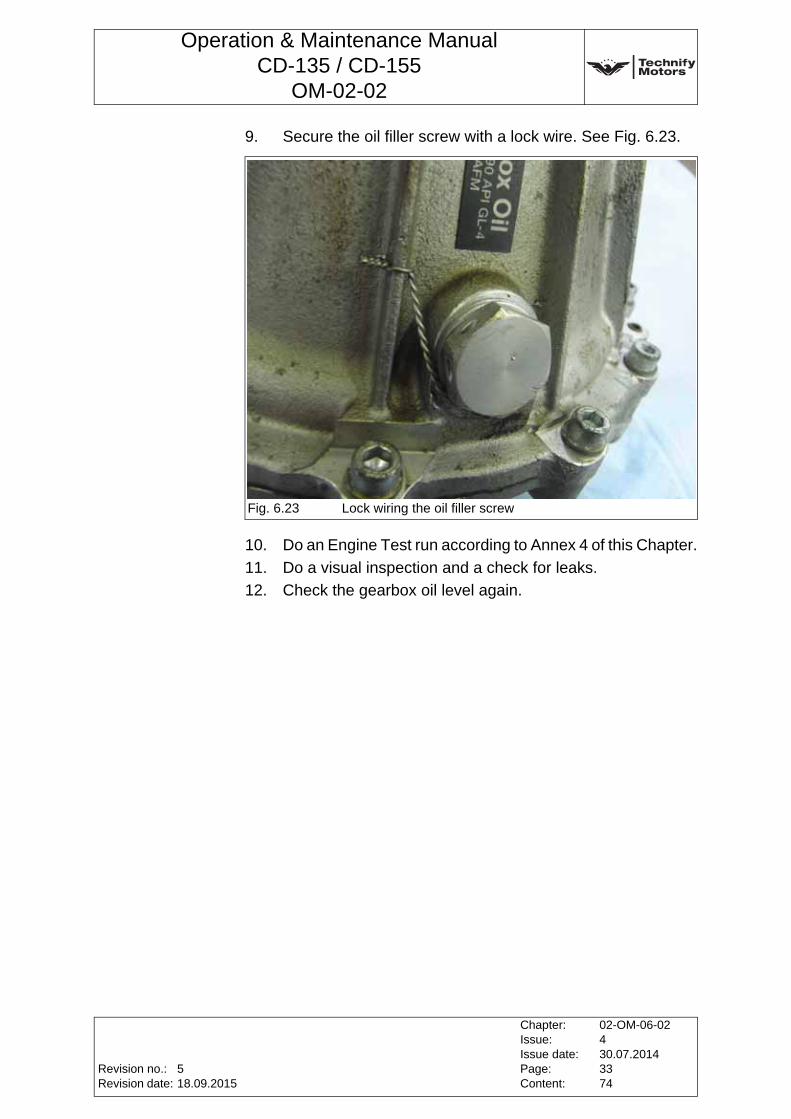
Operation & Maintenance ManualCD-135 / CD-155
OM-02-02
9. Secure the oil filler screw with a lock wire. See Fig. 6.23.
10. Do an Engine Test run according to Annex 4 of this Chapter.
11. Do a visual inspection and a check for leaks.
12. Check the gearbox oil level again.
Fig. 6.23 Lock wiring the oil filler screw
Revision no.:Revision date:
Chapter:Issue:Issue date:Page:Content:
02-OM-06-02430.07.20143374
518.09.2015
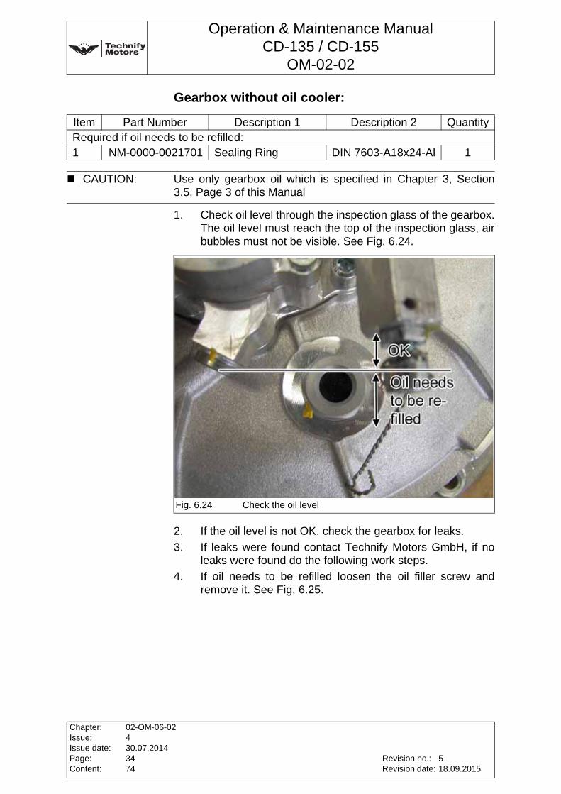
Operation & Maintenance ManualCD-135 / CD-155
OM-02-02
Gearbox without oil cooler:
1. Check oil level through the inspection glass of the gearbox. The oil level must reach the top of the inspection glass, air bubbles must not be visible. See Fig. 6.24.
2. If the oil level is not OK, check the gearbox for leaks.
3. If leaks were found contact Technify Motors GmbH, if no leaks were found do the following work steps.
4. If oil needs to be refilled loosen the oil filler screw and remove it. See Fig. 6.25.
Item Part Number Description 1 Description 2 QuantityRequired if oil needs to be refilled:1 NM-0000-0021701 Sealing Ring DIN 7603-A18x24-Al 1
CAUTION: Use only gearbox oil which is specified in Chapter 3, Section 3.5, Page 3 of this Manual
Fig. 6.24 Check the oil level
Chapter:Issue:Issue date:Page:Content:
02-OM-06-02430.07.20143474
Revision no.:Revision date:
518.09.2015
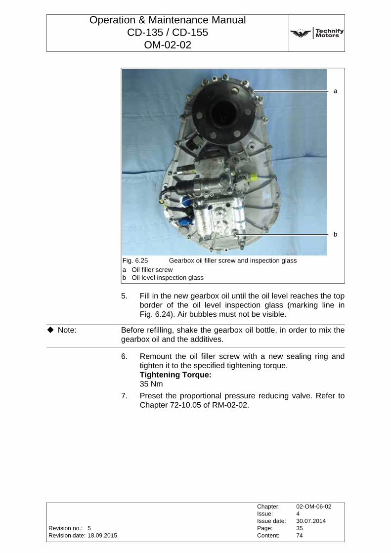
Operation & Maintenance ManualCD-135 / CD-155
OM-02-02
5. Fill in the new gearbox oil until the oil level reaches the top border of the oil level inspection glass (marking line in Fig. 6.24). Air bubbles must not be visible.
6. Remount the oil filler screw with a new sealing ring and tighten it to the specified tightening torque.Tightening Torque:35 Nm
7. Preset the proportional pressure reducing valve. Refer to Chapter 72-10.05 of RM-02-02.
Fig. 6.25 Gearbox oil filler screw and inspection glass
a Oil filler screwb Oil level inspection glass
a
b
Note: Before refilling, shake the gearbox oil bottle, in order to mix the gearbox oil and the additives.
Revision no.:Revision date:
Chapter:Issue:Issue date:Page:Content:
02-OM-06-02430.07.20143574
518.09.2015
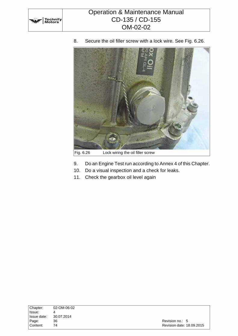
Operation & Maintenance ManualCD-135 / CD-155
OM-02-02
8. Secure the oil filler screw with a lock wire. See Fig. 6.26.
9. Do an Engine Test run according to Annex 4 of this Chapter.
10. Do a visual inspection and a check for leaks.
11. Check the gearbox oil level again
Fig. 6.26 Lock wiring the oil filler screw
Chapter:Issue:Issue date:Page:Content:
02-OM-06-02430.07.20143674
Revision no.:Revision date:
518.09.2015
Operation & Maintenance ManualCD-135 / CD-155
OM-02-02
Annex 10 FADEC Read-out1. General
The FADEC service tool is designed to provide the user access to Real time data, the onboard logger system as well as the event log information available from the Technify Motors GmbH FADEC system, and to facilitate organizing the data and to send this data to Technify Motors GmbH.The tool is a requirement for standard maintenance as well as troubleshooting of the powerplant. This document provides instructions for using the software. Consult the operation & maintenance manual, the fault isolation manual as well as other available documentation for instructions and limitations of operation, maintenance, repair and troubleshooting. Routine maintenance must consist of a regular maintenance download and include:
• Event Log (FADEC DATA)
• Real Time Log File from Ground Run(refer to Chapter 4, Section 4.4.2, Page 5 of this Manual for ground run procedures and requirements)
and shall be sent to:[email protected]
Request for diagnosis must consist of an extended download and must include all of the above plus
• download of the onboard logger (both ECUs),
• a detailed description of the abnormality.and shall be sent to [email protected]
The software tool is capable of providing the appropriate download in a single operation to reduce time and effort spent by the user. Please proceed to section 4 or 5 of this annex, as appropriate to perform a regular maintenance or an extended download.
Revision no.:Revision date:
Chapter:Issue:Issue date:Page:Content:
02-OM-06-02430.07.20143774
518.09.2015
Operation & Maintenance ManualCD-135 / CD-155
OM-02-02
2. Viewing the Event Log
The event log may be viewed without generating a file. For data to be sent to Technify Motors GmbH, the complete download appropriate to the situation should be used. Refer to section 4 and 5.
a) Establish CAN communication, by connecting the computer to the aircraft, starting the program and powering up the FADEC.
b) Menu FADEC => Show Event Log
Note: Please use a compressed file format such as .zip to send any data. This greatly reduces transfer times and facilitates data handling on both sides. The tool offers this function automatically for the regular maintenance download and the extended download. After completing the download (maintenance or extended), the folder for the desired engine will contain a compressed file including all relevant data. Please send only one compressed file containing all the appropriate data for the event.
Note: The Tool gives the user the capability to view the eventlog separately. This is not generally necessary, as the tool provides all necessary files in a single download. Please proceed to section 4 or 5 of this annex as appropriate.
Chapter:Issue:Issue date:Page:Content:
02-OM-06-02430.07.20143874
Revision no.:Revision date:
518.09.2015
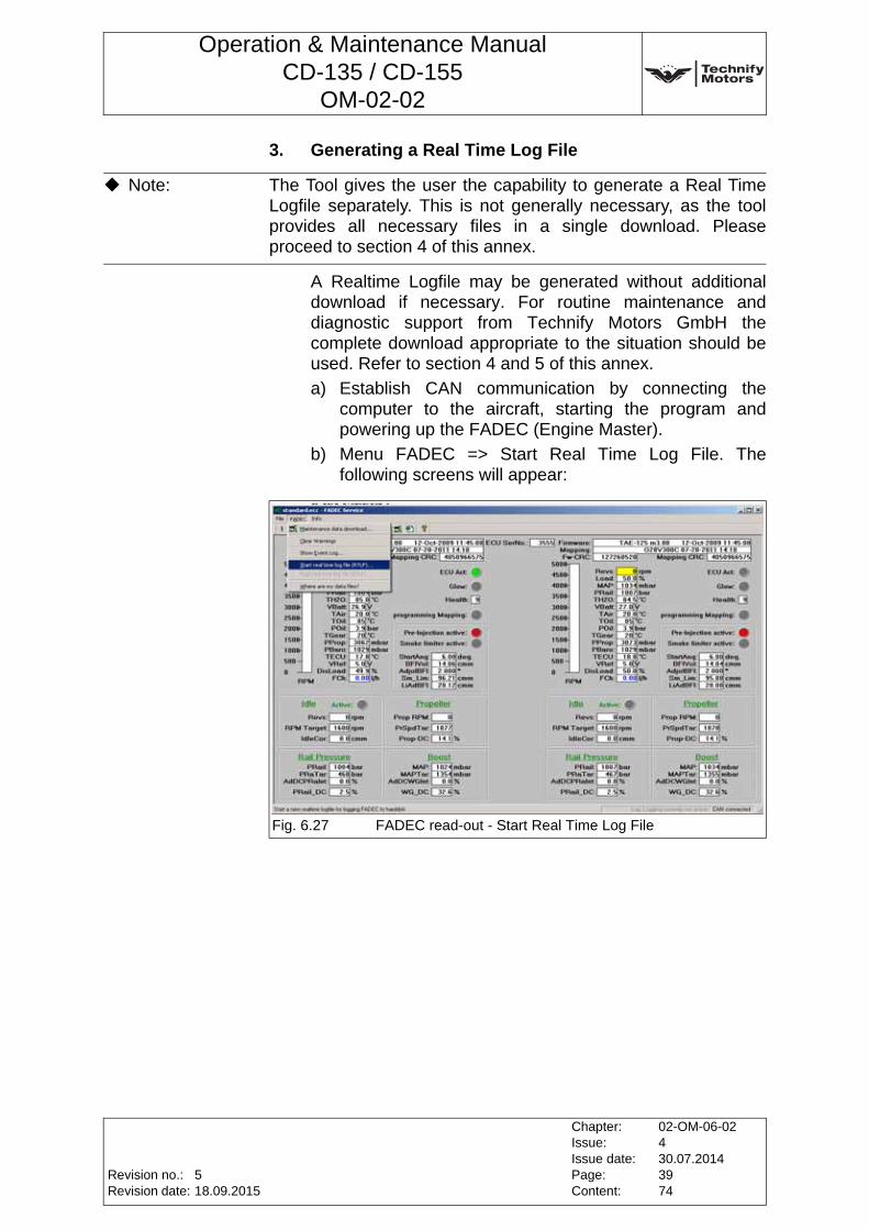
Operation & Maintenance ManualCD-135 / CD-155
OM-02-02
3. Generating a Real Time Log File
A Realtime Logfile may be generated without additional download if necessary. For routine maintenance and diagnostic support from Technify Motors GmbH the complete download appropriate to the situation should be used. Refer to section 4 and 5 of this annex.
a) Establish CAN communication by connecting the computer to the aircraft, starting the program and powering up the FADEC (Engine Master).
b) Menu FADEC => Start Real Time Log File. The following screens will appear:
Note: The Tool gives the user the capability to generate a Real Time Logfile separately. This is not generally necessary, as the tool provides all necessary files in a single download. Please proceed to section 4 of this annex.
Fig. 6.27 FADEC read-out - Start Real Time Log File
Revision no.:Revision date:
Chapter:Issue:Issue date:Page:Content:
02-OM-06-02430.07.20143974
518.09.2015
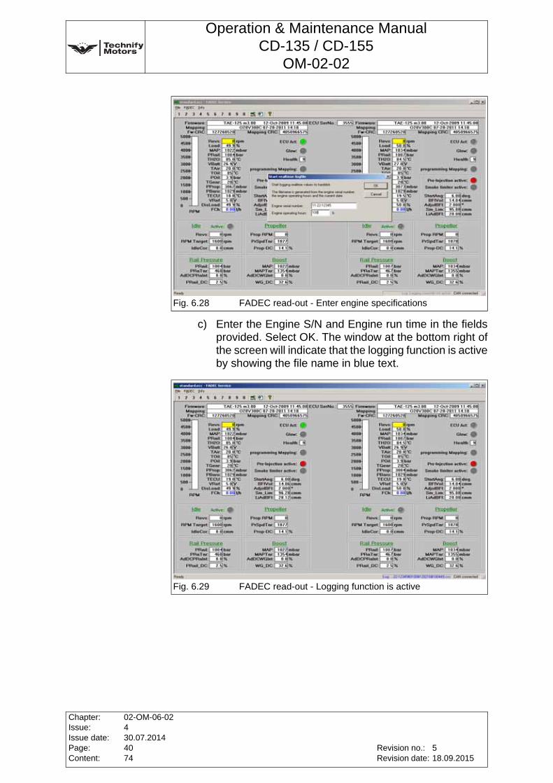
Operation & Maintenance ManualCD-135 / CD-155
OM-02-02
c) Enter the Engine S/N and Engine run time in the fields provided. Select OK. The window at the bottom right of the screen will indicate that the logging function is active by showing the file name in blue text.
Fig. 6.28 FADEC read-out - Enter engine specifications
Fig. 6.29 FADEC read-out - Logging function is active
Chapter:Issue:Issue date:Page:Content:
02-OM-06-02430.07.20144074
Revision no.:Revision date:
518.09.2015
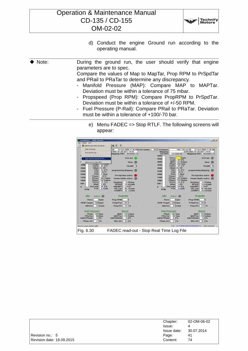
Operation & Maintenance ManualCD-135 / CD-155
OM-02-02
d) Conduct the engine Ground run according to the operating manual.
e) Menu FADEC => Stop RTLF. The following screens will appear:
Note: During the ground run, the user should verify that engine parameters are to spec. Compare the values of Map to MapTar, Prop RPM to PrSpdTar and PRail to PRaTar to determine any discrepancy.- Manifold Pressure (MAP): Compare MAP to MAPTar.
Deviation must be within a tolerance of 75 mbar.- Propspeed (Prop RPM): Compare PropRPM to PrSpdTar.
Deviation must be within a tolerance of +/-50 RPM.- Fuel Pressure (P-Rail): Compare PRail to PRaTar. Deviation
must be within a tolerance of +100/-70 bar.
Fig. 6.30 FADEC read-out - Stop Real Time Log File
Revision no.:Revision date:
Chapter:Issue:Issue date:Page:Content:
02-OM-06-02430.07.20144174
518.09.2015
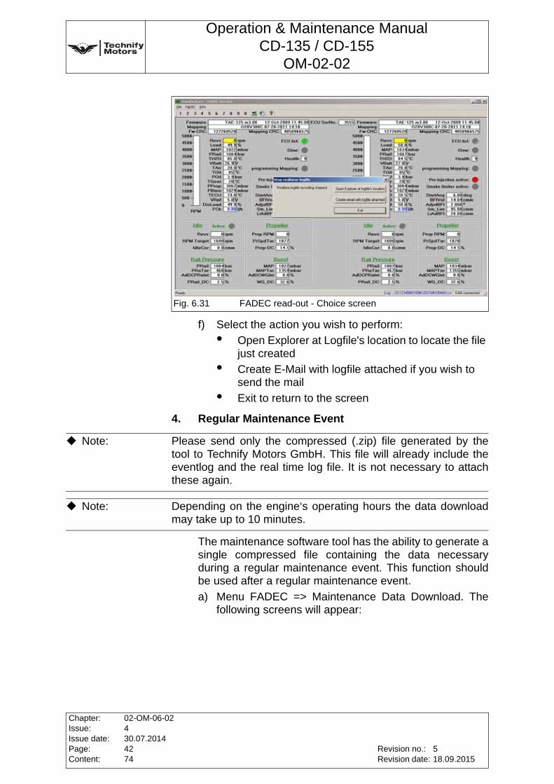
Operation & Maintenance ManualCD-135 / CD-155
OM-02-02
f) Select the action you wish to perform:
• Open Explorer at Logfile's location to locate the file just created
• Create E-Mail with logfile attached if you wish to send the mail
• Exit to return to the screen
4. Regular Maintenance Event
The maintenance software tool has the ability to generate a single compressed file containing the data necessary during a regular maintenance event. This function should be used after a regular maintenance event.
a) Menu FADEC => Maintenance Data Download. The following screens will appear:
Fig. 6.31 FADEC read-out - Choice screen
Note: Please send only the compressed (.zip) file generated by the tool to Technify Motors GmbH. This file will already include the eventlog and the real time log file. It is not necessary to attach these again.
Note: Depending on the engine‘s operating hours the data download may take up to 10 minutes.
Chapter:Issue:Issue date:Page:Content:
02-OM-06-02430.07.20144274
Revision no.:Revision date:
518.09.2015
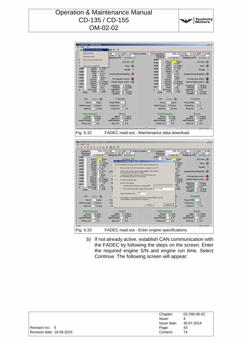
Operation & Maintenance ManualCD-135 / CD-155
OM-02-02
b) If not already active, establish CAN communication with the FADEC by following the steps on the screen. Enter the required engine S/N and engine run time. Select Continue. The following screen will appear:
Fig. 6.32 FADEC read-out - Maintenance data download
Fig. 6.33 FADEC read-out - Enter engine specifications
Revision no.:Revision date:
Chapter:Issue:Issue date:Page:Content:
02-OM-06-02430.07.20144374
518.09.2015
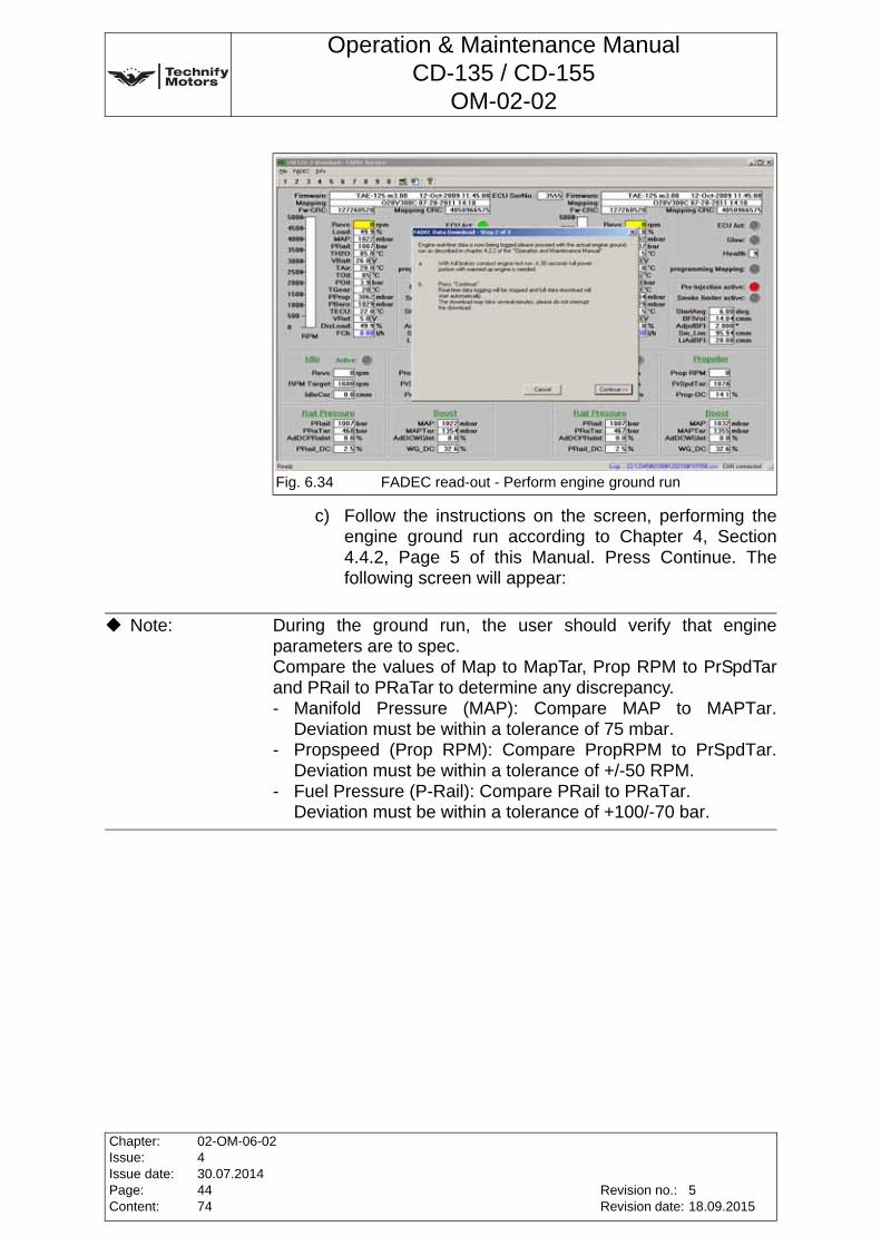
Operation & Maintenance ManualCD-135 / CD-155
OM-02-02
c) Follow the instructions on the screen, performing the engine ground run according to Chapter 4, Section 4.4.2, Page 5 of this Manual. Press Continue. The following screen will appear:
Fig. 6.34 FADEC read-out - Perform engine ground run
Note: During the ground run, the user should verify that engine parameters are to spec. Compare the values of Map to MapTar, Prop RPM to PrSpdTar and PRail to PRaTar to determine any discrepancy.- Manifold Pressure (MAP): Compare MAP to MAPTar.
Deviation must be within a tolerance of 75 mbar.- Propspeed (Prop RPM): Compare PropRPM to PrSpdTar.
Deviation must be within a tolerance of +/-50 RPM.- Fuel Pressure (P-Rail): Compare PRail to PRaTar.
Deviation must be within a tolerance of +100/-70 bar.
Chapter:Issue:Issue date:Page:Content:
02-OM-06-02430.07.20144474
Revision no.:Revision date:
518.09.2015
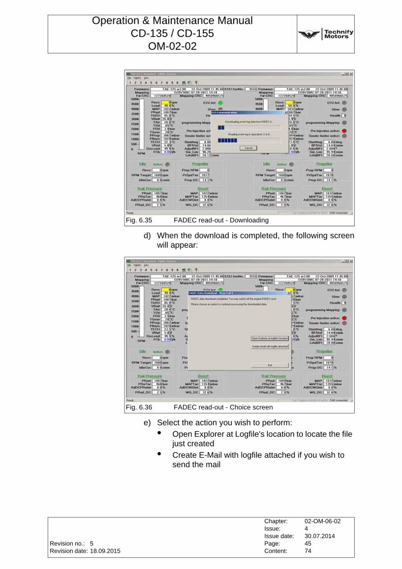
Operation & Maintenance ManualCD-135 / CD-155
OM-02-02
d) When the download is completed, the following screen will appear:
e) Select the action you wish to perform:
• Open Explorer at Logfile's location to locate the file just created
• Create E-Mail with logfile attached if you wish to send the mail
Fig. 6.35 FADEC read-out - Downloading
Fig. 6.36 FADEC read-out - Choice screen
Revision no.:Revision date:
Chapter:Issue:Issue date:Page:Content:
02-OM-06-02430.07.20144574
518.09.2015
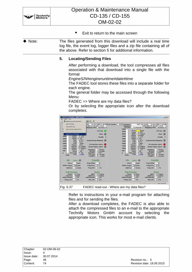
Operation & Maintenance ManualCD-135 / CD-155
OM-02-02
• Exit to return to the main screen
5. Locating/Sending Files
After performing a download, the tool compresses all files associated with that download into a single file with the format EngineS/N#engineruntime#date#time The FADEC tool stores these files into a separate folder for each engine. The general folder may be accessed through the following Menu: FADEC => Where are my data files? Or by selecting the appropriate icon after the download completes.
Refer to instructions in your e-mail program for attaching files and for sending the files. After a download completes, the FADEC is also able to attach the compressed files to an e-mail to the appropriate Technify Motors GmbH account by selecting the appropriate icon. This works for most e-mail clients.
Note: The files generated from this download will include a real time log file, the event log, logger files and a zip file containing all of the above. Refer to section 5 for additional information.
Fig. 6.37 FADEC read-out - Where are my data files?
Chapter:Issue:Issue date:Page:Content:
02-OM-06-02430.07.20144674
Revision no.:Revision date:
518.09.2015
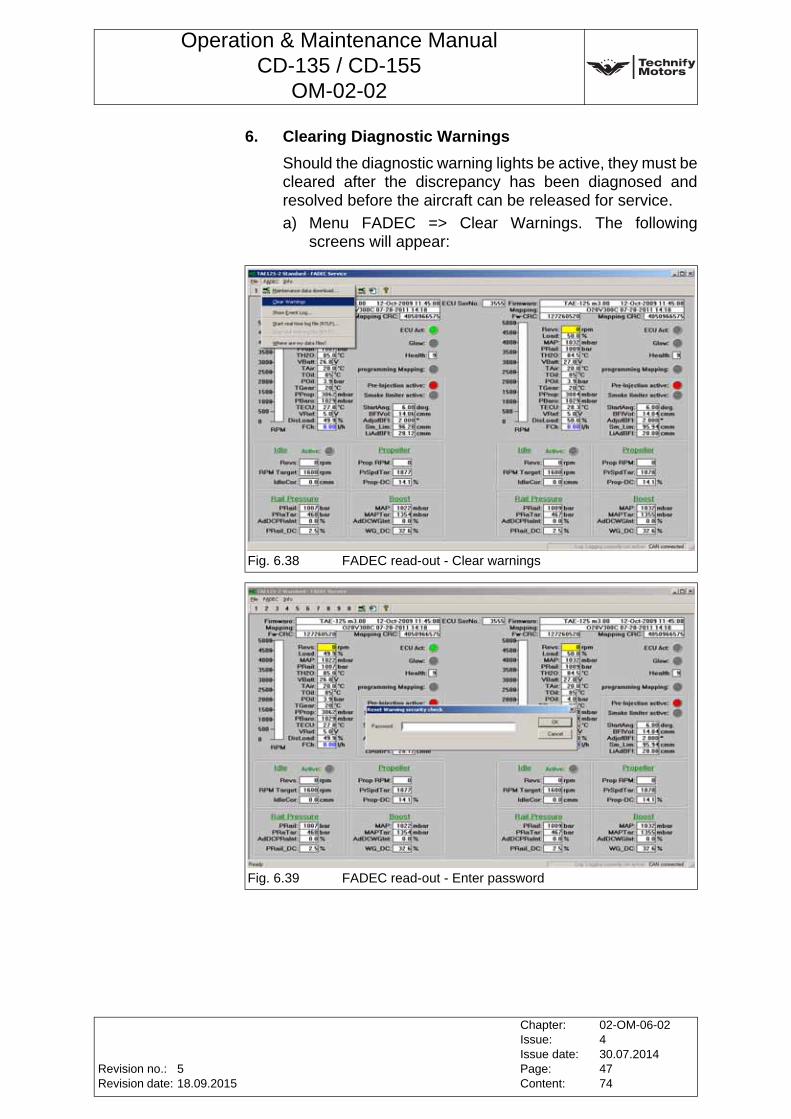
Operation & Maintenance ManualCD-135 / CD-155
OM-02-02
6. Clearing Diagnostic Warnings
Should the diagnostic warning lights be active, they must be cleared after the discrepancy has been diagnosed and resolved before the aircraft can be released for service.
a) Menu FADEC => Clear Warnings. The following screens will appear:
Fig. 6.38 FADEC read-out - Clear warnings
Fig. 6.39 FADEC read-out - Enter password
Revision no.:Revision date:
Chapter:Issue:Issue date:Page:Content:
02-OM-06-02430.07.20144774
518.09.2015
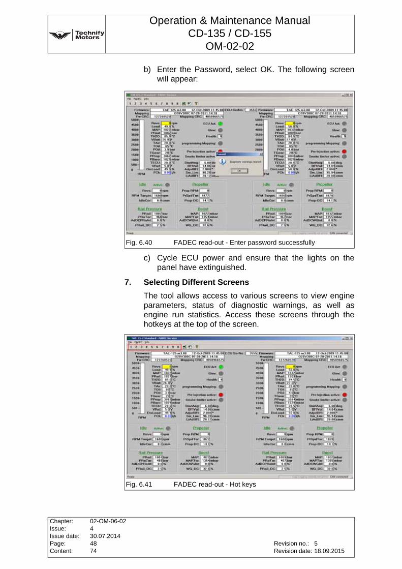
Operation & Maintenance ManualCD-135 / CD-155
OM-02-02
b) Enter the Password, select OK. The following screen will appear:
c) Cycle ECU power and ensure that the lights on the panel have extinguished.
7. Selecting Different Screens
The tool allows access to various screens to view engine parameters, status of diagnostic warnings, as well as engine run statistics. Access these screens through the hotkeys at the top of the screen.
Fig. 6.40 FADEC read-out - Enter password successfully
Fig. 6.41 FADEC read-out - Hot keys
Chapter:Issue:Issue date:Page:Content:
02-OM-06-02430.07.20144874
Revision no.:Revision date:
518.09.2015
Operation & Maintenance ManualCD-135 / CD-155
OM-02-02
Annex 11 Inspecting the High-Pressure PumpThe high-pressure pump must be delivered to Technify Motors GmbH for maintenance. To remove and install the high-pressure pump, refer to RM-02-02.
Revision no.:Revision date:
Chapter:Issue:Issue date:Page:Content:
02-OM-06-02430.07.20144974
518.09.2015
Operation & Maintenance ManualCD-135 / CD-155
OM-02-02
Annex 12 Replacing the AlternatorThe alternator must be delivered to Technify Motors GmbH for maintenance. To remove and install the alternator, refer to RM-02-02.
Chapter:Issue:Issue date:Page:Content:
02-OM-06-02430.07.20145074
Revision no.:Revision date:
518.09.2015
Operation & Maintenance ManualCD-135 / CD-155
OM-02-02
Annex 13 Exchanging the gearbox oil and the gearbox oil filter at the gearbox
Gearbox with oil cooler:
1. Warm up the engine until the gearbox oil has a temperature of 50°C.
2. Loosen the oil drain plug of the gearbox. Catch the oil with an appropriate container. See Fig. 6.42.
Item Part Number Description 1 Description 2 Quantity1 03-7212-K004001 Filter element 1
3 NM-0000-0150401 O-RingDIN 3771-25x2,5-80FKM610
1
5 NM-0000-0021701 Sealing Ring DIN 7603-A18x24-Al 16 NM-0000-0188601 Sealing Ring 18x24x1,5-Viton 80 1
CAUTION: The regulations regarding the disposal of waste oil must be observed. Never discharge waste oil into the sewage system or the ground.
CAUTION: Only use an original Technify Motors GmbH gearbox oil filter. Use only gearbox oil which is specified in Chapter 3, Section 3.5, Page 3 of this Manual.
CAUTION: The regulations regarding the disposal of waste oil must be observed. Never discharge waste oil into the sewage system or the ground.
Note: Fill 100ml of the used gearbox oil in a clean container and put a label on the container. This oil-sample must be made available to Technify Motors GmbH on request for the complete engine life time. The label must show the aircraft serial number, registration number, engine serial number, operation time and the date.
Revision no.:Revision date:
Chapter:Issue:Issue date:Page:Content:
02-OM-06-02430.07.20145174
518.09.2015
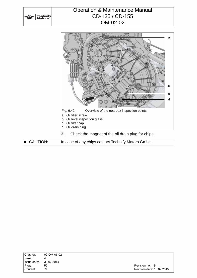
Operation & Maintenance ManualCD-135 / CD-155
OM-02-02
3. Check the magnet of the oil drain plug for chips.
Fig. 6.42 Overview of the gearbox inspection points
a Oil filler screwb Oil level inspection glassc Oil filter capd Oil drain plug
a
b
c
d
CAUTION: In case of any chips contact Technify Motors GmbH.
Chapter:Issue:Issue date:Page:Content:
02-OM-06-02430.07.20145274
Revision no.:Revision date:
518.09.2015
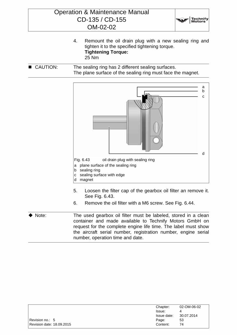
Operation & Maintenance ManualCD-135 / CD-155
OM-02-02
4. Remount the oil drain plug with a new sealing ring and tighten it to the specified tightening torque.Tightening Torque:25 Nm
5. Loosen the filter cap of the gearbox oil filter an remove it. See Fig. 6.43.
6. Remove the oil filter with a M6 screw. See Fig. 6.44.
CAUTION: The sealing ring has 2 different sealing surfaces.The plane surface of the sealing ring must face the magnet.
Fig. 6.43 oil drain plug with sealing ring
a plane surface of the sealing ringb sealing ringc sealing surface with edged magnet
abc
d
Note: The used gearbox oil filter must be labeled, stored in a clean container and made available to Technify Motors GmbH on request for the complete engine life time. The label must show the aircraft serial number, registration number, engine serial number, operation time and date.
Revision no.:Revision date:
Chapter:Issue:Issue date:Page:Content:
02-OM-06-02430.07.20145374
518.09.2015
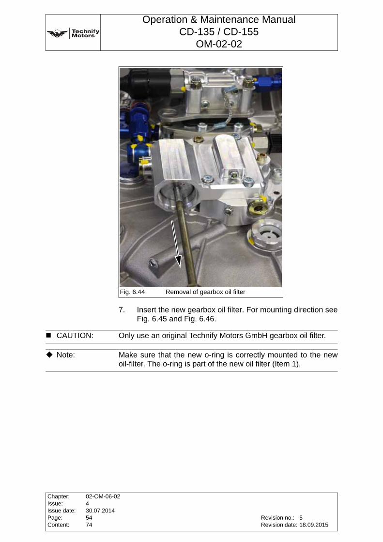
Operation & Maintenance ManualCD-135 / CD-155
OM-02-02
7. Insert the new gearbox oil filter. For mounting direction see Fig. 6.45 and Fig. 6.46.
Fig. 6.44 Removal of gearbox oil filter
CAUTION: Only use an original Technify Motors GmbH gearbox oil filter.
Note: Make sure that the new o-ring is correctly mounted to the new oil-filter. The o-ring is part of the new oil filter (Item 1).
Chapter:Issue:Issue date:Page:Content:
02-OM-06-02430.07.20145474
Revision no.:Revision date:
518.09.2015
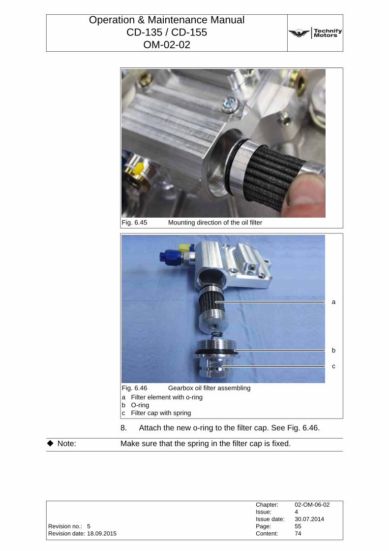
Operation & Maintenance ManualCD-135 / CD-155
OM-02-02
8. Attach the new o-ring to the filter cap. See Fig. 6.46.
Fig. 6.45 Mounting direction of the oil filter
Fig. 6.46 Gearbox oil filter assembling
a Filter element with o-ringb O-ringc Filter cap with spring
a
b
c
Note: Make sure that the spring in the filter cap is fixed.
Revision no.:Revision date:
Chapter:Issue:Issue date:Page:Content:
02-OM-06-02430.07.20145574
518.09.2015
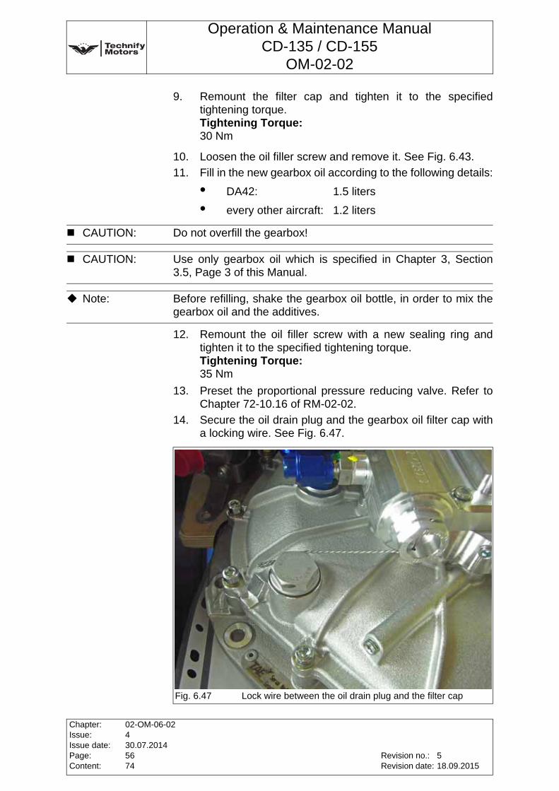
Operation & Maintenance ManualCD-135 / CD-155
OM-02-02
9. Remount the filter cap and tighten it to the specified tightening torque.Tightening Torque:30 Nm
10. Loosen the oil filler screw and remove it. See Fig. 6.43.
11. Fill in the new gearbox oil according to the following details:
• DA42: 1.5 liters
• every other aircraft: 1.2 liters
12. Remount the oil filler screw with a new sealing ring and tighten it to the specified tightening torque.Tightening Torque:35 Nm
13. Preset the proportional pressure reducing valve. Refer to Chapter 72-10.16 of RM-02-02.
14. Secure the oil drain plug and the gearbox oil filter cap with a locking wire. See Fig. 6.47.
CAUTION: Do not overfill the gearbox!
CAUTION: Use only gearbox oil which is specified in Chapter 3, Section 3.5, Page 3 of this Manual.
Note: Before refilling, shake the gearbox oil bottle, in order to mix the gearbox oil and the additives.
Fig. 6.47 Lock wire between the oil drain plug and the filter cap
Chapter:Issue:Issue date:Page:Content:
02-OM-06-02430.07.20145674
Revision no.:Revision date:
518.09.2015

Operation & Maintenance ManualCD-135 / CD-155
OM-02-02
15. Secure the oil filler screw with a lock wire. See Fig. 6.48.
16. Do an Engine Test run according Annex 4 of this Chapter.
17. Do a visual inspection and a check for leaks.
18. Check the gearbox oil level according to Annex 9 of this Chapter.
Fig. 6.48 Lock wiring the oil filler screw
Revision no.:Revision date:
Chapter:Issue:Issue date:Page:Content:
02-OM-06-02430.07.20145774
518.09.2015
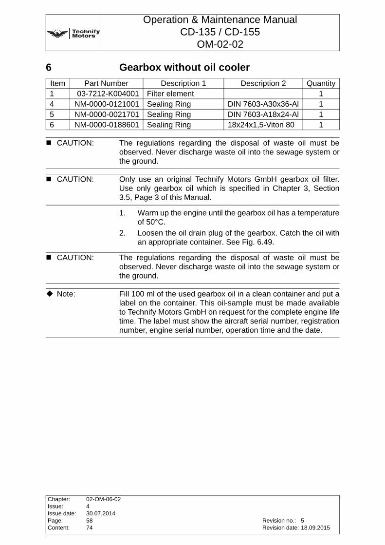
Operation & Maintenance ManualCD-135 / CD-155
OM-02-02
6 Gearbox without oil cooler
1. Warm up the engine until the gearbox oil has a temperature of 50°C.
2. Loosen the oil drain plug of the gearbox. Catch the oil with an appropriate container. See Fig. 6.49.
Item Part Number Description 1 Description 2 Quantity1 03-7212-K004001 Filter element 14 NM-0000-0121001 Sealing Ring DIN 7603-A30x36-Al 15 NM-0000-0021701 Sealing Ring DIN 7603-A18x24-Al 16 NM-0000-0188601 Sealing Ring 18x24x1,5-Viton 80 1
CAUTION: The regulations regarding the disposal of waste oil must be observed. Never discharge waste oil into the sewage system or the ground.
CAUTION: Only use an original Technify Motors GmbH gearbox oil filter. Use only gearbox oil which is specified in Chapter 3, Section 3.5, Page 3 of this Manual.
CAUTION: The regulations regarding the disposal of waste oil must be observed. Never discharge waste oil into the sewage system or the ground.
Note: Fill 100 ml of the used gearbox oil in a clean container and put a label on the container. This oil-sample must be made available to Technify Motors GmbH on request for the complete engine life time. The label must show the aircraft serial number, registration number, engine serial number, operation time and the date.
Chapter:Issue:Issue date:Page:Content:
02-OM-06-02430.07.20145874
Revision no.:Revision date:
518.09.2015
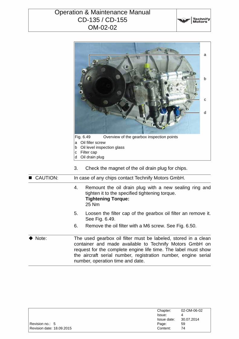
Operation & Maintenance ManualCD-135 / CD-155
OM-02-02
3. Check the magnet of the oil drain plug for chips.
4. Remount the oil drain plug with a new sealing ring and tighten it to the specified tightening torque.Tightening Torque:25 Nm
5. Loosen the filter cap of the gearbox oil filter an remove it. See Fig. 6.49.
6. Remove the oil filter with a M6 screw. See Fig. 6.50.
Fig. 6.49 Overview of the gearbox inspection points
a Oil filler screwb Oil level inspection glassc Filter capd Oil drain plug
a
b
c
d
CAUTION: In case of any chips contact Technify Motors GmbH.
Note: The used gearbox oil filter must be labeled, stored in a clean container and made available to Technify Motors GmbH on request for the complete engine life time. The label must show the aircraft serial number, registration number, engine serial number, operation time and date.
Revision no.:Revision date:
Chapter:Issue:Issue date:Page:Content:
02-OM-06-02430.07.20145974
518.09.2015
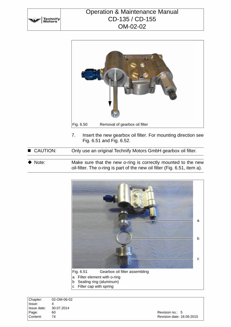
Operation & Maintenance ManualCD-135 / CD-155
OM-02-02
7. Insert the new gearbox oil filter. For mounting direction see Fig. 6.51 and Fig. 6.52.
Fig. 6.50 Removal of gearbox oil filter
CAUTION: Only use an original Technify Motors GmbH gearbox oil filter.
Note: Make sure that the new o-ring is correctly mounted to the new oil-filter. The o-ring is part of the new oil filter (Fig. 6.51, item a).
Fig. 6.51 Gearbox oil filter assembling
a Filter element with o-ringb Sealing ring (aluminum)c Filter cap with spring
a
b
c
Chapter:Issue:Issue date:Page:Content:
02-OM-06-02430.07.20146074
Revision no.:Revision date:
518.09.2015
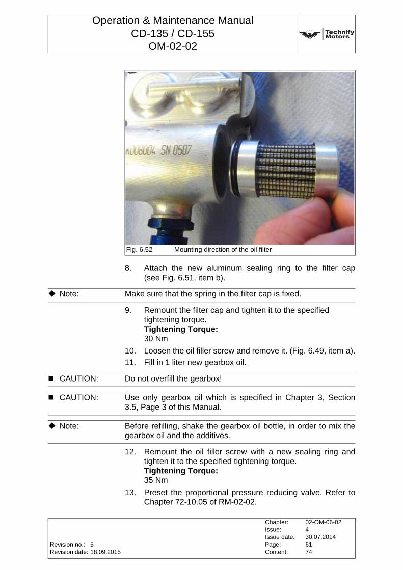
Operation & Maintenance ManualCD-135 / CD-155
OM-02-02
8. Attach the new aluminum sealing ring to the filter cap (see Fig. 6.51, item b).
9. Remount the filter cap and tighten it to the specified tightening torque.Tightening Torque:30 Nm
10. Loosen the oil filler screw and remove it. (Fig. 6.49, item a).
11. Fill in 1 liter new gearbox oil.
12. Remount the oil filler screw with a new sealing ring and tighten it to the specified tightening torque.Tightening Torque:35 Nm
13. Preset the proportional pressure reducing valve. Refer to Chapter 72-10.05 of RM-02-02.
Fig. 6.52 Mounting direction of the oil filter
Note: Make sure that the spring in the filter cap is fixed.
CAUTION: Do not overfill the gearbox!
CAUTION: Use only gearbox oil which is specified in Chapter 3, Section 3.5, Page 3 of this Manual.
Note: Before refilling, shake the gearbox oil bottle, in order to mix the gearbox oil and the additives.
Revision no.:Revision date:
Chapter:Issue:Issue date:Page:Content:
02-OM-06-02430.07.20146174
518.09.2015
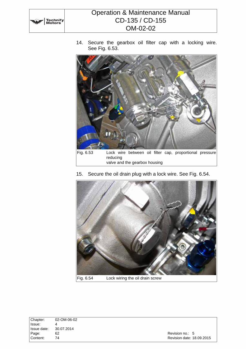
Operation & Maintenance ManualCD-135 / CD-155
OM-02-02
14. Secure the gearbox oil filter cap with a locking wire. See Fig. 6.53.
15. Secure the oil drain plug with a lock wire. See Fig. 6.54.
Fig. 6.53 Lock wire between oil filter cap, proportional pressure reducingvalve and the gearbox housing
Fig. 6.54 Lock wiring the oil drain screw
Chapter:Issue:Issue date:Page:Content:
02-OM-06-02430.07.20146274
Revision no.:Revision date:
518.09.2015
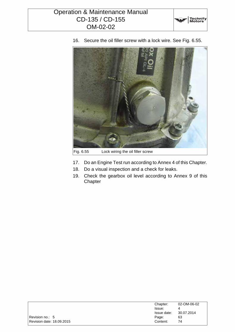
Operation & Maintenance ManualCD-135 / CD-155
OM-02-02
16. Secure the oil filler screw with a lock wire. See Fig. 6.55.
17. Do an Engine Test run according to Annex 4 of this Chapter.
18. Do a visual inspection and a check for leaks.
19. Check the gearbox oil level according to Annex 9 of this Chapter
Fig. 6.55 Lock wiring the oil filler screw
Revision no.:Revision date:
Chapter:Issue:Issue date:Page:Content:
02-OM-06-02430.07.20146374
518.09.2015
Operation & Maintenance ManualCD-135 / CD-155
OM-02-02
Annex 14 Exchanging the Coolant
1. Draining the coolant:
• Open the clamp on the lower hose of the water radiator, disconnect the hose and allow the coolant to drain into a prepared collecting container.
• Open the clamp on the lower hose of the heat exchanger, disconnect the hose and allow the coolant to drain into a collection container.
• Open the drain plug. Allow the coolant to drain into a collection container.
• After draining reinstall and tighten the drain plug.Tightening Torque:30 Nm
• Reconnect the lower hoses of the water radiator and the heat exchanger. Tighten the clamps.
2. Filling up new coolant:
• Fill up the cooling system with coolant according toIM-02-02 Chapter 4 by opening the coolant filler.
• Close the cover of the coolant filler.
• Perform a test run according toChapter 4, Section 4.4.2, Page 5 of this Manual.
• Check the cooling system for leaks according to Annex 3 of this Chapter.
• Allow the engine to cool down.
• Check coolant level.
WARNING: Risk of scalding! The cooling system may be pressurized. Carefully release the pressure before opening the drain plug.
CAUTION: Do not drain the coolant if its temperature is above 40°C.
Chapter:Issue:Issue date:Page:Content:
02-OM-06-02430.07.20146474
Revision no.:Revision date:
518.09.2015
Operation & Maintenance ManualCD-135 / CD-155
OM-02-02
Annex 15 Inspecting the GearboxThe gearbox must be delivered to Technify Motors GmbH for inspection. To remove and install the gearbox, refer to RM-02-02.
Revision no.:Revision date:
Chapter:Issue:Issue date:Page:Content:
02-OM-06-02430.07.20146574
518.09.2015
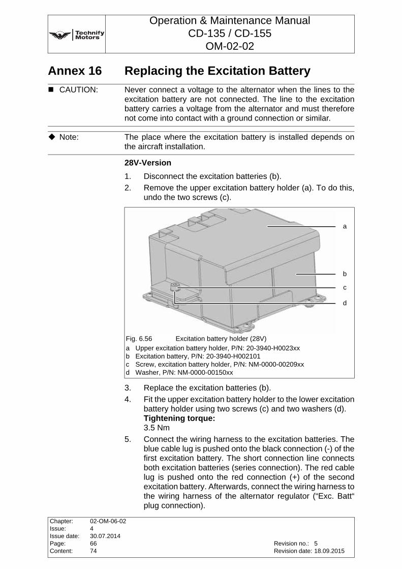
Operation & Maintenance ManualCD-135 / CD-155
OM-02-02
Annex 16 Replacing the Excitation Battery
28V-Version
1. Disconnect the excitation batteries (b).
2. Remove the upper excitation battery holder (a). To do this, undo the two screws (c).
3. Replace the excitation batteries (b).
4. Fit the upper excitation battery holder to the lower excitation battery holder using two screws (c) and two washers (d).Tightening torque:3.5 Nm
5. Connect the wiring harness to the excitation batteries. The blue cable lug is pushed onto the black connection (-) of the first excitation battery. The short connection line connects both excitation batteries (series connection). The red cable lug is pushed onto the red connection (+) of the second excitation battery. Afterwards, connect the wiring harness to the wiring harness of the alternator regulator (“Exc. Batt“ plug connection).
CAUTION: Never connect a voltage to the alternator when the lines to the excitation battery are not connected. The line to the excitation battery carries a voltage from the alternator and must therefore not come into contact with a ground connection or similar.
Note: The place where the excitation battery is installed depends on the aircraft installation.
Fig. 6.56 Excitation battery holder (28V)
a Upper excitation battery holder, P/N: 20-3940-H0023xxb Excitation battery, P/N: 20-3940-H002101c Screw, excitation battery holder, P/N: NM-0000-00209xxd Washer, P/N: NM-0000-00150xx
a
b
c
d
Chapter:Issue:Issue date:Page:Content:
02-OM-06-02430.07.20146674
Revision no.:Revision date:
518.09.2015
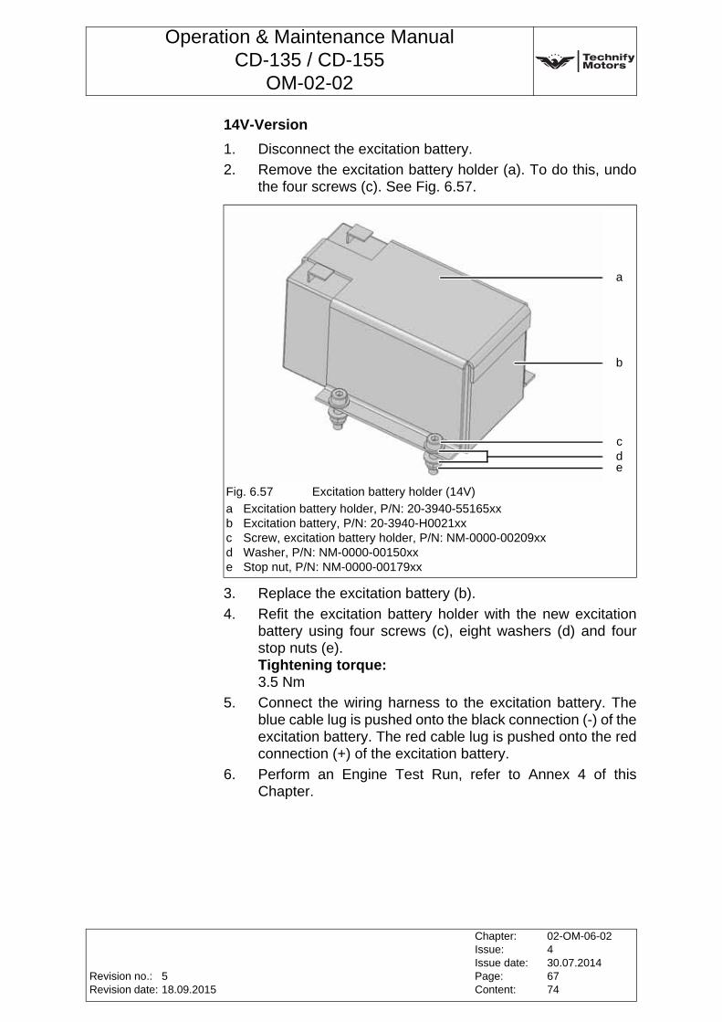
Operation & Maintenance ManualCD-135 / CD-155
OM-02-02
14V-Version
1. Disconnect the excitation battery.
2. Remove the excitation battery holder (a). To do this, undo the four screws (c). See Fig. 6.57.
3. Replace the excitation battery (b).
4. Refit the excitation battery holder with the new excitation battery using four screws (c), eight washers (d) and four stop nuts (e).Tightening torque:3.5 Nm
5. Connect the wiring harness to the excitation battery. The blue cable lug is pushed onto the black connection (-) of the excitation battery. The red cable lug is pushed onto the red connection (+) of the excitation battery.
6. Perform an Engine Test Run, refer to Annex 4 of this Chapter.
Fig. 6.57 Excitation battery holder (14V)
a Excitation battery holder, P/N: 20-3940-55165xxb Excitation battery, P/N: 20-3940-H0021xxc Screw, excitation battery holder, P/N: NM-0000-00209xxd Washer, P/N: NM-0000-00150xxe Stop nut, P/N: NM-0000-00179xx
a
b
cde
Revision no.:Revision date:
Chapter:Issue:Issue date:Page:Content:
02-OM-06-02430.07.20146774
518.09.2015
Operation & Maintenance ManualCD-135 / CD-155
OM-02-02
Annex 17 FADEC Software Update
Hardware RequirementsThis software has been designed for Microsoft Windows 2000/XP/Vista. For proper functionality, the Microsoft .Net framework version 3.5 or newer is required (Windows Vista already contains this). If you don‘t have a proper .NET version installed, please download the framework at www.microsoft.com/net.
Installation and De-installation1. Please start installation of the software by double-clicking
the setup file that you have received.
2. Follow the instructions given to you during the process. Afterwards, you can start the program by using the link on your computer‘s desktop.
Update Process1. For updating FADEC software, please attach the USB CAN
interface to the FADEC and your computer.
2. Battery switch - „ON“
3. Engine master switch - „ON“
4. Start the Technify FADEC Updater program.
5. Press "Start Update" to continue to the current information screen. The attached FADEC will be scanned for current firmware and mapping information. See Fig. 6.58.
Note: Administrative privileges are required during the installation of the software.
Note: In order to uninstall the FADEC Updater, please use the uninstall option found under Add/Remove Software or execute the uninstaller in the installation directory.
CAUTION: Do NOT start the engine!
CAUTION: Make sure that no other program is running or accessing the FADEC during update.
Chapter:Issue:Issue date:Page:Content:
02-OM-06-02430.07.20146874
Revision no.:Revision date:
518.09.2015
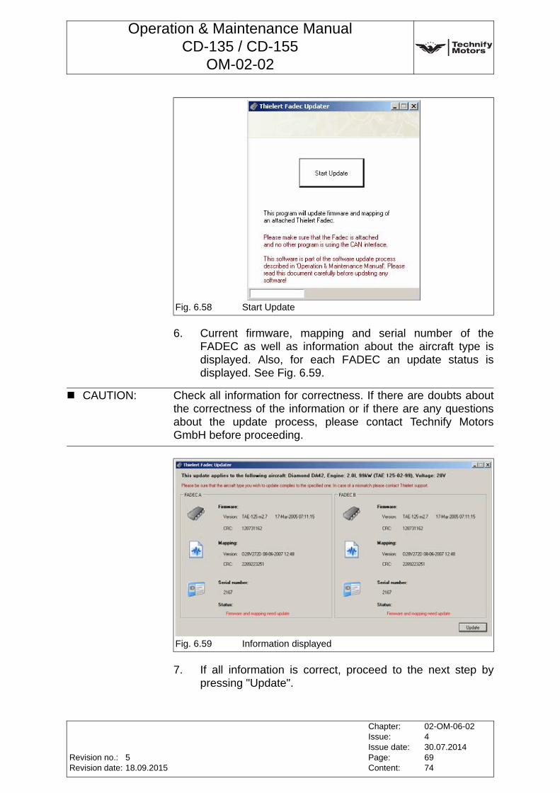
Operation & Maintenance ManualCD-135 / CD-155
OM-02-02
6. Current firmware, mapping and serial number of the FADEC as well as information about the aircraft type is displayed. Also, for each FADEC an update status is displayed. See Fig. 6.59.
7. If all information is correct, proceed to the next step by pressing "Update".
Fig. 6.58 Start Update
CAUTION: Check all information for correctness. If there are doubts about the correctness of the information or if there are any questions about the update process, please contact Technify Motors GmbH before proceeding.
Fig. 6.59 Information displayed
Revision no.:Revision date:
Chapter:Issue:Issue date:Page:Content:
02-OM-06-02430.07.20146974
518.09.2015
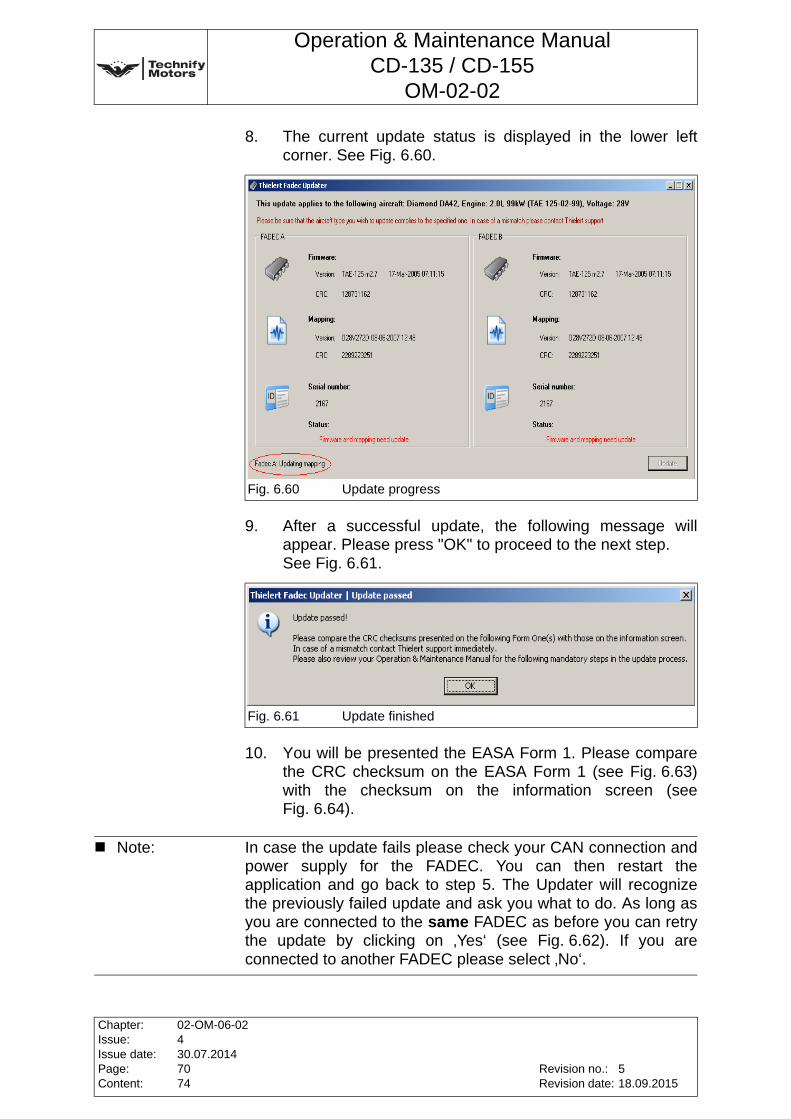
Operation & Maintenance ManualCD-135 / CD-155
OM-02-02
8. The current update status is displayed in the lower left corner. See Fig. 6.60.
9. After a successful update, the following message will appear. Please press "OK" to proceed to the next step.See Fig. 6.61.
10. You will be presented the EASA Form 1. Please compare the CRC checksum on the EASA Form 1 (see Fig. 6.63) with the checksum on the information screen (see Fig. 6.64).
Fig. 6.60 Update progress
Fig. 6.61 Update finished
Note: In case the update fails please check your CAN connection and power supply for the FADEC. You can then restart the application and go back to step 5. The Updater will recognize the previously failed update and ask you what to do. As long as you are connected to the same FADEC as before you can retry the update by clicking on ‚Yes‘ (see Fig. 6.62). If you are connected to another FADEC please select ‚No‘.
Chapter:Issue:Issue date:Page:Content:
02-OM-06-02430.07.20147074
Revision no.:Revision date:
518.09.2015
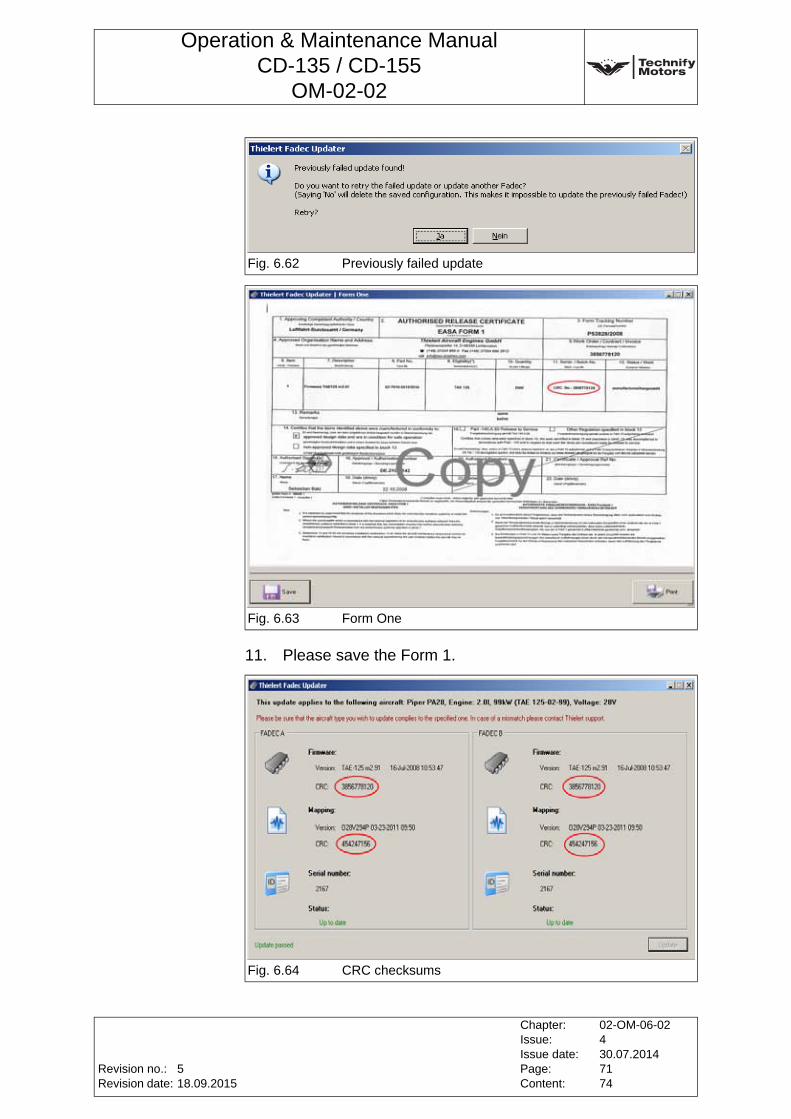
Operation & Maintenance ManualCD-135 / CD-155
OM-02-02
11. Please save the Form 1.
Fig. 6.62 Previously failed update
Fig. 6.63 Form One
Fig. 6.64 CRC checksums
Revision no.:Revision date:
Chapter:Issue:Issue date:Page:Content:
02-OM-06-02430.07.20147174
518.09.2015
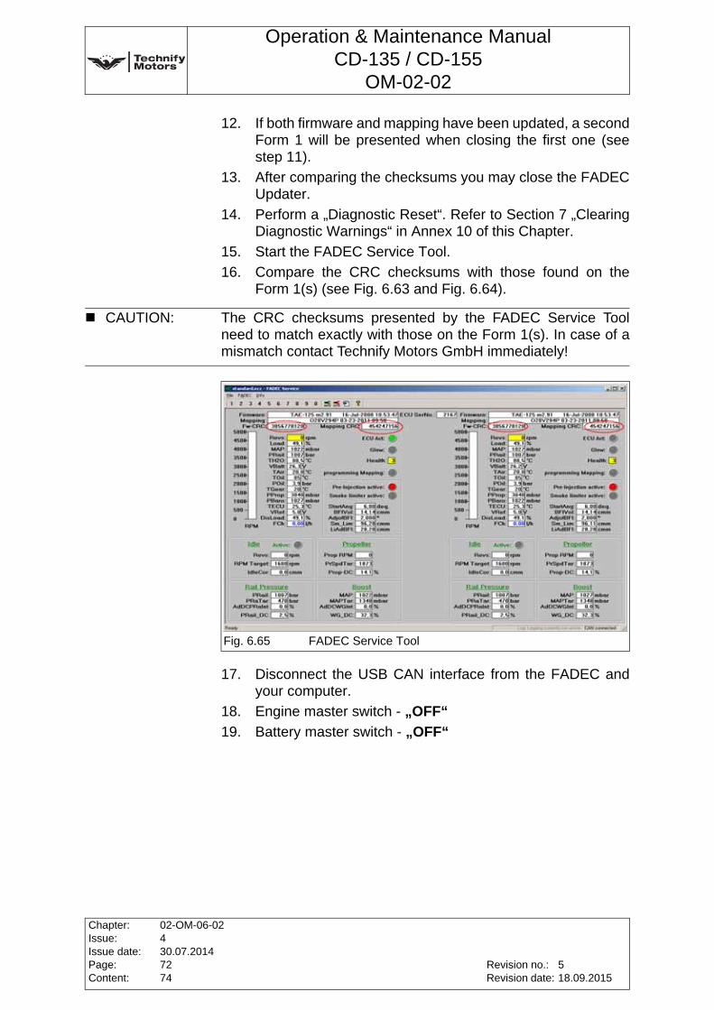
Operation & Maintenance ManualCD-135 / CD-155
OM-02-02
12. If both firmware and mapping have been updated, a second Form 1 will be presented when closing the first one (see step 11).
13. After comparing the checksums you may close the FADEC Updater.
14. Perform a „Diagnostic Reset“. Refer to Section 7 „Clearing Diagnostic Warnings“ in Annex 10 of this Chapter.
15. Start the FADEC Service Tool.
16. Compare the CRC checksums with those found on the Form 1(s) (see Fig. 6.63 and Fig. 6.64).
17. Disconnect the USB CAN interface from the FADEC and your computer.
18. Engine master switch - „OFF“
19. Battery master switch - „OFF“
CAUTION: The CRC checksums presented by the FADEC Service Tool need to match exactly with those on the Form 1(s). In case of a mismatch contact Technify Motors GmbH immediately!
Fig. 6.65 FADEC Service Tool
Chapter:Issue:Issue date:Page:Content:
02-OM-06-02430.07.20147274
Revision no.:Revision date:
518.09.2015
Operation & Maintenance ManualCD-135 / CD-155
OM-02-02
Annex 18 Inspecting the Fuel Feed PumpThe fuel feed pump must be delivered to Technify Motors GmbH for inspection.To remove and install the fuel feed pump, refer to RM-02-02.
Revision no.:Revision date:
Chapter:Issue:Issue date:Page:Content:
02-OM-06-02430.07.20147374
518.09.2015

Operation & Maintenance ManualCD-135 / CD-155
OM-02-02
This page intentionally left blank
Chapter:Issue:Issue date:Page:Content:
02-OM-06-02430.07.20147474
Revision no.:Revision date:
518.09.2015
Operation & Maintenance ManualCD-135 / CD-155
OM-02-02
7 Emergency Procedures
7.1 Power LossIn the event of power loss, move the load selector fully forward (takeoff power position) and select a fuel tank with sufficient fuel level.
7.2 FADEC OperationThe FADEC system consists of two identical and independent FADEC-halves, which continually monitor each others status. In normal operation, the manual Force B switch should be switched to the "A" position. This means that FADEC A (Engine Control Unit A) is actively controlling the engine, and FADEC B is in stand-by mode. If the FADEC system detects a problem with channel A, the FADEC A light begins to flash and the system automatically switches over to FADEC B. If the FADEC system detects a problem with channel B, the FADEC B light begins to flash, and the system automatically switches to whichever channel is the healthiest. If the Force B switch is in the "B" position, only FADEC B will be allowed to actively control the engine. In this position, the FADEC system cannot switch automatically between channel A and B. This position is necessary only if the FADEC system does not switch automatically to the healthiest channel in the event of abnormal engine behavior.
CAUTION: If the FADEC has been operated by the battery only, a temporary decrease of the rotational speed is possible by switching on the Alternator. In any case leave the Alternator switched on.
Note: The following steps must be taken in the event of power loss or engine failure!
WARNING: It is strongly recommended to always operate with the Force B switch in the "A" position, as this will allow the FADEC system to choose automatically the healthiest channel.
Revision no.:Revision date:
Chapter:Issue:Issue date:Page:Content:
02-OM-07-02430.07.201416
--
Operation & Maintenance ManualCD-135 / CD-155
OM-02-02
7.3 Engine System Malfunction
7.3.1 One FADEC light flashing
1. Press FADEC test button at least 2 seconds(refer to Chapter 4, Section 4.4.3, Page 7 of this Manual)
2. FADEC lights extinguished (temporary failure):
a) Continue flight normally
b) Inform service center after landing. The lights will illuminate after the ignition has been switched off and on.
3. FADEC lights steady illuminated (steady failure or high category failure):
a) Observe the other FADEC lamp
b) Fly to the next airfield or landing strip
c) Select an airspeed according to the appropriate POH
d) Inform service center after landing
Note: The FADEC consists of two components that are independent of each other: FADEC A and FADEC B. In case of malfunctions in the active FADEC, it automatically switches to the other.
Chapter:Issue:Issue date:Page:Content:
02-OM-07-02430.07.201426
Revision no.:Revision date:
--
Operation & Maintenance ManualCD-135 / CD-155
OM-02-02
7.3.2 Both FADEC lights flashing
1. Press FADEC-Testbutton at least 2 seconds(refer to Chapter 4, Section 4.4.3, Page 7 of this Manual)
2. FADEC lights extinguished (temporary failure):
a) Continue flight normally
b) Inform service center after landing. The lights will illuminate after the ignition has been switched off and on.
3. FADEC lights steady illuminated (steady failure or high category failure):
a) Check the available engine power
b) Expect engine failure
c) Flight can be continued, however the pilot should
• select an airspeed according to the appropriate POH
• fly to the next airfield or landing strip
• be prepared for an emergency landing
d) Inform service center after landing
7.3.3 Abnormal engine behavior
If abnormal engine behavior should occur during flight and the FADEC does not automatically switch over to FADEC B, it is possible to switch over to FADEC B manually using the "Force B" switch. However, this switch position prevents the auto-monitoring between the two FADEC halves.
Before attempting to restart the engine when on the ground, check the plug and socket connections according to Chapter 6, Annex 7, Page 18 of this Manual and carry out the “Pre-Flight Check“ as described in Chapter 6, Section 6.1, Page 2 of this Manual.
Note: The Load Display may not correspond to the current value.
WARNING: It is strongly recommended to always operate with the Force B switch in the automatic position, as this will allow the FADEC system to choose automatically the healthiest FADEC.
Revision no.:Revision date:
Chapter:Issue:Issue date:Page:Content:
02-OM-07-02430.07.201436
--
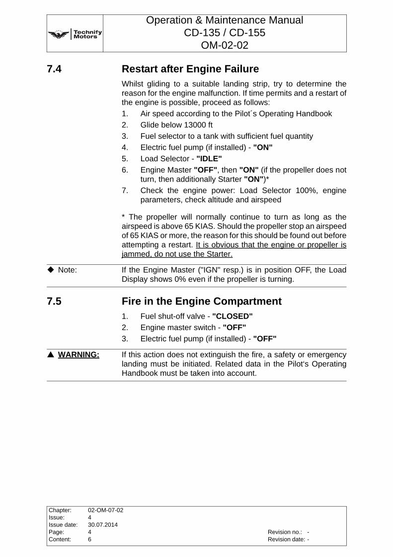
Operation & Maintenance ManualCD-135 / CD-155
OM-02-02
7.4 Restart after Engine FailureWhilst gliding to a suitable landing strip, try to determine the reason for the engine malfunction. If time permits and a restart of the engine is possible, proceed as follows:
1. Air speed according to the Pilot´s Operating Handbook
2. Glide below 13000 ft
3. Fuel selector to a tank with sufficient fuel quantity
4. Electric fuel pump (if installed) - "ON"
5. Load Selector - "IDLE"
6. Engine Master "OFF", then "ON" (if the propeller does not turn, then additionally Starter "ON")*
7. Check the engine power: Load Selector 100%, engine parameters, check altitude and airspeed
* The propeller will normally continue to turn as long as the airspeed is above 65 KIAS. Should the propeller stop an airspeed of 65 KIAS or more, the reason for this should be found out before attempting a restart. It is obvious that the engine or propeller is jammed, do not use the Starter.
7.5 Fire in the Engine Compartment1. Fuel shut-off valve - "CLOSED"
2. Engine master switch - "OFF"
3. Electric fuel pump (if installed) - "OFF"
Note: If the Engine Master ("IGN" resp.) is in position OFF, the Load Display shows 0% even if the propeller is turning.
WARNING: If this action does not extinguish the fire, a safety or emergency landing must be initiated. Related data in the Pilot‘s Operating Handbook must be taken into account.
Chapter:Issue:Issue date:Page:Content:
02-OM-07-02430.07.201446
Revision no.:Revision date:
--
Operation & Maintenance ManualCD-135 / CD-155
OM-02-02
7.6 Air in the Fuel System (During Flight)1. Move the fuel tank selector to a tank with sufficient fuel
2. Electric fuel pump (if installed) - "ON"
3. Engage the starter
7.7 Oil Pressure too Low (During Flight)1. Reduce power as quickly as possible
2. Monitor the oil pressure:
a) If the oil pressure rises into the green, continue flight with a power setting which keeps the oil pressure in the green, if possible.
b) If the oil pressure remains too low, expect engine failure and prepare for an emergency landing.
WARNING: If there is air in the fuel system, the engine stalls within a few seconds. It takes about 15 seconds before the engine restarts.
WARNING: The high-pressure pump has to be inspected before the next flight.
Note: If the engine fails due to low oil pressure, the propeller will also stop turning. The glide ratio of an aircraft with a stopped propeller is higher than with windmilling, so that the range for an emergency landing increases. Related data in the Pilot´s Operating Handbook must be taken into account.
Revision no.:Revision date:
Chapter:Issue:Issue date:Page:Content:
02-OM-07-02430.07.201456
--
Operation & Maintenance ManualCD-135 / CD-155
OM-02-02
This page intentionally left blank
Chapter:Issue:Issue date:Page:Content:
02-OM-07-02430.07.201466
Revision no.:Revision date:
--
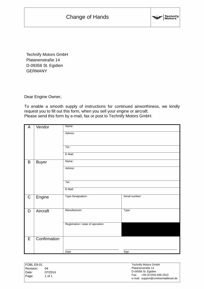
Change of Hands
FOBL E8-01Revision:Date:Page:
0407/20141 of 1
Technify Motors GmbHPlatanenstraße 14D-09356 St. EgidienFax: +49 (37204) 696-2910e-mail: [email protected]
FOBL E8-01 Change of Hands
Dear Engine Owner,
To enable a smooth supply of instructions for continued airworthiness, we kindly request you to fill out this form, when you sell your engine or aircraft.Please send this form by e-mail, fax or post to Technify Motors GmbH.
Technify Motors GmbHPlatanenstraße 14D-09356 St. EgidienGERMANY
A Vendor Name:
Adress:
Tel.:
E-Mail:
B Buyer Name:
Adress:
Tel.:
E-Mail:
C Engine Type Designation: Serial number:
D Aircraft Manufacturer: Type:
Registration / state of operation:
E Confirmation
___________________________________Date
___________________________________Sign
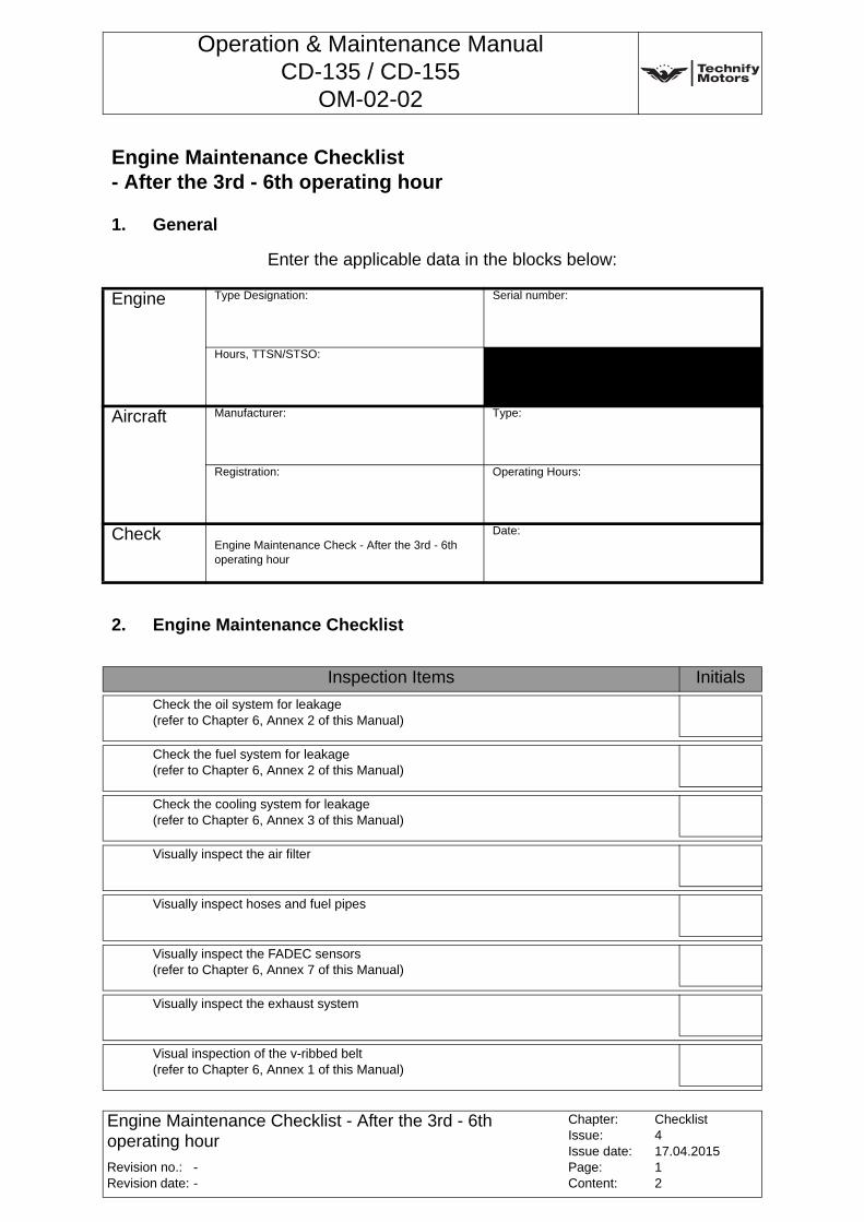
Operation & Maintenance ManualCD-135 / CD-155
OM-02-02
Enter the applicable data in the blocks below:
Engine Maintenance Checklist - After the 3rd - 6th operating hour
1. General
Engine Type Designation: Serial number:
Hours, TTSN/STSO:
Aircraft Manufacturer: Type:
Registration: Operating Hours:
CheckEngine Maintenance Check - After the 3rd - 6th operating hour
Date:
2. Engine Maintenance Checklist
Inspection Items Initials
Check the oil system for leakage (refer to Chapter 6, Annex 2 of this Manual)
Check the fuel system for leakage (refer to Chapter 6, Annex 2 of this Manual)
Check the cooling system for leakage (refer to Chapter 6, Annex 3 of this Manual)
Visually inspect the air filter
Visually inspect hoses and fuel pipes
Visually inspect the FADEC sensors (refer to Chapter 6, Annex 7 of this Manual)
Visually inspect the exhaust system
Visual inspection of the v-ribbed belt(refer to Chapter 6, Annex 1 of this Manual)
Revision no.:Revision date:
Chapter:Issue:Issue date:Page:Content:
Checklist417.04.201512
--
Engine Maintenance Checklist - After the 3rd - 6th operating hour
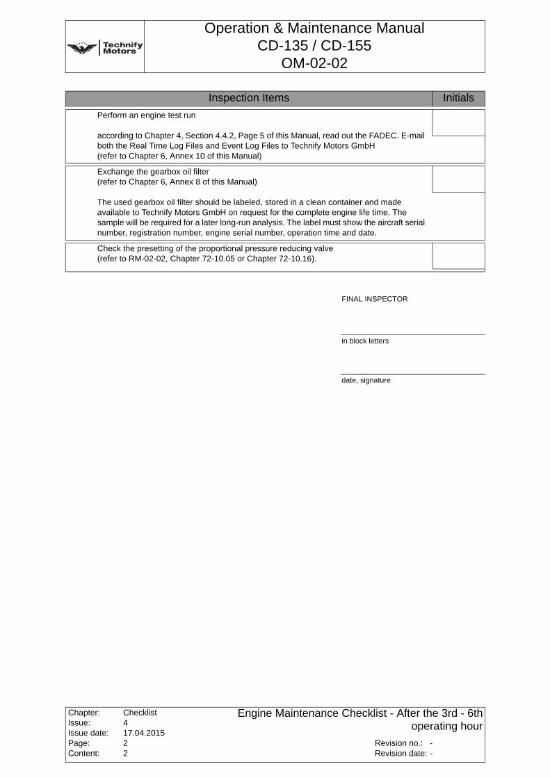
Operation & Maintenance ManualCD-135 / CD-155
OM-02-02
Perform an engine test run
according to Chapter 4, Section 4.4.2, Page 5 of this Manual, read out the FADEC. E-mail both the Real Time Log Files and Event Log Files to Technify Motors GmbH (refer to Chapter 6, Annex 10 of this Manual)
Exchange the gearbox oil filter (refer to Chapter 6, Annex 8 of this Manual)
The used gearbox oil filter should be labeled, stored in a clean container and made available to Technify Motors GmbH on request for the complete engine life time. The sample will be required for a later long-run analysis. The label must show the aircraft serial number, registration number, engine serial number, operation time and date.
Check the presetting of the proportional pressure reducing valve (refer to RM-02-02, Chapter 72-10.05 or Chapter 72-10.16).
Inspection Items Initials
FINAL INSPECTOR
in block letters
date, signature
Chapter:Issue:Issue date:Page:Content:
Checklist417.04.201522
Revision no.:Revision date:
--
Engine Maintenance Checklist - After the 3rd - 6th operating hour
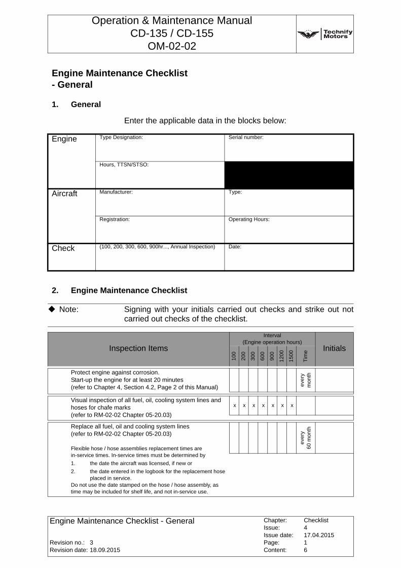
Operation & Maintenance ManualCD-135 / CD-155
OM-02-02
Enter the applicable data in the blocks below:
Engine Maintenance Checklist - General
1. General
Engine Type Designation: Serial number:
Hours, TTSN/STSO:
Aircraft Manufacturer: Type:
Registration: Operating Hours:
Check (100, 200, 300, 600, 900hr..., Annual Inspection) Date:
2. Engine Maintenance Checklist
Note: Signing with your initials carried out checks and strike out not carried out checks of the checklist.
Inspection Items
Interval(Engine operation hours)
Initials
100
200
300
600
900
120
0
150
0
Tim
e
Protect engine against corrosion. Start-up the engine for at least 20 minutes (refer to Chapter 4, Section 4.2, Page 2 of this Manual) ev
ery
mon
th
Visual inspection of all fuel, oil, cooling system lines and hoses for chafe marks (refer to RM-02-02 Chapter 05-20.03)
x x x x x x x
Replace all fuel, oil and cooling system lines(refer to RM-02-02 Chapter 05-20.03)
Flexible hose / hose assemblies replacement times are in-service times. In-service times must be determined by
1. the date the aircraft was licensed, if new or
2. the date entered in the logbook for the replacement hose placed in service.
Do not use the date stamped on the hose / hose assembly, as time may be included for shelf life, and not in-service use.
ever
y 60
mon
th
Revision no.:Revision date:
Chapter:Issue:Issue date:Page:Content:
Checklist417.04.201516
318.09.2015
Engine Maintenance Checklist - General
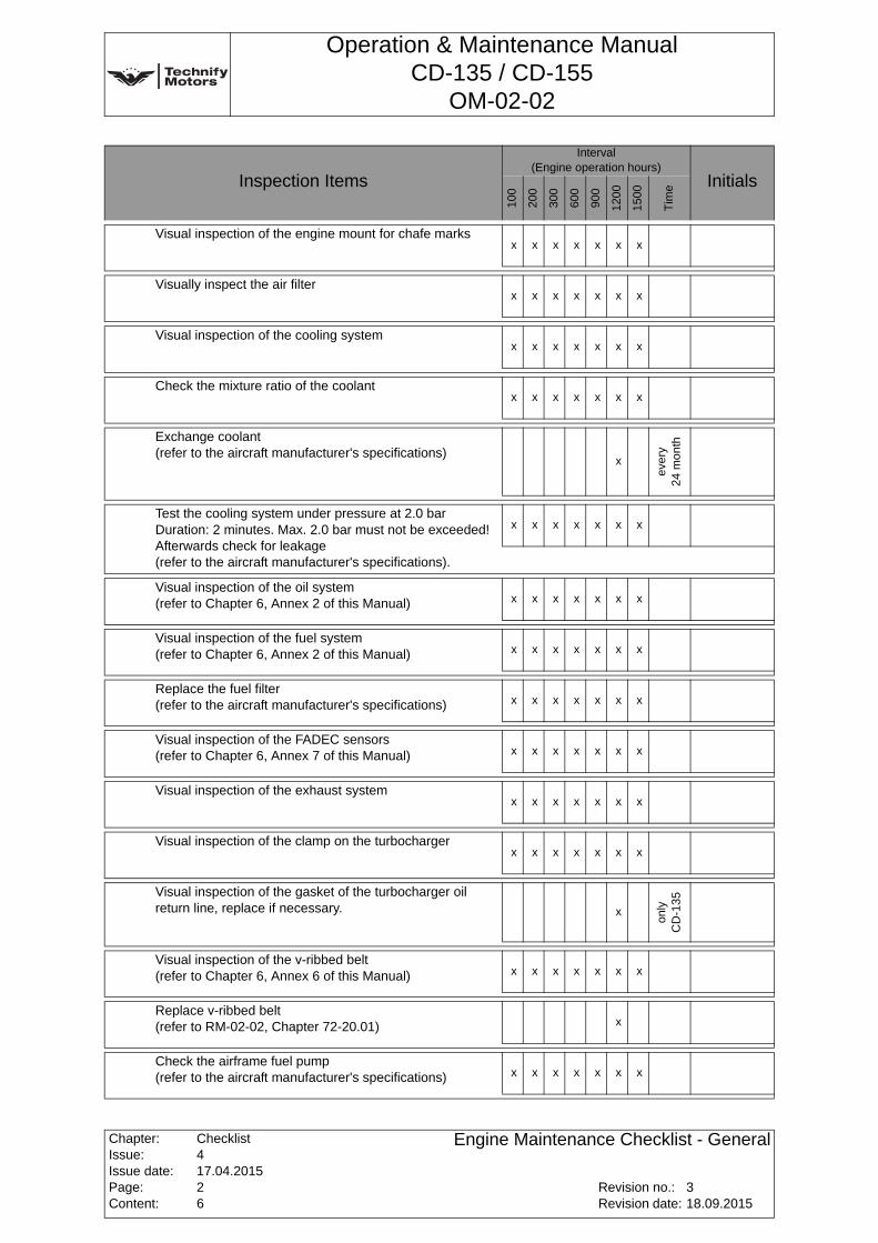
Operation & Maintenance ManualCD-135 / CD-155
OM-02-02
Visual inspection of the engine mount for chafe marksx x x x x x x
Visually inspect the air filterx x x x x x x
Visual inspection of the cooling systemx x x x x x x
Check the mixture ratio of the coolantx x x x x x x
Exchange coolant(refer to the aircraft manufacturer's specifications)
x
ever
y 24
mo
nth
Test the cooling system under pressure at 2.0 bar Duration: 2 minutes. Max. 2.0 bar must not be exceeded! Afterwards check for leakage (refer to the aircraft manufacturer's specifications).
x x x x x x x
Visual inspection of the oil system(refer to Chapter 6, Annex 2 of this Manual) x x x x x x x
Visual inspection of the fuel system(refer to Chapter 6, Annex 2 of this Manual) x x x x x x x
Replace the fuel filter (refer to the aircraft manufacturer's specifications) x x x x x x x
Visual inspection of the FADEC sensors (refer to Chapter 6, Annex 7 of this Manual) x x x x x x x
Visual inspection of the exhaust systemx x x x x x x
Visual inspection of the clamp on the turbochargerx x x x x x x
Visual inspection of the gasket of the turbocharger oil return line, replace if necessary. x
only
C
D-1
35
Visual inspection of the v-ribbed belt (refer to Chapter 6, Annex 6 of this Manual) x x x x x x x
Replace v-ribbed belt (refer to RM-02-02, Chapter 72-20.01) x
Check the airframe fuel pump (refer to the aircraft manufacturer's specifications) x x x x x x x
Inspection Items
Interval(Engine operation hours)
Initials
100
200
300
600
900
1200
1500
Tim
e
Chapter:Issue:Issue date:Page:Content:
Checklist417.04.201526
Revision no.:Revision date:
318.09.2015
Engine Maintenance Checklist - General
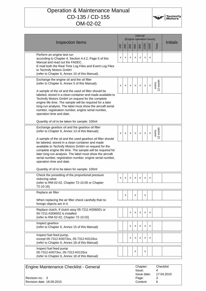
Operation & Maintenance ManualCD-135 / CD-155
OM-02-02
Perform an engine test run according to Chapter 4, Section 4.4.2, Page 5 of this Manual and read out the FADEC.E-mail both the Real Time Log Files and Event Log Files to Technify Motors GmbH (refer to Chapter 6, Annex 10 of this Manual).
x x x x x x x
Exchange the engine oil and the oil filter (refer to Chapter 6, Annex 5 of this Manual);
A sample of the oil and the used oil filter should be labeled, stored in a clean container and made available to Technify Motors GmbH on request for the complete engine life time. The sample will be required for a later long-run analysis. The label must show the aircraft serial number, registration number, engine serial number, operation time and date.Quantity of oil to be taken for sample: 100ml
x x x x x x x
ever
y 12
mon
th
Exchange gearbox oil and the gearbox oil filter (refer to Chapter 6, Annex 13 of this Manual);
A sample of the oil and the used gearbox oil filter should be labeled, stored in a clean container and made available to Technify Motors GmbH on request for the complete engine life time. The sample will be required for later long-run analysis. The label must show the aircraft serial number, registration number, engine serial number, operation time and date.
Quantity of oil to be taken for sample: 100ml
x x x x x x x
ever
y 12
mon
th
Check the presetting of the proportional pressure reducing valve (refer to RM-02-02, Chapter 72-10.05 or Chapter 72-10.16)
x x x x x x x
Replace air filter
When replacing the air filter check carefully that no foreign objects are in it.
x x x
Replace clutch, if clutch assy 05-7211-K006001 or 05-7211-K006002 is installed (refer to RM-02-02, Chapter 72-10.02)
x x x x x
Inspect gearbox (refer to Chapter 6, Annex 15 of this Manual) x x x x x
Inspect fuel feed pump, except 05-7312-K0073xx, 05-7312-K0133xx(refer to Chapter 6, Annex 18 of this Manual)
x x x x x
Inspect fuel feed pump 05-7312-K0073xx, 05-7312-K0133xx(refer to Chapter 6, Annex 18 of this Manual)
x x
Inspection Items
Interval(Engine operation hours)
Initials
100
200
300
600
900
1200
1500
Tim
e
Revision no.:Revision date:
Chapter:Issue:Issue date:Page:Content:
Checklist417.04.201536
318.09.2015
Engine Maintenance Checklist - General
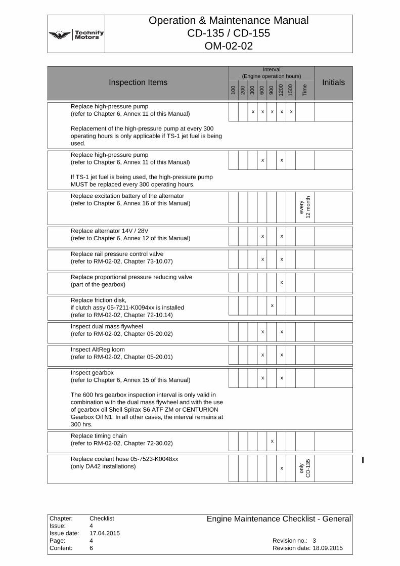
Operation & Maintenance ManualCD-135 / CD-155
OM-02-02
Replace high-pressure pump (refer to Chapter 6, Annex 11 of this Manual)
Replacement of the high-pressure pump at every 300 operating hours is only applicable if TS-1 jet fuel is being used.
x x x x x
Replace high-pressure pump (refer to Chapter 6, Annex 11 of this Manual)
If TS-1 jet fuel is being used, the high-pressure pump MUST be replaced every 300 operating hours.
x x
Replace excitation battery of the alternator (refer to Chapter 6, Annex 16 of this Manual)
ever
y 12
mon
th
Replace alternator 14V / 28V (refer to Chapter 6, Annex 12 of this Manual) x x
Replace rail pressure control valve(refer to RM-02-02, Chapter 73-10.07) x x
Replace proportional pressure reducing valve (part of the gearbox) x
Replace friction disk, if clutch assy 05-7211-K0094xx is installed (refer to RM-02-02, Chapter 72-10.14)
x
Inspect dual mass flywheel (refer to RM-02-02, Chapter 05-20.02) x x
Inspect AltReg loom (refer to RM-02-02, Chapter 05-20.01) x x
Inspect gearbox (refer to Chapter 6, Annex 15 of this Manual)
The 600 hrs gearbox inspection interval is only valid in combination with the dual mass flywheel and with the use of gearbox oil Shell Spirax S6 ATF ZM or CENTURION Gearbox Oil N1. In all other cases, the interval remains at 300 hrs.
x x
Replace timing chain (refer to RM-02-02, Chapter 72-30.02) x
Replace coolant hose 05-7523-K0048xx (only DA42 installations) x
only
C
D-1
35
Inspection Items
Interval(Engine operation hours)
Initials
100
200
300
600
900
1200
1500
Tim
e
Chapter:Issue:Issue date:Page:Content:
Checklist417.04.201546
Revision no.:Revision date:
318.09.2015
Engine Maintenance Checklist - General
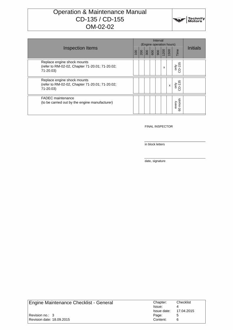
Operation & Maintenance ManualCD-135 / CD-155
OM-02-02
Replace engine shock mounts (refer to RM-02-02, Chapter 71-20.01; 71-20.02; 71-20.03)
x
only
C
D-1
55
Replace engine shock mounts (refer to RM-02-02, Chapter 71-20.01; 71-20.02; 71-20.03)
x
only
C
D-1
35
FADEC maintenance (to be carried out by the engine manufacturer)
ever
y 60
mon
th
Inspection Items
Interval(Engine operation hours)
Initials
100
200
300
600
900
1200
1500
Tim
e
FINAL INSPECTOR
in block letters
date, signature
Revision no.:Revision date:
Chapter:Issue:Issue date:Page:Content:
Checklist417.04.201556
318.09.2015
Engine Maintenance Checklist - General
Operation & Maintenance ManualCD-135 / CD-155
OM-02-02
3. this page is intentionally left blank
Chapter:Issue:Issue date:Page:Content:
Checklist417.04.201566
Revision no.:Revision date:
318.09.2015
Engine Maintenance Checklist - General