operation maintenance manual - simplicity marine pages/crusader... · cleaning sea-water section of...
TRANSCRIPT

OWNER’S OPERATION
and
MAINTENANCE MANUAL
A Divison of Pleasurecraft Engine Group

Welcome to the growing family of Crusader Engine owners. We are delighted you have chosen Crusader power for you boat and wish you many years of enjoyment.
READ THIS MANUAL THOROUGHLY
Before starting your engine(s), READ THIS MANUAL CAREFULLY AND COMPLETELY. If you do not understand any portion of the manual, contact your Dealer for clarifi cation or assistance. Ask your Dealer for a demostration of actual starting and operating procedures.
The descriptions and specifi cations contained in this manual were in effect at the time of printing. Crusader Engines’ policy of continued improvement reserves the right to change specifi cations or design without notice and without obligation.
This manual will cover the following Crusader engines:
Year Model 2002 5.0L MPI
2002 5.7L MPI
2002 8.1L MPI
2002 8.1L MPI (HO)
Part Number - L510001-02 Printed 5/02

1L510001-02
INTRODUCTION ..................................................................................................................... 3-4Registration Information ............................................................................................................... 3Safety Information ...................................................................................................................... 4Replacement Parts ........................................................................................................................... 4Safety Warnings ......................................................................................................................... 4BOATING RESPONSIBILITY .................................................................................................... 5-8Carbon Monoxide Hazard ............................................................................................................ 5Safe Boating Suggestions ............................................................................................................ 7Water Wisdom ........................................................................................................................... 7Operation and Maintenance .......................................................................................................... 7Rules of the Road ....................................................................................................................... 8ENGINE IDENTIFICATION ...................................................................................................... 9-10Engine Identifi cation .................................................................................................................... 9Owner Identifi cation and Registration Information ............................................................................. 92002 Model Identifi cation / Advisory ............................................................................................. 10ELECTRONIC FUEL INJECTION INFORMATION ..................................................................... 11-13Electronic Fuel Injection System .................................................................................................. 11Power Reduction Mode .............................................................................................................. 12High Engine Coolant Temperature ................................................................................................ 12Low Engine Oil Pressure ............................................................................................................ 13High Transmission Fluid Temperature ............................................................................................ 13OPERATING INSTRUCTIONS ................................................................................................ 14-18Engine Alarm System ................................................................................................................ 14Instrumentation ........................................................................................................................ 14Remote Controls ...................................................................................................................... 15Starting Engine (Fuel Injected Engines) ........................................................................................ 16Shifting Transmission ................................................................................................................. 17Stopping Engine ....................................................................................................................... 18Freezing Temperature Operation .................................................................................................. 18Operation in High Debris Areas ................................................................................................... 18CONDITIONS AFFECTING OPERATION ................................................................................. 19-20Trim and Weight Distribution ........................................................................................................ 19Boat Bottom ............................................................................................................................. 19Propeller Selection .................................................................................................................... 20ENGINE BREAK-IN PERIOD ..................................................................................................... 2125-HOUR ENGINE INSPECTION ................................................................................................ 22FUEL REQUIREMENTS ............................................................................................................ 23Gasoline Requirements .............................................................................................................. 23Gasoline Containing Alcohol ....................................................................................................... 23
TABLE OF CONTENTS

2 L510001-02
OIL REQUIREMENTS ............................................................................................................... 24Engine Oil Recommendations ..................................................................................................... 24Transmission and “V”-Drive Oil Requirements ................................................................................. 24ENGINE MAINTENANCE ...................................................................................................... 25-51Engine Maintenance .................................................................................................................. 25Checking Fluid Levels ........................................................................................................... 25-26Lubrication .............................................................................................................................. 27Electrical System Circuit Breaker(s) .............................................................................................. 28Electrical System Fuses ............................................................................................................. 28Ignition Fuse ............................................................................................................................ 28Electrical System Wiring and Connectors ...................................................................................... 28Battery .................................................................................................................................... 29Fresh Water Cooling System Sacrifi cial Zinc Anode ......................................................................... 30Checking Coolant Level ............................................................................................................. 31Flushing Cooling System - Sea-Water Section ................................................................................ 32Testing Coolant For Alkalinity ...................................................................................................... 33Draining Fresh-Water Cooling System .......................................................................................... 33Filling Fresh-Water Cooling System .............................................................................................. 34Cleaning Sea-Water Section of Heat Exchanger (Fresh-Water Cooled Applications Only) ....................... 35Fuel System Description ............................................................................................................ 36Fuel Control Cell (FCC) Fuel System ............................................................................................ 36Servicing the FCC ..................................................................................................................... 37Draining the FCC Bowl, ENGINE OFF .......................................................................................... 38Filter Element Replacement, ENGINE OFF .................................................................................... 38Primary Fuel Filter .................................................................................................................... 39Priming Fuel System ................................................................................................................. 40Flame Arrestor ......................................................................................................................... 40Accessory Drive Belt ............................................................................................................. 41-42Changing Oils .......................................................................................................................... 43Engine Alignment ................................................................................................................. 44-46Engine Maintenance Log ............................................................................................................ 47Maintenance Schedule .............................................................................................................. 48Visual Inspection ...................................................................................................................... 50Engine Fluid Capacities ............................................................................................................. 50Transmission Fluid Capacities ..................................................................................................... 50Filter Requirements ................................................................................................................... 51ENGINE SPECIFICATIONS ................................................................................................... 52-53OUT-OF-SEASON STORAGE ................................................................................................ 54-57Engine Storage ........................................................................................................................ 54Draining Instructions .................................................................................................................. 55Battery Storage ........................................................................................................................ 56Fitting Out After Storage ............................................................................................................. 57
TABLE OF CONTENTS

3L510001-02
REGISTRATION INFORMATION
Make certain that your Dealer or engine seller fi lls out and mails your warranty registration card (contained in “Owners Warranty and Service Guide”) to Crusader Engines within 10 days of purchase. If you do not receive your “Owner Registration Card” within 30 days from the date of sale, please contact your boat dealer or engine seller.
Mail registration information to:
Crusader EnginesP.O. Box 369
Little Mountain, SC 29075
For details on warranty coverage, see “Owner’s Service and Warranty Guide.”
INTRODUCTION - 1TROUBLESHOOTING .......................................................................................................... 58-60WATER FLOW DIAGRAMS ................................................................................................... 61-65INSTRUMENTATION WIRING DIAGRAM ..................................................................................... 66LITERATURE .......................................................................................................................... 67NOTES ............................................................................................................................... 68-69

4 L510001-02
INTRODUCTION - 1SAFETY INFORMATION
“Safety Warnings” and additional information or instructions are used to alert the installer/operator of possible safety hazards in performing certain service or maintenance procedures incorrectly or carelessly. DANGERS and WARNINGS are accompanied by the international HAZARD symbol:
These “Safety Warnings” alone cannot eliminate the hazards that they signal. Strict compliance with these warning instructions while performing service and maintenance procedures, plus “common sense” operation, are major accident prevention measures.
REPLACEMENT PARTS
Use of replacement parts (i.e. automotive, after-market, etc.) in the electrical, ignition and fuel systems, which are not U.S. Coast Guard approved, could cause a fi re or explosion hazard and should be avoided.
Always request that genuine Crusader Engines replacement parts be used in any repairs or maintenance being performed on your engine(s).
DANGER
Electrical, ignition and fuel system components are designed and manufactured to comply with U.S. Coast Guard rules and regulations to minimize the possibility of fi re or explosion hazard.
DANGER
Signals serious damage, failure or breakdown of equipment; severe injury or high probability of death to the user if proper precautions are not taken. This signal word is applied in extreme situations
SAFETY WARNINGS
WARNING
Indicates a potential hazard which could result in personal injury.
CAUTION
Indicates a hazard which could result in damage to equipment.
IMPORTANT: or IMPORTANT: Used to provide information to perform a procedure more easily.
WARRANTY NOTICE: Indicates a possible warranty exclusion.

5L510001-02
BOATING RESPONSIBILITIES - 2CARBON MONOXIDE HAZARD
Carbon monoxide is produced when anything that contains carbon, such as gasoline, natural gas, oil, propane, coal or wood is burned. Carbon monoxide is commonly found in the exhaust of internal combustion engines (boat power plants, generators, etc.). In additon, open fl ame devices like cooking ranges, heaters and charcoal grills also produce carbon monoxide.
Carbon monoxide accumulation, in and around boats is affected by vessel geometry; overall vessel design; closeness to other structures; wind direction; boat speed; and many other variables. In no way can this section cover all of the possible variables. Do not rely on this section as the exclusive listing of measures to prevent the accumulation of carbon monoxide.
Consult your boat operators manual for detailed information on the inspection and/or maintenance of the exhaust system for your particular application. If an inspection reveals possible leaks, DO NOT operate your engine(s) until it can be serviced by a qualifi ed technician.
Proper and adequate air circulation, around and throughout the boat, is absoulutely necessary to aid in the prevention of carbon monoxide build-up. If you have any questions or concerns regarding the operation of your boat and carbon monoxide hazards, DO NOT operate your engines until you have contacted your boat manufacturer.
DANGER
Carbon Monoxide (CO) is a colorless, odorless and tasteless gas. You cannot see it, smell it or taste it. Prolonged exposure to carbon monoxide can lead to unconsciousness, brain damage or death!
To fi nd out more about making boating safer, including how you can prevent carbon monoxide poisoning on recreational boats, contact:
National Marine Manufacturers Association200 East Randolph Drive
Suite 5100Chicago, IL 60601-6528
www.nmma.org312-946-6200
United States Coast GuardOffi ce of Boating Safety
CG Headquarters G-OPB-32100 Second Street SWWashington, DC 20593www.uscgboating.org
202-267-0984
American Boat & Yacht Council, Inc.3069 Solomon’s Island RoadEdgewater, MD 21037-1416
www.abyc.com410-956-1050

6 L510001-02
BOATING RESPONSIBILITIES - 2
This Page Was
Intentionally
Left Blank

7L510001-02
BOATING RESPONSIBILITIES - 2SAFE BOATING SUGGESTIONS
The nation’s waterways are becoming increasingly crowded and, in order to enjoy them safely, the operator should acquaint himself/herself with safe boating practices. Boating safely and seamanship courses are offered by the following national and state organizations:
• Power Squadrons • Coast Guard Auxiliary • Red Cross • State, provincial or local agencies in charge of water safety enforcement
Crusader Engines highly recommends that all power boat operators attend one of these courses. To help locate a course being offered near you, contact Boat U.S. Foundation’s toll-free national boating safety hotline, 1-800-336-BOAT, and in Virginia, 1-800-245-BOAT.
WATER WISDOM
The following are suggestions for safe operation of your boat to ensure the safety of yourself and your passengers:
• Know your boat’s loading and operating limitations. DO NOT OVERLOAD! • Make periodic checks of safety equipment onboard. • Do not consume alcoholic beverages or take illegal drugs when operating a boat. Some state laws apply to boats as well as motor vehicles. • File a “fl oat plan.” Let someone know your destination and your expected time of return. • Monitor the weather. Know the signs of weather change and avoid severe weather and rough seas whenever possible. • Follow the “Rules of the Road” when boating. Always be on the alert and watch out for “the other guy.” • Plan and chart your course. Be aware of, and avoid, hazardous areas. • Be sure your boat is equipped with the required safety equipment. Check with the Coast Guard and local government agencies as to the regulations and restrictions in your area. Contact your local Coast Guard Auxiliary and take advantage of their seasonal boat inspections.
The following is a list of suggested safety equipment and spare parts which may be useful in case of an emergency:
• Approved personal fl otation devices (life jackets); one for each person on board. • Approved throwable personal fl otation device for man-overboard protection. • Approved fi re extinguishers • Signal devices: fl ares, spotlight, signal fl ag and horn or whistle • Crusader Engines’ “Onboard Kit,” plus spare fuses, bulbs, batteries, etc. Tools necessary for minor repairs • Spare propeller • Anchor and anchor line • First aid kit and fi rst aid book • Ship-to-shore radio, compass and chart of the area in which you are traveling • Manual bilge pump and spare drain plugs • Waterproof storage containers
OPERATION AND MAINTENANCE
It is the owner’s/operator’s responsibility to perform all safety checks before operating his/her boat. All lubrication and maintenance schedules must be adhered to assure optimum performance and dependability from your Crusader engine. When service and maintenance are required, return to your authorized Crusader Engine Dealer.

8 L510001-02
RULES OF THE ROADChannel Buoy Guide
The color of the paint is the only characteristic which has the same meaning on all buoys. Red buoys always indicate the starboard side of the channel from seaward. (Red Right Returning) 1. Nun Buoy: This buoy indicates the starboard side of the channel when returning from sea. It is conical shape, the color red and indicates even numbers. A nun buoy with red and green horizontal bands (top band red), and not numbered, indicates an obstruction. The principal channel is to the left of the buoy when returning from sea.
2. Can Buoy: This buoy indicates the port side of the channel when returning from sea. It is cylindrical shape, the color green and indicates odd numbers. A can buoy with green and red horizontal bands (top band green), and not numbered, indicates an obstruction. The principal channel is to the right of the buoy when returning from sea.
3. Lighted Buoy (RED): This buoy has a fl ashing red light. It indicates the starboard side of the channel when returning from sea.
4. Lighted Buoy (GREEN): This buoy has a quick fl ashing green light. It indicates the port side of the channel when returning from sea. The quick fl ashing light indicates special caution required.
BOATING RESPONSIBILITIES - 2Boat Capacity • Load only to manufacturer’s specifi cations • Distribute load evenly; keep it low • Passengers should only ride on the parts of the boat that are designed for that purpose • If water is rough, carry fewer passengers
Observe the Rules of the Road
PORT (Left) - Leaving the harbor with green buoys to your right.STARBOARD (Right) - Entering the harbor with red buoys to your right.
Know Your Horn Signals
1 Short Blast = Passing you on my port side2 Short Blasts = Passing you on my starboard side3 Short Blasts = I am going astern5 Short Blasts = DangerAlways refer to the latest U.S. Coast Guard Navigation Rules CG-169
Keep An Alert Lookout For:Bad weather, Swimmers, Other boats, Water skiers, Fisherman, Divers and/or any other obstructions
Keep Your Wake Under Control, particularly upon entering or leaving harbor areas. You are responsible for wake damage to other vessels and/or property.
Do Not Fool With Fuel1/2 pint of gasoline = 15 sticks of dynamite
1. During fueling, moor boat properly; remove all passengers. 2. Keep all doors, hatches and ports closed. 3. Shut down all electronic gear; extinguish galley fi res, pilot lights and smoking materials. 4. Do not overload tanks. 5. Keep fi lling nozzles in contact with the fi ll pipe to prevent sparks. 6. Secure the fi ll cap tightly; wipe away any spillage. 7. Ventilate all components for a minimum of fi ve minutes before starting engines. 8. Keep fuel lines and bilges clean.
2
5
Small Craft Winds up to
38 MPH
Gale Winds 38 - 54 MPH
Storm Winds over 55 MPH
Hurricane Winds over
63 MPH
Storm Warning Signals - Pennants (by day) Lights (by night)
Keep to Right in narrow channels.
Boat being overtaken has right of way.
Overtaking boat must stay clear.
Yield to boats approaching in
this area.

9L510001-02
ENGINE IDENTIFICATION - 3ENGINE IDENTIFICATION
When ordering service parts or obtaining information, always give the engine model and the serial number. This information can be found on the following decal.
Figure 3-2 Engine Identifi cation Tag Locations (8.1L)
ENGINE SPARK W.O.T.�
MODEL PLUG RPM
5.7 MPI AC - MR43LTS 4800-5000
8.1 MPI DENSO / TJ14R-P15 4200-4600
8.1 MPI (HO) DENSO / TJ14R-P15 4400-5000
Fuel Oct Reg............................................MIN 87 AVG
Eng Oil Type..............Above 50 F - SAE 15W-40 "SJ"
Below 50 F - SAE 5W-40 "SJ"
Trans Fluid Type...........................................Dexron III
Firing Order............................LH 1-8-4-3-6-5-7-2 (5.7)
LH 1-8-7-2-6-5-4-3 (8.1)
Spark Plug Gap......................................0.045 in. (5.7)
0.060 in. (8.1)
Idle RPM....................................650 (Non-adjustable)
Initial Timing........................................Non-adjustable
MAKE
MODEL SERIAL
FIRING ORDER
THIS ENGINE CONFORMS TO ALL APPLICABLE U.S.GOVERNMENT STANDARDS FOR MARINE ENGINESIN EFFECT AT DATE OF MANUFACTURE.
LITTLE MOUNTAIN, SC 29075
21
1. ENGINE SPECIFICATION DECAL
2. ENGINE IDENTIFICATION DECAL
3. TRANSMISSION
IDENTIFICATION PLATE
3
MODEL
MARINE
ZF HURTH MARINEARCO ITALY
RATIO I
RATIO II
S/N-P/N
MAKE
MODEL SERIAL
FIRING ORDER
THIS ENGINE CONFORMS TO ALL APPLICABLE U.S.GOVERNMENT STANDARDS FOR MARINE ENGINESIN EFFECT AT DATE OF MANUFACTURE.
LITTLE MOUNTAIN, SC 29075
Figure 3-1 Engine Identifi cation Decal
PORT STARBOARD Engine Model Number:
Serial Number(s):
Gear Model Number:
Serial Number(s):
Boat Make:
Boat Model:
Hull Serial Number:
Propeller Size:
Ignition Key Number:
OWNER IDENTIFICATION AND REGISTRATION INFORMATION
We suggest that you record the following information for quick reference when ordering parts or requesting service or warranty.

10 L510001-02
ENGINE IDENTIFICATION - 3
CRUSADER2002 MODEL IDENTIFICATION / ADVISORY
MODEL C X L X H F L 245 M SERIAL 621254
8th 9th 10th Spaces: DRIVE GEAR RATIO OR REDUCTION The drive gear ratio will appear in these spaces which identifi es the production gear specs. The example gear number shown is a (2.45:1). If the gear being identifi ed does not have 3 digits, a “0” will appear in 10th space. Example: ( 2.0:1 ) will appear as 200 ( 1.5:1 ) will appear as 150
*MODELS ENDING WITH “000000” IN PLACE OF DRIVE I.D. ARE BOBTAIL ENGINES.
11th Space: IGNITION / FUEL TYPE USED D - DISTRIBUTOR (Carb) E - THROTTLE BODY INJECTION M - MULTI-PORT FUEL INJECTION
*SERIAL NUMBER I.D.*1st DIGIT INDICATES DECADE ENGINE WAS MANUFACTURED ( 5 = 1990, 6 = 2000, 7 = 2010 )2nd DIGIT INDICATES YEAR ENGINE WAS MANUFACTURED.
1st Space: MANUFACTURER C - Crusader
2nd Space: FACTORY FRESHWATER / CLOSED COOLING X-Freshwater Cooled (Space Omitted If Raw Water Cooled )
3rd Space: ENGINE ROTATION L - Rotation, Left-Hand from Rear R - Rotation, Right-Hand from Rear
4th Space: ENGINE TYPE A = 5.7L (350 CID HO) (GM) G = 5.0L (305 CID) (GM) X = 8.1L (496 CID STD) (GM) Z = 8.1L (496 CID HO) (GM)
5th Space: DRIVE MANUFACTURER W - Borg-Warner H - Hurth T - Walters V – Velvet Drive (cast iron units specify 71c or 72c)
6th Space: DRIVE FUNCTION / APPLICATION R - Reverse / Reduction V - Vee Drive / Reversed Risers F - Full Reversing
7th Space: PROPELLER SHAFT ROTATION L - Left-Hand Rotation R - Right-Hand Rotation

11L510001-02
ELECTRONIC FUEL INJECTION INFORMATION - 4ELECTRONIC FUEL INJECTION SYSTEM
The Crusader engines covered in this manual are equipped with an Electronic Fuel Injection (EFI) system, which allows precise control of fuel and spark delivery. The fuel system components of the EFI system are: • The electric fuel pump • The throttle body assembly • The fuel injectors
The fuel injection system is controlled by an Electronic Control Module (ECM). The ECM is the decision center of the system. The ECM constantly monitors information from various sensors on the engine, and electronically processes the information, in order to control ignition timing and fuel delivery for optimum performance and fuel economy. The ECM incorporates an engine overspeed protection, calibrated to a specifi c RPM, to prevent engine damage from over-revving.
The sensors that the ECM monitors are: • Engine Coolant Temperature (ECT) Sensor • Throttle Position (TP) Sensor • Manifold Absolute Pressure (MAP) Sensor • Knock Sensor (KS) System • Crankshaft Positioning (CKP) Sensor • Camshaft Positioning (CMP) Sensor • Intake Air Temperature (IAT) Sensor
If, for any reason, one or more of these sensors or associated wiring malfunctions, the ECM’s built-in self-diagnostic system sets a trouble code and turns on the “Check Engine” light (if equipped) to alert the operator of a malfunction.
In most cases, when the “Check Engine” light is on, the engine(s) will lose some performance and/or effi ciency, but remain running adequately. Also, the light may go out or become intermittent, but a trouble code will be logged for future diagnosis.
In any case, the operator must obtain service by an authorized dealer to determine the exact cause of the malfunction.
Figure 4-1 Check Engine Light Illuminated
WATER
TEMP
OIL
PRESS
CHK
ENGINE
TRANS
TEMP

12 L510001-02
ELECTRONIC FUEL INJECTION INFORMATION - 4POWER REDUCTION MODE
The ECM monitors engine oil pressure, engine coolant temperature and transmission oil temperature whenever the engine is running. If any one of these inputs indicate an abnormal reading, the system will go into “Power Reduction” mode, followed by the illumination of an indicator lamp and/or sounding of the warning buzzer (if equipped). This is a feature that will help protect the engine or transmission during an over-temp or low oil pressure condition.
When in “Power Reduction” mode, the ECM will allow normal engine performance up to 2000 RPM. Above 2000 RPM, the ECM allows fuel delivery through only half of the fuel injectors. Once the RPM is brought down below 1200 RPM, normal engine operation is restored until the RPM exceeds 2000 RPM. The feature allows maneuverablility of the boat while removing the possibility of high engine speed operation until the problem is corrected.
On twin engine applications, if confi gured correctly by the installer, BOTH engines will be limited to 2000 RPM.
NOTICE: If it is not possible to safely shut off the engine(s), return the engine(s) to idle speed. Once returned to idle, the ECM will allow the engine(s) to operate normally below 2000 RPM.
High Engine Coolant Temperature
During operation, if the engine coolant temperature exceeds 210˚ F (100˚ C), the engine enters “Power Reduction” mode and illuminates the WATER TEMP portion of the warning light cluster (if equipped). A warning buzzer will also sound (if equipped).
Figure 4-2 WATER TEMP Light Illuminated
WATER
TEMP
OIL
PRESS
CHK
ENGINE
TRANS
TEMP

13L510001-02
ELECTRONIC FUEL INJECTION INFORMATION - 4Low Engine Oil Pressure
During operation, if the engine oil pressure drops below 25 psi with the engine above 2000 RPM, the engine enters “Power Reduction” mode and illuminates the OIL PRESS portion of the warning light cluster (if equipped). A warning buzzer will also sound (if equipped).
Figure 4-3 OIL PRESS Light Illuminated
High Transmission Fluid Temperature
During operation, if the transmission fl uid temperature exceeds 235˚ F (113˚ C), the engine enters “Power Reduction” mode and illuminates the TRANS TEMP portion of the warning light cluster (if equipped). A warning buzzer may also sound (if equipped).
Figure 4-4 TRANS TEMP Light Illuminated
WATER
TEMP
OIL
PRESS
CHK
ENGINE
TRANS
TEMP
WATER
TEMP
OIL
PRESS
CHK
ENGINE
TRANS
TEMP
If a problem occurs in any of the forementioned areas, return the boat to your Crusader Engine Dealer for service.

14 L510001-02
ENGINE ALARM SYSTEM (OPTIONAL)
The Crusader engine electronic system is programmed to control the engine alarm system. This system utilizes an audible alarm and/or optional indicator lamps to warn the operator of possible engine problems, and that the engine(s) have entered the “Power Reduction” mode as covered earlier in this manual.
The alarm has a “self” checking feature programmed into the system. This feature will sound the alarm for two short pulses upon initial start-up of the engine.
If the alarm sounds during operation, immediately throttle back to idle speed. Observe the indicator lamps to locate the problem circuit. If the boat can be safely navigated with one engine, on twin engine applications, or can be anchored safely, the engine should be shut off to prevent damage to the engine or transmission.
NOTICE: Some boat builders may install their own alarm system. It is recommended that the boat owner check with his or her boat dealer for an explanation of the particular alarm system upon initial delivery.
OPERATING INSTRUCTIONS - 5INSTRUMENTATION
Boat manufacturers install many different types of instrumentation on boats. Become familiar with the instrumentation on your boat and be aware of abnormal operating conditions. The following is a brief explanation of typical instrumentation found on most boats:
1. Tachometer - indicates the engine RPM (revolutions per minute)
2. Engine Synchronizer (twin engines only)
3. Water Temperature Gauge - indicates the engine coolant temperature
4. Oil Pressure Gauge - indicates the engine oil pressure
5. Voltmeter - indicates the battery voltage and charging system voltage
6. Hour Meter - indicates the engine operating time

15L510001-02
REMOTE CONTROLS
Your boat may be equipped with one of many different types of remote controls available. Ask you dealer for a description and/or demostration of the particular type installed on your boat.
OPERATING INSTRUCTIONS - 5
TACH
0
1020 30
60
50
40
TACH
0
1020 30
60
50
40
SYNC
PORT
SLOW
STBD
SLOW
BILGE BLOWER
SWITCH
IGNITION FUSES
IGNITION SWITCHES
F F
VOLT
10 16
13
VOLT
10 16
13
E
FUEL
HOURS
1/2
F
TEMP
80
40
0
OIL
200
170
100
TEMP
200
170
10080
40
0
OIL
CHECK
ENGINE
CHECK
ENGINE
8
3
1 2
6
7
4
5
Figure 5-1 Typical Instrument Panel
CAUTION
Never shift transmission into or out of gear unless throttle is at the idle position. Shifting transmission above 1000 RPM can severly damage boat, transmission and engine.
Figure 5-2 Typical Dash Layout
TACH
0
1020 30
60
50
40
TACH
0
1020 30
60
50
40
SYNC
PORT
SLOW
STBD
SLOW
F F
VOLT
10 16
13
VOLT
10 16
13
E
FUEL
HOURS
1/2
F
TEMP
80
40
0
OIL
200
170
100
TEMP
200
170
10080
40
0
OIL
CHECK
ENGINE
CHECK
ENGINE
SHIFT
CONTROLTHROTTLE
CONTROL
IGNITION
FUSES
IGNITION
SWITCH
BILGE
BLOWER
SWITCH
"CHECK
ENGINE"
LIGHTS

16 L510001-02
STARTING ENGINE (FUEL INJECTED ENGINES)
WARNING
Electrical, ignition and fuel system components on Crusader Engines are designed and manufactured to comply with U.S. Coast Guard rules and regulations to minimize risks of fi re.
OPERATING INSTRUCTIONS - 5After performing the initial safety checks, proceed as follows to start the engine:
1. Turn the battery switch ON (if equipped).
2. Open the fuel valve.
3. Open the seacock.
4. Place the remote control in Neutral position. The transmission is equipped with a neutral safety switch, which will not allow the starter motor to operate unless the transmission is in neutral.
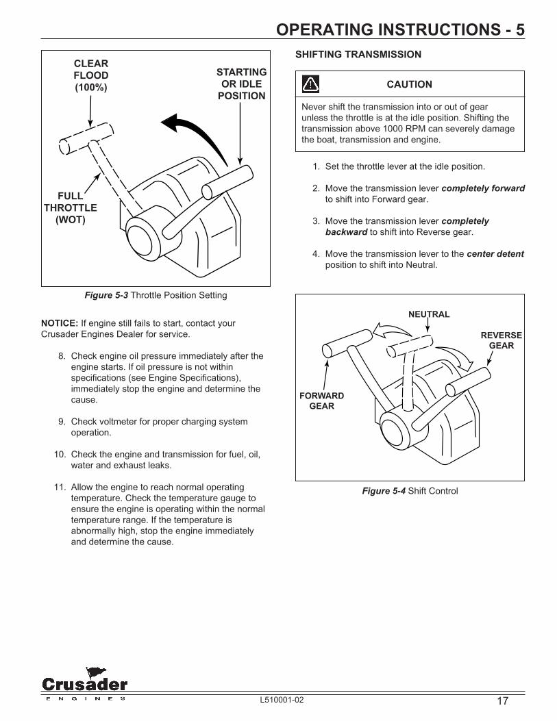
5. Do not pump or open the throttle when starting the engine (Figure 5-3). The ECM will automatically regulate the fuel and control desired idle speed.
6. Turn the ignition key to the start position. When the engine starts, release the key.
NOTICE: Engine idle speed is controlled by the ECM and is based on the operating temperature of the engine. Upon initial start-up, engine RPM will be slightly higher and will automatically decrease as the engine operating temperature increases.
7. In the event the engine becomes fl ooded, move the throttle lever to a 100% open position (Figure 5-3). At this throttle position, the ECM will command the injectors to deliver no fuel during engine cranking.
IMPORTANT: If the engine fails to start within 20-30 seconds, turn the ignition key to the OFF position and allow 2 minutes for the starter motor to cool off before attempting to restart the engine.
IMPORTANT: Do not start the engine without water being supplied to the sea water pick-up pump or sea-water pump impeller will be damaged, and subsequent overheating damage to the engine may result.
IMPORTANT: The following items should be checked before starting the engine, and each time the boat is operated:
• Fuel system for any signs of leakage
• Cooling system for leaks. If equipped with fresh- water cooling, check coolant level in recovery bottle.
• Operation of remote controls and steering
• Engine and transmission oil levels
• Fuel tank levels
• Exhaust system for leaks and tightness of the clamps
• Battery connections and water level in battery cells
• Accessory drive belt
17L510001-02
Figure 5-3 Throttle Position Setting
OPERATING INSTRUCTIONS - 5
NOTICE: If engine still fails to start, contact your Crusader Engines Dealer for service.
8. Check engine oil pressure immediately after the engine starts. If oil pressure is not within specifi cations (see Engine Specifi cations), immediately stop the engine and determine the cause.
9. Check voltmeter for proper charging system operation.
10. Check the engine and transmission for fuel, oil, water and exhaust leaks.
11. Allow the engine to reach normal operating temperature. Check the temperature gauge to ensure the engine is operating within the normal temperature range. If the temperature is abnormally high, stop the engine immediately and determine the cause.
SHIFTING TRANSMISSION
CAUTION
Never shift the transmission into or out of gear unless the throttle is at the idle position. Shifting the transmission above 1000 RPM can severely damage the boat, transmission and engine.
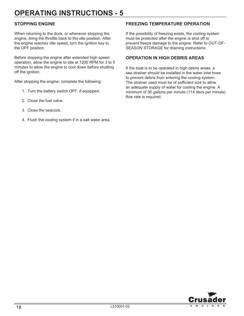
1. Set the throttle lever at the idle position.
2. Move the transmission lever completely forward to shift into Forward gear.
3. Move the transmission lever completely backward to shift into Reverse gear.
4. Move the transmission lever to the center detent position to shift into Neutral.
Figure 5-4 Shift Control
FULL
THROTTLE
(WOT)
CLEAR
FLOOD
(100%)
STARTING
OR IDLE
POSITION
NEUTRAL
FORWARD
GEAR
REVERSE
GEAR
18 L510001-02
STOPPING ENGINE
When returning to the dock, or whenever stopping the engine, bring the throttle back to the idle position. After the engine reaches idle speed, turn the ignition key to the OFF position.
Before stopping the engine after extended high speed operation, allow the engine to idle at 1200 RPM for 3 to 5 minutes to allow the engine to cool down before shutting off the ignition.
After stopping the engine, complete the following:
1. Turn the battery switch OFF, if equipped.
2. Close the fuel valve.
3. Close the seacock.
4. Flush the cooling system if in a salt water area.
OPERATING INSTRUCTIONS - 5FREEZING TEMPERATURE OPERATION
If the possibility of freezing exists, the cooling system must be protected after the engine is shut off to prevent freeze damage to the engine. Refer to OUT-OF-SEASON STORAGE for draining instructions.
OPERATION IN HIGH DEBRIS AREAS
If the boat is to be operated in high debris areas, a sea strainer should be installed in the water inlet hose to prevent debris from entering the cooling system. The strainer used must be of suffi cient size to allow an adequate supply of water for cooling the engine. A minimum of 30 gallons per minute (114 liters per minute) fl ow rate is required.

19L510001-02
TRIM AND WEIGHT DISTRIBUTION
Trimming of the boat and positioning of the weight (gear and passengers) inside the boat has the following effects on handling:
• Trimming the bow up or shifting weight to the stern (rear).
− Normally used for cruising (running) with a choppy wave condition (following sea) for running at full speed
− Will generally increase speed and engine RPM
− Will cause the bow to bounce in rough water
− In extreme, may cause the boat to porpoise
− When coming off plane, it increases the chances of following wave splashing into the stern of the boat
• Trimming the bow down or shifting the weight to the bow (front)
− Normally used for cruising (running) against a choppy wave condition, acceleration onto plane and operating at slow planing speeds
− Will improve rough water ride and handling
− In extreme, may cause the boat to bow steer (veer back and forth with little control)
CONDITIONS AFFECTING OPERATION - 6BOAT BOTTOM
To ensure maximum engine performance, fuel economy and boat speed, the bottom of your boat must be kept clean and free of marine growth and barnacles. Marine vegetation may accumulate when the boat is docked and should be removed before operation. If the boat is docked for long periods of time, the water inlets may become clogged with growth and will cause the engine to overheat.
In most areas, it is advisable to coat the boat bottom with antifouling paint to prevent the build-up of marine growth. Contact your dealer for advice on these requirements in your area.

20 L510001-02
CONDITIONS AFFECTING OPERATION - 6
CAUTION
Prolonged WOT operation will shorten the life of your engine and could cause premature engine failure. See NORMAL CRUISING SPEEDS in SPECIFICATIONS. Problems caused by WOT operation are considered abuse and are not covered under the Crusader Warrranty.
PROPELLER SELECTION
Best all-around performance and maximum engine life is achieved when the engine is propped to run near the top of (but within) the recommended full throttle RPM range with a normal load. See ENGINE SPECIFICATIONS for rated full throttle RPM for your model engine.
Generally, gross weight (total weight of the entire boat, including full fuel and water, optional equipment, passangers and other miscellaneous gear) is one of the major factors and should be one of the primary considerations when selecting a propeller. Other factors to take into consideration are as follows:
• Warmer weather and higher humidity will cause an RPM loss.
• Operating the boat in a higher elevation will cause an RPM loss.
• Operating the boat with an increased load will cause an RPM loss (additional equipment, passengers, etc.).
If full throttle RPM is above or below the recommended range as stated in ENGINE SPECIFICATIONS, the propeller must be changed to prevent loss of performance. A one-inch change in either the pitch or diameter of a given propeller will generally change engine RPM by 150 to 250 RPM.
NOTICE: These engines incoporate an RPM “REV LIMIT” in order to prevent the engine from over-revving.
ENGINE RPM CHART
Minimum Model Full Load Maximum
MP 5.0L 4200 4600
MP 5.7L 4400 5000
MP 8.1L (STD) 4200 4600
MP 8.1L (HO) 4800 5000

21L510001-02
ENGINE BREAK-IN PERIOD - 7The engine oil level should be checked often and oil added when necessary. It must be understood that every internal combustion engine will use a certain amount of oil during operation to act as a lubricating and cooling agent, especially during the break-in period. Oil consumption should decrease and become stabilized after approximately 100 hours of operation.
At the end of your 25-hour break-in period, contact your dealer and have the recommended 25-hour inspection done.
NOTICE: Crusader Engines assumes no responsibility for the costs related to the 25-hour inspection. This is the owner’s responsibility.
The break-in period of your engine is the fi rst 25 hours of operation. Proper engine break-in is essential to achieve maximum performance, longevity and minimum oil consumption. During the break-in period, the following operation guidelines must be adhered to:
• After the engine is thoroughly warmed up, and the boat is underway, open the throttle to wide open throttle until maximum RPM is reached. DO NOT EXCEED MAXIMUM RPM. (RPM should cease climbing after 10 to 20 seconds).
WARNING
Use this procedure ONLY when conditions are such that it can be done in complete safety.
• Reduce the throttle to 2800 - 3000 RPM, and cruise at or below this speed for 1/2 hour. Reduce the speed to idle. Go to wide open throttle until maximum RPM is reached and operate for approximately 1 minute. Reduce throttle to 2800-3000 RPM and operate for a few minutes. (Bringing the engine speed from idle to wide open throttle will load the engine and assist in seating the piston rings). This cycle can be repeated from time to time during the fi rst 5 hours of operation, but wide open throttle should not be sustained for more than 1 to 2 minutes.
• During the early part of the break in period, the correct propeller selection can be confi rmed. (With a normal load aboard, the engine’s RPM should reach, but not exceed, the maximum RPM as listed in the specifi cations section).
• During the break in, all gauges should be watched carefully, and the speed should be reduced if abnormal readings become evident.
CAUTION
DO NOT operate at full throttle in neutral at any time, or at sustained full throttle during the fi rst 5 hours of operation. Thereafter, use sustained wide open throttle in the event of an emergency.
CAUTION
DO NOT attempt to break in any engine by prolong idling, or running at the dock.

22 L510001-02
25-HOUR ENGINE INSPECTION - 8After the fi rst 25 hours of operation, it is recommended that the engine be given an inspection. Your boat dealer or a Crusader servicing dealer should be contacted to perform the necessary checks and adjustments to ensure the proper engine performance. The following maintenance should be performed:
• Change the engine oil and fi lter.
• Check and clean the primary fuel fi lter (second design fuel system only).
• Check the engine alignment.
• Inspect the accessory drive belt(s) and check the tension.
• Check all the fl uid levels.
• Check the throttle and the shift cable adjustments and check for freedom of movement.
• Cooling System - Inspect all the hoses for leaks, damage and deterioration. Check all the hose clamps for adequate tightness.
• Exhaust System - Inspect the entire exhaust system for leaks, damage and deterioration. Check all the hose clamps for adequate tightness.
• Battery - Check the electrolyte level and specifi c gravity. Inspect the case for damage. Check the battery cables and connections.
• Engine Assembly - Check for loose, missing or damaged parts. Pay close attention to engine mounts, starter and alternator mounting fasteners.
NOTICE: Crusader Engines assumes no responsibility for the costs related to the 25-hour inspection. This is the owner’s responsibility.

23L510001-02
FUEL REQUIREMENTS - 9GASOLINE REQUIREMENTS
WARRANTY NOTICE: Damage caused to the engine through the use of improper gasoline, low-quality or gasoline with an octane rating below the minimum requirements listed below, is considered misuse of the engine. Such damage is not covered by the Crusader Engines warranty.
The ignition timing set by the factory requires the use of a high-quality lead-free regular gasoline with the following octane specifi cation.
Pump Octane Number (R+M/2) (PUMP) - 87
Figure 9-1 Fuel Requirements
UNLEADED
REGULAR
UNLEADED
87
$
MINIMUM OCTANE RATING
R + M/2 METHOD
87
NOTICE: Most Crusader Fuel Injected engines are calibrated to operate on 87 octane fuel and maximum performance is obtained when using this fuel. The use of higher octane fuels in these engines, besides added operating costs, can cause temporary performance loss. Therefore, the use of these fuels is not recommended.
Some applications may require a higher octane fuel. These particular applications will be noted.
If a slight pinging is heard during acceleration and the proper octane fuel is being used, it is considered normal. If a constant, heavy knock occurs, the engine should be evaluated by a Crusader Engine service technician.
GASOLINE CONTAINING ALCOHOL
Gasoline containing alcohol, either ethanol (ethyl alcohol) or methanol (methyl alcohol) is not recommended for use in your engine. Gasoline containing alcohol will attract and hold moisture and may cause the following:
• Hard starting and operating diffi culties (vapor lock, low speed stalling)
• Corrosion of metal parts
• Excessive wear and damage to internal engine parts
• Fuel permeation through fl exible fuel lines
• Deterioration of some nonmetallic materials
The adverse effects of alcohol are more severe with methanol and are worse with increasing alcohol content.
If gasoline containing alcohol is used, or if the presence of alcohol is uncertain, more frequent inspections of the complete fuel system are required. Any sign of fuel leakage or deterioration must be repaired immediately before further engine operation.
CAUTION
Fire and Explosion Hazard - Gasoline is extremely fl ammable and highly explosive, and , if ignited, can cause serious bodily injury or death. Careful inspection of the entire fuel system including, but not limited to, fuel tanks, fuel lines, fuel fi lters and all fi ttings is mandatory, especially after periods of storage. Replace any component that shows signs of leakage, corrosion, deterioration, swelling, hardening or softening.
NOTICE: Some gasolines contain an octane-enhancing additive called methylcyclopentadlenyl manganese tricarbonyl (MMT), and they should not be used. These fuels may reduce spark plug life, and engine performance may be effected.

24 L510001-02
OIL REQUIREMENTS - 10ENGINE OIL RECOMMENDATIONS
Use of Supplemental Additives
Engine oils meeting Crusader Engines’ recommendations already contain a balanced additive treatment. The use of supplemental additives which are added to the engine oil by the customer are unnecessary and may be harmful. Crusader Engines does not review, approve or recommend such products.
Synthetic Oils
Synthetic engine oils are not recommended for use in Crusader Engines. Synthetics may offer advantages in cold temperature pumpability and high temperature oxidation-resistance. However, synbthetic oils have not proven to provide operational or economic benefi ts over conventional petroleum-based oils in Crusader Engines. Their use does not permit the extension of oil change intervals.
Engine Oil Requirements
The following chart shows the recommended oil viscosity for various ambient temperature ranges:
Prevailing Ambient Recommended A.P.I. Temperature Classifi cation & Viscosity
Above 50˚F SAE 15W-40 “SJ”
Below 50˚F SAE 5W-30 “SJ”
IMPORTANT: The use of oils which contain “solid” additives, non-detergent oils or low quality oils specifi cally are not recommended.
WARRANTY NOTICE: Crusader Engines reserves the right to refuse warranty on part(s) and/or engine(s) damaged by using improper fuels and engine oils.
Oil Change Intervals (Common)
Crankcase oil and oil fi lter change - Recommended intervals:
• Initial oil change - 1st 60 days or 25 hours of operation, whichever occurs fi rst
• Regular oil changes - Every 50 hours of operation or 120 days, whichever occurs fi rst
TRANSMISSION AND “V”-DRIVE OIL REQUIREMENTS
NOTICE: WALTERS “V”-DRIVES ONLY - A low oil pressure warning light is mounted on Walters “V”-Drives. The warning light will stay illuminated until the boat gets underway, and the engine speed increases to suffi cient RPM for the pump to maintain pressure. This normally occurs at approximately 1200 RPM. Extended cruising at low RPM, such as when trolling, is not harmful to the “V”-drive, even though the warning light may remain illuminated.
Recommended A.P.I. Transmission Classifi cation and and “V” Drive Viscosity
Velvet Drive Dexron III Automatic Transmissions and “V” Transmission Fluid (ATF) Drives - All or equivalent
Exxon Spartan EP-68 Walters “V”-Drive or SAE 30 Engine Oil
Dexron III Automatic All Hurth Gear Transmission Fluid (ATF) Transmissions or equivalent

25L510001-02
ENGINE MAINTENANCE - 11ENGINE MAINTENANCE
Refer to the MAINTENANCE SCHEDULE for a complete listing of required maintenance and the frequency at which it should be performed. Some procedures may be performed by the owner/operator while others should be performed by an authorized Crusader Engines Dealer. Before performing any maintenance or repair procedure not covered in this manual, it is strongly recommended that a Crusader Engines repair manual be purchased and read thoroughly.
CHECKING FLUID LEVELS
Engine Crankcase Oil
CAUTION
Do not overfi ll engine crankcase with oil, as excess oil will be splashed by reciprocating engine parts onto the cylinder walls in greater quantity than the rings can control. The oil, subsequently, will be drawn into the combustion chamber and burned. Continuous operation under these conditions can cause carbon to form on combustion chamber surfaces, which will adversely affect engine performance and may lead to premature engine failure. Splashing or agitation of oil also may cause it ti become aerated, which will affect the oil pressure, and may result in internal engine damage from lack of lubrication.
1. Stop the engine if running. Allow approximately 5 minutes for the oil to drain back into the oil pan.
2. Remove the dipstick, wipe it clean, and reinstall it fully into the dipstick tube.
3. Remove the dipstick and observe the oil level. The oil level must be between the “FULL” and “ADD” marks. If the oil level is below the “ADD” mark, add specifi ed oil to bring the level up to, but not over, the “FULL” mark on the dipstick. (Figure 11-1).
WARNING
The machinery space must be closed anytime the engine is running to prevent injury to you or others on board. Never operate the engine with the engine machinery space open while someone is in the machinery space, either closed or open. Never open the machinery space unless the engine is shut off and the engines rotating parts are stationary. Rotating machinery can cause injury and even death if an accident should occur. Extreme care must be exercised if a problem exists that requires operation of the engine with the machinery space open. IT IS RECOMMENDED THAT UNCOVERED ENGINE OPERATION BE ATTEMPTED BY TRAINED AND QUALIFIED SERVICE PERSONNEL ONLY.
Figure 11-1 Engine Oil Dipstick (Typical)
ENGINE OIL
DIPSTICK
ONE QUART OF OIL
.95 LITER
ADD MARK
FULL MARK
DIPSTICK

26 L510001-02
ENGINE MAINTENANCE - 11Transmission Fluid
CAUTION
Crusader Engines uses marine transmissions supplied by several manufacturers. The maintenance requirements can be different between these manufacturers. It is important that you refer to the operation and maintenance manual supplied by the transmission manufacturer before you attempt to perform maintenance on your own. If no maintenance manual is available, Crusader Engines recommends that you contact your dealer service department for any required maintenance or service instructions.
1. Remove the dipstick by turning the T-handle counterclockwise. Observe the fl uid level. Replace the dipstick and tighten securely.
2. Operate the engine until the engine and the transmission reach operating temperature.
3. Stop the engine and quickly check the fl uid level to minimize the drain-back from the oil cooler. Remove the dipstick by turning the T-handle counterclockwise. Observe the fl uid level.
4. The fl uid level should be at the “FULL” or “MAX” mark. If low, add the specifi ed fl uid through the dipstick tube. Repeat checking procedures as required until the fl uid level is at the “FULL” or “MAX” mark.
5. Replace the dipstick and tighten securely.
WARNING
Do not attempt to remove the transmission dipstick while the engine is running. Hot transmission fl uid could be sprayed from the dipstick hole.
Figure 11-2 Transmission Dipstick and Location
MIN.FULL MARK
DIPSTICKSHIFT LEVER
VELVET DRIVE TRANSMISSION HURTH TRANSMISSION
SHIFT LEVER
DIPSTICK
MAX

27L510001-02
ENGINE MAINTENANCE - 11LUBRICATION
Throttle Cable
Lubricate pivot points and exposed cable (Figure 11-3) with SAE 30W-30 engine oil.
Figure 11-3 Typical Throttle Cable
Shift Lever
All Velvet Drive Transmissions - Lubricate the detent ball and holes in shift lever (Figure 11-4) with white grease (Lubriplate or equivalent).
Figure 11-4 Transmission Shift Lever - Velvet Drive 5000
Shift Cable
Lubricate pivot points and exposed cable (Figure 11-5) with SAE 30W-30 engine oil.
Figure 11-5 Typical Shift Cable
LUBRICATION
POINTS
CABLE
CLIP
BALL JOINT
LUBRICATION
POINTS
DIPSTICK
SHIFT
LEVER
28 L510001-02
ENGINE MAINTENANCE - 11ELECTRICAL SYSTEM CIRCUIT BREAKER
Main Circuit Breaker
Crusader engines are equipped with a circuit breaker which provides electrical overload protection for both engine and instrumentation wiring and components. Should an electrical overload occur, the circuit breaker will open and prevent electrical current fl ow.
When this circuit breaker opens, the cause for the high current draw must be found and corrected. The circuit breaker can be reset by pushing the “Reset” button IN after waiting a few minutes. If the cause of the overload cannot be found, disconnect all accessories which are connected to the main wire harness.
If resetting is still not possible, check the battery and alternator connections and all other harness connectors on the main harness. Check for loose or disconnected lead wires and shorted circuits.
ELECTRICAL SYSTEM FUSES
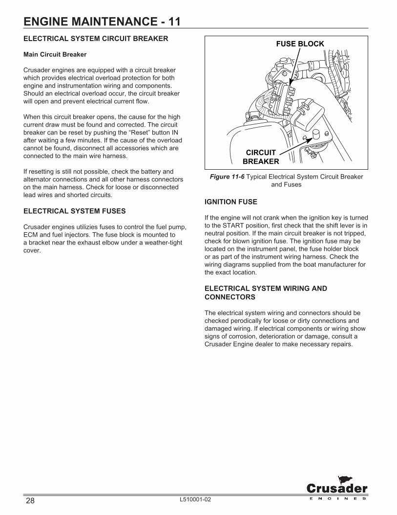
Crusader engines utilizies fuses to control the fuel pump, ECM and fuel injectors. The fuse block is mounted to a bracket near the exhaust elbow under a weather-tight cover.
Figure 11-6 Typical Electrical System Circuit Breaker and Fuses
IGNITION FUSE
If the engine will not crank when the ignition key is turned to the START position, fi rst check that the shift lever is in neutral position. If the main circuit breaker is not tripped, check for blown ignition fuse. The ignition fuse may be located on the instrument panel, the fuse holder block or as part of the instrument wiring harness. Check the wiring diagrams supplied from the boat manufacturer for the exact location.
ELECTRICAL SYSTEM WIRING AND CONNECTORS
The electrical system wiring and connectors should be checked perodically for loose or dirty connections and damaged wiring. If electrical components or wiring show signs of corrosion, deterioration or damage, consult a Crusader Engine dealer to make necessary repairs.
FUSE BLOCK
CIRCUIT
BREAKER

29L510001-02
ENGINE MAINTENANCE - 11BATTERY
WARNING
Battery electrolyte is a corrosive acid and should be handled with care. If electrolyte is spilled or splashed on any part of the body, IMMEDIATELY fl ush the exposed area with liberal amounts of water and obtain medical aid as soon as possible. Safety glasses and rubber gloves are recommended when handling batteries or fi lling with electrolyte.
WARNING
Hydrogen gases that escape from the battery when charging are highly explosive. Do not use jumper cables and a booster battery to start the engine. Do not recharge a weak battery in the boat. Remove the battery from the boat and recharge in a well ventilated area away from fuel vapors, sparks and open fl ames.
Follow maintenance instructions and warnings as supplied by the battery manufacturer. If this information is not available, follow these guidelines for the proper battery care.
• Do not operate the engine with an open in the battery circuit, as this may cause damage to the alternator. Make sure that all connections are clean and secure.
• When removing the battery cables, always remove negative (-) cable fi rst, and then remove the positive (+) cable. When installing battery cables, install the positive (+) cable fi rst, then install the negative (-) cable.
• Periodically check the battery for signs of corrosion, frayed battery leads or cracked case. Repair or replace as necessary.
• Periodically check the electrolyte level. Add distilled water to bring up to the proper levels.

30 L510001-02
ENGINE MAINTENANCE - 11FRESH-WATER COOLING SYSTEM SACRIFICIAL ZINC ANODE
Located in the raw water side of the heat exchanger is a zinc anode which is marked by a decal. To check, remove the plug and visually check the condition of the zinc rod. The length of the zinc rod when new is approximately 1.5 inches. If more than one half of the zinc is gone, replace with a new zinc anode.
Different geographic locations and water make-up can result in either high or low sacrifi cial requirements. A high rate of zinc anode consumption should also alert the owner to a possibility of an improperly wired boat accessory, which would require complete checking by qualifi ed service personnel.
Figure 11-7 Zinc Anode Location F.W.C. Heat Exchanger
FULL
ADD
P/N 23627
Remove and check condition of zinc pencil
every 30 days. Replace if more than 50%
missing with Crusader Part #10972.
HEAT EXCHANGER
PROTECTIVE ANODEZINC
ANODE

31L510001-02
ENGINE MAINTENANCE - 11CHECKING COOLANT LEVEL
WARNING
Do not remove cooling system fi ller cap when the engine is hot. Allow the engine to cool and then remove the pressure cap slowly, allowing the pressure to vent. Hot coolant, under pressure, may discharge violently and cause severe burns.
Coolant Recovery Resevoir
The “see-through” plastic reservoir is connected to the heat exchanger by a small hose. The recovery bottle col-lects coolant that expands with rising temperature, and would otherwise overfl ow from the system. Coolant level should be at or slightly above the “ADD” mark on the bottle when the system is cold. Coolant should be added ONLY to the reservoir when the system cools.
Coolant Filler Neck
Periodically, on a cool engine, remove the pressure cap from the fi ller neck to ensure the coolant recovery system is functioning properly. Coolant must be at the top of the fi ller neck. If coolant is low, check the gasket in the cap for damage. Replace if necessary. Inspect the coolant recovery system for leaks.
Figure 11-8 Checking Coolant Level
FULL
ADD
PRESSURE
CAPCOOLANT
RECOVERY
TANK

32 L510001-02
ENGINE MAINTENANCE - 11FLUSHING COOLING SYSTEM - SEA-WATER SECTION
To prevent silt and/or salt build-up in the cooling system (fresh or raw-water cooled), fl ush the sea-water section of the cooling system with fresh water at specifi ed intervals.
CAUTION
Do not operate the engine without water being supplied to the sea-water pump. The sea-water pump impeller may be damaged and subsequent overheating damage may result.
Figure 11-9 Typical Sea-Water Inlet
CAUTION
Do not run the engine above 1500 RPM when fl ushing. Suction created by the sea-water pump may collapse the fl ushing hose, causing the engine to overheat. Watch the temperature gauge while fl ushing to ensure the engine does not overheat.
INLET
HOSE
CLOSE
SEACOCK
BEFORE
REMOVING
INLET
HOSE
ATTACH
FLUSHING
ADAPTER
HERE

33L510001-02
ENGINE MAINTENANCE - 11TESTING COOLANT FOR ALKALINITY
It is recommended that the coolant in the fresh-water section be tested each year for alkalinity. Coolant that is not alkaline has lost the effectiveness of its rust inhibitors, which can lead to internal corrosion and cooling system problems. It is recommended to replace the standard ethylene glycol coolant in the system every two years to prevent a build-up of harmful chemicals within the fresh-water system.
1. Obtain red litmus paper from a local supplier (drugstore, laboratory, etc.).
2. Remove the pressure cap from the coolant fi ller neck and insert one end of the litmus paper into he coolant.
3. If red litmus paper turns blue, coolant is alkaline and does not need to be replaced. If the litmus paper remains red, the coolant is not alkaline and must be replaced.
DRAINING FRESH-WATER COOLING SYSTEM
NOTICE: To protect the environment, dispose of coolant properly. Check your local restrictions for proper disposal instructions of removed coolant.
NOTICE: Refer to cooling system water fl ow diagrams for drain locations.
1. Remove the following drain plugs to drain coolant from the fresh-water cooling system:
− Drain plug on heat exchanger
− The hose and/or drain plugs from the fi tting on the bottom of the exhaust manifolds (one on each side)
− Drain plugs from risers and elbows
− Drain plugs on the cylinder block (one on each side)
− Drain plug on oil cooler
− Drain plug on fuel cooler canister (returnless fuel system only)
2. Remove the large hose from the engine block water circulating pump.
3. After system has drained completely, coat all the drain plugs with PerfectSeal (or equivalent) and reinstall in the proper locations. Reinstall the hose(s) on the water circulating pump and the exhaust manifolds and tighten the clamps securely.

34 L510001-02
ENGINE MAINTENANCE - 11FILLING FRESH-WATER COOLING SYSTEM
A new extended life engine coolant known as DEX-COOL™ is used in your engine(s). It is imperative to note the following about DEX-COOL™ engine coolant:
• IT IS PINK IN COLOR TO DISTINGUISH IT FROM CONVENTIONAL COOLANT.
• THE SERVICE CHANGE INTERVAL ON ENGINES BUILT WITH DEX-COOL™ IS 5 YEARS.
• TO MAINTAIN FULL CORROSION PROTECTION DURABILITY, DEX-COOL™ MUST NOT BE MIXED WITH CONVENTIONAL (CONTAINING SILICATE) ENGINE COOLANTS.
• DEX-COOL™ IS AN ETHYLENE GLYCOL BASED PRODUCT, THEREFORE, BOIL AND FREEZE PROTECTION ARE MEASURED IN THE SAME FASHION AS CONVENTIONAL COOLANTS.
TO FULLY REALIZE ITS MANY ADVANTAGES, DEX-COOL™ MUST NEVER BE MIXED WITH CONVENTIONAL COOLANTS.
DEX-COOL™ can become contaminated by inadvertently topping-off with conventional coolant, adding conventional coolant to the system or even if fi ll/drain containers are shared between coolants. If contamination occurs, the cooling system must be immediately drained and fl ushed, and refi lled with DEX-COOL™. No short-term damage will occur, however, the service interval will be reduced from 5 years to 2 years.
The fresh-water cooling side of the cooling system must be fi lled with a 50/50 mixture of DEX-COOL™ (or equivalent, which meets GM6277M) extended life antifreeze and water solution.
IMPORTANT: More than 50% antifreeze solution can contribute to an overheating condition.
IMPORTANT: If the engine is being placed in winter storage, the fresh-water cooling section must be fi lled with a correct type of coolant and water solution, properly mixed, to protect the engine to the lowest temperature to which it will be exposed.
1. Make sure that all drain plugs are properly installed.
2. Remove the pressure cap from the fi ller riser, located on the intake manifold.
3. Fill the system with antifreeze solution until the system is fi lled. See ENGINE FLUID CAPACITIES for system capacities.
Figure 11-10 F.W.C. Fill Riser Location
FULL
ADD
FILL
RISER
Figure 11-11 Filling F.W.C. System
FULL
ADD
ANTIFREEZE
SOLUTION
4. Start the engine and operate at idle speed (800-1000 RPM) to purge any air from the system. When the coolant level remains constant in the fi ller riser, install the pressure cap on the riser.
5. Add additional coolant into the coolant recovery tank to the “ADD” level.
6. Continue to run the engine until it reaches normal operating temperature. Check the coolant recovery tank for the proper level and add coolant if necessary.

35L510001-02
ENGINE MAINTENANCE - 11CLEANING SEA-WATER SECTION OF HEAT EXCHANGER - FRESH-WATER COOLED MODELS ONLY
The sea-water section of the heat exchanger should be cleaned whenever there is a noticeable decrease in cooling effi ciency. You may use the following procedure for cleaning, or, if the build-up of scale and mineral deposits is heavy, it is recommended that the heat exchanger be removed and taken to a repair facility to be boiled out (such as a radiator repair facility).
1. Remove the bolts securing the heat exchanger end plates. Remove the end plates and gaskets.
2. Clean the water passages in the heat exchanger by inserting a suitable-size wire brush into each passage. Use compressed air to blow out loose particles.
3. Clean the gasket surfaces on the end plates and the heat exchanger. Apply PerfectSeal to both sides of the new gaskets. Install the end plates and the new gaskets onto the heat exchanger. Install the bolts and tighten securely.
4. Start the engine and inspect for leaks.
Figure 11-12 Heat Exchanger and End Plate Removal
HEAT
EXCHANGER
THERMOSTAT
HOUSING
COOLANT
DRAIN PLUG
RAW WATER
DRAIN PLUG
GASKET
PLATEBOLT

36 L510001-02
WARNING
Extreme caution must be exercised when servicing the fuel system and/or replacing fuel fi lter. Gasoline is extremely fl ammable and highly explosive under certain conditions. Be sure the ignition key is off and do not smoke or allow open fl ame in the area while servicing. Wipe up any spilled fuel immediately.
WARNING
Extreme caution must be exercised when servicing the fuel system. The fuel system operates under high pressure. Use caution when removing or replacing components, as residual pressure may be present.
WARNING
Make sure that there are no fuel leaks before closing the engine hatch.
ENGINE MAINTENANCE - 11FUEL SYSTEM DESCRIPTION Crusader Engines will be equipped with one of two fuel
systems: the Fuel Control Cell (FCC), or the “Returnless-Type.”
The “Return-Type” fuel system is best described as having a fuel feed line coming from the fuel tank and fuel line that returns unused fuel back to the fuel tank.
The “Returnless-Type” fuel system requires a fuel feed line to supply fuel. Unused fuel is circulated through a cooler and is eventually returned to the fuel feed line.
Fuel Control Cell (FCC) Fuel System
The Fuel Control Cell (FCC) eliminates vapor lock and air ingestion caused by fuel tank slosh, and provides the necessary fi lteration and water separation.
The FCC incorporates two (2) fuel pumps to provide an uninterrupted fl ow of fuel to your Crusader marine engine. Fuel is fed into the FCC bowl by a low-pressure, high-volume electric fuel pump. This pump fl ows fuel at a volume much greater than the fuel fl ow rate required of the high-pressure pump and engine demands. The high-pressure pump, mounted inside the FCC bowl, provides the necessary fuel pressure and volume to maintain proper engine performance. The FCC constantly has an ample supply of fuel to meet the idle, cruise and acceleration fuel requirements of the engine.
The fuel pressure regulator, located on the fuel rail, controls the fuel pressure, and maintains a constant pressure across the the fuel delivery system. Excess fuel, not used by the engine, returns to the FCC bowl.
The fuel delivered to the engine by the FCC is fi ltered by a fi lter and water separator element, which surrounds the high pressure pump inside the FCC bowl.
As indicated above, fuel enters the FCC bowl from two (2) locations, the low-pressure pump (initial input) and the fuel return line from the fuel pressure regulator (unused, recirculating fuel). Fuel exits the FCC bowl at two (2) locations, the high-pressure output to the fuel injection system and all excess fuel in the FCC bowl is routed back to the tank via the return line.
WARNING
Visually inspect unit for fuel leaks before operating the engine. If fuel leaks are present, DO NOT operate the engine, contact your service center immediately.

37L510001-02
ENGINE MAINTENANCE - 11
Figure 11-13 Fuel Control Cell (FCC) Fuel System (Typical)
FUEL
SUPPLY
INLET
PRIMARY
FUEL
FILTER
FUEL
SUPPLY
LINE
FUEL
RETURN
LINE
FUEL
CONTROL
CELL
LOW-PRESSURE
FUEL PUMP
Servicing the FCC
The frequency of draining the water or replacing the fi lter element is determined by the contamination level of the fuel. Replace the fi lter element at least once a year, or when a loss of power is noticed (whichever occurs fi rst).
WARNING
Improper use, installation or servicing may cause an explosion or fi re resulting in bodily injury, or death. This unit should only be serviced by a qualifi ed technician. Read and follow all instructions before proceeding. Run the engine and check for fuel leaks after installation, element replacement or draining the bowl. DO NOT remove the FCC bowl unless servicing the fi lter element, otherwise contamination or bowl O-ring swelling may result.

38 L510001-02
ENGINE MAINTENANCE - 11
Figure 11-14 Fuel Control Cell (FCC)
FUEL
DRAIN
FUEL
BOWL
FUEL
FILTER
FUEL
PUMP
"O"- RING
Draining the FCC Bowl, ENGINE OFF
1. Disconnect the two-wire electrical connector.
2. Hold the 3/4” jam nut, located at the bottom of the FCC bowl, with a wrench. Remove the 7/16” plug, and drain the bowl contents into an approved container.
CAUTION: Both fuel and water will drain from the FCC bowl.
3. Apply pipe sealant, suitable for use with gasoline, to the threads of the 7/16” plug.
4. Tighten the 7/16” plug while holding the 3/4” jam nut with a wrench.
5. Reconnect the two-wire electrical connector.
6. Cycle the ignition key several times to run the electric fuel pumps and fi ll the FCC bowl with fuel. Inspect the drain plug area for leaks. Correct any leaks prior to operating the engine.
7. Start the engine and inspect for fuel leaks. Correct any leaks prior to operating the engine any further.
Filter Element Replacement, ENGINE OFF
1. Disconnect the two-wire electrical connector.
2. Hold the 3/4” jam nut, located at the bottom of the FCC bowl, with a wrench. Remove the 7/16” plug, and drain the bowl contents into an approved container.
CAUTION: Both fuel and water will drain from the FCC bowl.
3. Using a strap-type oil fi lter wrench, remove the FCC bowl by turning it counterclockwise as view from the bottom.
4. Slide the bowl downward over the suspended fi lter element. It may be necessary to pull the unit to one side in order to remove the FCC bowl.
5. Remove the fuel fi lter element from the suspended pump by gripping the fuel pump with one hand, and pulling the fi lter element downward with the other hand.
6. Push on new fi lter element (part number RP080026) over the electric fuel pump.
7. Using a pick made of soft material, such as a toothpick, remove the old O-ring from the inside of the FCC bowl mounting head.
CAUTION: The mounting head O-ring groove may be damaged by using sharp steel tools to remove this O-ring.
8. Lubricate the new O-ring with a light grease and install the new O-ring into the FCC bowl mounting head.
9. Apply pipe sealant, suitable for use with gasoline, to the threads of the 7/16” plug.
10. Install and tighten the 7/16” plug while holding the 3/4” jam nut with a wrench.
11. Grease taper and the threads on the FCC bowl and, by hand, thread the FCC bowl into the FCC mounting head. Tighten the bowl fi rmly back into the mounting head with an oil fi lter wrench.
12. Reconnect the two-wire electrical connector.
13. Cycle the ignition key several times to run the electric fuel pumps and fi ll the FCC bowl with fuel. Inspect the drain plug area for leaks. Correct any leaks prior to operating the engine.
14. Start the engine and inspect for fuel leaks. Correct any leaks prior to operating the engine any further.
DO NOT ATTEMPT TO SERVICE ANY OTHER PARTS ON THIS UNIT.

39L510001-02
Figure 11-15 Returnless-Type Fuel System (Typical)
Primary Fuel Filter
Dependent upon application, the primary fuel fi lter may be located at the front of the engine, rear of the engine on the transmission housing or next to the eletric fuel pump. This fi lter fi lters the fuel before it reaches the fuel pump.
1. Close the fuel supply line (shut-off valve). Start the engine and let it run until it stalls from lack of fuel.
2. Turn ignition key OFF.
NOTICE: A rag should be placed under the fi lter to absorb any spilled fuel. Remove the bracket from the block for servicing.
3. Remove the nut and washer that secures both halves of the fi lter housing. Separate the housing.
4. Remove the fi lter/seal assembly. Clean with soap and water.
5. Inspect the fi lter screen and rubber seal for any signs of damage. Replace as necessary.
ENGINE MAINTENANCE - 11
WARNING
Extreme caution must be exercised when servicing the fuel system. The fuel system operates under high pressure. Use caution when removing or replacing components, as residual pressure may be present.
FUEL
SUPPLY
INLET
PRIMARY
FUEL
FILTER
FUEL
SUPPLY
LINE
FUEL
RETURN
LINE
WATER
SEPARATING
FUEL FILTER
FUEL
COOLER
CANISTER
ELECTRIC
FUEL PUMP

40 L510001-02
6. Reinstall fi lter/seal assembly into the housing halves. Make sure the seals are aligned properly. Install the nut and washer.
7. Open fuel shut-off valve.
8. Prime the fuel system. Refer to procedures in this section.
9. Turn the key to START position and crank the engine until it starts, or 30 seconds elapse.
10. Repeat step 8 if the engine fails to start.
11. After the engine starts, check for leaks and repair as necessary.
ENGINE MAINTENANCE - 11
WARNING
Make sure there are no fuel leaks before closing the engine hatch.
Priming Fuel System
To prime the fuel system, cycle the ignition key 3 times using the following procedures:
1. Turn ignition key to ON position for 5 seconds.
2. Turn ignition key OFF.
3. Pause for 10 seconds.
4. Repeat steps 1-3 three times.
Crank the engine until it starts or 30 seconds elapse. If the engine does not start, repeat the priming procedures.
FLAME ARRESTOR
At specifi ed intervals, the fl ame arrestor should be checked for blockage caused by dirt or other foreign material.
Loosen the clamp securing the fl ame arrestor to the air intake tube or throttle body. Remove the fl ame arrestor. Clean the fl ame arrestor with solvent and dry with compressed air. Reinstall the fl ame arrestor and tighten the clamp(s) securely.
Figure 11-16 Flame Arrestor - 5.7L (Typical)
Figure 11-17 Flame Arrestor - 8.1L (Typical)
FLAME
ARRESTOR
FASTENERS
THROTTLE
BODY
FLAME
ARRESTOR
CLAMP
(NOT SHOWN)
FLAME
ARRESTOR
THROTTLE
BODY

41L510001-02
8.1L ACCESSORY DRIVE BELT
The Crusader 8.1L engine uses a single serpentine belt to drive the engine water circulation pump and the alternator. The sea-water pump is mounted onto the crankshaft pulley and is driven directly by the crankshaft.
Figure 11-18 8.1L Accessory Drive Belt Confi guration
ENGINE MAINTENANCE - 11
DRIVE BELT INSPECTION
Inspect the drive belt for excessive wear, shredding or missing sections.
Inspect the drive belt for contamination from excessive dirt, oil, coolant or other substances that may effect the drive belt operation.
If a problem is found, replace the belt after inspecting the following items:
• The engine water circulation pump and alternator pulleys for signs of misalignment
• The engine water circulation pump and alternator pulleys for signs of rust or other damage
• Bent pulleys or tight bearings in the engine water circulation pump and alternator
CAUTION
The replacement of the drive belt requires the removal of the inlet hose from the sea-water pump. With the hose removed, it is possible for water to enter the bilge of the boat, and possibly sink it. ALWAYS plug the inlet hose securely to prevent this possibility from occurring.
DRIVE BELT REPLACEMENT
1. Remove the inlet and outlet hoses from the sea- water pump, being careful not to allow the hose clamps to fall into the bilge.
2. Remove the bolt and washers that attach the sea-water pump to the bracket, being careful not to allow the bolt and washers to fall into the bilge.
3. Loosen the bolts that attach the bracket to the engine block until a gap, large enough to pass the belt through, is created.
4. Note the routing of the belt before removing.
5. Using a 15 mm box wrench or socket, turn the belt tensioner to relieve the tension on the belt. Slide the belt off of the pulleys and through the gap between the sea-water pump and the bracket. Release the tensioner slowly to prevent the tensioner from snapping against its stop, and possibly causing damage to the tensioner.
Figure 11-19 Belt Tensioner (8.1L)
5. Slide the new belt through the gap between the sea-water pump and the bracket. Slide the belt onto the pulleys using the same routing as noted prior to removal.
CIRCULATION
PUMP PULLEY
CRANKSHAFT
PULLEY
BELT
TENSIONER
IDLER
PULLEY
CIRCULATION
PUMP AND
ALTERNATOR
DRIVE BELT
ALTERNATOR
PULLEY

42 L510001-02
6. Compress the belt tensioner, and slide the belt over the tensioner pulley. Release the tension slowly to tension the belt.
7. Position the bracket onto the sea-water pump anchor boss, and install the fl at washer, lock washer and bolt to the pump.
8. Tighten the bracket-to-engine block attaching bolts to 18 lb. ft.
9. Tighten the bolt that secures the sea-water pump to the bracket to 12 lb. ft.
10. Install the inlet and outlet hoses to the sea-water pump. Position the hoses and clamps so that the clamps are clamping on the pump side of the fi tting bead. Tighten the clamps securely.
WARNING
Engine must be shut OFF and the ignition key removed before inspecting the drive belt(s). The drive belt(s) should be checked periodically for condition and tension. If the belt(s) shows signs of cracking, glazing or deterioration, replace with new belt(s).
ENGINE MAINTENANCE - 11
ACCESSORY DRIVE “V”- BELT (5.7L ENGINE)
Check the drive belt tension by pressing down on the belt midway between the engine circulating pump pulley and the alternator pulley. The belt should depress 1/2 in. (13 mm). If depression is more than allowable, adjust the tension by loosening the alternator adjustment bolt and the pivot bolt. Apply required pressure with a pry bar to tighten the belt tension. While maintaining pressure, tighten the alternator adjusting bolt securely. Tighten the pivot bolt.
Figure 11-20 Drive Belt Location and Adjustment (5.7L)
RAW WATER
PUMP
ALTERNATOR
BELT
ADJUSTMENT
BOLT
1/2"
DEFLECTION

43L510001-02
ENGINE MAINTENANCE - 11CHANGING OILS
WARNING
IMPORTANT: The Federal Water Pollution Control Act prohibits the discharge of oil or oily waste into or upon the navigable waters and continuous zone of the United States, if such discharge causes a fi lm or sheen upon, or discoloration of the surface of the water, or causes sludge or emulsion beneath the surface of the water. Violators are subject to a penalty of $5,000.00.
Refer to the MAINTENANCE SCHEDULE for oil change intervals. The engine and transmission oils should be changed prior to placing the boat into storage.
The transmission oil change should be performed by an authorized dealer, at specifi ed intervals.
IMPORTANT: Change the engine oil when the engine is warm from operation. Warm oil fl ows more freely, and allows more foreign material and impurities to be removed.
On the 8.1L engine, the engine oil fi lter is remote mounted. The engine block location, where the fi lter is normally mounted, is covered with an oil fi lter bypass adapter. DO NOT remove this adapter when changing the oil.
1. With the engine at normal operating temperature, remove the dipstick and install a crankcase oil pump onto the dipstick tube (Figure 11-19). Insert the discharge hose into a suitable container. Pump the oil from the engine until the crankcase is empty. Remove the oil pump from the dipstick tube.
2. Remove the oil fi lter by turning it counterclockwise, using an oil fi lter wrench if necessary. Discard the old fi lter and sealing ring.
3. Coat the sealing ring, on the new fi lter, with a light coating of clean engine oil. Install the oil fi lter securely by hand. DO NOT overtighten.
4. Fill the engine with the recommended oil, see OIL REQUIREMENTS, through the oil fi ll location on the valve cover (Figure 11-22).
Figure 11-21 Engine Oil Removal
Figure 11-22 Engine Oil Fill (8.1L)
5. Start the engine and operate for 5 minutes to circulate the oil throughout the engine. Check entire system for leaks, especially around the oil fi lter.
6. Stop the engine and wait 5 minutes to allow the oil to completely drain down. Check the oil level and add oil, if needed, to bring the engine oil to the proper level.
OIL FILL
CAP
OIL PUMP
CONTAINER
DIPSTICK

44 L510001-02
ENGINE MAINTENANCE - 11ENGINE ALIGNMENT
CAUTION
Engine must be properly aligned, or vibration, noise and damage to the transmission output shaft oil seal and bearings may result.
IMPORTANT: Engine alignment MUST BE RECHECKED with the boat in the water, fuel tanks full and with a normal load on the boat. Engine must be aligned so that the transmission and the propeller shaft coupling center lines are aligned, and coupling faces are parallel within 0.003 in. (0.07 mm). This applies to installations with solid couplings, as well as fl exible couplings.
1. Check the mating surfaces on the transmission and the propeller shaft couplings. Make sure they are clean and fl at.
Figure 11-23 Shaft Mating Surface Check - 8 Degree Down Angle
Figure 11-24 Shaft Mating Surface Check - “V” Drives
2. Center the propeller shaft in the shaft log as follows:
• Push down and then lift the propeller shaft as far as it will move, then place the shaft in the middle of the movement.
• Move the shaft to the port and then to the starboard as far as the shaft will move, then place the shaft in the middle of the movement.
• With the propeller shaft in the middle of the shaft log, align the engine to the shaft.
3. Check that the coupling center lines align by butting the propeller shaft coupling against the transmission coupling. The shoulder on the propeller shaft coupling face should engage recessed on the transmission coupling face, with no resistance.
NOTICE: Some propeller shaft couplings may not have a shoulder on the mating surface. On these installations, use a straight edge to check the centerline alignment.

45L510001-02
ENGINE MAINTENANCE - 11
Figure 11-25 Centering Propeller Shaft - 8 Degree Down Angle
4. Check for any angular misalignment. Hold coupling faces tightly together and check for a gap between the coupling faces, with a 0.003 in. (0.07 mm) feeler gauge, at 90-degree intervals.
Figure 11-26 Angular Alignment - 8 Degree Down Angle
Figure 11-27 Angular Alignment - “V” Drives

46 L510001-02
ENGINE MAINTENANCE - 11
Figure 11-29 Engine Extension
IMPORTANT: The large diameter of the mount trunnion MUST NOT extend over 1.0 in. (25.4 mm) from the mounting brackets on any of the mounts.
6. After the engine has been properly aligned, secure the engine mounts.
7. Connect the propeller shaft coupling to the transmission coupling. Tighten the coupling attaching bolts and nuts to the correct specifi cations.
FASTENER TORQUE SPECIFICATIONS
Figure 11-28 Engine Mount Adjustment
5. If the coupling center lines are not aligned, or if the coupling faces are more than 0.003 in. (0.07 mm) out of parallel, adjust the engine mounts as follows:
• UP or DOWN ADJUSTMENT: Loosen the lag bolt 1/4 turn. Use the mount adjusting tool or a 3/8 in. (0.95 cm) or 1/2 (1.27 cm) diameter rod through both sides of the adjusting sleeve to turn. Turn the adjusting sleeve in the direction required to raise or lower the engine. After the adjustment is complete, tighten the lag bolt.
IMPORTANT: Both the front mount (or rear mount) adjusting sleeves must be turned equally to keep the engine level from side to side.
• LEFT or RIGHT ADJUSTMENT: Loosen the trunnion clamping bolt and the nut on all four mounting brackets. Move the engine to the left or right, as necessary, to obtain the proper alignment.
Location Lb-Ft (N.m)
Engine Mount to Stringer Securely
Propeller 50 (68)
Trunnion Bolts 45 (61)
ROD
LOWER
ENGINE
RAISE
ENGINE
TRUNNION
BOLT
1.0 in. MAX
(25 mm)
LAG
BOLTS

47L510001-02
ENGINE MAINTENANCE - 11
ENGINE MAINTENANCE LOG Operating Date Maintenance/Repair Hours

48 L510001-02
ENGINE MAINTENANCE - 11MAINTENANCE SCHEDULE
After 1st Every 50 Every 100 Location and Service Check 25 Hrs of Hours of Hours of Once Daily Operation Operation Operation Each Year
Check coolant level - Fresh-water cooled models only X
Check oil level - Engine crankcase X
Check oil level - Transmission X
Engine Assembly (complete - Check for obvious leaks (water, oil, fuel and exhaust) X
Remote Control and Steering System - Check for proper operation X
Sea Strainer - Check (if equipped) X
Cooling System - Check condition and tightness of all hose clamps X X1 X
Drive Belt - Inspect condition and check tension X X X
Exhaust System - Check condition and tightness of all hose clamps X X1 X
Ignition System and Spark Plugs - Clean and inspect condition O O O
Engine Assembly (complete) - Check for loose, missing or damaged parts (especially engine mounts, starter and alternator mounting fasteners) X X X
Change engine oil and fi lter X X X
Engine Alignment - Check and adjust if necessary O O
Ignition Timing - Not Adjustable
Battery - Check electrolyte level and specifi c gravity. Inspect case for damage. Check cables and connections. X X X
Electrical System (complete) - Check for loose or dirty connections and damaged wiring X2 X
Flame Arrestor and Crankcase Ventilation System - Clean and inspect X X

49L510001-02
ENGINE MAINTENANCE - 11MAINTENANCE SCHEDULE (cont’d)
After 1st Every 50 Every 100 Location and Service Check 25 Hrs of Hours of Hours of Once Daily Operation Operation Operation Each Year
Hoses (all) - Inspect for cracks, swelling, weather checking or other signs of deterioration X X
Shift and Throttle Cable Linkage - Inspect and lubricate (A) X1 X
Fuel Filters - Service or replace O O
Transmission and “V” Drive - Change O fl uid (B,C) and clean strainer, if equipped Hurth Only O
MAINTENANCE SCHEDULE (cont’d)
Fresh-water cooled models - Clean sea-water section As required 3 (X)
Fresh-water cooled models - Check coolant for boil/freeze protection At least once each year (X)
Fresh-water cooled models - Change coolant Every fi ve years
Zinc Anodes - Heat exchanger and cooler - check condition Every 30 days 3 (X)
Engine Assembly Exterior Surfaces - spray with rust- Fresh water areas - Every 60 days (X) preventative oil (D) Salt water areas - Every 30 days (X)
Cooling System (SALT WATER AREAS ONLY) - Flush sea-water section After use each day (X)
Notes:
(X) Denotes service to be performed by the owner/operator
(O) Denotes service to be performed by an authorized Crusader Engines dealer
(A) Use SAE 30 engine oil
(B) All Velvet Drive and Hurth transmissions - Use Dexron III automatic transmission fl uid
(C) All Velvet “V” Drive transmissions - Use Dexron III automatic transmission fl uid
All Walters “V” Drive transmissions - Use Exxon Spartan EP-68 or SAE 30 engine oil
All Crusader “V” Drive transmissions - Use SAE 80W-90 gear oil(D) Use WD-40 penetration oil or equivalent
1 In fresh-water areas, every 100 hours of operation or 120 days (whichever occurs fi rst). In salt-water areas, every 50 hours of operation or 60 days (whichever occurs fi rst).
2 In fresh-water areas, every 50 hours of operation or 60 days (whichever occurs fi rst). In salt-water areas, every 25 hours of operation or 30 days (whichever occurs fi rst).
3 Requires more frequent inspection if used in extremely salty, polluted or mineral-laden waters.

50 L510001-02
VISUAL INSPECTION
It is important for the owner/operator to visually inspect the complete engine assembly at regular intervals. Most often, costly repairs can be avoided if potential problems are corrected before there is a failure.
Inspect the complete engine assembly for obvious fuel, oil, water or exhaust leaks. Check for loose, damaged or missing parts. Check all hose clamps for adequate tightness. Check the electrical system for loose or dirty connections or damaged wiring.
Touch up scratches, nicks and corrosion damage to the exterior fi nish of the engine. Spray paint may be obtained from your local Crusader Engines dealer.
Protect engine fi nish from corrosion by periodically spraying the engine exterior fi nish with a rust preventative oil (such as WD-40).
ENGINE MAINTENANCE - 11
ENGINE FLUID CAPACITIES
TRANSMISSION FLUID CAPACITIES
Model MP 5.0 / 5.7L MP 8.1L
Crankcase Oil Capacity W / New Filter Aluminum Pan 6 Quarts (4.73 - 6.62 L)1 7 Quarts (6.62 - 9.51L)1
Stamped Steel Pan 4 Quarts (4.73 - 6.62 L)1 N/A
Fresh Water Cooling System Capacity 23 Quarts (231.77 L) 33 Quarts (31.23 L)
Model All Models Type
Velvet Drive, 1:1 Ratio 1,2 2.5 Quarts (2.37 L) DEXRON III
Velvet Drive, 1:52 - 2.91:1 Ratio 1,2 3.5 Quarts (3.31 L) DEXRON III
Velvet Drive, V-Drive (exc. 5000), All Ratios 1,2 4.5 Quarts (4.26 L) DEXRON III
Velvet Drive 5000 (exc. V-Drive), All Ratios 1,2 3.0 Quarts (2.37 L) DEXRON III
Velvet Drive 5000 V-Drive, All Ratios 1,2 4.5 - 5.0 Quarts (4.26 - 4.73 L) DEXRON III
Hurth (Exc. V-Drive), All Ratios 1,2 4.0 Quarts (3.79 L) DEXRON III
Hurth V-Drive, All Ratios 1,2 4.5 - 5.0 Quarts (4.26 - 4.73 L) DEXRON III
Walters RV-36D V-Drive 1.5 Quarts (1.42 L) SAE 30
1 - Capacities are dependent on installation angle. ALWAYS use the dipstick to determine the exact quantity of oil required. Add the correct amount of oil to fi ll to the “FULL” mark on the oil level dipstick. 2 - Check the transmission fl uid level at operating temperature and immediately after shutdown of the engine.
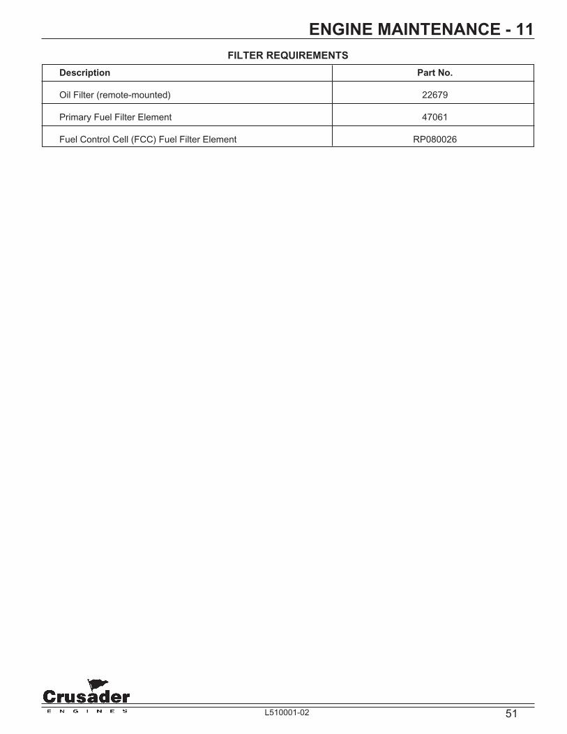
51L510001-02
ENGINE MAINTENANCE - 11FILTER REQUIREMENTS
Description Part No.
Oil Filter (remote-mounted) 22679
Primary Fuel Filter Element 47061
Fuel Control Cell (FCC) Fuel Filter Element RP080026

52 L510001-02
ENGINE SPECIFICATIONS - 12
MODEL MP 5.0L MP 5.7L MP 8.1L (STD) MP 8.1L (HO) (Horsepower) (275 HP) (330 HP) (385 HP) (425 HP)
Displacement 5.0L (305 CID) 5.7L (350 CID) 8.1L (496 CID) 8.1L (496 CID)
Bore 3.75 in. (95.0 mm) 4.0 in. (101.6 mm) 4.25 in. (107.95 mm) 4.25 in. (107.95 mm)
Stroke 3.48 in. (88.3 mm) 3.48 in. (88.3 mm) 4.370 in. (111.0 mm) 4.370 in. (111.0 mm)
Compression Ratio 9.4:1 9.4:1 9.1:1 9.1:1
Compression Pressure 130 - 160 psi 130 - 160 psi 130 - 160 psi 130 - 160 psi (896 - 1103 kPa) (896 - 1103 kPa) (896 - 1103 kPa) (896 - 1103 kPa)
WOT Operating RPM 4200 - 4600 4800 - 5000 4200 - 4600 4400 - 5000
Cruising RPM (Max) 3600 3800 3600 3800
Idle RPM (In Gear) 650 (Not Adjustable) 650 (Not Adjustable) 650 (Not Adjustable) 650 (Not Adjustable)
Oil Pressure @ 25 - 60 psi 25 - 60 psi 25 - 60 psi 25 - 60 psi 2000 RPM (172 - 414 kPa) (172 - 414 kPa) (172 - 414 kPa) (172 - 414 kPa)
Minimum Oil Pressure 10 psi (69 kPa) 10 psi (69 kPa) 10 psi (69 kPa) 10 psi (69 kPa) at Idle at Idle at Idle at Idle Fuel Pressure 55-62 psi 55-62 psi 34-47 psi 34-47 psi (379-427 kPa) (379-427 kPa) (234-325 kPa) (234-325 kPa)
Thermostat RWC 160˚F (61.7˚C) RWC 160˚F (61.7˚C) RWC 160˚F (61.7˚C) RWC 160˚F (61.7˚C) FWC 170˚F (76.7˚C) FWC 170˚F (76.7˚C) FWC 170˚F (76.7˚C) FWC 170˚F (76.7˚C)
Electrical System 12 Volt Negative (-) 12 Volt Negative (-) 12 Volt Negative (-) 12 Volt Negative (-) Ground Ground Ground Ground
Alternator Rating 70 Amps 70 Amps 70 / 100 Amps 70 / 100 Amps
Battery Rating 650 CCA (Minimum) 650 CCA (Minimum) 650 CCA (Minimum) 650 CCA (Minimum) 120 Ah 120 Ah 120 Ah 120 Ah
ENGINE SPECIFICATIONS

53L510001-02
ENGINE SPECIFICATIONS - 12
Figure 12-1 V-8 Firing Orders
17
c
64
28
35
1
3
5
7
2
4
6
8
1
3
5
7
2
4
6
8
5.0 / 5.7 LiterLH ROTATION
FRONT
8.1 LiterLH ROTATION
FRONT
NODISTRIBUTOR
FIRING ORDER:1-8-4-3-6-5-7-2
FIRING ORDER:1-8-7-2-6-5-4-3
FLYWHEEL END OF ENGINEALL V-8 MODELS
Rotation
TUNE-UP SPECIFICATIONS
Model MP 5.0L (275 HP) / MP 5.7L (330 HP) MP 8.1L(STD)/MP 8.1L (HO)
Spark Plug Type AC - MR43LTS Denso - TJ14R-P15
Spark Plug Gap 0.045 in. (1.14 mm) 0.060 in. (1.52 mm)
Timing @ 1000 RPM Fixed, Not Adjustable Fixed, Not Adjustable
Firing Order 1-8-4-3-6-5-7-2 1-8-7-2-6-5-4-3 (LH Rotation) (LH Rotation)

54 L510001-02
OUT-OF-SEASON STORAGE - 13ENGINE STORAGE
IMPORTANT: This service should be performed by an Authorized Crusader Dealer.
CAUTION
Refer to FLUSHING COOLING SYSTEM before proceeding.
1. Fill the fuel tanks with gasoline (that does not contain alcohol) and add a suffi cient amount of gasoline stabilizer, such as STA-BIL™ fuel stabilizer, to prevent the formation of fuel gum and varnish. Follow the instructions on the container.
IMPORTANT: If the boat is to be place into storage with fuel containing alcohol in the fuel tanks, the engine fuel systm must be run dry at idle RPM. Fuel tanks should be drained completely and fuel conditioner, such as STA-BIL™, added to any fuel remaining in the tanks.
2. Run the engine and allow it to reach normal operating temperature. Shut down the engine and change the oil and oil fi lter (See ENGINE MAINTENANCE).
3. Flush the cooling system if operating in salt water or brackish water areas. (See ENGINE MAINTENANCE).
NOTICE: If the engine is equipped with the optional fresh-water cooling system, refer to draining and refi lling procedures. The fresh-water cooling system must be serviced before fogging the engine for storage.
WARNING
Operate the bilge blower and be sure no fuel vapors are present when treating the engine. Be sure the engine compartment is well-ventilated to prevent a potential fi re hazard.
4. Remove the fl ame arrestor and start the engine. Operate the engine at a fast idle speed (1000-1500 RPM). Use an aerosol-type fogging solution and spray suffi cient amount, into the throttle body assembly bores, to treat internal surfaces of the engine. Refer to the instructions on the fogging solution canister. Turn the ignition switch to the OFF position.
5. Clean the fl ame arrestor and the vent hoses, and reinstall on the engine. Cover the throttle body assembly ,to prevent the possibility of the water entering the engine through the throttle body assembly, during storage.
6. Close the fuel shut-off valve (if equipped).

55L510001-02
OUT-OF-SEASON STORAGE - 13DRAINING INSTRUCTIONS
CAUTION
If the boat is to remain in the water during or after draining, close the seacock to prevent a siphoning action that may occur, allowing sea water to fl ow from drain holes or removed hoses.
IMPORTANT: When removing the drain plugs, insert a wire into the hole to remove any obstruction which would prevent water from draining completely.
RAW-WATER COOLED MODELS
1. Remove all the drain plugs from the following locations:
• Cylinder Block - one on each side (5.0/5.7L engines, remove the knock sensor on the port side)
• Exhaust Manifolds - remove hoses and/or drain plugs, one on each side
• Exhaust Elbows - two on each side
• Exhaust Risers - two on each side (if equipped)
• Transmission and Engine Cooler - one drain plug
2. Remove the hose from the inlet side of the sea- water pump.
3. Remove the large hose from the engine circulating pump, or drain plug (if equipped).
NOTICE: It may be necessary to bend or lift the hoses to allow water to drain completely.
4. Crank the engine over once to purge any trapped water in the sea-water pump. DO NOT allow the engine to start.
5. After the water has completely drained, coat the threads of the drain plugs with PerfectSeal (or equivalent), and reinstall in the proper locations. Reinstall all the hoses and tighten the clamps securely.
NOTICE: For additional protection against freezing and corrosion, you may wish to fi ll the engine with antifreeze. If ethylene glycol based antifreeze is used, check with local environmental agencies about the proper disposal of antifreeze. It may be necessary to drain the system prior to re-commissioning the boat.
6. Remove the hoses which connect to the exhaust manifolds from the thermostat housing.
7. Remove the large circulating pump hose from the thermostat housing. Pour the mixture of antifreeze and water, properly mixed to protect the engine to the lowest temperatures that it will be exposed to, into the circulating pump hose and fi ill the engine block. Pour additional antifreeze solution into the hoses connected to the exhaust manifolds.
8. Reinstall the hoses into the thermostat housing and tighten the hose clamps securely.
After draining is completed, perform the additional required maintenance as outlined in the MAINTENANCE SCHEDULE under ONCE EACH YEAR.
Figure 13-1 Draining Engine Circulating Pump (5.0/5.7L)
Remove large HOSE, or DRAIN PLUG (if equipped)

56 L510001-02
OUT-OF-SEASON STORAGE - 13
CAUTION
A discharged battery can be damaged by freezing.
FRESH-WATER COOLED MODELS
IMPORTANT: The fresh-water section of the cooling system must be kept fi lled year around with recommended coolant. Make certain that the cooling system is protected with an ethylene glycol antifreeze mixture properly mixed to protect the engine to the lowest temperature that it will be exposed to.
See DRAINING FRESH-WATER COOLING SYSTEM in ENGINE MAINTENANCE section for draining and refi lling procedures of FWC system, if required.
IMPORTANT: Drain sea-water section of the cooling system only.
1. Remove all the drain plugs from the following locations:
• Heat Exchanger - one on outboard side
• Exhaust Manifolds - remove hoses and/or drain plugs, one on each side
• Exhaust Elbows - two on each side
• Exhaust Risers - two on each side (if equipped)
• Transmission and Engine Cooler - one drain plug
• Fuel Cooler Canister (Returnless Fuel System Only) - one drain plug
2. Remove the hose from the inlet side of the sea- water pump.
3. Crank the engine over once to purge any trapped water in the sea-water pump. DO NOT allow the engine to start.
4. After the water has completely drained, coat the threads of drain plugs with PerfectSeal (equivelant), and reinstall in the proper locations. Reinstall the hoses and tighten all the clamps securely.
After draining is completed, perform the additional required maintenance as outlined in the MAINTENANCE SCHEDULE under ONCE EACH YEAR.
BATTERY STORAGE
Follow the battery manufacturer’s instructions for storage. If not available, use the following instructions:
• Remove the battery from the boat and clean, removing dirt and grease from the top of the battery.
• Fill the battery with distilled water to the manufacturer’s specifi cations.
• Store the battery in a cool, dry place. Do not store on a concrete surface.
• Periodically (every 30 to 45 days), check the water level and recharge the battery to the manufacturer’s specifi cations. Do not fast charge.
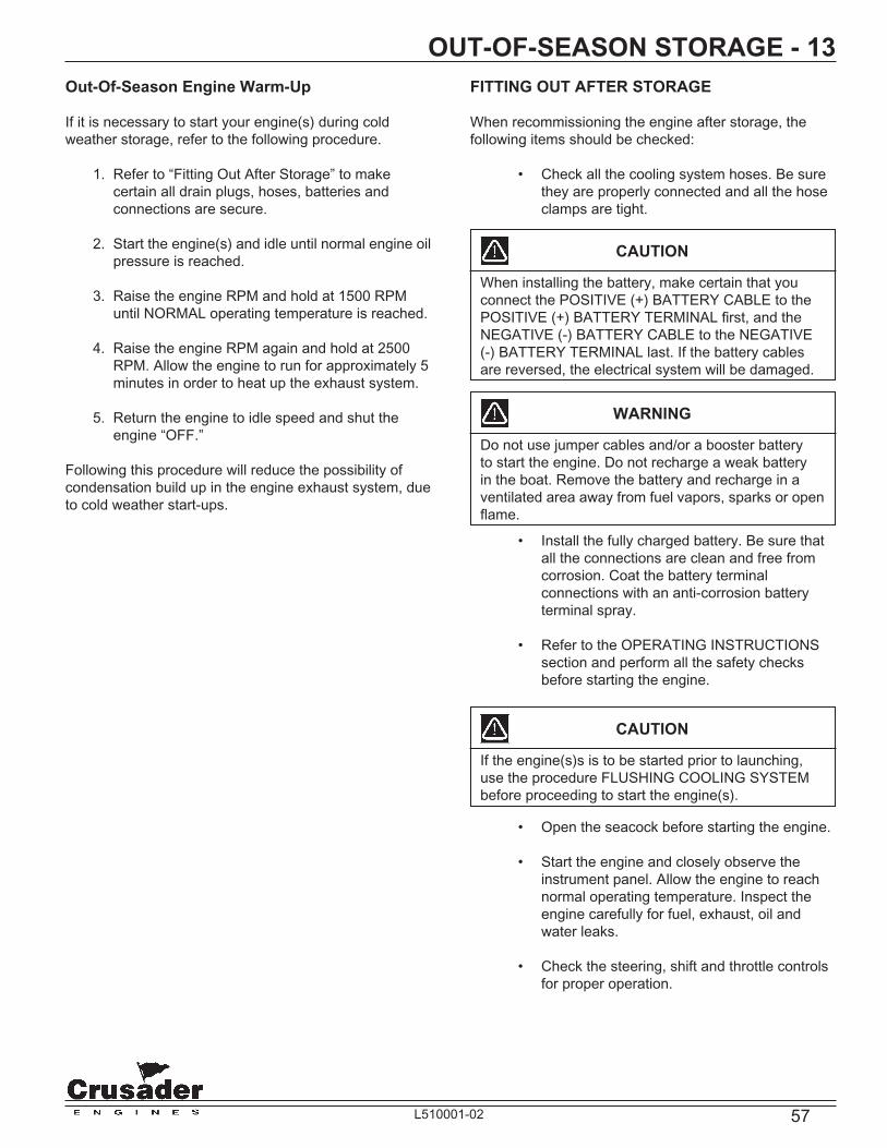
57L510001-02
OUT-OF-SEASON STORAGE - 13
CAUTION
When installing the battery, make certain that you connect the POSITIVE (+) BATTERY CABLE to the POSITIVE (+) BATTERY TERMINAL fi rst, and the NEGATIVE (-) BATTERY CABLE to the NEGATIVE (-) BATTERY TERMINAL last. If the battery cables are reversed, the electrical system will be damaged.
FITTING OUT AFTER STORAGE
When recommissioning the engine after storage, the following items should be checked:
• Check all the cooling system hoses. Be sure they are properly connected and all the hose clamps are tight.
WARNING
Do not use jumper cables and/or a booster battery to start the engine. Do not recharge a weak battery in the boat. Remove the battery and recharge in a ventilated area away from fuel vapors, sparks or open fl ame.
• Install the fully charged battery. Be sure that all the connections are clean and free from corrosion. Coat the battery terminal connections with an anti-corrosion battery terminal spray.
• Refer to the OPERATING INSTRUCTIONS section and perform all the safety checks before starting the engine.
CAUTION
If the engine(s)s is to be started prior to launching, use the procedure FLUSHING COOLING SYSTEM before proceeding to start the engine(s).
• Open the seacock before starting the engine.
• Start the engine and closely observe the instrument panel. Allow the engine to reach normal operating temperature. Inspect the engine carefully for fuel, exhaust, oil and water leaks.
• Check the steering, shift and throttle controls for proper operation.
Out-Of-Season Engine Warm-Up
If it is necessary to start your engine(s) during cold weather storage, refer to the following procedure.
1. Refer to “Fitting Out After Storage” to make certain all drain plugs, hoses, batteries and connections are secure.
2. Start the engine(s) and idle until normal engine oil pressure is reached.
3. Raise the engine RPM and hold at 1500 RPM until NORMAL operating temperature is reached.
4. Raise the engine RPM again and hold at 2500 RPM. Allow the engine to run for approximately 5 minutes in order to heat up the exhaust system.
5. Return the engine to idle speed and shut the engine “OFF.”
Following this procedure will reduce the possibility of condensation build up in the engine exhaust system, due to cold weather start-ups.

58 L510001-02
TROUBLESHOOTING - 14Engine performance complaints usuall fall under one of the basic headings listed in the Troubleshooting Guide. When a problem cannot be easily diagnosed, consult a Crusader Engines Servicing Dealer for assistance.
Malfunction Possible Cause Corrective Action
“Check Engine” light on Problem with the engine Contact Crusader Engines with the engine running management system. Dealer.
Engine will not crank with the Battery switch turned OFF (if Turn the battery switch ON. starter motor, or cranks slowly. equipped)
Remote control not in Neutral Position the remote control exactly NOTICE: Battery voltage position. in Neutral. must be AT or ABOVE 10 volts while the engine is cranking Blown the ignition fuse or open Replace the fuse - reset circuit or the engine management system circuit breakers. breakers. will not function. Loose and/or dirty wiring Check the battey cables and connections. starter circuit wiring. Clean and tighten all connections. Repair or replace the damaged wiring.
Dead Battery Recharge, test and replace as necessary.
Engine Cranks - will not Improper starting procedure. Refer to “STARTING start or is hard starting. ENGINE” in the OPERATING INSTRUCTIONS section.
NOTICE: Battery voltage No fuel - empty fuel tank Check the fuel tank level - fi ll must be AT or ABOVE 10 tank(s). Open shut-off valve(s). volts while the engine is cranking or the engine management system Plugged fuel fi lters. will not function. No fuel to the throttle body (TBI) Plugged or kinked fuel lines or or the injectors (MPI) plugged fuel-tank vent. Faulty fuel pump - check electrical connections. Faulty anti-siphon valve.
Engine fl ooded Open the throttle 100% and crank the engine. When the engine starts, immediately return the throttle to 1000 RPM.
Ignition system malfunction Contact Crusader Engines Dealer.
Contaminated fuel Check fuel for water or other contamination. If contaminated, drain and clean the fuel system.

59L510001-02
TROUBLESHOOTING - 14
Malfunction Possible Cause Corrective Action
Engine Overheats Loose or worn drive belt(s) Adjust or replace the belts as necessary.
Collapsed, kinked or leaking Replace the hoses. hoses.
Transmission/engine oil cooler Remove the water hoses and fl ush plugged in opposite direction of the normal fl ow.
Faulty thermostat Replace the thermostat. Sea-water intake valve Open the valve completely. partially/fully closed. Restricted sea-water pickup Remove restriction. Faulty temperature sending unit Test and replace as necessary. or gauge
Sea-water pump impeller worn or Replace the impeller. damaged
The following applies to engines Coolant level low in the fresh-water Check the cooling system for leaks. equipped with Fresh-Water section of the cooling system Refi ll the system. See Warning Cooling (FWC) systems. before removing the fi ll cap.
Heat exchanger passages plugged Clean and fl ush the exchanger. with scales and debris
Improper coolant mixture Install the proper coolant mixture (50% antifreeze - 50% water).
Insuffi cient engine temperature Faulty thermostat Replace the thermostat. Faulty temperature sender Replace the temperature sender.
Engine oil pressure low Faulty oil pressure sending unit Test and replace as necessary. or guage
Oil level low Add specifi ed oil. Check the engine for leaks. Crankcase overfi lled causing oil Remove the required amount of oil. aeration Determine the cause of overfi lled condition (improper fi lling, etc.). Diluted or improper grade/ Change the oil and fi lter. viscosity of oil Determine the cause of dilution. (insuffi cient engine temperature, excessive idling, etc.)

60 L510001-02
TROUBLESHOOTING - 14
Malfunction Possible Cause Corrective Action
Transmission slipping - Low oil level Add specifi ed oil. Check the erratic operation transmission for leaks.
Transmission overfi lled causing Drain required amount of oil. oil aeration
Transmission shift lever not fully Adjust the shift linkage and remote engaged control. Check the shift cables for freedom of movement and binding.
Contaminated fl uid Determine and correct the contamination source and change the fl uid. Engine misses, runs rough Ignition system malfunction Contact Crusader Engines Dealer. and/or backfi res Plugged fuel fi lters Replace the fuel fi lters. Faulty fuel pump. Have fuel pump replaced by a Crusader Engines Dealer/
Plugged or kinked fuel lines or Repair or replace the fuel lines. fuel tank vent Remove obstruction.
Anti-siphon valve faulty Clean or replace as necessary. Flame arrestor dirty Clean the fl ame arrestor.
Poor engine or boat Ignition malfunction Contact Crusader Engines Dealer. performance Throttle not fully open Check the remote control and throttle body linkage for freedom of movement and proper adjustment.
Damaged or improper propeller Repair or replace as necessary. Excessive water in the bilge Pump the water out and investigate source of entry. Excessive growth on the boat Clean the bottom and paint with an bottom anti-fouling paint. Boat overloaded Reduce and/or redistribute the load. Dirty fl ame arrestor Clean the fl ame arrestor. Engine overheating Repair the cooling system (See “Engine Overheats”).

61L510001-02
WATER FLOW DIAGRAMS - 15
Figure 15-1 Raw-Water Cooling System (5.0/5.7L)
= R
AW
WA
TE
R F
LO
W

62 L510001-02
= R
AW
WA
TE
R F
LO
W
= F
RE
SH
WA
TE
R F
LO
W
Figure 15-2 Fresh-Water Cooling System (5.05.7L)
WATER FLOW DIAGRAMS - 15

63L510001-02
Figure 15-3 Raw-Water Cooling System (8.1L)
W/ RISER
W/O RISER
Returnless Fuel System
= RAW WATER FLOW
WATER FLOW DIAGRAMS - 15

64 L510001-02
WATER FLOW DIAGRAMS - 15
Figure 15-4 Fresh-Water Cooling System (8.1L)
Re
turn
les
s F
ue
l S
ys
tem
To
En
gin
e
Blo
ck
To
En
gin
e
Blo
ck
Fro
m C
yli
nd
er
He
ad
Fro
m C
yli
nd
er
He
ad
= R
AW
WA
TE
R F
LO
W
= F
RE
SH
WA
TE
R F
LO
W

65L510001-02
WATER FLOW DIAGRAMS - 15
Figure 15-5 Thermostat Housing Waterfl ow Diagrams and Fill-Riser Waterfl ow - 8.1L Fresh-Water Cooled
HEAT
EXCHANGER
BYPASS
COOLANT FLOW
FROM
EXHAUST
MANIFOLDS
WARM-UP OPERATION
HEAT
EXCHANGER
BYPASS
FROM
EXHAUST
MANIFOLDS
NORMAL OPERATION
HEAT
EXCHANGER
BYPASS CLOSED
FROM
EXHAUST
MANIFOLDS
OVER TEMPERATURE
OPERATION

66 L510001-02
INSTRUMENTATION WIRING DIAGRAMS - 16
Figure 16-1 Typical Instrumentation Wiring Diagram
VOLTMETER
CK.
ENGINE
LT.
S
10
G
I
L
WATER
TEMP.
TACHOMETER
BRN/ORG (10)
TO ALARM BUZZER (4)
LT. BLU/TAN - 14 GA.
S
G
I
L
OIL PRESS.
BAT.
FUSE
PANEL
LTS.SOL.
IGN.
IGNITION
SWITCH GAUGE
TERMINAL
CODE
S - SENDER
G - GROUND
I - IGNITION
L - LIGHTS
CIRCUIT CIRCUIT ENGINE HARNESS INSTRUMENT PANEL
NUMBER NAME WIRE COLOR WIRE COLOR
1. GROUND BLACK BLACK
2. TACHOMETER GRAY GRAY
3. WATER TEMPERATURE TAN TAN
4. ENGINE ALARM TAN/BLACK LT. BLUE/TAN
5. IGNITION COIL PURPLE/WHITE PURPLE
6. BATTERY RED/WHITE RED/PURPLE
7. STARTER YELLOW/RED YELLOW/RED
8. OIL PRESSURE LT. BLUE LT. BLUE
9. CHECK ENGINE LIGHT BROWN/WHITE ORANGE/BROWN
10. DATA LINE ORANGE/BLACK BROWN/ORANGE
LT. B
LU
E -
14 G
A. (8
)
BL
AC
K -
10 G
A. (1
)
PU
RP
LE
- 1
4 G
A. (5
)
YE
L/R
ED
- 1
4 G
A. (7
)
RE
D/P
UR
PL
E -
10 G
A. (6
)
GR
AY
- 1
4 G
A. (2
)
TA
N -
14 G
A. (3
)
OR
N/B
RN
(
9)
DK. BLUE
14 GA.
RED/PURPLE
10 GA.
DK. BLUE
14 GA.
PURPLE
14 GA.
BLACK
10 GA.
SG
G
I
L
43
2
5
6
79
A
NOTE: ENGINE HARNESS WIRED FOR PANELS USING VOLTMETERS ONLY.
NOTE A : POWER FOR A FUSED ACCESSORY PANEL MAY BE TAKEN FROM
THIS LOCATION. LOAD CANNOT EXCEED 30 AMPS.
WIRE HARNESS COLOR CHART
8
1
10
4
3
2
ENGINE
HARNESS
5 6
7
9
81

67L510001-02
LITERATURE - 17To obtain service and/or parts literature for your Crusader Marine Engine, contact the following:
1. SERVICE: For more detailed information, Crusader has a detailed service manual available. This manual contains complete engine and component disassembly and reassembly instructions. Troubleshooting and maintenance charts are also included.
2. PARTS: Parts manuals with exploded views for service parts are available for all current engine models.
IMPORTANT: When contacting the factory fro service information, be sure to include your engine model and serial number to insure the service information you receive is correct.
Crusader EnginesPleasurecraft Engine Group
Publications Department1737 Highway 76 East
Little Mountain, SC 29075

68 L510001-02
NOTES - 18

69L510001-02
NOTES - 18