operation & maintenance manual - northern pump manuals/bulletin 150.pdf · operation &...
TRANSCRIPT

Operation & Maintenance Manual for Northern® 4900 Injection Series Pumps
Bulletin 150 REV 0.0
Operation & Maintenance Manual For Northern® 4900 Injection Series Pumps
Northern® Pump
A Division of McNally Industries, LLC
340 West Benson Avenue Grantsburg, WI 54840
Toll Free: 1-800-366-1410 Phone: 715-463-5177
Fax: 715-463-5174 www.northern-pump.com

Operation & Maintenance Manual for Northern® 4900 Injection Series Pumps
Bulletin 150 REV 0.0
Page 2 of 22
Table of Contents
Introduction........................................................................................................3 Rotation…...........................................................................................................4 Hydraulic Balance… ..........................................................................................5 Cautionary Statements......................................................................................6 Pump Installation ...............................................................................................7 Removal from Installation .................................................................................8 Disassembly.......................................................................................................9 Pump Disassembly Steps ...............................................................................10 Cleanup.............................................................................................................17 Inspection… .....................................................................................................17 Assembly..........................................................................................................19 Trouble Shooting .............................................................................................20 Lubrication and Preventative Maintenance ...................................................22 Appendix A: Exploded Pump Only Drawing Appendix B: Exploded Unit Pump Drawing
Operation & Maintenance Manual for Northern® 4900 Injection Series Pumps
Bulletin 150 REV 0.0
Seal adapter plate with NPT Connections
Seal Adapter plate with welded flange assembly
Page 3 of 22
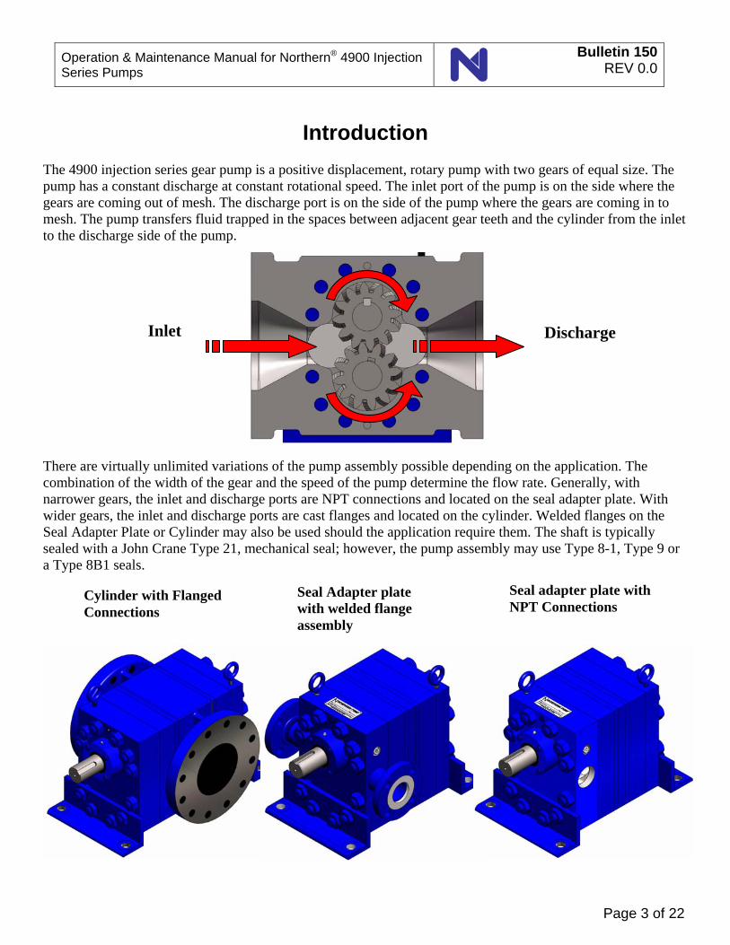
Introduction
The 4900 injection series gear pump is a positive displacement, rotary pump with two gears of equal size. The pump has a constant discharge at constant rotational speed. The inlet port of the pump is on the side where the gears are coming out of mesh. The discharge port is on the side of the pump where the gears are coming in to mesh. The pump transfers fluid trapped in the spaces between adjacent gear teeth and the cylinder from the inlet to the discharge side of the pump. There are virtually unlimited variations of the pump assembly possible depending on the application. The combination of the width of the gear and the speed of the pump determine the flow rate. Generally, with narrower gears, the inlet and discharge ports are NPT connections and located on the seal adapter plate. With wider gears, the inlet and discharge ports are cast flanges and located on the cylinder. Welded flanges on the Seal Adapter Plate or Cylinder may also be used should the application require them. The shaft is typically sealed with a John Crane Type 21, mechanical seal; however, the pump assembly may use Type 8-1, Type 9 or a Type 8B1 seals.
Inlet Discharge
Cylinder with Flanged Connections

Operation & Maintenance Manual for Northern® 4900 Injection Series Pumps
Bulletin 150 REV 0.0
Page 4 of 22
Rotation Rotation of the pump is determined by standing over the motor, and looking at the front of the pump. If the discharge of the fluid comes out of the right side of the pump, clockwise rotation is orientated. As for counter-clockwise rotation, the discharge will come out of the left side of the pump. Shown below depicts as described.
Suction-CW Rotation Discharge-CCW Rotation
Discharge-CW RotationSuction-CCW Rotation

Operation & Maintenance Manual for Northern® 4900 Injection Series Pumps
Bulletin 150 REV 0.0
Page 5 of 22
Hydraulic Balance The 4900 series are hydraulically balanced. Hydraulically balanced pumps can be identified by their through shaft design, bearing and seat housing, two mechanical seals, and roller bearing additions. Through shaft design eliminates the wear on the pump components caused by the axial thrust load generated by high inlet pressures.
Drive shaft through pump
Bearing and Seat Housing

Operation & Maintenance Manual for Northern® 4900 Injection Series Pumps
Bulletin 150 REV 0.0
Page 6 of 22
Cautionary Statements Failure to heed these cautionary statements may result in personal injury and/or damage to equipment. 1. Disable and lock-out the drive system before any work is done to install, maintain, or remove the pump. 2. Fully depressurize the entire system. 3. Close the valves closest to the pump in both the suction and discharge pipe. 4. Wear protective eyewear, and any other required face protection. 5. When handling corrosive, caustic, toxic, or hazardous liquids, wear protective clothing to prevent contact
with skin. 6. Wear protective footwear such as safety shoes. 7. When handling liquids with toxic vapors, wear a properly rated breathing mask. 8. Work area must be properly ventilated. 9. Work area must be properly grounded. 10. Do not work alone. 11. Clean up any spilled liquid immediately.

Operation & Maintenance Manual for Northern® 4900 Injection Series Pumps
Bulletin 150 REV 0.0
Page 7 of 22
Pump Installation 1. 4900 injection series pumps are heavy. Use appropriate lifting and transportation methods and means (hoist, forklift, pallet jack, etc) when moving a pump. 2. Turn off and lock out the drive mechanism. 3. Fully depressurize both the suction and discharge lines to the pump. 4. Close the valve in the suction and discharge lines closest to the pump. 5. Place a pan or other liquid collecting device under the pump to collect the liquid that may drain from the pump and the suction and discharge lines when connected to the pump. 6. Level and properly align pump. 7. Line pipes up naturally. Forcing pipes into place with flange bolts can draw pump out of alignment. Support pipes independently to eliminate strain on pump casing. Check alignment again and correct if necessary. 8. Test inlet pipe lines with pressure for leaks to ensure that they are completely airtight. The inlet piping must have a diameter equal to, or larger than, the pump inlet port. 9. Test rotation of the motor to ensure that the pump rotates in the direction indicated by arrow on pump casing. 10. Do not subject pumps to thermal shock by exposing a cold pump to a hot liquid supply or vice versa.

Operation & Maintenance Manual for Northern® 4900 Injection Series Pumps
Bulletin 150 REV 0.0
Page 8 of 22
Removal from Installation 1. Turn off and lock out the drive mechanism. 2. Fully depressurize both the suction and discharge lines to the pump. 3. Close the valve in the suction and discharge lines closest to the pump. 4. Place a pan or other liquid collecting device under the pump to collect the liquid that may drain from the
pump or the suction and base plate when assembly is disconnected. 5. Remove the coupling hub and key from the drive shaft. Clean any residue from the drive shaft. Remove
any burrs or upset metal from the surface of the drive shaft.

Operation & Maintenance Manual for Northern® 4900 Injection Series Pumps
Bulletin 150 REV 0.0
Page 9 of 22
Disassembly The pump body is a series of plates held together with ten studs (6x 22, 4x 23) and two dowels (26). The dowels provide the alignment of the pump body and are precision parts. The faying surfaces of the plates are ground flat and sealed with an O-ring. Be prepared to use some force to take the pump apart. However, you are also trying to reuse as much of the pump as possible, so be careful not to damage parts unnecessarily. Before disassembly, mark the pump housing so that you will know how the parts were arranged before the pump was taken apart. A scribe line or permanent marker line along one edge and a diagonal from corner to corner works quite well.
Suggested marker or scribed lines across plates.

Bulletin 150REV 0.0
Operation & Maintenance Manual for Northern® 4900 Series Injection Pumps
Pump Disassembly Steps
Remove the Mounting Brackets (2x 25) and the Outer Jam Nuts (8x 29)that secure the Mounting Brackets.
Page 10 of 22
Loosen and remove the Cap Screws (4x 20) and Lock Washers (4x 19) that retain the Bearing & Seat Housing (15).
Step
Step
Bulletin 150REV 0.0
Operation & Maintenance Manual for Northern® 4900 Series Injection Pumps
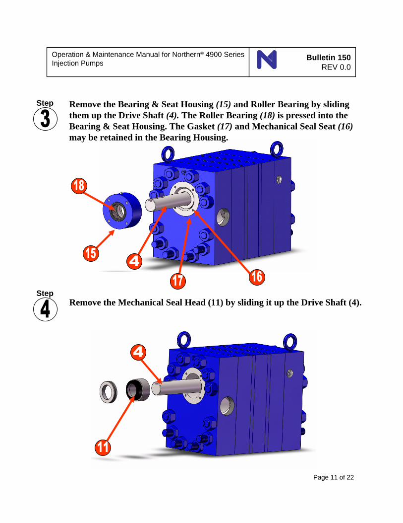
Remove the Bearing & Seat Housing (15) and Roller Bearing by sliding them up the Drive Shaft (4). The Roller Bearing (18) is pressed into the Bearing & Seat Housing. The Gasket (17) and Mechanical Seal Seat (16)may be retained in the Bearing Housing.
Remove the Mechanical Seal Head (11) by sliding it up the Drive Shaft (4).
Page 11 of 22
Step
Step

Bulletin 150REV 0.0
Operation & Maintenance Manual for Northern® 4900 Series Injection Pumps
Loosen and remove the Whole Nuts (6x 24) and Jam Nuts (4x 28) that retain the Seal Adapter Plate. Remove the Seal Adapter Plate (13) by sliding it up the Drive Shaft (4), Studs (6x 22 & 4x 23), and Dowels (2x 26).
Step
Step
Page 12 of 22
Remove the Front Bearing plate (10). The Bearing Washers (4x 9) and Roller Bearings (2x 8) will remain installed in the Bearing Plate. The Rollers may fall out of the out of the Bearing Plate. This is normal.

Bulletin 150REV 0.0
Operation & Maintenance Manual for Northern® 4900 Series Injection Pumps
Remove the Front Liner Plate (7) from the assembly by sliding it up the Drive Shaft and Studs. Note the orientation.
Step
Step
Page 13 of 22
Remove the Driven shaft (4) and Drive shaft (3). The shaft and gear are pressed together as one assembly.

Bulletin 150REV 0.0
Operation & Maintenance Manual for Northern® 4900 Series Injection Pumps
Remove the Cylinder (1) from the assembly.
Remove the Rear Mechanical Seal by removing the Cap Screws (4x 20), Lock Washers (4x 19), and the Bearing & Seat Housing (15).
Page 14 of 22
Step
Step

Bulletin 150REV 0.0
Operation & Maintenance Manual for Northern® 4900 Series Injection Pumps
StepRemove the Mechanical Seal Head (11) by sliding it down the Drive Shaft (4). At this point, the Drive Shaft and Gear, Studs, and Dowels may be removed.
Page 15 of 22
Remove the Rear Liner Plate (7). Step

Bulletin 150REV 0.0
Operation & Maintenance Manual for Northern® 4900 Series Injection Pumps
Remove the rear Bearing plate (10). The Bearing Washers (9) and Roller Bearing (8) will remain installed in the Bearing plate. The Rollers may fall out of the out of the Bearing plate. This is normal. Remove the Studs and Dowels if you have not already. Disassembly is complete.
Step
Page 16 of 22

Operation & Maintenance Manual for Northern® 4900 Injection Series Pumps
Bulletin 150 REV 0.0
Page 17 of 22
Clean-up 1. Clean all parts of the pump in accordance with your specified cleaning procedures. Take all appropriate
precautions to prevent damage to the parts of the pump during the cleaning process. 2. All pump parts should accept a wide variety of acceptable cleaning methods or chemicals. 3. All parts of the pump may be heated to 320ºF (160 ºC). 4. Clean the flat surfaces of the pump body parts by rubbing them lightly on a fine sand paper (240-320
grit) stretched or laid on a flat ground surface. Move the part in either a circular or figure eight pattern so that fine scratches are not produced across the part. Wetting the sand paper with solvent will improve the ability of the sandpaper to clean the parts.
Inspection
1. Visually inspect all parts for obvious problems- scratches on surfaces that mate with seals, cracks, upset
metal that will affect how parts mate together, burrs, or other serious wear. Correct problem or replace part as necessary.
2. Inspect the shaft and bearing plates for excessive grooves or other signs of severe wear in bearing bores
and gear wear surfaces. 2.1 The bearing bores must be free of major scratches and major scoring. 2.2 The lubrication groove must be clean. 3. Inspect the drive shaft and gear for wear: 3.1 No burrs or upset material is allowed on the surface of the drive shaft that mates with the coupling. 3.2 Visually inspect the end surfaces of the gear. Major nicks, scratches, grooves, or other defects could
be a sign of imminent gear failure. 3.3 Visually inspect the Outside Diameter of the gear. No major nicks, scratches, grooves, or other
defects are allowed. 3.4 Visually inspect the gear teeth. The surfaces of the gear teeth must be smooth and free of obvious
wear or damage. 4. Inspect the driven shaft and gear for wear: 4.1 No burrs or upset material is allowed on the surface of the drive shaft that mates with the coupling. 4.2 Visually inspect the end surfaces of the gear. Major nicks, scratches, grooves, or other defects could
be a sign of imminent gear failure.
Operation & Maintenance Manual for Northern® 4900 Injection Series Pumps
Bulletin 150 REV 0.0
Page 18 of 22
4.3 Visually inspect the Outside Diameter of the gear. No major nicks, scratches, grooves, or other
defects are allowed. 4.4 Visually inspect the gear teeth. The surfaces of the gear teeth must be smooth and free of obvious
wear or damage. 5. Inspect the cylinder for wear: 5.1 Visually inspect the end surfaces of the cylinder. No nicks, burrs, or scratches are allowed on the
ends of the cylinder. 5.2 Visually inspect the gear bores for any sign that the gear has contacted the surface of the gear bore.
No major nicks, scratches, grooves, or galling is allowed on the gear bore surface. If any of these conditions exist, check the gear outer diameter, shaft bearing diameter, and bearing bore diameter for wear and replace as necessary.
6. Inspect the seal adapter plate: 6.1 Visually inspect the seal adapter plate for nicks, scratches, or burrs on the mating surfaces. No nicks,
scratches, or burrs that will affect the mate-up of the parts at assembly or that will affect the ability of the O-ring to properly seal are allowed.
7. Inspect the Bearing & Seat housing: 7.1 Inspect the bearing and bore. No scoring or other abnormal wear patterns are allowed. If necessary,
the bearing may be pressed out of the Bearing housing and replaced by pressing in a new one. 8. Inspect the O-rings: 8.1 Visually inspect the O-rings. No nicks, scratches, cuts, tears, or permanent deformation are allowed. 8.2 Inspect the O-rings for aging. The O-rings must be firm and pliable. Replacement of O-rings is
recommended whenever the pump is disassembled.

Operation & Maintenance Manual for Northern® 4900 Injection Series Pumps
Bulletin 150 REV 0.0
Page 19 of 22
Assembly
1. Visually inspect all parts for obvious problems- scratches on surfaces that mate with seals, cracks, upset
metal that will affect how parts mate together, burrs, or other serious wear. Correct problem or replace part as necessary.
2. Complete disassembly procedures in reverse order. 3. Use a light coat of a stable, pure, synthetic oil on the shafts, gear, and studs to facilitate assembly. 3. Avoid touching the polished faying surfaces of the Mechanical Seal Head (11) and Seat (16). 4. Torque the Whole nuts (24) and Jam nuts (28) to not more than 310 foot-pounds. 5. Drive shaft & gear should turn freely after completion of assembly.

Operation & Maintenance Manual for Northern® 4900 Injection Series Pumps
Bulletin 150 REV 0.0
Page 20 of 22
Trouble Shooting Guide
(Standard for all 4000 series pumps)
Problem Solution Key will not fit into keyway in drive shaft
Check for burrs and nicks in the keyway and on the key. Remove as required. Measure width of key and keyway, if an interference fit is found, reduce the width of the key.
Motor shaft turns but pump shaft does not Verify that the coupling has been properly
installed with the correct key in each hub. Verify that the set screws are properly tightened in each coupling hub.
Pump will not prime
Check for air leaks in the suction line. Check for correct rotation of the pump shaft -- CW when facing the shaft end of the pump. “Wet” the internals of the pump with the liquid to be pumped to provide a liquid hydraulic seal in the pumping chamber. Make sure that all suction and discharge line valves are open. Make sure that the suction and discharge lines are free of obstructions.

Operation & Maintenance Manual for Northern® 4900 Injection Series Pumps
Bulletin 150 REV 0.0
Page 21 of 22
Problem Solution
Pump requires too much torque
Make sure that the viscosity of the liquid being pumped is not abnormally high. Check alignment of pump.
Pumped liquid has entrained air
Check for air leaks in suction line.
Flow rate is too low
Make sure that the viscosity of the liquid being pumped is not abnormally low. Make sure that the discharge pressure is not abnormally high. Make sure that there are no air leaks in the suction line. Verify that the rotational speed is correct. Disassemble pump and verify that the internal clearances are within specification.

Operation & Maintenance Manual for Northern® 4900 Injection Series Pumps
Bulletin 150 REV 0.0
Page 22 of 22
Lubrication and Preventative Maintenance The pump is fully lubricated by the pumped liquid. Dry running must be avoided, as it will cause internal damage to the pump. It is recommended that a very small amount of a liquid compatible with the liquid to be pumped be put into the pump at startup. This will lubricate the pump during the startup period and make the pump much easier to prime. There is no preventative maintenance routine to follow for this pump as there are no manual adjustments or other actions required for normal operation. Grease seal housing bearing on pumps with general purpose bearing grease every 6 months or every 500 hours of operation, whichever occurs first (see image below).
Grease Fitting

28
8a
22
20
7
47
24
8c
5
1520
1
8b2
10
11
13
10
1524
26
25
13
3
8a
23
Appendix ANumber Part Name Qty.
1 Cylinder 12 Driven Gear 13 Drive Gear 14 Drive Shaft 15 Driven Shaft 16 Name Plate 17 Liner Plate 2
8a Bearing Sleeve 48b Bearing Washer 48c Bearing Roller 9210 Bearing Plate 211 Mechanical Seal Head 112 Retaining Ring 113 Seal Adapter Plate 114 End Plate 115 Bearing & Seat Housing 116 Mechanical Seal Seat 117 Gasket 118 Roller Bearing 119 Lock Washer 420 Capscrew 421 Grease Zerk 122 Stud Short 423 Stud-Long 624 Whole nut 1225 Mounting Bracket 226 Dowel Pin 227 Eyebolt 228 Jam Nut 16

3
5
2
1
6
4
10
8
7
9
Appendix B
No. Part Name Qty.1 Hex Head Cap Screw 42 Hex Head Cap Screw 43 Hex Head Cap Screw 44 WEG Motor 15 Pump Assembly 16 Coupling Guard 17 Coupling Cover 18 Coupling Insert 19 Coupling Hub 110 Coupling Hub 1

13
17
11
16
15
20
1918
SEAL ACCESSPIPE PLUG
3 FLATSEQUALLY SPACED
4
John Crane Type 8-1Mechanical Seal
Configuration
The Mechanical Seal Head (11) is retained on the Drive Shaft (4) by three set screws. The set screws are secured against the drive shaft in the three flats on the Drive Shaft. The set screws are accessed through the hole in the Seal Adapter Plate (13) which is sealed with the Pipe Plug.