operation maintenance manual gear-driven centrifugal water
TRANSCRIPT

Operation Maintenance Manual
Gear-Driven CentrifugalWater-Cooled LiquidChillers with CH530Controls
CVGF-SVU02B-E4X39640691020
Unit ModelCVGF 400-1000 Ton Units(50 and 60 Hz)
CVGF-SVU02B-E4© 2005 American Standard Inc. All rights reserved.
Warnings andCautions
Warnings and CautionsNotice that warnings andcautions appear at appropriateintervals throughout thismanual. Warnings are providedto alert installing contractors topotential hazards that couldresult in personal injury ordeath, while cautions are
designed to alert personnel toconditions that could result inequipment damage.
Your personal safety and theproper operation of this machinedepend upon the strictobservance of these precautions.
NOTICE: Warnings and Cautions appear at appropriate sections throughout this manual. Read these carefully.
��WARNING – Indicates a potentially hazardous situation which, if not avoided, could resultin death or serious injury.
��CAUTION – Indicates a potentially hazardous situation which, if not avoided, may result inminor or moderate injury. It may also be used to alert against unsafe practices.
CAUTION – Indicates a situation that may result in equipment or property-damage-onlyaccidents.

CVGF-SVU02B-E4 3
Contents
Warnings and Cautions
General Information
Unit Control Panel (UCP)
Base Loading Control Algorithm
Control System Components
Machine Protection and Adaptive
Unit Startup
Unit Shutdown
Periodic Maintenance
2
4
22
44
47
62
73
76
77

CVGF-SVU02B-E44
Model Number
Refer to the Installation Manual.
Product Description BlockA typical Product DescriptionBlock is shown in the InstallationManual.
Unit Nameplate
The unit nameplate is located onthe left side of the unit controlpanel.
Note: Trane starters areidentified by a separate modelnumber found on the starter.
Literature History
CVGF-SVU02A-E4 (November 2002)
This is a new manual.
About this manual
Operation and maintenanceinformation for models CVGFare covered in this manual. Thisincludes both 50 and 60 Hz.CVGF centrifugal chillersequipped with the Tracer CH530Chiller Controller system.
Carefully review this informationand follow the instructions givento successfully operate andmaintain a CVGF unit.
If mechanical problems dooccur, contact a qualified serviceorganization to ensure properdiagnosis and repair of the unit.
GeneralInformation

CVGF-SVU02B-E4 5
Commonly UsedAbbreviations
For convenience, a number ofabbreviations are usedthroughout this manual. Theseare listed alphabetically below,along with a translation of each:
ASME = American Society ofMechanical Engineers
ASHRAE = American Society ofHeating, Refrigerating and AirConditioning Engineers
BAS = Building AutomationSystem
CDBS = Condenser Bundle Size
CDSZ = Condenser Shell Size
CH530 = Tracer CH530 Controller.
CWR = Chilled Water Reset
CWR’ = Chilled Water ResetPrime
DTFL = Design Delta-T at FullLoad (for example, thedifference between entering andleaving chilled watertemperatures)
DV = DynaView™ Clear LanguageDisplay, also know as the MainProcessor (MP)
ELWT = Evaporator LeavingWater Temperature
ENT = Entering Chilled WaterTemperature
EXOP = Extended Operation
GBAS = Generic BuildingAutomation Interface
GPM = Gallons-per-minute
HLUV = High Lift UnloadingValve.
Hp = Horsepower
HVAC = Heating, Ventilating, andAir Conditioning
IE = Internally-Enhanced Tubes
IPC = InterprocessorCommunication
LCD = Liquid Crystal Display
LED = Light Emitting Diode
GeneralInformation
LLID = Low Level IntelligentDevice (Sensor, PressureTransducer, or Input/output UCPmodule)
MAR = Machine Shutdown AutoRestart (Non-Latching wherechiller will restart whencondition corrects itself.)
MMR = Machine ShutdownManual Restart (Latching wherechiller must be manually reset.)
MP = Main Processor
PFCC = Power Factor CorrectionCapacitor
PID = Proportional IntegralDerivative
PSID = Pounds-per-Square-Inch(differential pressure)
PSIG = Pounds-per-Square-Inch(gauge pressure)
ODT = Outdoor Temperature
OPST = Operating StatusControl
RLA = Rated Load Amps
RTD = Resistive TemperatureDevice Tracer CH530= ControlsPlatform used on this Chiller
TRMM = TracerCommunications
UCP = Unit Control Panel
CVGF-SVU02B-E46
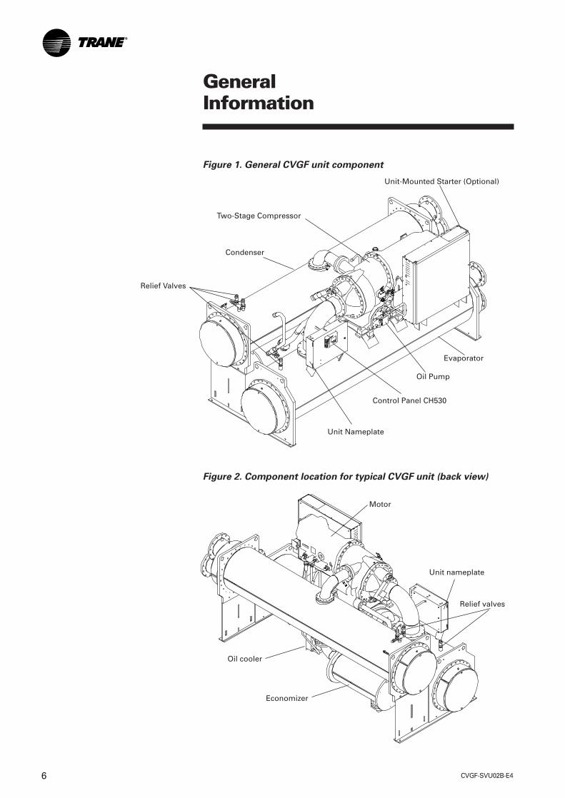
Figure 2. Component location for typical CVGF unit (back view)
Motor
Unit nameplate
Relief valves
Oil cooler
Economizer
Condenser
Two-Stage Compressor
Unit-Mounted Starter (Optional)
Relief Valves
Unit Nameplate
Control Panel CH530
Oil Pump
Evaporator
GeneralInformation
Figure 1. General CVGF unit component

CVGF-SVU02B-E4 7
Cooling Cycle
The refrigeration cycle of theCVGF chiller can be describedusing the pressure-enthalpydiagram shown in Figure 3. Keystate points are indicated andwill be referred to in thefollowing discussion. Aschematic of the systemshowing refrigerant flow is givenin Figure 4.
Evaporator - A liquid vaporrefrigerant mixture enters theevaporator at state point 1.Liquid refrigerant is vaporized tostate point 2 as it absorbs heatfrom the system cooling load.The vaporized refrigerant flowsinto the compressor first stage.
Compressor first stage -Refrigerant vapor is drawn fromthe evaporator into the firststage compressor. The first stageimpeller accelerates the vaporincreasing its temperature andpressure to state point 3.
GeneralInformation
Figure 3. P-H chart
P
Pc
P1
Pe
5
8
1
RE
RE1
Evaporator
Economizer
Condenser4Compressor2nd stage
3Compressor1st stage
2
H

CVGF-SVU02B-E48
Compressor second stage -Refrigerant vapor leaving thefirst stage compressor is mixedwith cooler refrigerant vaporfrom the economizer. Thismixing lowers the enthalpy ofthe vapor entering the secondstage. The second stageimpeller accelerates the vapor,further increasing itstemperature and pressure tostate point 4.
Condenser - Refrigerant vaporenters the condenser where thesystem cooling load and heat ofcompression are rejected to thecondenser water circuit. Thisheat rejection cools andcondenses the refrigerant vaporto a liquid at state point 5.
Economizer and refrigerantorifice system - Liquidrefrigerant leaving thecondenser at state point 5 flowsthrough the first orifice andenters the economizer to flash asmall amount of refrigerant atan intermediate pressurelabeled P1. Flashing some liquidrefrigerant cools the remainingliquid to state point 8.
Another benefit of flashingrefrigerant is to increase thetotal evaporator RefrigerationEffect from RE’ to RE. Theeconomizer provides around 4percent energy savingscompared to chillers with noeconomizer.
To complete the operating cycle,liquid refrigerant leaving theeconomizer at state point 8flows through a second orifice.Here refrigerant pressure andtemperature are reduced toevaporator conditions at statepoint 1.
An innovative design feature ofthe CVGF chiller is maximizingthe evaporator heat transferperformance while minimizingrefrigerant charge requirements.This is accomplished by theTrane-patented falling filmevaporator design. The amountof refrigerant charge required inCVGF is less than that incomparably sized chillers offlooded evaporator design.
GeneralInformation

CVGF-SVU02B-E4 9
GeneralInformation
Figure 4. Refrigerant flow diagram
Starter
Condenser
Motor
Economizer Oil sump
Pump
Fixedorifice
Distributor
Evaporator
Fixedorifice
Strainer
Fixedorifice
Condensersump
Internal filter
Compressor
InletvanesHigh lift
unloadingvalve(HLUV)
Gears
Bearings
Oil cooler
Refrigerant Flow
S
F
ST2
ST1
CVGF-SVU02B-E410
Compressor Description
The CVGF compressor consistsof three distinct sections: thetwo-stage centrifugalcompressor, the motor, and thegear box with integral oil sump.See Figure 5.
CompressorThe centrifugal compressor istwo-stage with high-strengthaluminum alloy fully shroudedimpellers. The impellers aretested at 25 percent over designoperating speed. The rotatingassembly is dynamicallybalanced for vibration of lessthan 5.1 mm/sec (0.2 ips peakvelocities) at nominal operatingspeeds. The control systemaffords 20 to 100 percentcapacity modulation byelectrically actuated guide vanesupstream of each impeller.
GeneralInformation

CVGF-SVU02B-E4 11
GeneralInformation
Figure 5. Compressor cross-section view
Motor rotor
Motor shaft
Bull gearDischarge end
Suctionend
Motor terminalMotorhousing
Motor stator
Pinion shaft
Gear housing
2nd stageimpeller
Oil pump
1st stageimpeller
Oilsump
CVGF-SVU02B-E412
Drive TrainThe drive train consists ofhelical bull and pinion gears.Gear tooth surfaces are casehardened and precision ground.The one-piece impeller shaft issupported by hydrodynamicthrust and radial bearings.
MotorThe motor is a hermetic, liquidrefrigerant cooled, two-pole,low-slip squirrel cage inductionmotor. A radial hydrodynamicbearing and duplex angularcontact ball bearings supportthe rotor assembly. Winding-embedded sensors providepositive thermal protection.
Controls Overview
Controls Operator InterfaceInformation is tailored tooperators, service techniciansand owners. When operating achiller, there is specificinformation you need on a day-to-day basis such as setpoints,limits, diagnostic information,and reports.
When servicing a chiller, youneed different information and alot more of it such as historicand active diagnostics,configuration settings, andcustomizable controlalgorithms, as well as operationsettings.
By providing two different tools,one for daily operation and onefor periodic service, appropriateinformation is readilyaccessible.
DynaView™ Human InterfaceFor the operator, day-to-dayoperational information ispresented at the panel. Up toseven lines of data (English or SIunits) are simultaneouslydisplayed on the touch-sensitivescreen. Logically organizedgroups of information such aschiller modes of operation,active diagnostics, settings andreports put informationconveniently at your fingertips.See Operator Interface Sectionfor details.
TechView™ ChillerFor the service technician oradvanced operator all chillerstatus, machine configurationsettings, customizable limits,and up to 60 active or historicdiagnostics are displayedthrough the TechView™
interface. Using TechView™, atechnician can interact with anindividual device or a group ofdevices for advancedtroubleshooting. LED lights andtheir respective TechView™
indicators visually confirm theviability of each device. Any PCthat meets the systemrequirements may download theservice interface software andTracer CH530 updates. For moreinformation on TechView™ visityour local Trane Servicecompany, or The TraneCompany’s website atwww.trane.com.
GeneralInformation
CVGF-SVU02B-E4 13
GeneralInformation
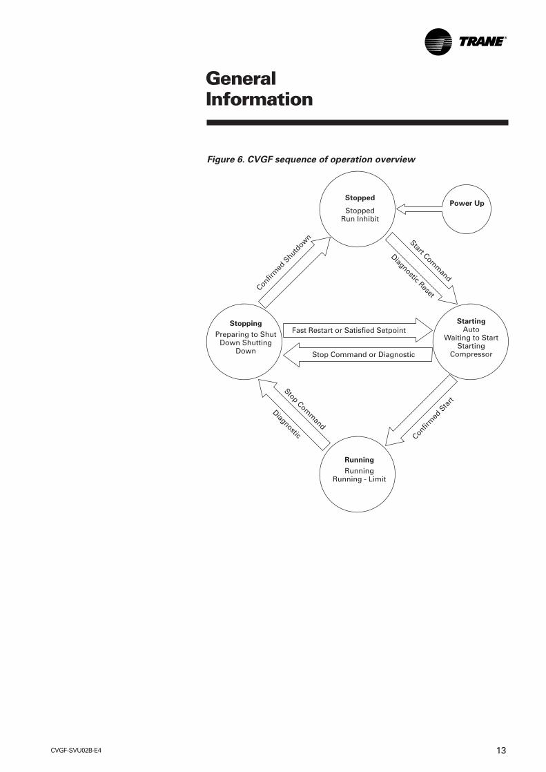
Figure 6. CVGF sequence of operation overview
Stopped
StoppedRun Inhibit
Power Up
Stopping
Preparing to ShutDown Shutting
Down
StartingAuto
Waiting to StartStarting
Compressor
Running
RunningRunning - Limit
Fast Restart or Satisfied Setpoint
Stop Command or Diagnostic
Confirm
ed S
hutdow
n
Confirm
ed S
tart
Stop Comm
and
Diagnostic
Start Comm
and
Diagnostic Reset

CVGF-SVU02B-E414
GeneralInformation
Figure 7. Sequence of operation: power up
ApplyControlPower
Completing Self Test (12 Seconds)
Self
Test
Starting Application(20-30 Seconds*)
Sta
rtin
gA
pp
licati
on
*Note: The variation in DynaView Power Up time is dependent on the number ofinstalled options.
Last ModeSuch asAuto orStoppedas shown
CVGF-SVU02B-E4 15
GeneralInformation
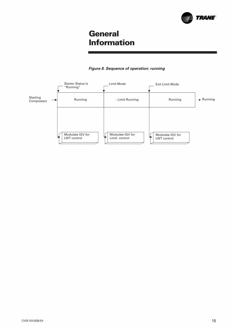
Figure 8. Sequence of operation: running
Starter Status is“Running”
Limit Mode Exit Limit Mode
StartingCompressor Running - Limit Running Running
Modulate IGV forLWT control
Running
Modulate IGV forLimit control
Modulate IGV forLWT control

CVGF-SVU02B-E416
Figure 9. Immediate shutdown to stopped or run inhibit
GeneralInformation
Running
Immediate shutdown non-latching diagnostic
Immediate shutdown latching diagnostic
Panic stop
Run Inhibit
Stopped
Post lube complete
Run Inhibit orStopped
Post lube and evaporatorpump off delay complete
Shutting down Shutting down Shutting down
Close IGV(0-50 seconds)
Post Lube:(1 minute)
De-energize oil pump
Confirm no oil pressure*5 minutes after oil pump is de-energized
De-energize evaporatorwater pump relayEvaporator pump off
delay not performed forimmediate shutdown
De-energizecompressor
Confirm no compressor currents 8seconds after compressor is de-energized
De-energize condenserwater pump
*Note: No oil pressure when oil differential pressure switch is open.
CVGF-SVU02B-E4 17
GeneralInformation
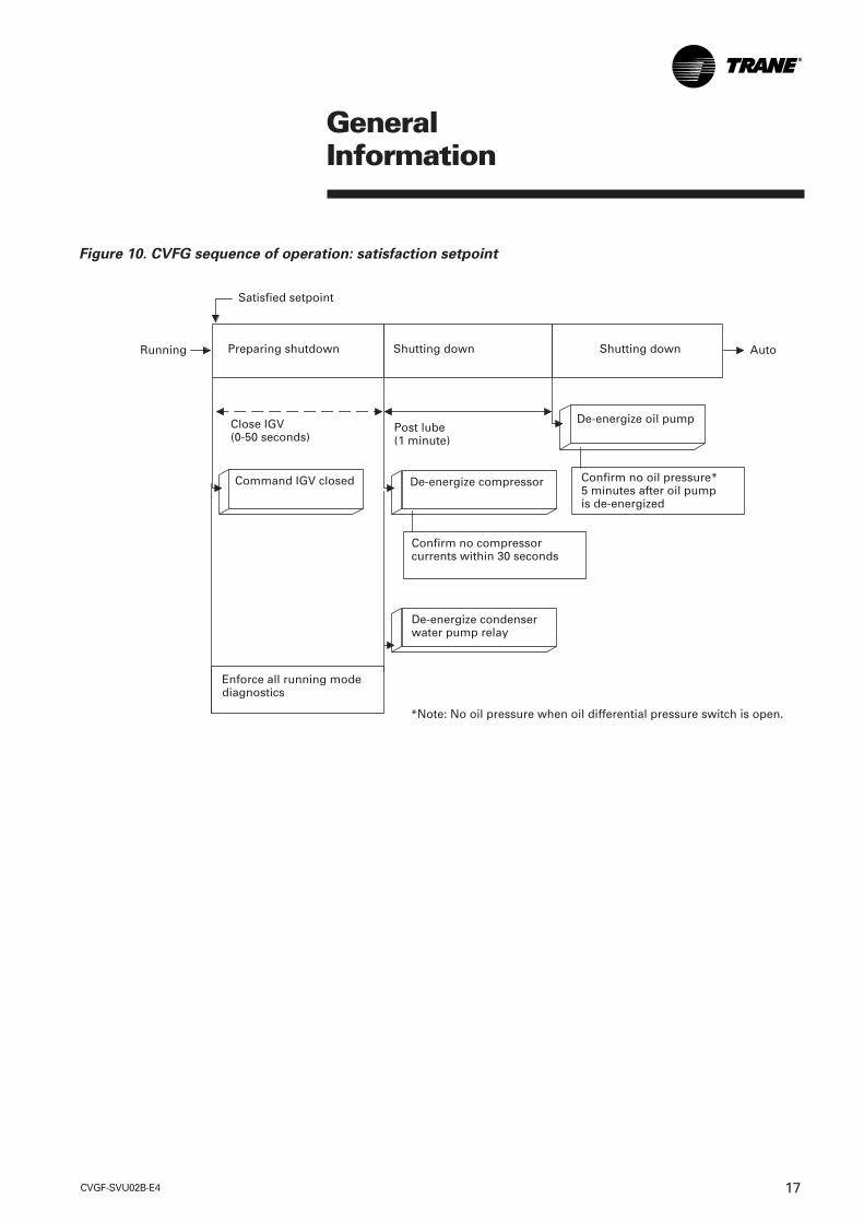
Figure 10. CVFG sequence of operation: satisfaction setpoint
Running Preparing shutdown Shutting down Shutting down
*Note: No oil pressure when oil differential pressure switch is open.
Satisfied setpoint
Command IGV closed De-energize compressor Confirm no oil pressure*5 minutes after oil pumpis de-energized
De-energize oil pumpClose IGV(0-50 seconds)
Post lube(1 minute)
Auto
Confirm no compressorcurrents within 30 seconds
De-energize condenserwater pump relay
Enforce all running modediagnostics

CVGF-SVU02B-E418
Oil Management
The primary purpose of OilManagement is to ensureappropriate and sufficientlubrication to the bearingsduring compressor operationand to minimize refrigerantdilution in the oil.
The Oil Management systemperforms safety checks andmanages the operation of the OilPump and the Oil Heater. Thesensor inputs used for thesepurposes are the Differential OilSwitch, and the Oil Temperature.
Two oil heater outputs exist, thatshould always operatesimultaneously, for example,both on or both off.
Note: The Oil Pump and the OilHeater are never energized at thesame time.
Low Oil Temperature StartInhibit Setpoint default is: 95° F.
When enhanced oil protection isenabled, the low oil temperaturestart inhibit is the saturatedevaporator at 30°F (16.6°C) or105°F (40.5°C), whichever ishigher.
When enhanced oil temperatureprotection is enabled, the oiltemperature setpoint is fixed at136°F (57.8°C).
The oil temperature controlsetpoint range is settable from:100 to 160°F (37.8 to 71.1°C)
Essential Modes
The Oil-Management has thefollowing modes:
1. Low Temperature Start Inhibit:
The oil temperature is at orbelow the low oil temperaturestart inhibit setpoint. The heateris energized to raise the oiltemperature. See LowTemperature Start Inhibit sectionfor information about EnhancedOil Temp Protection.
This mode is indicated to theuser.
2. Idle: The oil pump is off. Theoil temperature is maintainedby the heater, at the control-temperature setpoint +/- 2.5°F(1.4°C).
3. Pre-lube: The oil pumplubricates the bearing for 30seconds before thecompressor starts.
This mode is indicated to theuser.
4. Running: The oil pumpcontinues to lubricate thebearings when the compressoris running.
GeneralInformation

CVGF-SVU02B-E4 19
5. Post-lube: The oil pumplubricates the bearings for 60seconds after the compressoris stopped to ensure bearingsremain lubricated as thecompressor coasts to a stop.
If a start command is issuedwhile in post-lube, a quick restartwill be performed.
The post-lube mode is indicatedto the user on DynaView™ andTechView™.
6. Manual: The oil pump can becommanded on and off in amanual mode.
Oil Temperature ControlThe oil heater is used tomaintain the oil temperaturewithin +/- 2.5°F (4.5°C) of the oiltemperature control setpoint.The oil heater is commanded offwhen the oil pump iscommanded on.
Oil Differential PressureCheck
The Oil Differential PressureCheck validates the oildifferential pressure before theoil pump is turned on. This checkin necessary in case thedifferential pressure switch isnot operational. Without thischeck, the differential oilpressure feedback is gone. Thischeck is made after post-lube iscomplete to verify that thedifferential pressure hasdropped to indicate no oil flow.
Here are the details:
• CH530 verifies that thepressure switch is reading nodifferential pressure with theoil pump off before proceedingwith pre-lube.
• CH530 displays a modeWaiting for Low Oil DifferentialPress.
• The check is made if oil pumpis off and before it is turned on.
• CH530 allows five minutes forthe differential oil pressureswitch to open.
• This check is performed onpower up or reset also. If aMPL occurred or power up waswithin the post-lube time, oilpump is running so do not dothe check.
GeneralInformation

CVGF-SVU02B-E420
Protective Diagnostics andtheir description
Differential Oil Pressure Overdueis a latching diagnostic that cancome up while the unit is in pre-lube.
The differential pressure switchstatus is used instead of the LowDifferential Oil Pressure Cutoutsetpoint.
Low Differential Pressure Cutoutis a latching diagnostic that cancome up while the unit isrunning. Oil pressure isindicative of oil flow and activeoil pump operation. Significantfall in oil pressure is indicative offailure of the oil pump, oilleakage, or other blockage in theoil circuit.
Once oil flow has beenestablished, if the differentialpressure switch indicates thereis not oil pressure for 2 seconds,this diagnostic will be issued.
Unexpected Differential OilPressure is a latching diagnosticthat can come up while the unitis idle and is implemented torecognize and ensure that thepressure switch is operationaland that it is open for a period offive minutes.
GeneralInformation

CVGF-SVU02B-E4 21
GeneralInformation
Figure 11. Oil circuit diagram
Starter
Condenser
Economizer
CondenserSump
High LiftUnloading
Valve (HLUV)
Refrigerant
Oil
Motor
Oil Cooler
StrainerS
F
Distributor
Evaporator
Fixed Orifice
Oil SumpPump
Internal Filter
Bearings
GearsST 1ST 2
Compressor
Fixed Orifice
CVGF-SVU02B-E422
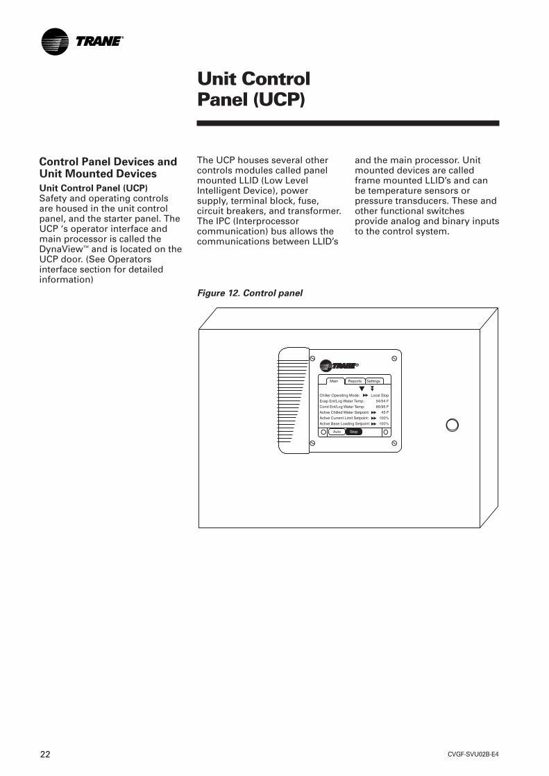
Control Panel Devices andUnit Mounted Devices
Unit Control Panel (UCP)Safety and operating controlsare housed in the unit controlpanel, and the starter panel. TheUCP ‘s operator interface andmain processor is called theDynaView™ and is located on theUCP door. (See Operatorsinterface section for detailedinformation)
The UCP houses several othercontrols modules called panelmounted LLID (Low LevelIntelligent Device), powersupply, terminal block, fuse,circuit breakers, and transformer.The IPC (Interprocessorcommunication) bus allows thecommunications between LLID’s
and the main processor. Unitmounted devices are calledframe mounted LLID’s and canbe temperature sensors orpressure transducers. These andother functional switchesprovide analog and binary inputsto the control system.
Unit ControlPanel (UCP)
Figure 12. Control panel
CVGF-SVU02B-E4 23
Whenever the controller sensesa situation that might trigger aprotective shutdown, it focuseson bringing the criticalparameter back into control.When the parameter is no longercritical, the controller switchesits objective back to controllingthe chilled water temperature, orto another more criticalparameter should it exist.
Variable water flow through theevaporatorChilled water systems that varywater flow through chillerevaporators have caught theattention of engineers,contractors, building owners,and operators. Varying the waterflow reduces the energyconsumed by pumps, whilerequiring no extra energy for thechiller. This strategy can be asignificant source of energysavings, depending on theapplication. With its faster andmore intelligent response tochanging conditions, TracerCH530 reliably accommodatesvariable evaporator water flowand its effect on the chilled watertemperature. Theseimprovements keep chilledwater flowing at a temperaturecloser to its setpoint.
Unit ControlPanel (UCP)
Tracer CH530 ChillerController
Tracer CH530’s Main Processor,DynaView™, is fast and keepsthe chiller online wheneverpossible. Smart sensors collectthree rounds of data per second,55 times the data collectionspeed of its predecessor. Eachdevice (a sensor) has its ownmicroprocessor thatsimultaneously converts andaccurately calibrates its ownreadings from analog to digital.
Because all devices arecommunicating digitally withthe DynaView™, there is no needfor the main processor toconvert each analog signal oneat a time. This distributed logicallows the main processor tofocus on responding tochanging conditions in the load,the machine, its ancillaryequipment, or its power supply.Tracer CH530 constantlyreceives information about keydata parameters, temperaturesand currents. Every five secondsa multiple objective algorithmcompares each parameter to itsprogrammed limit. The chiller’sAdaptive Control™ capabilitiesmaintain overall systemperformance by keeping its peakefficiency.

CVGF-SVU02B-E424
DynaView™ presents three menutabs across the top which arelabeled “MAIN, REPORTS, andSETTINGS”.
The Main screen provides anoverall high level chiller statusso the operator can quicklyunderstand the mode ofoperation of the chiller.
The Chiller Operating Mode willpresent a top level indication ofthe chiller mode (Auto, Running,Inhibit, Run Inhibit, and so forth)The “additional info” icon willpresent a subscreen that lists infurther detail the subsystemmodes.
The MP contains non-volatilememory both checking for validset points and retaining them onany power loss. System datafrom modules (LLID) can beviewed at the DynaView™
operator interface. Such asevaporator and condenser watertemperatures, outdoor airtemperature, evaporator andcondenser water pump control,status and alarm relays, externalauto-stop, emergency stop, andevaporator and condenser waterflow switches.
Unit ControlPanel (UCP)
The DynaView™ (DV) OperatorInterface contains the MainProcessor (MP) whichcommunicates commands toother modules, collecting data,status and diagnosticinformation from the othermodules over the IPC (InterProcessor Communications)link. The Main Processorsoftware controls water flows bystarting pumps and sensingflow inputs, establishes a needto heat or cool, performs pre-lube, performs post-lube, startsthe compressor, performs watertemperature control, establisheslimits, and pre-positions theinlet guide-vanes.
Figure 13. DynaView™ main processor

CVGF-SVU02B-E4 25
Unit ControlPanel (UCP)
Main screen content can beviewed by selecting the up ordown arrow icons. The Mainscreen is the default screen.Afteran idle time of 30 minutes.
DynaView™ (DV) is the operatorinterface of the Tracer CH530control system utilized on theCTV machines. The DynaView™
enclosure is 9.75" (24.8 cm)wide, 8” (20.3 cm) high and 1.6”(4.1 cm) deep. The DynaView™
display is approximately 4” (10.2cm) wide by 3” (7.6) high.Features of the display include atouch screen and long life LEDbacklight. This device is capableof operating in 0 - 95 percentrelative humidity (non-condensing). The enclosureincludes a weather tightconnection means for the RS232TechView™ connection.
Touch screen key functions aredetermined completely in thesoftware and change dependingupon the subject mattercurrently being displayed. Theuser operates the touch sensitivebuttons by touching the buttonof choice. The selected button isdarkened to indicate it is theselected choice. The advantageof touch sensitive buttons is thatthe full range of possible choicesas well as the current choice isalways in view.
Up or down arrow buttons areused to allow a continuouslyvariable setpoint, such asleaving water setpoint. The valuechanges by touching the up ordown arrows.
Action buttons are buttons thatappear temporarily and providethe operator with a choice suchas Enter or Cancel. The operatorindicates his choice by touchingthe button of choice. The systemthen takes the appropriate actionand the button typicallydisappears.
DynaView™ consists of variousscreens, each meant to serve aunique purpose of the machinebeing served. Tabs are shownrow across the top of the display.The user selects a screen ofinformation by touching theappropriate tab. The folder thatis selected will be brought to thefront so it’s contents are visible

CVGF-SVU02B-E426
Unit ControlPanel (UCP)
The main body of the screen isused for description text, data,setpoints, or keys (touchsensitive areas) The double uparrows cause a page by pagescroll either up or down. Thesingle arrow causes a line byline scroll to occur. At the end ofthe screen, the appropriate scrollbuttons will disappear.
The bottom of the screen is thepersistent area. It is present in allscreens and performs thefollowing functions. The leftcircular area is used to reducethe contrast and viewing angleof the display. The right circulararea is used to increase thecontrast and viewing angle ofthe display. The contrast controlwill be limited to avoid complete“light” or complete “dark”,which would potentially confusean unfamiliar user to thinkingthe display was malfunctioning.
Persistent keys, horizontal at thebottom of the display, are thosekeys that must be available foroperation regardless of thescreen currently being displayed.These keys are critical formachine operation. The Autoand Stop keys will be presentedas radio buttons within thepersistent key display area. Theselected key will be dark. Thechiller will stop when the Stopkey is touched, entering the stopsequence. Pressing the“Immediate Stop” button willcause the chiller to stop rightaway.
The AUTO and STOP, takeprecedence over the ENTER andCANCEL keys. (While a setting isbeing changed, AUTO and STOPkeys are recognized even ifENTER or CANCEL has not beenpressed. Selecting the Auto keywill enable the chiller for activecooling.
CVGF-SVU02B-E4 27
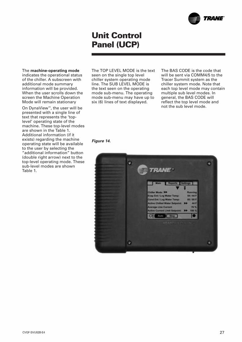
The machine-operating modeindicates the operational statusof the chiller. A subscreen withadditional mode summaryinformation will be provided.When the user scrolls down thescreen the Machine OperationMode will remain stationary
On DynaView™, the user will bepresented with a single line oftext that represents the ‘top-level’ operating state of themachine. These top-level modesare shown in the Table 1.Additional information (if itexists) regarding the machineoperating state will be availableto the user by selecting the“additional information” button(double right arrow) next to thetop-level operating mode. Thesesub-level modes are shownTable 1.
The TOP LEVEL MODE is the textseen on the single top levelchiller system operating modeline. The SUB LEVEL MODE isthe text seen on the operatingmode sub-menu. The operatingmode sub-menu may have up tosix (6) lines of text displayed.
The BAS CODE is the code thatwill be sent via COMM4/5 to theTracer Summit system as thechiller system mode. Note thateach top level mode may containmultiple sub level modes. Ingeneral, the BAS CODE willreflect the top level mode andnot the sub level mode.
Unit ControlPanel (UCP)
Figure 14.

CVGF-SVU02B-E428
Unit ControlPanel (UCP)
Table 1. A general description of the top level modes is show in the following table.Top Level Mode Description
Stopped Unit inhibited from running and will require user action to go to Auto.Run Inhibit Unit inhibited from running by Tracer, External BAS, or an Auto Reset diagnostic.Auto Unit determining if there is a need to run.Waiting To Start Unit waiting for tasks required prior to compressor start to be completed.Starting Compressor Unit is starting compressor.Running Compressor is running with no limits in effect.Running – Limit Compressor is running with limit in effect.Preparing To Shutdown Unit is closing inlet guide vanes prior to compressor shutdown.Shutting Down Compressor has been stopped and unit is performing shutdown tasks.
Figure 15.

CVGF-SVU02B-E4 29
Unit ControlPanel (UCP)
ReferenceTop Level Mode Sub Level Mode BAS Code
SYSTEM RESETNA
Stopped Local Stop 00Stopped Panic Stop 00Stopped Diagnostic Shutdown – Manual Reset 00Run Inhibit Tracer Inhibit 100Run Inhibit External Source Inhibit 100Run Inhibit Diagnostic Shutdown – Auto Reset 100Auto Waiting For Evaporator Water Flow 58Auto Waiting For A Need To Cool 58Auto Waiting For A Need To Heat 58Auto Power Up Delay Inhibit: MIN:SEC 58Waiting To Start Waiting For Condenser Water Flow 70Waiting To Start Establishing Oil Pressure 70Waiting To Start Pre-Lubrication Time: MIN:SEC 70Waiting To Start Motor Temperature Inhibit: 70
Motor Temperature / Inhibit TemperatureWaiting To Start Restart Time Inhibit: MIN:SEC 70Waiting To Start Low Oil Temperature Inhibit: 70
Oil Temperature / Inhibit TemperatureWaiting To Start Waiting For Starter To Start: MIN:SEC 70Starting Compressor There is no sub mode displayed 72Running There is no sub mode displayed 74Running Surge 74Running Base Loaded 74Running Current Control Soft Loading 74Running Capacity Control Soft Loading 74Running – Limit Current Limit 75Running – Limit Phase Unbalance Limit 75Running – Limit Condenser Pressure Limit 75Running – Limit Evaporator Temperature Limit 75Running – Limit Minimum Capacity Limit 75Running – Limit Maximum Capacity Limit 75Preparing To Shutdown Closing IGV IGV Position % 7EShutting Down Post-Lubrication Time: MIN:SEC 7EShutting Down Evaporator Pump Off Delay: MIN:SEC 7EShutting Down Condenser Pump Off Delay: MIN:SEC 7E
Boot & Application software part number, self-test, andconfiguration validity screens will be present.
CVGF-SVU02B-E430
Unit ControlPanel (UCP)
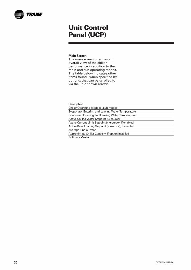
Main Screen The main screen provides anoverall view of the chillerperformance in addition to themain and sub operating modes.The table below indicates otheritems found , when specified byoptions, that can be scrolled tovia the up or down arrows.
Description
Chiller Operating Mode (>>sub modes)Evaporator Entering and Leaving Water TemperatureCondenser Entering and Leaving Water TemperatureActive Chilled Water Setpoint (>>source)Active Current Limit Setpoint (>>source), If enabledActive Base Loading Setpoint (>>source), If enabledAverage Line CurrentApproximate Chiller Capacity, If option installedSoftware Version

CVGF-SVU02B-E4 31
Unit ControlPanel (UCP)
Diagnostic ScreenThe diagnostic screen isaccessible by touching theAlarms enunciator.
When an alarm is present, thealarm enunciator is present nextto the Stop key. A flashing“alarm” indicates a machineshutdown and a non flashing“alarm” indicates aninformational message.
Machine shutdowns can be oftwo types:
Latching (MMR) requirecorrective action and manualreset.
Non-Latching (MAR) will restartautomatically when conditioncorrects itself.
Up to ten active diagnostics canbe displayed if required.
The reason for all diagnosticsmust be determined andcorrected. Do not reset andrestart the chiller as this cancause a repeat failure. Contactlocal Trane Service for assistanceas necessary.
After corrective action, the chillercan be reset or restarted. In thecase of a diagnostic type, thechiller will have to be manuallyreset through the Diagnosticsalarm menu.
When reset they become historicand viewable via the TechView™.
Performing a Reset All ActiveDiagnostics will reset all activediagnostics regardless of type,machine or refrigerant circuit.
A Manual Override indicator(shares space with the Alarmskey) alerts the operator to thepresence of a manual override.An Alarm will take precedenceover the manual override, untilthe reset of active alarms. Themanual override indicator wouldreappear if such an overrideexists.
Temperature settings can beexpressed in F or C, dependingon Display Units settings.
Dashes (“- - - -”) appearing in atemperature or pressure report,indicates that the value is invalidor not applicable.
The languages for DynaView™
will reside in the main processor.The main processor will holdthree languages, English, andtwo alternate languages. TheTechView™ will load the mainprocessor with user selectedlanguages from a list of availabletranslations. Whenever possible,complete words will be used onthe persistent keys as described.

CVGF-SVU02B-E432
Unit ControlPanel (UCP)
The active chilled water setpointis the setpoint that is currently inuse. It will be displayed to 0.1degrees Fahrenheit or Celsius.Touching the double arrow tothe left of the Active ChilledWater Setpoint will take the userto the active chilled watersetpoint arbitration sub-screen.
The Active Chilled WaterSetpoint the result of arbitrationbetween the front panel, BAS,and external setpoints.
The chilled water reset status, inthe right most column, willdisplay one of the followingmessages: Return, ConstantReturn, Outdoor, None
The left column text “FrontPanel”, “BAS”, “External”,Chilled Water Reset, and “ActiveChilled Water Setpoint” willalways be present regardless ofinstallation or enabling thoseoptional items. In the secondcolumn “- - - -” will be shown ifthat option is Not Installed,otherwise the current setpointfrom that source will be shown.
The “Back” button providesnavigation back to the chillerscreen.
CVGF-SVU02B-E4 33
Unit ControlPanel (UCP)
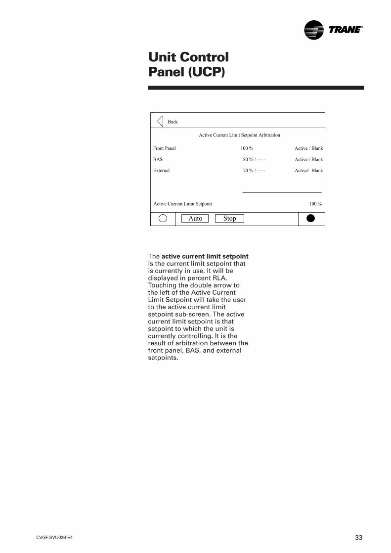
The active current limit setpointis the current limit setpoint thatis currently in use. It will bedisplayed in percent RLA.Touching the double arrow tothe left of the Active CurrentLimit Setpoint will take the userto the active current limitsetpoint sub-screen. The activecurrent limit setpoint is thatsetpoint to which the unit iscurrently controlling. It is theresult of arbitration between thefront panel, BAS, and externalsetpoints.
CVGF-SVU02B-E434
Unit ControlPanel (UCP)
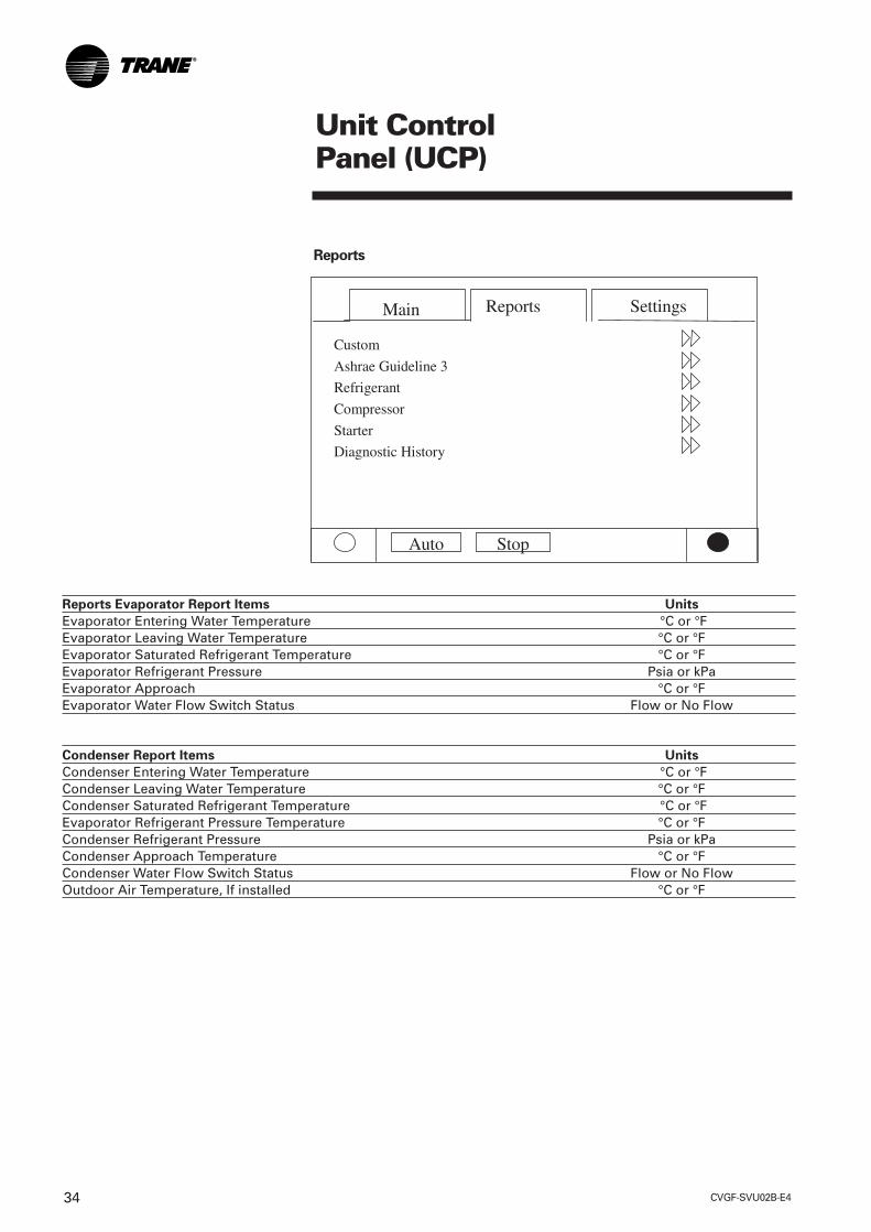
Reports Evaporator Report Items Units
Evaporator Entering Water Temperature °C or °FEvaporator Leaving Water Temperature °C or °FEvaporator Saturated Refrigerant Temperature °C or °FEvaporator Refrigerant Pressure Psia or kPaEvaporator Approach °C or °FEvaporator Water Flow Switch Status Flow or No Flow
Condenser Report Items Units
Condenser Entering Water Temperature °C or °FCondenser Leaving Water Temperature °C or °FCondenser Saturated Refrigerant Temperature °C or °FEvaporator Refrigerant Pressure Temperature °C or °FCondenser Refrigerant Pressure Psia or kPaCondenser Approach Temperature °C or °FCondenser Water Flow Switch Status Flow or No FlowOutdoor Air Temperature, If installed °C or °F
Reports

CVGF-SVU02B-E4 35
Unit ControlPanel (UCP)
Compressor Report Items Units
Compressor Starts: ###Compressor Running Time: Hour and minuteOil Differential Pressure Switch Open or ClosedOil Tank Temperature °C or °FVanes Position Percent openVanes Position Steps Steps
Motor Report Items Units
Percent RLA L1 L2 L3 Percent RLAAmps L1 L2 L3 AmpsVolts AB, BC, CA VacPower Consumption, If installed xxx kWLoad Power Factor, If installed xxWinding Temperature A °C or °FWinding Temperature B °C or °FWinding Temperature C °C or °F
ASHRAE Chiller Log Units
1. Current Time / Date HH:MM AM / PM MMM DD YYYY2. Chiller Mode Stopped / Running3. Amps L1 L2 L3 Amps4. Volts AB BC CA Volts5. Active Chiller Water Set Point F/ C6. Active Current Limit Set Point %7. Refrigerant Type 134a8. Compressor Starts 09. Compressor Running Time 0:0010. Oil Tank Temperature F/ C11. Evaporator Entering Water Temperature F/ C12. Evaporator Leaving Water Temperature F/ C13. Evaporator Saturated Refrigerant Temperature F/ C14. Evaporator Saturated Refrigerant Pressure PSIG / kPa15. Evaporator Approach Temperature F/ C16. Evaporator Water Flow Switch Status Flow / No Flow17. Condenser Entering Water Temperature F/ C18. Condenser Leaving Water Temperature F/ C19. Condenser Saturated Refrigerant Temperature F/ C20. Condenser Refrigerant Pressure PSIG / kPa21. Condenser Approach Temperature F/ C22. Condenser Water Flow Switch Status Flow / No Flow
CVGF-SVU02B-E436
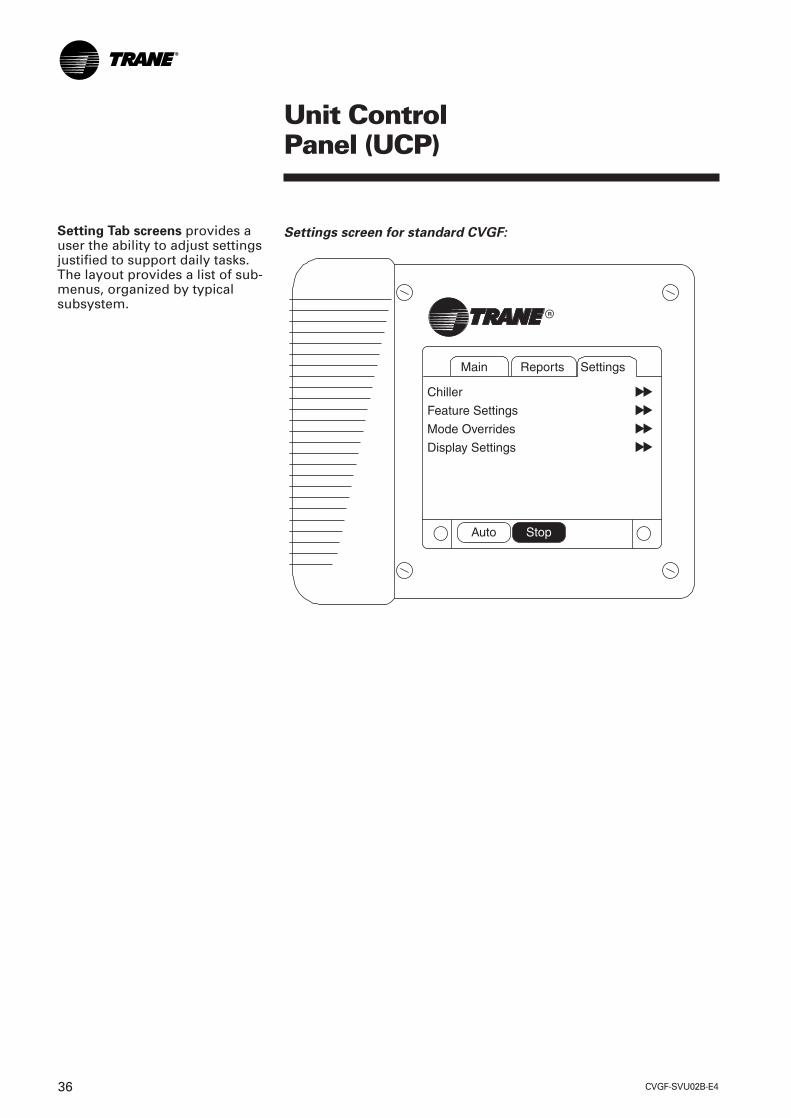
Setting Tab screens provides auser the ability to adjust settingsjustified to support daily tasks.The layout provides a list of sub-menus, organized by typicalsubsystem.
Unit ControlPanel (UCP)
Settings screen for standard CVGF:

CVGF-SVU02B-E4 37
Unit ControlPanel (UCP)
ChillerDescription Units notes
1. Front Panel Control Type (Chilled Water, Hot Water), Chilled Water default 2. Front Panel Chilled Water Setpoint Temperature 13. Front Panel Current Limit Setpoint Percent 24. Front Panel Base Load Command On or Auto6. Front Panel Base Load Setpoint Percent6. Differential to Start Temperature7. Differential to Stop Temperature8. Setpoint Source (none, use front panel, override BAS), none default
Feature SettingsDescription Units
1. Chilled Water Reset (Constant, Outdoor, Return, Disable), Disable Percent2. Return Reset Ratio Temperature3. Return Start Reset Temperature4. Return Maximum Reset Temperature5. Outdoor Reset Ratio Percent6. Outdoor Start Reset Temperature7. Outdoor Maximum Reset Temperature8. External Chilled Water Setpoint (Enable, Disable), Disable9. External Current Limit Setpoint (Enable, Disable), Disable10. External Base Loading Setpoint (Enable, Disable), Disable
Notes:1. Temperatures will be adjustable to 0.1 degree F or C. The Main Processor provides the minimum and maximum allowable value.2. Adjustable to the nearest whole number percent. The Main Processor provides the minimum and maximum allowable value.

CVGF-SVU02B-E438
Unit ControlPanel (UCP)
Mode Overrides
Description Units Default Monitor Value Notes
1. Compressor Control Signal (Auto, Manual) Auto Percent Vane Position[0-100] )
7
2. Evaporator Water Pump (Auto, On), Auto 1) Evaporator Flow status2) Override Time Remaining 3
3. Condenser Water Pump (Auto, On), Auto 1) Condenser Flow status2) Override Time Remaining 3
4. Oil Pump (Auto, On), Auto 1) Differential pressure2) Override Time Remaining 3
5. Clear Restart Inhibit Timer
Display Settings
Description Units Notes
1. Date Format (“mmm dd, yyyy”, “dd-mmm-yyyy”),2. Date “mmm dd, yyyy” 43. Time Format (12-hour, 24-hour), 12-hour4. Time of Day HH:mm 45. Keypad and Display Lockout (Enable, Disable), Disable 56. Display Units (SI, English), English7. Pressure Units Absolute / Guage8. Language (English, Selection 2, Selection 3), English 6
Notes:3. Terminates with 10 minutes if inactivity.4. The Date and Time setup screen formats deviate slightly from the standard screens defined above. See the time and date section for further details.5. Enables a DynaView™ Lockout screen. All other screens timeout in 30 minutes to this screen when enabled. The DynaView™ Lockout Screen displays
a 0-9 keypad to permit the user to exit the lockout with a fixed password (1x5 x 9 + Enter). See lockout section for further details.6. Language choices are dependent on what has been setup in the Main Processor. Language selections will include English and two alternate as
loaded by TechView™. Language shall always be the last setting listed on the Display Settings menu. This will allow a user to find language selectionif looking at an unrecognizable language.
7. Manual Compressor Control allows an operator to override the Auto Control and manually control the compressor while in operation. This is notactive during Stop mode.
Evaporator Leaving WaterTemperature
CVGF-SVU02B-E4 39
Unit ControlPanel (UCP)
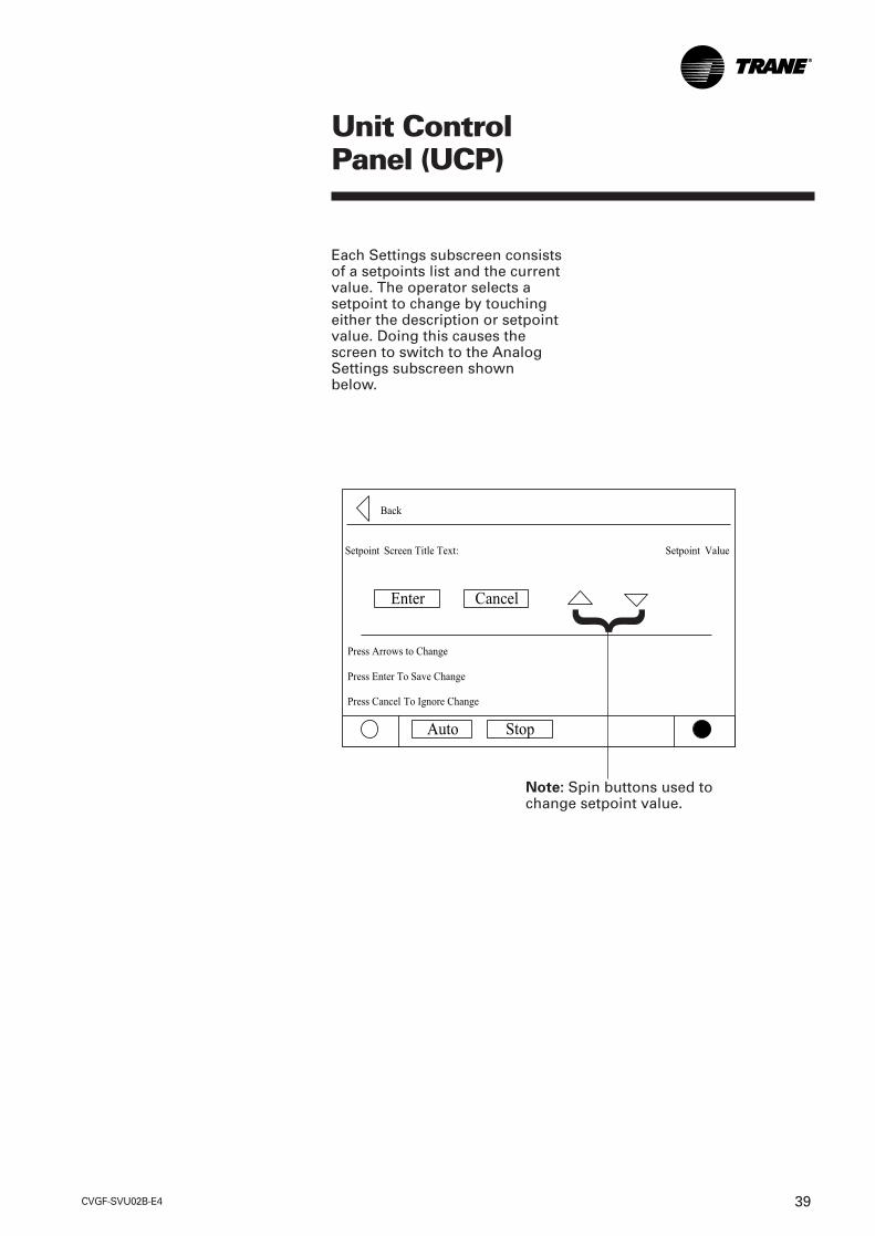
Each Settings subscreen consistsof a setpoints list and the currentvalue. The operator selects asetpoint to change by touchingeither the description or setpointvalue. Doing this causes thescreen to switch to the AnalogSettings subscreen shownbelow.
{
Note: Spin buttons used tochange setpoint value.
CVGF-SVU02B-E440
Unit ControlPanel (UCP)
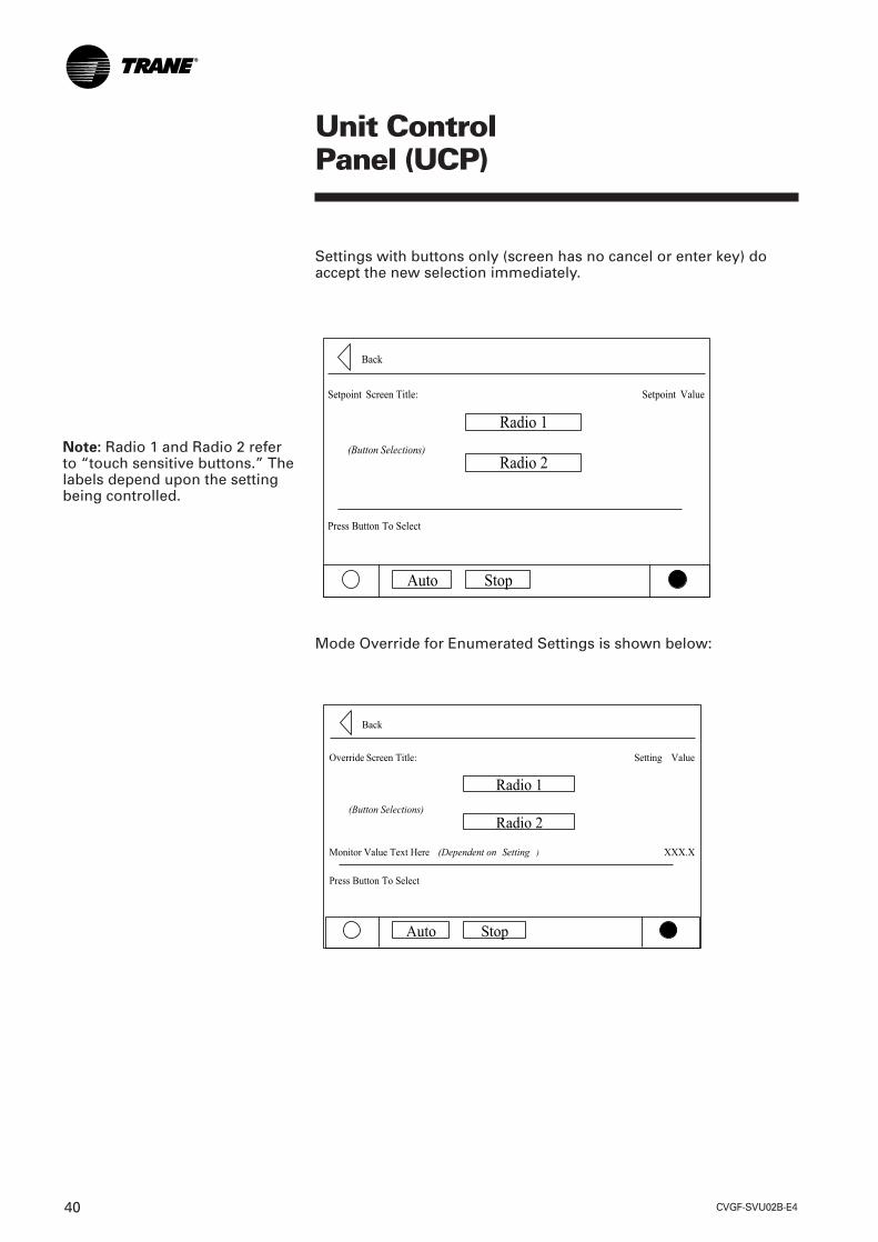
Settings with buttons only (screen has no cancel or enter key) doaccept the new selection immediately.
Mode Override for Enumerated Settings is shown below:
Note: Radio 1 and Radio 2 referto “touch sensitive buttons.” Thelabels depend upon the settingbeing controlled.
CVGF-SVU02B-E4 41
Unit ControlPanel (UCP)
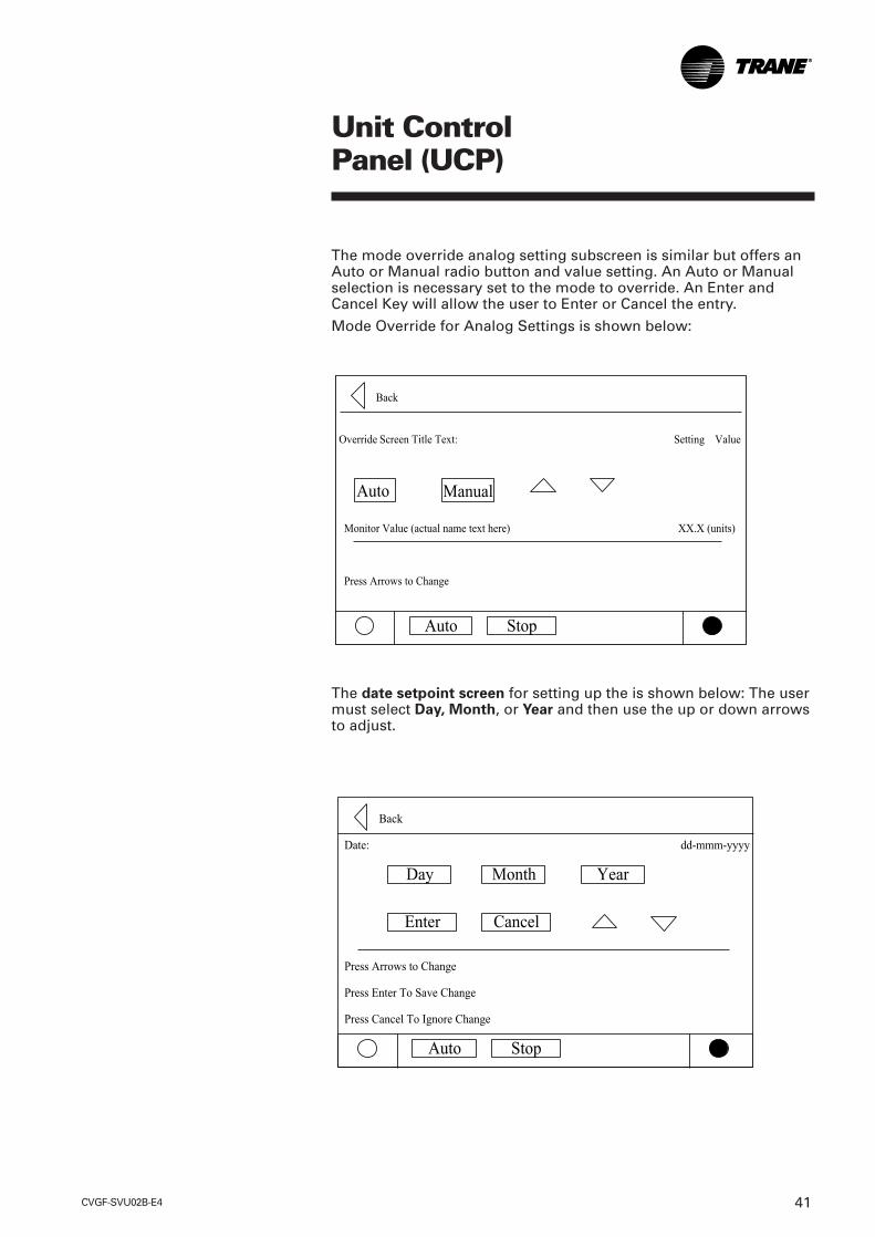
The mode override analog setting subscreen is similar but offers anAuto or Manual radio button and value setting. An Auto or Manualselection is necessary set to the mode to override. An Enter andCancel Key will allow the user to Enter or Cancel the entry.
Mode Override for Analog Settings is shown below:
The date setpoint screen for setting up the is shown below: The usermust select Day, Month, or Year and then use the up or down arrowsto adjust.

CVGF-SVU02B-E442
Unit ControlPanel (UCP)
The time setpoint screen with a 12 hour format is shown below: Theuser must select Hour, or Minute and then use the up or downarrows to adjust. Adjusting hours will also adjust am and pm.
Note: The 24 hour format setpoint screen is similar with the am andpm not shown.
CVGF-SVU02B-E4 43
Unit ControlPanel (UCP)
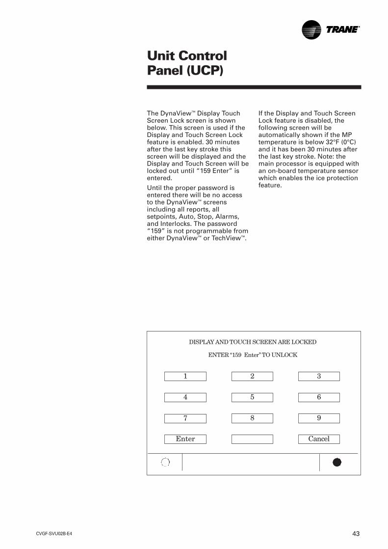
The DynaView™ Display TouchScreen Lock screen is shownbelow. This screen is used if theDisplay and Touch Screen Lockfeature is enabled. 30 minutesafter the last key stroke thisscreen will be displayed and theDisplay and Touch Screen will belocked out until “159 Enter” isentered.
Until the proper password isentered there will be no accessto the DynaView™ screensincluding all reports, allsetpoints, Auto, Stop, Alarms,and Interlocks. The password“159” is not programmable fromeither DynaView™ or TechView™.
If the Display and Touch ScreenLock feature is disabled, thefollowing screen will beautomatically shown if the MPtemperature is below 32°F (0°C)and it has been 30 minutes afterthe last key stroke. Note: themain processor is equipped withan on-board temperature sensorwhich enables the ice protectionfeature.
1 2 3
4 5 6
7 8 9
Enter Cancel
DISPLAY AND TOUCH SCREEN ARE LOCKED
ENTER “159 Enter”TO UNLOCK

CVGF-SVU02B-E444
If the chiller approaches fullcurrent, the evaporatortemperature drops too low, orthe condenser pressure rises toohigh, Tracer CH530 Adaptive.Control logic limits the loadingof the chiller to prevent thechiller from shutting down on asafety limit. These limits mayprevent the chiller from reachingthe load requested by the BaseLoading signal.
Base Loading Control is basicallya variation of the current limitalgorithm. During base loading,the leaving water controlalgorithm provides a loadcommand every 5 seconds. Thecurrent limit routine may limitthe loading when the current isbelow setpoint. When thecurrent is within the deadband ofthe setpoint the current limitalgorithm holds against thisloading command.
If the current exceeds thesetpoint, the current limitalgorithm unloads.
The “Capacity Limited By HighCurrent” message normallydisplayed while the current limitroutine is active is suppressedwhile base loading.
Base loading can occur usingTracer or an external signal.
Tracer or an external signal BaseLoading: Current SetpointRange: (20 - 100) percent RLA.Base Loading requires TracerSummit and an optional TracerCommunications Module (LLID)
Base Loading ControlAlgorithm
This feature allows an externalcontroller to directly modulatethe capacity of the chiller. It istypically used in applicationswhere virtually infinite sourcesof evaporator load andcondenser capacity are availableand it is desirable to control theloading of the chiller. Twoexamples are industrial processapplications and cogenerationplants.
Industrial process applicationsmight use this feature to imposea specific load on the facility’selectrical system.
Cogeneration plants might usethis feature to balance thesystem’s heating, cooling andelectrical generation. All chillersafeties and adaptive controlfunctions are in full effect whenBase Loading control is enabled.
Base LoadingControl Algorithm
CVGF-SVU02B-E4 45
Tracer Base Loading
The Tracer commands the chillerto enter the base load mode bysetting the base load moderequest bit ON. If the chiller isnot running, it will startregardless of the differential tostart. While the unit is running inbase loading, it will report thatstatus back to the Tracer. Whenthe Tracer removes the baseload mode request, the unit willcontinue to run, using thenormal chilled water controlalgorithm, and will turn off, onlywhen the differential to stop hasbeen satisfied.
External Base Base Loading
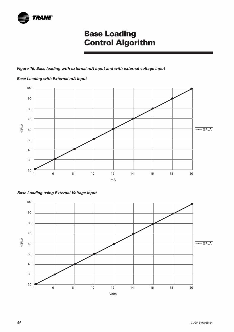
The CH530 accepts 2 inputs towork with external base loading.The binary input is at 1A18Terminals J2-1 and J2-2(Ground) which acts as a switchclosure input to enter the baseloading mode. The second input,an analog input, is at 1A17terminals J2-2 and J2-3 (Ground)which sets the external baseloading setpoint, and can becontrolled by either a 2-10Vdc or4-20mA Signal. At startup theinput type is configured.
The graphs in Figure 16 showthe relationship between inputand percent RLA. While in baseloading the active current limitsetpoint is set to the Tracer orexternal base load setpoint,providing that the base loadsetpoint is not equal to 0 (or outof range). If it is out of range, thefront panel current limit setpointis used. During base loading, alllimits are enforced with theexception of current limit.DynaView™ displays themessage “Unit is Running BaseLoaded.”
An alternative and less radicalapproach to Base Loadingindirectly controls chillercapacity. Artificially load thechiller by setting the chilledwater setpoint lower than it iscapable of achieving. Then,modify the chiller’s load byadjusting the current limitsetpoint. This method providesgreater safety and controlstability in the operation of thechiller because it has theadvantage of leaving the chilledwater temperature control logicin effect.
The chilled water temperaturecontrol logic responds quicker todramatic system changes, andcan limit the chiller loading priorto reaching an Adaptive Controllimit point.
Base LoadingControl Algorithm
CVGF-SVU02B-E446
Base LoadingControl Algorithm
Figure 16. Base loading with external mA input and with external voltage input
Base Loading with External mA Input
%R
LA
100
90
80
70
60
50
40
30
204 6 8 10 12 14 16 18 20
mA
—— %RLA
Base Loading using External Voltage Input
%R
LA
100
90
80
70
60
50
40
30
204 6 8 10 12 14 16 18 20
Volts
—— %RLA

CVGF-SVU02B-E4 47
The Control Panel Devices tablecorresponds to the same devicedesignators. Optional controlsare present when a specificoptional controls package isspecified. Optional controlspackages are: OPST OperatingStatus, GBAS Generic BuildingSystems, EXOP Extendedoperation, and TRMM Tracercommunications. 1A1, 1A4, 1A5,1A6, 1A9, 1A13, 1A19, 1A26 arestandard and present in allconfigurations. Other modulesvary depending on machineoptional devices.
Control SystemComponents
Control System Components
Control Panel Internally mounteddevices
For visual identification InternalControl Panel mounted devicesare identified by their respectiveschematic designation number.Control panel items are markedon the inner back panel in thecontrol panel (Figure 17).
Figure 17. Control panel components layout
OPTIONAL
OPTIONAL
OPTIONAL
OPTIONAL
OPTIONAL
OPTIONAL
OPTIONAL
OPTIONAL
OPTIONAL

CVGF-SVU02B-E448
Chilled and Condenser WaterFlow Interlock Circuits
Proof of chilled water flow forthe evaporator is made by theclosure of flow switch 5S1 andthe closure of auxiliary contacts5K1 on terminals 1X1-5 and 1A6-J3-1 and J3-2. Proof ofcondenser water flow for thecondenser is made by theclosure of flow switch 5S2 andthe closure of auxiliary contacts5K2 on terminals 1X1-6 and 1A6-J2-1 and J2-2.
Head Relief Request OutputWhen the chiller is running inCondenser Limit Mode or inSurge Mode, the head reliefrequest relay on the 1A9-J2-6 toJ2-4 will be energized and canbe used to control or signal for areduction in the enteringcondenser water temperature.This is designed to prevent highrefrigerant pressure trip-outsduring critical periods of chilleroperation.
Maximum Capacity RelayWhen the chiller has beenoperating at maximum capacityfor over a 10 minute (TechView™
adjustable) time period this relaywill activate. Also upon beingless than maximum capacity for10 minutes, this relay willdeactivate. This is located atLLID 1A9-J2-1 and J2-3.
Compressor Running RelayRelay activates while thecompressor is running.
Control SystemComponents

CVGF-SVU02B-E4 49
Control SystemComponents
Control Panel Devices
Standard Devices
Controls Field Connection Description Package Purpose Point Terminals
1A1 Power Supply Standard #1 Converts 24 vac to 24 Vdc not for field useStandard High Pressure Cutout not for field use
Standard Relay #1 Chilled water pump J2-1 NO, J2-2 NC,(Relay #1) J2-3 common
Standard Relay #2 Condenser water pump control J2-4 NO, J2-5 NC,(Relay #2) J2-6 common
Standard Input 1 Condenser Flow Input J3-2 Condenser water flow switch
Standard Input 2 Evaporator Flow Input J2-2 Chilled waterflow switch
Standard Relay #1 Maximum Capacity Relay J2-1 NO, J2-2 NC, J2-3 common
Standard Relay #2 Head Relief Request Relay J2-4 NO, J2-5 NC,J2-6 common
Standard Relay #3 Oil Pump J2-7 NO, J2-8 NC, J2-9 common
Standard Signal #1 J2-3 Binary Input Signal #1,J2-4 Ground
Standard Signal #1 External Auto Stop, J2-1 Binary Input Signal #1, J2-2 Ground
Standard Signal #2 Emergency stop J2-3 Binary Input Signal #2,J2-4 Ground
1F1 Standard not for field use
1F2 Standard not for field use
1T1 Standard not for field use
1Q1 Standard not for field use
1Q3 Standard not for field use
1X1 Terminal Block Standard
1A4 Quad High VoltageInput
1A19 Standard Dual LVBinary input module
1A5 Quad RelayOutput modules1A5 Quad RelayOutput modules1A6 Dual High VoltageInput1A6 Dual High VoltageInput1A9 Standard QuadRelay Output Status1A9 Standard QuadRelay Output Status1A9 Standard QuadRelay Output Status
1A13 Dual LV Binaryinput module1A13 Dual LV Binaryinput module
Oil Differential PressureSwitch
LLID Power Supply TransformerPrimary Circuit protectionOil Pump Motor Branch CircuitprotectionControl Panel PowerTransformer ; 120:24Vac Circuit Breaker CompressorMotor Controller Control PowerBranch CircuitCircuit Breaker – Module [-LLID] Power Supply BranchCircuitControl Panel Terminal Block,Flow switch connections
1X1-5 Chilled water flowswitch input1X1-6 Condenser water flowswitch input

CVGF-SVU02B-E450
EXOP Extended Operation Option
The following modules (1A17, 1A18) are provide when this control package is specified.
EXOP Signal #1 J2-2 Input #1, J2-3 Ground
EXOP Signal #2 Refrigerant monitor inputs J2-5 Input #2, J2-6 Ground
EXOP Signal #1 External Base Loading J2-1 Binary Input Signal #1, Enable or Disable input, points J2-2 Ground
EXOP Signal #2 External Hot Water Control J2-3 Binary Input Signal #2,Enable or Disable input J2-4 Ground
Refrigerant Monitor Input 1A17Analog type input 4-20ma input signal to the 1A17 J2-5 to J2-6 (ground). This represents 0-100 ppm.
TRMM TRM4 TRM5 (Tracer Comm 4, Comm 5 interface)TRM4 / TRM5 Tracer Communications J2-1 COMM+, J2-2 COMM -J2-3,
COMM +J2-4, COMM -,
CDRP (Condenser Refrigerant Pressure Output) (1A15)
CDRP Signal #2 J2-4 Output #2, J2-6 Ground
CDRP Signal #1 J2-1 Output #1, J2-3 Ground
1A17 Optional Dual AnalogInput/Output Module1A17 Optional Dual AnalogInput/Output Module1A18 Optional Dual LV Binaryinput module1A18 Optional Dual LV Binaryinput module
External Base LoadingSetpoint input
1A14 OptionalCommunicationInterface Module
1A15 Optional Dual AnalogInput/output Module
Condenser RefrigerantPressure output
Control SystemComponents
OPST Operation Status Option
Relay output module 1A8 provide relay outs as shown:
OPST Relay #1 MAR Alarm Relay, J2-1 NO, J2-2 NC,(Non-Latching) J2-3 common
OPST Relay #2 Limit Warning Relay, J2-4 NO, J2-5 NC, J2-6 common
OPST Relay #3 MMR Alarm Relay J2-7 NO, J2-8 NC, (Latching) J2-9 common
OPST Relay #4 Compressor running relay J2-10 NO, J2-11 NC, J2-12 common
1A8 Optional Quad RelayOutput Status1A8 Optional Quad RelayOutput Status1A8 Optional Quad RelayOutput Status1A8 Optional Quad RelayOutput Status
1A15 Optional Dual AnalogInput/output Module
Percent RLA CompressorOutput

CVGF-SVU02B-E4 51
CDRP Refrigerant PressureOutput Option 1A15:
Refrigerant Pressure Output canbe configured at commissioningto correspond to either A) theabsolute condenser pressure, orB) the differential pressure of theevaporator to condenserpressures.
This output is located at 1A15-J2-4(+) to J2-6 (ground)
The Output can source amaximum of 22 mA of current.
A) Condenser Pressure Output.2 to 10 Vdc corresponds to 0Psia to the HPC (in Psia) setting.
Temperature basedOn standard machines thePercent Condenser PressureIndication Output is based on theSaturated Condenser Refrigerantand a temperature to pressureconversion is made.
If the Condenser SaturatedTemperature goes out of rangedue to an open or short, apressure sensor diagnostic willbe called and the output will alsogo to the respective out of rangevalue. That is, for an out of rangelow on the sensor, the outputwill be limited to 2.0 Vdc. For anout of range high on the sensor,the output will be limited to 10.0Vdc.
Control SystemComponents
Figure 18.
CAP10 vdc
2 vdc
0 PSIA0 Percent
HPC in PSIA100 Percent

CVGF-SVU02B-E452
Control SystemComponents
Figure 19. Delta pressure setting
B) Refrigerant Differential PressureIndication Output:A 2 to 10 Vdc analog output isprovided instead of the previouscondenser pressure outputsignal. This 2 signal correspondsto a predetermined minimumand maximum pressure settingssetup at commissioning of thisfeature. This relationship can bealtered using TechView™ ifrequired.
The “Minimum Delta Pressure“is typically set to 0 psi and willthen correspond to 2 Vdc. The“Maximum Delta Pressure “ istypically set to 30 psi andcorresponds to 10 Vdc.
The Minimum Delta PressureCalibration setting has a range of0-400 psid (0-2758 kPa) inincrements of 1 psid (1kPa). TheMaximum Delta PressureCalibration setting has a range of1-400 psid (7-2758 kPa) inincrements of 1 psid (1kPa). Thecondenser refrigerant pressure isbased on the CondenserRefrigerant Temperature sensor.The evaporator refrigerantpressure is based on theSaturated Evaporator RefrigerantTemperature Sensor.
10 vdc
2 vdc
Minimum DeltaPressure Setting
Maximum DeltaPressure Setting

CVGF-SVU02B-E4 53
Percent RLA Output 2 to 10 Vdc corresponding to 0to 120% RLA. With a resolutionof 0.146%. The Percent RLAOutput is polarity sensitive.
The following graph illustratesthe output:
Control SystemComponents
GBAS (Generic Building Automation System)
GBAS Signal #1 Percent RLA Compressor Output J2-1 Output #1, J2-3 Ground
GBAS Signal #2 J2-4 Input #2, J2-6 Ground
GBAS Signal #1 J2-2 Input #1, J2-3 Ground
GBAS Signal #2 External Current limit Setpoint J2-5 Input #2, J2-6 Ground
Figure 20. Voltage versus percent RLA
Voltage versus Percent RLA
Voltage
Per
cen
t R
LA
1A15 Optional DualAnalog Input/outputModule1A15 Optional DualAnalog Input/outputModule
1A16 Optional DualAnalog Input/outputModule1A16 Optional DualAnalog Input/outputModule
Condenser Rerigerant Pressureor Evaporator/Condenserdifferential
Chilled Water Reset input, orExternal Chiller Water Setpoint

CVGF-SVU02B-E454
External Chilled Water Setpoint(ECWS)The External Chilled WaterSetpoint allows the chilled watersetpoint to be changed from aremote location. The ExternalChilled Water Setpoint is foundon 1A16 J2-2 to J2-3 (ground).2-10 Vdc and 4-20 mAcorrespond to a 0 to 65°F (-17.8to 18.3°C) CWS range.
External Current Limit Setpoint The External Current Limit is anoption that allows the currentlimit setpoint to be changedfrom a remote location. TheExternal Limit Setpoint is foundon 1A16 J2-5 to J2-6 (ground),2-10 Vdc and 4-20 mA eachcorrespond to a 40 to 120percent RLA range. CH530 limitsthe maximum ECLS to 100percent.
Module Characteristics
1A1, Power Supply :Unit Control Power SupplyModule Converts 27 Vac to 24Vdc.
Power Input Voltage: 23VRMSminimum, 27VRMS Nominal,30VRMS maximum
Frequency: 50-60 Hz
Current: Full load 27 Vac – 4.30 A(RMS)
Inrush 27 Vac (RMS) ~ 30A(RMS)
Power Output: Class II Voltage 24Vdc, Rated Current 2.44 Amps.
1A4, 1A6, Dual high VoltageBinary input module: Binary Input Signal #1 J2-1 to 2
Binary Input Signal #2 J3-1 to 2
High Voltage Binary Input: OffVoltage: 0 to 40 Vac RMS , OnVoltage: 70 to 276 Vac RMS
Input is not polarity sensitive(Hot and neutral can beswitched), Input impedance 130Kto 280K ohms
14-26 AWG with a maximum oftwo 14 AWG
Power, 24 +/- 10 percent Vdc, 20mA maximum. Trane IPC3protocol. J1-1 +24Vdc, J1-2Ground, J1-3 COMM +, J1-4COMM -
Control SystemComponents

CVGF-SVU02B-E4 55
1A5, 1A8, 1A9 Quad Relay OutputStatus: Relay #1 J2-1 NO, J2-2 NC, J2-3common
Relay #2 J2-4 NO, J2-5 NC, J2-6common
Relay #3 J2-7 NO, J2-8 NC, J2-9common
Relay #4 J2-10 NO, J2-11 NC,J2-12 common
Relay Outputs: at 120 Vac: 7.2Amps resistive, 2.88 Amps pilotduty, 1/3 HP, 7.2 FLA, at 240 Vac:5 Amps general purpose 14-26AWG, two 14 AWG MaximumPower, 24
±10 percent Vdc, 100 mAmaximum. Trane IPC3 protocol.
1A13, 1A18, 1A19, 1A24 DualBinary input module: J2-1 Binary Input Signal #1, J2-2Ground, J2-3 Binary Input Signal#2, J2-4 Ground
Binary Input: Looks for a drycontact closure. Low Voltage 24V12 mA.
14 - 26 AWG with a maximum oftwo 14 AWG
Power, 24 +/- 10 percent Vdc, 40mA maximum Trane IPC3protocol.
1A14 Communication interfaceModule Power, 24 ± 10 percent Vdc, 50mA maximum. Trane IPC3protocol.
Control SystemComponents
1A14 Communication PolarityJ1-1 +24 Vdc J2-1 COMM +. J11-1+24 VdcJ1-2 Ground J2-2 COMM - J11-2 GroundJ1-3 COMM + J2-3 COMM + J11-3 COMM +J1-4 COMM - J2-4 COMM - J11-4 COMM

CVGF-SVU02B-E456
1A15, 1A16, 1A17, Dual AnalogInput/output Module;Analog Output: The AnalogOutput is a voltage only signal.2-10 Vdc at 22mA
J2: 14 - 26 AWG with amaximum of two 14 AWG
J2-1 Output #1 to J2-3 (ground),J2-4 Output #2 to J2-6 (ground).
CH530 provides a 2-10 Vdcanalog signals as Outputs. TheOutput’s maximum sourcecapability is 22mA. Themaximum recommended lengthto run this signal is included inthe table below.
Analog Input:The analog input can besoftware switched between avoltage input or a current input.When used as a current input a200 Ohm load resistor isswitched in.
0-12 Vdc or 0-24 mA Analog InputsCH530 accepts either a 2-10 Vdcor 4-20 analog input suitable forcustomer external control. Thetype is determined at unitcommissioning during featureinstallation.
J2: 14-26 AWG with a maximumof two 14 AWG
J2-2 Input #1 to
J2-3 (ground).
J2-5 Input #2 to
J2-6 (ground).
Power, 24 +/- 10 percent Vdc, 60mA maximum, Trane IPC3protocol.
Control SystemComponents
Maximum Length to Run external Output signals
Gauge Ohms per Foot Length (Feet) Length (Meters)14 0.00 2823 1062.7 32416 0.004489 668.3 203.818 0.007138 420.3 128.120 0.01135 264.3 80.622 0.01805 166.3 50.724 0.0287 104.5 31.926 0.04563 65.7 2028 0.07255 41.4 12.6
Note: the above table is for copper conductors only.

CVGF-SVU02B-E4 57
Note: If the chiller is operating ina limit mode (current limit,condenser limit, evaporatorlimit, and so forth), the limitoperation has priority over allDynaView™ manual modes ofoperation.On each CH530 power-up, theinlet guide vanes are driven fullclosed to recalibrate the zeroposition (steps) of the Steppermotor vane actuator.
Motor Temperature SensorModuleThe motor temperature module1A26 connects using unit wiringto the three motor windingtemperature sensors. Thismodule is located in the controlpanel where the module isconnected to the IPC bus.
Temperature SensorsEvaporator entering 4R6Evaporator leaving 4R7Condenser entering 4R8Condenser leaving 4R9Oil temperature 4R5Outdoor air 4R13Evaporator saturated refrigerant4R10Condenser saturated refrigerant4R11
Probe Operating TemperatureRange -40 to 121°C
Accuracy± 0.250°C over therange - 20 to 50°C ± 0.50°C overthe range -40 to 121°C
Starter ModuleIn the hierarchy of modules theStarter module 2A1 (1A23 whencustomer-supplied starterspecified) is second only to theDynaView™.
The starter module is present inall starter selections. Thisincludes Wye Delta, Across theLine, and Solid State whetherremote unit mounted or suppliedby others. The starter moduleprovides the logic to provide themotor protection for currentoverload, phase reversal, phaseloss, phase imbalance, andmomentary power loss.
Control SystemComponents
CVGF-SVU02B-E458
Electrical SequenceThis section will acquaint theoperator with the control logicgoverning chillers equipped withTracer CH530 control systems.
Note: The typical wiringdiagrams are representative ofstandard units and are providedonly for general reference. Theymay not reflect the actual wiringof your unit. For specificelectrical schematic andconnection information, alwaysrefer to the wiring diagrams thatshipped with the chiller.
With the supply powerdisconnect switch or circuitbreaker (2Q1 or 2K3) on, 115-voltcontrol power transformer 2T5and a 15-amp starter panel fuse(2F4 ) to terminal (2X1-1) starterpanel to terminal 1X1-1 in thecontrol panel. From this point,control voltage flows to:
1. Circuit Breaker 1Q1 whichprovides power to the startermodule (2A1) relay outputsand the High Pressure Cutoutswitch (4S1).
2. Circuit Breaker 1Q3 whichprovides power toTransformer (1T1) which stepsdown the 115 Vac to 24 Vac.This 24 Vac then powers the24 Vdc power supply 1A1, and1A2 if present. The 24 Vdc isthen connected to all modulesusing the IPC Bus providingmodule power. 1Q3 alsoprovides power to theexternal chiller water proof offlow device connectedbetween terminal block 1X1-5 to 1A6-J3-2, andcondenser water proof of flowdevice connected at 1X1-6 to1A6-J2-2.
3. The DynaView™ displaymodule 1A22, receives 24 Vdcpower from the IPC bus.
Control SystemComponents

CVGF-SVU02B-E4 59
CH530 and Wye-DeltaStarter Control Circuits(Sequence of Operation)
Logic Circuits within the variousmodules will determine thestarting, running, and stoppingoperation of the chiller. Whenoperation of the chiller isrequired the chiller mode is setat ‘‘Auto.” Using customer-supplied power, the chilled waterpump relay (5K1) is energized bythe 1A5 Module output at 1A5-J2-4, and chilled water flow mustbe verified within 4 minutes 15seconds by the 1A6 module. Themain processors logic decides tostart the chiller based on thedifferential to start setpoint. Withthe differential to start criteriamet module 1A5 then energizesthe condenser water pump relay(5K2) using customer-suppliedpower at 1A5 J2-1.
Based on the restart inhibitfunction and the differential tostart setpoint, oil pump (4M3)will be energized by 1A9 module(1A9-J2-7). The oil pressureswitch must be closed for 30continuous seconds andcondenser water flow verifiedwithin 4 minutes 15 seconds forthe compressor start sequenceto be initiated.
When less than 5 secondsremain before compressor start,a starter test is conducted toverify contactor state prior tostarting the compressor. Thefollowing test or start sequenceis conducted for “Wye-Delta”starters:
1. Test for transition completecontact open (1A23X or2A1-J12-2) –160 to 240 msec.An MMR diagnostic will begenerated if the contact isclosed.
2. Delay time - 20 msec.
3. Close start contactor (2K1)and check for no current - 500msec. If currents are detected,the MMR diagnostic ‘‘StarterFault Type I’’ is generated andcloses for one second.
4. Delay time - 200 msec.(Opens 2K1).
5. Close shorting contactor,(2K3) and check for no current(1A23 or 2A1 J4-1) for onesecond. If currents aredetected the MMR diagnostic‘‘Starter Fault Type II’’ isgenerated. (Starter Integritytest)
6. If no diagnostics aregenerated in the above tests,the stop relay (2A1- J10) isclosed for two seconds andthe start relay (2A1-J8) isclosed to energize the startcontactor (2K1).
Control SystemComponents

CVGF-SVU02B-E460
The shorting contactor (2K3)has already been energizedfrom (F) above. Thecompressor motor (4M1) startsin the “Wye” configuration, anauxiliary contact (2K1-AUX)locks in the start contactor(2K1) coil.
7.After the compressor motorhas accelerated and themaximum phase current hasdropped below 85 percent ofthe chiller nameplate RLA for1.5 seconds, the startertransition to the “Delta”configuration is initiated.
8.The transition contactor (2K4)is closed through relay 2A1-J2,placing the transition resistors(2R1, 2R2, and 2R3) in parallelwith the compressor motorwindings.
9.The shorting contactor (2K3) isopened through the openingof relay 2A1-J4 100 msec afterthe closure of the transitionrelay 2A1-J2.
10. The run contactor (2K2) isclosed through relay 2A1-J6,shorting out the transitionresistors 260 millisecondsafter the opening of theshorting relay 2A1-J4. Thisplaces the compressor motorin the “Delta” configurationand the starter module waitsto look for this transition for2.35 seconds through theclosure of the transitioncomplete contacts 2K2- AUXat module 2A1-J12 input.
11. The starter module must nowconfirm closure of thetransition complete contact(2K2- AUX) within 2.32 to2.38 seconds after the runrelay (2A1-J6) is closed.Finally, the transition relay(2A1-J2) is opened de-energizing the transitioncontactor (2K4) and thecompressor motor startingsequence is complete.
An MMR diagnostic will begenerated if the transitioncomplete contacts (2K2-AUX) donot close.
Now that the compressor motor(4M1) is running in the “Delta”configuration, the inlet guidevanes will modulate, openingand closing to the chiller loadvariation by operation of thestepper vane motor actuator(4M2) to satisfy chilled watersetpoint. The chiller continues torun in its appropriate mode ofoperation: Normal, Softload,Limit Mode, and so forth
Control SystemComponents
CVGF-SVU02B-E4 61
Control SystemComponents
If the chilled water temperaturedrops below the chilled water setpoint by an amount set as the“differential to stop” setpoint, anormal chiller stop sequence isinitiated as follows:
1. The inlet guide vanes aredriven closed for 50 seconds.
2. After the 50 seconds haselapsed, the stop relay (2A1-J10) and the condenser waterpump relays (1A5-J2) open toturn off. The oil pump motor(4B3) will continue to run for 1minute post-lube while thecompressor coasts to a stop.The chilled water pump willcontinue to run while theMain processor module(1A22) monitors leavingchilled water temperaturepreparing for the nextcompressor motor start basedon the “differential to start”setpoint.
If the <STOP> key is pressed onthe operator interface, the chillerwill follow the same stopsequence as above except thechilled water pump relay (1A5-J2) will also open and stop thechilled water pump after thechilled water pump delay timerhas timed out after compressorshut down.
If the “Immediate Stop” isinitiated, a panic stop occurswhich follows the same stopsequence as pressing the<STOP> key once except theinlet guide vanes are notsequence closed and thecompressor motor isimmediately turned off.

CVGF-SVU02B-E462
Machine Protection andAdaptive Control
Momentary Power Loss (MPL)ProtectionMomentary power loss detectsthe existence of a power loss tothe compressor motor andresponds by initiating thedisconnection of the compressormotor from the power source.
Power interruptions of less than30 line-cycles are defined asmomentary power losses. Testshave shown that these short-term power interruptions can bedamaging to the motor andcompressor if the chiller isreconnected to the line while themotor and line phases do notmatch. The chiller will be shutdown when a MPL is detectedand will display a non-latchingdiagnostic indicating the failure.
The oil pump will be run for thepost-lube time period whenpower returns. The compressorand compressor motor areprotected from damage fromlarge torques and inrushcurrents resulting fromreconnecting the compressormotor to the power sourcefollowing a momentary loss ofpower.
MPLs greater than 2 or 3 cyclesare detected resulting in unitshut down. Disconnection fromthe line is initiated within 6 line-cycles of the power loss. MPLprotection is active anytime thecompressor is in the runningmode. (The transition completeinput has been satisfied.)
Note: MPL is defaulted toenabled however can bedisabled, if required usingTechView™.
Machine Protectionand Adaptive
CVGF-SVU02B-E4 63
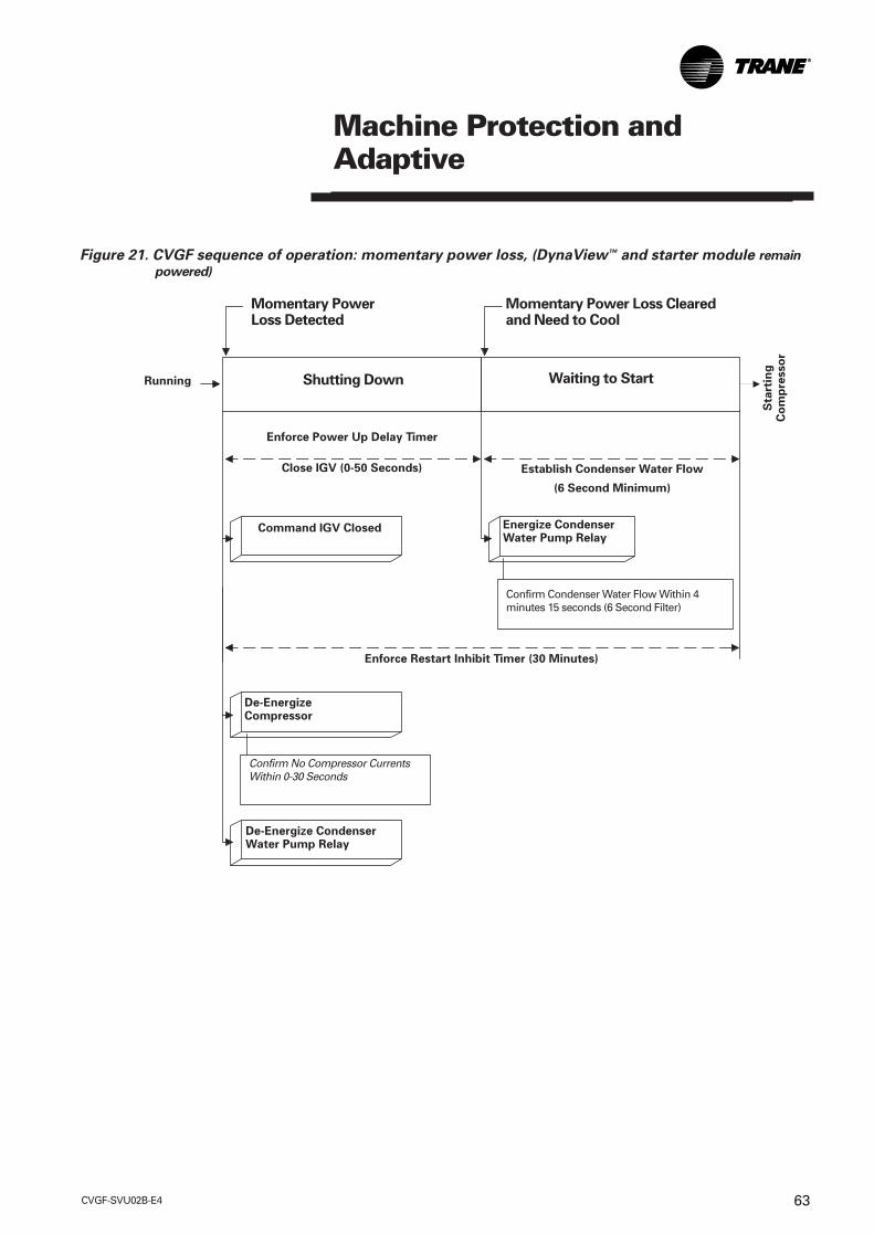
Figure 21. CVGF sequence of operation: momentary power loss, (DynaView™ and starter module remain
powered)
Momentary PowerLoss Detected
Momentary Power Loss Clearedand Need to Cool
Shutting Down Waiting to StartRunning
Sta
rtin
gC
om
pre
sso
r
Enforce Power Up Delay Timer
Establish Condenser Water Flow
(6 Second Minimum)
Close IGV (0-50 Seconds)
Command IGV Closed Energize CondenserWater Pump Relay
Confirm Condenser Water Flow Within 4minutes 15 seconds (6 Second Filter)
Enforce Restart Inhibit Timer (30 Minutes)
De-EnergizeCompressor
Confirm No Compressor CurrentsWithin 0-30 Seconds
De-Energize CondenserWater Pump Relay
Machine Protection andAdaptive

CVGF-SVU02B-E464
Machine Protection andAdaptive
Current OverloadProtection
Motor currents are continuouslymonitored for over currentprotection and locked rotorprotection. This protects thechiller from damage due tocurrent overload during startingand running modes but isallowed to reach full load amps.This overload protection logic isindependent of the current limit.The overload protection willultimately shut the unit downanytime the highest of the threephase currents exceeds the timetrip curve. A manual resetdiagnostic describing the failurewill be displayed.
Overload protection for themotor starts based on themaximum time to transitionpermitted for a particular motor.
Running Overload ProtectionIn the run mode, a time tripcurve is looked at to determine ifa diagnostic should be called.The starter LLID continuouslymonitors compressor linecurrents to provide runningoverload and locked rotorprotection.
Overload protection is based onthe line with the highest current.It triggers a manually resettablediagnostic shutting down thecompressor when the currentexceeds the specified time tripcurve. The compressor overloadtime trip curve is expressed as apercent of the RLA of thecompressor and is notadjustable:
Overload Must Hold = 102Percent RLA.
Overload Must Trip in 20 (+0 -3)seconds = 112 Percent RLA
(Note the above gives a nominal20 seconds must trip point of107 Percent RLA.)
Overload Must Trip in 1.5seconds = 140 Percent RLA(Nominal)
The time trip curve is as follows:
Figure 22. Overload time trip versus percent RLA
Nominal Triptime(Sec)
Minimum Triptime(Sec)
Maximum Triptime(Sec)
CVGF-SVU02B-E4 65
Current Limit Protection
Current Limit Protections exist toavoid motor current overloadand damage to the compressormotor during starting andrunning.
The Current Limit Setpoint (CLS)can be changed from: FrontPanel, External Analog input(with GBAS option), or Tracer(Tracer option). Tracer currentsetpoint has the highest priority,unless disabled in theDynaView™ Setpoint sourceoverride menu. The External CLShas second priority, and will beused if Tracer is disabled or notinstalled. The Front PanelSetpoint has the lowest priority,and will be used if Tracer and theExternal CLS are both disabled.
Compressor motor current iscontinuously monitored andcurrent is controlled using alimit function to prevent runninginto overload diagnostic trips.The current limit control logicattempts to prevent the motorfrom shutting down on adiagnostic trip by limitingcompressor current drawrelative to an adjustable currentlimit DynaView™ CLS.
This setpoint can also belowered to provide electricaldemand limiting on the unit asrequired. This could also be setto allow the chiller to continue torun at a lower load to avoidtripping off using a diagnostic.
The Current Limit function usesa PID algorithm (similar to theLeaving Water Temperaturecontrol) that allows the chiller torun at the CLS. At machinestartup, or with any setpointchange the new current limitsetpoint reached after thefiltered setpoint time elapses.The minimum current limitsetpoint is default set to 40percent RLA (20-100 percent).The filtering time default is setto 10 minutes (0-120 minutes);however these can be alteredusing the TechView™. Thisfiltered setpoint allows for stablecontrol if the Current Limitsetpoint is adjusted during a run.
Phase Loss ProtectionLoss of phase detection protectsthe chiller motor from damagedue to a single-phasingcondition. The controls will shutdown the chiller if any of thethree phase currents feeding themotor are lost. The shutdownwill result in a latchingdiagnostic indicating the failure.
Reverse RotationProtection
This function protects thecompressor from damagecaused by being driven in thereverse direction. Incorrectphase rotation detection resultsin a manually resettablediagnostic. Phase Reversalprotection default is set toenable, however can be disabledusing TechView™.
Machine Protection andAdaptive

CVGF-SVU02B-E466
Differential to Start or StopThe Differential to Start setpointis adjustable from 1 to 10°F (0.55to 5.5°C) and the Differential toStop setpoint adjustable from 1to 10°F (0.55 to 5.5°C). Bothsetpoints are with respect to theActive Chilled Water Setpoint.When the chiller is running andthe Leaving Water Temperature(LWT) reaches the Differential toStop setpoint the chiller will gothrough its shutdown sequenceto Auto. Reference Figure 10.
SoftLoadingSoftloading stabilizes the startupcontrol during the initial chillerpulldown. Soft loading is used tobring the building looptemperature from its start valueto the Chilled Water or Hot WaterSetpoint in a controlled manner.Without soft loading, the chillercontrols will load the chillerrapidly and use the full chillercapacity to bring the looptemperature to setpoint.Although the start temperatureof loop may have been high, theactual system load may be low.Thus, when the setpoint is metthe chiller must unload quicklyto the system load value. If it isnot able to unload quicklyenough, the supply watertemperature will drop belowsetpoint and may even cause thechiller to cycle off. Soft loadingprevents the chiller from goingto full capacity during thepulldown period. After thecompressor has been started,the starting point of the filteredsetpoint is initialized to the valueof the Evaporator Leaving Watertemperature and the percentRLA.
Minimum and MaximumCapacity LimitA Minimum Capacity can be setto limit the unloading ability ofthe compressor forcingdifferential stop to be reachedcycling the chillers. Minimumcapacity limit will be displayedwhen in this limit mode. Thisindicates when the chiller isrunning fully unloaded. Similarlya maximum capacity can be setto limit normal chilled watertemperature control. Themaximum capacity relay isenergized which is a signal usedby generic BAS systems to startanother chiller.
The minimum (default at 0percent) and maximum (defaultat 100 percent) capacity areadjustable using TechView™.
There are three independentSoftload setpoints:
• Capacity Control Softload Timedefault is to 10 minutes andsettable from 0-120 minutes.This setting controls the timeconstant of the Filtered ChilledWater Setpoint.
• Current Limit Control SoftloadTime default is 10 minutes andsettable from 0-120 minutes.This setting controls the timeconstant of the Filtered CurrentLimit Setpoint.
• Current Limit Softload StartingPercent default is 40 percentRLA and settable from 20-100percent. This setting controlsthe Starting point of theFiltered Current Limit Setpoint.
Note: TechView™ providesaccess to these three setpoints.
Machine Protection andAdaptive

CVGF-SVU02B-E4 67
Evaporator LimitEvaporator refrigeranttemperature is continuouslymonitored to provide a limitfunction that prevents lowrefrigerant temperature trips.This allows the chiller tocontinue to run at a reducedload instead of tripping off at theLow Refrigerant TemperatureCutout Setpoint (LRTC).
Evaporator limit could occurwith an initial pulldown of a looptemperature where thecondenser is colder than theevaporator (inverted start), andthe evaporator refrigeranttemperature may drop below theLRTC. This limit prevents theunit from shutting down on adiagnostic during this type ofpulldown. Another example is achiller that is low on refrigerantcharge. It will run with lowevaporator refrigeranttemperatures. This limit allowsthe chiller to continue to run at areduced load.
Evaporator Limit uses theEvaporator RefrigerantTemperature sensor in a PIDalgorithm (similar to the LeavingWater Temperature control) thatallows the chiller to run at theLRTC + 2 degree F (1.1°C).
When actively limiting machinecontrol “EvaporatorTemperature Limit” will bedisplayed as a suboperatingmode.
Leaving Water TemperatureCut-outLeaving water temperaturecutout is a safety control thatprotects the chiller from damagecaused by water freezing in theevaporator. The cutout setpointis factory set at 36°F (2.2°C)however is adjustable withTechView™. The cut-out strategyis illustrated in Figure 23.
The Leaving Water TemperatureCut-out Setpoint isindependently adjustable fromthe chilled water setpoint.Shutdown of the compressordue to violation of the LeavingWater Temperature Cut-outresults in an automaticallyresettable diagnostic (MAR). TheDynaView™ Operating Modeindicates when the LeavingWater Temperature Cut-outSetpoint conflicts with thechilled water temperaturesetpoint by a message on thedisplay. The Leaving WaterTemperature Cutout Setpointand chilled water setpoint, bothactive and front panel, areseparated by a minimum of1.7°F (0.94°C). (See Cut-outStrategy Figure 23.) When eitherdifference is violated, the CH530does not permit the abovedifferences to be violated andthe display exhibits a messageto that effect and remains at thelast valid setpoint. After violationof the Leaving WaterTemperature Cut-out Setpointfor 30°F (16.7°C) seconds thechiller will shutdown andindicate a diagnostic.
Low RefrigerantTemperature Cut-outThe purpose of the lowevaporator refrigeranttemperature protection is toprevent water in the evaporatorfrom freezing. When the LRTCtrip point is violated, a latchingdiagnostic indicating thecondition is displayed. The LRTCDiagnostic is active in both theRunning and Stopped modes.
Machine Protection andAdaptive

CVGF-SVU02B-E468
Figure 23. Cutout strategy
Machine Protection andAdaptive
Condenser Limit
Condenser pressure iscontinuously monitored toprovide a limit function thatprevents High Pressure Cutout(HPC) trips. This protection iscalled Condenser RefrigerantPressure Limit, or High PressureLimit. A fully loaded compressor,operating at high EvaporatorLeaving Water Temperature(ELWT) and high condensertemperatures causes highcondenser pressures. Thepurpose of this limit is to avoidHPC trips by allowing the chillerto continue to run at a lowerload instead of tripping off usingHPC.
The Condenser Limit will bebased on a pressure conversionfrom the Condenser RefrigerantTemperature sensor. Whenlimited by this action,“Condenser Pressure Limit” willbe displayed as a sub-operatingmode.
The Condenser Limit Setpoint isfactory set (93 percent of HPC),however can be changed usingTechView™.
Chilled-Water Set Point
Differential to stopadjustment range
X degrees minimum differential Y degrees minimumdifferential
Evaporator leaving-watertemperature cutout
Evaporator refrigeranttemperature cutout
Hold
Evaporatorlimit
Integrate to trip
Evaporator limit set point
Limit loading
Unload
2°F (1.1°C)0.5°F (0.28°C) 2.5°F (1.36°C)
CVGF-SVU02B-E4 69
Restart InhibitThis function provides shortcycle protection for the motor,and indirectly also short cyclingprotection for the starter sincethe starter is designed to operatethe motor under all theconditions of motorperformance.
Restart Inhibit Function UsingTime BaseThis method uses straight start-to-start timer to determine whento allow the next start. A RestartInhibit Start-to-Start Timesetpoint is used to set thedesired start-to-start time.
Default is 20 minutes and can bealtered using the TechView™. Atime based restart inhibitfunction is used if the RestartInhibit Type is set to ‘Time’ usingTechView™ or if the motorwinding temperatures aredetermined to be invalid.
Note: When the start is inhibitedby the restart inhibit function,the time remaining will bedisplayed along with the restartinhibit mode. There is no ‘free’start on a power up of the MPsince a real time clock is used todetermine when the next startwill be allowed based on thestart time of the previous start.
Low Oil Temperature Start InhibitWhen oil temperature is at orbelow the low oil temperaturestart inhibit setpoint (80-140°F/26.7-60°C), the heater isenergized to raise the oiltemperature.
Low oil temperature is indicativeof refrigerant dilution in the oil.Oil temperature is used toestimate this dilution since theoil temperature directlycorresponds to amount ofrefrigerant dilution in the oil. It isrequired that oil containsminimal refrigerant in it. This isaccomplished by boiling therefrigerant out of the oil bymaintaining a high enough oiltemperature.
If enhanced oil temperatureprotection is disabled or below agiven Low Oil TemperatureInhibit setting (default 95°F/35°C)the compressor cannot bestarted. This is an inhibit modeand will be reported to theoperator interface.
The oil heater is energized in anattempt to raise the oiltemperature over this inhibittemperature setpoint. Thecompressor is inhibited fromstarting until the oil temperatureis raised 5°F (2.7°C) or moredegrees above this setpoint.
The Low Oil Temperature StartInhibit is tested on every startunless a quick restart is beingperformed during post-lube.
If the Enhanced Oil TemperatureProtection setting is enabled, theLow Oil Temperature StartInhibit value is 136°F (57.8°C).
If the Enhanced Oil TemperatureProtection setting is not enabled,the Low Oil Temperature StartInhibit value is settable with theLow Oil Temperature StartInhibit Setpoint using theTechView™.
Machine Protection andAdaptive
CVGF-SVU02B-E470
Oil Temperature ControlThe oil heater is used tomaintain the oil temperaturewithin +/- 2.5°F (1.4°C) of the oiltemperature control setpoint. Theoil heater is commanded off whenthe oil pump is commanded on.
If the oil temperature is at orbelow the Low Oil TemperatureCutout setpoint, this diagnosticwill be issued and stops thecompressor. This diagnostic isignored for the first 10 minutesof compressor run. After that, ifthe oil temperature falls belowthis cutout temperature for morethan 60 consecutive seconds thisdiagnostic is issued.
Low Oil Temperature CutoutIf the oil temperature is at orbelow the Low Oil TemperatureCutout, for more than 60consecutive seconds thisdiagnostic will be issuedstopping the compressor.
This diagnostic does not takeaffect during the first 10 minutesof compressor run.
High Oil Temperature CutoutThis is a latching diagnosticresulting in an immediateshutdown. Default Setpointvalue: 165°F (73.9°C)Implemented to avoidoverheating of the oil and thebearings.
If the oil temperature is at orabove the High Oil TemperatureCut-out setpoint this diagnosticwill be issued, which will stopthe compressor. If OilTemperature violates thistemperature cut-out for morethan 120 seconds, this diagnosticis issued.
Manual Oil Pump ControlThe oil pump control acceptscommands to turn on the oilpump. The manual oil pumpchoices will be “Auto” or “On.”When the oil pump iscommanded “On,” it will revertto “Auto” in 10 minutes, and isadjustable at DynaView™ orTechView™.
Controls Chilled Water Reset(CWR)
Chilled water reset is designedfor those applications where thedesign chilled water temperatureis not required at partial load. Inthese cases, the leaving chilledwater temperature setpoint canbe reset upward using the CWRfeatures.
When the CWR function is basedon return water temperature, theCWR feature is standard. Whenthe CWR function is based onoutdoor air temperature, theCWR feature is an optionrequiring an outdoortemperature sensor.
The type of CWR is selected inthe Operator Interface settingsMenu along with the Reset Ratio,Start Reset Setpoint, and theMaximum Reset Setpoint.
Machine Protection andAdaptive
CVGF-SVU02B-E4 71
High Lift Unloading (500 TonFamily Only)
High Lift Unloading Valve directsdischarge gases from thecondenser through a solenoidvalve directly into theeconomizer. From theeconomizer, this gas then flowsto the second stage compressorwhere the economizer normallyis connected. The purpose ofHLUV is to increase the gas flowrate through the second stagecompressor. Bypass gas isallowed to occur using an inlinenormally closed solenoid valve.The high lift unloading functionis dependent on the lift (wherelift is defined as the differencebetween Condenser SaturatedRefrigerant Temperature and theEvaporator Saturated RefrigerantTemperature) and on chiller load.When the high lift unloadingmode is entered, the High LiftUnloading valve is opened andthe inlet guide vane close travelis limited.
The HLUV valve does notmodulate the flow rate, butrather is either open or closed.Further, the valve was sized tohandle a mass flow sufficient topermit operation below 35% IGVposition but not necessarily to0%. The valve was sized topermit substantial butincomplete unloading and yetwas kept as small as practicableto minimize power requirementswith HLUV operation.
Not all CVGF chillers require thebypassing of condenser gas. Insome tonnages, the High LiftUnloading Valve and copperlines do not exist. The LLID (1A9)with the High Lift Unloadingrelay always exists.
Note: There is noticeable noise,due to gas flow, when the highlift unloading valve is open.
Functional DescriptionThe following equationdetermines action of the high liftunloading function:
Trigger IGV% = 0.98 * Lift + -0.065 * CPIM + C
Where Lift is defined asCondenser Saturated RefrigerantTemperature minus EvaporatorSaturated RefrigerantTemperature in °F. The CPIM isthe average impeller diameter ininches times 100.
Machine Protection andAdaptive

CVGF-SVU02B-E472
High Lift Unloading SolenoidThe normally open contact of a CH530 control relay powers the normally closed high lift unloading valvesolenoid with the following logic:
FunctionDe-energized De-energized Closed No condenser gas bypassEnergized Energized Open Bypass condenser gas
Machine Protection andAdaptive
LLID RelayState
High Lift UnloadingValve Solenoid
High LiftUnloading Valve
The high lift unloading valveopens if the compressor isrunning and the IGV position isat or below the Trigger IGV% line– 5%. The high lift unloadingvalve closes when the IGVposition reaches the TriggerIGV% + 5% or the compressorshuts down.
Note that this 5% is of the fullIGV travel range of 100%. Alsonote that operation of the highlift unloading valve isindependent of the high liftunloading limit mode as statedbelow.
High Lift Unloading Limit ModeFor a Gear Drive chiller, theminimum IGV position is 60% ofthe Trigger IGV%. When the IGVmovement is being limited to the60% of the Trigger IGV% point,the high lift unloading limitsubmode is displayed.
Compressor Start UpAt compressor startup, thechiller is initialized as to not bein high lift unloading. The rulesto enter high lift unloading modeare as stated above. Also atstartup, sufficient time should beallowed so that an accurateTrigger IGV% may be calculated.Here non-saturated conditionsexist right away resulting inunstable temperaturemeasurements.
Manual Capacity ControlThis is the Compressor ControlSignal mode override inDynaView™. Here high liftunloading solenoid valveoperation, 60% of the TriggerIGV% and displaying of the highlift unloading limit submode isobeyed.
Chiller ShutdownThe high lift unloading valve isnormally closed (de-energized).There is no check performed toensure the valve is closed withoutusing TechView™.

CVGF-SVU02B-E4 73
Pre-Commissioning BumpStart Procedure
Note: The following procedure isa requirement prior to the firststart of the chiller. Failure tocomplete may result in damageto the compressor and void thewarranty.
Procedure
1. Complete all control settings.
2. Ensure water flows in thecondenser and evaporator arecorrect according to the pre-commissioning procedures.
3. Ensure the unit has beencharged with the correctamount of refrigerant and oiland that the oil is the properoperating temperature.
4. Complete a phase rotation testif the voltage is less than 600volts.
The following checks requireTWO personnel to complete.During the bump start of thecompressor, one person will lookat the rotor from the rear of themotor through the sight glassesto determine correct direction.Looking at the sight glass, thedirection will be counter-clockwise. Do not check therotation of the motor after thestart sequence has completed asthe indication may be incorrect.
5. With the voltage applied to themains on the starter, place thechiller in Auto mode.
6. After the pre-lube is complete,let the starter energize themotor, permitting a start.
7. After three seconds, activatethe emergency stop bypressing the Immediate Stopbutton at the CH530 twice inquick succession. During thisthree second period, the rotorshould be seen to rotate in acounter-clockwise direction.
8. If the direction is incorrect, the3 phases must be isolatedfrom the power source andtwo legs swapped to obtainthe correct direction.
UnitStartup

CVGF-SVU02B-E474
Unit Startup
Unit Start-Up Procedures
Daily Unit Start-Up
1. Verify the chilled water pumpand condenser water pumpstarter are in “ON” or“AUTO.”
2. Verify the cooling tower is in“ON” or “AUTO.”
3. Check the oil tank oil level; thelevel must be visible in orabove the lower sight glass.Also be sure to check the oil tanktemperature; normal oil tanktemperature before start-up is140°F to 145°F (60° to 63°C).
Note: The oil heater is energizedduring the compressor off cycle.During unit operation, the oiltank heater is de-energized.
4. Check the chilled watersetpoint and readjust it, ifnecessary, in the ChillerSettings menu.
5. Check the current limitsetpoint and readjust it, ifnecessary, in the chillersettings menu.
6. Press <AUTO>.
Next, the CH530 checks theleaving evaporator watertemperature and compares it tothe chilled water setpoint. If thedifference between these valuesis less than the start differentialsetpoint, cooling is not needed.
If the CH530 determines that thedifference between theevaporator leaving watertemperature and chilled watersetpoint exceeds the startdifferential setpoint, the unitenters the initiate in the startmode, the oil pump and thecondenser water pump arestarted. If condenser water flowis not proven (flow switch 5S2does not close) within 4 minutes15 seconds, the unit is locked outon a MMR Diagnostic.
Oil pressure must be verifiedwithin 3 minutes or a MMRdiagnostic is generated.
When less than 5 secondsremain on the restart inhibit, thepre-start test is conducted on Y-Delta starters. If faults aredetected, the unit’s compressorwill not start, and a MMRDiagnostic will be generated.
Note: Whenever the CH530detects a MMR diagnosticcondition during start-up, unitoperation is locked out, andmanual reset is required beforethe start-up sequence can beginagain. If the fault condition hasnot cleared, CH530 will notpermit restart.
When the cooling requirement issatisfied, the CH530 originates a“Shutting down” signal. Theinlet guide vanes are drivenclosed for 50 seconds, and theunit enters a 1 minute post-lubeperiod. The compressor motorand condenser water pumpstarter are de-energizedimmediately, but the oil pumpcontinues to run during this 3minute interval; the evaporatorpump will continue to run. Oncethe post-lube cycle is done, theunit returns to auto mode.
UnitStartup

CVGF-SVU02B-E4 75
Seasonal Unit Start-Up
Note: The following procedure isa requirement prior to the firststart of the chiller. Failure tocomplete may result in damageto the compressor and void thewarranty.
1. Close all drain valves, andreinstall the drain plugs in theevaporator and condenserheaders.
2. Service the auxiliaryequipment according to thestart-up and maintenanceinstructions provided by therespective equipmentmanufacturers.
3. Vent and fill the cooling tower,if used, as well as thecondenser and piping. At thispoint, all air must be removedfrom the system (includingeach pass). Then close thevents in the condenser waterboxes.
4. Open all of the valves in theevaporator chilled watercircuit.
5. If the evaporator waspreviously drained, vent andfill the evaporator and chilledwater circuit. When all air isremoved from the system(including each pass), closethe vent valves in theevaporator water boxes.
6. Lubricate the external vanecontrol linkage as needed.
7. Check the adjustment andoperation of each safety andoperating control.
8. Complete all control settings.
9. Ensure water flows in thecondenser and evaporator arecorrect according to the pre-commissioning procedures.
10. Close all disconnectswitches.
11. Ensure the unit has beencharged with the correctamount of refrigerant and oiland that the oil is the properoperating temperature.
12. Complete a phase rotationtest if the voltage is less than600 volts.
13. Perform instructions listed in“Unit Start-up” section
�� WARNING
Live ElectricalComponents!
During installation, testing,servicing and troubleshooting ofthis product, it may be necessaryto work with live electricalcomponents. Have a qualifiedlicensed electrician or otherindividual who has been properlytrained in handling live electricalcomponents performs these tasks.Failure to follow all electrical safetyprecautions when exposed to liveelectrical components could resultin death or serious injury.
CAUTION
Refrigerant Loss MayOccur:
To avoid excessive unit refrigerantpressure above the relief valvesetting, follow theserecommended procedures:• Do not run the pump for more
than 30 minutes after chiller shut-down.Failure to avoid excessiveoperation of the evaporatorwater pump with Chiller offmay cause loss of refrigerantcharge.
• If the chilled water loop is usedfor heating.
• Ensure that the evaporator isisolated from the hot water loopbefore changing over to theheating mode.
UnitStartup

CVGF-SVU02B-E476
Unit Shutdown
Unit Shutdown Procedures
Daily Unit Shutdown
Note: Refer to Start-RunShutdown sequence (Figure 9).
1. Press <STOP>.
2. After compressor and waterpumps shutdown turn PumpContactors to OFF or openpump disconnects.
Seasonal Unit Shutdown
CAUTION
Refrigerant in Oil Pump
Damage may occur
The control power disconnectmust remain closed to allow oilsump heater operation. Failure todo this will allow refrigerant tocondense in the oil pump.
3. Open all disconnect switchesexcept the control powerdisconnect switch.
4. Drain the condenser pipingand cooling tower, if used.
5. To drain the condenser,remove the drain and ventplugs from the condenserheaders.
6. Once the unit is secured forwinter, the maintenanceprocedures described under“Annual Maintenance” in thePeriodic Maintenance sectionof this manual should beperformed by authorizedTrane service technicians.
�� WARNING
Refrigerant DischargeHazard!
DO NOT ALLOW CHILLER TOINCREASE IN TEMPERATURE ORPRESSURE WHILE THE UNIT ISOFF.
Continuous running of pumpswhile the chiller is off can increasethe temperature or pressure andwill result in premature release ofrefrigerant causing bodily harmand possible death to anyone incontact with refrigerant discharge
UnitShutdown
CVGF-SVU02B-E4 77
Periodic Maintenance
Overview
Use of a periodic maintenanceprogram is important to ensurethe best possible unitperformance and efficiency.
Daily Maintenance Checks
Check the chiller’s evaporatorand condenser pressures, anddischarge oil pressure.
IMPORTANT: IT IS HIGHLYRECOMMENDED THAT THEOPERATING LOG BECOMPLETED ON A DAILY BASIS.
Check the oil level in the chiller oilsump using the two sight glassesprovided in the oil sump head.When the unit is operating, the oillevel should be visible in the lowersight glass.
Weekly Checks
Check the following after themachine has been in operation forat least 30 minutes:
1. Chilled water and condenserwater entering and leavingtemperatures.
2. Current drawn by thecompressor (Amps).
3. Oil level in the oil sump. The oillevel must be visible in the sightglass.
4. Condenser pressure, evaporatorpressure.
5. Unusual noise, vibration, and soforth
It is strongly recommended thatunit readings and observations arerecorded on a weekly log sheet.
The acceptance of a warranty claimmay depend on this.
Annual Checks
The yearly maintenance should beperformed by an authorized Traneservice technician. It should includeweekly checks.
1. Check setting and operation ofall controls and safety devices.
2. Leak test the entire machine forrefrigerant leaks.
3. Check starter contactors for wearand replace if required.
4. Check motor winding insulation.
5. Check motor amps draw.
6. Perform an oil analysis.
7. Perform vibration analysis.
8. Check and adjust the water flow
9. Check and adjust interlocks.
10. Clean condenser tubes.
PeriodicMaintenance

CVGF-SVU02B-E478
Condenser cleaning
Water available for coolingcondensers frequently containsminerals that collect on thecondenser tube walls as carbonatescale. Scale accumulation rate willbe increased by high condensingtemperatures and water with ahigh mineral content.
Cooling towers, when used, maycollect dust and form materialthat will deposit in thecondenser tubes forming sludge.
Scale and sludge formation isindicated by high condensingtemperatures and largedifferences between condensingand leaving water temperatures.
To maintain maximum efficiency,the condenser must remain freeof scale and sludge. Even a verythin coating on the tube surfacemay greatly decrease condenserheat transfer capacity. Twomethods for cleaning condensertubes are mechanical andchemical.
CAUTION
Proper Water Treatment!
The use of untreated or improperlytreated water in a CenTraVac mayresult in scaling, erosion,corrosion, algae and or slimeconditions. It is recommended thatthe services of a qualified watertreatment specialist be engaged todetermine what water treatment,if any, is required. Trane assumesno responsibility for equipmentfailures which result fromuntreated or improperly treatedwater, or saline or brackish water.
The mechanical methodremoves sludge and loosematerial from the condensertubes. Working a round nylon orbristle brush attached to a rod, inand out of the tubes loosens thesludge. After cleaning, flush thetubes with clean water.
The chemical method removesscale deposits. The standardcondenser water circuit consistsof copper, steel and cast iron.Any reliable water treatmentcompany will be able torecommend a cleaning solutionfor the job.
Note: Trane assumes noresponsibility if deterioration ofthe unit is due to inadequatewater treatment.
Evaporator cleaning
The evaporator is part of aclosed water circuit and shouldnot accumulate an appreciableamount of scale or sludge.However, if cleaning should berequired, use the same methodsoutlined for cleaning thecondenser.
Note: Trane assumes noresponsibility if deterioration ofthe unit is due to inadequatewater treatment.
PeriodicMaintenance
CVGF-SVU02B-E4 79
Controls checkout andadjustments
Controls are checked andcalibrated during run-in of theunit prior to shipment. Anyadjustments should be madeexclusively by authorized Traneservice technician.
It is strongly recommended tohave proper functioning andsetpoints of all controls checkedonce per year.
Control settingsFor control calibration andcheck-out, contact an authorizedTrane service technician.
Trouble AnalysisSee the Diagnostic List fortrouble shooting information.The diagnostic must beanalyzed, corrections made byqualified personnel and thelatching diagnostic reset beforethe chiller can be returned tooperation.
Diagnostic Codes
A Latching diagnostic will shutdown the machine or a part ofthe machine if so indicated. Alatching diagnostic will require amanual reset to restoreoperation. A Non-latchingdiagnostic will shut down themachine or a part of the machineif so indicated. A non-latchingdiagnostic will automaticallyreset when the condition causingthe diagnostic goes away. If adiagnostic is informative only,no machine action is takenexcept to load a diagnostic codeinto the last diagnostic register.Unless otherwise stated, allactive diagnostics will be lost onloss of power.
Leak Testing Procedure
To leak-test the CVGF, weigh aone-pound charge of trace gasand bring the pressure up to amaximum of 75 psig (517 kPa)using dry nitrogen. This pressurehas been found to be adequateto find leaks in a CVGF whenusing a sensitive electronic leakdetector. Set the scale to“medium” which corresponds toa 1/2-ounce (.015l) per year leakrate and probe all jointsthoroughly. Be sure and relievethe pressure in the unit beforeevacuation or leak repair. Localcodes take precedence whenconducting evacuation.
WARNING
�� Hazard of Explosion!
Use only dry nitrogen with apressure regulator for pressurizingunit. Do not use acetylene, oxygenor compressed air or mixturescontaining them for pressuretesting. Do not use mixtures of ahydrogen containing refrigerantand air above atmosphericpressure for pressure testing asthey may become flammable andcould result in an explosion.Refrigerant, when used as a tracegas should only be mixed with drynitrogen for pressurizing units.Failure to follow theserecommendations could result indeath or serious injury orequipment or property-onlydamage.
Taking an Oil SampleTo obtain an accurate oil sample,the chiller must be operating fora minimum of 30 minutes. Anapproved oil sample cylinder forR134a should be used. Makesure the upstream oil filterisolation angle valve iscompletely backseated in orderto close the 1/4 inch Schradervalve port. Attach a low losshose or line with a Schradervalve depressor to the oilsampling 1/4 inch Schrader valvelocated on the upstream oil filterisolation valve.
Attach the other end of the hoseor the line to the oil-samplingcylinder. Evacuate the cylinderand hose or line to remove anynon-condensables or moisture.Open the valve on the samplecylinder. Turn the upstream oilisolation angle valve stemapproximately one turnclockwise to allow oil underpressure to enter the samplecylinder.
PeriodicMaintenance

CVGF-SVU02B-E480
Weigh the cylinder as the oil isbeing transferred and shut offthe cylinder valve when thedesired weight of oil has beentransferred. Backseat the anglevalve to shut off oil flow andremove the hose from theSchrader valve. Be sure toreplace the Schrader and anglevalve cap and secure them whensampling is complete. Recoverthe oil and refrigerant from theoil sample hose or line with anapproved R134a recovery unit.
When oil analysis indicates theneed to change the oil (highacidity, moisture, and so forth),use the following procedure forremoving the oil.
Removing Compressor Oil
Make sure the unit is not runningand the power has beendisconnected to the oil heaters.To remove the compressor oil,attach an oil recovery andrecharge hose or line to the oilsump drain valve located on thebottom of the oil sump (SeeFigure 24. Attach the refrigerantvapor return hose or line of therecovery unit to the condenserservice valve. Open the oil sumpdrain valve and condenserservice valve and activate the oilrecovery process according tothe operation specifications ofthe recovery unit. After all the oilhas been recovered and residualR134a refrigerant vapor returnedto the condenser, shut the oildrain valve and condenserservice valve off and secure thecaps to both valves.
PeriodicMaintenance
Figure 24. CVGF compressor oil system component locations
Oil filter isolation valves
1/4” Schrader valve
Oil level sightglasses
Oil heater - 500 w
Oil sump drain valve
Oil Heater - 500 w
Oil filter cover

CVGF-SVU02B-E4 81
PeriodicMaintenance
Trane recommends subscribingto an oil analysis program todetermine the condition of theoil rather than changing the oilon a periodic basis. Thisprogram will reduce the chiller’slifetime oil consumption andminimize refrigerant emissions.The oil analysis should beperformed by a qualifiedlaboratory, experienced inrefrigerant and oil chemistry,and the servicing of Tranecentrifugal chillers.
Oil Charging Procedure
Use appropriate oil as specified:USA EuropeOil 0037 Oil 021EOil 0049 Oil 0020E
CAUTION
OIL CONTAMINATION
Due to the hygroscopic propertiesof POE oil, all oil must be stored inmetal containers. The oil willabsorb water if stored in a plasticcontainer.
Oil Charging
CVGF units ship factory chargedwith 15 gallons (56.8 l) of oil anda 5 psig (34 kPa) @ 70 °F (20°C)dry nitrogen holding charge.
Note: The correct oil charge forall CVGF units is 15 gallons (56.8l) of Trane OIL00037 (TraneOIL00037 is R134a miscible oil in1-gallon (3.785 l) containers). A 5gallon (18.9 l) container of Traneapproved R134a oil is available(Trane OIL00049). As withmineral oil, if water is in thesystem it will react with the oil toform acids. Use the followingtable to determine theacceptability of the oil.
Unit Charged With Refrigerant
1. Decant the oil from theshipping container into thecylinder of an oil recovery andrecharge unit per the unitoperation instructions (15gallons (56.8 l) required).
2. A vacuum of at least 500microns must be attained andan oil temperature of at least122°F (50°C) maintained toremove existing moisture. Astanding vacuum rise testshould be performed after thedistillation process iscomplete to insure the oil hascompletely outgassed anymoisture or non-condensibles.A vacuum rise of less than 100microns (0.1 mm Hg) in a 2hour period indicates the oil isready for transfer.
Moisture content
Acid Level
POE OilProperties
AcceptableLevelsless than300 ppmless than0.5 TAN (mgKOH/g)
CVGF-SVU02B-E482
3. Attach the oil transfer hose ofthe recovery unit oil pump tothe oil sump charging anddrain valve and evacuate.
4. Open the oil charging valve onthe bottom of the oil tank ofthe CVGF and operate the oilrecovery and recharge unit oilpump to charge the oil intothe tank.
5. When the oil is at the center ofthe upper sight glass, stop thetransfer of oil.
6. Energize the oil heaters.
7. At the control panel, go to theService Tests menu and scrolldown to the “oil pump”screen. Turn the oil pump onin manual mode and let it runfor several minutes. This willcharge the oil lines and oilcooler with oil.
8. After shutting the oil pumpoff, check the oil level in thesump sight glasses. The levelshould be between the centerof the upper glass and centerof the lower sight glass. Floatballs are installed in each sightglass to allow easy leveldetermination.
9. If the oil level is below thecenter of the lower sight glass,charge oil into the sump asoutlined in step 4.
10. Close the oil sump drainvalve and remove the oilcharging line.
11. Reinstall the oil drain valvecap and tighten securely.
Unit in a Vacuum.
1. Connect one end of an oilcharging line to an oil supply(15 gallons (56.8 l) totalrequired) and the other end tothe oil sump drain valvelocated at the bottom of theoil sump (See Figure 23). Ifpossible, evacuate the oilcharging line to remove anynon-condensables andmoisture. This will require ashutoff valve on the oil supplyside of the line and an accessvalve located on the line itself.
2. Open the oil sump drain valveand allow the vacuum to drawthe oil into the sump until theupper sight glass ball islocated in the center of theupper sight glass.
3. Close the oil sump drain valveand remove the oil chargingline. Reinstall the oil drainvalve cap and tightensecurely.
4. Make sure the oil heaters areenergized and the oil is up totemperature (greater than122°F (50°C)).
5. Continue pulling a vacuum onthe unit to remove anyresidual moisture or non-condensables, which mayhave been introduced duringthe oil charging. A vacuum ofat least 500 microns (0.5 mmHg) should be attained beforeblanking off the vacuumpump. A vacuum rise testshould be performed to insureall non-condensables andmoisture have been removedfrom the system beforecharging the unit withrefrigerant 134a. The vacuumlevel should not rise by morethan 100 microns (0.1 mm Hg)in a 2 hour period.
6. After charging the unit withrefrigerant, operate the oilpump in the manual mode asoutlined in step 7 in thepreceding procedure andfollow that procedure ifadditional oil is required tobring the level between thecenter of the two sightglasses.
PeriodicMaintenance

CVGF-SVU02B-E4 83
Replacing the Oil Filter
The oil filter should not bechanged unless absolutelyrequired due to plugging, whichwill shut the chiller off on low oilpressure or if the oil is requiredto be changed. To replace the oilfilter, use the followingprocedure:
1. Be sure the chiller is in theStop mode.
2. Locate the two oil filterisolation valves (See Figure24).
3. Connect an approvedrefrigerant recovery unit forR134a to the 1/4 inch Schradervalve on the oil filter inletisolation valve to allowremoval of oil and refrigerantfrom the oil filter cavity.
4. Close both isolation valves.
5. Recover the refrigerant and oilout of the oil filter cavity.
6. Remove the oil filter cover byremoving the bolts andloosening the Roto-Lockconnector on the outlet oilfilter isolation valve.
Note: When removed, do notallow any contaminants to geton the oil filter cover. Re-installing a contaminated oilfilter cover could decrease thelife of the compressor.
7. Remove the oil filter and o-ring.
8. Install a new oil filter, o-ring,and Roto-Lock nylon seal.
9. Replace the oil filter cover andtorque the bolts and Roto-Lock connector. The cover istorqued to 19 lb-ft (2.62 N-m)and the Roto-Lock to 90 lb-ft(12.44 N-m).
10. Evacuate the oil filter cavityby attaching a deep vacuumpump to the 1/4 inchSchrader valve and pulling atleast a 500 micron (0.5 mmHg) vacuum. Do a standingvacuum rise test todetermine if any leaks arepresent. If leak free, removethe vacuum pump from thevalve.
11. Replace the Schrader valvecap and tighten.
12. Open both isolation valves.
13. On the DynaView™ display,select Settings, Modeoverrides and select OilPump. Start and run the oilpump in manual mode tocharge the oil filter with oil.Allow the pump to run forseveral minutes and shut theoil pump off by going backto the Auto mode at thecontrol panel.
14. Check the oil level in thesump and if it is below thecenter of the lower sightglass, add oil by followingthe oil charging procedureoutlined previously.
PeriodicMaintenance

CVGF-SVU02B-E484
Oil Sump HeatersThe CVGF uses two 500 wattheaters to maintain the oil sumptemperature at 136°F (57.7°C).These heaters are located in thelower oil sump casting, one oneach side of the oil sump cover,and can be serviced withoutremoving the refrigerant or oil,since the heaters are not locatedin the oil sump itself but in thecasting (See Figure 24).
The CH530 will not allow thechiller to start unless the oilsump temperature is at least30°F (16°C) above saturatedevaporator temperature, or atleast 105°F (58°C), whichever ishigher. The oil sump comesfactory insulated and mustremain insulated to allow the oiltemperature to maintain 136°F(57.7°C) while the unit is off.
The oil heaters are onlyenergized during the unit “off”cycle to maintain oiltemperature for startup. Duringthe run cycle, the oil sumpheaters are de-energized and theoil temperature may varydepending on load andoperating conditions. The unitwill trip on a latching diagnosticof high oil temperature if the oilexceeds 165°F (74°C).
Oil Pressure ProtectionA differential oil pressure switchprovides protection for the CVGFshould the oil pressure fallbelow safe operating levels forany reason. This switch opens at9 psid (62kPa) and closes at 12psid (82 kPa). The oil pressureregulator is factory set tomaintain oil pressure between18 to 22 psid (124-151 kPa). Theunit will not start if the oilpressure is below 12 psid (82kPa).
Adjusting the Oil PressureRegulating ValveThe oil pressure regulatorshould be calibrated to maintain18 to 22 psid duringcommissioning. In the event thatthe oil pressure switch will notclose to allow unitstartup, the following diagnosticprocedure should be followed:
1. With the unit and the oil pumpoff, connect a pressure gaugeto the service valve after theoil filter and another gauge tothe Schrader valve locatednext to the oil pressure switchcapillary on the oil sump. (Anoptional method is to use adifferential pressure gaugeinstead of two separategauges.)
2. On the DynaView™ display,select Settings, Modeoverrides and select Oil Pump.Place oil pump in manualmode. Check the oil pressuregauge readings and calculatethe differential oil pressure bysubtracting the oil sumppressure reading from thedischarge oil pressurereading.
If the differential pressure isbetween 18 to 22 psid (124-151 kPa), the oil pressureregulating valve should not beadjusted. If the oil pressureswitch is not closed atpressures above 12 psid(82kPa), the switch is defectiveand should be replaced. If theswitch is closed the unit willnot start due to a low oilpressure diagnostic. If thedifferential oil pressure cannotbe achieved, the oil pumpmay be running backwards.
PeriodicMaintenance

CVGF-SVU02B-E4 85
3. To reverse the oil pump motorrotation, two leads must beswapped on the oil pumpmotor contactor. Be sure toremove all power from theunit before doing anyelectrical wiring changes.
Note: Be sure to perform theBump Start test to determineproper compressor rotationbefore operating the chiller.
If the differential oil pressuremeasured is below 12 psid (82kPa), the oil filter may beplugging or the regulator mayneed adjustment.
4. Then check the pressure dropacross the oil filter, connect agauge to the service valvebefore the oil filter andanother gauge to the servicevalve after the oil filter.Subtract the pressure readingtaken from after the oil filterfrom the gauge before the oilfilter to obtain the pressuredrop. If the pressure drop isexcessive (more than 8 psid(54 kPa)), shut the oil pump offand replace the oil filter perthe procedure outlinedpreviously.
5. When the oil filter change iscompleted, check thedifferential oil pressure and ifit is below 18 psid (124 kPa),adjust the oil pressureregulator to obtain a readingof between 18 to 22 psid (124-151 kPa).
If the pressure drop across thefilter is not excessive, but theoil differential pressure isbelow 18 psid, adjust the oilpressure regulating valve toobtain 18 to 22 psid (124-151kPa) oil pressure. To increasepressure, remove the oilpressure regulator cap andscrew the regulator stem in aclockwise direction. Be sure toreplace the cap and tightenwhen adjustment is complete.
6. Remove the pressure gaugeswhen all diagnostic work iscomplete. Be sure and replaceand secure any valve capswhich were removed.
CVGF Oil PumpThe oil pump for the CVGF is apositive displacement, directdrive pump, three phase motor.The motor must be phasedcorrectly to provide positivedifferential oil pressure. Thispump and motor is locatedwithin the oil sump and can notbe serviced without recoveringthe refrigerant and removing theoil from the machine.
PeriodicMaintenance

CVGF-SVU02B-E486
Refrigerant Charge
If a low refrigerant charge issuspected, first determine thecause of lost refrigerant. Oncethe problem is repaired followthe procedures below forevacuating and charging theunit.
WARNING
Hazardous Voltage!
Disconnect all electric power,including remote disconnectsbefore servicing. Follow properlockout/tagout procedures toensure the power can not beinadvertently energized. Failure todisconnect power before servicingcould result in death or seriousinjury.
Evacuation and Dehydration
1. Disconnect ALL power whileevacuating the system.
2. Connect the vacuum pump tothe 5/8” flare connection onthe bottom of the evaporator.
3. Remove all of the moisturefrom the system to insure aleak free unit. Pull the systemdown below 500 microns (0.5mm Hg).
4. After the unit is evacuated,perform a standing rise testfor at least an hour. Thisvacuum should not rise morethan 100 microns (0.1 mm Hg)per hour to a maximum of 500microns (0.5 mm Hg) over 12hours. If the vacuum risesabove this, either there is aleak or the unit has moisturepresent.
Note: If oil is in the system, thistest is more difficult. The oil isaromatic and will give off vaporsthat will raise the pressure of thesystem. Check for oiltemperature >122°F (50°C).
Refrigerant Charging
Once the system is leak andmoisture free, use the 5/8” flareconnections at the bottom of theevaporator and side ofcondenser to add refrigerantcharge. See Unit Nameplate forcorrect refrigerant chargeamounts.
Add the refrigerant charge as avapor until the system pressureis above 29.4 psi (203 kPa) orTemperature is above 34°F (1°C).Liquid refrigerant may be addedonce these conditions areachieved.
CAUTION
Possible Freeze-up
Water can freeze during charging.Circulate water during charging toprevent freezing.
Caution
Charge vapor in the unituntil:• System pressure is above 29.4
psig (203 kPa )• The saturation temperature of
R134a is above 34°F (1°C)
PeriodicMaintenance


Literature Order Number
File Number
Supersedes
Stocking Location
Trane has a policy of continuous product and product data improvement and reserves the right tochange design and specifications without notice. Only qualified technicians should perform theinstallation and servicing of equipment referred to in this publication.
Société Trane – Société Anonyme au capital de 41500 000 F – Siege Social: 1 rue des Amériques –88190 Golbey – France – Siret 306 050 188-00011 – RSC Epinal B 306 050 188Numéro d’identification taxe intracommunanutaire: FR 83 3060501888
TraneA business of American Standard Companieswww.trane.com
For more information contact your local Trane office or e-mail us at [email protected]
CVGF-SVU02B-E4
SL-RF-CTV-CVGF-SVU02B-E4-0205
CVGF-SVU02A-E4-1202
China