operation and maintenance manual - mims …mimsriggers.com/assets/cincinnati operation...
TRANSCRIPT
OPERATION and MAINTENANCE
MANUAL
Y UR Cincinnati Shaper
is an accurate tool. This
manual will help you in its
care and operation.
THE CINCINNATI SHAPER COMPANY
CINCINNATI, OHIO
u
-
MIMS Machinery Movers mimsriggers.com
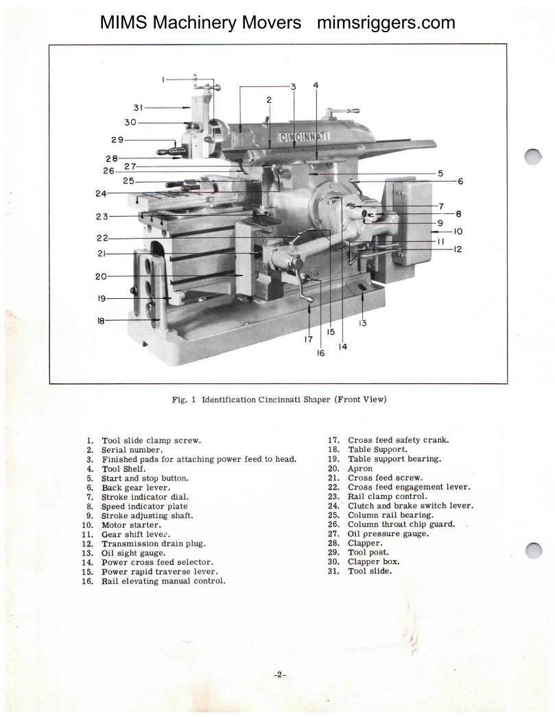
Fig. 1 Identification Cincinnati Shaper (Front View)
1. Tool slide clamp screw.2. Serial number'3. Finished pads for attaching power feed tO head.4. Tool Shelf.5. Start and stop button.6. Hck gear lever.7. Stroke indicator dial.8. Speed indicator plate9. Stroke adjusting sha£t-
10. Motor starter.ll. Gear shift love...12. Transmission drain plug.13. Oil sight gauge.14. Power cross feed selector.15. Power rapid tea.verse lever.16. Rail elevating manual control'
-2-
17. Cross feed safety cranlL18. Table Support.19. Table support bearing.20. Apron21. Cross feed screw.22. Cross feed engagement lever.23. Rail clamp control.24. Clutcl| and brake switch lever.25. Column rail bearing.26. ColuI]m throat Chip gllard.27. Oil pressure ga`lge.28. Clapper.29. Tool post.30. Clapper box.31. Tool slide.
ZiR
MIMS Machinery Movers mimsriggers.com
-'
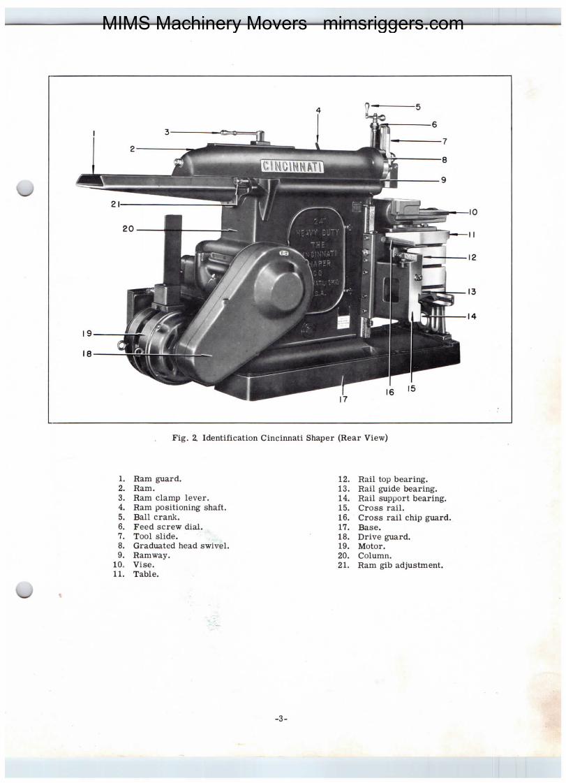
Fig. 2 Identification Cincinnati Shaper (Rear View)
1. Ra.m guard'2. Ram.3. Ram clamp lever.4. Ram positioning shaft.5. Ball crank.6. Feed screw dial.7. Tool slide.8. Graduated head swivel.9. Ra.mwa.y.
loo Vise.ll. Table.
12. Rail top bearing.13. Rail guide bearing.14. Rail support bearing.15. Cross rail.16. Cross rail chip g`lard.17. RIse.18. Drive guard.19. Motor.20. Column.21. Ram gib adjustment.
-3-
MIMS Machinery Movers mimsriggers.com
S|CTIOH I
INSTALLATION
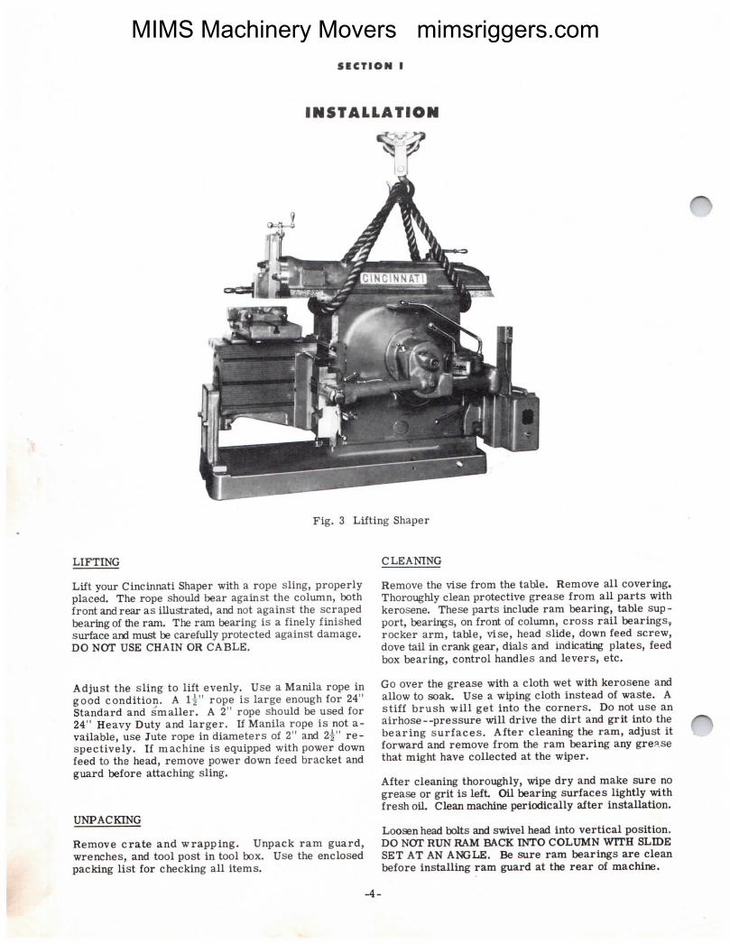
Fig. 3 Lifting Shaper
LIFTING
Lift your Cincinnati Shaper with a rope Slingl Properlyplaced. The rope should bear against the COlumn, hathfront andrear as iuustrated, and not against the scrapedbearingof the ram. The ram bearing is a finely finishedsurface and must be carefully protected against damage.DO NOT USE CHAIN OR CABLE.
Adjust the sling to lift evenly. Use a Manila rope ingood condition. A 1;" rope is large enough for 24"standard and s'maller. A 2" rope should be used for24ll Heavy I)uty and larger. If Manila rope is not a-vaLilable, use Jute rope in diameters Of 2" and 2i" re-spectively. If machine is equipped with POWer downfeed to the head, remove power down feed I)racket andguard before attaching sling.
UNPACKING
Remove crate and wrapping. Unpack ram guard,wrenches, and tool post in tool box. Use the enclosedpacking list for checking all items.
4-
aLEANING
Remove the vise from the table. Remove all covering.Thoroughly clean protective grease from an Parts Withkerosene. These parts include ram bearing} table Sup-port, bearings, on frolut of COl`lmn, Cross I.ail bearings9rocker arm, table, vise, head slide, down feed screw,dove tall in crank gear, dials a-nd indicating Plates, feedbox bear.ingJ COntrOl handles and levers, etC.
Go over the grease With a Cloth Wet With kerosene andallow to soak. Use a wftying cloth instead Of Waste. Astiff brush will get into the corners. Do not use anairhose--pressure will drive the dirt and grit into thebearing SUI.faces. After cleaning the ram, adjust itforward and remove from the ram bearing any greasethat might have collected at the wiper.
After cleaning thoroughly) wipe dry a.nd make Sure nOgrease or grit is left. Cm bearing surfaces lightly withfresh oil. clean machine periodically after installation.
IJOOsenhead tolls and Swivel head into vertical positionoDO NOT RtJN RAM EIACK nITO CO1'UMN "ITH SLIDESET AT AN A)RELE. Be sore ram bearings are Cleanbefore installing ra.m guard at the rear of machine.
Ziill
ZiiE
MIMS Machinery Movers mimsriggers.com

FOUNDATION
E=
Fig. 4 Leveling Sharer
Remove skids and place machine on foundation. A solidconcrete foundation is desirable, but if not practicable,the Shaper may be set on a solid wcod floor and heldwith lag screws. Foundation plans are furnished witheach Shaper, showing the space required and locationof foundation bolts.
LEVELING
Level the machine with a precision level placed on topof the table and column as shown in Fig. 4. Alwayswipe both level and leveling surface clean. Level thema.chimewiththe level crosswise to the table and length-wise on the column. Be sure rail is securely clampedduring this operation.
The base is provided with three bearing points for easyleveling. The tiro front points coincide with the founda-tion bolt holes. The back point is halfway between therear foundation bolt holes. Put flat steel shims at thethree points as requiredto bring the Sha,per level withina thousandth of an inch per foot. After the machine islevel, grout under the base.
UNIVERSAL SIIAPERS VITH TABI,I SUPPORT
On universal machines equipped with an outboard tablesupport, indicate the support guide bar before packingat the corners of the base. The indicator should beclamped to the front of the table. Table bolts shouldbe drawn tight and rail securely clamped. The sup-port g`lide bar should be indicated the full length of therail. The support guide should be parallel with thetop of the rail within.001" perft. Packunder the
corners as required, to make the support level for thefull length. After machine is level,grout under the -base.
After three months of operation go over the machineand draw up screws holding the transmission cover,the rapid traverse arm, and the ram guard. After sixmonths of operation, recheck your machine for level.
OILING
Before starting the Shaper, clean return basin. Returnbasin is accessible through column door.
Fill gear transmission chamber with a high grade, non-foaming machine oil (Viscosity 220 seconds at 100 de-grees F.) according to instruction No. 1I Fig. 5.
Fill the return basin according to instruction No. 3,Fig.5.
Oil should not be below sight gauge in the base whenShaper is stopped.
Check the motor lubrication.
For complete instruction, see Fig. 5 and Oiling Dia-gram, Fig. 7.
CHANGING OIL
Change oil 30 days after installation, thereafter onceevery 12 months. \men changing oil, clean ring mag-net and wipe out return basin and main reservoir witha cloth. Do not use waste.
-5-
MIMS Machinery Movers mimsriggers.com
S|CTl®II II
LuBRICATIO|I
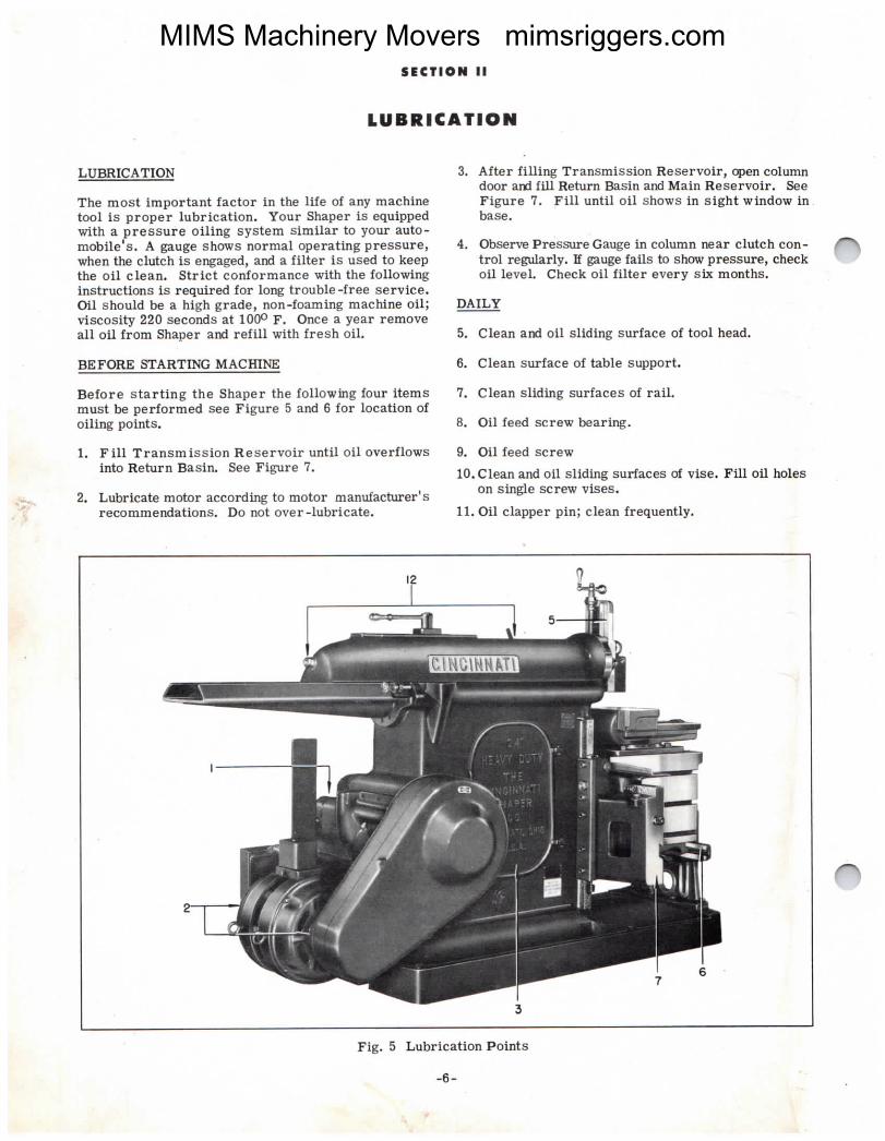
LUBRICATION
The most important factor in the life of any machinetool is proper lubrication. Your Shaper is equipped
¥ob#ePSTefsuirlS::#,ssy£t=isim#¥,intog#:auto*wwhen the clutch is engaged, and a filteI. iS used to keepthe off clean. strict conformance with the followinginstructions is required for long trouble-free service.owl should be a high grade, non-foaming machine oil;viscosity 220 seconds at 100O F. Once a year removeall oil from Shaper and refill with fresh oil.
BEFORE STARTnro MACIIINII
Before starting the Shaper the following four itemsmust be performed see Figure 5 and 6 for location ofoiling points.
1. Pill Transmission Reservoir until oil OVerflowsinto Return Basin. See Figure 7.
2. Lubricate motor according to motor manufacturerlSrecommendations. Do not over-lubricate.
3. After filling Transmission Reservoir, cpen columndoor and fill Ret\lm Basin and Main FLeservoir. SeeFigure 7. Fill until oil shows in sight window inbase|
4. ObservePressureGauge in column near clutch con- ^trol regularly. If gauge fa.ils to show pressure, checkoil level. Check oil filter every sk months.
DAILY
5. Clean and oil sliding surface of tool head.
6. Clean surface of table support.
7. Clean sliding surfaces of rail.
8. Oil feed screw bearing.
9. Oil feed screw
10.Clea.n and oil sliding surfaces of vise. Fill oil holeson single screw vises.
ll. Oil clapper pin; clean frequently.
Fig. 5 Lubrication Points
-6-
MIMS Machinery Movers mimsriggers.com

WEEKLY
12. Fill oil hole at rear of ram and two oil holes nearram adjustment shaft.
13. Oil ram adjusting screw through opening in ram.
14. Oil speed change lever bearings.
l5. Oil crank clutch.
MONTHLY
16. Remove plug and add oil to feed hex.
NorE
17. Do not allow oil level to fall below sight ga-use whenShaper is stopped.
u
Fig. 7 Oiling Diagram
Fig. 6 Lubrication Points
-7-
MIMS Machinery Movers mimsriggers.com
S|CTIOII Ill
OPERATION
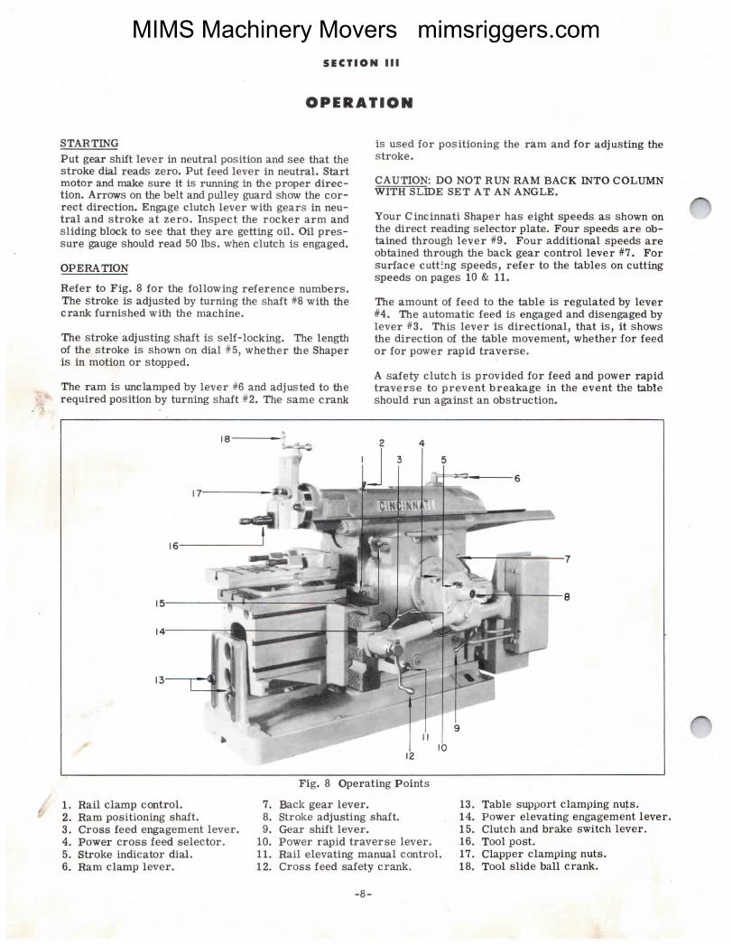
STARTINGPut gear shift lever in neutral position and see that thestroke dial reads zero. Put feed lever in neutral. Startmotor and malre sure it is running in the proper direc-tion. Arrows on the belt and pulley guard show the cor-rect direction. Engage clutch lever with gears in neu-tral and stroke at zero. Inspect the rocker. arm andsliding block to see that they a.re getting oil. oil pres-sure gauge should lea.d 50 1bs. when clutch is engaged.
OPERATION
Refer to Fig. 8 for the following reference numbers.The stroke is adjusted by turning the shaft #8 with thecrank furnished with the machine.
The stroke adjusting shaft is self-locking. The lengthof the stroke is shown on dial #5, whether the Shaperis in motion or stopped.
The ram is unchmped by lever #6 and adjusted to therequired position by turning shaft #2. The same crank
is used for positioning the ram and for adjusting thestroke.
CAUTION: DO NOT RUN RAM BACK INTO COLtJMNWITH SLIDE SET AT AN ANGLE.
Your. Cincinnati Shaper has eight speeds as shown onthe direct reading selector plate. Four speeds are ob-tained through lever #9. Four additional speeds areobtained through the back gear control lever #7. Forsurface cutting speeds, refer to the tables on cuttingspeeds on pages 10 & ll.
The amount of feed to the table is regulated by lever#4. The automatic feed is engaged and disenga.ged bylever #3. This lever is directional, that is, it showsthe direction of the table movement, whether for feedor for power rapid traverse.
A safety clutch is provided for feed and power rapidtraverse to prevent breakage in the event the tableshould run against an obstruction.
" i Rail clamp control.Ram positioning shaft.
3. Cross feed engagement lever.4. Power cross feed selector.5. Stroke indicator dial.6. Ram clamp lever.
Fig. 8 Opera.ting Points
7. RIck gear lever.8. Stroke adjusting shaft.9. Gear shift lever.
10. Power rapid traverse lever.ll. Rail elevating manual control.|2. Cross feed safety crank.
-8-
13. Table support clamping nuts.14. Power elevating engagement lever.15. Clutch and brake s"ritch lever.16. Tool post.17. Clapper clamping nuts.18. Tool slide ball crank.
ZiEI
MIMS Machinery Movers mimsriggers.com
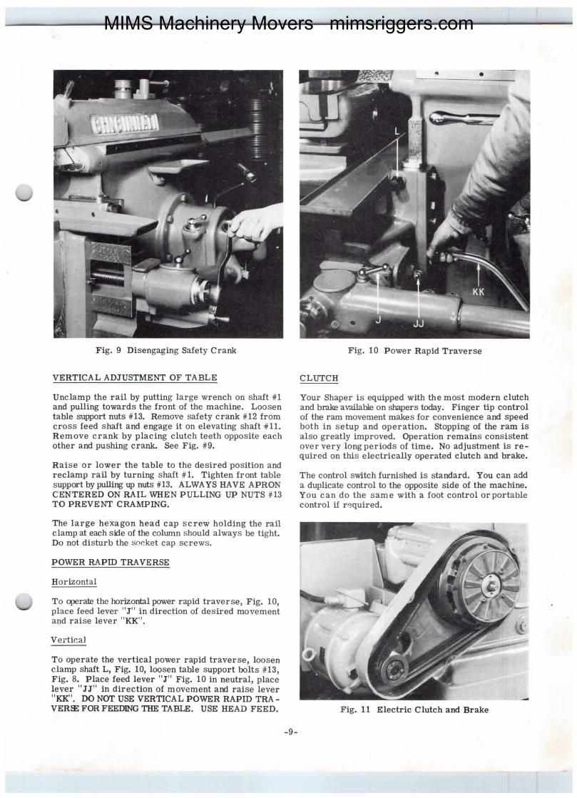
Fig' 9 Disengaging Safety Crank
VERTICAL ADJUSTMEnIT OF TABLE
Unclamp the rail by putting large wrench on shalt #1and pulling tovraI.dS the front Of the machine. Loosentable s`pport nuts #13. Remove safety crank #l2 fromcross feed shaft and engage it on elevating shaft #11.Remove crank by placing clutch teeth opposite eachother and pushing crank. See Fig. #9.
Raise or lower the table to the desired position andreclamp rail by turning shaft #1. Tighten front tablesupport by pulling up mats #13. ALWAYS HAVE APRONCENTEREI) ON RAIL V"EN PUI.LING UP NUTS #13TO PREVE|IT CRAMPING.
The large hexa.gon head cap screw holding the railclamp at each sfle of the col\rmn should always be tight.Do not disturb the socket cap screws.
POWER RAPID TRAVERSE
Horizontal
u To cperate the horizolutal power rapid traverse, Fig. |0,place feed lever "I" in direction of desired movementand raise lever "KK".
Vertical
To operate the vertical power rapid traverse, loosenclamp shaft I, Fig. 10, loosen table support bolts #13,Fig. 8. Place feed level. "I" Fig. 10 in neutral, placelever "JJ" in direction of movement and raise lever"RIrl. DO Nor USE VERTICAL POVnIR RAPID TRA-
VERSE FORFEEImro TIIE TABIJE. USE HEAD FEED.
-9-
CLurCH
Fig. 10 Power Rapid Traverse
Your Shaper is equipped with the most modern clutchand brake available On ShaperS today. Finger tip controlof the ram movement makes for convenience and speedboth in setup and operation. Stopping of the ram isalso greatly improved. Ctoeration remains consistentover very longpeI.iOdS Of time. No adjustment is re-quired on this electrically operated clutch and brake.
The control switch furnished is standard. You can adda duplicate control to the opposite side of the machine.You can do the same with a foot control orportablecontrol if required.
Fig. ll Electric Clutch and Brake
MIMS Machinery Movers mimsriggers.com
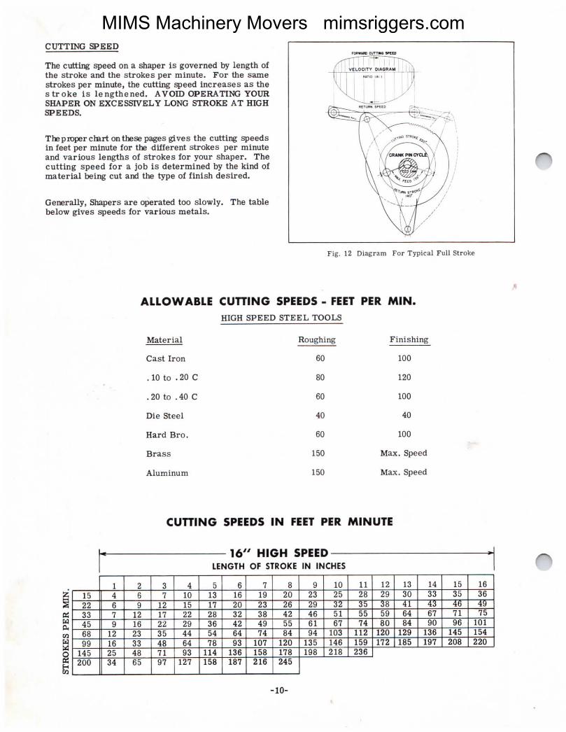
CUTTING SPEED
The c`rfuing speed on a shaper is governed by length ofthe strcke and the strokes per minute. FoI. the SaJnestrokes per minute, the cutting speed increases as thestI.Oke iS lengthened. AVOID OPERATING YOURSIIAPER ON EXCESSIVEI.Y LONG STROKE AT IIIGHSPEEDS.
Theproperchart onthese pages gives the cutting SPeedSin feet per minute for the.different strckeS Per minuteand various lengths of strokes for your shaper. Thecutting speed for a job is determined by the kind ofmaterial being cut and the type of finlsh desired.
Genera||yJ Shapers are operated too slowly. The tablebelow gives speeds for various metals.
Ei`
Fig. 12 Diagram For Typical Full Stroke
ALLOWABLE CUTTING SPEEDS _ FEET PER JV\IN.
HIGH SPEED STEEL Tool.S
mteria.I
Cast Iron
.loco.20C
.20to.40C
Die Steel
Hard Pro.
Brass
A\uminum
Ftoughing
60
80
60
40
60
150
150
Finishins
loo
120
100
4O
100
Max. Speed
Max. Speed
CUTTING SPEEDS IN FEET PER WLINuTE
l6,, HIOH SPEEDLENOTII OF STROKE IN INCHES
1 2 3 4 5 6 7 8 9 10 ll 12 13 14 15 16
15 4 6 7 10 13 l6 19 20 23 25 28 29 30 33 35 36
22 6 9 12 15 17 20 23 26 29 3Z 35 38 41 . . I .
33 7 12 17 22 28 32 38 42 46 51 55 59 64 67 71 75
45 9 16 22 29 36 42 49 55 61 67 74 80 84 90 96 101
68 12 23 35 44 54 64 74 84 94 103 |12 120 129 136 145 154
99 l6 33 48 64 78 93 107 120 135 146 159 172 185 197 208 220145 25 48 71 93 114 136 158 178 198 218 236
200 34 65 97 127 158 187 216 245
-|0-
ZiE[
MIMS Machinery Movers mimsriggers.com

1 2 3 4 5 6 7 8 9 |0 1| |2 13 14 |5 |6 17 18 19 20|2 3 4 6 8 9 10 13 15 16 |8 zO 21 Z3 Z4 Zt) Z2'/ Z8 ilU tl1 j£|7 4 6 8 ll 13 |6 18 21 23 25 28 3O 32 34 36 38 40 42 44 4626 5 8 13 17 20 24 28 32 35 39 42 46 49 52 55 58 61 64 67 70
36 6 |2 17 23 28 34 39 44 49 54 59 63 68 72 77 81 85 90 93 97
54 9 |8 26 34 43 50 58 66 73 81 88 95 102 108 115 121 128 133 140 146
77 |3 25 37 49 61 72 83 94 105 115 l25 |35 145 154 |64 172
|15 19 37 56 73 91 108 124 |40 156 |7Z l88 202157 26 5| 76 loo 127 147 170 192 214
1 2 3 4 5 6 7 8 9 |0 ll 12 l3 14 |5 16 17 18 19 201| 3 4 5 7 9 1| 13 14 16 17 l9 20 2| 23 24 25 26 27 28 .
15 4 6 8 10 |2 14 |6 18 2O 22 24 26 28 30 32 34 35 37 39 4023 5 8 |2 |5 |9 22 26 29 32 35 38 4| 44 46 49 52 55 57 60 6231 6 ll |5 20 25 29 34 38 42 46 51 55 58 62 66 70 73 76 80 8347 8 16 23 30 37 44 5| 58 65 71 77 83 89 94 loo loo 112 116 121 |2668 ll 23 33 44 54 64 74 83 93 101 110 119 128 136 144 152 |61 168
100 |7 33 49 64 79 94 109 123 137 150 163|38 23 45 67 88 log 129 |49 169
2 3 4 5 6 7 8 9 10 ll 12 |3 |4 15 16 17 18 20 22 241U 3 b I/ 9 10 ll 13 1b |6 l7 18 l9 20 2| 22 23 Zb z7 29 32|4 5 7 9 ll |3 |5 17 19 2| 23 24 26 28 30 3Z 33 35 39 42 452| 7 |0 13 16 19 22 25 28 31 34 37 40 43 46 48 5| 53 58 62 6729 1O |4 19 23 27 32 36 40 44 48 51 55 59 63 67 70 73 79 86 9244 15 22 28 35 4| 47 54 - 61 67 72 77 83 89 95 101 106 lil |Z1 131 14064 2| 3| 41 51 60 70 79 88 97 log 113 |21 129 |38 147 154 |6194 30 45 60 74 88 1O2 116 129 142 154 165
129 42 62 82 101 leo |30 |40 159
2 3 4 5 6 7 fl 9 10 ll |2 13 14 |6 |8 20 29- 24 2fl 289 3 4 5 7 8 9 ll 12 13 15 16 17 |8 21 23 25 27 29 3| 33
13 5 7 8 10 |2 14 |6 |8 20 2| 23 25 27 30 34 37 40 43 46 4920 7 |0 13 |6 19 22 25 28 3| 33 36 39 42 47 52 57 6| 66 7O 7427 9 13 17 21 25 29 33 37 41 45 48 52 56 6| 69 77 83 89 95 1014| |3 20 26 32 38 44 50 56 62 68 73 79. 84 94 log ||5 |25 |35 144 15259 |9 28 37 46 55 64 73 82 90 98 loo 114 122 138 152 16687 28 41 54 67 80 . 106 119 132 144 |56 |68
119 39 57 75 93 111 129 147 165
? 4 I A 1fl 12 14 . 1R ?fl ?? 24 . 2R 3n R2 .
8 3 5 8 |0 12 |4 16 18 20 23 25 27 29 31 33 35 37 39ll 5 7 ll |4 1B 2O 24 27 30 33 35 37 39 41 43 45 48 50|7 6 |1 |6 2| 26 3| 36 4O 44 48 52 56 60 64 68 71 775 7823 8 15 22 29 36 43 49. 55 6| 67 72 77 82 87 92 96 1O1 log35 12 23 34 45 55 65 74 83 92 10| 110 18 |25 133 |40 147 153 15950 17 32 48 64 78 92 106 Ilo 131 145 157 |6874 25 49 72 95 116 |36 156
|02 33 65 97 129 160
-ll-
i
E=;
Ei:
i;
MIMS Machinery Movers mimsriggers.com
|JNIVERSAL TABLES
qF
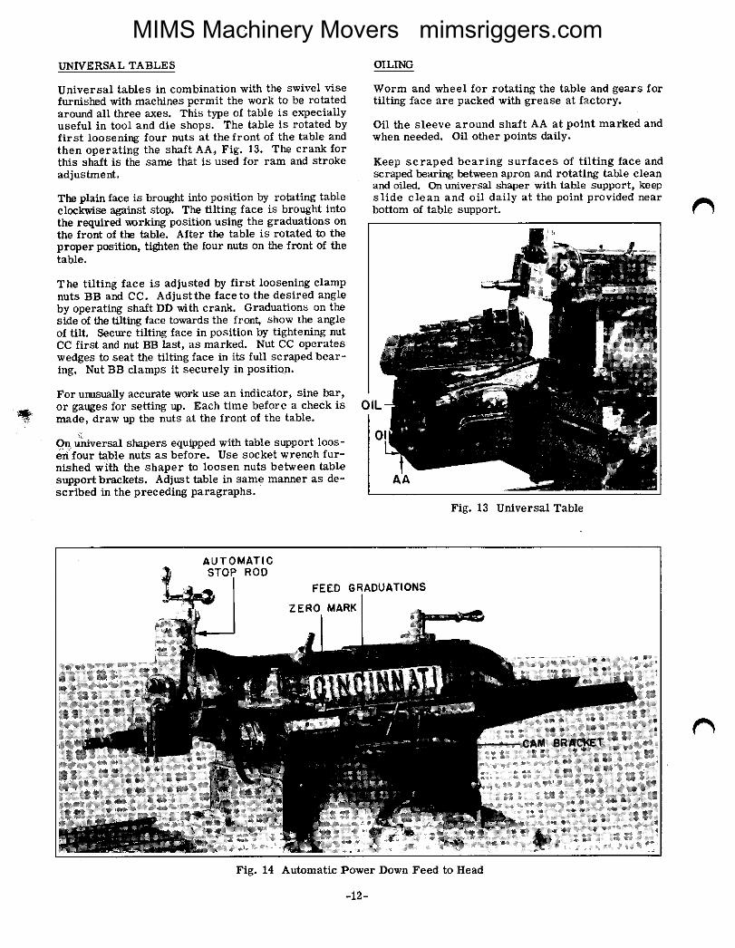
universal tables in combination with the swivel visefurIliShed With machines Permit the Work tO be rotatedaround all three axes. This type of table iS expeCiallyuseful in tool and die shops. The table is rotated byfirst loosening four nuts at the front of the table andthen operating the shaft AA; Fig. l3. The crank forthis Shalt iS the Same that iS used for ram and StrC)kezLdjuStment®
The plain face is brought into POSitiOn by rotating tableclactwrise against stop. The tilting face is brought intothe required verking position using the graduations onthe front of the table. After the table is rotated tO theproper position, tig`ten the four nuts on the front of thetable.
The tilting face is adjusted by first loosening Clampnuts BB and CC. Adjustthe faceto the desired angleby operating shaft DD with crank. Graduations on theside of the tilting face tOunrdS the front, Show the angleof tilt. secure tilting face in position by tightening nutcc first and nut BB last, aS marked. Nut CC operateswedges to seat the tilting face in its full scraped bear-ing. Nut BB clamps it securely in position.
For uIluS`lal|y accurate Work use an indicator, Sine bar,or gauges for setting up. Each time before a check iSmade) draw up the nuts at the front of the ta-ble.
on urirversal shapers equipped with table support loos-e`nlour table nuts as before. use socket wrench fur-nished with the shaper to loosen nuts between tablesupportbI.ackets. Adjust table in same manneI. aS de-scribed in the preceding paragraphs.
OILING
Worm and wheel for rotating the ta,ble and gears fortilting face are packed with grease at factory.
Oil the sleeve around shaft AA atpoint marked andwhen needed. Oil other points daily.
Keep scraped bearing surfaces of tilting face andscraped bearing bet`veen apron and rotating table cleanand oiled. Cia universal sharer with table support, keeI3slide clean and oil daily at the point provided nearbottom of table support.
Fig. 13 Universal Table
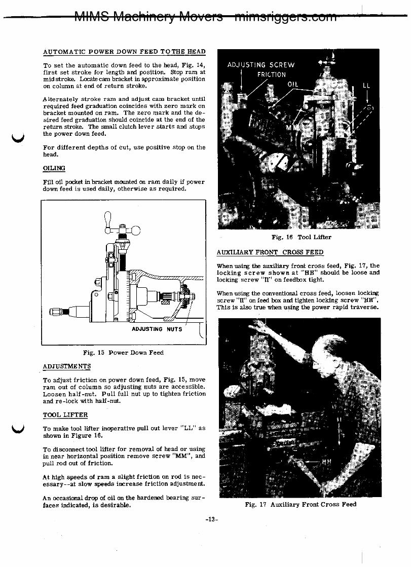
Fig. 14 Automatic Power Down Feed to Head
-12-
MIMS Machinery Movers mimsriggers.com
AUTOMATIC POWER DOWN FEED TOTHE IIEAD
u
U
To set the automatic down feed to the head, Fig. 14lfirst set stroke for length and posltlon. Stop ram atmid stroke. IJOCate Cam bracket in approximate POSltiOnon column at end of return stroke.
Alternately stroke ram and adjust cam bracket untilrequired feed graduation coincides with zero mark onbracket mounted on ram' The zero mark and the de-sired feed graduation sl`ould coincide at the end of thereturn stroke. The small clutch lever starts and stopsthe power down feed.
For different depths of cut, use positive stop on thehead.
OILING
Fill oil pocket in blanket mCunted On ram daily if Powerdovm feed is used daily, otherwise as requiI.ed.
Fig. 15 Power Down Feed
ADJUS"ENTS
To adjust friction on power down feed, Fig. l5, moveram out of column so adjusting nuts are accessible.Loosen half-nut. Pull full nut up to tighten frictionand re-lock vdth half-nut.
TcoL LIFTER
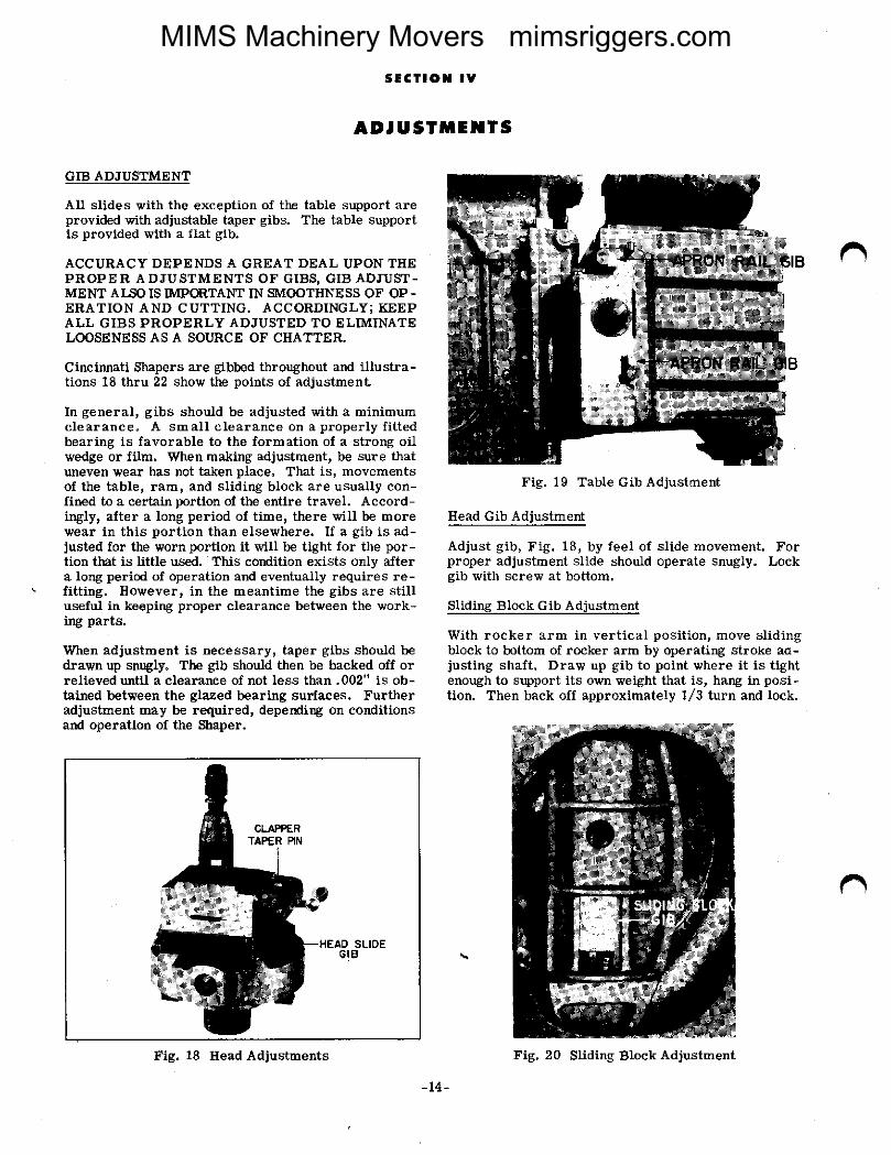
Fig. 16 Tool Litter
AtJInLIARY FROrIT CROSS FEED
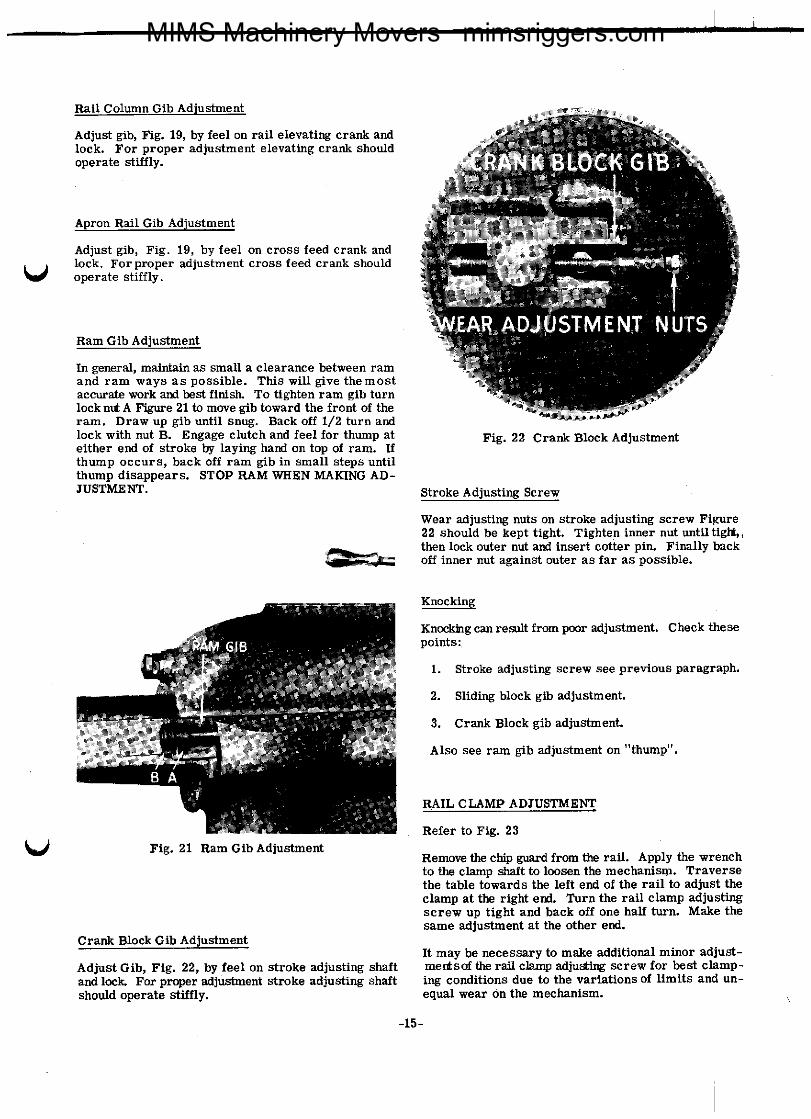
"then using the auxiliary front cI.ass feed, Fig. 17, thelocking screw shown at "HH" should be loose andlc)cking screw "rI" on feedbox tight.
\Then using the conventional cross feed, loosen lockingscrew "H" on feed box and tighten locking screw "HH".This is also true when using the pow7er rapid traverse.
To make tool litter inoperative Pull out lever l'LL" asShown in Figure 16.
To discormect tool litter for removal Of heed Or usingin near horizontal position remove screw "MM'', andpull rod out of friction.
At high speeds of ram a SlightfrlCtlOn On rod iS nec-essary--at slow apeeds increase friction adjustment.
An occasional drop of oil on the hardened bearing Sur-faces indicated, is desirable.
-13_
Fig. 17 Auxiliary Front Cross Feed
MIMS Machinery Movers mimsriggers.com
S|CTl®H IV
ADJIJSTAAENTS
GIP ADJUSTMENT
All slides with the exception of the table slIPPOrt areprovided with adjustable taller Bibs. The table supportis provided with a flat gib.
ACCURACY DEPENI)S A GREAT DEAL UPON THEPROPER ADJUSTMENTS OF GIPS, GIP ADJUST-MErIT AI,SO IS II\OCRTArIT IN SMOOTHNESS OF OP -ERATION AND CUTTING. ACCORI)INGLY; KEEPA|,L GIBS PROPERLY ADJUSTED TO ELIMINATELOOSENESS AS A SOURCE OF CHATTER.
Cincinnati Shapers are glbbed throughout and illustra-tions 18 thru 22 show the points of adjustment
In general, gibs should be adjusted with a minimumcleaLranCe. A small clearance on a properly fittedbearing is favorable to the forma-tic)n of a stI.Ong Oilwedge or film. "Then malting aLdjuStment, be Sure thZltuneven wear has not taken placea That is) movementsof the table, raml and sliding block a.re usually con-fined to a certain portion of the entire travel. Accord-ingly) after a long period of time, there will be moreweal. in this portion than elsewhere' If a gib is ad-justed for the wo- portion it will be tight for the por-tion that is little used. This condition exists only altera long period of operation and eventually requires re-fitting' However, in the meantime the gibs are stilluseful in keeping proper clearance between the work-ing pflrts.
"then adjustment is necessary] taper gibs should bedraum up snuglyo The gib should then be backed off orrelieved until a clearance of not less than.002" is ob-tained between the glazed bearing surfaces. Furtheradjustment may be required, depending on conditionsand operation of the Shaper-
Fig. 18 Head Adjustments
Fig' 19 Table Gib Adjustment
Head Gib Adj_ustmerd
Adjust gib) Fig. 18, by feel of slide movement. Forproper adjustment slide should operate snugly. Lockgib with screw at bottom.
Sliding Block Gib Adjustment
With rocker arm in vertical position, move slidingblock to bottom of rocker arm by operating stroke ad-justing shaft Draw up gib to point where it is tightenough to support its own weight that is, hang in posi-tion. Then hack off approximately 1/3 turn and lock.
Fig. 20 Slicling Block Adjustment
-14-
r\
MIMS Machinery Movers mimsriggers.com
Rail Column Gib Adinstment
Adjust Bib, Fig. 19, ty feel on rail elevating crank andlock. For proper adjustment elevating crank shouldoperate stiffly.
Apron Rail Gib Ad
u
U
Adjust gib) Fig. 19) by feel on cross feed crank andlock. Forproper adjustment cross feed Crank Shouldoperate stiffly.
Ram Gib Adjustment
In general, maintain as small a clearance between ramand ram ways as possible. This will give themostaccurate work and best finislL To tighten ram Bib turnlocknut A Figure 21 to move gib toward the front of theram. I)raw up gib until s-g. Back off 1/2 turn andlock with nut B. Engage clutch and feel for thump ateither end of stroke by laying hand on top of ram. Ifthump occurs, back off I.am gib in Small Steps untilthump disappears. STOP RAM VI"EN MAKING AD-JUSTMENT.
EE=
Fig. 21 Ram GibAd]ustment
Crank Block Gib Adjustment
Adjust GIL, Fig. 22, by feel on stroke adjusting shaltand lock For proper nd]urfuent stroke adjusting shaftshould operate stiffly.
Fig. 22 CI.auk Block Adjustment
Stroke Adjusting Screw
Wear adjusting nuts on stroke zldjusting screw Fig`lre22 should be kept tight. Tighten inner nut until tiglrtythen lock outer nut and insert cotter pin. Finally backoff i-er nut against outer as far as possible.
Knocking
Knoclchg can result from poor adjustment. Check thesepoints:
1. Stroke adjusting screw see previous PamgraPh.
2. Sliding block Bib adjustment.
3. Crank Block gib adjustment.
Also see ram gib adjustment on "thump".
RAIL CIAMB ADJUSTMErIT
Refer to Fig. 23
Remove the chip guard from the rail. Apply the wrenchto the clalnP Shaft tO loosen the mechanism. Traversethe table towards the left end of the rail to adjust theclamp at the right end. rum the rail clamp adjustingscrew up tight and back off one half turn. Make thesame adjustment at the other end.
It may be necessary to make additional minor adjust-merisof the rail clamp adjusting screw for best clamp-ing conditions due to the variations of limits and un-equal wear on the n`eehol`ism.
-15-
MIMS Machinery Movers mimsriggers.com
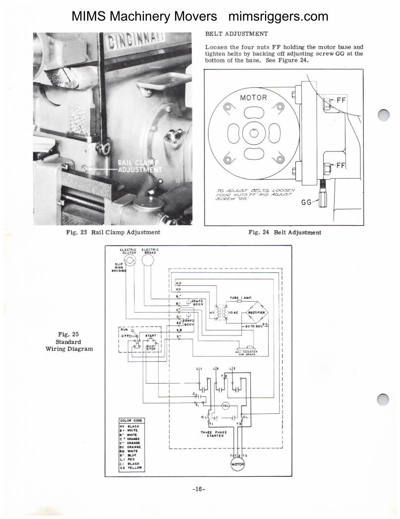
Fig. 23 Rail Clamp Adjustment
Fig' 25Standard
Wiring Diagram
Fig. 24 Belt Adjustment
¬| ECT\lG ¬LEC|l\l¢CLO+C| |R^|E
HV
l|V
I+.1®|II-Cooa. aV
lvl lE"o^c.'en.l"
=t.8!ofI| ®OT® ®OV
I-
HV BL^C*I+ "lttI- "ldOtC-IC_ On-8C ORA|®(|B "lTf|- |utLl l|EDCl |uexc2 1¬L|co
"kte PIAeEa \\*TE R
I
L____________
-16-
MIMS Machinery Movers mimsriggers.com