operation and maintenance manual for hand pumps
TRANSCRIPT
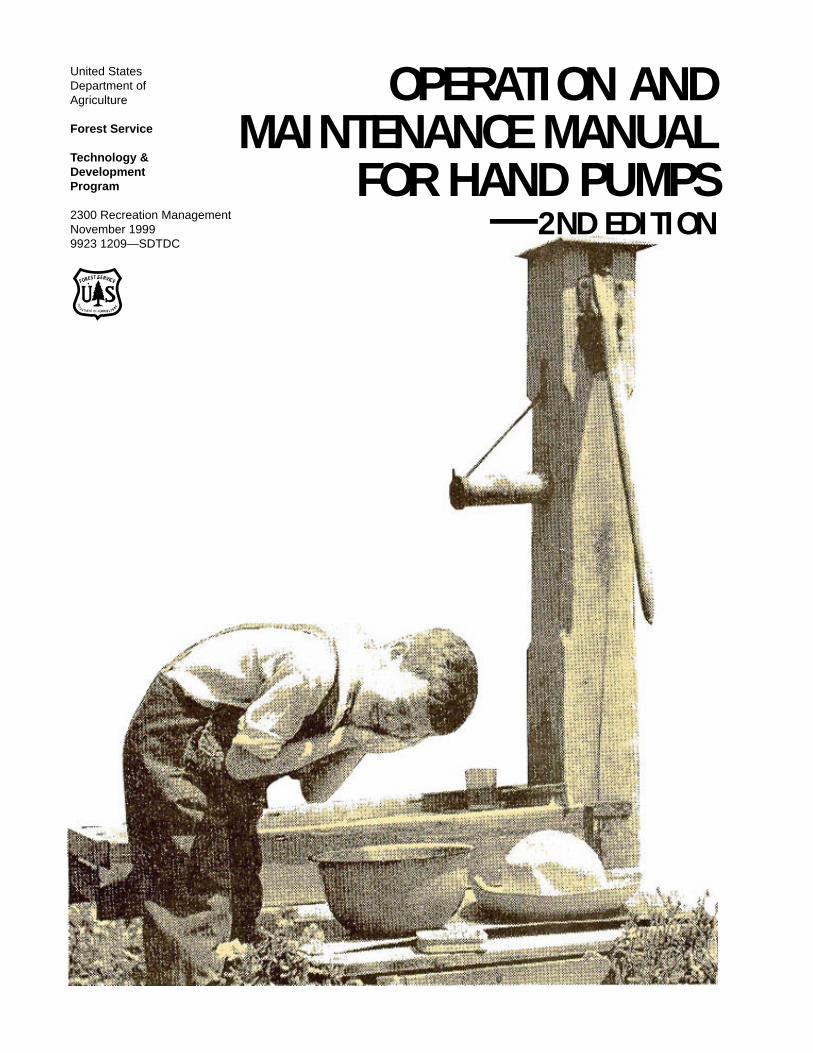
OPERATION ANDMAINTENANCE MANUAL
FOR HAND PUMPS
United StatesDepartment ofAgriculture
Forest Service
Technology &DevelopmentProgram
2300 Recreation ManagementNovember 19999923 1209—SDTDC
FOREST SERVICE
DE
P A RTMENT OF AGR IC U L T U RE
—2ND EDITION
ACKNOWLEDGMENTSRecognition is given to the Forest Service Northern Region Environ-mental Engineering for their assistance in the preparation of thissecond edition. Special thanks are extended to Beverly Young, TomKeyes and Don Senn for their contributions, advice and support duringthe preparation of this manual.
OPERATION ANDMAINTENANCE MANUAL
FOR HAND PUMPS—2ND EDITION
November 1999
Fred Cammack, P.E.Senior Mechanical Engineer
USDA Forest ServiceTechnology & Development Center
San Dimas, California
In Cooperation WithEnvironmental Engineering
Forest Service Northern Region
Information contained in this document has been developed for the guidance ofemployees of the Forest Service, USDA, its contractors, and cooperatingFederal and State agencies. The Department of Agriculture assumes no responsibilityfor the interpretation or use of this information by other than its own employees.The use of trade, firm, or corporation names is for the information and convenienceof the reader. Such use does not constitute an official evaluation, conclusion,recommendation, endorsement, or approval of any product or service to theexclusion of others that may be suitable.
The United States Department of Agriculture (USDA) prohibits discrimination inits programs on the basis of race, color, national origin, sex, religion, age,disability, political beliefs, and marital or familial status. (Not all prohibited basesapply to all programs.) Persons with disabilities who require alternative meansfor communication of program information (Braille, large print, audiotape, etc.)should contact the USDA Office of Communications at 202-720-2791 (voice), or800-855-1234 (TDD).
To file a complaint, write the Secretary of Agriculture, U.S. Department ofAgriculture, Washington, DC 20250, or call 1-800-245-6340 (voice), or 800-855-1234 (TDD). USDA is an equal employment opportunity employer.
23
O P E R A T I O N A N D M A I N T E N A N C E M A N U A L F O R H A N D P U M P S
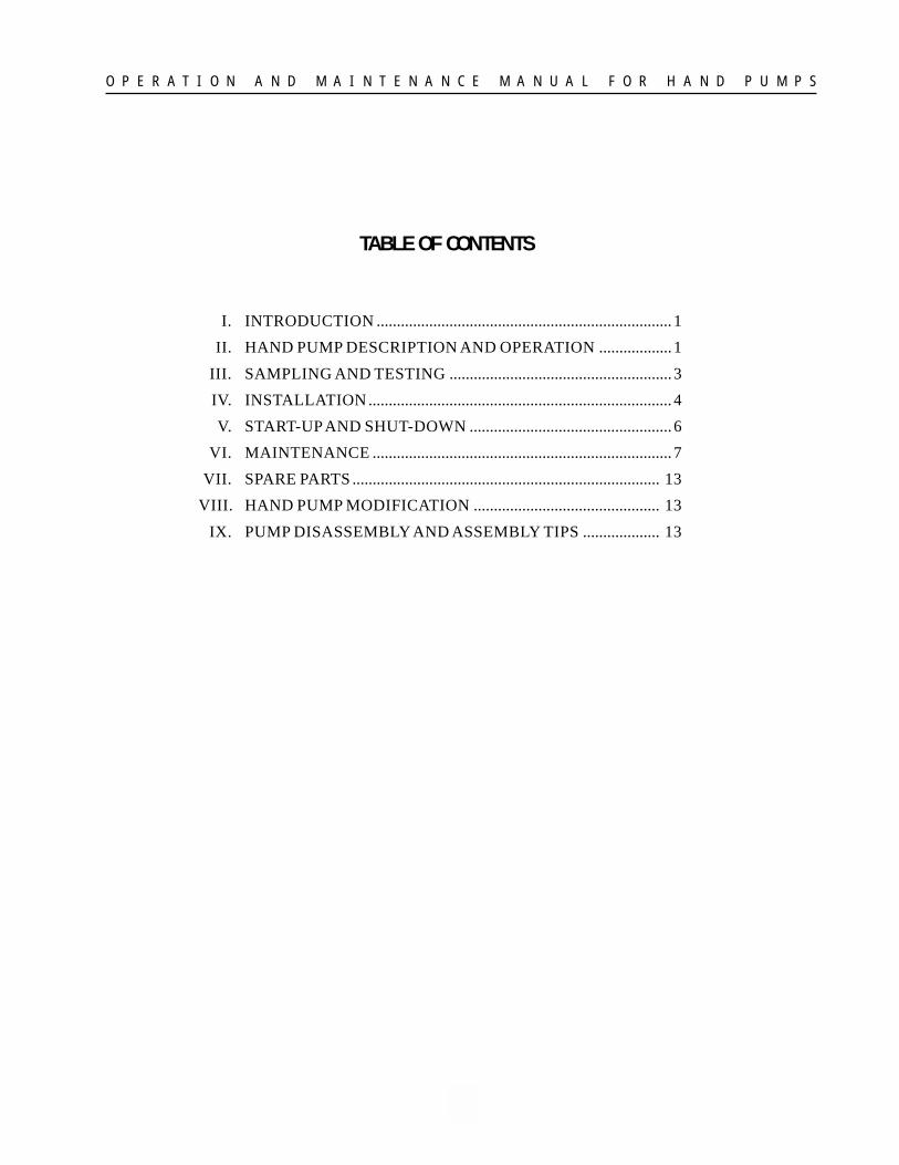
TABLE OF CONTENTS
I. INTRODUCTION ......................................................................... 1
II. HAND PUMP DESCRIPTION AND OPERATION .................. 1
III. SAMPLING AND TESTING ....................................................... 3
IV. INSTALLATION ........................................................................... 4
V. START-UP AND SHUT-DOWN .................................................. 6
VI. MAINTENANCE .......................................................................... 7
VII. SPARE PARTS ............................................................................ 13
VIII. HAND PUMP MODIFICATION .............................................. 13
IX. PUMP DISASSEMBLY AND ASSEMBLY TIPS ................... 13
1
O P E R A T I O N A N D M A I N T E N A N C E M A N U A L F O R H A N D P U M P S
I. INTRODUCTIONThe Northern Region’s 1999 potable water inven-tory showed that there are 188 hand pumps in usein that region. Approximately 60 percent of all thewater systems at recreation sites in the ForestService Northern Region utilize hand pumps. Otherregions also use hand pumps at sites where elec-tricity is not available. The hand pump is likely toremain a common method of withdrawing wellwater at Forest Service campgrounds.
The primary reasons for the popularity of the handpump in the Forest Service are its simple designand its usability at well sites without electricity.Hand pumps also can operate satisfactorily infreezing weather for early and late season use.Generally, the hand pump has proven to be popu-lar with the public. One only has to view thenumber of old red hand pumps that overlooklawns and flower gardens to sense the nostalgiathat is associated with this reminder of the past.
Sanitary surveys on hand pumps in Region Oneidentified some recurring problems at many of theinstallations. Some of these deficiencies wereassociated with the design of the hand pump stands,and some were associated with pump installa-tions, such as, drainage, slabs, etc. The Region’sstandard drawing for the installation of hand pumpswas approved in 1978 based on the data gatheredfrom those sanitary surveys.
The purpose of this manual is to provide informa-tion on the installation and maintenance of wellhand pumps. The manual specifically addressesthe operation and maintenance of Monitor handpumps supplied by Baker Manufacturing Com-pany, Evanston, Wisconsin. The majority of handpumps that are in current use by the Forest Serviceare Monitor pumps. For information on parts avail-ability, pricing and procedures not covered in thismanual contact Baker Manufacturing at (608)882-5100.
It is recommended that copies of this manual bedistributed to all facilities engineers and districtpersonnel responsible for maintaining water sys-tems.
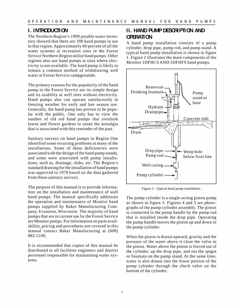
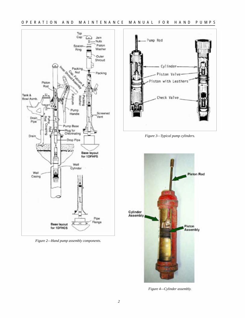
II. HAND PUMP DESCRIPTION ANDOPERATIONA hand pump installation consists of a pumpcylinder, drop pipe, pump rod, and pump stand. Atypical hand pump installation is shown in figure1. Figure 2 illustrates the main components of theMonitor 1DFHCS AND 1DFHFS hand pumps.
Figure 1—Typical hand pump installation.
The pump cylinder is a single-acting piston pumpas shown in figure 3. Figures 4 and 5 are photo-graphs of the pump cylinder assembly. The pistonis connected to the pump handle by the pump rodthat is installed inside the drop pipe. Operatingthe pump handle moves the piston up and down inthe pump cylinder.
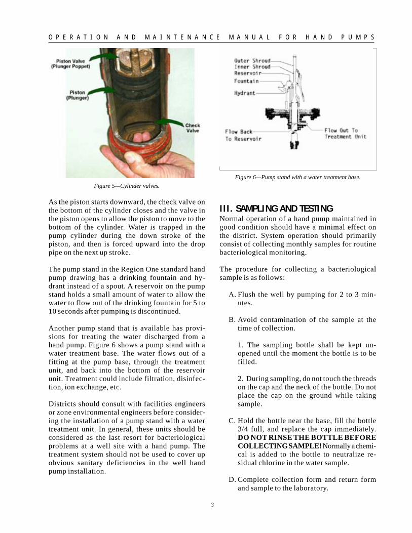
When the piston is drawn upward, gravity and thepressure of the water above it close the valve inthe piston. Water above the piston is forced out ofthe cylinder, up the drop pipe, and out the spigotor fountain on the pump stand. At the same time,water is also drawn into the lower portion of thepump cylinder through the check valve on thebottom of the cylinder.
ReservoirDrinking fountain
HydrantDrainpipe
Drain
Pumpstand orbase
Concrete slab
Weep holebelow frost line
Drop pipePump rod
Well casing
Pump cylinder
2
O P E R A T I O N A N D M A I N T E N A N C E M A N U A L F O R H A N D P U M P S
Figure 4—Cylinder assembly.
Figure 2—Hand pump assembly components.
Figure 3—Typical pump cylinders.
3
O P E R A T I O N A N D M A I N T E N A N C E M A N U A L F O R H A N D P U M P S
Figure 5—Cylinder valves.
As the piston starts downward, the check valve onthe bottom of the cylinder closes and the valve inthe piston opens to allow the piston to move to thebottom of the cylinder. Water is trapped in thepump cylinder during the down stroke of thepiston, and then is forced upward into the droppipe on the next up stroke.
The pump stand in the Region One standard handpump drawing has a drinking fountain and hy-drant instead of a spout. A reservoir on the pumpstand holds a small amount of water to allow thewater to flow out of the drinking fountain for 5 to10 seconds after pumping is discontinued.
Another pump stand that is available has provi-sions for treating the water discharged from ahand pump. Figure 6 shows a pump stand with awater treatment base. The water flows out of afitting at the pump base, through the treatmentunit, and back into the bottom of the reservoirunit. Treatment could include filtration, disinfec-tion, ion exchange, etc.
Districts should consult with facilities engineersor zone environmental engineers before consider-ing the installation of a pump stand with a watertreatment unit. In general, these units should beconsidered as the last resort for bacteriologicalproblems at a well site with a hand pump. Thetreatment system should not be used to cover upobvious sanitary deficiencies in the well handpump installation.
Figure 6—Pump stand with a water treatment base.
III. SAMPLING AND TESTINGNormal operation of a hand pump maintained ingood condition should have a minimal effect onthe district. System operation should primarilyconsist of collecting monthly samples for routinebacteriological monitoring.
The procedure for collecting a bacteriologicalsample is as follows:
A. Flush the well by pumping for 2 to 3 min-utes.
B. Avoid contamination of the sample at thetime of collection.
1. The sampling bottle shall be kept un-opened until the moment the bottle is to befilled.
2. During sampling, do not touch the threadson the cap and the neck of the bottle. Do notplace the cap on the ground while takingsample.
C. Hold the bottle near the base, fill the bottle3/4 full, and replace the cap immediately.DO NOT RINSE THE BOTTLE BEFORECOLLECTING SAMPLE! Normally a chemi-cal is added to the bottle to neutralize re-sidual chlorine in the water sample.
D. Complete collection form and return formand sample to the laboratory.
4
O P E R A T I O N A N D M A I N T E N A N C E M A N U A L F O R H A N D P U M P S
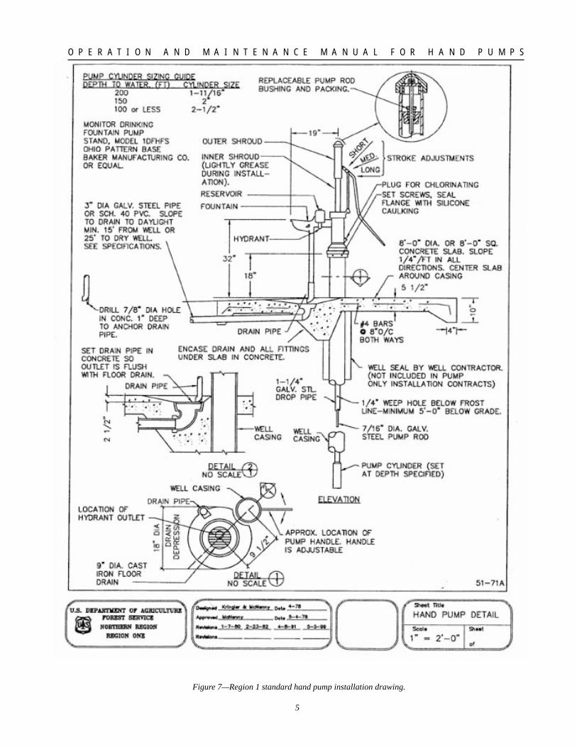
IV. INSTALLATIONFigure 7 is the Region One standard drawing forthe installation of hand pumps. The standard drawinghas been reviewed and approved by the MontanaDepartment of Environmental Quality. All re-gions should have an installation drawing ap-proved by the appropriate regional and state au-thorities. Region One requires that this drawingbe used for the installation of hand pumps on newwells and the rehabilitation of existing hand pumpsites. The appropriate State authority and the Re-gional Environmental Health Engineer must ap-prove any deviations from approved plans at siteswith public water systems. The Regional Envi-ronmental Health Engineer must approve devia-tions from the plans at remaining sites.
The pump model used in the 1978 Region Onestandard drawing was the Monitor 1DFHF pumpstand. Virtually all of the hand pump installationsrehabilitated in Region One prior to 1984 used the1DFHF pump stand.
Baker Manufacturing quit making the 1DFHFpump stand in late 1983. The company offers the1DFHFS pump stand as the replacement for the1DFHF. The Monitor 1DFHFS pump stand isshown in Figure 7. The only difference betweenthe two pump stands is the cap and flat piston baron the 1DFHF pump were replaced with a shroudon the 1DFHFS pump stand.
The following items should be emphasized for theinstallation of hand pumps.
A. Draining excess water away from the con-crete slab is important. During rehabilita-tion of a number of old hand pump installa-tions, several of the wells had developeddeep cavities under the old slabs and downalong the well casings. These cavities wereup to six feet or more in depth. It is likelythat excess water seeped under the slab anddown along the opening next to the wellcasing. A small space is sometimes left be-tween the casing and natural ground whenwells are drilled. Surface water could perco-late down and contaminate the groundwater.Rodents, snakes, etc., could also live in acavity under the slab and contribute to ground-water contamination.
B. The length of the installed pump rod shouldbe such that the piston does not hit the top ofthe cylinder when the pump handle is at thebottom of its travel. The constant poundingcould cause the pump rod to separate at athreaded joint or damage the pump cylinderor piston. About 1/2-inch to 1-inch of theround piston bar (not including threads) onmodel 1DFHF pump stands should be vis-ible above the packing nut when the pistonis resting on the bottom of the pump cylin-der. This will allow the packing to be changedwithout the top of the threaded piston bardropping below the level of the packing nutwithout temporary support. The manufac-turer recommends that equal lengths of droppipe and pump rod should be installed onMonitor pumps. Pump rod is available instandard lengths of 18, 20, and 21 feet,which correspond to the standard lengths ofdifferent types of pipe used for drop pipe.Galvanized steel pipe is normally installedfor the drop pipe. Pump rods can be short-ened by cutting them to the desired lengthand re-threading the cut end.
C. The weep hole in the drop pipe should bedrilled instead of torch cut to ensure that aclean hole of proper size is made. The weephole can be checked by operating the handpump until water is discharged from thespout. Let the pump stand idle for 50 to 60seconds and then operate the pump again. Ifwater is discharged from the spout withinthe first one or two up-and-down motions ofthe pump handle, the weep hole is pluggedor not large enough.
D. The pump cylinder should be installed be-low the lowest anticipated level of the watertable to eliminate any pollution hazard asso-ciated with priming the pump with non-potable water.
E. Substituting another brand of pump for theMonitor pump stand shown on the drawingshould not be done unless it is known thatthe two pump stands are equivalent. Dis-tricts should consult with facilities engi-neers or zone environmental engineers be-fore purchasing another brand of hand pump.
5
O P E R A T I O N A N D M A I N T E N A N C E M A N U A L F O R H A N D P U M P S
Figure 7—Region 1 standard hand pump installation drawing.
6
O P E R A T I O N A N D M A I N T E N A N C E M A N U A L F O R H A N D P U M P S
F. The hydrant outlet should be located overthe floor drain.
G. In older installations there is an access port(threaded plug) near the top of the wellcasing. Current models have a threaded plugin the pump base allowing:
1. The well to be disinfected without re-moving the pump.
2. The access port is convenient for measur-ing the water level in the well.
V. START-UP AND SHUT-DOWNA condition survey should be performed on eachhand pump installation in the spring before sys-tem start-up and after the system is shut-down inthe fall. Year-round sites that have hand pumpsshould have a condition survey performed at leastonce a year.
A condition survey is simply a physical inspectionof the hand pump. Typical items to be checked ona condition survey are summarized below.
A. Drainage system should be open and func-tioning properly.
B. Concrete slab should not be cracked andburrows under this slab should be filled.
C. Nuts and bolts tight, gaskets intact at water-tight joints.
D Pump stand and major components not crackedor broken.
E. Packing nut and packing checked for wear;hole in packing nut not worn oblong; pack-ing nut not bottomed out because packingworn out. Check upper piston guide on model1DFHF and 1DFHC pumps.
F. Weep hole open.
A condition survey performed when the system isshut-down in the fall is useful in identifying main-tenance items that should be corrected before thesystem is opened for the next season. Materialscan be ordered during the winter to be on hand for
installation early next season. A condition surveybefore system start-up can determine if any addi-tional damage has occurred during the winterfrom vandalism, frost action, etc.
Start-up
A. Perform condition survey.
B. Complete necessary maintenance repairs.
C. Install pump handle.
D. Loosen and readjust packing nuts on Moni-tor 1DFHC and 1DFHF pump stands. Addpacking if necessary.
E. Flush well by pumping until discharge isclear of rust, sediment, etc.
F. Sample water for bacteriological testing.Remove pump handle.
G. Install the pump handle. If bacteriologicaltest is satisfactory, the water system may beopened for use.
H. Chlorinate the well and let it stand for aminimum of four hours. If the bacteriologi-cal test is unsatisfactory, repeat all stepsbeginning with Step E. Flush the well untilthe free chlorine residual drops below 0.5mg/L.
I. Request a sanitary survey from the Forestfacilities engineer if subsequent bacterio-logical samples continue to show contami-nation.
Shut-down
A. Perform condition survey.
B. Tighten packing nut on Monitor 1DFHC and1DFHF pump stands so packing forms awatertight seal while the hand pump is shutdown for the season. Tighten packing nutuntil piston bar cannot be moved.
C. Remove pump handle.
7
O P E R A T I O N A N D M A I N T E N A N C E M A N U A L F O R H A N D P U M P S
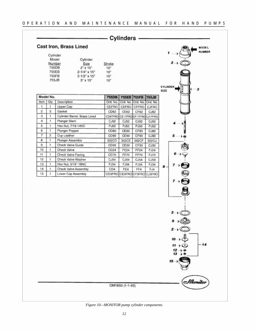
VI. MAINTENANCELike any other piece of machinery, hand pumpshave maintenance requirements. Common main-tenance procedures for hand pumps are describedin the following paragraphs. Numbers in paren-theses refer to part numbers of typical Monitorpumps shown in figures 8 and 9. The parts nomen-clature of a Monitor pump cylinder is shown infigure 10. Figure 10 shows the components of acast iron cylinder with a brass liner. Currently, allcylinder components are made of brass and thecast iron cylinders are no longer available fromthe manufacturer. Figure 10 is still useful becauseit depicts the majority of cylinders that will needservice within the next ten years.
Drainage System—The drainpipe should be cleanedas needed to keep excess water draining awayfrom the slab area.
Slab—The concrete slab should be replaced ifopen cracks develop in the slab. Hairline cracks ina steel reinforced slab generally should not beconsidered a threat to the sanitary quality of thewell water. The ground level around the slabshould be maintained at the elevation of the slabso surface water does not collect in low spots orform channels under the slab. Maintaining theground level at slab elevation should reduce thechances of rodents burrowing under the slab.
Pump Stand—Nuts and bolts on the stand shouldbe tight. Gaskets on the reservoir cover and thetank-to-base connection should be maintained ina watertight condition. Cracked components suchas the pump base, reservoir cover, etc., should bereplaced as soon as possible to protect the sanitaryquality of the water.
Sealed Pump Flanges—Many older model pumpstands had flanged pump bases that bolted di-rectly to the concrete pad or to a sealed pumpflange mounted on the top of the casing. Theflange gaskets in these connections must be main-tained to provide a watertight seal and preventcontamination of the well. Mounting bolts mustbe tight and the flange gaskets must be in goodcondition.
Disinfection of the Well—The well should bedisinfected whenever the pump stand is raised orremoved for maintenance. The procedure is de-scribed below.
1. Wash the exterior surface of the drop pipeand pump cylinder with a 100 mg/L chlorinesolution as they are lowered into the well.
NOTE: 1/6 cup of 5-1/4 percent household bleachper five gallons of water is approximately a 100mg/L chlorine solution.
2. Pour chlorine solution into well just beforeinstalling pump cylinder and drop pipe as-sembly. Chlorine solution shall be solutionof one cup of 5-1/4 percent chlorine bleachor three 7 gram Olin HTH tablets diluted in5 gallons of clear water into the well foreach 20 feet of standing water. Dispersechlorine evenly through the well by pouringchlorine solution through a hose or pipe thatis moved up or down in the well wheneverpossible.
3. After installation of the hand pump is com-pleted, operate the hand pump until the dis-tinct odor of chlorine is detected in thedischarge.
4. Remove the pump handle and allow thechlorine solution to remain in the well for aminimum of 4 hours, preferably overnight.
5. After disinfecting, flush the well until thefree chlorine residual is measured to be lessthan 0.5 mg/L. Take water sample for bacte-riological testing at a certified laboratory.Remove pump handle.
6. If the bacteriological test is satisfactory, thewater system may be opened for use and thepump handle reinstalled.
Well Cleaning or Flushing—Some wells are notadequately cleaned at the low pumping rate ofhand pumps. Accumulations of sediment, rustparticles, etc., eventually may affect the physicalquality of the well water. At some sites, periodiccleaning of the well can be beneficial. Districtsshould consult with facilities engineers or zoneenvironmental engineers on specific installations.Portable pump jacks with gasoline engines areavailable to mechanically operate the pump cylinder.
8
O P E R A T I O N A N D M A I N T E N A N C E M A N U A L F O R H A N D P U M P S
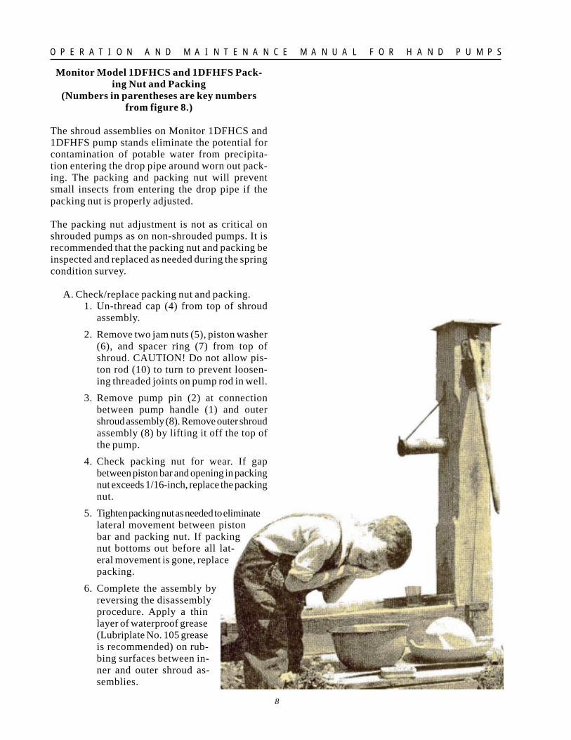
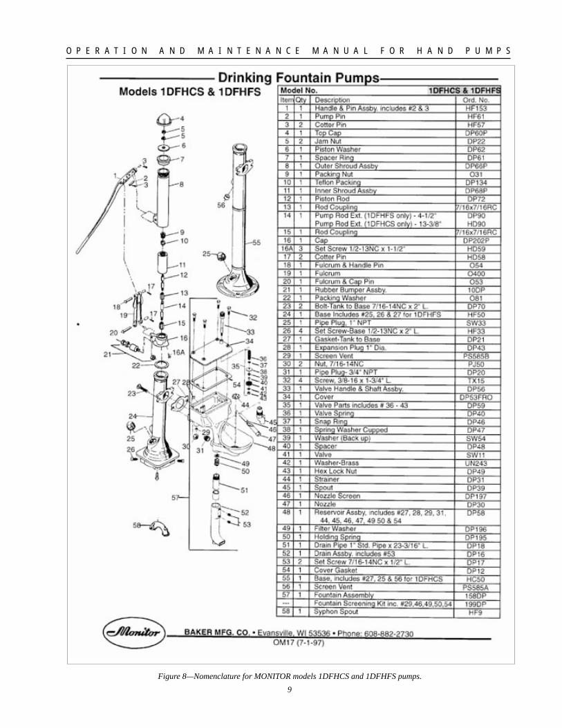
Monitor Model 1DFHCS and 1DFHFS Pack-ing Nut and Packing
(Numbers in parentheses are key numbersfrom figure 8.)
The shroud assemblies on Monitor 1DFHCS and1DFHFS pump stands eliminate the potential forcontamination of potable water from precipita-tion entering the drop pipe around worn out pack-ing. The packing and packing nut will preventsmall insects from entering the drop pipe if thepacking nut is properly adjusted.
The packing nut adjustment is not as critical onshrouded pumps as on non-shrouded pumps. It isrecommended that the packing nut and packing beinspected and replaced as needed during the springcondition survey.
A. Check/replace packing nut and packing.1. Un-thread cap (4) from top of shroud
assembly.
2. Remove two jam nuts (5), piston washer(6), and spacer ring (7) from top ofshroud. CAUTION! Do not allow pis-ton rod (10) to turn to prevent loosen-ing threaded joints on pump rod in well.
3. Remove pump pin (2) at connectionbetween pump handle (1) and outershroud assembly (8). Remove outer shroudassembly (8) by lifting it off the top ofthe pump.
4. Check packing nut for wear. If gapbetween piston bar and opening in packingnut exceeds 1/16-inch, replace the packingnut.
5. Tighten packing nut as needed to eliminatelateral movement between pistonbar and packing nut. If packingnut bottoms out before all lat-eral movement is gone, replacepacking.
6. Complete the assembly byreversing the disassemblyprocedure. Apply a thinlayer of waterproof grease(Lubriplate No. 105 greaseis recommended) on rub-bing surfaces between in-ner and outer shroud as-semblies.
9
O P E R A T I O N A N D M A I N T E N A N C E M A N U A L F O R H A N D P U M P S
Figure 8—Nomenclature for MONITOR models 1DFHCS and 1DFHFS pumps.
10
O P E R A T I O N A N D M A I N T E N A N C E M A N U A L F O R H A N D P U M P S
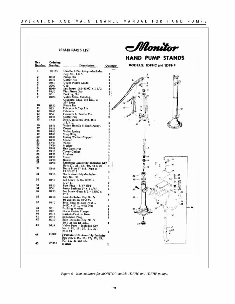
Figure 9—Nomenclature for MONITOR models 1DFHC and 1DFHF pumps.
11
O P E R A T I O N A N D M A I N T E N A N C E M A N U A L F O R H A N D P U M P S
Monitor Model 1DFHC and 1DFHF PackingNut, Packing, and Upper Piston Guide
(Numbers in parentheses are key numbersfrom figure 9)
Properly maintaining the pump rod packing is oneof the most important items in protecting thesanitary quality of the water from this hand pump.The packing nut (8) is located at the top of thepump base. The packing nut and packing (9) forma watertight seal where the piston bar (10) movesup and down through the top of the pump base(36). Normal maintenance will require the peri-odic tightening of the packing nut to compress thepacking against the piston bar to maintain thewatertight seal. The packing nut should be tight-ened to the point that there is no side movement inthe piston bar through the nut and there is a slightdrag on the piston bar when the pump is operated.If water bubbles around the packing, the packingnut is not tight enough.
The packing nut should not show much wear if thepacking is properly maintained because the pistonbar should rub against the packing, not the brasspacking nut. If the packing nut is not tightenedperiodically, and the packing is not replaced whenrequired, the brass packing nut will show wear. Ifthe wear on the packing nut is allowed to con-tinue, ultimately the hole in the packing nut andthe lower guide flange (39) will become ovalshaped. If this happens, the packing nut and thelower guide flange should be replaced because thepacking may not stay in place if the oval becomestoo pronounced.
The upper piston guide (4) will wear in the direc-tion of the pump handle as the flat piston bar (7)rubs against the guide. As the upper piston guidewears, the piston bar (10) will tend to ware oneside of the packing nut. The watertight seal at thepacking nut may be disrupted if the packing nutwears to one side. A thin layer of waterproofgrease (Lubriplate No. 105) on the upper pistonguide and the handle side of the flat piston barshould prolong the life of the guide. Replace theupper piston guide when wear exceeds 1/8 inch.
Note: Upper piston guide (4) and flat piston bar(7) may be rotated 180 degrees one time to doublethe life of these two components.
The procedures for replacing the packing, packingnut, and upper piston guide are described below.
A. Replace packing.
1. Loosen packing nut (8) and slide nut uppiston bar (10) to provide access to packing (9).
2. Remove remainder of old packing with afine-pointed tool such as a small screw-driver, etc.
3. Install new valve stem packing (9) as rec-ommended by pump manufacturer (Graph-ite rope 1/8" diameter x 23" long for Moni-tor brand pumps). Some districts have triedTeflon packing such as Zip Joint in place ofgraphite rope packing. The piston bar staysclean and there is no gummy residue left onthe packing nut.
4. Slide packing nut down piston bar and tightento form watertight seal.
B. Replace packing nut (and packing, if needed).
1. Remove pump pin (2) at connection be-tween pump handle (1) and flat piston bar (7).
2. Remove upper piston guide (4) and un-threadflat piston bar (7) from piston bar (10).
3. Loosen packing nut (8) and remove by slid-ing up the piston bar (10).
4. Replace pump packing (9), if needed.
5. Install new packing nut by sliding downover the piston bar and tighten to form awatertight seal. Complete the assembly byreversing the disassembly procedure. Thesmooth surface of the piston bar (10) thatslides through the packing (9) and the pack-ing nut (8) should not be scratched or gougedwith the jaws of pliers, pipe wrenches, etc.Damaging the surface of the piston bar willcause rapid failure of the packing.
C. Replace upper piston guide.
1. Remove pump pin (2) at connection be-tween pump handle (1) and flat piston bar (7).
2. Upper piston guide (4) has to be rotated 1/4turn inside pump cap (5) before the guidecan be lifted out of the cap. On shallowwells, this can be accomplished by putting around rod through the hole in the flat pistonbar, lifting the flat piston bar about _-inchwith the round rod, and turning the flatpiston bar counter clockwise 1/4 turn. Ondeep pump installations, loosen the three set
12
O P E R A T I O N A N D M A I N T E N A N C E M A N U A L F O R H A N D P U M P S
Figure 10—MONITOR pump cylinder components.
13
O P E R A T I O N A N D M A I N T E N A N C E M A N U A L F O R H A N D P U M P S
screws (6) at the base of the cap, and rotatethe cap 1/4 clockwise, holding the flat pis-ton bar so it does not turn.
3. Lift out the upper piston guide, replace orrotate 180 degrees, and put it back on the topof the pump cap (5). Complete the assemblyby reversing the disassembly procedure.
VII. SPARE PARTSThe following is a list of common spare parts withkey numbers that districts should consider stock-ing for hand pump maintenance.
Key NumberItem (see figures 8 and 9)
Packing nuts 9, 8
Graphite rope or Teflon packing 10, 9
Upper piston guide(not on shrouded pumps) 4
Reservoir cover 34,17
Gaskets:
Reservoir cover 54, 25
Packing washer 22, 38
Tank-to-base 27, 40
Using a standard brand of hand pump on a districtwill reduce the inventory of recommended spareparts.
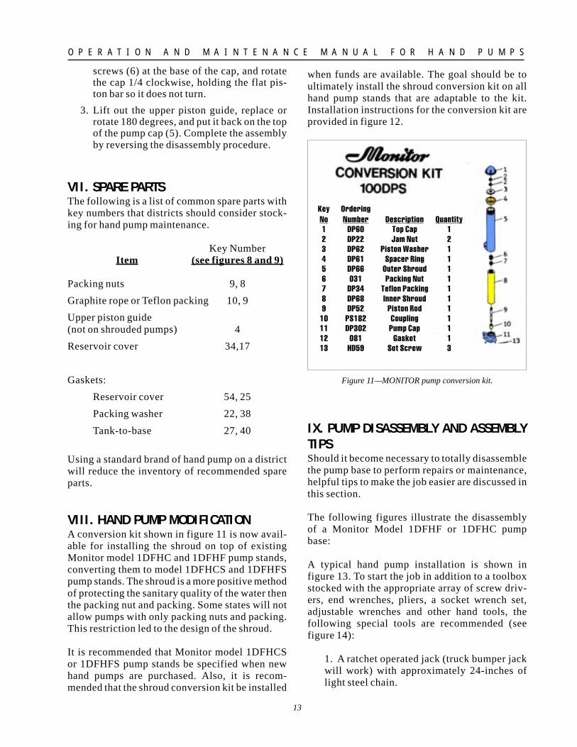
VIII. HAND PUMP MODIFICATIONA conversion kit shown in figure 11 is now avail-able for installing the shroud on top of existingMonitor model 1DFHC and 1DFHF pump stands,converting them to model 1DFHCS and 1DFHFSpump stands. The shroud is a more positive methodof protecting the sanitary quality of the water thenthe packing nut and packing. Some states will notallow pumps with only packing nuts and packing.This restriction led to the design of the shroud.
It is recommended that Monitor model 1DFHCSor 1DFHFS pump stands be specified when newhand pumps are purchased. Also, it is recom-mended that the shroud conversion kit be installed
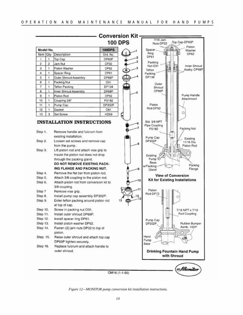
when funds are available. The goal should be toultimately install the shroud conversion kit on allhand pump stands that are adaptable to the kit.Installation instructions for the conversion kit areprovided in figure 12.
Figure 11—MONITOR pump conversion kit.
IX. PUMP DISASSEMBLY AND ASSEMBLYTIPSShould it become necessary to totally disassemblethe pump base to perform repairs or maintenance,helpful tips to make the job easier are discussed inthis section.
The following figures illustrate the disassemblyof a Monitor Model 1DFHF or 1DFHC pumpbase:
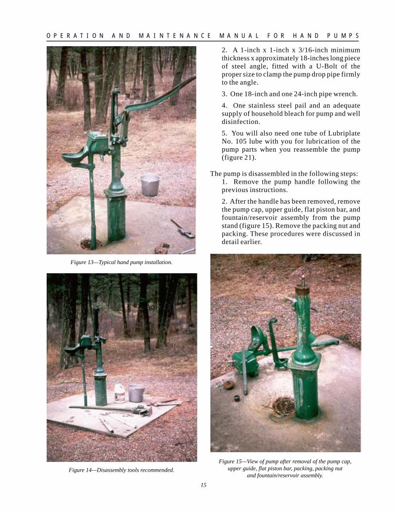
A typical hand pump installation is shown infigure 13. To start the job in addition to a toolboxstocked with the appropriate array of screw driv-ers, end wrenches, pliers, a socket wrench set,adjustable wrenches and other hand tools, thefollowing special tools are recommended (seefigure 14):
1. A ratchet operated jack (truck bumper jackwill work) with approximately 24-inches oflight steel chain.
Key OrderingNo Number Description Quantity1 DP60 Top Cap 12 DP22 Jam Nut 23 DP62 Piston Washer 14 DP61 Spacer Ring 15 DP66 Outer Shroud 16 O31 Packing Nut 17 DP34 Teflon Packing 18 DP68 Inner Shroud 19 DP52 Piston Rod 1
10 PS182 Coupling 111 DP302 Pump Cap 112 O81 Gasket 113 HD59 Set Screw 3
14
O P E R A T I O N A N D M A I N T E N A N C E M A N U A L F O R H A N D P U M P S
Figure 12—MONITOR pump conversion kit installation instructions.
15
O P E R A T I O N A N D M A I N T E N A N C E M A N U A L F O R H A N D P U M P S
2. A 1-inch x 1-inch x 3/16-inch minimumthickness x approximately 18-inches long pieceof steel angle, fitted with a U-Bolt of theproper size to clamp the pump drop pipe firmlyto the angle.
3. One 18-inch and one 24-inch pipe wrench.
4. One stainless steel pail and an adequatesupply of household bleach for pump and welldisinfection.
5. You will also need one tube of LubriplateNo. 105 lube with you for lubrication of thepump parts when you reassemble the pump(figure 21).
The pump is disassembled in the following steps:1. Remove the pump handle following theprevious instructions.
2. After the handle has been removed, removethe pump cap, upper guide, flat piston bar, andfountain/reservoir assembly from the pumpstand (figure 15). Remove the packing nut andpacking. These procedures were discussed indetail earlier.
Figure 15—View of pump after removal of the pump cap,upper guide, flat piston bar, packing, packing nut
and fountain/reservoir assembly.
Figure 13—Typical hand pump installation.
Figure 14—Disassembly tools recommended.
16
O P E R A T I O N A N D M A I N T E N A N C E M A N U A L F O R H A N D P U M P S
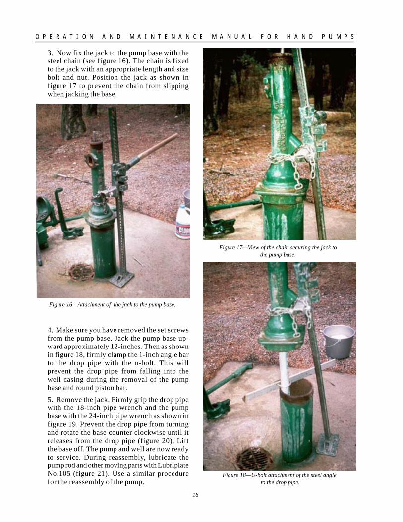
3. Now fix the jack to the pump base with thesteel chain (see figure 16). The chain is fixedto the jack with an appropriate length and sizebolt and nut. Position the jack as shown infigure 17 to prevent the chain from slippingwhen jacking the base.
4. Make sure you have removed the set screwsfrom the pump base. Jack the pump base up-ward approximately 12-inches. Then as shownin figure 18, firmly clamp the 1-inch angle barto the drop pipe with the u-bolt. This willprevent the drop pipe from falling into thewell casing during the removal of the pumpbase and round piston bar.
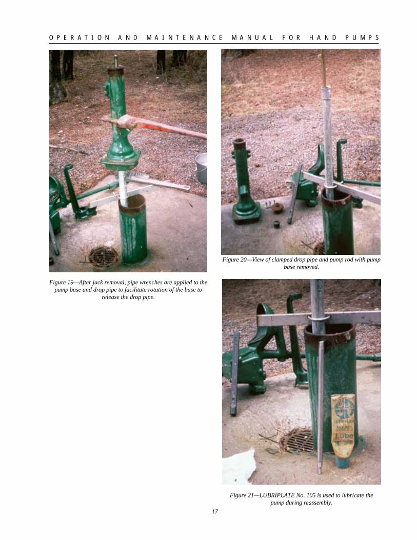
5. Remove the jack. Firmly grip the drop pipewith the 18-inch pipe wrench and the pumpbase with the 24-inch pipe wrench as shown infigure 19. Prevent the drop pipe from turningand rotate the base counter clockwise until itreleases from the drop pipe (figure 20). Liftthe base off. The pump and well are now readyto service. During reassembly, lubricate thepump rod and other moving parts with LubriplateNo.105 (figure 21). Use a similar procedurefor the reassembly of the pump.
Figure 16—Attachment of the jack to the pump base.
Figure 17—View of the chain securing the jack tothe pump base.
Figure 18—U-bolt attachment of the steel angle to the drop pipe.
17
O P E R A T I O N A N D M A I N T E N A N C E M A N U A L F O R H A N D P U M P S
Figure 19—After jack removal, pipe wrenches are applied to thepump base and drop pipe to facilitate rotation of the base to
release the drop pipe.
Figure 20—View of clamped drop pipe and pump rod with pumpbase removed.
Figure 21—LUBRIPLATE No. 105 is used to lubricate thepump during reassembly.