operation and maintenance guide hydrological equipment gurley...
TRANSCRIPT

1
2
Gurley Precision Instruments Hydrological Equipment
Operation and Maintenance Guide
The Company Gurley Precision Instruments was founded in 1845, and has sustained continuous operation to date at its original production facilities. Since its inception as a manufacturer of compasses, surveying instruments and brass castings, the company has become a leader in the field of precision measuring instruments. In April of 1968, the company became a division of Teledyne Incorporated, resulting in its ability to offer extensive experi-ence and unusual depth of resources. Today, Gurley continues to uphold its long stood reputation for quality and progress in precision instruments. Company History 1845 – 1968 W & L.E. Gurley 1968 – 1993 Teledyne Gurley 1993 – present Gurley Precision Instruments Genuine GurleyTM Precision Instruments since 1845 514 Fulton Street Troy, NY 12181-0088 Tel: (518) 272-6300 Fax: (518) 274-0336 Toll Free: (800) 759-1844 www.gurley.com [email protected]
3
Page
5 5 6
8
10
12
14 16
16
18 20
22
24 26 26
28
30
32
34
36
Contents
Overview of this Guide How to use this guide Measurement procedures
Part 1 – Assembling the Complete Measuring System
Cable System Assembling the cable system
(Model 622A or 622D Price Meter) Connecting electrical leads to headphones Connecting electrical leads to Model 1100
Digital Flow Velocity Indicator Wading Rod System
Assembling the wading rod system (Model 622A or 622D Price Meter)
Assembling the wading rod system (Model 625A or 625D pygmy meter)
Connecting electrical leads to headphones Connecting electrical leads to the Model 1100
Digital Flow Velocity Indicator Part 2 – Maintaining Price and Pygmy Meters and Headphones
Price Meter Cleaning and lubricating the meter Adjusting the pivot
(Model 622A Price meter, headphone style) Adjusting the pivot
(Model 622D Price meter, digital style) Adjusting the contact wire
(Model 622A Price meter, headphone style) Disassembling the meter
(Model 622A Price meter, headphone style) Disassembling the meter
(Model 622D Price meter, digital style)
4
Pygmy Meter Cleaning and lubricating the meter
Adjusting the pivot (Model 625A pygmy meter, headphone style)
Adjusting the pivot (Model 625D pygmy meter, digital style)
Adjusting the contact wire (Model 625A pygmy meter, headphone style)
Disassembling the meter (Model 625A pygmy meter, headphone style)
Disassembling the meter (Model 625D pygmy meter, digital style)
Headphones
Part 3 – Using the Model 1100 Digital Flow Velocity Indicator Understanding the panel functions Performing a self-test Operating the Model 1100
Automatic Mode Averaging Mode Manual Mode
Part 4 – Converting Headphone Style Meters to Digital
Converting the Price 622-AA meter Converting the pygmy 625A meter Caring for the opto-sensor assembly
Part 5 – Repair Parts
Wading Rod Sets Wading Rod Parts and Accessories Batteries Cable Suspension Equipment Current Meter Parts, Headphone Style Current Meter Parts, Digital Style
Page 38 38
40
42
44
46
48 50
52 54 56 57 57 57 58
60 62 64 64
66 66 66 67 67
68, 69 70

5
Overview of Guide This manual contains complete instructions and illustrations for the assem-bly and maintenance of Gurley hydrological measuring equipment. Gurley Hydrological measuring outfits consist of three basic components: the me-ter (Price or pygmy), the suspension system (cable or rod), and the detec-tor (headphone, Model 1100 digital flow indicator). These components must be properly assembled, maintained, and operated in order for the outfit to function as designed. Using the Hydro-logical Equipment Operation and Maintenance Guide, you can easily as-semble, maintain and operate any measuring outfit configuration. How to use this guide The components of Gurley hydrological systems are modular in nature, so that you can assemble the outfit that best suits a particular site. To locate the instructions that pertain to the components of your outfit, see the de-tailed table of contents. The guide is divided into five parts:
Part 1 – Assembling the complete measuring system Part 2 – Maintaining Price and Pygmy Meters and Headphones Part 3 – Using the Model 1100 Digital Flow Velocity Indicator Part 4 – Converting Headphone Style Meters to Digital Part 5 – Repair Parts
Within the first four parts are sections that describe individual tasks or components. Part 5 contains parts listed for the equipment described. Rating tables are located immediately inside the back cover. The step-by-step instructions for completing each task are accompanied by photographs of the equipment with parts clearly labeled. Instructions appear in the right-hand page, and illustrations on the facing left-hand page.
6
Because the assembly and maintenance operations are relatively simple, you may need to use these detailed instructions only once or twice. From then on, refer to the guide for seldom-performed procedures, to refresh your memory, or for part numbers. Its compact size means you can carry it with you in the field.
Measurement procedures Price and pygmy meters satisfy U.S. Geological Survey requirements for Type AA current meters when used according to standard procedures. This guide does not include measurement procedures. Model Comparison Chart
*Can be converted for use with the new model 1100 digital indicator. Replacement parts and service for most discontinued products is avail-able.
Model Type Status
622A 622D 625A 625D 645* 665* 667* 675* 700
Price – headphone (analog) Price – digital Pygmy–headphone (analog) Pygmy – digital Pygmy - old digital Price – analog Price – analog Price – old digital Old style digital indicator
Available Available Available Available Replaced by 625D Replaced by 622A and 622D Replaced by 622A and 622D Replaced by 622D Replaced by 1100 indicator
7 8
Part 1 Assembling the Complete Measuring System To assemble a complete measuring system, you must first assemble the suspension system (cable or wading rod), and then connect the electrical leads to the detector (headphones, Model 1100). This part of the guide has two sections – one for a cable suspension sys-tem and one for a rod suspension system. Within each of these sections are instructions for assembling the system and for connecting the electri-cal leads to detectors.
9
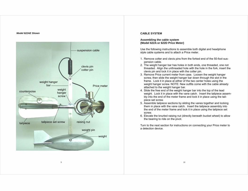
Model 622AE Shown
10
CABLE SYSTEM Assembling the cable system (Model 622A or 622D Price Meter) Use the following instructions to assemble both digital and headphone style cable systems and to attach a Price meter. 1. Remove cotter and clevis pins from the forked end of the 50-foot sus-
pension cable. 2. The weight hanger bar has holes in both ends, one threaded, one not
threaded. Align the unthreaded hole with the hole in the fork, insert the clevis pin and lock it in place with the cotter pin.
3. Remove Price current meter from case. Loosen the weight hanger screw, then slide the weight hanger bar down through the slot in the frame. Lock it in place at either of the two center holes using the weight hanger screw. NOTE: New outfits come with the cable already attached to the weight hanger bar.
4. Slide the free end of the weight hanger bar into the top of the lead weight. Lock it in place with the vane catch. Insert the tailpiece assem-bly into the end of the meter frame and lock it in place using the tail-piece set screw.
5. Assemble tailpiece sections by sliding the vanes together and locking them in place with the vane catch. Insert the tailpiece assembly into the end of the meter frame and lock it in place using the tailpiece set screw.
6. Elevate the knurled raising nut (directly beneath bucket wheel) to allow the bearing to ride on the pivot.
Turn to the next section for instructions on connecting your Price meter to a detection device.
11
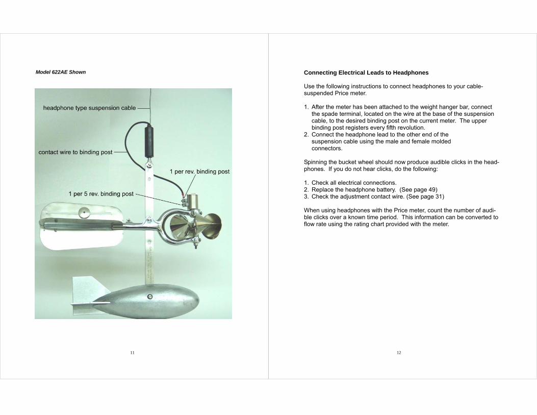
Model 622AE Shown
12
Connecting Electrical Leads to Headphones Use the following instructions to connect headphones to your cable-suspended Price meter. 1. After the meter has been attached to the weight hanger bar, connect
the spade terminal, located on the wire at the base of the suspension cable, to the desired binding post on the current meter. The upper binding post registers every fifth revolution.
2. Connect the headphone lead to the other end of the suspension cable using the male and female molded connectors.
Spinning the bucket wheel should now produce audible clicks in the head-phones. If you do not hear clicks, do the following: 1. Check all electrical connections. 2. Replace the headphone battery. (See page 49) 3. Check the adjustment contact wire. (See page 31) When using headphones with the Price meter, count the number of audi-ble clicks over a known time period. This information can be converted to flow rate using the rating chart provided with the meter.
13
Model 622DE Shown
14
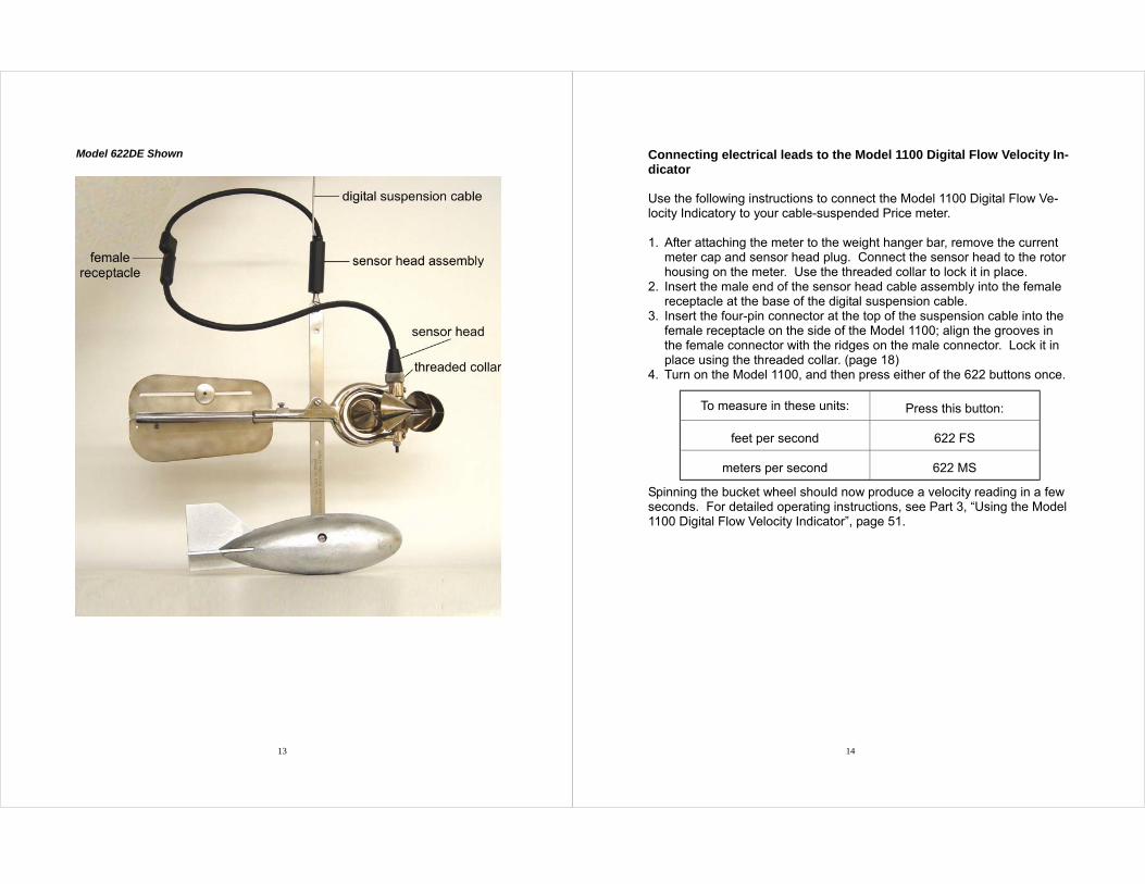
Connecting electrical leads to the Model 1100 Digital Flow Velocity In-dicator Use the following instructions to connect the Model 1100 Digital Flow Ve-locity Indicatory to your cable-suspended Price meter. 1. After attaching the meter to the weight hanger bar, remove the current
meter cap and sensor head plug. Connect the sensor head to the rotor housing on the meter. Use the threaded collar to lock it in place.
2. Insert the male end of the sensor head cable assembly into the female receptacle at the base of the digital suspension cable.
3. Insert the four-pin connector at the top of the suspension cable into the female receptacle on the side of the Model 1100; align the grooves in the female connector with the ridges on the male connector. Lock it in place using the threaded collar. (page 18)
4. Turn on the Model 1100, and then press either of the 622 buttons once. Spinning the bucket wheel should now produce a velocity reading in a few seconds. For detailed operating instructions, see Part 3, “Using the Model 1100 Digital Flow Velocity Indicator”, page 51.
To measure in these units: Press this button:
feet per second 622 FS
meters per second 622 MS
15
Model 622AF Shown
16
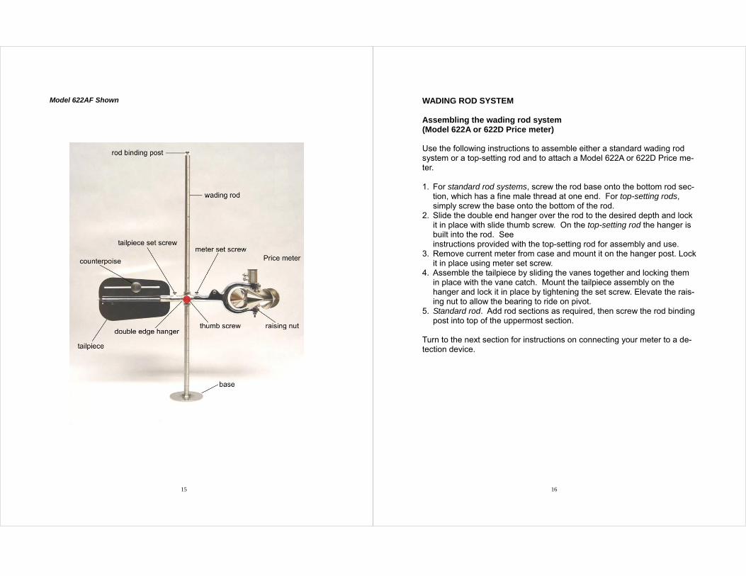
WADING ROD SYSTEM Assembling the wading rod system (Model 622A or 622D Price meter) Use the following instructions to assemble either a standard wading rod system or a top-setting rod and to attach a Model 622A or 622D Price me-ter. 1. For standard rod systems, screw the rod base onto the bottom rod sec-
tion, which has a fine male thread at one end. For top-setting rods, simply screw the base onto the bottom of the rod.
2. Slide the double end hanger over the rod to the desired depth and lock it in place with slide thumb screw. On the top-setting rod the hanger is built into the rod. See instructions provided with the top-setting rod for assembly and use.
3. Remove current meter from case and mount it on the hanger post. Lock it in place using meter set screw.
4. Assemble the tailpiece by sliding the vanes together and locking them in place with the vane catch. Mount the tailpiece assembly on the hanger and lock it in place by tightening the set screw. Elevate the rais-ing nut to allow the bearing to ride on pivot.
5. Standard rod. Add rod sections as required, then screw the rod binding post into top of the uppermost section.
Turn to the next section for instructions on connecting your meter to a de-tection device.
17
Model 625AF Shown
18
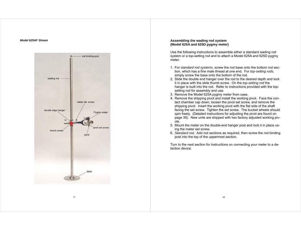
Assembling the wading rod system (Model 625A and 625D pygmy meter) Use the following instructions to assemble either a standard wading rod system or a top-setting rod and to attach a Model 625A and 625D pygmy meter. 1. For standard rod systems, screw the rod base onto the bottom rod sec-
tion, which has a fine male thread at one end. For top-setting rods, simply screw the base onto the bottom of the rod.
2. Slide the double end hanger over the rod to the desired depth and lock it in place with the slide thumb screw. On the top-setting rod the hanger is built into the rod. Refer to instructions provided with the top-setting rod for assembly and use.
3. Remove the Model 625A pygmy meter from case. 4. Remove the shipping pivot and install the working pivot. Face the con-
tact chamber cap down, loosen the pivot set screw, and remove the shipping pivot. Insert the working pivot with the flat side of the shaft facing the set screw. Tighten the set screw. The bucket wheels should spin freely. (Detailed instructions for adjusting the pivot are found on page 39). New units are shipped with two factory adjusted working piv-ots.
5. Mount the meter on the double-end hanger post and lock it in place us-ing the meter set screw.
6. Standard rod. Add rod sections as required, then screw the rod binding post into the top of the uppermost section.
Turn to the next section for instructions on connecting your meter to a de-tection device.
19 20
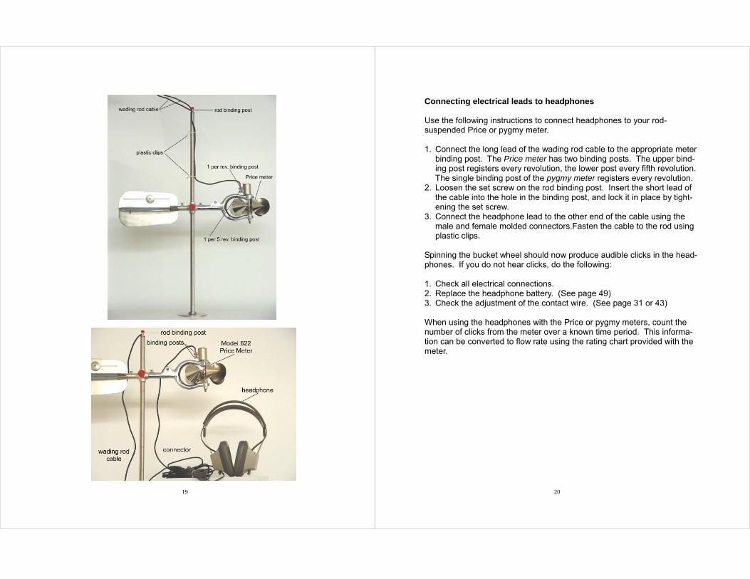
Connecting electrical leads to headphones Use the following instructions to connect headphones to your rod-suspended Price or pygmy meter. 1. Connect the long lead of the wading rod cable to the appropriate meter
binding post. The Price meter has two binding posts. The upper bind-ing post registers every revolution, the lower post every fifth revolution. The single binding post of the pygmy meter registers every revolution.
2. Loosen the set screw on the rod binding post. Insert the short lead of the cable into the hole in the binding post, and lock it in place by tight-ening the set screw.
3. Connect the headphone lead to the other end of the cable using the male and female molded connectors.Fasten the cable to the rod using plastic clips.
Spinning the bucket wheel should now produce audible clicks in the head-phones. If you do not hear clicks, do the following: 1. Check all electrical connections. 2. Replace the headphone battery. (See page 49) 3. Check the adjustment of the contact wire. (See page 31 or 43) When using the headphones with the Price or pygmy meters, count the number of clicks from the meter over a known time period. This informa-tion can be converted to flow rate using the rating chart provided with the meter.
21
Model 622DF Shown
22
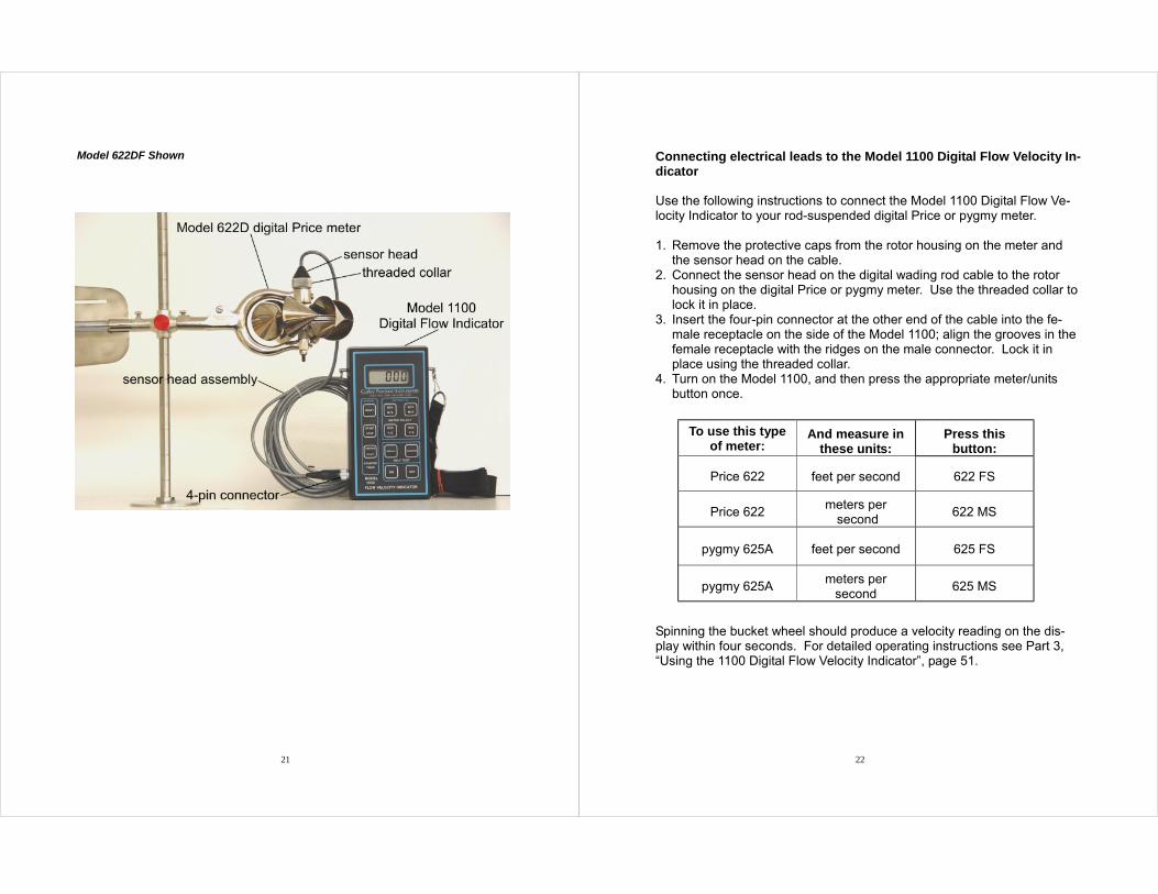
Connecting electrical leads to the Model 1100 Digital Flow Velocity In-dicator Use the following instructions to connect the Model 1100 Digital Flow Ve-locity Indicator to your rod-suspended digital Price or pygmy meter. 1. Remove the protective caps from the rotor housing on the meter and
the sensor head on the cable. 2. Connect the sensor head on the digital wading rod cable to the rotor
housing on the digital Price or pygmy meter. Use the threaded collar to lock it in place.
3. Insert the four-pin connector at the other end of the cable into the fe-male receptacle on the side of the Model 1100; align the grooves in the female receptacle with the ridges on the male connector. Lock it in place using the threaded collar.
4. Turn on the Model 1100, and then press the appropriate meter/units button once.
Spinning the bucket wheel should produce a velocity reading on the dis-play within four seconds. For detailed operating instructions see Part 3, “Using the 1100 Digital Flow Velocity Indicator”, page 51.
To use this type of meter:
And measure in these units:
Press this button:
Price 622 feet per second 622 FS
Price 622 meters per
second 622 MS
pygmy 625A feet per second 625 FS
pygmy 625A meters per
second 625 MS
23 24
Part 2 Maintaining Price and Pygmy Meters and Headphones Your price meters will give you years of accurate readings if you maintain them properly. This part of the guide contains one section for Price meter maintenance and one for pygmy meter maintenance. An additional sec-tion describes how to replace the battery in the headphones.

25 26
PRICE METER Cleaning and lubricating the meter To ensure proper operation, the current meter must be cleaned and lubri-cated at the end of each day’s use. Complete the following instructions to clean and lubricate your Price meter. 1. Remove the contact chamber map. 2. Loosen the pivot set screw and remove the pivot,. 3. Clean and dry the pivot with a soft cloth. Set it aside. 4. Clean the lower bearing with a small pointed stick or a cotton swab. 5. Hold the current meter with the contact chamber up. Place a small
drop of oil in the bearing, insert the pivot with the flat side of the shaft toward the set screw, and lock it in place using the pivot set screw.
6. Hold the current meter with the contact chamber up. Oil the top of the shaft, steady bearing, worm and gear, as well as the gear bearing.
7. Replace the chamber up. Follow this procedure after each use to help prevent rust. If the meter is to be stored for extended periods of time, cover the pivot and bearing with grease. NOTE: After cleaning and lubricating the meter at the end of each day’s use, lower the raising nut under the bucket wheel assembly to take pres-sure off the pivot.
27 28
Adjusting the pivot (Model 622A Price Meter, headphone style) Use the following instructions to adjust the pivot on your headphone style Price meter. 1. With the contact chamber tightly in place, invert the current meter so
that the top of the shaft rests against the inside of the cap. 2. Loosen both the nut on the bottom of the pivot and the set screw. With
the flat side of the shaft facing the pivot set screw, insert pivot until there is no vertical play in the shaft. Lock it in place using the vertical set screw.
3. Advance the pivot-adjusting nut until it rests against the frame. 4. Loosen the set screw slightly and advance the pivot-adjusting nut one
quarter of a turn, making sure the pivot us not turning. Tighten the set screw.
This adjustment provides an endplay of about 0.008-inch. It is essential that this adjustment be made when replacing a pivot.
29 30
Adjusting the pivot (Model 622D Price Meter, digital style) Use the following instructions to adjust the pivot on your digital style Price meter. 1. Invert the current meter so that the shoulder of the hub extension rests
against the bottom of the rotor housing. 2. Loosen both the nut on the bottom of the pivot and the set screw. In-
sert the pivot into the lower bearing with the flat side facing the pivot set screw, until there is no vertical play in the hub extension. Lock it in place using the set screw.
3. Advance the pivot adjusting nut until is rests against the frame. 4. Loosen the set screw slightly and advance the adjusting nut one quar-
ter of a turn, making sure the pivot does not turn. Tighten the set screw.
This adjustment provides an endplay of about 0.008 inch. It is essential that this adjustment be made when replacing a pivot
31 32
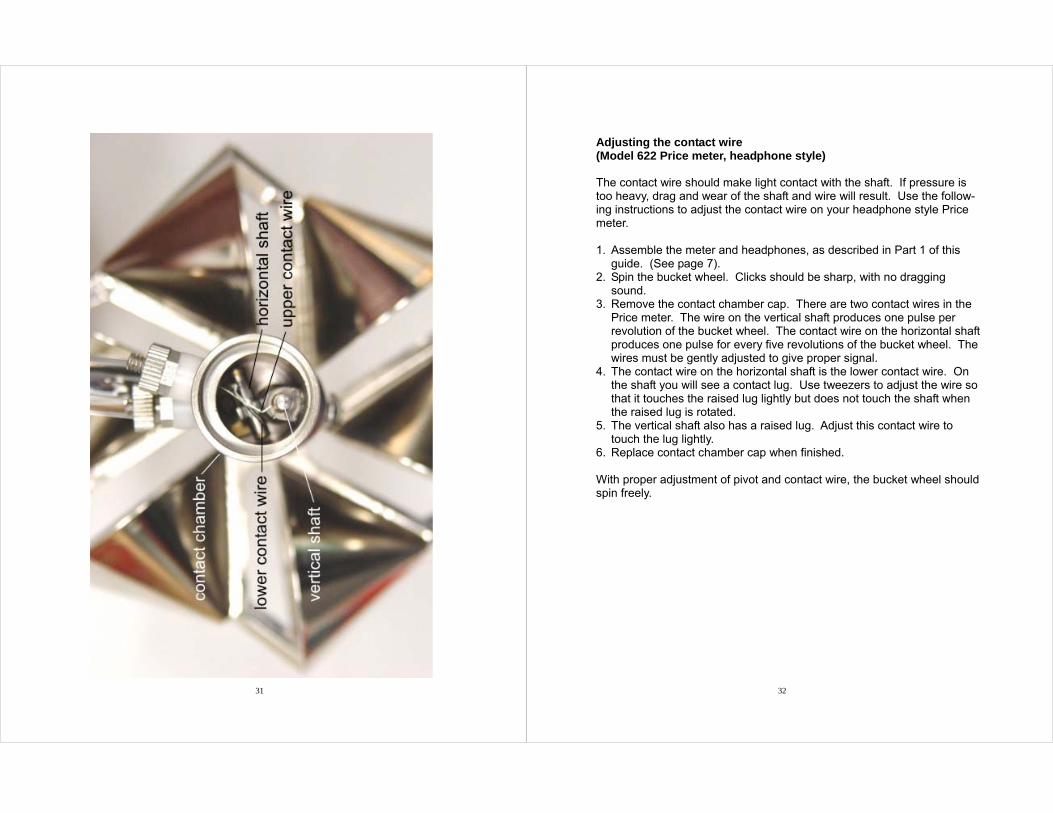
Adjusting the contact wire (Model 622 Price meter, headphone style) The contact wire should make light contact with the shaft. If pressure is too heavy, drag and wear of the shaft and wire will result. Use the follow-ing instructions to adjust the contact wire on your headphone style Price meter. 1. Assemble the meter and headphones, as described in Part 1 of this
guide. (See page 7). 2. Spin the bucket wheel. Clicks should be sharp, with no dragging
sound. 3. Remove the contact chamber cap. There are two contact wires in the
Price meter. The wire on the vertical shaft produces one pulse per revolution of the bucket wheel. The contact wire on the horizontal shaft produces one pulse for every five revolutions of the bucket wheel. The wires must be gently adjusted to give proper signal.
4. The contact wire on the horizontal shaft is the lower contact wire. On the shaft you will see a contact lug. Use tweezers to adjust the wire so that it touches the raised lug lightly but does not touch the shaft when the raised lug is rotated.
5. The vertical shaft also has a raised lug. Adjust this contact wire to touch the lug lightly.
6. Replace contact chamber cap when finished. With proper adjustment of pivot and contact wire, the bucket wheel should spin freely.
33 34
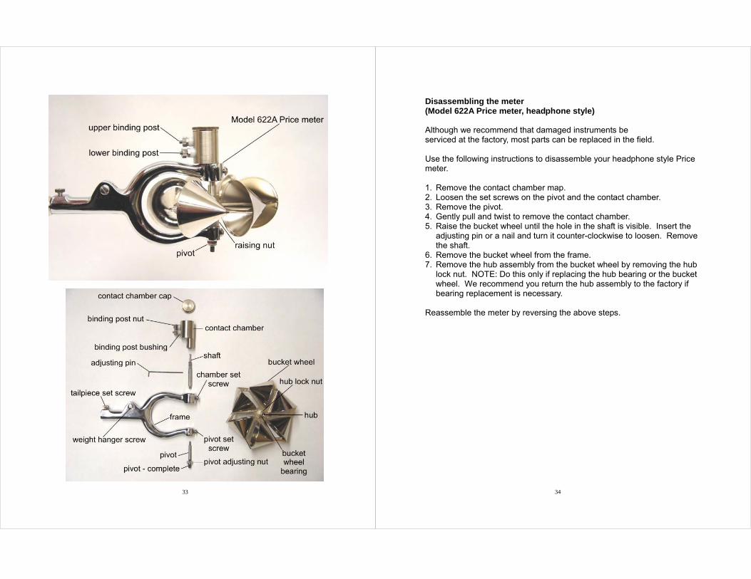
Disassembling the meter (Model 622A Price meter, headphone style) Although we recommend that damaged instruments be serviced at the factory, most parts can be replaced in the field. Use the following instructions to disassemble your headphone style Price meter. 1. Remove the contact chamber map. 2. Loosen the set screws on the pivot and the contact chamber. 3. Remove the pivot. 4. Gently pull and twist to remove the contact chamber. 5. Raise the bucket wheel until the hole in the shaft is visible. Insert the
adjusting pin or a nail and turn it counter-clockwise to loosen. Remove the shaft.
6. Remove the bucket wheel from the frame. 7. Remove the hub assembly from the bucket wheel by removing the hub
lock nut. NOTE: Do this only if replacing the hub bearing or the bucket wheel. We recommend you return the hub assembly to the factory if bearing replacement is necessary.
Reassemble the meter by reversing the above steps.
35 36
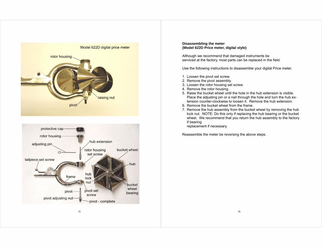
Disassembling the meter (Model 622D Price meter, digital style) Although we recommend that damaged instruments be serviced at the factory, most parts can be replaced in the field. Use the following instructions to disassemble your digital Price meter. 1. Loosen the pivot set screw. 2. Remove the pivot assembly. 3. Loosen the rotor housing set screw. 4. Remove the rotor housing. 5. Raise the bucket wheel until the hole in the hub extension is visible.
Place the adjusting pin or a nail through the hole and turn the hub ex-tension counter-clockwise to loosen it. Remove the hub extension.
6. Remove the bucket wheel from the frame. 7. Remove the hub assembly from the bucket wheel by removing the hub
lock nut. NOTE: Do this only if replacing the hub bearing or the bucket wheel. We recommend that you return the hub assembly to the factory if bearing replacement if necessary.
Reassemble the meter be reversing the above steps.
37 38
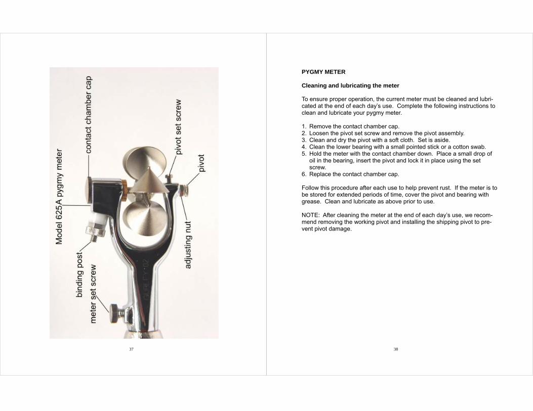
PYGMY METER Cleaning and lubricating the meter To ensure proper operation, the current meter must be cleaned and lubri-cated at the end of each day’s use. Complete the following instructions to clean and lubricate your pygmy meter. 1. Remove the contact chamber cap. 2. Loosen the pivot set screw and remove the pivot assembly. 3. Clean and dry the pivot with a soft cloth. Set is aside. 4. Clean the lower bearing with a small pointed stick or a cotton swab. 5. Hold the meter with the contact chamber down. Place a small drop of
oil in the bearing, insert the pivot and lock it in place using the set screw.
6. Replace the contact chamber cap. Follow this procedure after each use to help prevent rust. If the meter is to be stored for extended periods of time, cover the pivot and bearing with grease. Clean and lubricate as above prior to use. NOTE: After cleaning the meter at the end of each day’s use, we recom-mend removing the working pivot and installing the shipping pivot to pre-vent pivot damage.
39 40
Adjusting the pivot (Model 625A pygmy meter, headphone style) Use the following instructions to adjust the pivot on your headphone style pygmy meter. 1. With the contact chamber cap tightly in place, invert the current meter. 2. Loosen the pivot-adjusting nut and the pivot set screw. Insert the pivot
into the lower bearing with the flat side facing the pivot set screw, until there is no vertical play in the shaft. Lock it in place using the set screw.
3. Advance the pivot adjusting nut until it rests against the frame. 4. Loosen the set screw slightly and advance the pivot adjusting not one
quarter of a turn, making sure the pivot is not turning. Tighten the set screw.
This adjustment provides an endplay of about 0.008 inch. It is essential that this adjustment be made when replacing a pivot.
41 42
Adjusting the pivot (Model 625D pygmy meter, digital style) Use the following instructions to adjust the pivot on your digital style pygmy meter. 1. Invert the current meter so that the shoulder of the hub extension rests
against the bottom of the rotor housing. 2. Loosen the pivot-adjusting nut and the pivot set screw. Insert the pivot
into the lower bearing with the flat side facing the pivot set screw, until there is no vertical play in the hub extension. Lock it in place using the set screw.
3. Advance the pivot-adjusting nut until it rests against the frame. 4. Loosen the set screw slightly and advance the adjusting nut one quar-
ter of a turn, making sure the pivot does not turn. Tighten the set screw.
This adjustment provides and endplay of about 0.008 inch. It is essential that this adjustment be made when replacing a pivot.
43 44
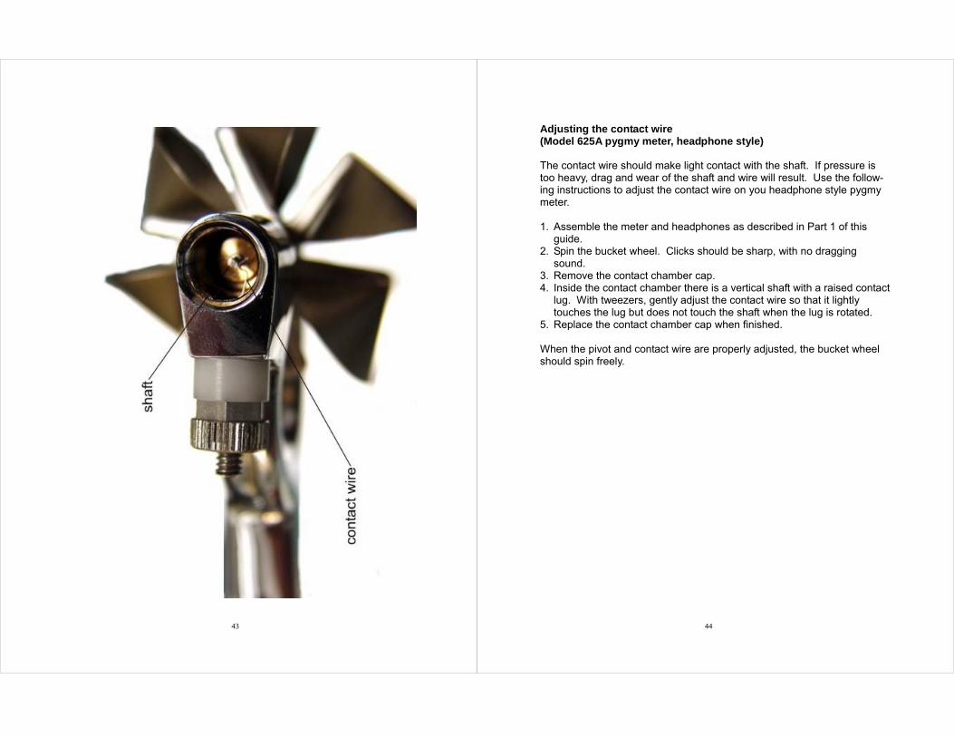
Adjusting the contact wire (Model 625A pygmy meter, headphone style) The contact wire should make light contact with the shaft. If pressure is too heavy, drag and wear of the shaft and wire will result. Use the follow-ing instructions to adjust the contact wire on you headphone style pygmy meter. 1. Assemble the meter and headphones as described in Part 1 of this
guide. 2. Spin the bucket wheel. Clicks should be sharp, with no dragging
sound. 3. Remove the contact chamber cap. 4. Inside the contact chamber there is a vertical shaft with a raised contact
lug. With tweezers, gently adjust the contact wire so that it lightly touches the lug but does not touch the shaft when the lug is rotated.
5. Replace the contact chamber cap when finished. When the pivot and contact wire are properly adjusted, the bucket wheel should spin freely.
45 46
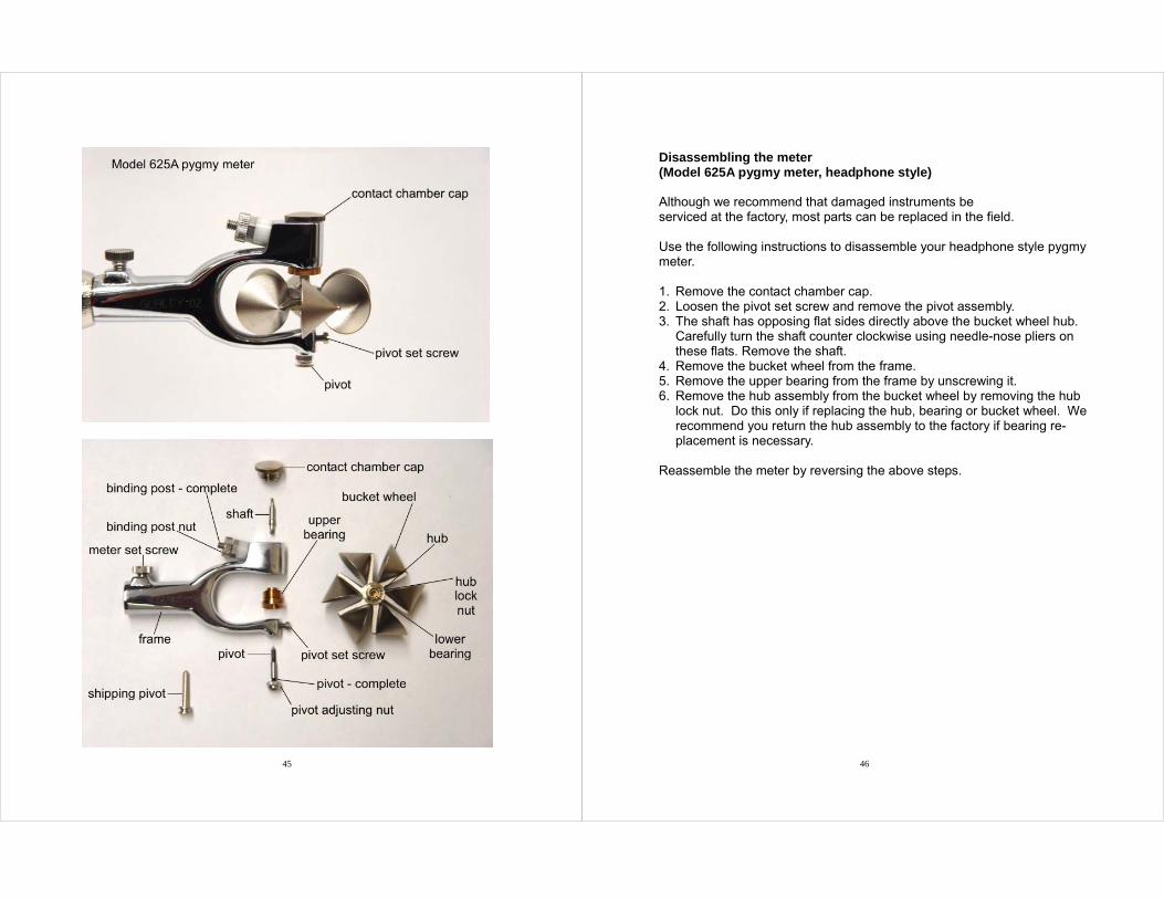
Disassembling the meter (Model 625A pygmy meter, headphone style) Although we recommend that damaged instruments be serviced at the factory, most parts can be replaced in the field. Use the following instructions to disassemble your headphone style pygmy meter. 1. Remove the contact chamber cap. 2. Loosen the pivot set screw and remove the pivot assembly. 3. The shaft has opposing flat sides directly above the bucket wheel hub.
Carefully turn the shaft counter clockwise using needle-nose pliers on these flats. Remove the shaft.
4. Remove the bucket wheel from the frame. 5. Remove the upper bearing from the frame by unscrewing it. 6. Remove the hub assembly from the bucket wheel by removing the hub
lock nut. Do this only if replacing the hub, bearing or bucket wheel. We recommend you return the hub assembly to the factory if bearing re-placement is necessary.
Reassemble the meter by reversing the above steps.
47 48
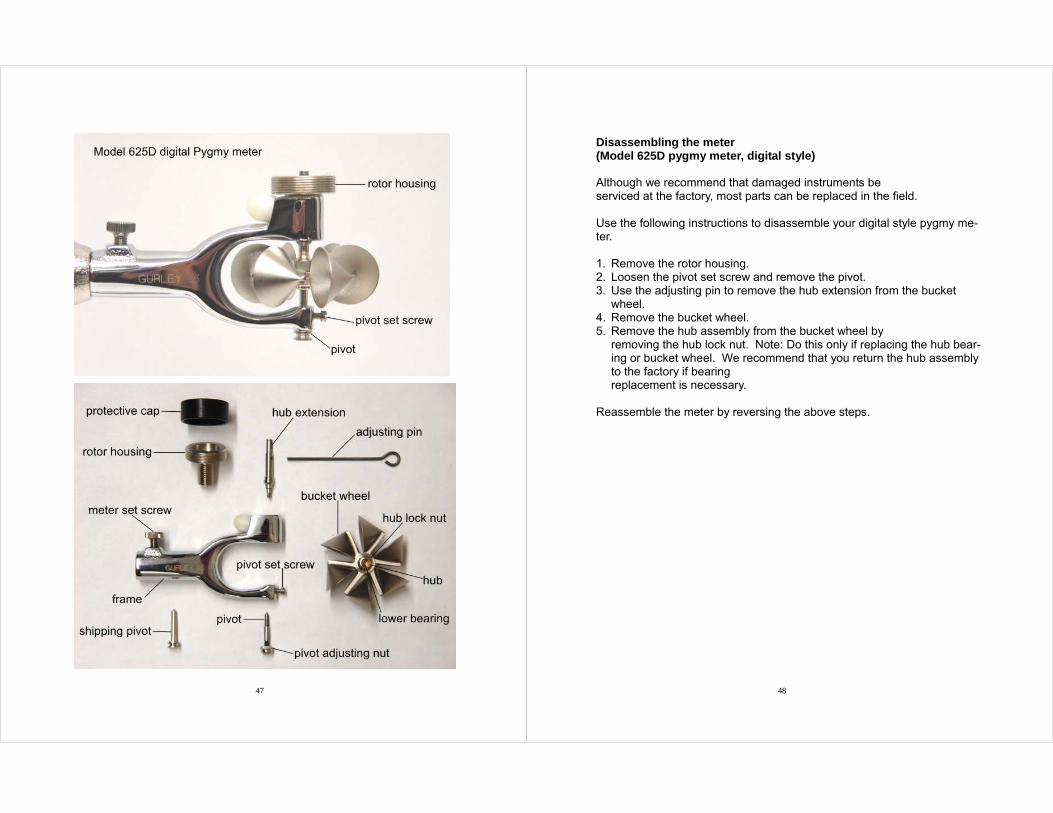
Disassembling the meter (Model 625D pygmy meter, digital style) Although we recommend that damaged instruments be serviced at the factory, most parts can be replaced in the field. Use the following instructions to disassemble your digital style pygmy me-ter. 1. Remove the rotor housing. 2. Loosen the pivot set screw and remove the pivot. 3. Use the adjusting pin to remove the hub extension from the bucket
wheel. 4. Remove the bucket wheel. 5. Remove the hub assembly from the bucket wheel by
removing the hub lock nut. Note: Do this only if replacing the hub bear-ing or bucket wheel. We recommend that you return the hub assembly to the factory if bearing replacement is necessary.
Reassemble the meter by reversing the above steps.

49 50
HEADPHONES Replacing the battery Use the following instructions to replace the battery in your headphones. 1. Disconnect the earphone cable from the suspension cable or the rod ca-
ble. 2. Remove the plastic earpiece cushion from the earpiece that does not have
the cable entering it. 3. Insert a small flathead screw driver in the groove on the right side of the
earpiece and gently pop the cover off the earpiece. Do not pull on the cover, or you may break the soldered connections.
4. Using the screw driver, gently pry the battery out of the battery holder. 5. Insert a new, type N battery in the battery holder. You may insert the bat-
tery in either direction. 6. Replace the earpiece cover by inserting the left side of the cover into its
grooves and then pressing the right side into place. 7. Replace the plastic earpiece cushion. 8. Connect the earphone cable to the suspension cable or the rod cable. Spinning the bucket wheel should now produce audible clicks in the head-phones.
51 52
Part 3 Using the Model 1100 Digital Flow Velocity Indicator The Model 1100 Digital Flow Velocity Indicator attaches to either your Price or pygmy meter to quickly give you accurate current measurements. This part of the guide contains three sections on how to use the Model 1100. The first section describes the panel of the Model 1100 and defines the function of each button. The second section describes the Model 1100’s self-test functions. The last section describes how to operate the Model 1100 in each of its three modes – automatic, averaging, and man-ual.
53 54
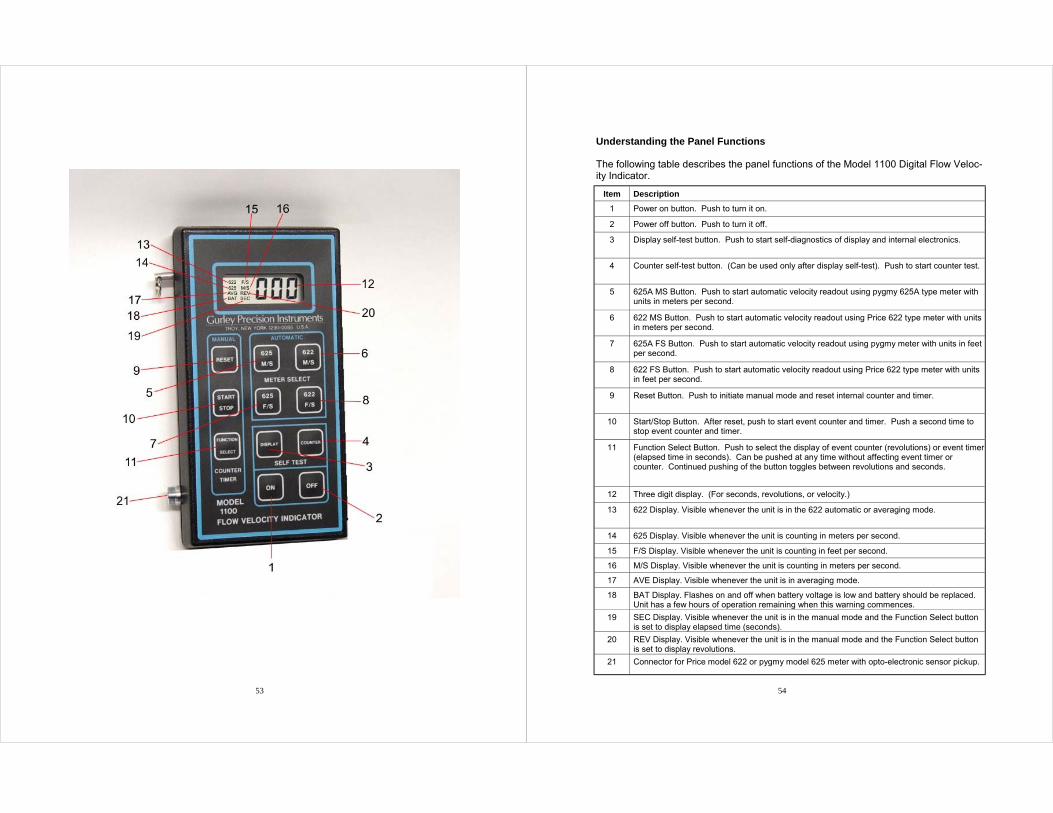
Understanding the Panel Functions The following table describes the panel functions of the Model 1100 Digital Flow Veloc-ity Indicator.
Item Description
1 Power on button. Push to turn it on.
2 Power off button. Push to turn it off.
3 Display self-test button. Push to start self-diagnostics of display and internal electronics.
4 Counter self-test button. (Can be used only after display self-test). Push to start counter test.
5 625A MS Button. Push to start automatic velocity readout using pygmy 625A type meter with units in meters per second.
6 622 MS Button. Push to start automatic velocity readout using Price 622 type meter with units in meters per second.
7 625A FS Button. Push to start automatic velocity readout using pygmy meter with units in feet per second.
8 622 FS Button. Push to start automatic velocity readout using Price 622 type meter with units in feet per second.
9 Reset Button. Push to initiate manual mode and reset internal counter and timer.
10 Start/Stop Button. After reset, push to start event counter and timer. Push a second time to stop event counter and timer.
11 Function Select Button. Push to select the display of event counter (revolutions) or event timer (elapsed time in seconds). Can be pushed at any time without affecting event timer or counter. Continued pushing of the button toggles between revolutions and seconds.
12 Three digit display. (For seconds, revolutions, or velocity.)
13 622 Display. Visible whenever the unit is in the 622 automatic or averaging mode.
14 625 Display. Visible whenever the unit is counting in meters per second.
15 F/S Display. Visible whenever the unit is counting in feet per second.
16 M/S Display. Visible whenever the unit is counting in meters per second.
17 AVE Display. Visible whenever the unit is in averaging mode.
18 BAT Display. Flashes on and off when battery voltage is low and battery should be replaced. Unit has a few hours of operation remaining when this warning commences.
19 SEC Display. Visible whenever the unit is in the manual mode and the Function Select button is set to display elapsed time (seconds).
20 REV Display. Visible whenever the unit is in the manual mode and the Function Select button is set to display revolutions.
21 Connector for Price model 622 or pygmy model 625 meter with opto-electronic sensor pickup.
55 56
Performing a self-test The Model 1100 Digital Flow Velocity Indicator has built-in diagnostics to ensure proper operation of the unit. The diagnostics are performed in two stages: (1) operation of micro-controller/display and (2) operation of signal conditioning/counter. Complete the following instructions to perform a self-test on your Model 1100. 1. Disconnect any metering unit (622D or 625D) from the Model 1100 Indi-
cator. 2. Press the ON button. Display will read 000. 3. Press the DISPLAY button to begin the first stage of the self-test.
NOTE: COUNTER button has no action until display button has been pressed and the unit has completed its sequence of test. After pressing DISPLAY button, each digit of the display will count from 0 to 9, beginning with the right digit, ending with the display at 999. Next, all of the display messages, except BAT, will be visible for approximately 3 seconds, then the display returns to 999.
4. If desired, self-test mode can be cancelled at this time to enter another mode. To do so, press the OFF button. To begin the second stage of the self-test, press the COUNTER button. The counter will now begin incrementing the display at a rate of one count per second.
5. Compare the display count rate against an accurate watch for the ap-propriate count rate. If they are in agreement, the Model 1100 has passed its diagnostics.
6. To leave this counting mode, press the OFF button. 7. If problems persist, try substituting a different meter unit, or replace the
battery. If the voltage of the battery is low, the BAT display message will flash on and off. At this point, the unit will still have a few hours of service left. However, failure to replace the battery will result in erratic or no operation of the unit. To replace the battery, remove the battery cover located on the rear of the Model 1100 case. Insert a new 9VDC battery and replace cover.
57
Operating the Model 1100 Automatic mode For quick and convenient readings of flow velocity, the Model 1100 pro-vides automatic velocity computation for the 622D and 625D meters in both feet per second and meters per second. To operate your Model 1100 in the automatic mode, use the following instructions. 1. Connect the Price 622D Meter (or pygmy 625D) to the Model 1100 Indi-
cator using the connector on the side of the Model 1100. 2. Press the ON button. 3. Press a meter select button once to indicate the type of
meter being used and the desired units (e.g. 622 MS or 625 FS). NOTE: After pressing the button, the display will go to 000 and the type of meter and units selected will be shown on the display.
4. Every four seconds the display will be updated showing the flow veloc-ity.
Averaging Mode An averaging feature is incorporated into the Model 1100 to smooth out flow velocity variations. To operate your Model 1100 in the averaging mode, use the following instructions. 1. Connect the price 622D Meter (or pygmy 625D) to the Model 1100 Indi-
cator using the connector on the side of the Model 1100. 2. Press the ON button. Display will read 000. 3. Press a meter select button twice to indicate the type of meter being
used and the desired units (e.g., 622 FS or 625A MS). NOTE: After pressing the button twice, the display will go to 000 and the type of meter, units selected, and AVE will be shown on the display.
4. Every sixteen seconds the display will be updated showing the flow ve-locity averaged over four of the standard automatic samples. NOTE: Press the meter select button again to tog-gle the meter between standard and average modes.
58
Manual mode Where longer sampling periods are needed due to very low velocity, or if a higher degree of accuracy is required, we recommend that you use the manual operating mode and the rating tables to determine the flow rate. To operate your Model 1100 in the manual mode, use the following instructions. 1. Connect the Price 622D meter (or pygmy 625D) to the Model 1100 Indi-
cator using the connector on the side of the Model 1100. 2. Press ON button. 3. Press RESET button to enter manual mode of operation. 4. When ready to begin counting revolutions and elapsed time, press the
START/STOP button once .* NOTE: At this time the indicator will begin counting revolutions and elapsed time. The display will show the elapsed time in seconds. To display the number of revolutions, press the FUNCTION SELECT button once. The display will show REV and the number of complete revolutions counted. Pressing the FUNCTION SELECT button causes the display to toggle between elapsed time and revolutions.
5. To stop counting and freeze elapsed time, press the START/STOP but-ton a second time. The elapsed time and number of revolutions will be stored and can be read by using the FUNCTION SELECT button to toggle between elapsed time and revolutions. Determine the flow rate using this information and the rating table included with the meter.
6. To take another measurement, press the RESET button and repeat steps 4 and 5.
___________________ * The Model 1100 will begin actual counting of rotations and seconds when the meter-ing unit has rotated past the first input pulse.

59 60
Part 4 Converting Headphone Style Meters to Digital Headphone style Price and pygmy meters can be converted to digital me-ters using conversion kits available from Gurley.
61 62
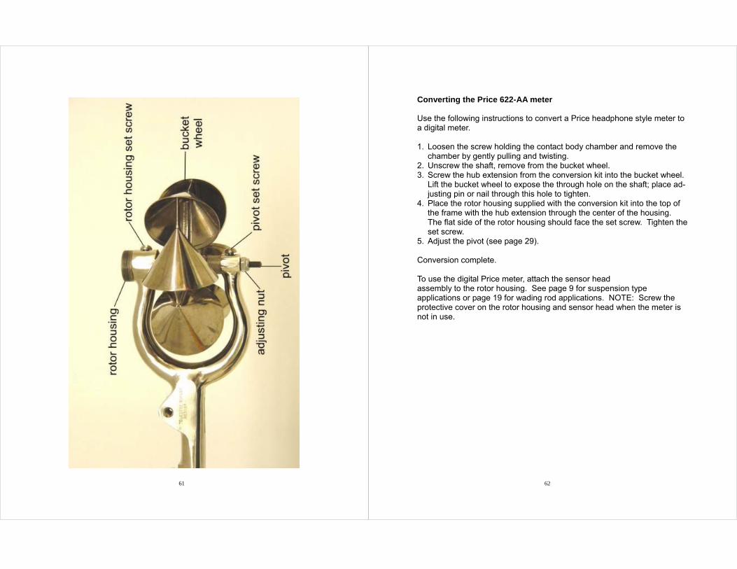
Converting the Price 622-AA meter Use the following instructions to convert a Price headphone style meter to a digital meter. 1. Loosen the screw holding the contact body chamber and remove the
chamber by gently pulling and twisting. 2. Unscrew the shaft, remove from the bucket wheel. 3. Screw the hub extension from the conversion kit into the bucket wheel.
Lift the bucket wheel to expose the through hole on the shaft; place ad-justing pin or nail through this hole to tighten.
4. Place the rotor housing supplied with the conversion kit into the top of the frame with the hub extension through the center of the housing. The flat side of the rotor housing should face the set screw. Tighten the set screw.
5. Adjust the pivot (see page 29). Conversion complete. To use the digital Price meter, attach the sensor head assembly to the rotor housing. See page 9 for suspension type applications or page 19 for wading rod applications. NOTE: Screw the protective cover on the rotor housing and sensor head when the meter is not in use.
63 64
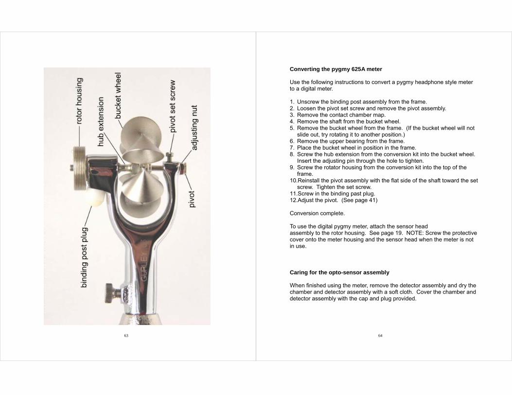
Converting the pygmy 625A meter Use the following instructions to convert a pygmy headphone style meter to a digital meter. 1. Unscrew the binding post assembly from the frame. 2. Loosen the pivot set screw and remove the pivot assembly. 3. Remove the contact chamber map. 4. Remove the shaft from the bucket wheel. 5. Remove the bucket wheel from the frame. (If the bucket wheel will not
slide out, try rotating it to another position.) 6. Remove the upper bearing from the frame. 7. Place the bucket wheel in position in the frame. 8. Screw the hub extension from the conversion kit into the bucket wheel.
Insert the adjusting pin through the hole to tighten. 9. Screw the rotator housing from the conversion kit into the top of the
frame. 10.Reinstall the pivot assembly with the flat side of the shaft toward the set
screw. Tighten the set screw. 11.Screw in the binding past plug. 12.Adjust the pivot. (See page 41) Conversion complete. To use the digital pygmy meter, attach the sensor head assembly to the rotor housing. See page 19. NOTE: Screw the protective cover onto the meter housing and the sensor head when the meter is not in use. Caring for the opto-sensor assembly When finished using the meter, remove the detector assembly and dry the chamber and detector assembly with a soft cloth. Cover the chamber and detector assembly with the cap and plug provided.
65 66
Part 5 Repair Parts Specifications and part numbers subject to change without notice. WADING ROD SETS
WADING ROD PARTS AND ACCESSORIES
Number Description 627E 627M 627F 299-309 299-309-2 299-309-3 299-309-5 299-309-6
English rod set, Price and pygmy meter – 8 feet Metric rod set, Price and pygmy meter – 2 feet English rod set, Price meter – 6 feet English top setting rod – 4 feet English top setting rod – 6 feet English top setting rod – 8 feet Metric top setting rod – 1 meter Metric top setting rod – 2 meters
All 627 rod sets include: 233-17 case, 24674 double end hanger and ap-propriate wading rod base.
Number Description Page AXO4239 427 233-71 24674 28962 32963 32956 32957 32958
Plastic cable clips (set of 8) Binding post Canvas case Double-end hanger Rod base – Price or pygmy 24” intermediate section ½ meter intermediate section ½ meter bottom section – Price or pygmy 24” Bottom section – Price or pygmy
19 15
15 15
67
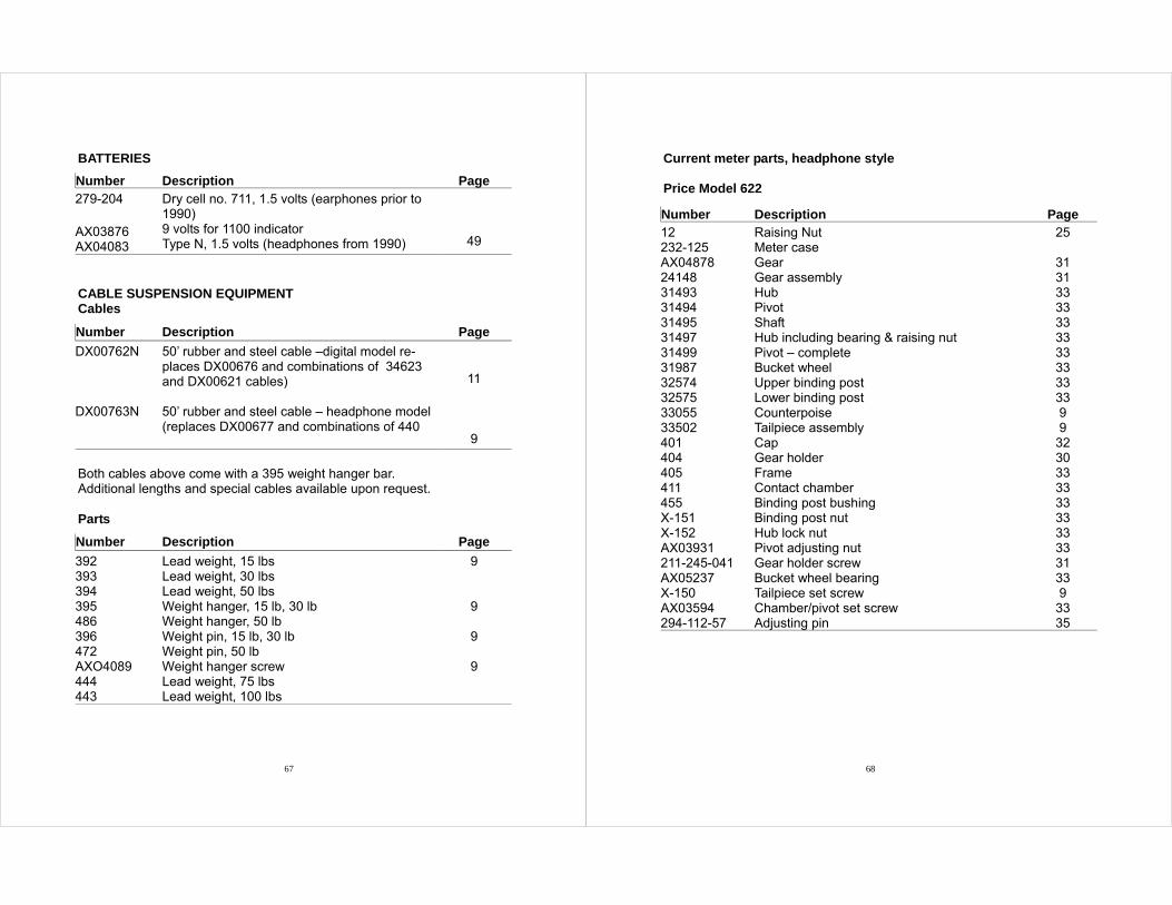
BATTERIES
CABLE SUSPENSION EQUIPMENT Cables
Both cables above come with a 395 weight hanger bar. Additional lengths and special cables available upon request. Parts
Number Description Page 279-204 AX03876 AX04083
Dry cell no. 711, 1.5 volts (earphones prior to 1990) 9 volts for 1100 indicator Type N, 1.5 volts (headphones from 1990)
49
Number Description Page
DX00762N DX00763N
50’ rubber and steel cable –digital model re-places DX00676 and combinations of 34623 and DX00621 cables) 50’ rubber and steel cable – headphone model (replaces DX00677 and combinations of 440
11
9
Number Description Page
392 393 394 395 486 396 472 AXO4089 444 443
Lead weight, 15 lbs Lead weight, 30 lbs Lead weight, 50 lbs Weight hanger, 15 lb, 30 lb Weight hanger, 50 lb Weight pin, 15 lb, 30 lb Weight pin, 50 lb Weight hanger screw Lead weight, 75 lbs Lead weight, 100 lbs
9
9
9
9
68
Current meter parts, headphone style Price Model 622
Number Description Page 12 232-125 AX04878 24148 31493 31494 31495 31497 31499 31987 32574 32575 33055 33502 401 404 405 411 455 X-151 X-152 AX03931 211-245-041 AX05237 X-150 AX03594 294-112-57
Raising Nut Meter case Gear Gear assembly Hub Pivot Shaft Hub including bearing & raising nut Pivot – complete Bucket wheel Upper binding post Lower binding post Counterpoise Tailpiece assembly Cap Gear holder Frame Contact chamber Binding post bushing Binding post nut Hub lock nut Pivot adjusting nut Gear holder screw Bucket wheel bearing Tailpiece set screw Chamber/pivot set screw Adjusting pin
25
31 31 33 33 33 33 33 33 33 33 9 9
32 30 33 33 33 33 33 33 31 33 9
33 35
69
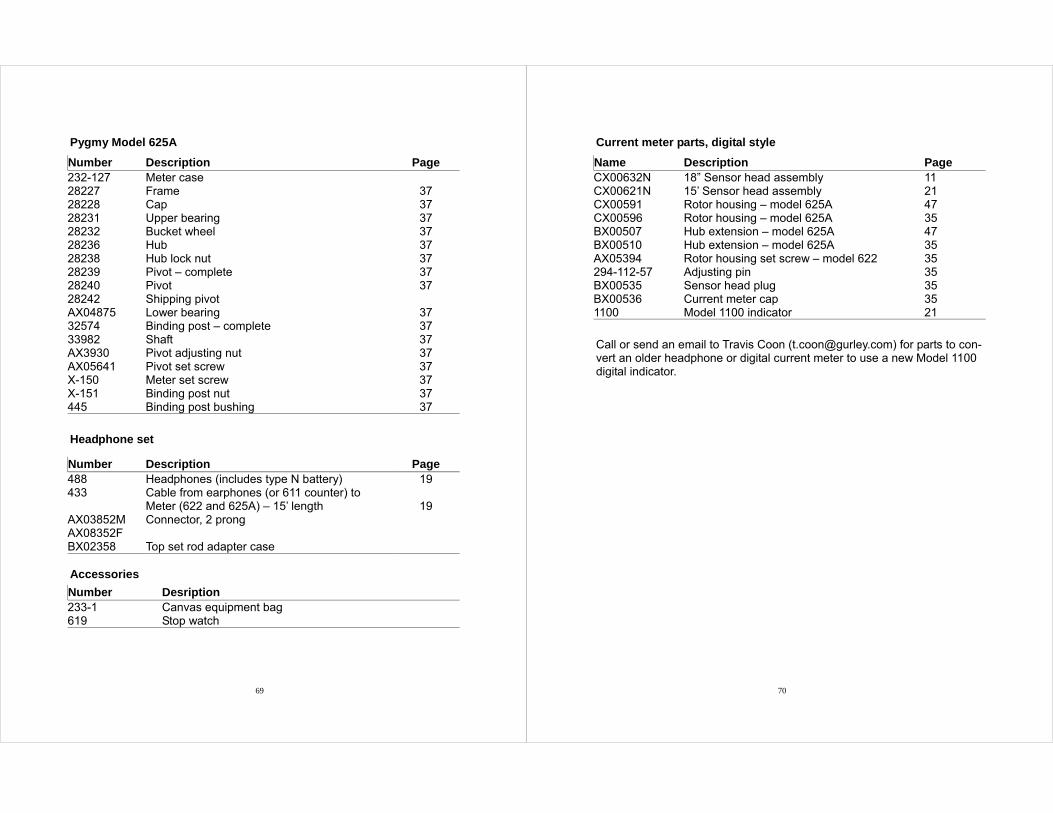
Pygmy Model 625A
Headphone set
Accessories
Number Description Page 232-127 28227 28228 28231 28232 28236 28238 28239 28240 28242 AX04875 32574 33982 AX3930 AX05641 X-150 X-151 445
Meter case Frame Cap Upper bearing Bucket wheel Hub Hub lock nut Pivot – complete Pivot Shipping pivot Lower bearing Binding post – complete Shaft Pivot adjusting nut Pivot set screw Meter set screw Binding post nut Binding post bushing
37 37 37 37 37 37 37 37
37 37 37 37 37 37 37 37
Number Description Page 488 433 AX03852M AX08352F BX02358
Headphones (includes type N battery) Cable from earphones (or 611 counter) to Meter (622 and 625A) – 15’ length Connector, 2 prong Top set rod adapter case
19
19
Number Desription 233-1 619
Canvas equipment bag Stop watch
70
Current meter parts, digital style
Call or send an email to Travis Coon ([email protected]) for parts to con-vert an older headphone or digital current meter to use a new Model 1100 digital indicator.
Name Description Page CX00632N CX00621N CX00591 CX00596 BX00507 BX00510 AX05394 294-112-57 BX00535 BX00536 1100
18” Sensor head assembly 15’ Sensor head assembly Rotor housing – model 625A Rotor housing – model 625A Hub extension – model 625A Hub extension – model 625A Rotor housing set screw – model 622 Adjusting pin Sensor head plug Current meter cap Model 1100 indicator
11 21 47 35 47 35 35 35 35 35 21