operation and maintenance c10 series transmission · pdf fileshifting instructions pneumatic...
TRANSCRIPT

Read through the safety information andoperating instructions carefully beforeusing your Waterous Fire Pump.
Table of ContentsSafety Information 2. . . . . . . . . . . . . . . . . . . . . . . . . . . . . .Introduction 3. . . . . . . . . . . . . . . . . . . . . . . . . . . . . . . . . . . . . . . . . . . .
General Description for Transmissions 3. . . . . . . . . .General Description for Accessories 3. . . . . . . . . . . . .Shifting Instructions 4. . . . . . . . . . . . . . . . . . . . . . . . . . . .Pneumatic Pump Shift 4. . . . . . . . . . . . . . . . . . . . . . . . . . .Pneumatic Shift Manual Override 5. . . . . . . . . . . . . . . . . .Maintenance 6. . . . . . . . . . . . . . . . . . . . . . . . . . . . . . . . . . .Indicating Lights Operation 6. . . . . . . . . . . . . . . . . . . . . . .Tachometer Readings 6. . . . . . . . . . . . . . . . . . . . . . . . . . .Fluid Levels 7. . . . . . . . . . . . . . . . . . . . . . . . . . . . . . . . . . . .Shift Linkage 7. . . . . . . . . . . . . . . . . . . . . . . . . . . . . . . . . . . .Pump Shift Troubleshooting Guide 8. . . . . . . . . . . . . . . . .Pump Transmission Shift Component Inspection 11. . .
Illustrations1. C10 Transmission Mounted on an S100 Series Pump 32. C10 Transmission Mounted on a Midship Pump 3. . . . .3. Pneumatic Shift Manual Override 5. . . . . . . . . . . . . . . . . .
C10 Series Transmission
Waterous Company 125 Hardman Avenue South, South St. Paul, Minnesota 55075 USA (651) 450-5000Instructions subject to change without notice.
Visit us at www.waterousco.com
Section
2208Form No.
F-1031Issue Date
09/27/02Rev. Date
09/12/12C10 Series Transmission
Operation and Maintenance

F-1031, Section 2208 Page 2 of 12
Safety Information
Read through the safety information and operating instructions before using your Waterous FirePump.
WARNING!
Death or serious personal injury might occur if properoperating procedures are not followed. The pump op-erator, as well as individuals connecting supply or dis-charge hoses to the apparatus must be familiar withthese pump operating instructions as well as otheroperating instructions and manuals for the apparatus,water hydraulics and component limitation.
WARNING!
Unexpected Truck MovementMay result in serious personal injury or deathFailure to properly shift transmission in accordance tothe transmission operating instructions may result inunexpected truck movement which may result inserious personal injury or death.
WARNING!
If the truck attempts to move, reduce engine speed toidle. Put truck transmission in NEUTRAL and repeatshifting instructions.

F-1031, Section 2208 Page 3 of 12
IntroductionThe Waterous C10 transmission, constructed of high-strength aluminum transmits power from the truck's auto-matic transmission either to the fire pump or to the driveaxle of the truck.
This instruction is divided into four sections:• General Description for Transmissions
• General Description for Accessories
• Shifting Instructions• Maintenance Instructions
General Description for TransmissionsThe bearings and drive chain are lubricated by a splashand passive lubrication system. Lubrication is accom-plished when spray from the chain collects in a reservoirin the top of the case. The lubricant flows out of the reser-voir, through a hose and onto the inside surface of thechain. This ensures all pivoting components of the chainreceive lubrication.An electronic tachometer connection protrudes from thetachometer housing at a 45° angle. This tachometer pick-up senses the drive shaft speed.The shift mechanism within the transmission consists of asliding internally-toothed collar which is always in engage-ment with an externally-toothed section of the drive shaft.A fork shifts the collar either to engage it with teeth on thedrive sprocket hub (PUMP) or to engage it with the teethon the coupling shaft (ROAD). When in PUMP position,the shift collar transmits power from the drive shaftthrough the drive sprocket and the chain to the drivensprocket. The coupling shaft remains stationary. When inROAD position, the shift collar transmits power directlyfrom the drive shaft through the coupling shaft to the truckpropeller shaft and drive axle(s). In this position, the pumpdrive and driven sprockets remain stationary while thedrive shaft rotates.Three shift indicator lights are furnished. Two aremounted in the cab and the other is mounted on the oper-ators panel. These lights indicate to the operators that theshift has been completed into PUMP position and thetruck transmission is in pumping gear.
Figure 1. C10 Transmission Mounted on an S100 Pump
Figure 2. C10 Transmission Mounted on a Midship Pump
IL2740
General Description for AccessoriesThe pneumatic shift assembly permits fast, positive shift-ing without leaving the cab. A two-position control,mounted on the instrument panel in the cab activates theshift unit.
The pneumatic shift is equipped with a complete set oflights that indicate when the shift has been fully completedto PUMP and the truck transmission is in pumping gear.

F-1031, Section 2208 Page 4 of 12
Shifting InstructionsPneumatic Shift
Two series of Allison automatic transmissions are com-monly used in fire trucks. Each series is available with theshift patterns controlled hydraulically or both electronicallyand hydraulically. This later type is commonly referred toas the ATEC transmission.In each automatic transmission, either the non-ATEC orthe ATEC, certain sequences must occur in proper orderafter the pump shift control is moved to either PUMP orROAD position.Split shaft pump transmissions, automatic transmissionsand engines will vary in operation due to manufacturingtolerances, lubrication temperature, etc. This variance ineach may or may not affect the ease of completing a fullshift into either PUMP or ROAD. Operator training andexperience in shifting procedures is a requirement to be-coming skilled in a smooth, complete shift into eitherPUMP or ROAD.When the pump shift is activated, the operator mayhear a noise associated with the movement of theshift unit. This does NOT mean that the shift has beencompleted.After the shift to pump operation is completed, the greenPUMP ENGAGED and OK TO PUMP lights in the cabmust be on before leaving the cab to operate the pumpfrom the operators panel. DO NOT LEAVE THE CAB IFTHE GREEN PUMP ENGAGED AND OK TO PUMPLIGHTS ARE NOT ON.Some truck builders may install a manual override for theelectric or pneumatic pump shift. The controls are normal-ly installed from the pump transmission to the operatorspanel.
WARNING!
Unexpected Truck Movement.May result in serious personal injury ordeath.Failure to properly shift transmission in accor-dance to the transmission operating instructionsmay result in unexpected truck movement whichmay result in serious personal injury or death.
Shift to PUMP as follows:1. Bring truck to complete stop.2. Reduce engine to idle speed, put truck transmission
into NEUTRAL.3. Set truck parking brake.4. Move pump shift control to PUMP position.NOTE: Green PUMP ENGAGED light may not illumi-nate.5. Shift truck transmission into pumping gear (DRIVE).
CAUTIONShifting truck transmission into pumping gear(DRIVE) above engine idle speed may causedamage to the equipment.
6. Green PUMP ENGAGED and OK TO PUMP lightsshould be on.
CAUTIONIf green PUMP ENGAGED and OK TO PUMPlight are not on, momentarily shift truck transmis-sion from pumping gear (DRIVE) to NEUTRAL,then REVERSE, then NEUTRAL, then back intopumping gear (DRIVE). Lights should be on. Iflights are not on, repeat procedure.
7. Increase engine speed above idle and hold for a fewseconds. Watch speedometer to make sure it showssome value of road speed.NOTE: Some fire trucks have a speedometer thatwill not show a value of road speed in a stationaryposition.
WARNING!
If the truck attempts to move, reduce enginespeed to idle. Put truck transmission in NEU-TRAL and repeat shifting instructions.
8. After leaving truck cab, block wheels using wheelchocks.
9. To confirm that the pump is engaged:S THROTTLE READY light on operator's panel
is illuminated.S Pump discharge pressure registers on gages.S Other safety interlocks are activated.
Shift to ROAD as follows:1. With engine speed at idle, put truck transmission in
NEUTRAL.2. When speedometer slows to zero, move pump shift
control to ROAD position.3. Engage truck transmission (DRIVE).
CAUTIONIf you hear a loud grinding noise when you at-tempt to move the truck, the shift to ROAD hasnot been completed. Shift into NEUTRAL, wait forgrinding noise to stop and re-engage truck trans-mission.
If grinding is a common occurrence after Step 3 is per-formed, it may be prevented by shifting the truck transmis-sion into NEUTRAL, then to REVERSE, back to NEU-TRAL and finally to DRIVE.4. After shifting the truck transmission to DRIVE, release
the parking brake and move the vehicle forward toconfirm a shift to ROAD has been completed.

F-1031, Section 2208 Page 5 of 12
Pneumatic Shift Manual OverrideTwo series of Allison automatic transmissions are com-monly used in fire trucks. Each series is available with theshift patterns controlled hydraulically or both electronicallyand hydraulically. This later type is commonly referred toas the ATEC transmission.In each automatic transmission, either the non-ATEC orthe ATEC, certain sequences must occur in proper orderafter the pump shift control is moved to either PUMP orROAD position.Split shaft pump transmissions, automatic transmissionsand engines will vary in operation due to manufacturingtolerances, lubrication temperature, etc. This variance ineach may or may not affect the ease of completing a fullshift into either PUMP or ROAD. Operator training andexperience in shifting procedures is a requirement to be-coming skilled in a smooth, complete shift into eitherPUMP or ROAD.When the pump shift is activated, the operator mayhear a noise associated with the movement of theshift unit. This does NOT mean that the shift has beencompleted.After the shift to pump operation is completed, the greenPUMP ENGAGED and OK TO PUMP lights in the cabmust be on before leaving the cab to operate the pumpfrom the operators panel. DO NOT LEAVE THE CAB IFTHE GREEN PUMP ENGAGED AND OK TO PUMPLIGHTS ARE NOT ON.If the vehicle builder has provided a means to manuallyoverride the pneumatic pump shift, the override controlwill be located at the operators panel or in the cab. Theoverride control will consist of a rod to the panel or acable or rod mechanism to the inside of the cab. The rodor cable will be attached to the shift arm on the pumptransmission.NOTE: This instruction is written based on an over-ride control rod directed to the operators panel fromthe short arm of the lever on the pump transmission.Other rod or cable arrangements may require reversalof stated action to accomplish the desired shift.Figure 3. Pneumatic Shift Manual Override
IL1011Rod to side of truck
Rod or cable to cab
If the pump transmission is equipped with an override,shifting manually is done as follows:It is recommended that this procedure be performed usingtwo people; one person in the cab and one at the overridecontrol position.
WARNING!
Unexpected Truck Movement.May result in serious personal injury ordeath.Failure to properly shift transmission in accor-dance to the transmission operating instructionsmay result in unexpected truck movement whichmay result in serious personal injury or death.
Shift to PUMP as follows:1. Bring truck to complete stop.2. Reduce engine to idle speed, put truck transmission in
NEUTRAL.3. Set truck parking brake.4. Move in-cab pump shift control into the CENTER posi-
tion.5. Push manual shift control rod in for PUMP position.6. Move the in-cab pump shift control into the PUMP
position.7. Green PUMP ENGAGED light should be on.
CAUTIONIf green PUMP ENGAGED light is not on, mo-mentarily shift truck transmission into REVERSEwhile keeping pressure on the manual shift rod.Return to NEUTRAL. Green PUMP ENGAGEDlight should be on.
8. Shift truck transmission into pumping gear (DRIVE).
CAUTIONShifting truck transmission into pumping gearabove engine idle speed may cause damage tothe equipment.
9. Green OK TO PUMP light should be on.
10. Increase engine speed above idle and hold for a fewseconds. Watch speedometer to make sure it showssome value of road speed.
NOTE: Some fire trucks have a speedometer that willnot show a value of road speed in a stationary posi-tion.
WARNING!
If the truck attempts to move, reduce enginespeed to idle. Put truck transmission in NEU-TRAL and repeat shifting instructions.
F-1031, Section 2208 Page 6 of 12
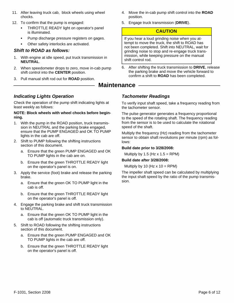
11. After leaving truck cab, block wheels using wheelchocks.
12. To confirm that the pump is engaged:S THROTTLE READY light on operator's panel
is illuminated.S Pump discharge pressure registers on gages.S Other safety interlocks are activated.
Shift to ROAD as follows:1. With engine at idle speed, put truck transmission in
NEUTRAL.
2. When speedometer drops to zero, move in-cab pumpshift control into the CENTER position.
3. Pull manual shift rod out for ROAD position.
4. Move the in-cab pump shift control into the ROADposition.
5. Engage truck transmission (DRIVE).
CAUTIONIf you hear a loud grinding noise when you at-tempt to move the truck, the shift to ROAD hasnot been completed. Shift into NEUTRAL, wait forgrinding noise to stop and re-engage truck trans-mission, while keeping pressure on the manualshift control rod.
6. After shifting the truck transmission to DRIVE, releasethe parking brake and move the vehicle forward toconfirm a shift to ROAD has been completed.
Maintenance
Indicating Lights OperationCheck the operation of the pump shift indicating lights atleast weekly as follows:NOTE: Block wheels with wheel chocks before begin-ning.1. With the pump in the ROAD position, truck transmis-
sion in NEUTRAL and the parking brake engaged,ensure that the PUMP ENGAGED and OK TO PUMPlights in the cab are off.
2. Shift to PUMP following the shifting instructionssection of this document.a. Ensure that the green PUMP ENGAGED and OK
TO PUMP lights in the cab are on.
b. Ensure that the green THROTTLE READY lighton the operator's panel is on.
3. Apply the service (foot) brake and release the parkingbrake.a. Ensure that the green OK TO PUMP light in the
cab is off.
b. Ensure that the green THROTTLE READY lighton the operator's panel is off.
4. Engage the parking brake and shift truck transmissionto NEUTRAL.a. Ensure that the green OK TO PUMP light in the
cab is off (automatic truck transmission only).5. Shift to ROAD following the shifting instructions
section of this document.a. Ensure that the green PUMP ENGAGED and OK
TO PUMP lights in the cab are off.
b. Ensure that the green THROTTLE READY lighton the operator's panel is off.
Tachometer ReadingsTo verify input shaft speed, take a frequency reading fromthe tachometer sensor.The pulse generator generates a frequency proportionalto the speed of the rotating shaft. The frequency readingfrom the sensor is to be used to calculate the rotationalspeed of the shaft.Multiply the frequency (Hz) reading from the tachometersensor to obtain shaft revolutions per minute (rpm) as fol-lows:Build date prior to 3/28/2008:
Multiply by 1.5 (Hz x 1.5 = RPM)Build date after 3/28/2008:
Multiply by 10 (Hz x 10 = RPM)The impeller shaft speed can be calculated by multiplyingthe input shaft speed by the ratio of the pump transmis-sion.

F-1031, Section 2208 Page 7 of 12
Fluid Levels1. Check fluid level monthly by removing fluid level plug
at rear of case. The fluid should be level with bottomof hole.
A sight plug is also provided for this purpose, and the fluidlevel should be visible thru this plug.
CAUTIONIf fluid level is low, locate source of leak andrepair. If fluid level is high, loosen drain plug untilfluid drops to proper level. If excessive waterdrains out, change fluid and determine source ofwater leakage, and repair.
NOTE: Fluid temperature should not exceed 250° foran extended period of time or premature seal wearand damage may occur.
Fluid can be added thru the fluid level hole or by removingthe breather and adding fluid thru this opening. Any typeof automatic transmission fluid (ATF) can be used.2. Change fluid twice per year or after each 100 hours of
operation, whichever comes first. Clean the breatherand magnetic drain plug thoroughly whenever thetransmission fluid is changed.
Amount required if system is drained and refilled12 quarts (approximately)
Shift LinkagePeriodically check all shift linkage for freedom of move-ment and clean as necessary.

F-1031, Section 2208 Page 8 of 12
Pump Shift Troubleshooting GuideIt is important to know what to do if you experience shifting problems with your pump. This troubleshooting guide will helpyou diagnose, isolate and correct problems as they are encountered.For problems not covered in this guide, or for additional technical assistance, please contact the Waterous ServiceDepartment.
Problem
Is the chassistransmission
in DRIVE(automatic) or
in its pumpgear (Manual)?
Possible Cause
Recommended Action
Pneumatic Shift Electric Shift
Pump won't engage
Pump shift control is in thePUMP position and:
1. No lights or Red lightstays on or flashed (units
built prior to 1991).
or
2. PUMP ENGAGED lightdoes not come on (units
built 1991 or newer).
No Butt-tooth condition Butt-tooth condition
Place the chassistransmission in Drive(automatic) or in its
pumping gear (manual).
Yes
Malfunctioning shiftindicating switch or
switch out ofadjustment
Malfunctioning shiftindicating switch or
switch out ofadjustment
Replace or adjust theshift indicating switch or
bracket.
Manual overridelinkage binding
Manual overridelinkage binding
Repair or replace toeliminate binding.
Excessive drivelinetorque
Excessive drivelinetorque
Shift the chassistransmission into
REVERSE momentarily,then NEUTRAL, then
DRIVE.----------
Consider reducingengine idle speed.
----------It may be necessary to
contact the chassistransmission
manufacturer forassistance.
Low air pressure topneumatic shift unit
(80 psi min.)--
Allow air pressure tobuild in the system,
repair any leaks in thesystem.
Leaking pneumaticshift unit. -- Repair or replace
pneumatic shift unit.
Malfunctioning aircontrol valve -- Repair or replace air
control valve.
-- No power to shift unit. Repair as needed torestore power supply.
--
Failed shift motor -check current draw,
should be 20A atstartup and 10A
through the cycle.
Replace the shift motor.
--
Failed shift unit - unithas power and drawscorrect amperage but
will not activate.
Repair or replace theelectric shift unit.

F-1031, Section 2208 Page 9 of 12
ProblemIs the PUMPENGAGEDlight on?
Possible CauseRecommended Action
Pneumatic Shift Electric Shift
Pump will not engageand there is a grindingnoise emanating from
the pump transmission.
Pump shift control is in thePUMP position and:
1. The chassistransmission is in DRIVE
(automatic) or in itspumping gear (manual).
or
2. The chassistransmission is in
NEUTRAL.
No
Manual overridelinkage binding.
Manual overridelinkage binding.
Repair or replace toeliminate binding.
Excessive drivelinetorque.
Excessive drivelinetorque.
Shift the chassistransmission into
REVERSE momentarily,then NEUTRAL, then
DRIVE.----------
Consider reducingengine idle speed.
----------It may be necessary to
contact the chassistransmission
manufacturer forassistance.
Low or no air pressureto pneumatic shift unit
(80 psi min.)--
Allow air pressure tobuild in the system,
repair any leaks in thesystem.
--Weak shift unit or
non-Wateroussupplied shift unit.
Replace shift unit with ahigh-torque shift unit
provided by Waterous.Damage to internalpump transmission
shifting components.
Damage to internalpump transmission
shifting components.
See pump transmissioninspection instructions.
Yes
Shift indicating switchis out of adjustment or
its bracket isdamaged.
Malfunctioning shiftindicating switch or
switch out ofadjustment.
Adjust the shiftindicating switch orreplace the bracket.
Damage to internalpump transmission
shifting components.
Damage to internalpump transmission
shifting components.
See pump transmissioninspection instructions.
Chassis engine stallsafter placing the pumpshift control in PUMP
and placing the chassistransmission in DRIVE
(automatic) or in itspumping gear (manual).
No
Pump transmissionhas not shifted out of
ROAD due toexcessive driveline
torque.
Pump transmissionhas not shifted out of
ROAD due toexcessive driveline
torque.
Shift the chassistransmission into
REVERSE momentarily,then NEUTRAL, then
DRIVE.----------
Consider reducingengine idle speed.
----------It may be necessary to
contact the chassistransmission
manufacturer forassistance.
Damage to internalpump transmission
shifting components.
Damage to internalpump transmission
shifting components.
See pump transmissioninspection instructions.
Yes Seized fire pump. Seized fire pump. Repair fire pump asnecessary.

F-1031, Section 2208 Page 10 of 12
Problem
Is the chassistransmission
in DRIVE(automatic) or
in its pumpgear (Manual)?
Possible Cause
Recommended Action
Pneumatic Shift Electric Shift
PUMP ENGAGED light ison but OK TO PUMP
light will not illuminate.
(Units built 1991 andlater)
No Chassis transmissionnot in the proper gear.
Chassis transmissionnot in the proper gear.
Place the chassistransmission in DRIVE
(automatic) or in itspumping gear (manual).
Yes
Parking brake is notapplied.
Parking brake is notapplied. Apply the parking brake.
Problem with highrange lockup or safety
interlock systems.
Problem with highrange lockup or safety
interlock systems.
Contact the apparatusmanufacturer or
consideralternative wiring forhigh range lockup.
Problem with chassistransmission or
transmissionelectronic control unit.
Problem with chassistransmission or
transmissionelectronic control unit.
Contact the chassistransmission
manufacturer forassistance.
Problem
Is the Pumptransmissionshift arm incontact with
the shiftindicatingswitch?
Possible Cause
Recommended Action
Pneumatic Shift Electric Shift
Pump shift control is inthe ROAD position, butthe PUMP ENGAGEDand/or OK TO PUMP
lights stay on.
Note: Chassis engine maystall if the chassis
transmission is placed inDRIVE (automatic) or in
its pumping gear(manual).
No Shift indicating switchstuck closed.
Shift indicating switchstuck closed.
Replace the shiftindicating switch.
Yes
Locking arm assemblyis installed backwards
inside pumptransmission (the shift
arm should moveaway from the shift
indicating switch whenshifting to pump).
Locking arm assemblyis installed backwards
inside pumptransmission (the shift
arm should moveaway from the shift
indicating switch whenshifting to pump).
Remove locking armassembly and re-install
correctly.

F-1031, Section 2208 Page 11 of 12
ProblemPossible Cause
Recommended ActionPneumatic Shift Electric Shift
Pump shift control is inthe ROAD position and
grinding sounds areheard emanating from the
pump transmission.
Chassis transmission is ingear when shifting pump.
Chassis transmission is ingear when shifting pump.
Place the chassistransmission in NEUTRAL
before shifting pumptransmission.
Butt-tooth condition -chassis transmission is in
REVERSE.
Butt-tooth condition -chassis transmission is in
REVERSE.
Place the chassistransmission in DRIVE aftershifting pump transmission
to ROAD.
Excessive driveline torqueand/or rotation.
Excessive driveline torqueand/or rotation.
Ensure the driveline is notrotating before shifting to
ROAD.----------
Consider reducing engineidle speed.
----------It may be necessary to
contact the chassistransmission manufacturer
for assistance.
Damage to pumptransmission shifting
components.
Damage to pumptransmission shifting
components.
See pump transmissioninspection instructions.
Manual pump shiftoverride control cannot
be moved by hand(electric or pneumatic
shift functions properly).
Air pressure present onpneumatic shift piston. --
Place the shift air controlvalve in the center position.(Note: There is no centerposition on units built prior
to 1994).
-- Electric shift still engagedwith shift arm.
Operate the electric shift todisengage control.
Binding or malfunctioningmanual shift linkage.
Binding or malfunctioningmanual shift linkage.
Repair or replace toeliminate linkage binding.
The chassis engine stallswhen the chassis
transmission is placed inDRIVE (automatic)
after moving the pumpshift control to the ROAD
position.
Shift indicating switch stuckclosed.
Shift indicating switch stuckclosed.
Replace the shift indicatingswitch.
Problem with chassistransmission or
transmission electroniccontrol unit.
Problem with chassistransmission or
transmission electroniccontrol unit.
Contact chassistransmission manufacturer
for assistance.
Pump Transmission Shift ComponentInspectionThe following procedures should be followed when aproblem with the pump transmission shift components issuspected:1. Perform a shift force test on the pump transmission.
a. Place the chassis transmission in NEUTRAL andshut off the engine.
b. Set the apparatus parking brake.
c. Remove any manual override linkage from thepump transmission shift arm.
d. Remove the pneumatic or electric shift unit (if soequipped) from the pump transmission.
e. Manually align the shift teeth by actuating thepump transmission shift arm and rotating the driveshaft until the shift collar is engaged in the PUMPposition.
f. Pull on the long side of the shift arm to shift thepump transmission between ROAD and PUMPusing a pull scale to measure the force required inpounds. The force required to shift the pumptransmission should not exceed 18 pounds.
2. Drain the lubricant from the pump transmission andexamine it for metal particles appearing in quantityand/or size which may indicate excessive wear to in-ternal components. Also check the magnetic drainplug and the sump screen on the lube pump intakeline (if so equipped) for debris. If there is little or nodebris refill with clean lubricant and retest. If the prob-lem persists or if large quantities or sizes of debris arefound proceed to step 3.

F-1031, Section 2208 Page 12 of 12
3. Remove the lower section of the pump transmissionaccording to the pump transmission overhaul instruc-tions.
4. Inspect the pump transmission shift components, in-cluding:a. Check for damage to the shift fork and the shift
shoes.
b. Check for damage to the shift shaft, locking armassembly and sector gear.
c. Check for damage to the engaging teeth on thedrive sprocket, coupling shaft and shift collar.Note: it will be necessary to manually actuate theshift arm to inspect all of the teeth. Some bindingmay normally occur when actuating the shift armwith the lower case section removed). Minor burrsfound on the teeth of the shift collar, drive sprock-et, or coupling shaft may be filed clean. If exces-sive damage is found the component(s) should bereplaced.
d. Check to make sure that all bearings turn freely.5. Contact Waterous to order any replacement parts or
for further assistance.