operation and installation manual - pdf.aviapropeller.czpdf.aviapropeller.cz/manuals/e-2158.pdf ·...
TRANSCRIPT
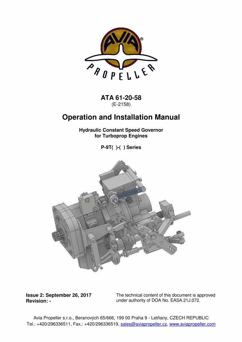
ATA 61-20-58 (E-2158)
Operation and Installation Manual
Hydraulic Constant Speed Governor for Turboprop Engines
P-9T( )-( ) Series
Issue 2: September 26, 2017 Revision: -
Avia Propeller s.r.o., Beranových 65/666, 199 00 Praha 9 - Letňany, CZECH REPUBLIC
Tel.: +420/296336511, Fax.: +420/296336519, [email protected], www.aviapropeller.com
The technical content of this document is approved under authority of DOA No. EASA.21J.072.
E-2158 Operation and Installation Manual Governor P-9T( ) Series
Warning
People who fly should recognize that various types of risks are involved; and they should take all precautions to minimize them, since they can not be eliminated entirely. The governor is a vital component of the aircraft. A mechanical failure could cause a forced landing. Governors are subject to constant vibration stresses from the engine. Before a governor is certified as being safe to operate on an airplane engine, an adequate margin of safety must be demonstrated. Even though every precaution is taken in the design and manufacture of a governor, history has revealed rare instances of failures, particularly of the fatigue type. It is essential that the governor be properly maintained according to the recommended service procedures and a close watch be exercised to detect impending problems before they become serious. Unusual operation characteristics should be investigated and repaired as it could be a warning that something serious is wrong. The governor is among the most reliable components of your airplane. It therefore deserves the care and maintenance called for in this Manual. Please give it your attention, especially the section dealing with Inspections and Checks. Thank you for choosing an Avia Propeller governor. Properly maintained it will give you many years of reliable service. Your Avia Propeller technical support team.
61-20-58 Page 2
2017-09-26
E-2158 Operation and Installation Manual Governor P-9T( ) Series
TABLE OF CONTENTS Page Table of Contents (Overview) . . . . . . . . . . . . . . . . . . . . . . . . . . . . . . . . . . . . . . . . . . . 3
List of Changes . . . . . . . . . . . . . . . . . . . . . . . . . . . . . . . . . . . . . . . . . . . . . . . . . . . . . . . . . . . 4
List of Effective Pages . . . . . . . . . . . . . . . . . . . . . . . . . . . . . . . . . . . . . . . . . . . . . . . . . . . 5
1. General . . . . . . . . . . . . . . . . . . . . . . . . . . . . . . . . . . . . . . . . . . . . . . . . . . . . . . . . . . . . . . . . 6
2. Model Designation . . . . . . . . . . . . . . . . . . . . . . . . . . . . . . . . . . . . . . . . . . . . . . . . . . . 7
3. Performance Data . . . . . . . . . . . . . . . . . . . . . . . . . . . . . . . . . . . . . . . . . . . . . . . . . . . . 8
4. Design and Operation Information . . . . . . . . . . . . . . . . . . . . . . . . . . . . . . . . . 9
5. Installation and Operation Instruction . . . . . . . . . . . . . . . . . . . . . . . . . . . . . . 13
5.1 Maximum Propeller Speed Adjustment . . . . . . . . . . . . . . . . . . . . . 19
5.2 Static Run-up . . . . . . . . . . . . . . . . . . . . . . . . . . . . . . . . . . . . . . . . . . . . . . . . . . . 20
5.3 Flight Test . . . . . . . . . . . . . . . . . . . . . . . . . . . . . . . . . . . . . . . . . . . . . . . . . . . . . . . 20
5.4 Relief Valve Pressure Adjustment . . . . . . . . . . . . . . . . . . . . . . . . . . . 20
5.5 Governor Removal . . . . . . . . . . . . . . . . . . . . . . . . . . . . . . . . . . . . . . . . . . . . . 21
6. Inspections . . . . . . . . . . . . . . . . . . . . . . . . . . . . . . . . . . . . . . . . . . . . . . . . . . . . . . . . . . . . 22
7. Trouble Shooting . . . . . . . . . . . . . . . . . . . . . . . . . . . . . . . . . . . . . . . . . . . . . . . . . . . . . 23
8. Shipping and Storage . . . . . . . . . . . . . . . . . . . . . . . . . . . . . . . . . . . . . . . . . . . . . . . . 24
Governor Installation Record . . . . . . . . . . . . . . . . . . . . . . . . . . . . . . . . . . . . . . . 25
Warranty Registration Card . . . . . . . . . . . . . . . . . . . . . . . . . . . . . . . . . . . . . . . . . 26
61-20-58 TABLE OF CONTENTS Page 3
2017-09-26

E-2158 Operation and Installation Manual Governor P-9T( ) Series
LIST OF CHANGES
Revision No. Date of Issue Pages Remark
1 - - - July 4, 2017 All Initial Issue
2 R-100/17 September 26, 2017 All Issue 2
61-20-58 LIST OF CHANGES Page 4
2017-09-26
E-2158 Operation and Installation Manual Governor P-9T( ) Series
LIST OF EFFECTIVE PAGES
Page Date of Issue
Cover 2017-09-26
2 2017-09-26
3 2017-09-26
4 2017-09-26
5 2017-09-26
6 2017-09-26
7 2017-09-26
8 2017-09-26
9 2017-09-26
10 2017-09-26
11 2017-09-26
12 2017-09-26
13 2017-09-26
14 2017-09-26
15 2017-09-26
16 2017-09-26
17 2017-09-26
18 2017-09-26
19 2017-09-26
20 2017-09-26
21 2017-09-26
22 2017-09-26
23 2017-09-26
24 2017-09-26
25 2017-09-26
26 2017-09-26
61-20-58 LIST OF EFFECTIVE PAGES Page 5
2017-09-26
E-2158 Operation and Installation Manual Governor P-9T( ) Series
1.0 GENERAL The P-9T( )-( ) hydraulic propeller governors are single acting governors developed for
hydraulically variable pitch propellers with feathering and reversing capabilities, with electric control input, optional pitch lock and synchrophasing, produced by AVIA Propeller.
1.0.1 Statement of Purpose This publication provides operation, installation and line maintenance information for the
Avia Propeller governors. Installation, removal, operation and trouble shooting data are included in this publication.
However, the airplane manufacturer's manuals and applicable propeller manuals should be used in addition to this information.
1.1 DEFINITION OF COMPONENT LIFE AND SERVICE 1.1.1 Overhaul Overhaul is a periodic process and contains the following items: - disassembly - inspection of parts - reconditioning of parts - reassembly - testing The overhaul interval is based on hours of service (operating time) or on calendar time. At such specified periods, the governors should be completely disassembled and inspected for
cracks, wear, corrosion and other unusual or abnormal conditions. As specified, certain parts should be refinished, and certain other parts should be replaced.
For overhaul interval for the governors please refer to Service Bulletin 1 at
www.aviapropeller.cz 1.1.2 Repair Repair is correction of minor damage caused during normal operation. It is done on an
irregular basis, as required. 1.1.2.1 A repair does not include an overhaul. 1.1.2.2 Amount, degree and extent of damage determines whether or not a governor can be repaired
without overhaul. 1.1.3 Component Life Component life is expressed in terms of total hours of service (TT, or Total Time) and in terms
of hours of service since overhaul (TSO, or Time Since Overhaul). Both references are necessary in defining the life of the component. Occasionally a part may
be "life limited", which means that it must be replaced after a specified period of use. Overhaul returns the component or assembly to zero hours TSO (Time Since Overhaul), but
not to zero hours TT (Total Time). No life limit is established for the governors P-9T( )-( ).
61-20-58 GENERAL Page 6
2017-09-26

E-2158 Operation and Installation Manual Governor P-9T( ) Series
2.0 MODEL DESIGNATION P - 9T 0 - 1
1 2 3 4
Legend:
1 P = Propeller governor, manufactured by AVIA Propeller 2 9T = for TP-100 turboprop engines. Pressure to decrease pitch, single acting version 3 0 = basic model, manual and electric feathering 4 1 = setting for TP-100 S/No. 16 G 003 A a b c d a = Year of Manufacture b = Governor c = Consecutive Number d = Modification
61-20-58 MODEL DESIGNATION Page 7
2017-09-26
E-2158 Operation and Installation Manual Governor P-9T( ) Series
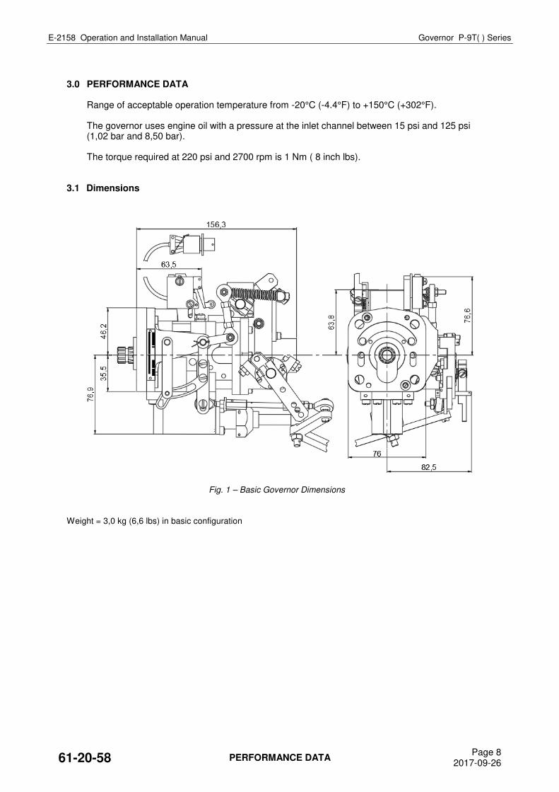
3.0 PERFORMANCE DATA Range of acceptable operation temperature from -20°C (-4.4°F) to +150°C (+302°F). The governor uses engine oil with a pressure at the inlet channel between 15 psi and 125 psi
(1,02 bar and 8,50 bar). The torque required at 220 psi and 2700 rpm is 1 Nm ( 8 inch lbs). 3.1 Dimensions
Fig. 1 – Basic Governor Dimensions
Weight = 3,0 kg (6,6 lbs) in basic configuration
61-20-58 PERFORMANCE DATA Page 8
2017-09-26
E-2158 Operation and Installation Manual Governor P-9T( ) Series
4.0 DESIGN AND OPERATION INFORMATION The Avia Propeller aircraft governor P-9T( )-( ) is base mounted centrifugal governors for use
with hydraulic constant speed propellers on single or twin turboprop engine aircraft. It regulates propeller speed by continually varying the pitch of the propeller blade to match
propeller torque (and, hence, engine load) to engine developed torque as changes occur in flight conditions. The governor is a single-acting, using oil pressure to decrease pitch. Pitch change in the opposite direction is accomplished by the force of the propeller blade counterweights twisting moment and servo spring at overspeed condition.
The principal parts of each governor are a gear-type oil pump with pressure relief valve, flyweights
pivoted on a rotating flyweight head, a spring-loaded pilot valve positioned by the flyweights, an external control lever that varies the spring load on the pilot valve, and beta valve to control blade pitch in beta mode of operation.
The body, cover and base are made of aluminum. The body contains the necessary passages to channel oil to the propeller pitch changing mechanism, and the base is designed to fit the standard AND20010 engine pad.
The sensing element of the governor is a set of pivoted flyweights mounted on a rotating flyweight
head and linked mechanically to the engine gears, through a hollow drive gear shaft. The flyweights, actuated by the centrifugal force developed by the speed of the rotation, position a
pilot valve so as to cover or uncover ports in the drive gear shaft and control the flow of oil to and from the pitch changing mechanism of the propeller. The centrifugal force exerted by the flyweights is opposed by the force of an adjustable speeder spring. The load exerted by the speeder spring determines the engine rpm required to develop sufficient centrifugal force in the flyweights to center the pilot valve. Oil to operate the propeller’s pitch changing mechanism is supplied by a gear-type oil pump at a pressure value limited by a relief valve.
WARNING – ENGINE SHUT OFF: RECOMMENDED PROPELLER POSITION DURING ENGINE SHUT OFF IS EITHER FEATHER OR
MINIMUM FLIGHT PITCH. IF THE ENGINE SHUT OFF WHEN THE PROPELLER IS IN BETA OR
REVERSE, THE ENGINE CONTROL LEVER MUST BE MOVED IN IDLE POSITION BEFORE THE
PROPELLER WILL STOP TO TURN. OTHERWISE CONTROL LINKAGE COULD BE MECHANICALLY
DAMAGED! ON SPEED: In this condition the forces action on the engine-governor-propeller combination are in a state of
balance. The speed adjusting control lever has been set by the pilot to obtain the desired engine rpm. The propeller blades are at the correct pitch to absorb the power developed by the engine. The centrifugal force of the rotating flyweights exactly balances the force of the speeder spring. The pilot valve is located in the drive-gear shaft, so that the control ports between the oil pump and the propeller pitch changing servo are covered. Pressure oil from the gear pump is circulated through open governor relief valve back to the inlet side of the pump.
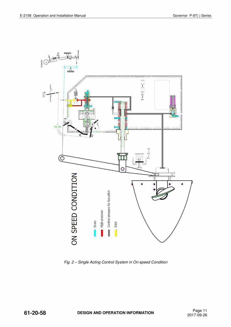
Fig. 2 and 3 show single-acting system at on-speed condition.
61-20-58 DESIGN AND OPERATION INFORMATION Page 9
2017-09-26
E-2158 Operation and Installation Manual Governor P-9T( ) Series
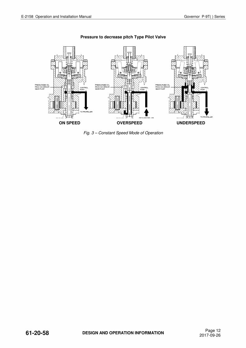
OVERSPEED: This condition occurs when airspeed or horsepower is increased and engine rpm increases above
the onspeed value - set by the speed adjusting control lever. The rotating flyweights pivot outward as their increase centrifugal force overcomes force exerted by the speeder spring.
Fig. 3 shows counterweighted propeller single-acting system. The flyweight toes raise the pilot valve plunger, uncovering ports in the driver gear shaft that
permit pressure oil to flow from the propeller pitch changing mechanism. For dual-acting control system, the valve opens also high pitch channel for pressurized oil. This allows propeller counterweights and pressurized oil in dual-acting systems to take the propeller blades toward a higher pitch. The load on the engine is increased and engine speed is reduced.
This, in turn, reduces centrifugal force exerted by the flyweights in opposition to the force of the
speeder spring. The flyweights return to an on-speed position and the pilot valve plunger covers ports in the driver gear shaft, blocking flow of pressure oil to or from the pitch changing mechanism of the propeller – return to on-speed condition.
UNDERSPEED: An underspeed condition occurs when the airspeed or horsepower is decreased and engine rpm
falls below the rate established by the setting of the speed adjusting control lever. The decrease in the centrifugal force of the rotating flyweights causes them to pivot inward under the force exerted by the speeder spring.
Fig. 3 shows counterweighted propeller single-acting system. The pilot valve plunger is forced down uncovering the ports in the drive gear shaft that allow
pressure oil to flow to the pitch changing mechanism or the propeller. This overcomes the force of the propeller counterweights and decreases the pitch of propeller blade.
This reduces the load on the engine, thereby increasing engine speed and the centrifugal force
developed by the rotating flyweights. The flyweight toes lift the pilot valve plunger to cover the control ports. At this point the forces acting on the engine-governor-propeller combination are again balanced and the engine is back to the on-speed setting.
NOTE: LOSS OF OIL FROM THE PROPELLER PITCH CHANGING MECHANISM DUE TO ENGINE TRANSFER
RING LEAKAGE WILL RESULT IN CHANGED SPEED SETTINGS. BETA RANGE, REVERSE: For ground (water) operation, the system offers reduction of blade pitch up to negative position.
After landing or during taxiing, the minimum flight pitch can be reduced by moving engine control lever below idle lock. This movement , through mechanical linkage, will open bate valve to allow propeller to go below minimum flight pitch. Position of engine control lever is proportional to blade pitch, from minimum flight pitch up to maximum reverse position.
WARNING – ENGINE SHUT OFF: RECOMMENDED PROPELLER POSITION DURING ENGINE SHUT OFF IS EITHER FEATHER OR
MINIMUM FLIGHT PITCH. IF THE ENGINE SHUT OFF WHEN THE PROPELLER IS IN BETA OR
REVERSE, THE ENGINE CONTROL LEVER MUST BE MOVED IN IDLE POSITION BEFORE THE
PROPELLER WILL STOP TO TURN. OTHERWISE CONTROL LINKAGE COULD BE MECHANICALLY
DAMAGED!
61-20-58 DESIGN AND OPERATION INFORMATION Page 10
2017-09-26
E-2158 Operation and Installation Manual Governor P-9T( ) Series
Fig. 2 – Single Acting Control System in On-speed Condition
61-20-58 DESIGN AND OPERATION INFORMATION Page 11
2017-09-26
E-2158 Operation and Installation Manual Governor P-9T( ) Series
Pressure to decrease pitch Type Pilot Valve
Fig. 3 – Constant Speed Mode of Operation
ON SPEED OVERSPEED UNDERSPEED
61-20-58 DESIGN AND OPERATION INFORMATION Page 12
2017-09-26
E-2158 Operation and Installation Manual Governor P-9T( ) Series
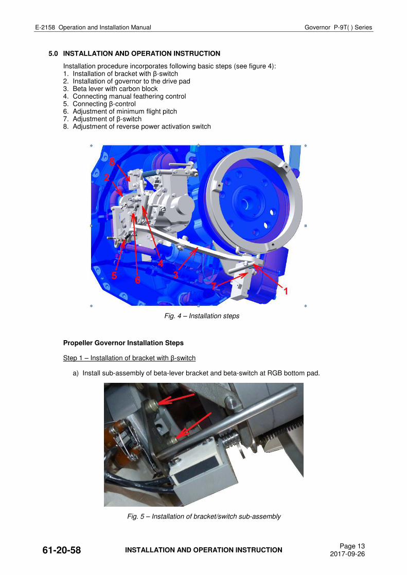
5.0 INSTALLATION AND OPERATION INSTRUCTION
Installation procedure incorporates following basic steps (see figure 4): 1. Installation of bracket with β-switch 2. Installation of governor to the drive pad 3. Beta lever with carbon block 4. Connecting manual feathering control 5. Connecting β-control 6. Adjustment of minimum flight pitch 7. Adjustment of β-switch 8. Adjustment of reverse power activation switch
Fig. 4 – Installation steps
Propeller Governor Installation Steps
Step 1 – Installation of bracket with β-switch
a) Install sub-assembly of beta-lever bracket and beta-switch at RGB bottom pad.
Fig. 5 – Installation of bracket/switch sub-assembly
61-20-58 INSTALLATION AND OPERATION INSTRUCTION Page 13
2017-09-26
E-2158 Operation and Installation Manual Governor P-9T( ) Series
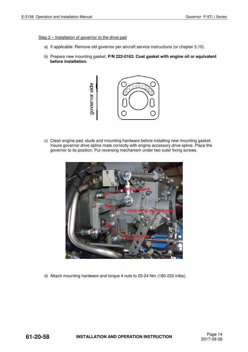
Step 2 – Installation of governor to the drive pad a) If applicable: Remove old governor per aircraft service instructions (or chapter 5.10). b) Prepare new mounting gasket, P/N 222-0163. Coat gasket with engine oil or equivalent
before installation.
c) Clean engine pad, studs and mounting hardware before installing new mounting gasket. Insure governor drive spline mate correctly with engine accessory drive spline. Place the governor to its position. Put reversing mechanism under two outer fixing screws.
d) Attach mounting hardware and torque 4 nuts to 20-24 Nm (180-220 inIbs).
61-20-58 INSTALLATION AND OPERATION INSTRUCTION Page 14
2017-09-26
E-2158 Operation and Installation Manual Governor P-9T( ) Series
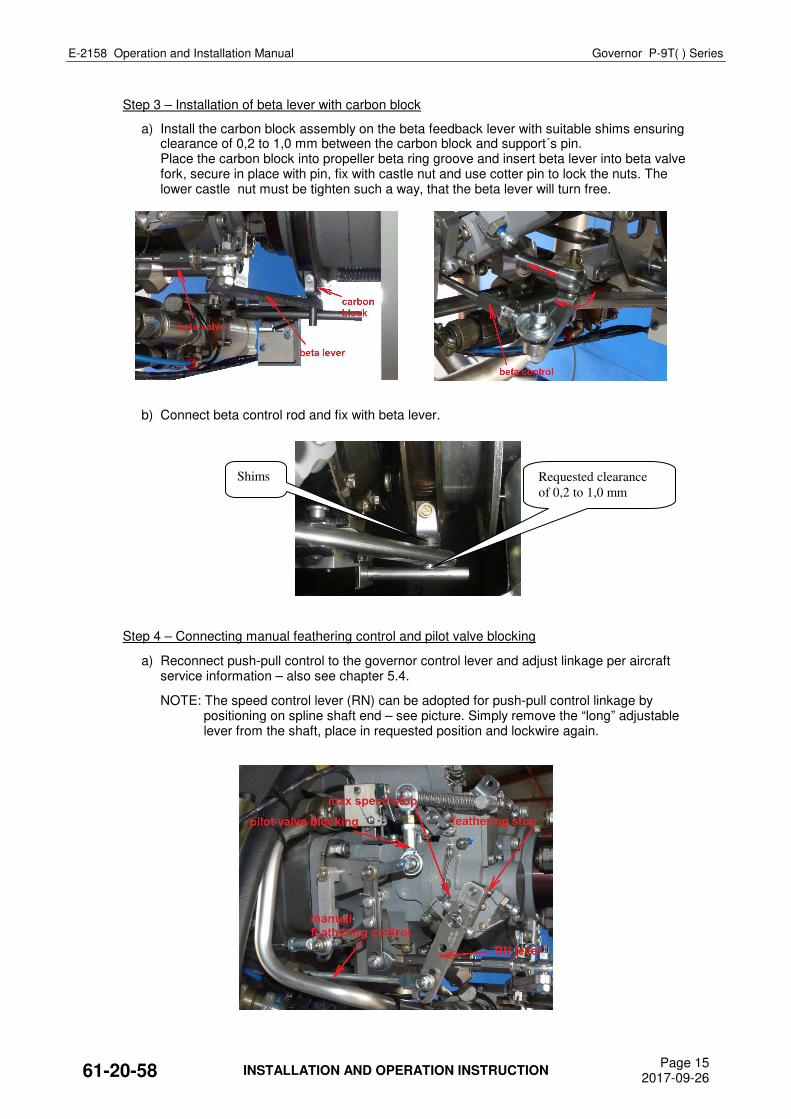
Step 3 – Installation of beta lever with carbon block
a) Install the carbon block assembly on the beta feedback lever with suitable shims ensuring clearance of 0,2 to 1,0 mm between the carbon block and support´s pin.
Place the carbon block into propeller beta ring groove and insert beta lever into beta valve fork, secure in place with pin, fix with castle nut and use cotter pin to lock the nuts. The lower castle nut must be tighten such a way, that the beta lever will turn free.
b) Connect beta control rod and fix with beta lever.
Step 4 – Connecting manual feathering control and pilot valve blocking
a) Reconnect push-pull control to the governor control lever and adjust linkage per aircraft service information – also see chapter 5.4.
NOTE: The speed control lever (RN) can be adopted for push-pull control linkage by positioning on spline shaft end – see picture. Simply remove the “long” adjustable lever from the shaft, place in requested position and lockwire again.
61-20-58 INSTALLATION AND OPERATION INSTRUCTION Page 15
2017-09-26
Requested clearance
of 0,2 to 1,0 mm
Shims
E-2158 Operation and Installation Manual Governor P-9T( ) Series
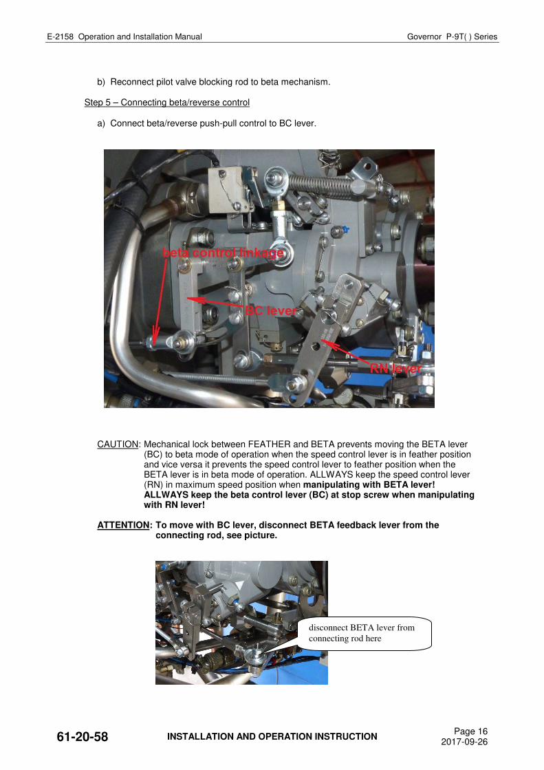
b) Reconnect pilot valve blocking rod to beta mechanism. Step 5 – Connecting beta/reverse control a) Connect beta/reverse push-pull control to BC lever.
CAUTION: Mechanical lock between FEATHER and BETA prevents moving the BETA lever (BC) to beta mode of operation when the speed control lever is in feather position and vice versa it prevents the speed control lever to feather position when the BETA lever is in beta mode of operation. ALLWAYS keep the speed control lever (RN) in maximum speed position when manipulating with BETA lever! ALLWAYS keep the beta control lever (BC) at stop screw when manipulating with RN lever!
ATTENTION: To move with BC lever, disconnect BETA feedback lever from the
connecting rod, see picture.
61-20-58 INSTALLATION AND OPERATION INSTRUCTION Page 16
2017-09-26
disconnect BETA lever from
connecting rod here
E-2158 Operation and Installation Manual Governor P-9T( ) Series
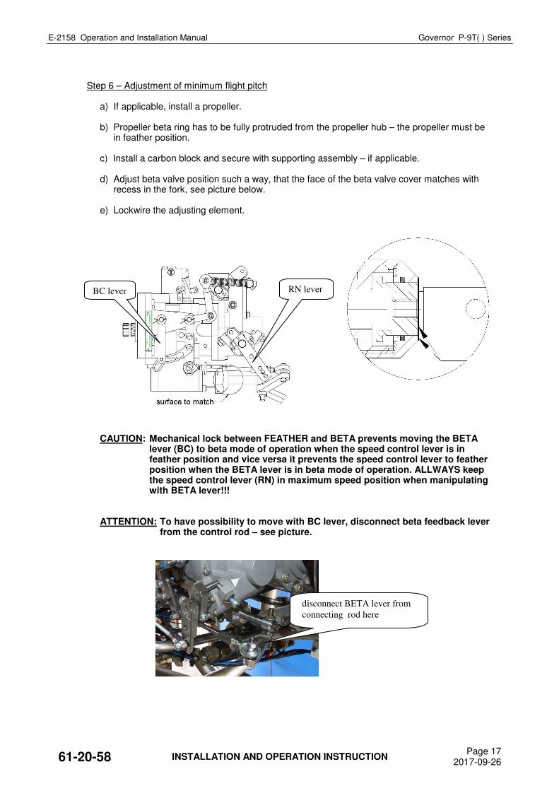
Step 6 – Adjustment of minimum flight pitch a) If applicable, install a propeller. b) Propeller beta ring has to be fully protruded from the propeller hub – the propeller must be
in feather position. c) Install a carbon block and secure with supporting assembly – if applicable. d) Adjust beta valve position such a way, that the face of the beta valve cover matches with
recess in the fork, see picture below. e) Lockwire the adjusting element.
CAUTION: Mechanical lock between FEATHER and BETA prevents moving the BETA lever (BC) to beta mode of operation when the speed control lever is in feather position and vice versa it prevents the speed control lever to feather position when the BETA lever is in beta mode of operation. ALLWAYS keep the speed control lever (RN) in maximum speed position when manipulating with BETA lever!!!
ATTENTION: To have possibility to move with BC lever, disconnect beta feedback lever
from the control rod – see picture.
61-20-58 INSTALLATION AND OPERATION INSTRUCTION Page 17
2017-09-26
BC lever RN lever
disconnect BETA lever from
connecting rod here
E-2158 Operation and Installation Manual Governor P-9T( ) Series
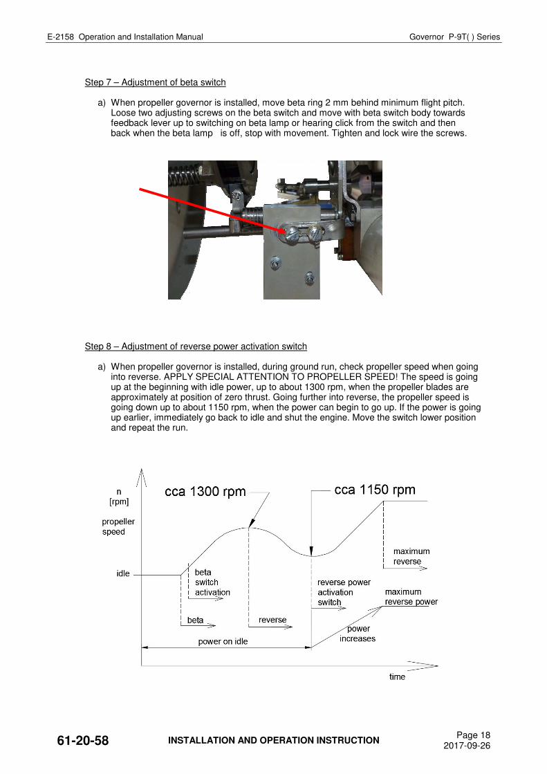
Step 7 – Adjustment of beta switch a) When propeller governor is installed, move beta ring 2 mm behind minimum flight pitch.
Loose two adjusting screws on the beta switch and move with beta switch body towards feedback lever up to switching on beta lamp or hearing click from the switch and then back when the beta lamp is off, stop with movement. Tighten and lock wire the screws.
Step 8 – Adjustment of reverse power activation switch a) When propeller governor is installed, during ground run, check propeller speed when going
into reverse. APPLY SPECIAL ATTENTION TO PROPELLER SPEED! The speed is going up at the beginning with idle power, up to about 1300 rpm, when the propeller blades are approximately at position of zero thrust. Going further into reverse, the propeller speed is going down up to about 1150 rpm, when the power can begin to go up. If the power is going up earlier, immediately go back to idle and shut the engine. Move the switch lower position and repeat the run.
61-20-58 INSTALLATION AND OPERATION INSTRUCTION Page 18
2017-09-26
E-2158 Operation and Installation Manual Governor P-9T( ) Series
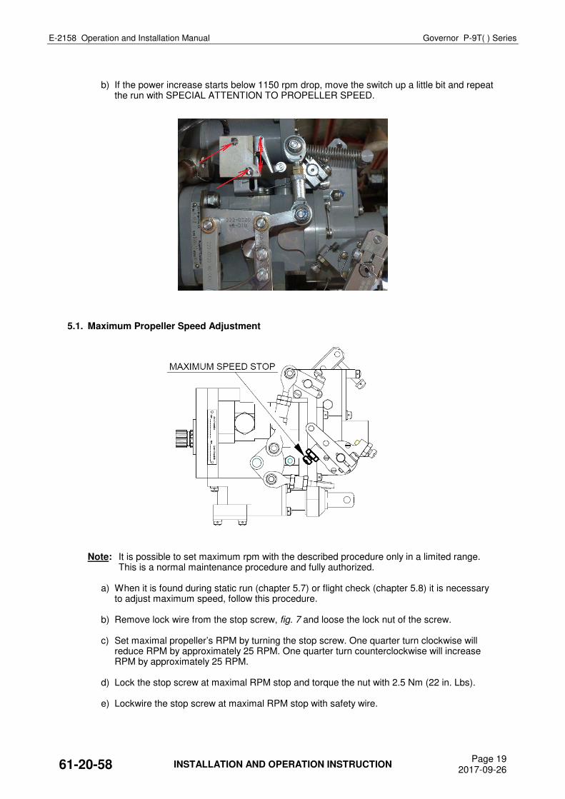
b) If the power increase starts below 1150 rpm drop, move the switch up a little bit and repeat
the run with SPECIAL ATTENTION TO PROPELLER SPEED.
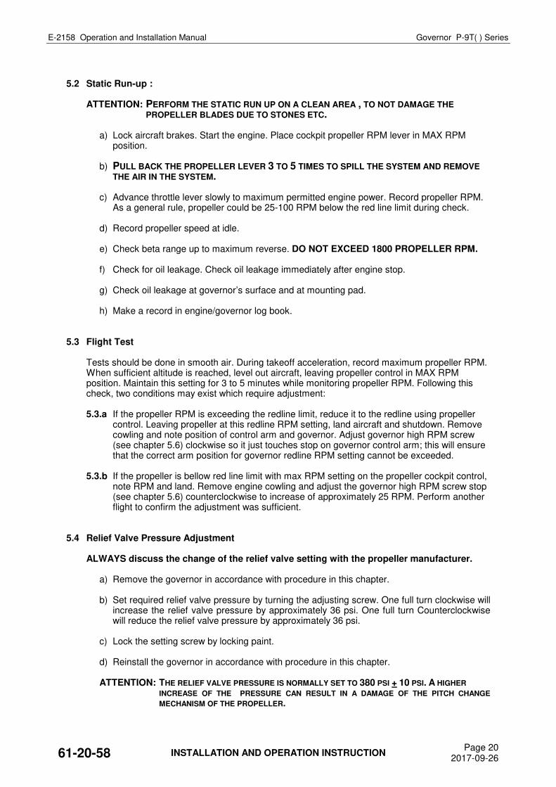
5.1. Maximum Propeller Speed Adjustment
Note: It is possible to set maximum rpm with the described procedure only in a limited range. This is a normal maintenance procedure and fully authorized.
a) When it is found during static run (chapter 5.7) or flight check (chapter 5.8) it is necessary
to adjust maximum speed, follow this procedure. b) Remove lock wire from the stop screw, fig. 7 and loose the lock nut of the screw. c) Set maximal propeller’s RPM by turning the stop screw. One quarter turn clockwise will
reduce RPM by approximately 25 RPM. One quarter turn counterclockwise will increase RPM by approximately 25 RPM.
d) Lock the stop screw at maximal RPM stop and torque the nut with 2.5 Nm (22 in. Lbs). e) Lockwire the stop screw at maximal RPM stop with safety wire.
61-20-58 INSTALLATION AND OPERATION INSTRUCTION Page 19
2017-09-26
E-2158 Operation and Installation Manual Governor P-9T( ) Series
5.2 Static Run-up : ATTENTION: PERFORM THE STATIC RUN UP ON A CLEAN AREA , TO NOT DAMAGE THE
PROPELLER BLADES DUE TO STONES ETC. a) Lock aircraft brakes. Start the engine. Place cockpit propeller RPM lever in MAX RPM
position. b) PULL BACK THE PROPELLER LEVER 3 TO 5 TIMES TO SPILL THE SYSTEM AND REMOVE
THE AIR IN THE SYSTEM. c) Advance throttle lever slowly to maximum permitted engine power. Record propeller RPM.
As a general rule, propeller could be 25-100 RPM below the red line limit during check. d) Record propeller speed at idle. e) Check beta range up to maximum reverse. DO NOT EXCEED 1800 PROPELLER RPM. f) Check for oil leakage. Check oil leakage immediately after engine stop. g) Check oil leakage at governor’s surface and at mounting pad. h) Make a record in engine/governor log book. 5.3 Flight Test Tests should be done in smooth air. During takeoff acceleration, record maximum propeller RPM.
When sufficient altitude is reached, level out aircraft, leaving propeller control in MAX RPM position. Maintain this setting for 3 to 5 minutes while monitoring propeller RPM. Following this check, two conditions may exist which require adjustment:
5.3.a If the propeller RPM is exceeding the redline limit, reduce it to the redline using propeller
control. Leaving propeller at this redline RPM setting, land aircraft and shutdown. Remove cowling and note position of control arm and governor. Adjust governor high RPM screw (see chapter 5.6) clockwise so it just touches stop on governor control arm; this will ensure that the correct arm position for governor redline RPM setting cannot be exceeded.
5.3.b If the propeller is bellow red line limit with max RPM setting on the propeller cockpit control,
note RPM and land. Remove engine cowling and adjust the governor high RPM screw stop (see chapter 5.6) counterclockwise to increase of approximately 25 RPM. Perform another flight to confirm the adjustment was sufficient.
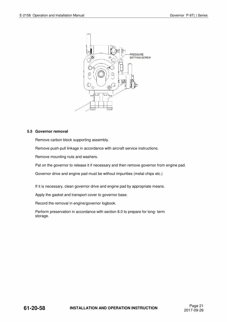
5.4 Relief Valve Pressure Adjustment
ALWAYS discuss the change of the relief valve setting with the propeller manufacturer. a) Remove the governor in accordance with procedure in this chapter. b) Set required relief valve pressure by turning the adjusting screw. One full turn clockwise will
increase the relief valve pressure by approximately 36 psi. One full turn Counterclockwise will reduce the relief valve pressure by approximately 36 psi.
c) Lock the setting screw by locking paint. d) Reinstall the governor in accordance with procedure in this chapter. ATTENTION: THE RELIEF VALVE PRESSURE IS NORMALLY SET TO 380 PSI + 10 PSI. A HIGHER INCREASE OF THE PRESSURE CAN RESULT IN A DAMAGE OF THE PITCH CHANGE
MECHANISM OF THE PROPELLER.
61-20-58 INSTALLATION AND OPERATION INSTRUCTION Page 20
2017-09-26
E-2158 Operation and Installation Manual Governor P-9T( ) Series
5.5 Governor removal Remove carbon block supporting assembly. Remove push-pull linkage in accordance with aircraft service instructions. Remove mounting nuts and washers. Pat on the governor to release it if necessary and then remove governor from engine pad. Governor drive and engine pad must be without impurities (metal chips etc.) If it is necessary, clean governor drive and engine pad by appropriate means. Apply the gasket and transport cover to governor base. Record the removal in engine/governor logbook. Perform preservation in accordance with section 8.0 to prepare for long- term storage.
61-20-58 INSTALLATION AND OPERATION INSTRUCTION Page 21
2017-09-26
E-2158 Operation and Installation Manual Governor P-9T( ) Series
6.0 INSPECTIONS Check for oil leakage. Check oil leakage immediately after engine stop. Check oil leakage at governor’s surface and at mounting pad. If oil leakage is detected, check stop nuts at the governor housing and the mounting nuts.
Torque if necessary. If oil leakage is detected repeatedly contact service center or governor’s manufacturer.
WARNING: NO OIL LEAKAGE IS PERMITTED.
61-20-58 INSPECTIONS Page 22
2017-09-26
E-2158 Operation and Installation Manual Governor P-9T( ) Series
7.0 TROUBLE SHOOTING Propeller Surging or "Wandering" - Possible Causes: 7.1 EXCESSIVE TRANSFER BEARING LEAKAGE Engines with excessive transfer bearing leakage can experience surging since the governor may
not be able to get enough pressure to the propeller. This causes a delay in propeller responsiveness and by the time the propeller responds to earlier governor inputs, they have changed, resulting in propeller "wandering".
Solution: Perform a transfer bearing leakage test per engine manufacturer's instructions. If test
indicates a high rate of leakage (even though it may still be on the high side of "acceptable" tolerance), this maybe your cause. Install the suspect governor on a known "good" aircraft, if problem disappears, engine work may be indicated.
7.2 MALFUNCTIONING fuel control unit 7.3 DIRTY ENGINE OIL Contaminants in dirty engine oil can cause blockage of close tolerance passages in governor,
leading to erratic operation. Solution: Timely engine oil changes should eliminate this problem. 7.4 EXCESSIVE "PLAY" IN AIRCRAFT PROPELLER CONTROL LINKAGE Excessive "play" in the linkage between the governor and the cockpit control often leads to erratic
operation. Specifically, if the propeller RPM is suddenly changing and holding a new setting on its own, this could indicate loose linkage.
Solution: Trace linkage and locate unsecured sections and tighten-up as needed. Please note
that although linkage may appear to allow full governor control while the engine is off, it may not in the air. Engine vibration and "stretch" of the mount during operation can often aggravate the condition. Therefore, it is important the entire length of linkage be properly secured, even if the ends alone are tight.
7.5 EXCESSIVE PROPELLER FRICTION (NOTE: This is rarely the cause of RPM malfunction.) Propeller may be overly-resistant to pitch movement. This can be caused by either excessively
tight shimming of the propeller blades, or internal corrosion or part failure, causing binding. Solution: Check amount of blade ”play" as defined below: A total lack of blade "shake" may indicate excessively tight blade shims. If this is suspected, have
the propeller checked by a qualified EASA/FAA-approved propeller repairman. Note that this check and any needed correction can usually be performed with the propeller installed on the aircraft.
61-20-58 TROUBLE SHOOTING Page 23
2017-09-26
E-2158 Operation and Installation Manual Governor P-9T( ) Series
8.0 SHIPPING AND STORAGE Conservation Inner conservation is automatically done by engine oil. Attach cover cap. After installing the governor the conservation is done together with engine in accordance with the
instruction of the engine manufacturer. Outside conservation isn’t required. Pack the governor in two layers of wax-cloth and put it in a plastic bag. The plastic bag should be
vacuumed and after that welded. Make a note in the governor’s logbook. Deconservation isn’t needed. Storage Governors have to be packed in carton box with accessory documentation. Store governors in temperature from +10°C (+50°F) to +30°C (+86 °F) and relative humidity from
40 % to 80 %. Keep stock room free of gases with deleterious effect.
61-20-58 SHIPPING AND STORAGE Page 24
2017-09-26
E-2158 Operation and Installation Manual Governor P-9T( ) Series
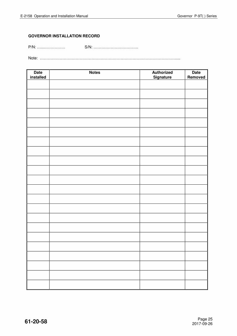
GOVERNOR INSTALLATION RECORD
P/N: …....…………… S/N: …………………………….
Note: ………………………………………………………………………………………….....
Date installed
Notes Authorized Signature
Date Removed
61-20-58 Page 25
2017-09-26
E-2158 Operation and Installation Manual Governor P-9T( ) Series
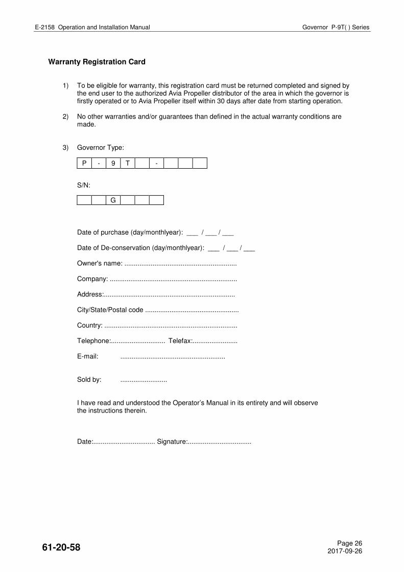
Warranty Registration Card 1) To be eligible for warranty, this registration card must be returned completed and signed by
the end user to the authorized Avia Propeller distributor of the area in which the governor is firstly operated or to Avia Propeller itself within 30 days after date from starting operation.
2) No other warranties and/or guarantees than defined in the actual warranty conditions are made.
3) Governor Type:
P - 9 T -
S/N:
G
Date of purchase (day/monthlyear): ___ / ___ / ___ Date of De-conservation (day/monthlyear): ___ / ___ / ___ Owner's name: ............................................................ Company: .................................................................... Address:...................................................................... City/State/Postal code .................................................. Country: ....................................................................... Telephone:............................. Telefax:........................ E-mail: ........................................................ Sold by: ......................... I have read and understood the Operator’s Manual in its entirety and will observe
the instructions therein. Date:................................. Signature:..................................
61-20-58 Page 26
2017-09-26