operating systems b.tech cse iii year i … lecture... · lecture notes on operating systems b.tech...
TRANSCRIPT
CREC, Dept. of CSE
LECTURE NOTES
ON
OPERATING SYSTEMS
B.TECH CSE III YEAR I SEMESTER(JNTUA-R13)
Mrs. N.HEMALATHAASST.PROFESSOR
DEPARTMENT OF COMPUTER SCIENCE & ENGINEERING
CHADALAWADA RAMANAMMA ENGINEERING COLLEGECHADALAWADA NAGAR, RENIGUNTA ROAD, TIRUPATI (A.P) - 517506
JAWAHARLAL NEHRU TECHNOLOGICAL UNIVERSITY ANANTAPUR
B.Tech. III - I Sem. Th Tu C3 1 3
(13A05501) OPERATING SYSTEMS
Course Objective:
• To make the students understand the basic operating system concepts such as processes, threads, scheduling, synchronization, deadlocks, memory management, file and I/O subsystems and protection.• To get acquaintance with the class of abstractions afford by general purpose operating systems that aid the development of user applications.
Learning Outcome:
• Able to use operating systems effectively.• Write System and application programs to exploit operating system functionality.• Add functionality to the exiting operating systems • Design new operating systems.
UNIT IOperating Systems Overview: Operating system functions, Operating system structure, operatingsystems Operations, protection and security, Kernel data Structures, Computing Environments, Open-Source Operating SystemsOperating System Structure: Operating System Services, User and Operating-System Interface,systems calls, Types of System Calls, system programs, operating system structure, operating systemdebugging, System Boot.Processes: Process concept, process Scheduling, Operations on processes, Inter processCommunication, Examples of IPC systems.
UNIT IIThreads: overview, Multicore Programming, Multithreading Models, Thread Libraries, Implicitthreading, Threading Issues.Process Synchronization: The critical-section problem, Peterson‘s Solution, SynchronizationHardware, Mutex Locks, Semaphores, Classic problems of synchronization, Monitors,Synchronization examples, Alternative approaches.CPU Scheduling: Scheduling-Criteria, Scheduling Algorithms, Thread Scheduling, Multiple-Processor Scheduling, Real-Time CPU Scheduling, Algorithm Evaluation.
UNIT IIIMemory Management: Swapping, contiguous memory allocation, segmentation, paging, structure ofthe page table.Virtual memory: demand paging, page-replacement, Allocation of frames, Thrashing, Memory-Mapped Files, Allocating Kernel MemoryDeadlocks: System Model, deadlock characterization, Methods of handling Deadlocks, Deadlockprevention, Detection and Avoidance, Recovery from deadlock.
UNIT IVMass-storage structure: Overview of Mass-storage structure, Disk structure, Disk attachment, Diskscheduling, Swap-space management, RAID structure, Stable-storage implementation.File system Interface: The concept of a file, Access Methods, Directory and Disk structure, Filesystem mounting, File sharing, Protection.File system Implementation: File-system structure, File-system Implementation, DirectoryImplementation, Allocation Methods, Free-Space management.
UNIT VI/O systems: I/O Hardware, Application I/O interface, Kernel I/O subsystem, Transforming I/Orequests to Hardware operations.Protection: Goals of Protection, Principles of Protection, Domain of protection, Access Matrix,Implementation of Access Matrix, Access control, Revocation of Access Rights, Capability- Basedsystems, Language – Based ProtectionSecurity: The Security problem, Program threats, System and Network threats, Cryptography as asecurity tool, User authentication, Implementing security defenses, Firewalling to protect systems andnetworks, Computer–security classifications.
Text Books:1. Operating System Concepts, Abraham Silberchatz, Peter B. Galvin, Greg Gagne, Ninth Edition,2012, Wiley.2. Operating Systems: Internals and Design Principles, Stallings, Sixth Edition, 2009, PearsonEducation.Reference Books:1. Modern Operating Systems, Andrew S Tanenbaum, Second Edition, PHI.2. Operating Systems, S.Haldar, A.A.Aravind, Pearson Education.3. Principles of Operating Systems, B.L.Stuart, Cengage learning, India Edition.4. Operating Systems, A.S.Godbole, Second Edition, TMH.5. An Introduction to Operating Systems, P.C.P. Bhatt, PHI.6. Operating Systems, G.Nutt, N.Chaki and S.Neogy, Third Edition, Pearson Education.7. Operating Systems, R.Elmasri, A,G.Carrick and D.Levine, Mc Graw Hill.
CREC, Dept. of CSE Page 1
UNIT-1
Operating System Overview
Operating System Definition:
OS is a resource allocator
∑ Manages all resources∑ Decides between conflicting requests for efficient and fair resource use
OS is a control program
∑ Controls execution of programs to prevent errors and improper use of the computer
Operating System Structure:
Multiprogramming needed for efficiency
∑ Single user cannot keep CPU and I/O devices busy at all times
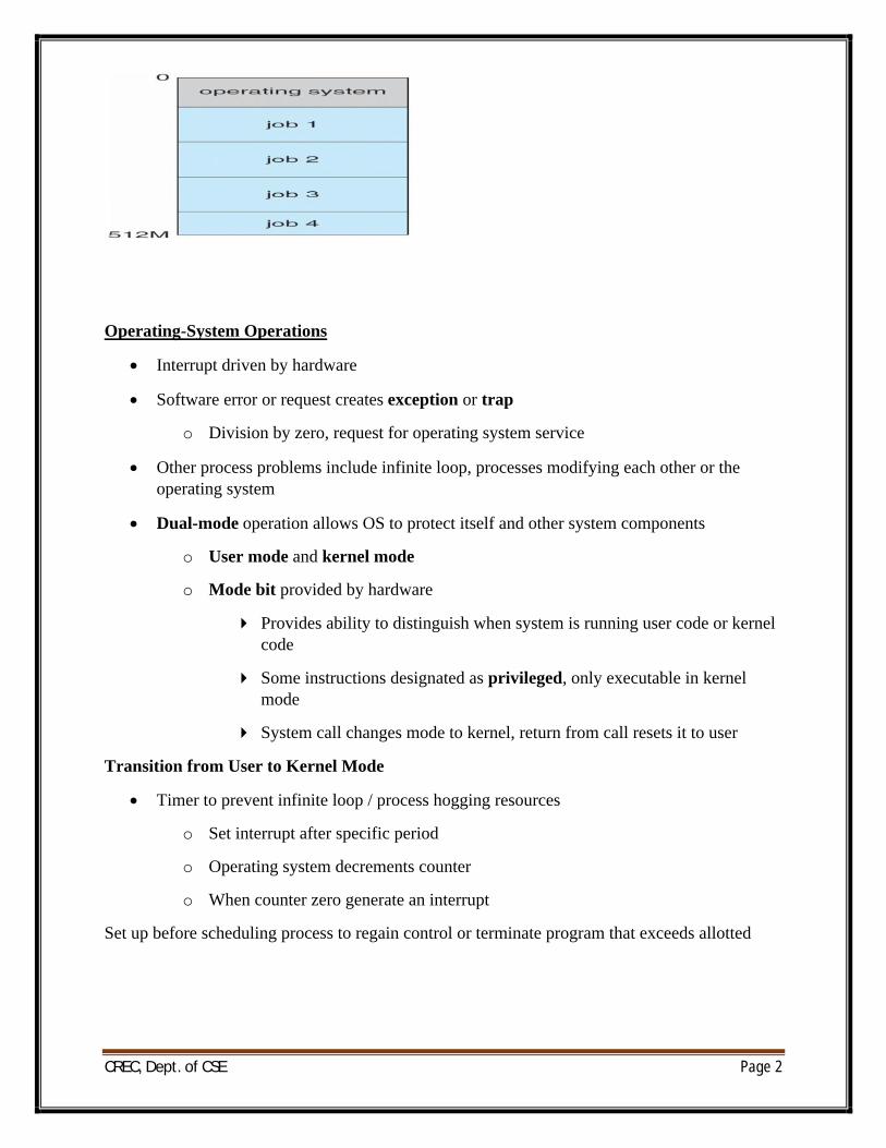
∑ Multiprogramming organizes jobs (code and data) so CPU always has one to execute
∑ A subset of total jobs in system is kept in memory
∑ One job selected and run via job scheduling
∑ When it has to wait (for I/O for example), OS switches to another job
Timesharing (multitasking) is logical extension in which CPU switches jobs so frequently that users can interact with each job while it is running, creating interactive computing
∑ Response time should be < 1 second
∑ Each user has at least one program executing in memory [process
∑ If several jobs ready to run at the same time [CPU scheduling
∑ If processes don’t fit in memory, swapping moves them in and out to run
∑ Virtual memory allows execution of processes not completely in memory
Memory Layout for Multi programmed System
CREC, Dept. of CSE Page 2
Operating-System Operations
∑ Interrupt driven by hardware
∑ Software error or request creates exception or trap
o Division by zero, request for operating system service
∑ Other process problems include infinite loop, processes modifying each other or the operating system
∑ Dual-mode operation allows OS to protect itself and other system components
o User mode and kernel mode
o Mode bit provided by hardware
4 Provides ability to distinguish when system is running user code or kernel code
4 Some instructions designated as privileged, only executable in kernel mode
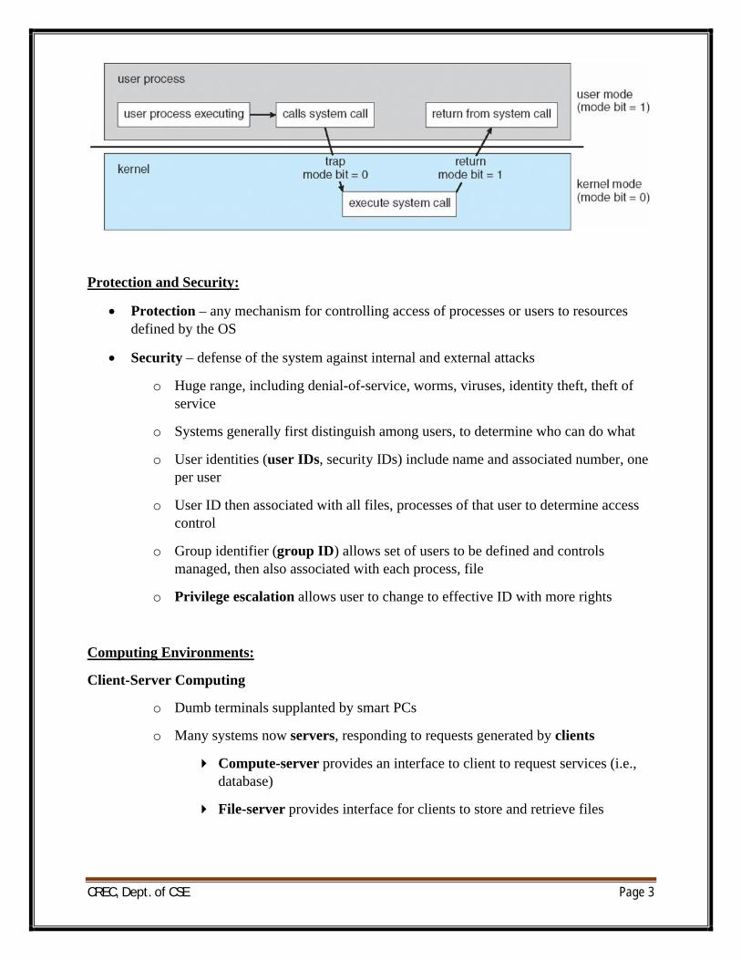
4 System call changes mode to kernel, return from call resets it to user
Transition from User to Kernel Mode
∑ Timer to prevent infinite loop / process hogging resources
o Set interrupt after specific period
o Operating system decrements counter
o When counter zero generate an interrupt
Set up before scheduling process to regain control or terminate program that exceeds allotted
CREC, Dept. of CSE Page 3
Protection and Security:
∑ Protection – any mechanism for controlling access of processes or users to resources defined by the OS
∑ Security – defense of the system against internal and external attacks
o Huge range, including denial-of-service, worms, viruses, identity theft, theft of service
o Systems generally first distinguish among users, to determine who can do what
o User identities (user IDs, security IDs) include name and associated number, one per user
o User ID then associated with all files, processes of that user to determine access control
o Group identifier (group ID) allows set of users to be defined and controls managed, then also associated with each process, file
o Privilege escalation allows user to change to effective ID with more rights
Computing Environments:
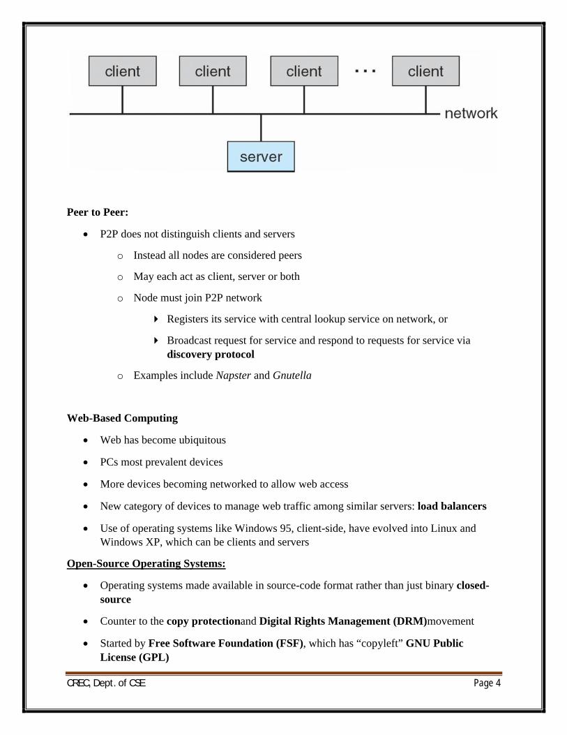
Client-Server Computing
o Dumb terminals supplanted by smart PCs
o Many systems now servers, responding to requests generated by clients
4 Compute-server provides an interface to client to request services (i.e., database)
4 File-server provides interface for clients to store and retrieve files
CREC, Dept. of CSE Page 4
Peer to Peer:
∑ P2P does not distinguish clients and servers
o Instead all nodes are considered peers
o May each act as client, server or both
o Node must join P2P network
4 Registers its service with central lookup service on network, or
4 Broadcast request for service and respond to requests for service via discovery protocol
o Examples include Napster and Gnutella
Web-Based Computing
∑ Web has become ubiquitous
∑ PCs most prevalent devices
∑ More devices becoming networked to allow web access
∑ New category of devices to manage web traffic among similar servers: load balancers
∑ Use of operating systems like Windows 95, client-side, have evolved into Linux and Windows XP, which can be clients and servers
Open-Source Operating Systems:
∑ Operating systems made available in source-code format rather than just binary closed-source
∑ Counter to the copy protectionand Digital Rights Management (DRM)movement
∑ Started by Free Software Foundation (FSF), which has “copyleft” GNU Public License (GPL)
CREC, Dept. of CSE Page 5
∑ Examples include GNU/Linux and BSD UNIX(including core of Mac OS X), and many more
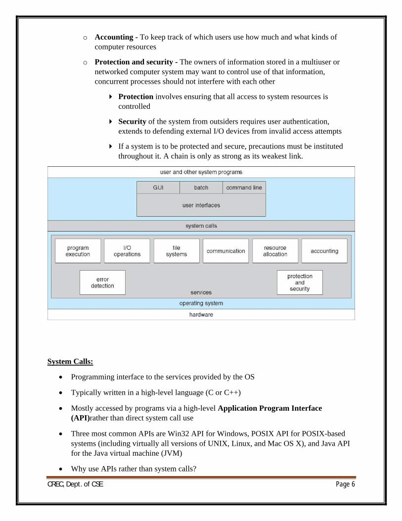
Operating System Services:
∑ Operating systems provide an environment for execution of programs and services to programs and users
∑ One set of operating-system services provides functions that are helpful to the user:
o User interface - Almost all operating systems have a user interface (UI).
4 Varies between Command-Line (CLI), Graphics User Interface (GUI),Batch
o Program execution - The system must be able to load a program into memory and to run that program, end execution, either normally or abnormally (indicating error)
o I/O operations - A running program may require I/O, which may involve a file or an I/O device
o File-system manipulation - The file system is of particular interest. Programs need to read and write files and directories, create and delete them, search them, list file Information, permission management.
o Communications – Processes may exchange information, on the same computer or between computers over a network
4 Communications may be via shared memory or through message passing (packets moved by the OS)
o Error detection – OS needs to be constantly aware of possible errors
4 May occur in the CPU and memory hardware, in I/O devices, in user program
4 For each type of error, OS should take the appropriate action to ensure correct and consistent computing
4 Debugging facilities can greatly enhance the user’s and programmer’s abilities to efficiently use the system
∑ Another set of OS functions exists for ensuring the efficient operation of the system itself via resource sharing
o Resource allocation - When multiple users or multiple jobs running concurrently, resources must be allocated to each of them
4 Many types of resources - Some (such as CPU cycles, main memory, and file storage) may have special allocation code, others (such as I/O devices) may have general request and release code
CREC, Dept. of CSE Page 6
o Accounting - To keep track of which users use how much and what kinds of computer resources
o Protection and security - The owners of information stored in a multiuser or networked computer system may want to control use of that information, concurrent processes should not interfere with each other
4 Protection involves ensuring that all access to system resources is controlled
4 Security of the system from outsiders requires user authentication, extends to defending external I/O devices from invalid access attempts
4 If a system is to be protected and secure, precautions must be instituted throughout it. A chain is only as strong as its weakest link.
System Calls:
∑ Programming interface to the services provided by the OS
∑ Typically written in a high-level language (C or C++)
∑ Mostly accessed by programs via a high-level Application Program Interface (API)rather than direct system call use
∑ Three most common APIs are Win32 API for Windows, POSIX API for POSIX-based systems (including virtually all versions of UNIX, Linux, and Mac OS X), and Java API for the Java virtual machine (JVM)
∑ Why use APIs rather than system calls?
CREC, Dept. of CSE Page 7
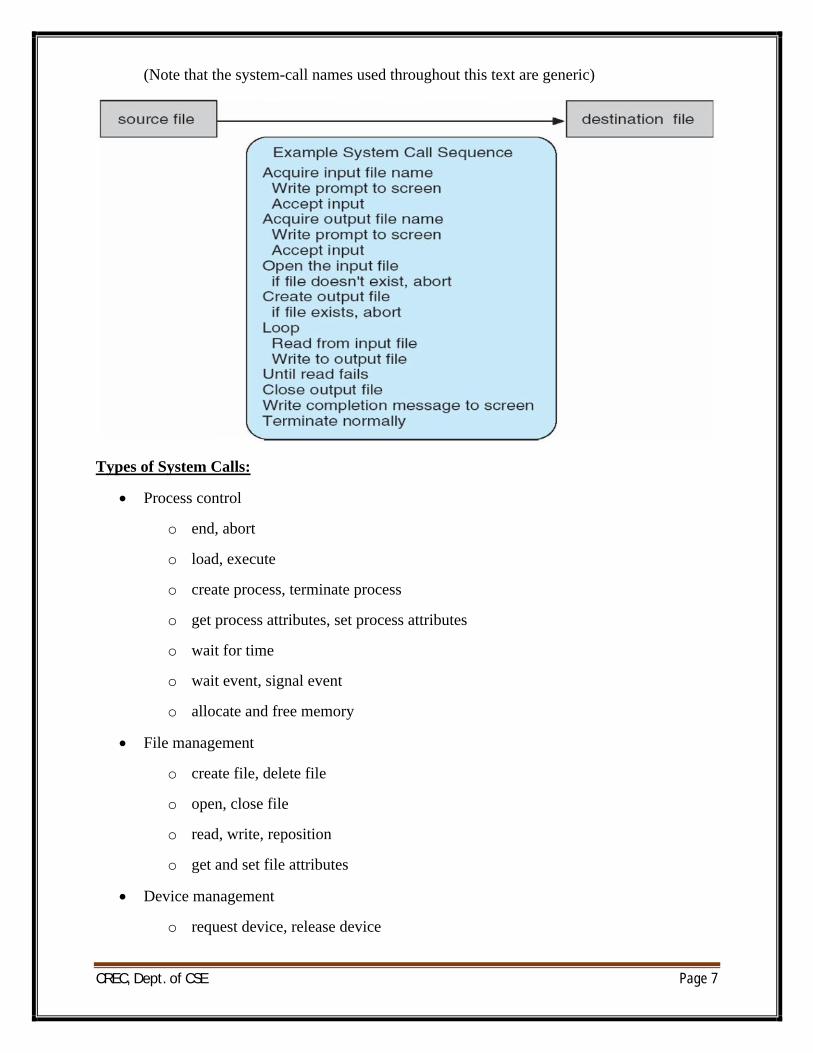
(Note that the system-call names used throughout this text are generic)
Types of System Calls:
∑ Process control
o end, abort
o load, execute
o create process, terminate process
o get process attributes, set process attributes
o wait for time
o wait event, signal event
o allocate and free memory
∑ File management
o create file, delete file
o open, close file
o read, write, reposition
o get and set file attributes
∑ Device management
o request device, release device
CREC, Dept. of CSE Page 8
o read, write, reposition
o get device attributes, set device attributes
o logically attach or detach devices
∑ Information maintenance
o get time or date, set time or date
o get system data, set system data
o get and set process, file, or device attributes
∑ Communications
o create, delete communication connection
o send, receive messages
o transfer status information
o attach and detach remote devices
System Programs:
∑ System programs provide a convenient environment for program development and execution. They can be divided into:
o File manipulation
o Status information
o File modification
o Programming language support
o Program loading and execution
o Communications
o Application programs
o Most users’ view of the operation system is defined by system programs, not the actual system calls
∑ Provide a convenient environment for program development and execution
o Some of them are simply user interfaces to system calls; others are considerably more complex
o File management - Create, delete, copy, rename, print, dump, list, and generally manipulate files and directories
∑ Status information
CREC, Dept. of CSE Page 9
o Some ask the system for info - date, time, amount of available memory, disk space, number of users
o Others provide detailed performance, logging, and debugging information
o Typically, these programs format and print the output to the terminal or other output devices
o Some systems implement a registry - used to store and retrieve configuration information
∑ File modification
o Text editors to create and modify files
o Special commands to search contents of files or perform transformations of the text
o Programming-language support - Compilers, assemblers, debuggers and interpreters sometimes provided
∑ Program loading and execution- Absolute loaders, relocatable loaders, linkage editors, and overlay-loaders, debugging systems for higher-level and machine language
∑ Communications - Provide the mechanism for creating virtual connections among processes, users, and computer systems
o Allow users to send messages to one another’s screens, browse web pages, send electronic-mail messages, log in remotely, transfer files from one machine to another
Operating-System Debugging:
∑ Debuggingis finding and fixing errors, or bugs
∑ OSes generate log filescontaining error information
∑ Failure of an application can generate core dumpfile capturing memory of the process
∑ Operating system failure can generate crash dumpfile containing kernel memory
∑ Beyond crashes, performance tuning can optimize system performance
∑ Kernighan’s Law: “Debugging is twice as hard as writing the code in the first place. Therefore, if you write the code as cleverly as possible, you are, by definition, not smart enough to debug it.”
∑ DTrace tool in Solaris, FreeBSD, Mac OS X allows live instrumentation on production systems
o Probes fire when code is executed, capturing state data and sending it to consumers of those probes
Operating System Generation:
CREC, Dept. of CSE Page 10
∑ Operating systems are designed to run on any of a class of machines; the system must be configured for each specific computer site
∑ SYSGEN program obtains information concerning the specific configuration of the hardware system
∑ Booting – starting a computer by loading the kernel
∑ Bootstrap program – code stored in ROM that is able to locate the kernel, load it into memory, and start its execution
System Boot
∑ Operating system must be made available to hardware so hardware can start it
o Small piece of code – bootstrap loader, locates the kernel, loads it into memory, and starts it
o Sometimes two-step process where boot block at fixed location loads bootstrap loader
o When power initialized on system, execution starts at a fixed memory location
4 Firmware used to hold initial boot code
Process Concept:
∑ An operating system executes a variety of programs:
o Batch system – jobs
o Time-shared systems – user programs or tasks
o Textbook uses the terms job and process almost interchangeably
∑ Process – a program in execution; process execution must progress in sequential fashion
∑ A process includes:
o program counter
o stack
o data section
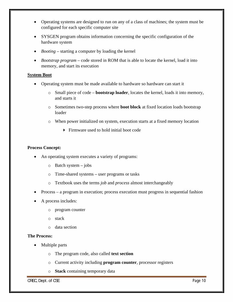
The Process:
∑ Multiple parts
o The program code, also called text section
o Current activity including program counter, processor registers
o Stack containing temporary data
CREC, Dept. of CSE Page 11
4 Function parameters, return addresses, local variables
o Data section containing global variables
o Heap containing memory dynamically allocated during run time
∑ Program is passive entity, process is active
o Program becomes process when executable file loaded into memory
∑ Execution of program started via GUI mouse clicks, command line entry of its name, etc
∑ One program can be several processes
o Consider multiple users executing the same program
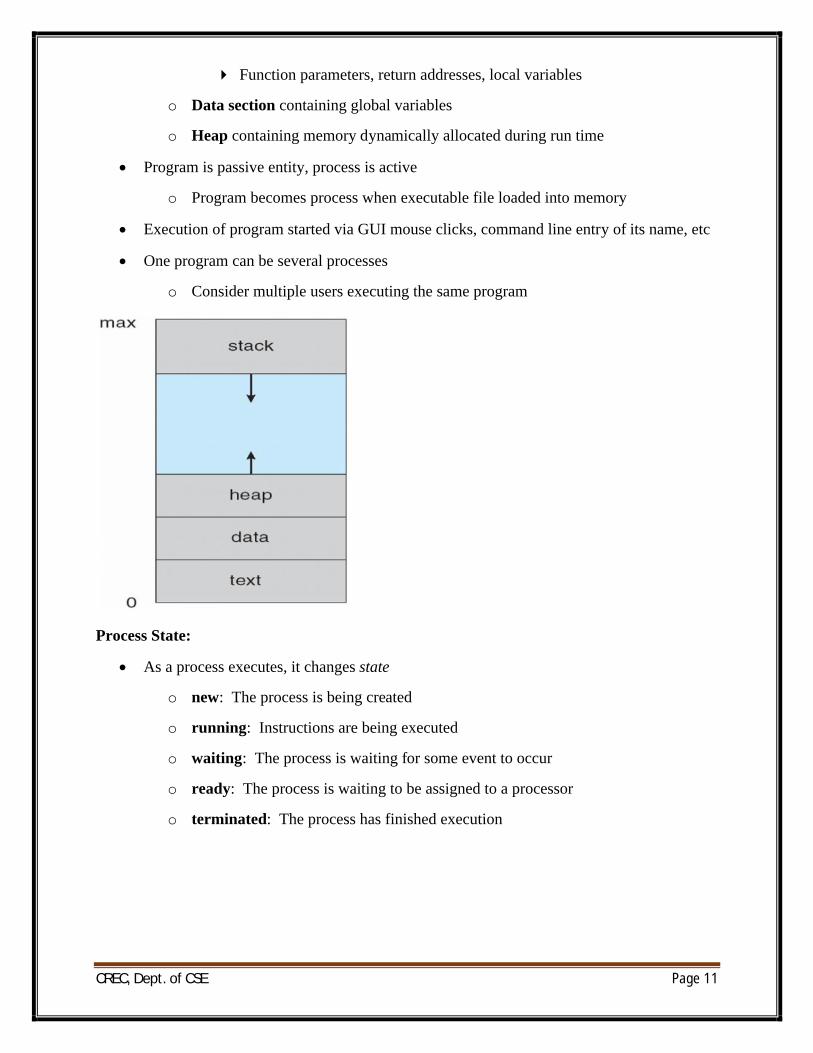
Process State:
∑ As a process executes, it changes state
o new: The process is being created
o running: Instructions are being executed
o waiting: The process is waiting for some event to occur
o ready: The process is waiting to be assigned to a processor
o terminated: The process has finished execution
CREC, Dept. of CSE Page 12
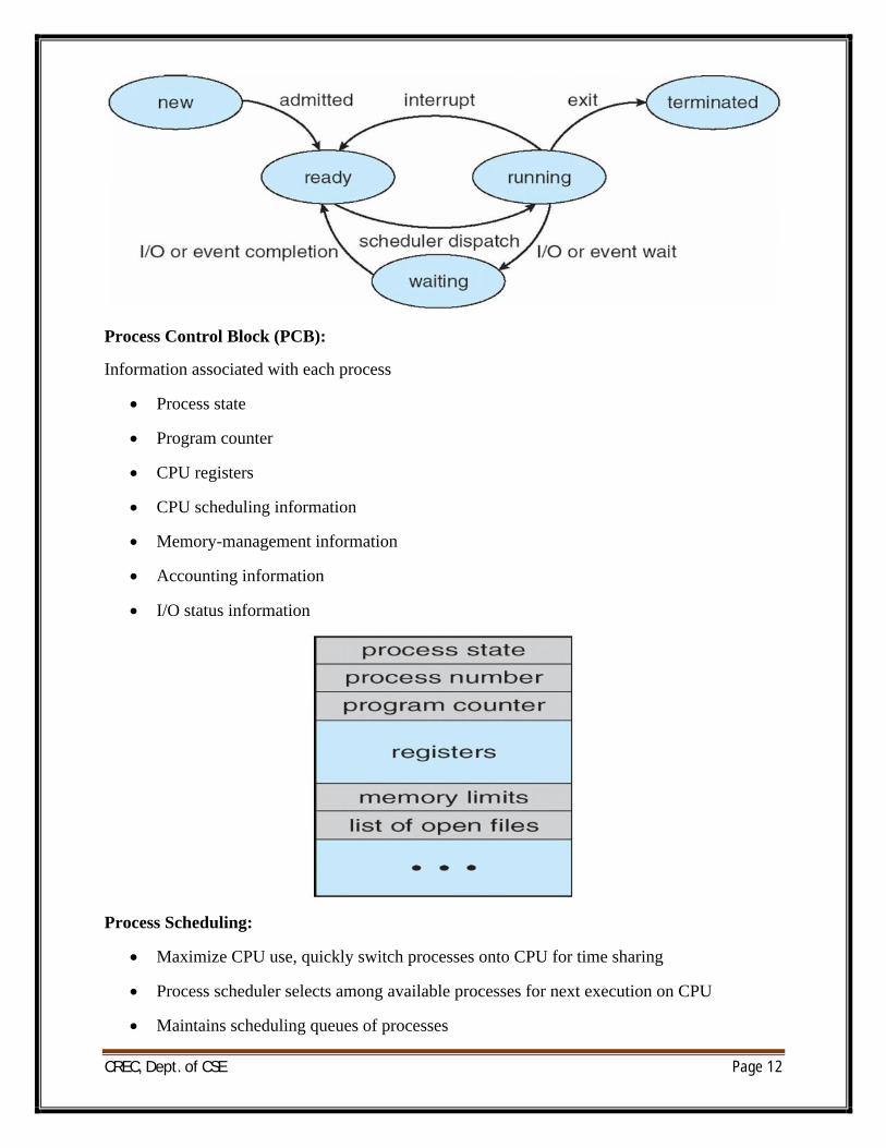
Process Control Block (PCB):
Information associated with each process
∑ Process state
∑ Program counter
∑ CPU registers
∑ CPU scheduling information
∑ Memory-management information
∑ Accounting information
∑ I/O status information
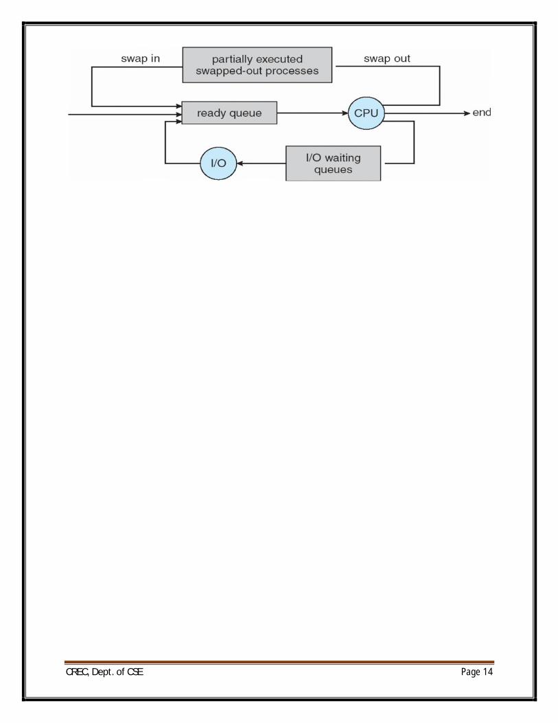
Process Scheduling:
∑ Maximize CPU use, quickly switch processes onto CPU for time sharing
∑ Process scheduler selects among available processes for next execution on CPU
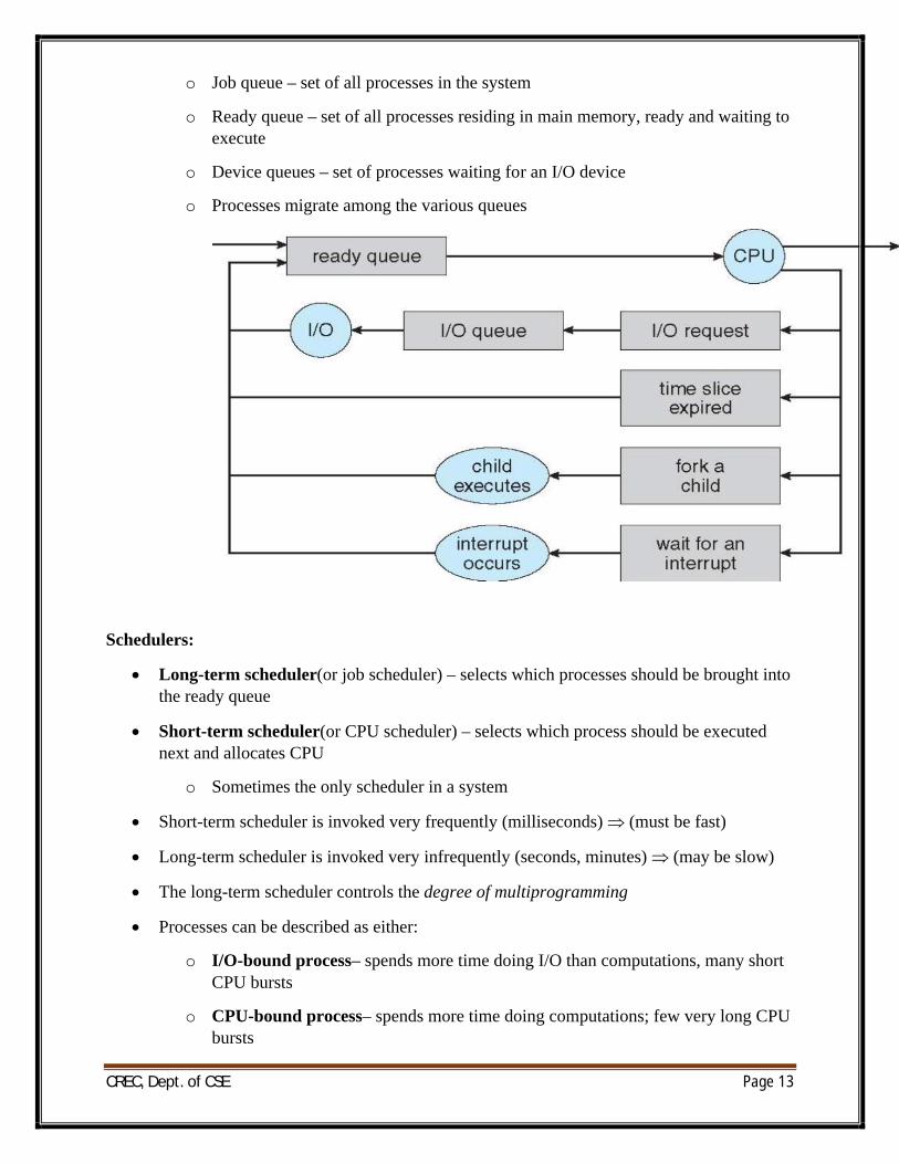
∑ Maintains scheduling queues of processes
CREC, Dept. of CSE Page 13
o Job queue – set of all processes in the system
o Ready queue – set of all processes residing in main memory, ready and waiting to execute
o Device queues – set of processes waiting for an I/O device
o Processes migrate among the various queues
Schedulers:
∑ Long-term scheduler(or job scheduler) – selects which processes should be brought into the ready queue
∑ Short-term scheduler(or CPU scheduler) – selects which process should be executed next and allocates CPU
o Sometimes the only scheduler in a system
∑ Short-term scheduler is invoked very frequently (milliseconds) (must be fast)
∑ Long-term scheduler is invoked very infrequently (seconds, minutes) (may be slow)
∑ The long-term scheduler controls the degree of multiprogramming
∑ Processes can be described as either:
o I/O-bound process– spends more time doing I/O than computations, many short CPU bursts
o CPU-bound process– spends more time doing computations; few very long CPU bursts
CREC, Dept. of CSE Page 14
CREC, Dept. of CSE Page 15
UNIT-2
THREADS, PROCESS SYNCHRONISATON, CPUSCHEDULING
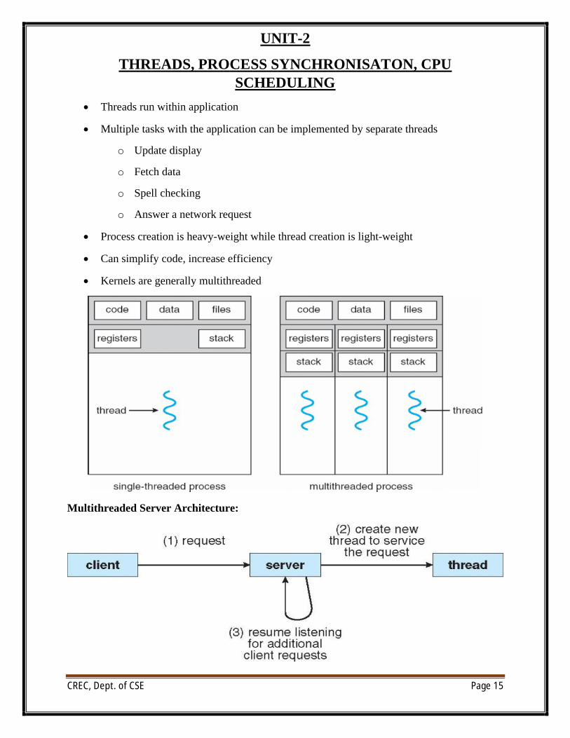
∑ Threads run within application
∑ Multiple tasks with the application can be implemented by separate threads
o Update display
o Fetch data
o Spell checking
o Answer a network request
∑ Process creation is heavy-weight while thread creation is light-weight
∑ Can simplify code, increase efficiency
∑ Kernels are generally multithreaded
Multithreaded Server Architecture:
CREC, Dept. of CSE Page 16
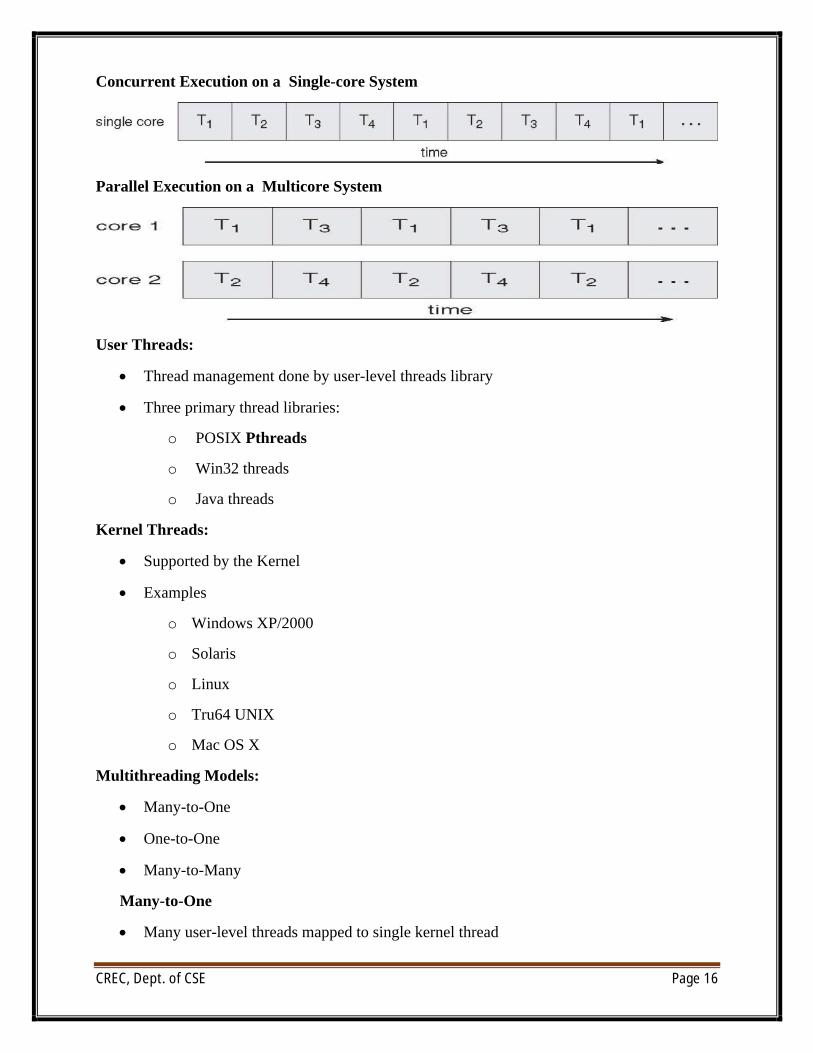
Concurrent Execution on a Single-core System
Parallel Execution on a Multicore System
User Threads:
∑ Thread management done by user-level threads library
∑ Three primary thread libraries:
o POSIX Pthreads
o Win32 threads
o Java threads
Kernel Threads:
∑ Supported by the Kernel
∑ Examples
o Windows XP/2000
o Solaris
o Linux
o Tru64 UNIX
o Mac OS X
Multithreading Models:
∑ Many-to-One
∑ One-to-One
∑ Many-to-Many
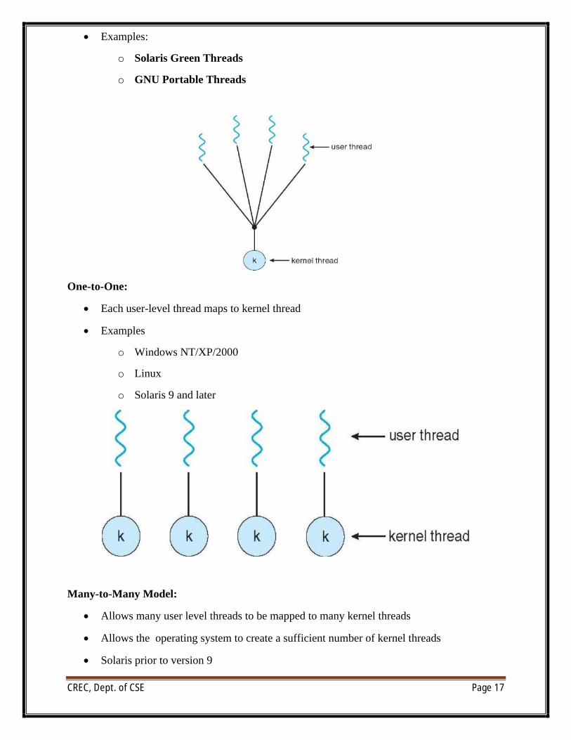
Many-to-One
∑ Many user-level threads mapped to single kernel thread
CREC, Dept. of CSE Page 17
∑ Examples:
o Solaris Green Threads
o GNU Portable Threads
One-to-One:
∑ Each user-level thread maps to kernel thread
∑ Examples
o Windows NT/XP/2000
o Linux
o Solaris 9 and later
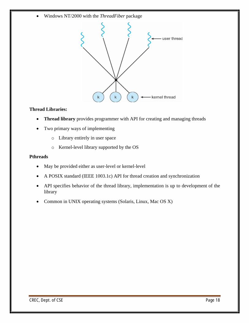
Many-to-Many Model:
∑ Allows many user level threads to be mapped to many kernel threads
∑ Allows the operating system to create a sufficient number of kernel threads
∑ Solaris prior to version 9
CREC, Dept. of CSE Page 18
∑ Windows NT/2000 with the ThreadFiber package
Thread Libraries:
∑ Thread library provides programmer with API for creating and managing threads
∑ Two primary ways of implementing
o Library entirely in user space
o Kernel-level library supported by the OS
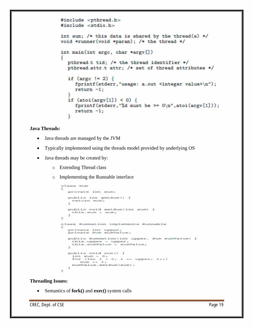
Pthreads
∑ May be provided either as user-level or kernel-level
∑ A POSIX standard (IEEE 1003.1c) API for thread creation and synchronization
∑ API specifies behavior of the thread library, implementation is up to development of the library
∑ Common in UNIX operating systems (Solaris, Linux, Mac OS X)
CREC, Dept. of CSE Page 19
Java Threads:
∑ Java threads are managed by the JVM
∑ Typically implemented using the threads model provided by underlying OS
∑ Java threads may be created by:
o Extending Thread class
o Implementing the Runnable interface
Threading Issues:
∑ Semantics of fork() and exec() system calls
CREC, Dept. of CSE Page 20
∑ Thread cancellation of target thread
o Asynchronous or deferred
o Signal handling
o Synchronous and asynchronous
∑ Thread pools
∑ Thread-specific data
n Create Facility needed for data private to thread
∑ Scheduler activations
Thread Cancellation:
∑ Terminating a thread before it has finished
∑ Two general approaches:
o Asynchronous cancellation terminates the target thread immediately.
o Deferred cancellation allows the target thread to periodically check if it should be cancelled.
Thread Pools:
∑ Create a number of threads in a pool where they await work
∑ Advantages:
o Usually slightly faster to service a request with an existing thread than create a new thread
o Allows the number of threads in the application(s) to be bound to the size of the pool
Scheduler Activations:
∑ Both M:M and Two-level models require communication to maintain the appropriate number of kernel threads allocated to the application
∑ Scheduler activations provide upcalls - a communication mechanism from the kernel to the thread library
∑ This communication allows an application to maintain the correct number kernel threads
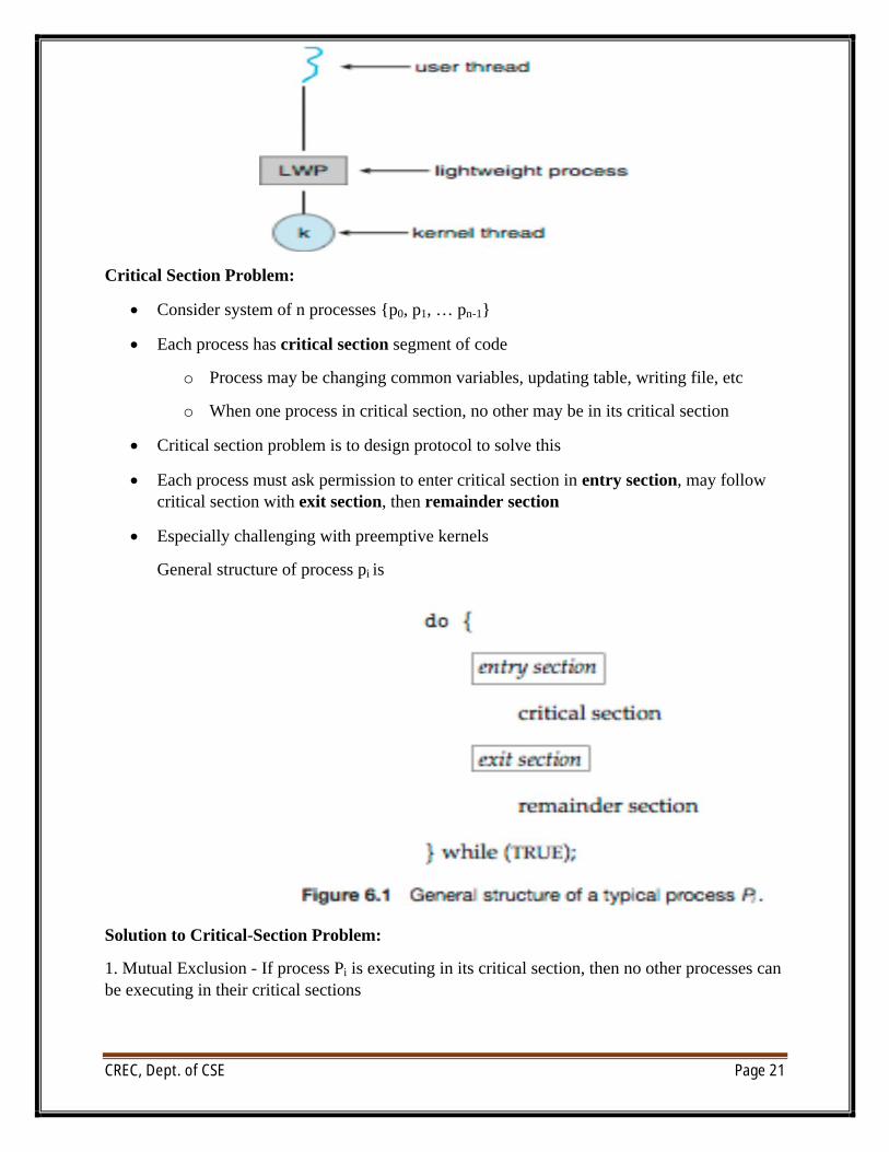
Lightweight Processes
CREC, Dept. of CSE Page 21
Critical Section Problem:
∑ Consider system of n processes {p0, p1, … pn-1}
∑ Each process has critical section segment of code
o Process may be changing common variables, updating table, writing file, etc
o When one process in critical section, no other may be in its critical section
∑ Critical section problem is to design protocol to solve this
∑ Each process must ask permission to enter critical section in entry section, may follow critical section with exit section, then remainder section
∑ Especially challenging with preemptive kernels
General structure of process pi is
Solution to Critical-Section Problem:
1. Mutual Exclusion - If process Pi is executing in its critical section, then no other processes can be executing in their critical sections
CREC, Dept. of CSE Page 22
2. Progress - If no process is executing in its critical section and there exist some processes that wish to enter their critical section, then the selection of the processes that will enter the critical section next cannot be postponed indefinitely
3. Bounded Waiting - A bound must exist on the number of times that other processes are allowed to enter their critical sections after a process has made a request to enter its critical section and before that request is granted
ó Assume that each process executes at a nonzero speed
ó No assumption concerning relative speed of the n processes
Peterson’s Solution:
∑ Two process solution
∑ Assume that the LOAD and STORE instructions are atomic; that is, cannot be interrupted
∑ The two processes share two variables:
o intturn;
o Boolean flag[2]
o The variable turn indicates whose turn it is to enter the critical section
∑ The flag array is used to indicate if a process is ready to enter the critical section. flag[i]= true implies that process Pi is ready!
Algorithm for Process Pi
do {
flag[i] = TRUE;
turn = j;
while (flag[j] && turn == j);
critical section
flag[i] = FALSE;
remainder section
} while (TRUE);
∑ Provable that
1. Mutual exclusion is preserved
2. Progress requirement is satisfied
3. Bounded-waiting requirement is met
Synchronization Hardware:
∑ Many systems provide hardware support for critical section code
CREC, Dept. of CSE Page 23
∑ Uniprocessors – could disable interrupts
o Currently running code would execute without preemption
o Generally too inefficient on multiprocessor systems
4 Operating systems using this not broadly scalable
4 Modern machines provide special atomic hardware instructions
4 Atomic = non-interruptable
o Either test memory word and set value
o Or swap contents of two memory words
do {
acquire lock
critical section
release lock
remainder section
} while (TRUE);
Semaphore:
∑ Synchronization tool that does not require busy waiting
∑ Semaphore S – integer variable
∑ Two standard operations modify S: wait() and signal()
o Originally called P() andV()
∑ Less complicated
∑ Can only be accessed via two indivisible (atomic) operations
wait (S) {
while S <= 0 ; // no-op
S--; }
signal (S) {
S++;
}
Semaphore as General Synchronization Tool
∑ Counting semaphore – integer value can range over an unrestricted domain
CREC, Dept. of CSE Page 24
∑ Binary semaphore – integer value can range only between 0 and 1; can be simpler to implement
l Also known as mutex locks
∑ Can implement a counting semaphore S as a binary semaphore
∑ Provides mutual exclusion
Semaphore mutex; // initialized to 1
do {
wait (mutex);
// Critical Section
signal (mutex);
// remainder section
} while (TRUE);
Semaphore Implementation
∑ Must guarantee that no two processes can execute wait () and signal () on the same semaphore at the same time
∑ Thus, implementation becomes the critical section problem where the wait and signal code are placed in the crtical section
o Could now have busy waiting in critical section implementation
4 But implementation code is short
4 Little busy waiting if critical section rarely occupied
4 Note that applications may spend lots of time in critical sections and therefore this is not a good solution
Deadlock and Starvation
∑ Deadlock – two or more processes are waiting indefinitely for an event that can be caused by only one of the waiting processes
∑ Let S and Q be two semaphores initialized to 1
P0P1
wait (S); wait (Q);
wait (Q); wait (S);
. .
CREC, Dept. of CSE Page 25
. .
signal (S); signal (Q);
signal (Q); signal (S);
∑ Starvation – indefinite blocking
o A process may never be removed from the semaphore queue in which it is suspended
∑ Priority Inversion – Scheduling problem when lower-priority process holds a lock needed by higher-priority process
o Solved via priority-inheritance protocol
Classical Problems of Synchronization:
∑ Classical problems used to test newly-proposed synchronization schemes
o Bounded-Buffer Problem
o Readers and Writers Problem
o Dining-Philosophers Problem
Bounded-Buffer Problem
∑ N buffers, each can hold one item
∑ Semaphore mutex initialized to the value 1
∑ Semaphore full initialized to the value 0
∑ Semaphore empty initialized to the value N
∑ The structure of the producer process
do {
// produce an item in nextp
wait (empty);
wait (mutex);
// add the item to the buffer
signal (mutex);
signal (full);
} while (TRUE);
CREC, Dept. of CSE Page 26
∑ The structure of the consumer process
do {
wait (full);
wait (mutex);
// remove an item from buffer to nextc
signal (mutex);
signal (empty);
// consume the item in nextc
} while (TRUE);
Readers-Writers Problem:
∑ A data set is shared among a number of concurrent processes
o Readers – only read the data set; they do not perform any updates
o Writers – can both read and write
∑ Problem – allow multiple readers to read at the same time
o Only one single writer can access the shared data at the same time
o Several variations of how readers and writers are treated – all involve priorities
∑ Shared Data
o Data set
o Semaphore mutex initialized to 1
o Semaphore wrt initialized to 1
o Integer readcount initialized to 0
∑ The structure of a writer process
do {
wait (wrt) ;
// writing is performed
signal (wrt) ;
} while (TRUE);
∑ The structure of a reader process
do {
CREC, Dept. of CSE Page 27
wait (mutex) ;
readcount ++ ;
if (readcount == 1)
wait (wrt) ;
signal (mutex)
// reading is performed
wait (mutex) ;
readcount - - ;
if (readcount == 0)
signal (wrt) ;
signal (mutex) ;
} while (TRUE);
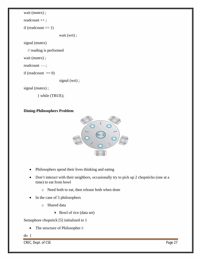
Dining-Philosophers Problem
∑ Philosophers spend their lives thinking and eating
∑ Don’t interact with their neighbors, occasionally try to pick up 2 chopsticks (one at a time) to eat from bowl
o Need both to eat, then release both when done
∑ In the case of 5 philosophers
o Shared data
4 Bowl of rice (data set)
Semaphore chopstick [5] initialized to 1
∑ The structure of Philosopher i:
do {
CREC, Dept. of CSE Page 28
wait ( chopstick[i] );
wait ( chopStick[ (i + 1) % 5] );
// eat
signal ( chopstick[i] );
signal (chopstick[ (i + 1) % 5] );
// think
} while (TRUE);
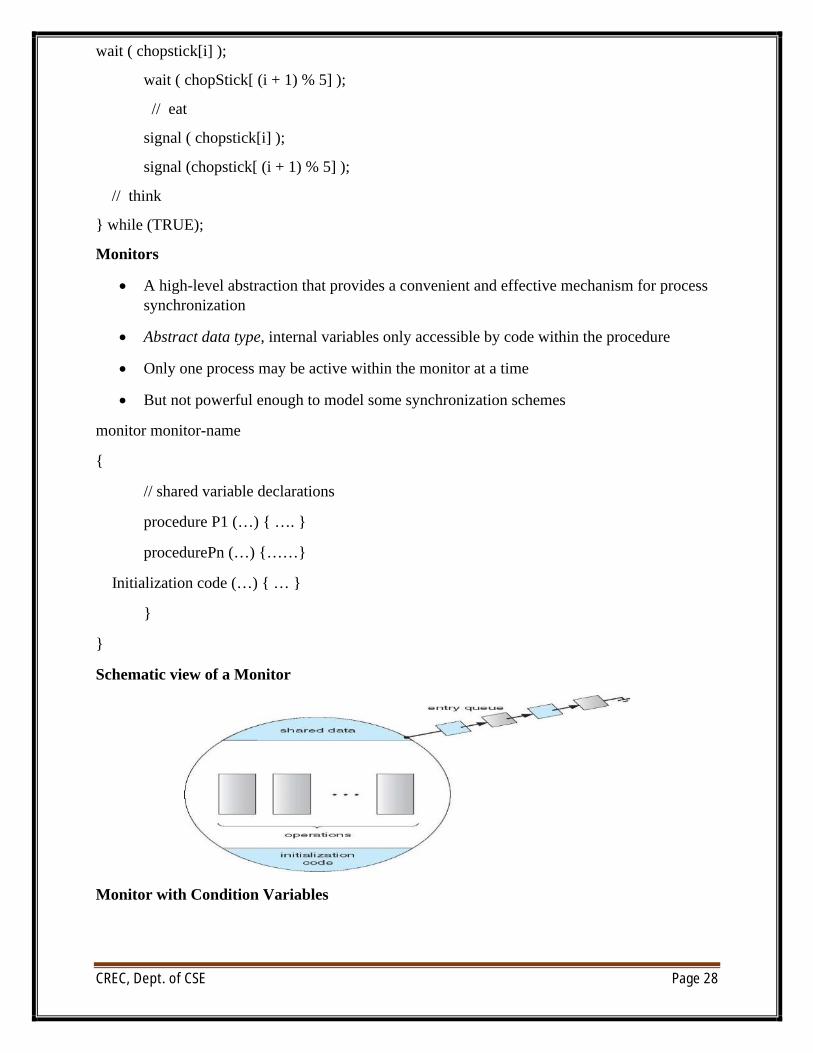
Monitors
∑ A high-level abstraction that provides a convenient and effective mechanism for process synchronization
∑ Abstract data type, internal variables only accessible by code within the procedure
∑ Only one process may be active within the monitor at a time
∑ But not powerful enough to model some synchronization schemes
monitor monitor-name
{
// shared variable declarations
procedure P1 (…) { …. }
procedurePn (…) {……}
Initialization code (…) { … }
}
}
Schematic view of a Monitor
Monitor with Condition Variables
CREC, Dept. of CSE Page 29
Scheduling Criteria:
∑ CPU utilization – keep the CPU as busy as possible
∑ Throughput – # of processes that complete their execution per time unit
∑ Turnaround time – amount of time to execute a particular process
∑ Waiting time – amount of time a process has been waiting in the ready queue
∑ Response time – amount of time it takes from when a request was submitted until the first response is produced, not output (for time-sharing environment)
Scheduling Algorithm Optimization Criteria
∑ Max CPU utilization
∑ Max throughput
∑ Min turnaround time
∑ Min waiting time
∑ Min response time
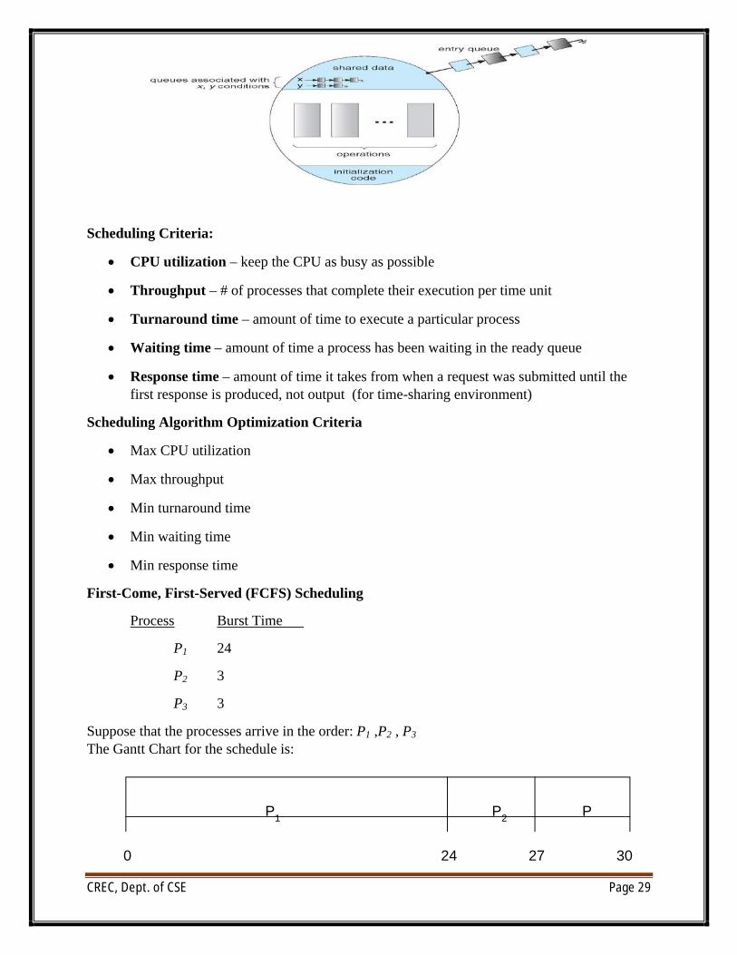
First-Come, First-Served (FCFS) Scheduling
Process Burst Time
P1 24
P2 3
P3 3
Suppose that the processes arrive in the order: P1 ,P2 , P3
The Gantt Chart for the schedule is:
P1
P2
P
24 27 300
CREC, Dept. of CSE Page 30
Waiting time for P1 = 0; P2 = 24; P3 = 27
∑ Average waiting time: (0 + 24 + 27)/3 = 17
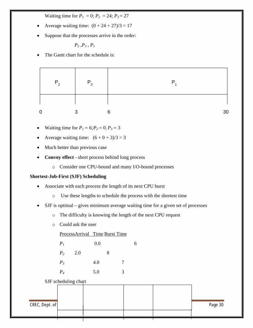
∑ Suppose that the processes arrive in the order:
P2 ,P3 , P1
∑ The Gantt chart for the schedule is:
∑ Waiting time for P1 = 6;P2 = 0; P3 = 3
∑ Average waiting time: (6 + 0 + 3)/3 = 3
∑ Much better than previous case
∑ Convoy effect - short process behind long process
o Consider one CPU-bound and many I/O-bound processes
Shortest-Job-First (SJF) Scheduling
∑ Associate with each process the length of its next CPU burst
o Use these lengths to schedule the process with the shortest time
∑ SJF is optimal – gives minimum average waiting time for a given set of processes
o The difficulty is knowing the length of the next CPU request
o Could ask the user
ProcessArrival Time Burst Time
P1 0.0 6
P2 2.0 8
P3 4.0 7
P4 5.0 3
SJF scheduling chart
P1
P3
P2
63 300
CREC, Dept. of CSE Page 31
∑ Average waiting time = (3 + 16 + 9 + 0) / 4 = 7
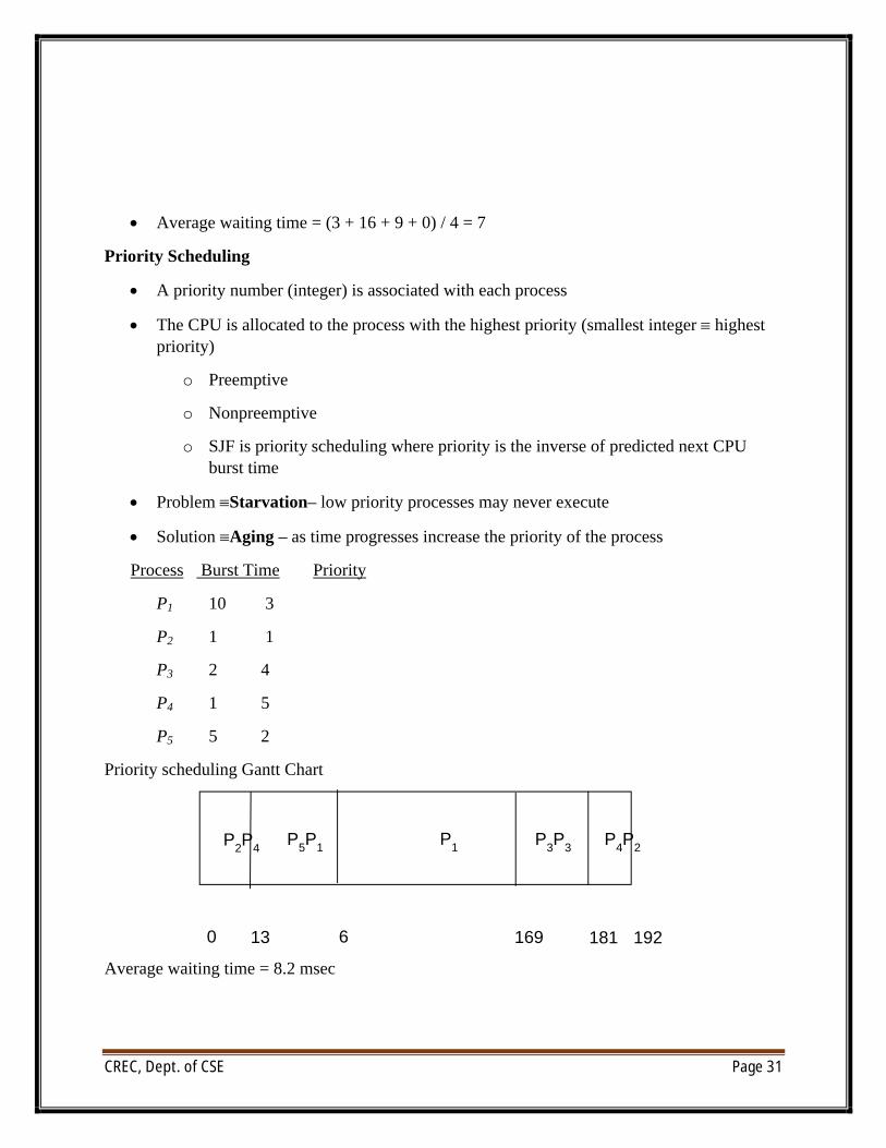
Priority Scheduling
∑ A priority number (integer) is associated with each process
∑ The CPU is allocated to the process with the highest priority (smallest integer ∫ highest priority)
o Preemptive
o Nonpreemptive
o SJF is priority scheduling where priority is the inverse of predicted next CPU burst time
∑ Problem ∫Starvation– low priority processes may never execute
∑ Solution ∫Aging – as time progresses increase the priority of the process
Process Burst Time Priority
P1 10 3
P2 1 1
P3 2 4
P4 1 5
P5 5 2
Priority scheduling Gantt Chart
Average waiting time = 8.2 msec
P2P4
P3P3
P5P1
13 1810 169
P4P2
1926
P1
CREC, Dept. of CSE Page 32
UNIT-3
Virtual Memory, Main Memory, Deadlocks
∑ Program must be brought (from disk) into memory and placed within a process for it to be run
∑ Main memory and registers are only storage CPU can access directly
∑ Memory unit only sees a stream of addresses + read requests, or address + data and write requests
∑ Register access in one CPU clock (or less)
∑ Main memory can take many cycles
∑ Cache sits between main memory and CPU registers
∑ Protection of memory required to ensure correct operation
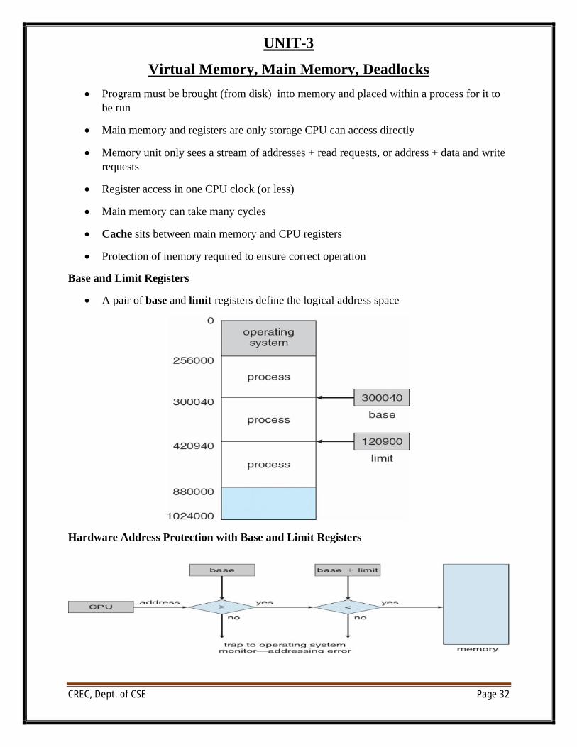
Base and Limit Registers
∑ A pair of base and limit registers define the logical address space
Hardware Address Protection with Base and Limit Registers
CREC, Dept. of CSE Page 33
Logical vs. Physical Address Space
∑ The concept of a logical address space that is bound to a separate physical address spaceis central to proper memory management
o Logical address – generated by the CPU; also referred to as virtual address
o Physical address – address seen by the memory unit
o Logical and physical addresses are the same in compile-time and load-time address-binding schemes; logical (virtual) and physical addresses differ in execution-time address-binding scheme
∑ Logical address space is the set of all logical addresses generated by a program
∑ Physical address space is the set of all physical addresses generated by a program
Memory-Management Unit (MMU)
∑ Hardware device that at run time maps virtual to physical address
∑ Many methods possible, covered in the rest of this chapter
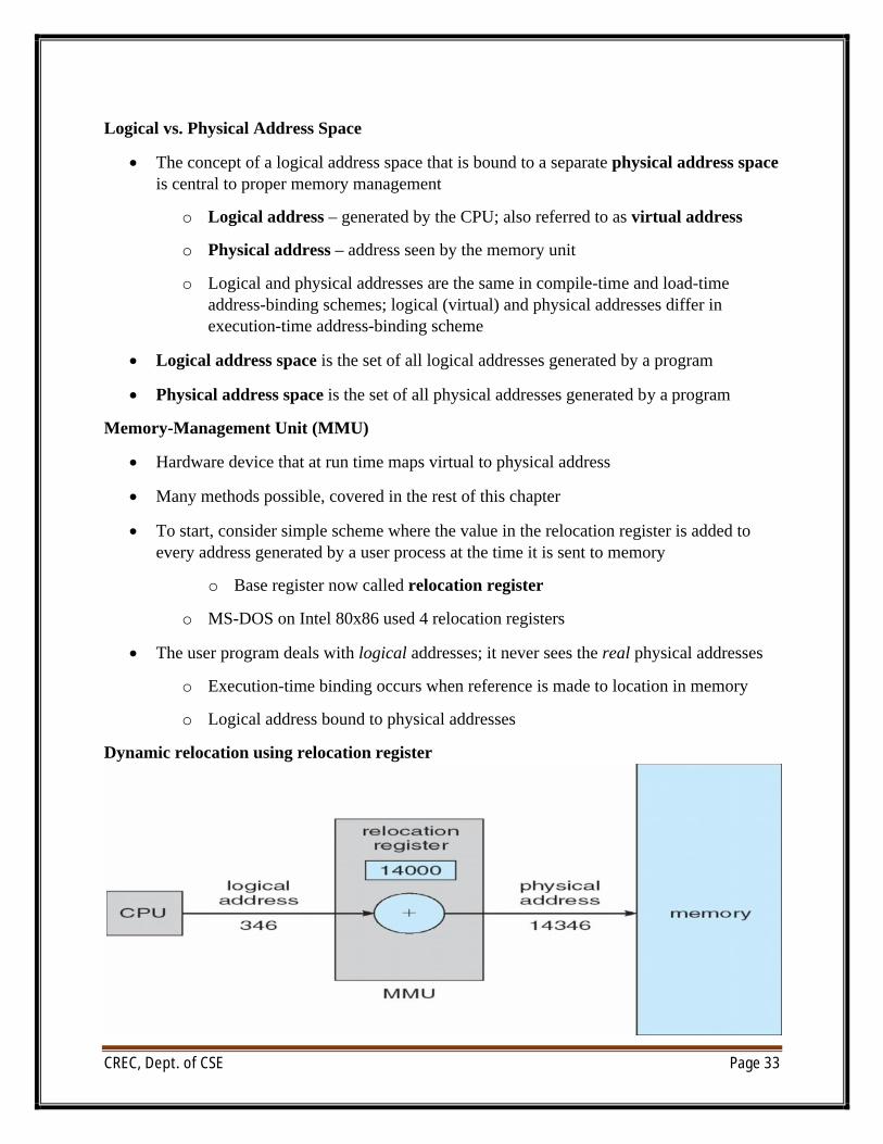
∑ To start, consider simple scheme where the value in the relocation register is added to every address generated by a user process at the time it is sent to memory
o Base register now called relocation register
o MS-DOS on Intel 80x86 used 4 relocation registers
∑ The user program deals with logical addresses; it never sees the real physical addresses
o Execution-time binding occurs when reference is made to location in memory
o Logical address bound to physical addresses
Dynamic relocation using relocation register
CREC, Dept. of CSE Page 34
Dynamic Loading
∑ Routine is not loaded until it is called
∑ Better memory-space utilization; unused routine is never loaded
∑ All routines kept on disk in relocatable load format
∑ Useful when large amounts of code are needed to handle infrequently occurring cases
∑ No special support from the operating system is required
o Implemented through program design
o OS can help by providing libraries to implement dynamic loading
Dynamic Linking
∑ Static linking – system libraries and program code combined by the loader into the binary program image
∑ Dynamic linking –linking postponed until execution time
∑ Small piece of code, stub, used to locate the appropriate memory-resident library routine
∑ Stub replaces itself with the address of the routine, and executes the routine
∑ Operating system checks if routine is in processes’ memory address
o If not in address space, add to address space
∑ Dynamic linking is particularly useful for libraries
∑ System also known as shared libraries
∑ Consider applicability to patching system libraries
o Versioning may be needed
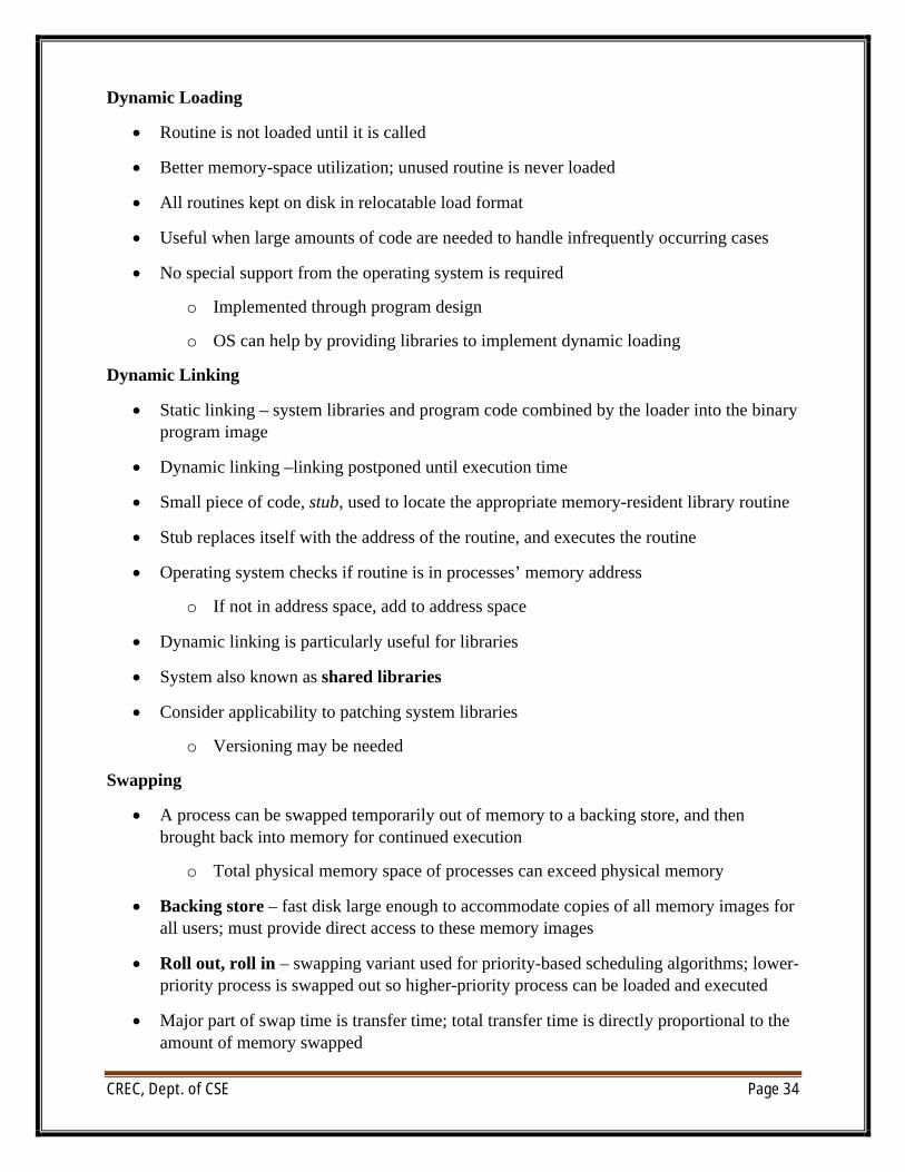
Swapping
∑ A process can be swapped temporarily out of memory to a backing store, and then brought back into memory for continued execution
o Total physical memory space of processes can exceed physical memory
∑ Backing store – fast disk large enough to accommodate copies of all memory images for all users; must provide direct access to these memory images
∑ Roll out, roll in – swapping variant used for priority-based scheduling algorithms; lower-priority process is swapped out so higher-priority process can be loaded and executed
∑ Major part of swap time is transfer time; total transfer time is directly proportional to the amount of memory swapped
CREC, Dept. of CSE Page 35
∑ System maintains a ready queue of ready-to-run processes which have memory images on disk
∑ Does the swapped out process need to swap back in to same physical addresses?
∑ Depends on address binding method
o Plus consider pending I/O to / from process memory space
∑ Modified versions of swapping are found on many systems (i.e., UNIX, Linux, and Windows)
o Swapping normally disabled
o Started if more than threshold amount of memory allocated
o Disabled again once memory demand reduced below threshold
Contiguous Allocation
∑ Main memory usually into two partitions:
o Resident operating system, usually held in low memory with interrupt vector
o User processes then held in high memory
o Each process contained in single contiguous section of memory
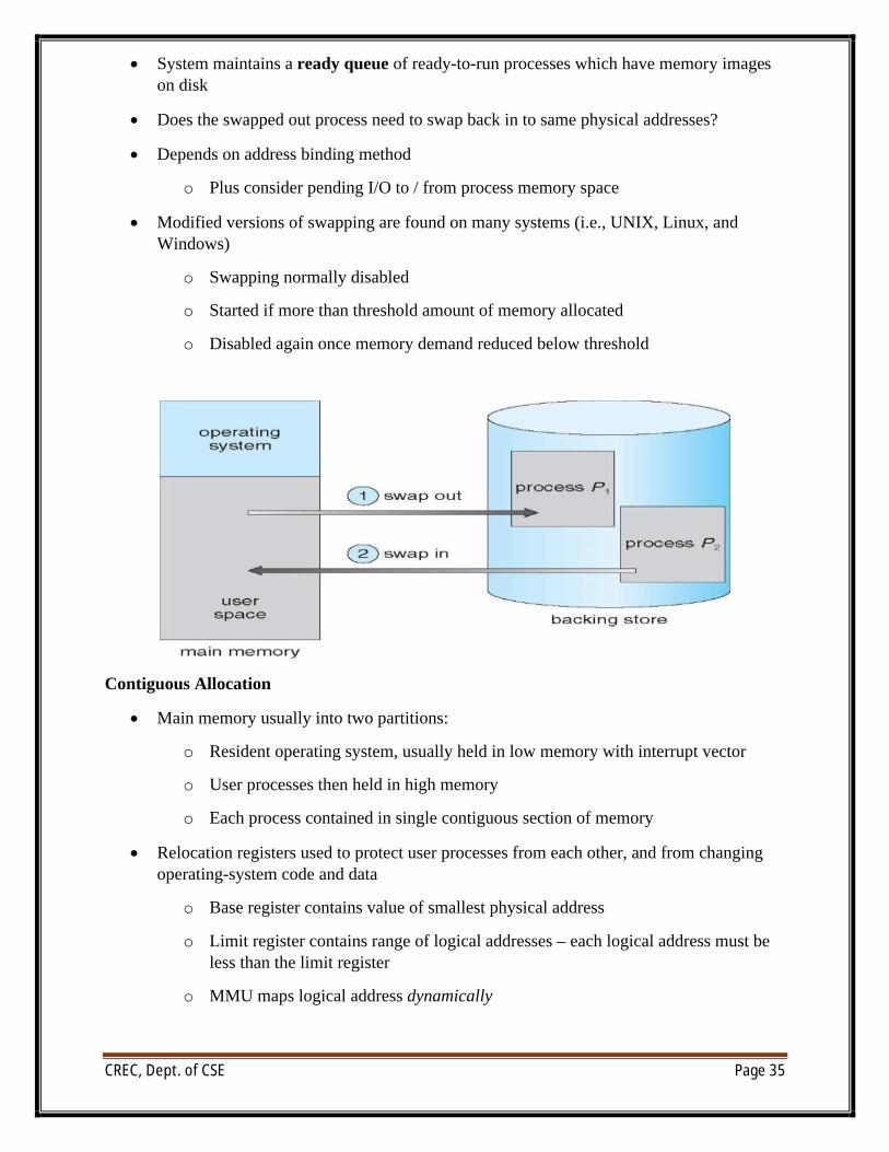
∑ Relocation registers used to protect user processes from each other, and from changing operating-system code and data
o Base register contains value of smallest physical address
o Limit register contains range of logical addresses – each logical address must be less than the limit register
o MMU maps logical address dynamically
CREC, Dept. of CSE Page 36
o Can then allow actions such as kernel code being transient and kernel changing size
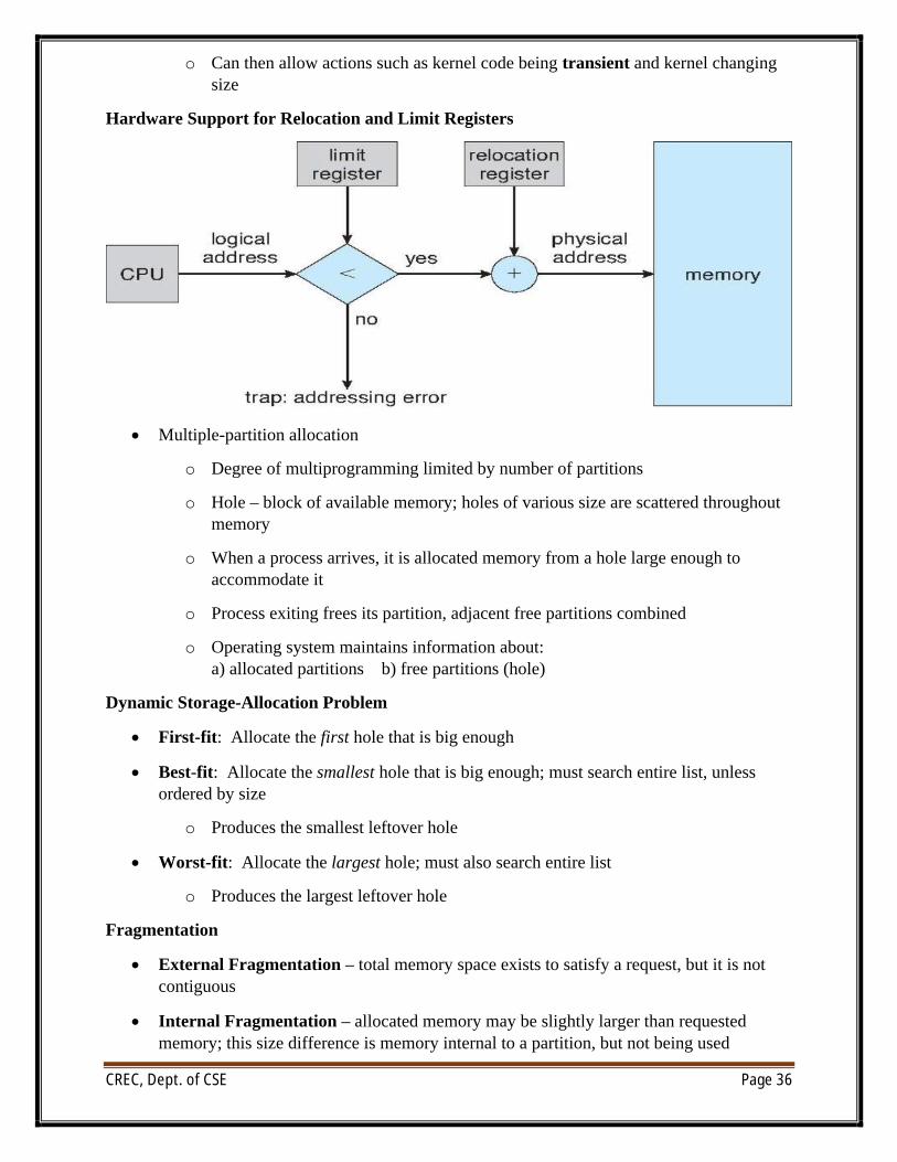
Hardware Support for Relocation and Limit Registers
∑ Multiple-partition allocation
o Degree of multiprogramming limited by number of partitions
o Hole – block of available memory; holes of various size are scattered throughout memory
o When a process arrives, it is allocated memory from a hole large enough to accommodate it
o Process exiting frees its partition, adjacent free partitions combined
o Operating system maintains information about:a) allocated partitions b) free partitions (hole)
Dynamic Storage-Allocation Problem
∑ First-fit: Allocate the first hole that is big enough
∑ Best-fit: Allocate the smallest hole that is big enough; must search entire list, unless ordered by size
o Produces the smallest leftover hole
∑ Worst-fit: Allocate the largest hole; must also search entire list
o Produces the largest leftover hole
Fragmentation
∑ External Fragmentation – total memory space exists to satisfy a request, but it is not contiguous
∑ Internal Fragmentation – allocated memory may be slightly larger than requested memory; this size difference is memory internal to a partition, but not being used
CREC, Dept. of CSE Page 37
∑ First fit analysis reveals that given N blocks allocated, 0.5 N blocks lost to fragmentation
o 1/3 may be unusable ->50-percent rule
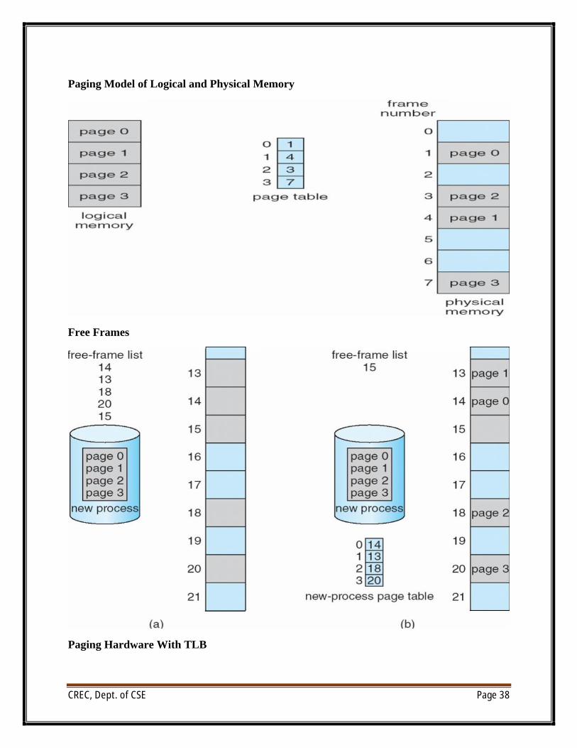
Paging
∑ Physical address space of a process can be noncontiguous; process is allocated physical memory whenever the latter is available
∑ Divide physical memory into fixed-sized blocks called frames
o Size is power of 2, between 512 bytes and 16 Mbytes
∑ Divide logical memory into blocks of same size called pages
∑ Keep track of all free frames
∑ To run a program of size N pages, need to find N free frames and load program
∑ Set up a page table to translate logical to physical addresses
∑ Backing store likewise split into pages
∑ Still have Internal fragmentation
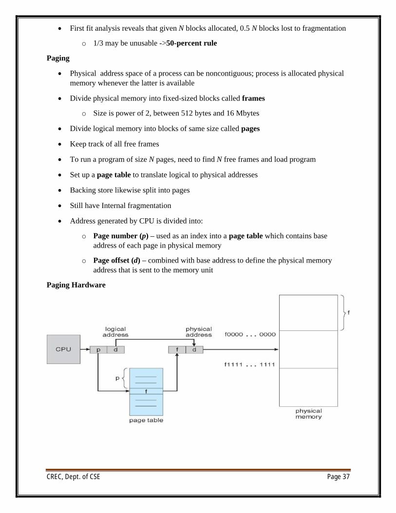
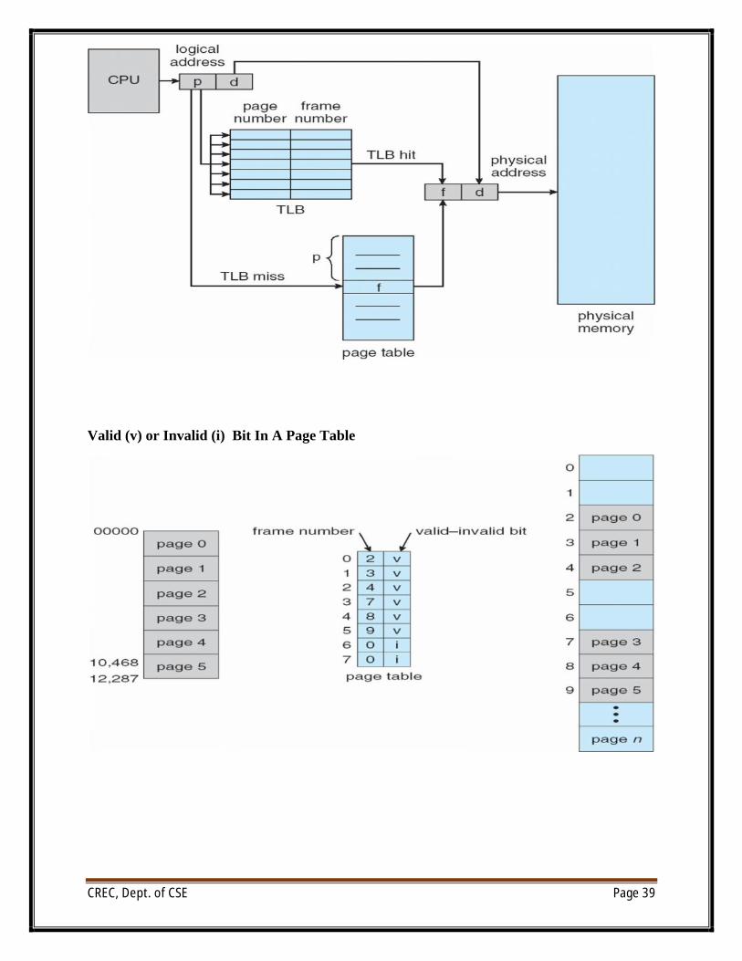
∑ Address generated by CPU is divided into:
o Page number (p) – used as an index into a page table which contains base address of each page in physical memory
o Page offset (d) – combined with base address to define the physical memory address that is sent to the memory unit
Paging Hardware
CREC, Dept. of CSE Page 38
Paging Model of Logical and Physical Memory
Free Frames
Paging Hardware With TLB
CREC, Dept. of CSE Page 39
Valid (v) or Invalid (i) Bit In A Page Table
CREC, Dept. of CSE Page 40
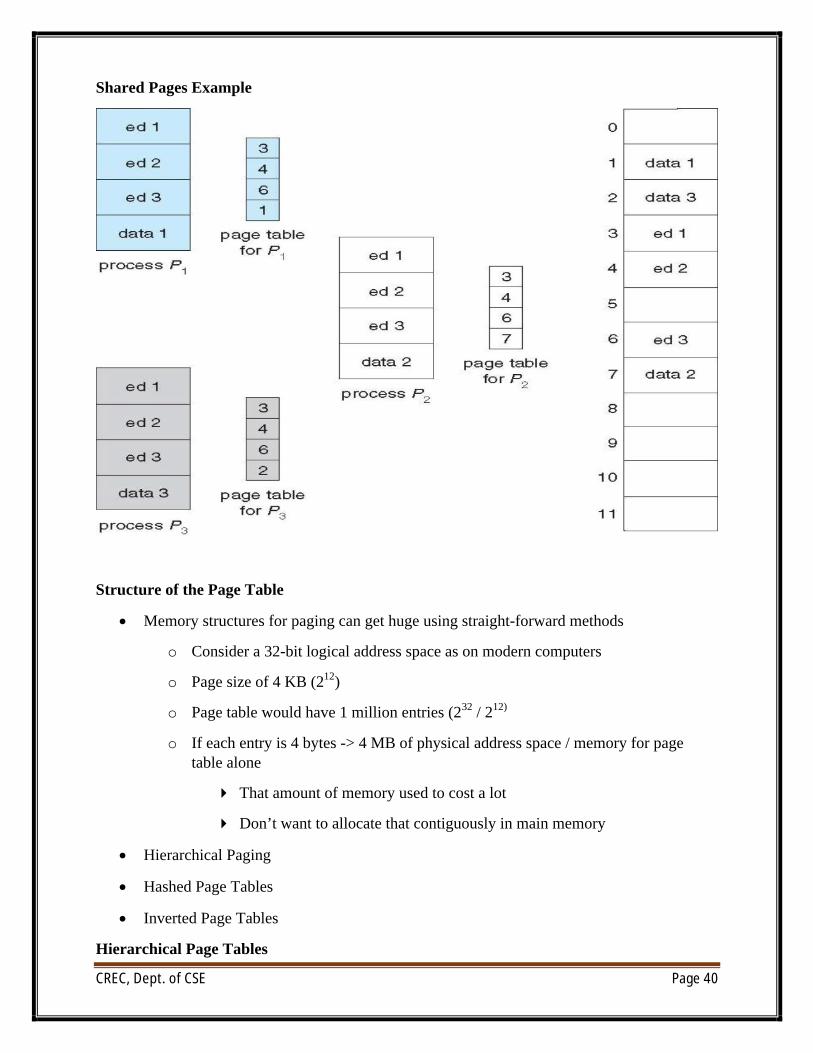
Shared Pages Example
Structure of the Page Table
∑ Memory structures for paging can get huge using straight-forward methods
o Consider a 32-bit logical address space as on modern computers
o Page size of 4 KB (212)
o Page table would have 1 million entries (232 / 212)
o If each entry is 4 bytes -> 4 MB of physical address space / memory for page table alone
4 That amount of memory used to cost a lot
4 Don’t want to allocate that contiguously in main memory
∑ Hierarchical Paging
∑ Hashed Page Tables
∑ Inverted Page Tables
Hierarchical Page Tables
CREC, Dept. of CSE Page 41
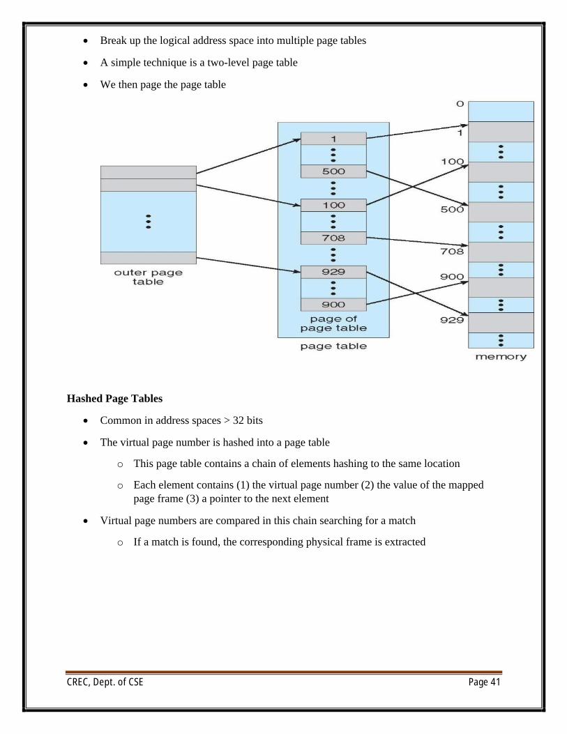
∑ Break up the logical address space into multiple page tables
∑ A simple technique is a two-level page table
∑ We then page the page table
Hashed Page Tables
∑ Common in address spaces > 32 bits
∑ The virtual page number is hashed into a page table
o This page table contains a chain of elements hashing to the same location
o Each element contains (1) the virtual page number (2) the value of the mapped page frame (3) a pointer to the next element
∑ Virtual page numbers are compared in this chain searching for a match
o If a match is found, the corresponding physical frame is extracted
CREC, Dept. of CSE Page 42
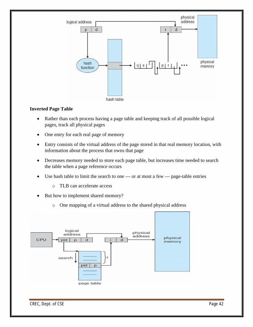
Inverted Page Table
∑ Rather than each process having a page table and keeping track of all possible logical pages, track all physical pages
∑ One entry for each real page of memory
∑ Entry consists of the virtual address of the page stored in that real memory location, with information about the process that owns that page
∑ Decreases memory needed to store each page table, but increases time needed to search the table when a page reference occurs
∑ Use hash table to limit the search to one — or at most a few — page-table entries
o TLB can accelerate access
∑ But how to implement shared memory?
o One mapping of a virtual address to the shared physical address
CREC, Dept. of CSE Page 43
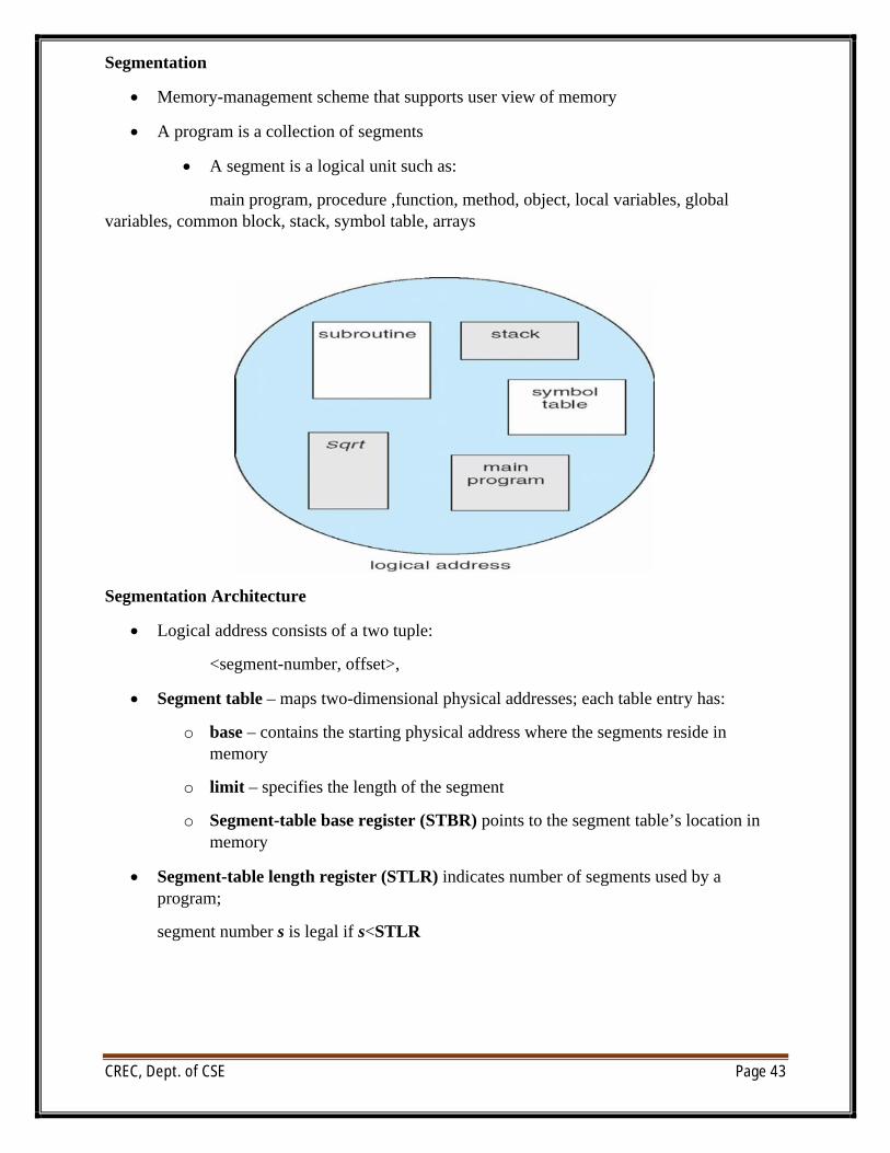
Segmentation
∑ Memory-management scheme that supports user view of memory
∑ A program is a collection of segments
∑ A segment is a logical unit such as:
main program, procedure ,function, method, object, local variables, global variables, common block, stack, symbol table, arrays
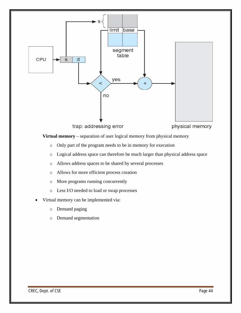
Segmentation Architecture
∑ Logical address consists of a two tuple:
<segment-number, offset>,
∑ Segment table – maps two-dimensional physical addresses; each table entry has:
o base – contains the starting physical address where the segments reside in memory
o limit – specifies the length of the segment
o Segment-table base register (STBR) points to the segment table’s location in memory
∑ Segment-table length register (STLR) indicates number of segments used by a program;
segment number s is legal if s<STLR
CREC, Dept. of CSE Page 44
Virtual memory – separation of user logical memory from physical memory
o Only part of the program needs to be in memory for execution
o Logical address space can therefore be much larger than physical address space
o Allows address spaces to be shared by several processes
o Allows for more efficient process creation
o More programs running concurrently
o Less I/O needed to load or swap processes
∑ Virtual memory can be implemented via:
o Demand paging
o Demand segmentation
CREC, Dept. of CSE Page 45
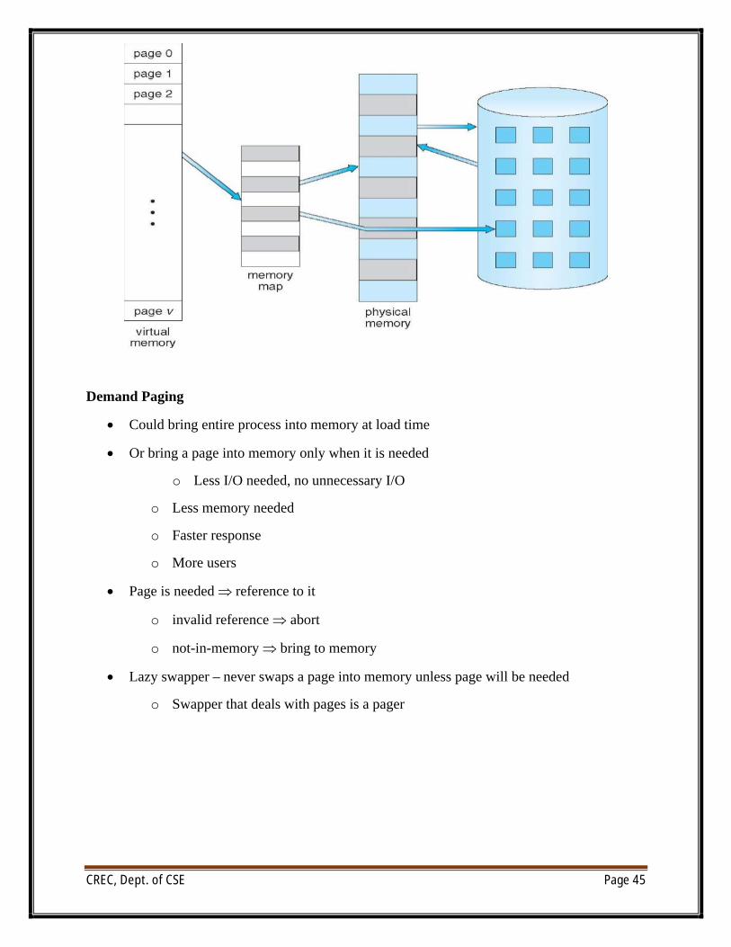
Demand Paging
∑ Could bring entire process into memory at load time
∑ Or bring a page into memory only when it is needed
o Less I/O needed, no unnecessary I/O
o Less memory needed
o Faster response
o More users
∑ Page is needed reference to it
o invalid reference abort
o not-in-memory bring to memory
∑ Lazy swapper – never swaps a page into memory unless page will be needed
o Swapper that deals with pages is a pager
CREC, Dept. of CSE Page 46
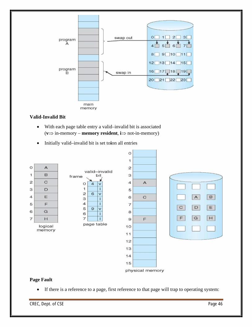
Valid-Invalid Bit
∑ With each page table entry a valid–invalid bit is associated(v in-memory – memory resident, i not-in-memory)
∑ Initially valid–invalid bit is set toion all entries
Page Fault
∑ If there is a reference to a page, first reference to that page will trap to operating system:
CREC, Dept. of CSE Page 47
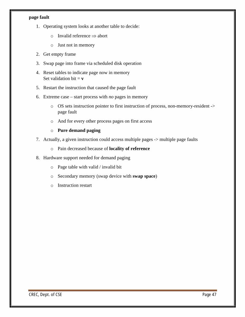
page fault
1. Operating system looks at another table to decide:
o Invalid reference abort
o Just not in memory
2. Get empty frame
3. Swap page into frame via scheduled disk operation
4. Reset tables to indicate page now in memorySet validation bit = v
5. Restart the instruction that caused the page fault
6. Extreme case – start process with no pages in memory
o OS sets instruction pointer to first instruction of process, non-memory-resident -> page fault
o And for every other process pages on first access
o Pure demand paging
7. Actually, a given instruction could access multiple pages -> multiple page faults
o Pain decreased because of locality of reference
8. Hardware support needed for demand paging
o Page table with valid / invalid bit
o Secondary memory (swap device with swap space)
o Instruction restart
CREC, Dept. of CSE Page 48
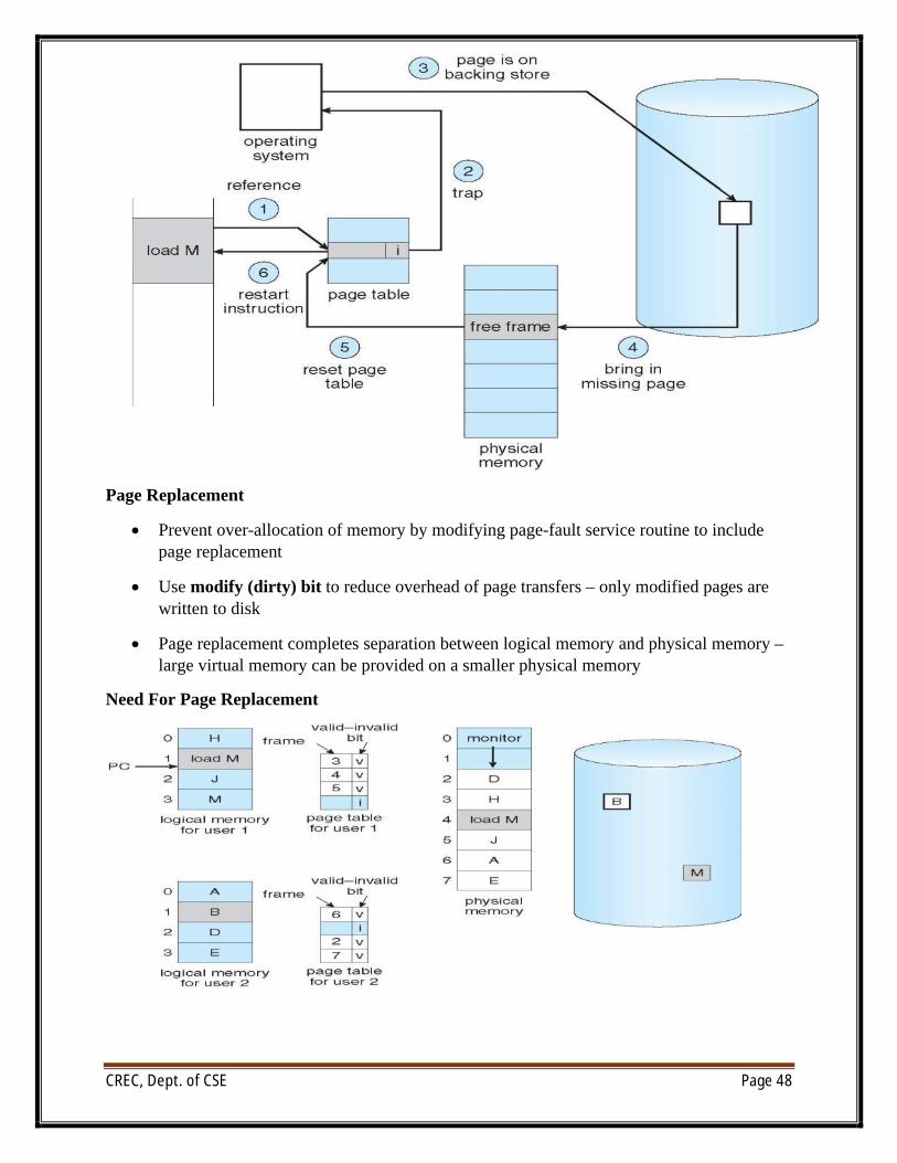
Page Replacement
∑ Prevent over-allocation of memory by modifying page-fault service routine to include page replacement
∑ Use modify (dirty) bit to reduce overhead of page transfers – only modified pages are written to disk
∑ Page replacement completes separation between logical memory and physical memory –large virtual memory can be provided on a smaller physical memory
Need For Page Replacement
CREC, Dept. of CSE Page 49
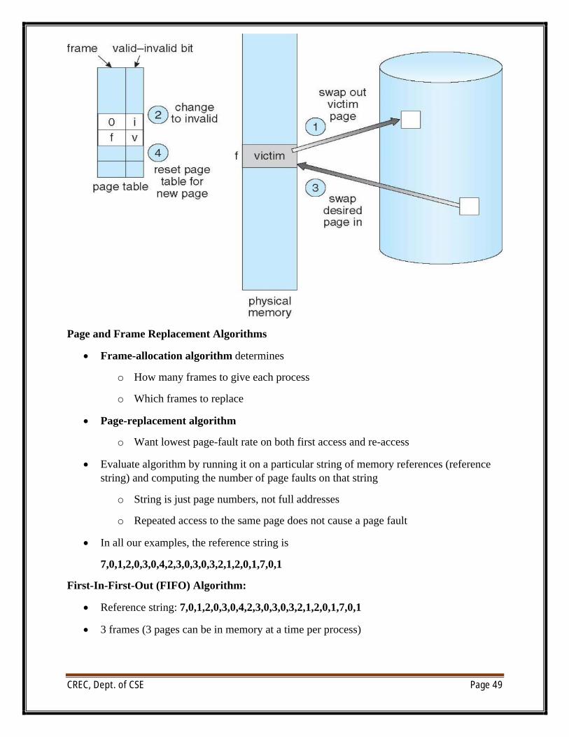
Page and Frame Replacement Algorithms
∑ Frame-allocation algorithm determines
o How many frames to give each process
o Which frames to replace
∑ Page-replacement algorithm
o Want lowest page-fault rate on both first access and re-access
∑ Evaluate algorithm by running it on a particular string of memory references (reference string) and computing the number of page faults on that string
o String is just page numbers, not full addresses
o Repeated access to the same page does not cause a page fault
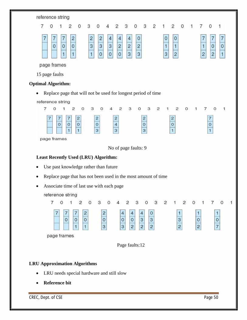
∑ In all our examples, the reference string is
7,0,1,2,0,3,0,4,2,3,0,3,0,3,2,1,2,0,1,7,0,1
First-In-First-Out (FIFO) Algorithm:
∑ Reference string: 7,0,1,2,0,3,0,4,2,3,0,3,0,3,2,1,2,0,1,7,0,1
∑ 3 frames (3 pages can be in memory at a time per process)
CREC, Dept. of CSE Page 50
15 page faults
Optimal Algorithm:
∑ Replace page that will not be used for longest period of time
No of page faults: 9
Least Recently Used (LRU) Algorithm:
∑ Use past knowledge rather than future
∑ Replace page that has not been used in the most amount of time
∑ Associate time of last use with each page
Page faults:12
LRU Approximation Algorithms
∑ LRU needs special hardware and still slow
∑ Reference bit
CREC, Dept. of CSE Page 51
o With each page associate a bit, initially = 0
o When page is referenced bit set to 1
o Replace any with reference bit = 0 (if one exists)
4 We do not know the order, however
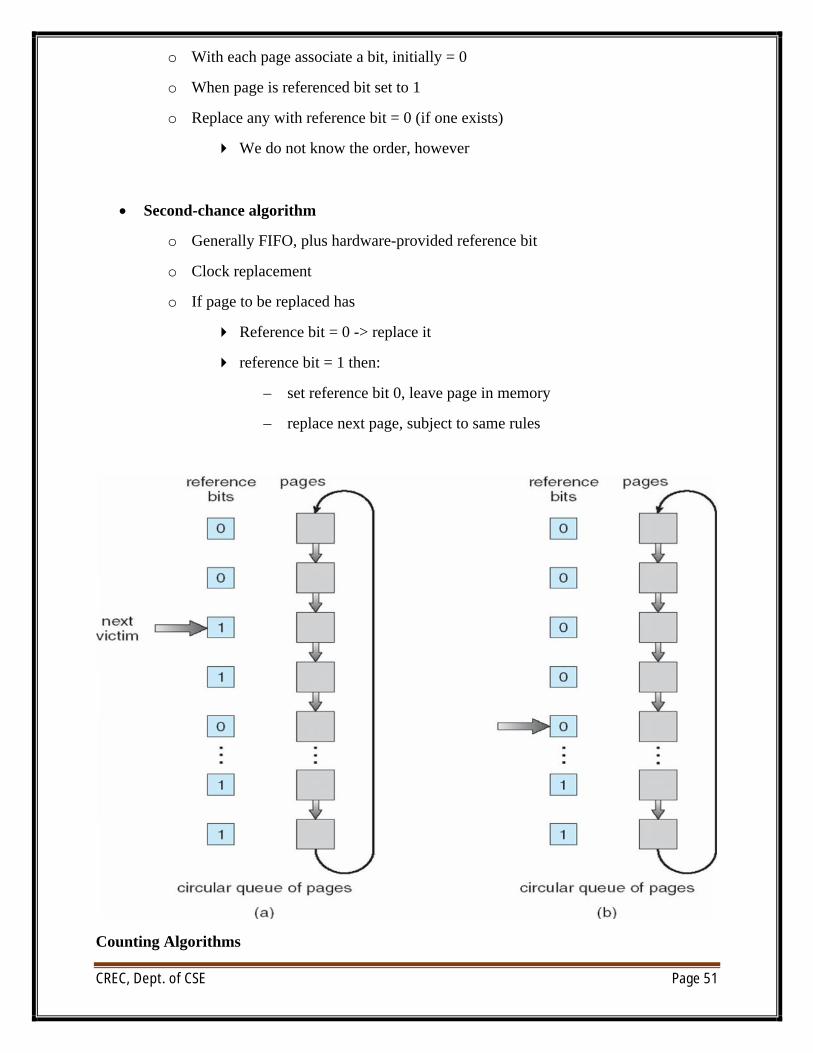
∑ Second-chance algorithm
o Generally FIFO, plus hardware-provided reference bit
o Clock replacement
o If page to be replaced has
4 Reference bit = 0 -> replace it
4 reference bit = 1 then:
– set reference bit 0, leave page in memory
– replace next page, subject to same rules
Counting Algorithms
CREC, Dept. of CSE Page 52
∑ Keep a counter of the number of references that have been made to each page
l Not common
∑ LFU Algorithm: replaces page with smallest count
∑ MFU Algorithm: based on the argument that the page with the smallest count was probably just brought in and has yet to be used
Applications and Page Replacement
∑ All of these algorithms have OS guessing about future page access
∑ Some applications have better knowledge – i.e. databases
∑ Memory intensive applications can cause double buffering
l OS keeps copy of page in memory as I/O buffer
l Application keeps page in memory for its own work
∑ Operating system can given direct access to the disk, getting out of the way of the applications
l Raw disk mode
∑ Bypasses buffering, locking, etc
Allocation of Frames
∑ Each process needs minimum number of frames
∑ Example: IBM 370 – 6 pages to handle SS MOVE instruction:
o instruction is 6 bytes, might span 2 pages
o 2 pages to handle from
o 2 pages to handle to
∑ Maximum of course is total frames in the system
∑ Two major allocation schemes
o fixed allocation
o priority allocation
∑ Many variations
Fixed Allocation
∑ Equal allocation – For example, if there are 100 frames (after allocating frames for the OS) and 5 processes, give each process 20 frames
o Keep some as free frame buffer pool
CREC, Dept. of CSE Page 53
∑ Proportional allocation – Allocate according to the size of process
o Dynamic as degree of multiprogramming, process sizes change
mS
spa
m
sS
ps
iii
i
ii
¥
Â
for allocation
framesofnumber total
processofsize
5964137
127
564137
10
127
10
64
2
1
2
1
ª¥
ª¥
a
a
s
s
m
Priority Allocation
∑ Use a proportional allocation scheme using priorities rather than size
∑ If process Pi generates a page fault,
o select for replacement one of its frames
o select for replacement a frame from a process with lower priority number
Global vs. Local Allocation
∑ Global replacement – process selects a replacement frame from the set of all frames; one process can take a frame from another
o But then process execution time can vary greatly
o But greater throughput so more common
∑ Local replacement – each process selects from only its own set of allocated frames
o More consistent per-process performance
o But possibly underutilized memory
Thrashing
∑ If a process does not have “enough” pages, the page-fault rate is very high
o Page fault to get page
o Replace existing frame
o But quickly need replaced frame back
o This leads to:
4 Low CPU utilization
4 Operating system thinking that it needs to increase the degree of multiprogramming
4 Another process added to the system
CREC, Dept. of CSE Page 54
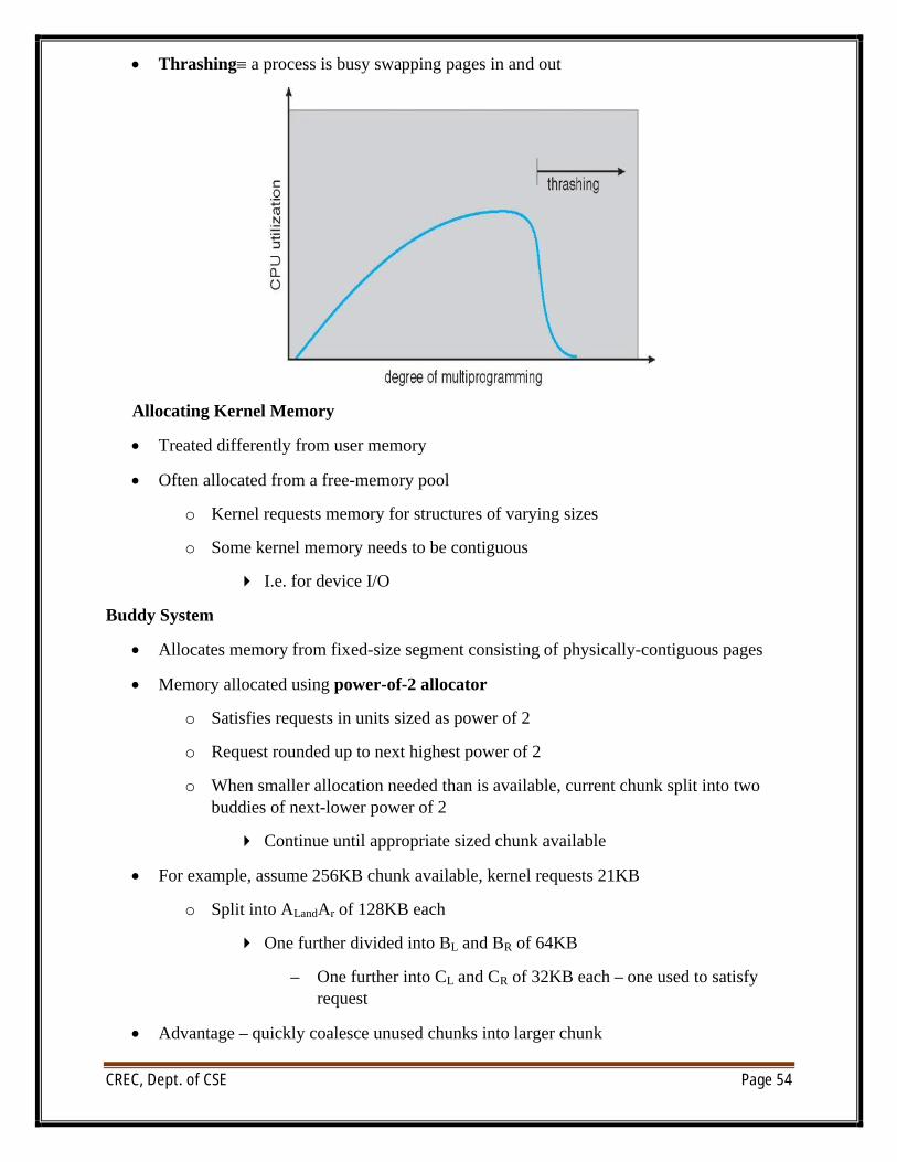
∑ Thrashing∫ a process is busy swapping pages in and out
Allocating Kernel Memory
∑ Treated differently from user memory
∑ Often allocated from a free-memory pool
o Kernel requests memory for structures of varying sizes
o Some kernel memory needs to be contiguous
4 I.e. for device I/O
Buddy System
∑ Allocates memory from fixed-size segment consisting of physically-contiguous pages
∑ Memory allocated using power-of-2 allocator
o Satisfies requests in units sized as power of 2
o Request rounded up to next highest power of 2
o When smaller allocation needed than is available, current chunk split into two buddies of next-lower power of 2
4 Continue until appropriate sized chunk available
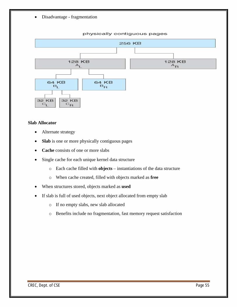
∑ For example, assume 256KB chunk available, kernel requests 21KB
o Split into ALandAr of 128KB each
4 One further divided into BL and BR of 64KB
– One further into CL and CR of 32KB each – one used to satisfy request
∑ Advantage – quickly coalesce unused chunks into larger chunk
CREC, Dept. of CSE Page 55
∑ Disadvantage - fragmentation
Slab Allocator
∑ Alternate strategy
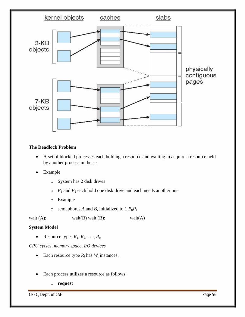
∑ Slab is one or more physically contiguous pages
∑ Cache consists of one or more slabs
∑ Single cache for each unique kernel data structure
o Each cache filled with objects – instantiations of the data structure
o When cache created, filled with objects marked as free
∑ When structures stored, objects marked as used
∑ If slab is full of used objects, next object allocated from empty slab
o If no empty slabs, new slab allocated
o Benefits include no fragmentation, fast memory request satisfaction
CREC, Dept. of CSE Page 56
The Deadlock Problem
∑ A set of blocked processes each holding a resource and waiting to acquire a resource held by another process in the set
∑ Example
o System has 2 disk drives
o P1 and P2 each hold one disk drive and each needs another one
o Example
o semaphores A and B, initialized to 1 P0P1
wait (A); wait(B) wait (B); wait(A)
System Model
∑ Resource types R1, R2, . . ., Rm
CPU cycles, memory space, I/O devices
∑ Each resource type Ri has Wi instances.
∑ Each process utilizes a resource as follows:
o request
CREC, Dept. of CSE Page 57
o use
o release
Deadlock Characterization
Deadlock can arise if four conditions hold simultaneously.
∑ Mutual exclusion: only one process at a time can use a resource
∑ Hold and wait: a process holding at least one resource is waiting to acquire additional resources held by other processes
∑ No preemption: a resource can be released only voluntarily by the process holding it, after that process has completed its task
∑ Circular wait: there exists a set {P0, P1, …, Pn} of waiting processes such that P0 is waiting for a resource that is held by P1, P1 is waiting for a resource that is held by
P2, …,Pn–1 is waiting for a resource that is held by Pn, and Pn is waiting for a resource that is held by P0.
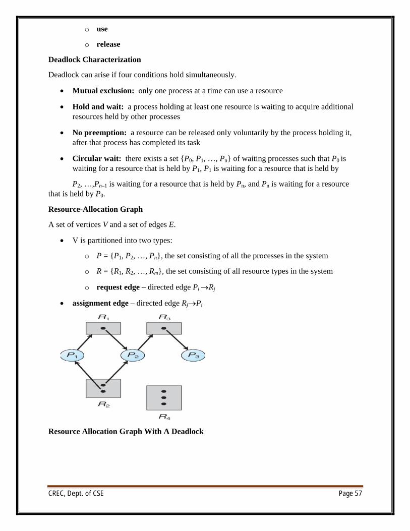
Resource-Allocation Graph
A set of vertices V and a set of edges E.
∑ V is partitioned into two types:
o P = {P1, P2, …, Pn}, the set consisting of all the processes in the system
o R = {R1, R2, …, Rm}, the set consisting of all resource types in the system
o request edge – directed edge Pi ÆRj
∑ assignment edge – directed edge RjÆPi
Resource Allocation Graph With A Deadlock
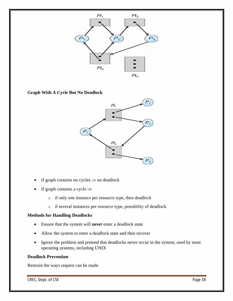
CREC, Dept. of CSE Page 58
Graph With A Cycle But No Deadlock
∑ If graph contains no cycles no deadlock
∑ If graph contains a cycle
o if only one instance per resource type, then deadlock
o if several instances per resource type, possibility of deadlock
Methods for Handling Deadlocks
∑ Ensure that the system will never enter a deadlock state
∑ Allow the system to enter a deadlock state and then recover
∑ Ignore the problem and pretend that deadlocks never occur in the system; used by most operating systems, including UNIX
Deadlock Prevention
Restrain the ways request can be made
CREC, Dept. of CSE Page 59
∑ Mutual Exclusion – not required for sharable resources; must hold for nonsharable resources
∑ Hold and Wait – must guarantee that whenever a process requests a resource, it does not hold any other resources
o Require process to request and be allocated all its resources before it begins execution, or allow process to request resources only when the process has none
o Low resource utilization; starvation possible
∑ No Preemption –
o If a process that is holding some resources requests another resource that cannot be immediately allocated to it, then all resources currently being held are released
o Preempted resources are added to the list of resources for which the process is waiting
o Process will be restarted only when it can regain its old resources, as well as the new ones that it is requesting
∑ Circular Wait – impose a total ordering of all resource types, and require that each process requests resources in an increasing order of enumeration
Deadlock Avoidance
Requires that the system has some additional a priori information available
∑ Simplest and most useful model requires that each process declare the maximum numberof resources of each type that it may need
∑ The deadlock-avoidance algorithm dynamically examines the resource-allocation state to ensure that there can never be a circular-wait condition
∑ Resource-allocation state is defined by the number of available and allocated resources, and the maximum demands of the processes
Safe State
∑ When a process requests an available resource, system must decide if immediate allocation leaves the system in a safe state
∑ System is in safe state if there exists a sequence <P1, P2, …, Pn> of ALL the processes in the systems such that for each Pi, the resources that Pi can still request can be satisfied by currently available resources + resources held by all the Pj, with j <I
∑ That is:
o If Pi resource needs are not immediately available, then Pi can wait until all Pjhave finished
o When Pj is finished, Pi can obtain needed resources, execute, return allocated resources, and terminate
CREC, Dept. of CSE Page 60
o When Pi terminates, Pi +1 can obtain its needed resources, and so on
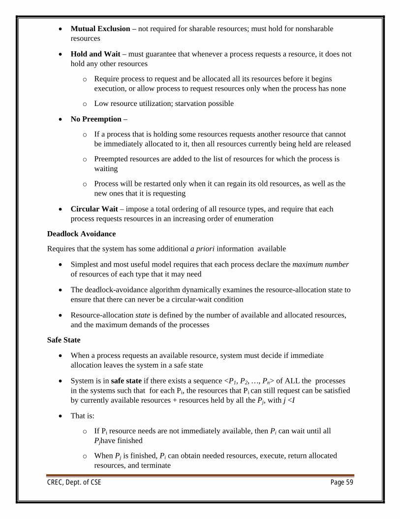
∑ If a system is in safe state no deadlocks
∑ If a system is in unsafe state possibility of deadlock
Avoidance ensure that a system will never enter an unsafe state
Avoidance algorithms
∑ Single instance of a resource type
o Use a resource-allocation graph
∑ Multiple instances of a resource type
o Use the banker’s algorithm
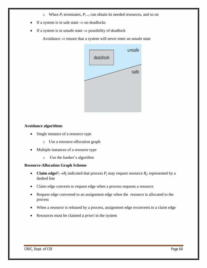
Resource-Allocation Graph Scheme
∑ Claim edgePiÆRj indicated that process Pj may request resource Rj; represented by a dashed line
∑ Claim edge converts to request edge when a process requests a resource
∑ Request edge converted to an assignment edge when the resource is allocated to the process
∑ When a resource is released by a process, assignment edge reconverts to a claim edge
∑ Resources must be claimed a priori in the system
CREC, Dept. of CSE Page 61
Unsafe State In Resource-Allocation Graph
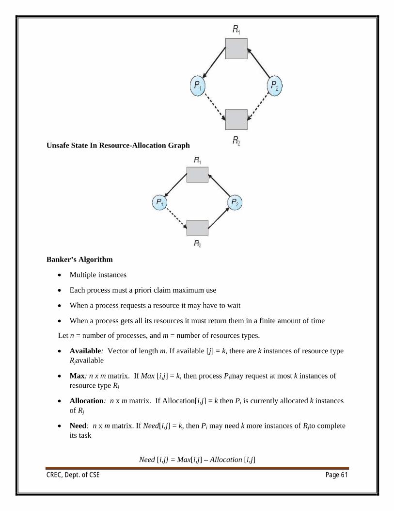
Banker’s Algorithm
∑ Multiple instances
∑ Each process must a priori claim maximum use
∑ When a process requests a resource it may have to wait
∑ When a process gets all its resources it must return them in a finite amount of time
Let n = number of processes, and m = number of resources types.
∑ Available: Vector of length m. If available [j] = k, there are k instances of resource type Rjavailable
∑ Max: n x m matrix. If Max [i,j] = k, then process Pimay request at most k instances of resource type Rj
∑ Allocation: n x m matrix. If Allocation[i,j] = k then Pi is currently allocated k instances of Rj
∑ Need: n x m matrix. If Need[i,j] = k, then Pi may need k more instances of Rjto complete its task
Need [i,j] = Max[i,j] – Allocation [i,j]
CREC, Dept. of CSE Page 62
Safety Algorithm
1. Let Work and Finish be vectors of length m and n, respectively. Initialize:
Work = Available
Finish [i] = false fori = 0, 1, …,n- 1
2. Find an isuch that both:
(a) Finish [i] = false
(b) Needi£Work
If no such iexists, go to step 4
3. Work = Work + Allocationi
Finish[i] = truego to step 2
4.IfFinish [i] == true for all i, then the system is in a safe state
Resource-Request Algorithm for Process Pi
Request = request vector for process Pi. If Requesti[j] = k then process Pi wants k instances of resource type Rj
1. If Requesti£Needigo to step 2. Otherwise, raise error condition, since process has exceeded its maximum claim
2. If Requesti£Available, go to step 3. Otherwise Pi must wait, since resources are not available
3. Pretend to allocate requested resources to Pi by modifying the state as follows:
Available = Available – Request;
Allocationi= Allocationi + Requesti;
Needi=Needi – Requesti;
o If safe the resources are allocated to Pi
o If unsafe Pi must wait, and the old resource-allocation state is restored
Example of Banker’s Algorithm
∑ 5 processes P0 through P4;
3 resource types:
A (10 instances), B (5instances), and C (7 instances)
Snapshot at time T0:
CREC, Dept. of CSE Page 63
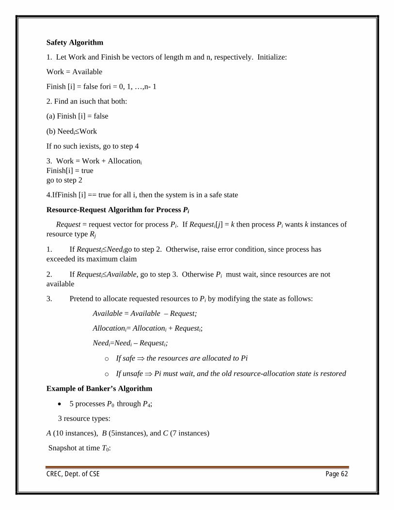
Allocation Max Available
A B C A B C A B C
P0 0 1 0 7 5 3 3 3 2
P1 2 0 0 3 2 2
P2 3 0 2 9 0 2
P3 2 1 1 2 2 2
P4 0 0 2 4 3 3
∑ The content of the matrix Need is defined to be Max – Allocation
Need
A B C
P0 7 4 3
P1 1 2 2
P2 6 0 0
P3 0 1 1
P4 4 3 1
∑ The system is in a safe state since the sequence <P1, P3, P4, P2, P0> satisfies safety criteria
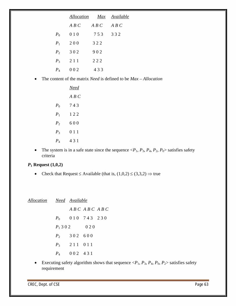
P1 Request (1,0,2)
∑ Check that Request £ Available (that is, (1,0,2) £ (3,3,2) true
Allocation Need Available
A B C A B C A B C
P0 0 1 0 7 4 3 2 3 0
P1 3 0 2 0 2 0
P2 3 0 2 6 0 0
P3 2 1 1 0 1 1
P4 0 0 2 4 3 1
∑ Executing safety algorithm shows that sequence <P1, P3, P4, P0, P2> satisfies safety requirement
CREC, Dept. of CSE Page 64
∑ Can request for (3,3,0) by P4 be granted?
∑ Can request for (0,2,0) by P0 be granted?
Deadlock Detection
∑ Allow system to enter deadlock state
∑ Detection algorithm
∑ Recovery scheme
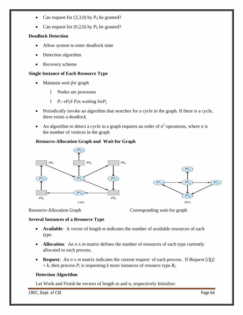
Single Instance of Each Resource Type
∑ Maintain wait-for graph
l Nodes are processes
l PiÆPjif Piis waiting forPj
∑ Periodically invoke an algorithm that searches for a cycle in the graph. If there is a cycle, there exists a deadlock
∑ An algorithm to detect a cycle in a graph requires an order of n2 operations, where n is the number of vertices in the graph
Resource-Allocation Graph and Wait-for Graph
Resource-Allocation Graph Corresponding wait-for graph
Several Instances of a Resource Type
∑ Available: A vector of length m indicates the number of available resources of each type.
∑ Allocation: An n x m matrix defines the number of resources of each type currently allocated to each process.
∑ Request: An n x m matrix indicates the current request of each process. If Request [i][j] = k, then process Pi is requesting k more instances of resource type.Rj.
Detection Algorithm
Let Work and Finish be vectors of length m and n, respectively Initialize:
CREC, Dept. of CSE Page 65
(a) Work = Available
(b) For i = 1,2, …, n, if Allocationiπ 0, then Finish[i] = false; otherwise, Finish[i] = true
2. Find an index isuch that both:
(a) Finish[i] == false
(b) Requesti£Work
If no such i exists, go to step 4
3. Work = Work + Allocationi
Finish[i] = truego to step 2
4. If Finish[i] == false, for some i, 1 £i£n, then the system is in deadlock state. Moreover, if Finish[i] == false, then Pi is deadlocked
Recovery from Deadlock:
Process Termination
∑ Abort all deadlocked processes
∑ Abort one process at a time until the deadlock cycle is eliminated
∑ In which order should we choose to abort?
o Priority of the process
o How long process has computed, and how much longer to completion
o Resources the process has used
o Resources process needs to complete
o How many processes will need to be terminated
o Is process interactive or batch?
Resource Preemption
∑ Selecting a victim – minimize cost
∑ Rollback – return to some safe state, restart process for that state
∑ Starvation – same process may always be picked as victim, include number of rollback in cost factor
CREC, Dept. of CSE Page 66
UNIT-4
Mass-Storage Systems, File-System Interface and Implementation
Overview of Mass Storage Structure
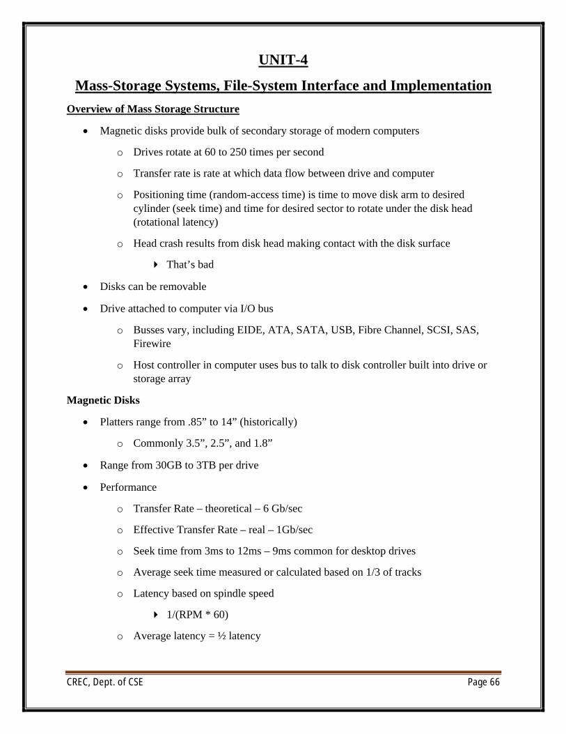
∑ Magnetic disks provide bulk of secondary storage of modern computers
o Drives rotate at 60 to 250 times per second
o Transfer rate is rate at which data flow between drive and computer
o Positioning time (random-access time) is time to move disk arm to desired cylinder (seek time) and time for desired sector to rotate under the disk head (rotational latency)
o Head crash results from disk head making contact with the disk surface
4 That’s bad
∑ Disks can be removable
∑ Drive attached to computer via I/O bus
o Busses vary, including EIDE, ATA, SATA, USB, Fibre Channel, SCSI, SAS, Firewire
o Host controller in computer uses bus to talk to disk controller built into drive or storage array
Magnetic Disks
∑ Platters range from .85” to 14” (historically)
o Commonly 3.5”, 2.5”, and 1.8”
∑ Range from 30GB to 3TB per drive
∑ Performance
o Transfer Rate – theoretical – 6 Gb/sec
o Effective Transfer Rate – real – 1Gb/sec
o Seek time from 3ms to 12ms – 9ms common for desktop drives
o Average seek time measured or calculated based on 1/3 of tracks
o Latency based on spindle speed
4 1/(RPM * 60)
o Average latency = ½ latency
CREC, Dept. of CSE Page 67
Magnetic Tape
∑ Was early secondary-storage medium
o Evolved from open spools to cartridges
∑ Relatively permanent and holds large quantities of data
∑ Access time slow
∑ Random access ~1000 times slower than disk
∑ Mainly used for backup, storage of infrequently-used data, transfer medium between systems
∑ Kept in spool and wound or rewound past read-write head
∑ Once data under head, transfer rates comparable to disk
o 140MB/sec and greater
∑ 200GB to 1.5TB typical storage
∑ Common technologies are LTO-{3,4,5} and T10000
Disk Structure
∑ Disk drives are addressed as large 1-dimensional arrays of logical blocks, where the logical block is the smallest unit of transfer
∑ The 1-dimensional array of logical blocks is mapped into the sectors of the disk sequentially
o Sector 0 is the first sector of the first track on the outermost cylinder
o Mapping proceeds in order through that track, then the rest of the tracks in that cylinder, and then through the rest of the cylinders from outermost to innermost
o Logical to physical address should be easy
CREC, Dept. of CSE Page 68
4 Except for bad sectors
4 Non-constant # of sectors per track via constant angular velocity
Disk Attachment
∑ Host-attached storage accessed through I/O ports talking to I/O busses
∑ SCSI itself is a bus, up to 16 devices on one cable, SCSI initiator requests operation and SCSI targets perform tasks
o Each target can have up to 8 logical units (disks attached to device controller)
o FC is high-speed serial architecture
o Can be switched fabric with 24-bit address space – the basis of storagearea networks (SANs) in which many hosts attach to many storage units
∑ I/O directed to bus ID, device ID, logical unit (LUN)
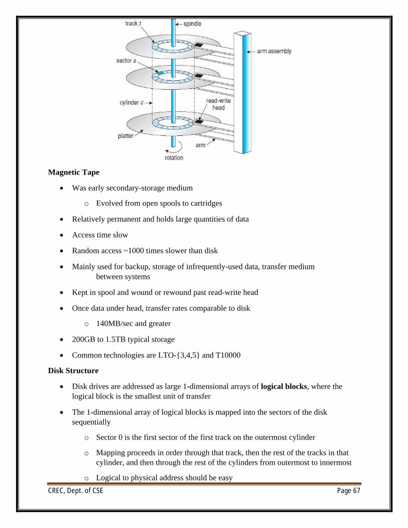
Storage Area Network
∑ Common in large storage environments
∑ Multiple hosts attached to multiple storage arrays – flexible
∑ SAN is one or more storage arrays
o Connected to one or more Fibre Channel switches
∑ Hosts also attach to the switches
∑ Storage made available via LUN Masking from specific arrays to specific servers
∑ Easy to add or remove storage, add new host and allocate it storage
o Over low-latency Fibre Channel fabric
o Why have separate storage networks and communications networks?
o Consider iSCSI, FCOE
CREC, Dept. of CSE Page 69
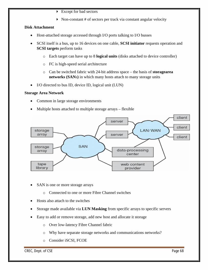
Network-Attached Storage
∑ Network-attached storage (NAS) is storage made available over a network rather than over a local connection (such as a bus)
o Remotely attaching to file systems
∑ NFS and CIFS are common protocols
∑ Implemented via remote procedure calls (RPCs) between host and storage over typically TCP or UDP on IP network
∑ iSCSI protocol uses IP network to carry the SCSI protocol
o Remotely attaching to devices (blocks)
Disk Scheduling
∑ The operating system is responsible for using hardware efficiently — for the disk drives, this means having a fast access time and disk bandwidth
∑ Minimize seek time
∑ Seek time ª seek distance
∑ Disk bandwidth is the total number of bytes transferred, divided by the total time between the first request for service and the completion of the last transfer
∑ There are many sources of disk I/O request
∑ OS
∑ System processes
∑ Users processes
∑ I/O request includes input or output mode, disk address, memory address, number of sectors to transfer
∑ OS maintains queue of requests, per disk or device
∑ Idle disk can immediately work on I/O request, busy disk means work must queue
CREC, Dept. of CSE Page 70
∑ Optimization algorithms only make sense when a queue exists
∑ Note that drive controllers have small buffers and can manage a queue of I/O requests (of varying “depth”)
∑ Several algorithms exist to schedule the servicing of disk I/O requests
∑ The analysis is true for one or many platters
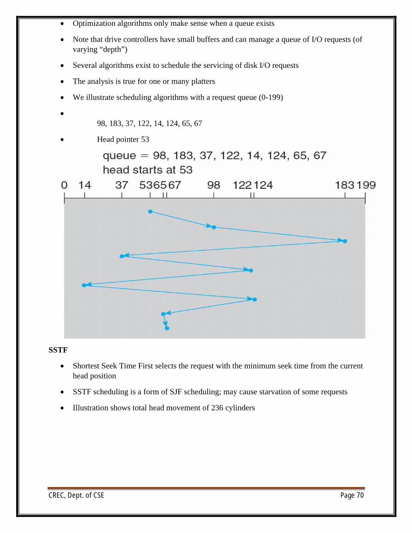
∑ We illustrate scheduling algorithms with a request queue (0-199)
∑98, 183, 37, 122, 14, 124, 65, 67
∑ Head pointer 53
SSTF
∑ Shortest Seek Time First selects the request with the minimum seek time from the current head position
∑ SSTF scheduling is a form of SJF scheduling; may cause starvation of some requests
∑ Illustration shows total head movement of 236 cylinders
CREC, Dept. of CSE Page 71
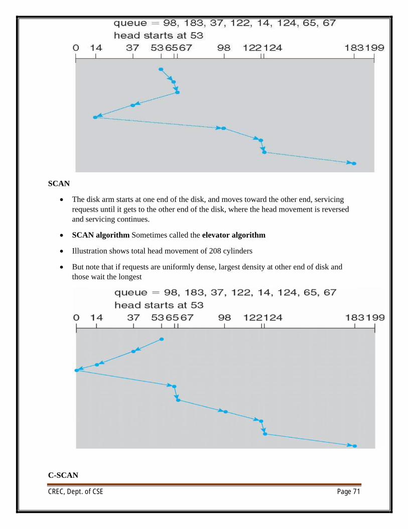
SCAN
∑ The disk arm starts at one end of the disk, and moves toward the other end, servicing requests until it gets to the other end of the disk, where the head movement is reversed and servicing continues.
∑ SCAN algorithm Sometimes called the elevator algorithm
∑ Illustration shows total head movement of 208 cylinders
∑ But note that if requests are uniformly dense, largest density at other end of disk and those wait the longest
C-SCAN
CREC, Dept. of CSE Page 72
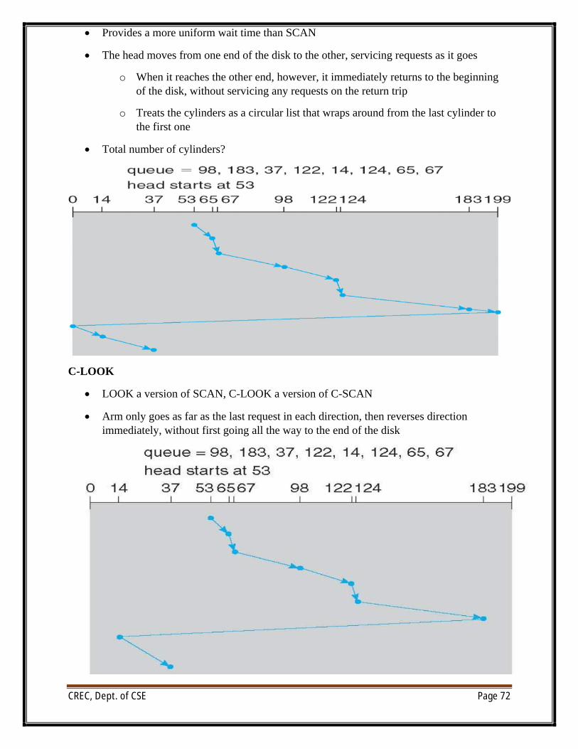
∑ Provides a more uniform wait time than SCAN
∑ The head moves from one end of the disk to the other, servicing requests as it goes
o When it reaches the other end, however, it immediately returns to the beginning of the disk, without servicing any requests on the return trip
o Treats the cylinders as a circular list that wraps around from the last cylinder to the first one
∑ Total number of cylinders?
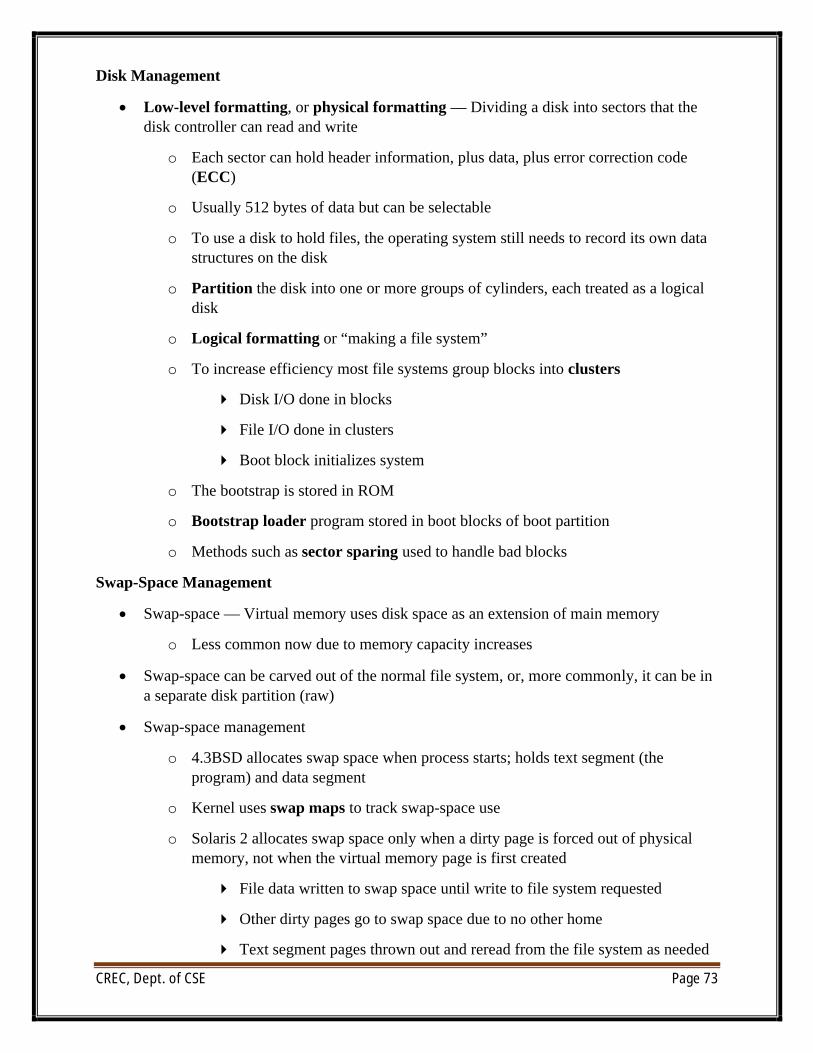
C-LOOK
∑ LOOK a version of SCAN, C-LOOK a version of C-SCAN
∑ Arm only goes as far as the last request in each direction, then reverses direction immediately, without first going all the way to the end of the disk
CREC, Dept. of CSE Page 73
Disk Management
∑ Low-level formatting, or physical formatting — Dividing a disk into sectors that thedisk controller can read and write
o Each sector can hold header information, plus data, plus error correction code (ECC)
o Usually 512 bytes of data but can be selectable
o To use a disk to hold files, the operating system still needs to record its own data structures on the disk
o Partition the disk into one or more groups of cylinders, each treated as a logical disk
o Logical formatting or “making a file system”
o To increase efficiency most file systems group blocks into clusters
4 Disk I/O done in blocks
4 File I/O done in clusters
4 Boot block initializes system
o The bootstrap is stored in ROM
o Bootstrap loader program stored in boot blocks of boot partition
o Methods such as sector sparing used to handle bad blocks
Swap-Space Management
∑ Swap-space — Virtual memory uses disk space as an extension of main memory
o Less common now due to memory capacity increases
∑ Swap-space can be carved out of the normal file system, or, more commonly, it can be in a separate disk partition (raw)
∑ Swap-space management
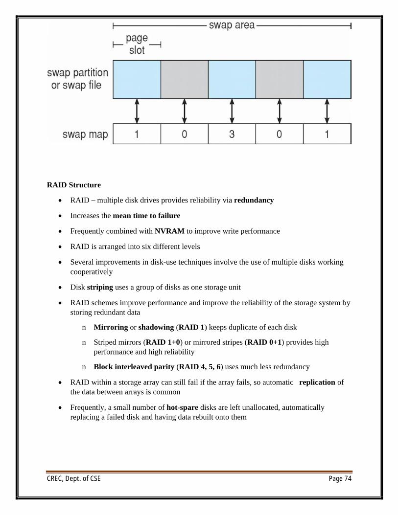
o 4.3BSD allocates swap space when process starts; holds text segment (the program) and data segment
o Kernel uses swap maps to track swap-space use
o Solaris 2 allocates swap space only when a dirty page is forced out of physical memory, not when the virtual memory page is first created
4 File data written to swap space until write to file system requested
4 Other dirty pages go to swap space due to no other home
4 Text segment pages thrown out and reread from the file system as needed
CREC, Dept. of CSE Page 74
RAID Structure
∑ RAID – multiple disk drives provides reliability via redundancy
∑ Increases the mean time to failure
∑ Frequently combined with NVRAM to improve write performance
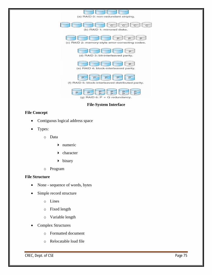
∑ RAID is arranged into six different levels
∑ Several improvements in disk-use techniques involve the use of multiple disks working cooperatively
∑ Disk striping uses a group of disks as one storage unit
∑ RAID schemes improve performance and improve the reliability of the storage system by storing redundant data
n Mirroring or shadowing (RAID 1) keeps duplicate of each disk
n Striped mirrors (RAID 1+0) or mirrored stripes (RAID 0+1) provides high performance and high reliability
n Block interleaved parity (RAID 4, 5, 6) uses much less redundancy
∑ RAID within a storage array can still fail if the array fails, so automatic replication of the data between arrays is common
∑ Frequently, a small number of hot-spare disks are left unallocated, automatically replacing a failed disk and having data rebuilt onto them
CREC, Dept. of CSE Page 75
File-System Interface
File Concept
∑ Contiguous logical address space
∑ Types:
o Data
4 numeric
4 character
4 binary
o Program
File Structure
∑ None - sequence of words, bytes
∑ Simple record structure
o Lines
o Fixed length
o Variable length
∑ Complex Structures
o Formatted document
o Relocatable load file
CREC, Dept. of CSE Page 76
∑ Can simulate last two with first method by inserting appropriate control characters
∑ Who decides:
o Operating system
o Program
File Attributes
∑ Name – only information kept in human-readable form
∑ Identifier – unique tag (number) identifies file within file system
∑ Type – needed for systems that support different types
∑ Location – pointer to file location on device
∑ Size – current file size
∑ Protection – controls who can do reading, writing, executing
∑ Time, date, and user identification – data for protection, security, and usage monitoring
∑ Information about files are kept in the directory structure, which is maintained on the disk
File Operations
∑ File is an abstract data type
∑ Create
∑ Write
∑ Read
∑ Reposition within file
∑ Delete
∑ Truncate
∑ Open(Fi) – search the directory structure on disk for entry Fi, and move the content of entry to memory
∑ Close (Fi) – move the content of entry Fi in memory to directory structure on disk
File Types – Name, Extension
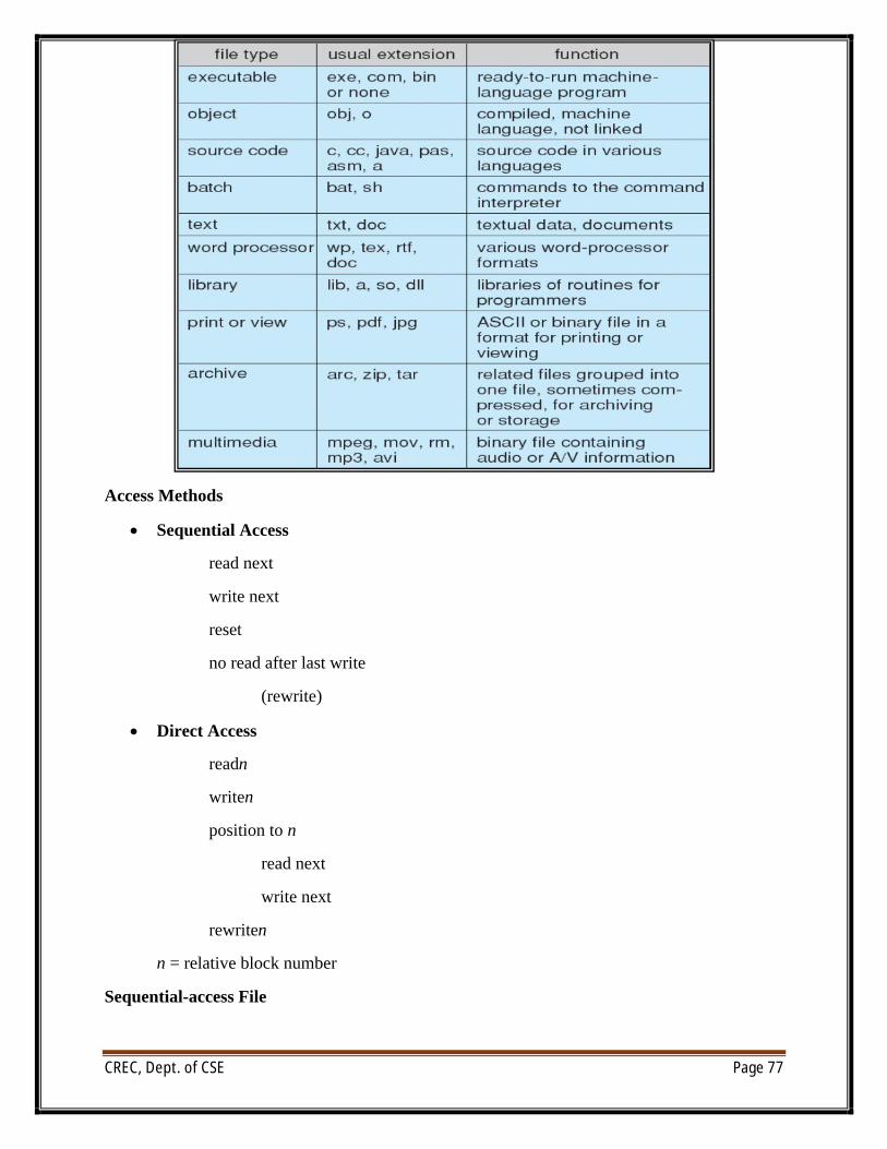
CREC, Dept. of CSE Page 77
Access Methods
∑ Sequential Access
read next
write next
reset
no read after last write
(rewrite)
∑ Direct Access
readn
writen
position to n
read next
write next
rewriten
n = relative block number
Sequential-access File
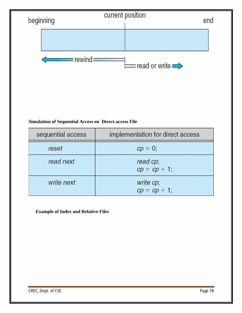
CREC, Dept. of CSE Page 78
Simulation of Sequential Access on Direct-access File
Example of Index and Relative Files
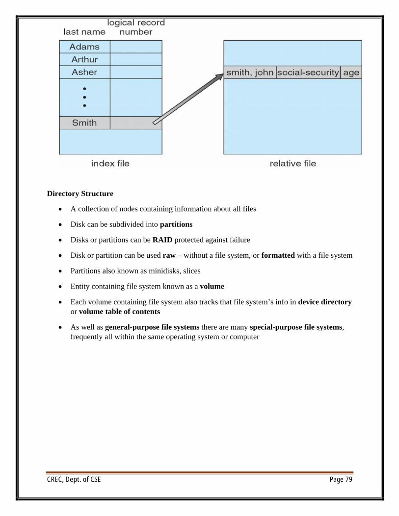
CREC, Dept. of CSE Page 79
Directory Structure
∑ A collection of nodes containing information about all files
∑ Disk can be subdivided into partitions
∑ Disks or partitions can be RAID protected against failure
∑ Disk or partition can be used raw – without a file system, or formatted with a file system
∑ Partitions also known as minidisks, slices
∑ Entity containing file system known as a volume
∑ Each volume containing file system also tracks that file system’s info in device directoryor volume table of contents
∑ As well as general-purpose file systems there are many special-purpose file systems, frequently all within the same operating system or computer
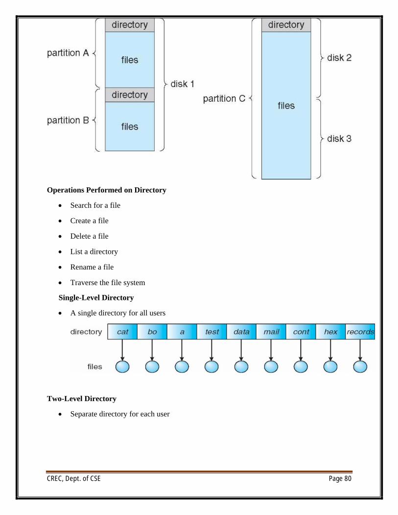
CREC, Dept. of CSE Page 80
Operations Performed on Directory
∑ Search for a file
∑ Create a file
∑ Delete a file
∑ List a directory
∑ Rename a file
∑ Traverse the file system
Single-Level Directory
∑ A single directory for all users
Two-Level Directory
∑ Separate directory for each user
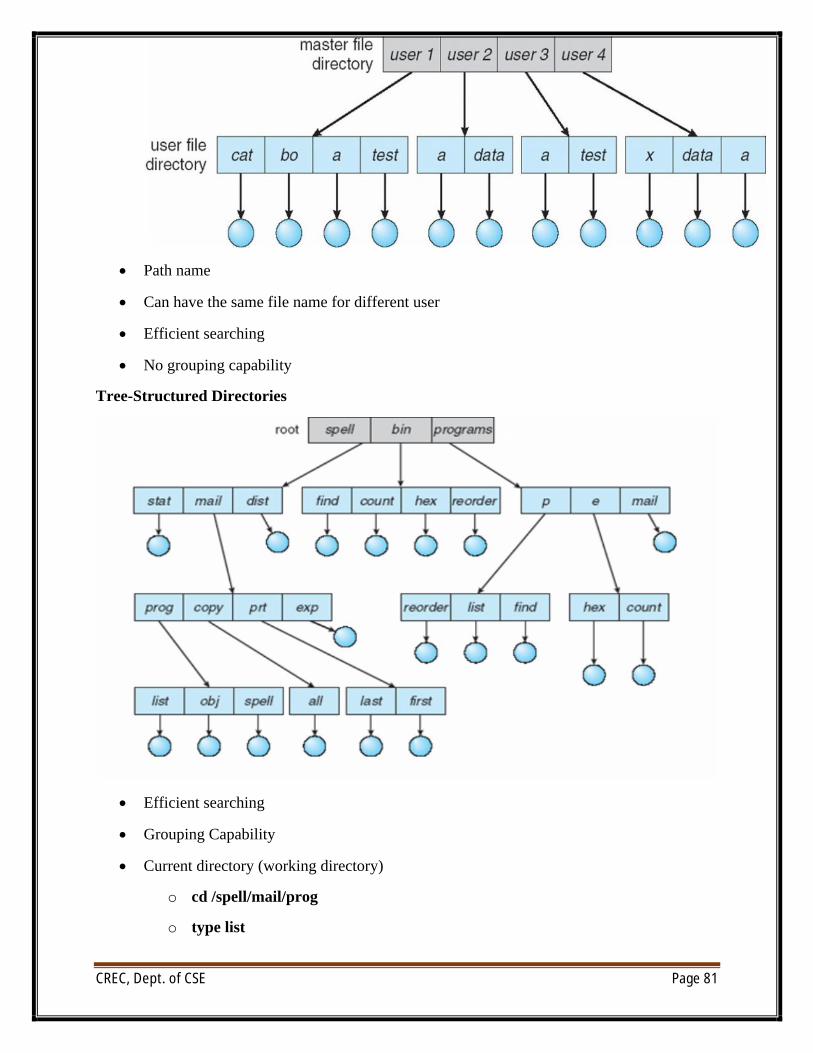
CREC, Dept. of CSE Page 81
∑ Path name
∑ Can have the same file name for different user
∑ Efficient searching
∑ No grouping capability
Tree-Structured Directories
∑ Efficient searching
∑ Grouping Capability
∑ Current directory (working directory)
o cd /spell/mail/prog
o type list
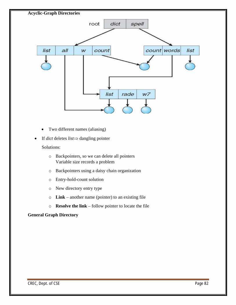
CREC, Dept. of CSE Page 82
Acyclic-Graph Directories
∑ Two different names (aliasing)
∑ If dict deletes list dangling pointer
Solutions:
o Backpointers, so we can delete all pointersVariable size records a problem
o Backpointers using a daisy chain organization
o Entry-hold-count solution
o New directory entry type
o Link – another name (pointer) to an existing file
o Resolve the link – follow pointer to locate the file
General Graph Directory
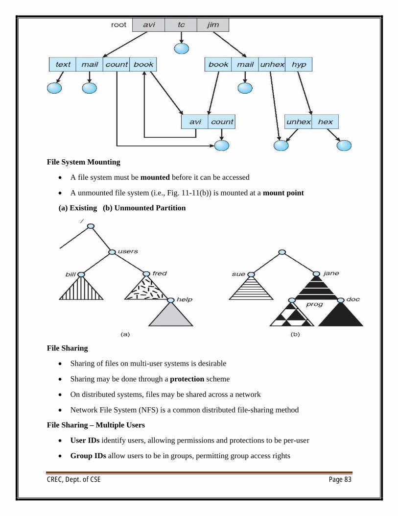
CREC, Dept. of CSE Page 83
File System Mounting
∑ A file system must be mounted before it can be accessed
∑ A unmounted file system (i.e., Fig. 11-11(b)) is mounted at a mount point
(a) Existing (b) Unmounted Partition
File Sharing
∑ Sharing of files on multi-user systems is desirable
∑ Sharing may be done through a protection scheme
∑ On distributed systems, files may be shared across a network
∑ Network File System (NFS) is a common distributed file-sharing method
File Sharing – Multiple Users
∑ User IDs identify users, allowing permissions and protections to be per-user
∑ Group IDs allow users to be in groups, permitting group access rights
CREC, Dept. of CSE Page 84
Remote File Systems
∑ Uses networking to allow file system access between systems
o Manually via programs like FTP
o Automatically, seamlessly using distributed file systems
o Semi automatically via the world wide web
∑ Client-server model allows clients to mount remote file systems from servers
o Server can serve multiple clients
o Client and user-on-client identification is insecure or complicated
o NFS is standard UNIX client-server file sharing protocol
o CIFS is standard Windows protocol
o Standard operating system file calls are translated into remote calls
∑ Distributed Information Systems (distributed naming services) such as LDAP, DNS, NIS, Active Directory implement unified access to information needed for remote computing
Failure Modes
∑ Remote file systems add new failure modes, due to network failure, server failure
∑ Recovery from failure can involve state information about status of each remote request
∑ Stateless protocols such as NFS include all information in each request, allowing easy recovery but less security
Consistency Semantics
Consistency semantics specify how multiple users are to access a shared file simultaneously
∑ Similar to Ch 7 process synchronization algorithms
4 Tend to be less complex due to disk I/O and network latency (for remote file systems
∑ Andrew File System (AFS) implemented complex remote file sharing semantics
∑ Unix file system (UFS) implements:
4 Writes to an open file visible immediately to other users of the same open file
4 Sharing file pointer to allow multiple users to read and write concurrently
∑ AFS has session semantics
4 Writes only visible to sessions starting after the file is closed
File System Implementation\
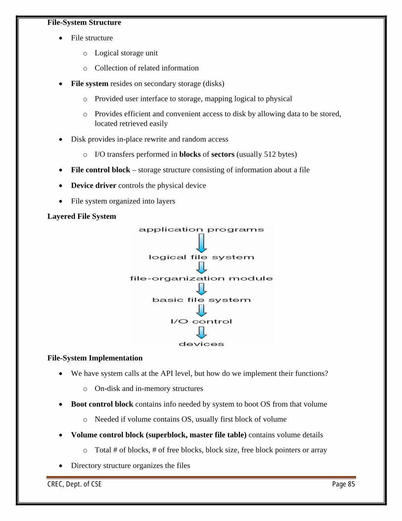
CREC, Dept. of CSE Page 85
File-System Structure
∑ File structure
o Logical storage unit
o Collection of related information
∑ File system resides on secondary storage (disks)
o Provided user interface to storage, mapping logical to physical
o Provides efficient and convenient access to disk by allowing data to be stored, located retrieved easily
∑ Disk provides in-place rewrite and random access
o I/O transfers performed in blocks of sectors (usually 512 bytes)
∑ File control block – storage structure consisting of information about a file
∑ Device driver controls the physical device
∑ File system organized into layers
Layered File System
File-System Implementation
∑ We have system calls at the API level, but how do we implement their functions?
o On-disk and in-memory structures
∑ Boot control block contains info needed by system to boot OS from that volume
o Needed if volume contains OS, usually first block of volume
∑ Volume control block (superblock, master file table) contains volume details
o Total # of blocks, # of free blocks, block size, free block pointers or array
∑ Directory structure organizes the files
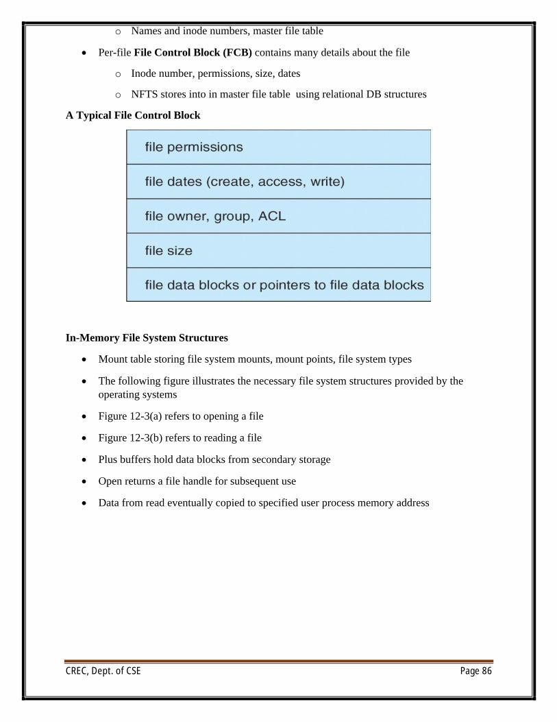
CREC, Dept. of CSE Page 86
o Names and inode numbers, master file table
∑ Per-file File Control Block (FCB) contains many details about the file
o Inode number, permissions, size, dates
o NFTS stores into in master file table using relational DB structures
A Typical File Control Block
In-Memory File System Structures
∑ Mount table storing file system mounts, mount points, file system types
∑ The following figure illustrates the necessary file system structures provided by the operating systems
∑ Figure 12-3(a) refers to opening a file
∑ Figure 12-3(b) refers to reading a file
∑ Plus buffers hold data blocks from secondary storage
∑ Open returns a file handle for subsequent use
∑ Data from read eventually copied to specified user process memory address
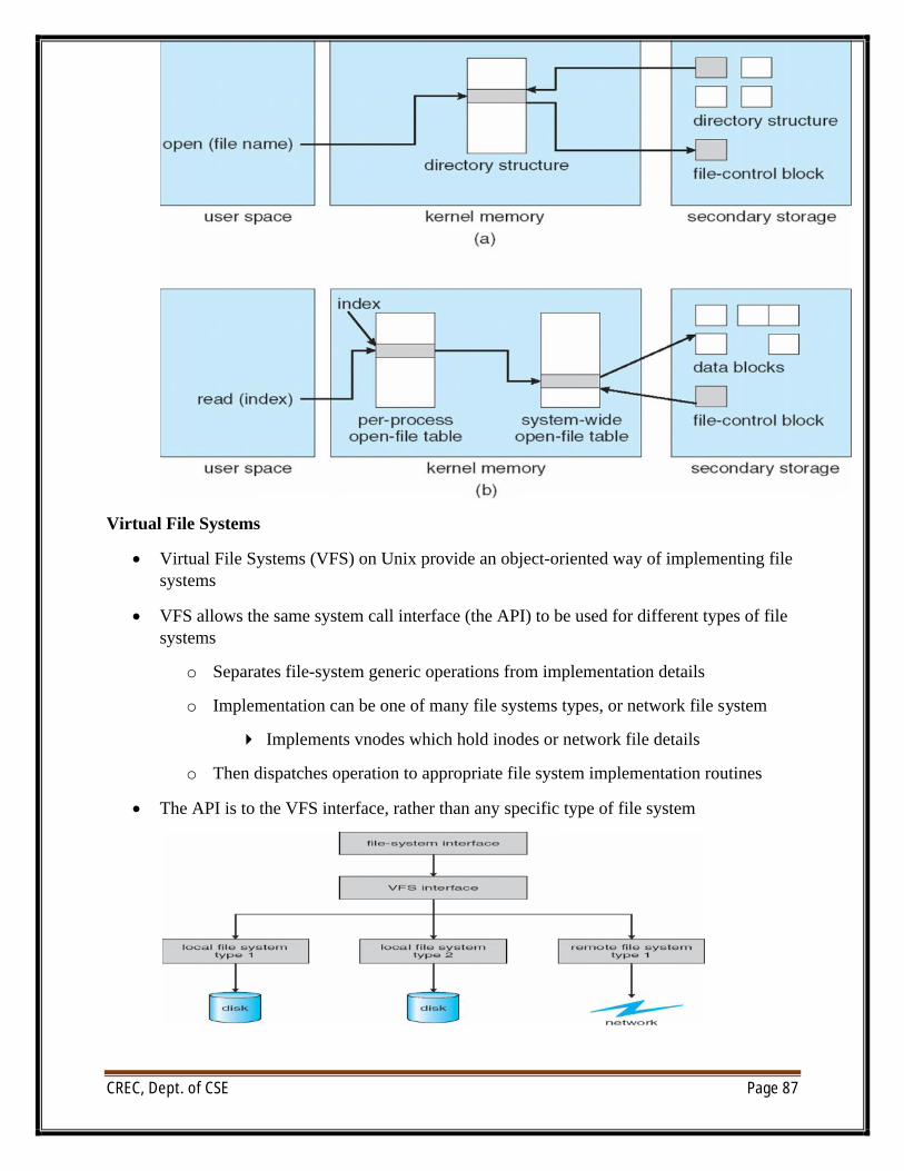
CREC, Dept. of CSE Page 87
Virtual File Systems
∑ Virtual File Systems (VFS) on Unix provide an object-oriented way of implementing file systems
∑ VFS allows the same system call interface (the API) to be used for different types of file systems
o Separates file-system generic operations from implementation details
o Implementation can be one of many file systems types, or network file system
4 Implements vnodes which hold inodes or network file details
o Then dispatches operation to appropriate file system implementation routines
∑ The API is to the VFS interface, rather than any specific type of file system
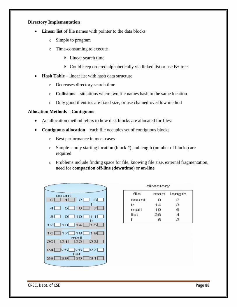
CREC, Dept. of CSE Page 88
Directory Implementation
∑ Linear list of file names with pointer to the data blocks
o Simple to program
o Time-consuming to execute
4 Linear search time
4 Could keep ordered alphabetically via linked list or use B+ tree
∑ Hash Table – linear list with hash data structure
o Decreases directory search time
o Collisions – situations where two file names hash to the same location
o Only good if entries are fixed size, or use chained-overflow method
Allocation Methods – Contiguous
∑ An allocation method refers to how disk blocks are allocated for files:
∑ Contiguous allocation – each file occupies set of contiguous blocks
o Best performance in most cases
o Simple – only starting location (block #) and length (number of blocks) are required
o Problems include finding space for file, knowing file size, external fragmentation, need for compaction off-line (downtime) or on-line
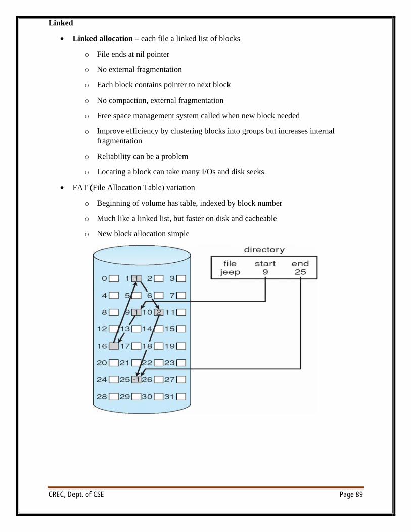
CREC, Dept. of CSE Page 89
Linked
∑ Linked allocation – each file a linked list of blocks
o File ends at nil pointer
o No external fragmentation
o Each block contains pointer to next block
o No compaction, external fragmentation
o Free space management system called when new block needed
o Improve efficiency by clustering blocks into groups but increases internal fragmentation
o Reliability can be a problem
o Locating a block can take many I/Os and disk seeks
∑ FAT (File Allocation Table) variation
o Beginning of volume has table, indexed by block number
o Much like a linked list, but faster on disk and cacheable
o New block allocation simple
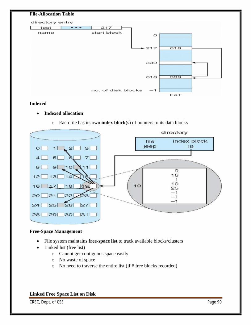
CREC, Dept. of CSE Page 90
File-Allocation Table
Indexed
∑ Indexed allocation
o Each file has its own index block(s) of pointers to its data blocks
Free-Space Management
∑ File system maintains free-space list to track available blocks/clusters∑ Linked list (free list)
o Cannot get contiguous space easilyo No waste of spaceo No need to traverse the entire list (if # free blocks recorded)
Linked Free Space List on Disk
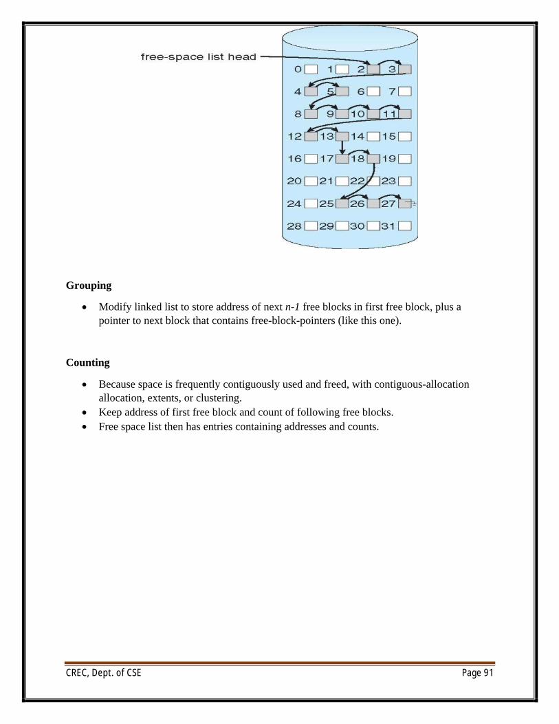
CREC, Dept. of CSE Page 91
Grouping
∑ Modify linked list to store address of next n-1 free blocks in first free block, plus a pointer to next block that contains free-block-pointers (like this one).
Counting
∑ Because space is frequently contiguously used and freed, with contiguous-allocation allocation, extents, or clustering.
∑ Keep address of first free block and count of following free blocks.∑ Free space list then has entries containing addresses and counts.
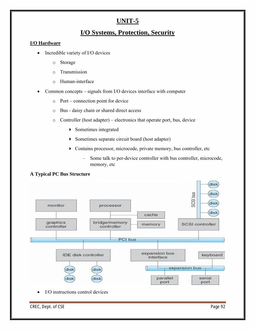
CREC, Dept. of CSE Page 92
UNIT-5
I/O Systems, Protection, Security
I/O Hardware
∑ Incredible variety of I/O devices
o Storage
o Transmission
o Human-interface
∑ Common concepts – signals from I/O devices interface with computer
o Port – connection point for device
o Bus - daisy chain or shared direct access
o Controller (host adapter) – electronics that operate port, bus, device
4 Sometimes integrated
4 Sometimes separate circuit board (host adapter)
4 Contains processor, microcode, private memory, bus controller, etc
– Some talk to per-device controller with bus controller, microcode, memory, etc
A Typical PC Bus Structure
∑ I/O instructions control devices
CREC, Dept. of CSE Page 93
∑ Devices usually have registers where device driver places commands, addresses, and data to write, or read data from registers after command execution
l Data-in register, data-out register, status register, control register
l Typically 1-4 bytes, or FIFO buffer
∑ Devices have addresses, used by
l Direct I/O instructions
l Memory-mapped I/O
4 Device data and command registers mapped to processor address space
4 Especially for large address spaces (graphics)
Polling
∑ For each byte of I/O
1. Read busy bit from status register until 0
2. Host sets read or write bit and if write copies data into data-out register
3. Host sets command-ready bit
4. Controller sets busy bit, executes transfer
5. Controller clears busy bit, error bit, command-ready bit when transfer done
6. Step 1 is busy-wait cycle to wait for I/O from device
7. Reasonable if device is fast
8. But inefficient if device slow
9. CPU switches to other tasks?
4 But if miss a cycle data overwritten / lost
Interrupts
∑ Polling can happen in 3 instruction cycles
o Read status, logical-and to extract status bit, branch if not zero
o How to be more efficient if non-zero infrequently?
∑ CPU Interrupt-request line triggered by I/O device
o Checked by processor after each instruction
∑ Interrupt handler receives interrupts
o Maskable to ignore or delay some interrupts
∑ Interrupt vector to dispatch interrupt to correct handler
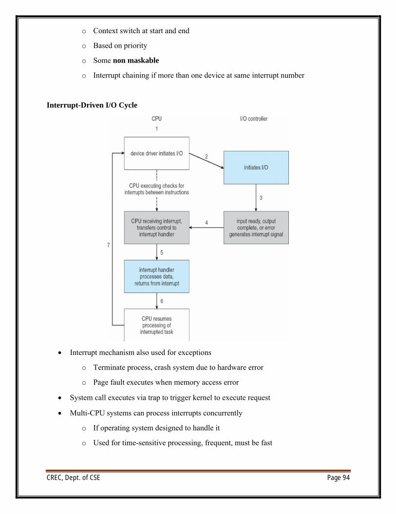
CREC, Dept. of CSE Page 94
o Context switch at start and end
o Based on priority
o Some non maskable
o Interrupt chaining if more than one device at same interrupt number
Interrupt-Driven I/O Cycle
∑ Interrupt mechanism also used for exceptions
o Terminate process, crash system due to hardware error
o Page fault executes when memory access error
∑ System call executes via trap to trigger kernel to execute request
∑ Multi-CPU systems can process interrupts concurrently
o If operating system designed to handle it
o Used for time-sensitive processing, frequent, must be fast
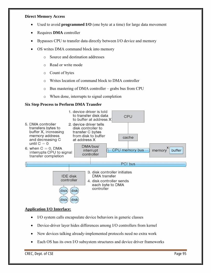
CREC, Dept. of CSE Page 95
Direct Memory Access
∑ Used to avoid programmed I/O (one byte at a time) for large data movement
∑ Requires DMA controller
∑ Bypasses CPU to transfer data directly between I/O device and memory
∑ OS writes DMA command block into memory
o Source and destination addresses
o Read or write mode
o Count of bytes
o Writes location of command block to DMA controller
o Bus mastering of DMA controller – grabs bus from CPU
o When done, interrupts to signal completion
Six Step Process to Perform DMA Transfer
Application I/O Interface:
∑ I/O system calls encapsulate device behaviors in generic classes
∑ Device-driver layer hides differences among I/O controllers from kernel
∑ New devices talking already-implemented protocols need no extra work
∑ Each OS has its own I/O subsystem structures and device driver frameworks
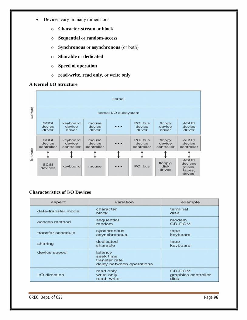
CREC, Dept. of CSE Page 96
∑ Devices vary in many dimensions
o Character-stream or block
o Sequential or random-access
o Synchronous or asynchronous (or both)
o Sharable or dedicated
o Speed of operation
o read-write, read only, or write only
A Kernel I/O Structure
Characteristics of I/O Devices
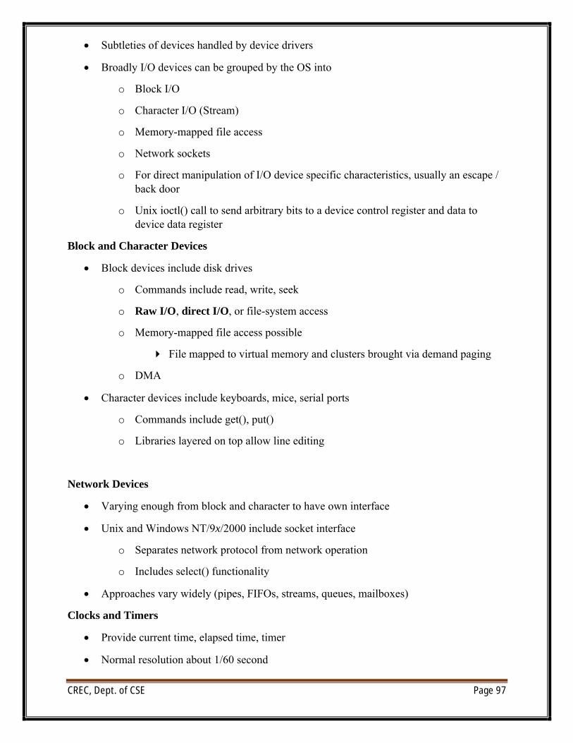
CREC, Dept. of CSE Page 97
∑ Subtleties of devices handled by device drivers
∑ Broadly I/O devices can be grouped by the OS into
o Block I/O
o Character I/O (Stream)
o Memory-mapped file access
o Network sockets
o For direct manipulation of I/O device specific characteristics, usually an escape / back door
o Unix ioctl() call to send arbitrary bits to a device control register and data to device data register
Block and Character Devices
∑ Block devices include disk drives
o Commands include read, write, seek
o Raw I/O, direct I/O, or file-system access
o Memory-mapped file access possible
4 File mapped to virtual memory and clusters brought via demand paging
o DMA
∑ Character devices include keyboards, mice, serial ports
o Commands include get(), put()
o Libraries layered on top allow line editing
Network Devices
∑ Varying enough from block and character to have own interface
∑ Unix and Windows NT/9x/2000 include socket interface
o Separates network protocol from network operation
o Includes select() functionality
∑ Approaches vary widely (pipes, FIFOs, streams, queues, mailboxes)
Clocks and Timers
∑ Provide current time, elapsed time, timer
∑ Normal resolution about 1/60 second
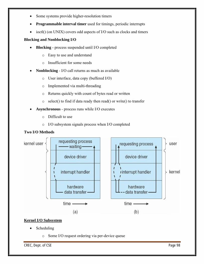
CREC, Dept. of CSE Page 98
∑ Some systems provide higher-resolution timers
∑ Programmable interval timer used for timings, periodic interrupts
∑ ioctl() (on UNIX) covers odd aspects of I/O such as clocks and timers
Blocking and Nonblocking I/O
∑ Blocking - process suspended until I/O completed
o Easy to use and understand
o Insufficient for some needs
∑ Nonblocking - I/O call returns as much as available
o User interface, data copy (buffered I/O)
o Implemented via multi-threading
o Returns quickly with count of bytes read or written
o select() to find if data ready then read() or write() to transfer
∑ Asynchronous - process runs while I/O executes
o Difficult to use
o I/O subsystem signals process when I/O completed
Two I/O Methods
Kernel I/O Subsystem
∑ Scheduling
o Some I/O request ordering via per-device queue
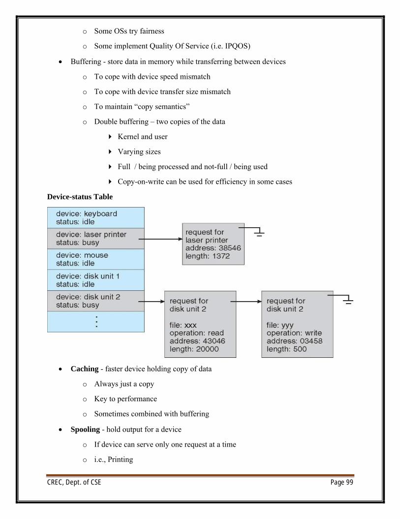
CREC, Dept. of CSE Page 99
o Some OSs try fairness
o Some implement Quality Of Service (i.e. IPQOS)
∑ Buffering - store data in memory while transferring between devices
o To cope with device speed mismatch
o To cope with device transfer size mismatch
o To maintain “copy semantics”
o Double buffering – two copies of the data
4 Kernel and user
4 Varying sizes
4 Full / being processed and not-full / being used
4 Copy-on-write can be used for efficiency in some cases
Device-status Table
∑ Caching - faster device holding copy of data
o Always just a copy
o Key to performance
o Sometimes combined with buffering
∑ Spooling - hold output for a device
o If device can serve only one request at a time
o i.e., Printing
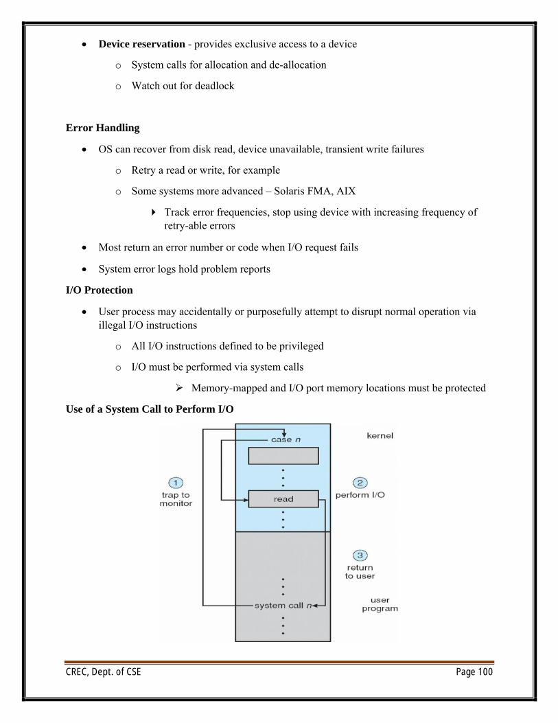
CREC, Dept. of CSE Page 100
∑ Device reservation - provides exclusive access to a device
o System calls for allocation and de-allocation
o Watch out for deadlock
Error Handling
∑ OS can recover from disk read, device unavailable, transient write failures
o Retry a read or write, for example
o Some systems more advanced – Solaris FMA, AIX
4 Track error frequencies, stop using device with increasing frequency of retry-able errors
∑ Most return an error number or code when I/O request fails
∑ System error logs hold problem reports
I/O Protection
∑ User process may accidentally or purposefully attempt to disrupt normal operation via illegal I/O instructions
o All I/O instructions defined to be privileged
o I/O must be performed via system calls
ÿ Memory-mapped and I/O port memory locations must be protected
Use of a System Call to Perform I/O
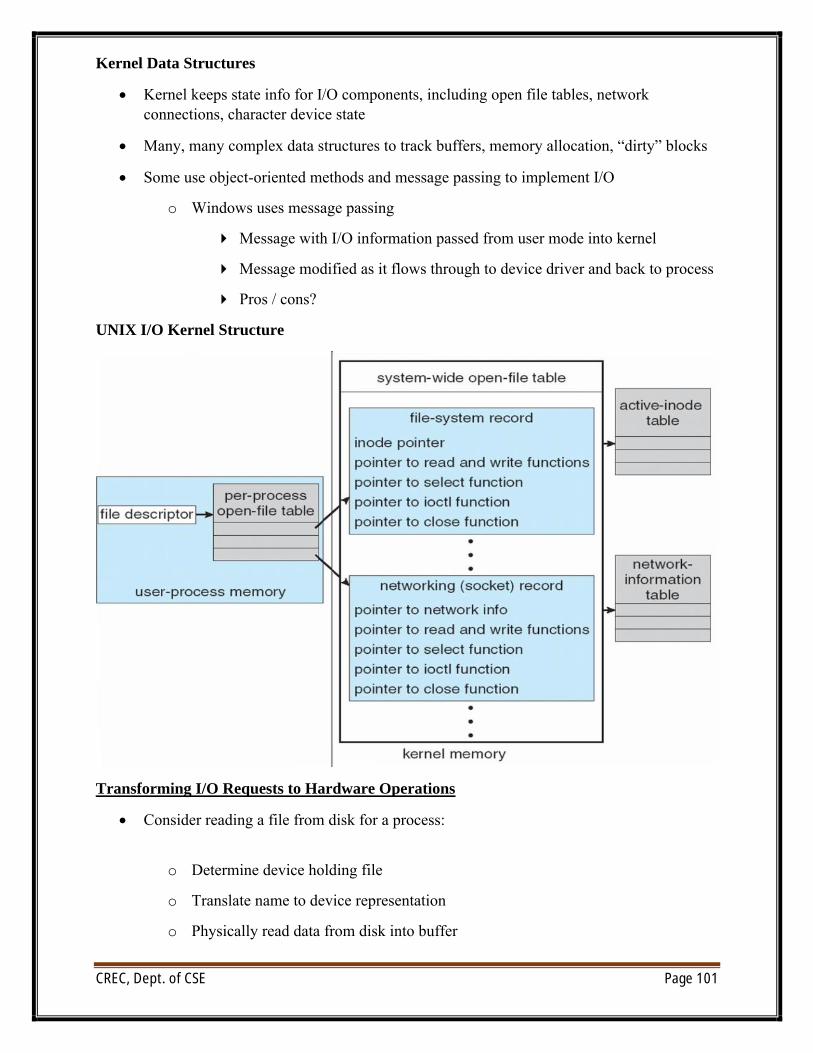
CREC, Dept. of CSE Page 101
Kernel Data Structures
∑ Kernel keeps state info for I/O components, including open file tables, network connections, character device state
∑ Many, many complex data structures to track buffers, memory allocation, “dirty” blocks
∑ Some use object-oriented methods and message passing to implement I/O
o Windows uses message passing
4 Message with I/O information passed from user mode into kernel
4 Message modified as it flows through to device driver and back to process
4 Pros / cons?
UNIX I/O Kernel Structure
Transforming I/O Requests to Hardware Operations
∑ Consider reading a file from disk for a process:
o Determine device holding file
o Translate name to device representation
o Physically read data from disk into buffer
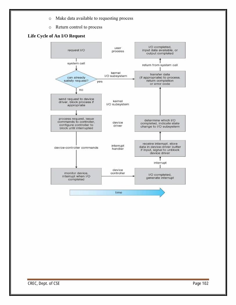
CREC, Dept. of CSE Page 102
o Make data available to requesting process
o Return control to process
Life Cycle of An I/O Request
CREC, Dept. of CSE Page 103
Protection
Goals of Protection:
∑ In one protection model, computer consists of a collection of objects, hardware or software
∑ Each object has a unique name and can be accessed through a well-defined set of operations
∑ Protection problem - ensure that each object is accessed correctly and only by those processes that are allowed to do so
Principles of Protection
∑ Guiding principle – principle of least privilege
o Programs, users and systems should be given just enough privileges to perform their tasks
o Limits damage if entity has a bug, gets abused
o Can be static (during life of system, during life of process)
o Or dynamic (changed by process as needed) – domain switching, privilege escalation
o “Need to know” a similar concept regarding access to data
∑ Must consider “grain” aspect
o Rough-grained privilege management easier, simpler, but least privilege now done in large chunks
o For example, traditional Unix processes either have abilities of the associated user, or of root
o Fine-grained management more complex, more overhead, but more protective
o File ACL lists, RBAC
o Domain can be user, process, procedure
Domain Structure
∑ Access-right = <object-name, rights-set>where rights-set is a subset of all valid operations that can be performed on the object
∑ Domain = set of access-rights
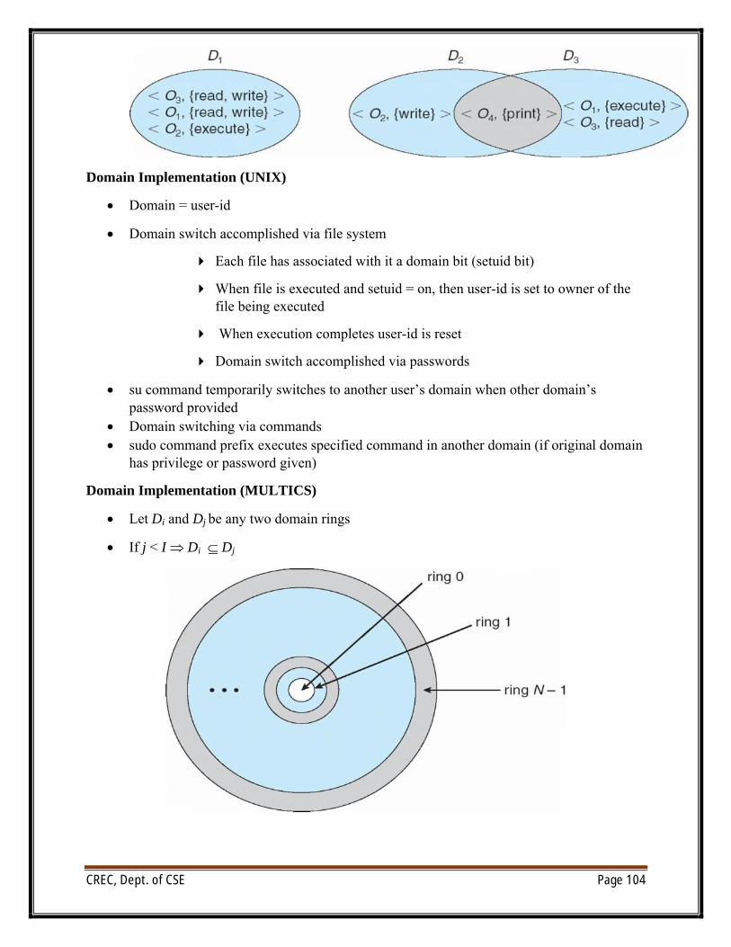
CREC, Dept. of CSE Page 104
Domain Implementation (UNIX)
∑ Domain = user-id
∑ Domain switch accomplished via file system
4 Each file has associated with it a domain bit (setuid bit)
4 When file is executed and setuid = on, then user-id is set to owner of the file being executed
4 When execution completes user-id is reset
4 Domain switch accomplished via passwords
∑ su command temporarily switches to another user’s domain when other domain’s password provided
∑ Domain switching via commands∑ sudo command prefix executes specified command in another domain (if original domain
has privilege or password given)
Domain Implementation (MULTICS)
∑ Let Di and Dj be any two domain rings
∑ If j < I Di Õ Dj
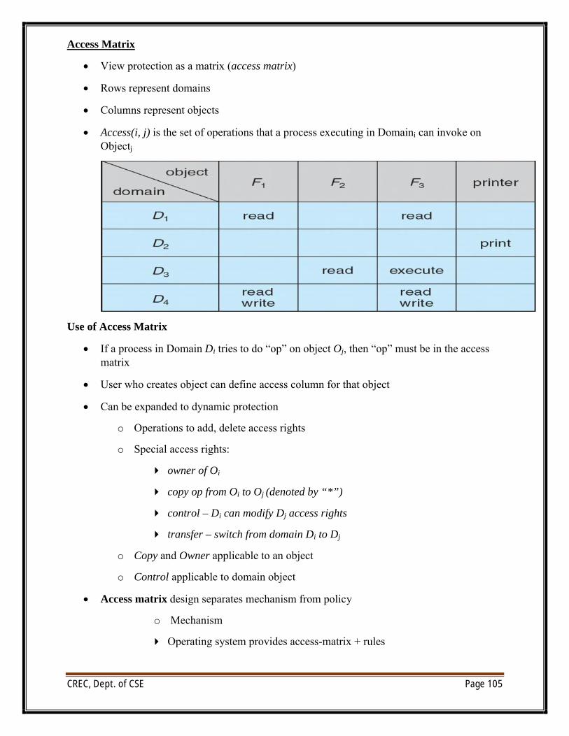
CREC, Dept. of CSE Page 105
Access Matrix
∑ View protection as a matrix (access matrix)
∑ Rows represent domains
∑ Columns represent objects
∑ Access(i, j) is the set of operations that a process executing in Domaini can invoke on Objectj
Use of Access Matrix
∑ If a process in Domain Di tries to do “op” on object Oj, then “op” must be in the access matrix
∑ User who creates object can define access column for that object
∑ Can be expanded to dynamic protection
o Operations to add, delete access rights
o Special access rights:
4 owner of Oi
4 copy op from Oi to Oj (denoted by “*”)
4 control – Di can modify Dj access rights
4 transfer – switch from domain Di to Dj
o Copy and Owner applicable to an object
o Control applicable to domain object
∑ Access matrix design separates mechanism from policy
o Mechanism
4 Operating system provides access-matrix + rules
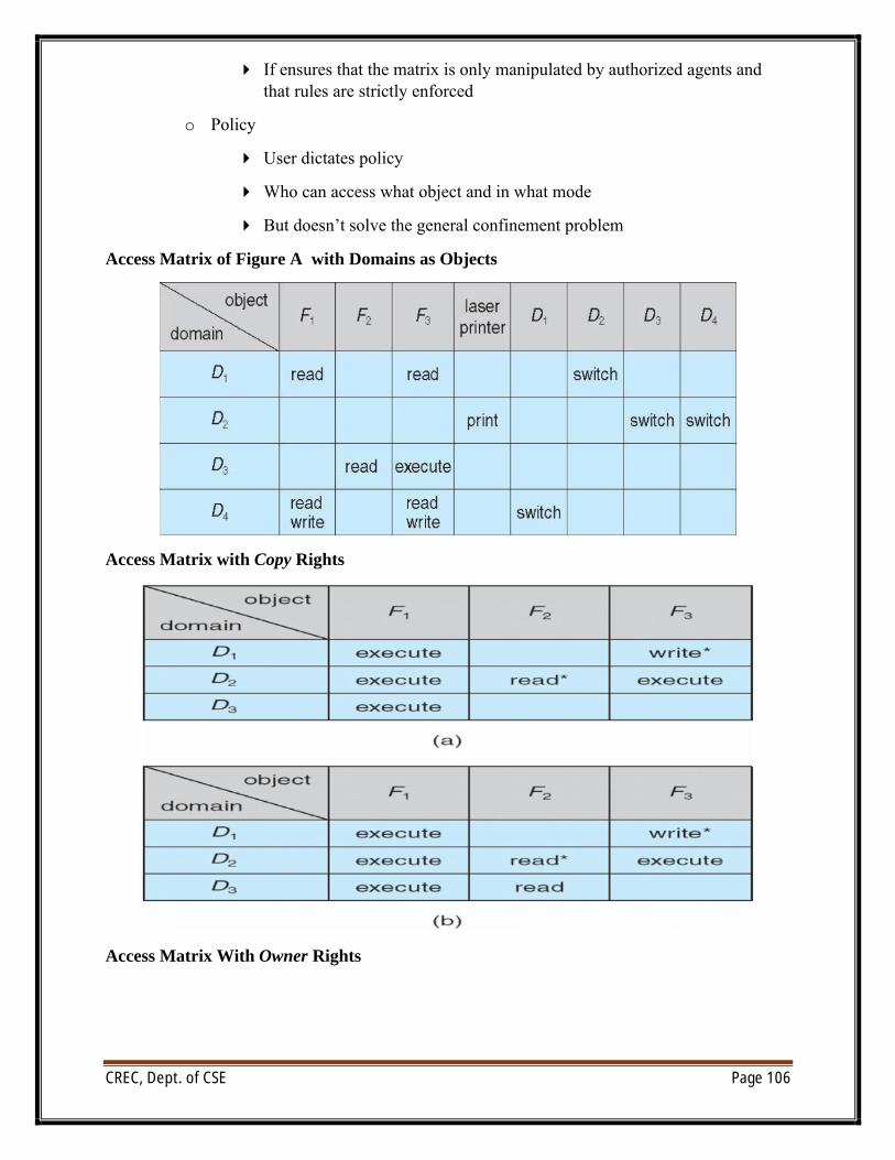
CREC, Dept. of CSE Page 106
4 If ensures that the matrix is only manipulated by authorized agents and that rules are strictly enforced
o Policy
4 User dictates policy
4 Who can access what object and in what mode
4 But doesn’t solve the general confinement problem
Access Matrix of Figure A with Domains as Objects
Access Matrix with Copy Rights
Access Matrix With Owner Rights
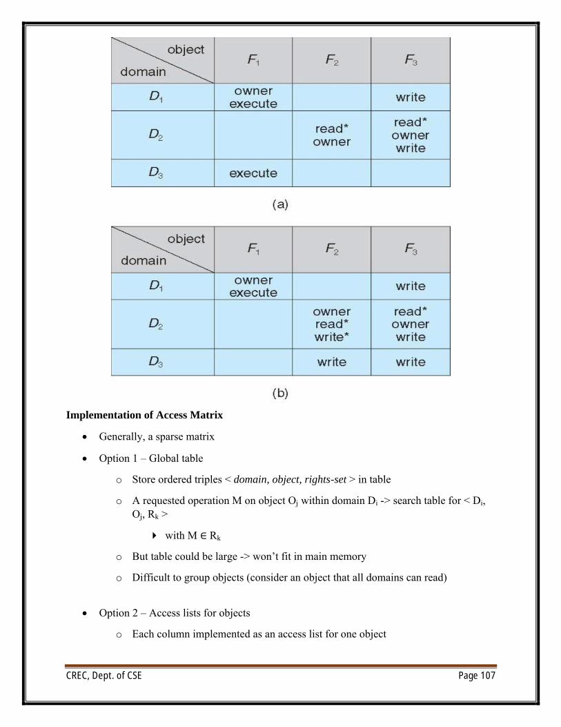
CREC, Dept. of CSE Page 107
Implementation of Access Matrix
∑ Generally, a sparse matrix
∑ Option 1 – Global table
o Store ordered triples < domain, object, rights-set > in table
o A requested operation M on object Oj within domain Di -> search table for < Di, Oj, Rk >
4 with M ∈ Rk
o But table could be large -> won’t fit in main memory
o Difficult to group objects (consider an object that all domains can read)
∑ Option 2 – Access lists for objects
o Each column implemented as an access list for one object
CREC, Dept. of CSE Page 108
o Resulting per-object list consists of ordered pairs < domain, rights-set > defining all domains with non-empty set of access rights for the object
o Easily extended to contain default set -> If M ∈ default set, also allow access
∑ Each column = Access-control list for one object Defines who can perform what operation
Domain 1 = Read, WriteDomain 2 = ReadDomain 3 = Read
∑ Each Row = Capability List (like a key)For each domain, what operations allowed on what objects
Object F1 – Read
Object F4 – Read, Write, Execute
Object F5 – Read, Write, Delete, Copy
∑ Option 3 – Capability list for domains
o Instead of object-based, list is domain based
o Capability list for domain is list of objects together with operations allows on them
o Object represented by its name or address, called a capability
o Execute operation M on object Oj, process requests operation and specifies capability as parameter
4 Possession of capability means access is allowed
o Capability list associated with domain but never directly accessible by domain
4 Rather, protected object, maintained by OS and accessed indirectly
4 Like a “secure pointer”
4 Idea can be extended up to applications
∑ Option 4 – Lock-key
o Compromise between access lists and capability lists
o Each object has list of unique bit patterns, called locks
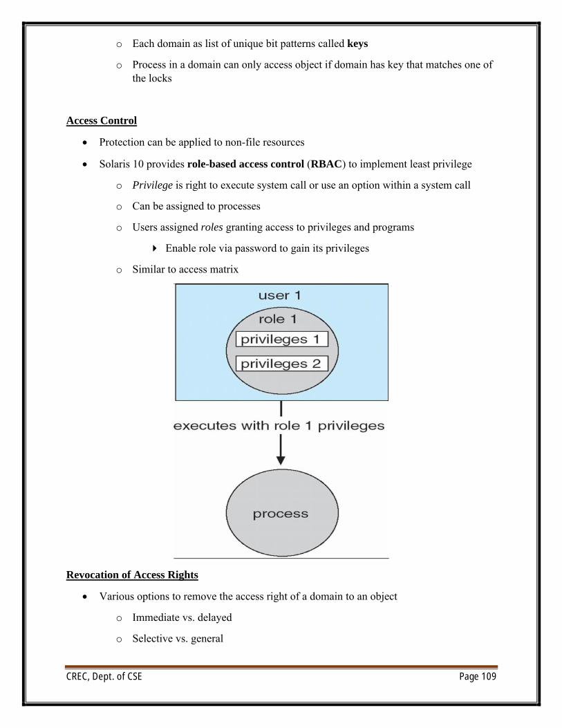
CREC, Dept. of CSE Page 109
o Each domain as list of unique bit patterns called keys
o Process in a domain can only access object if domain has key that matches one of the locks
Access Control
∑ Protection can be applied to non-file resources
∑ Solaris 10 provides role-based access control (RBAC) to implement least privilege
o Privilege is right to execute system call or use an option within a system call
o Can be assigned to processes
o Users assigned roles granting access to privileges and programs
4 Enable role via password to gain its privileges
o Similar to access matrix
Revocation of Access Rights
∑ Various options to remove the access right of a domain to an object
o Immediate vs. delayed
o Selective vs. general
CREC, Dept. of CSE Page 110
o Partial vs. total
o Temporary vs. permanent
∑ Access List – Delete access rights from access list
o Simple – search access list and remove entry
o Immediate, general or selective, total or partial, permanent or temporary
∑ Capability List – Scheme required to locate capability in the system before capability can be revoked
o Reacquisition – periodic delete, with require and denial if revoked
o Back-pointers – set of pointers from each object to all capabilities of that object (Multics)
o Indirection – capability points to global table entry which points to object – delete entry from global table, not selective (CAL)
o Keys – unique bits associated with capability, generated when capability created
4 Master key associated with object, key matches master key for access
4 Revocation – create new master key
4 Policy decision of who can create and modify keys – object owner or others?
Capability-Based Systems
∑ Hydra
o Fixed set of access rights known to and interpreted by the system
4 i.e. read, write, or execute each memory segment
4 User can declare other auxiliary rights and register those with protection system
4 Accessing process must hold capability and know name of operation
4 Rights amplification allowed by trustworthy procedures for a specific type
o Interpretation of user-defined rights performed solely by user's program; system provides access protection for use of these rights
o Operations on objects defined procedurally – procedures are objects accessed indirectly by capabilities
o Solves the problem of mutually suspicious subsystems
o Includes library of prewritten security routines
CREC, Dept. of CSE Page 111
∑ Cambridge CAP System
o Simpler but powerful
o Data capability - provides standard read, write, execute of individual storage segments associated with object – implemented in microcode
o Software capability -interpretation left to the subsystem, through its protected procedures
4 Only has access to its own subsystem
4 Programmers must learn principles and techniques of protection
Language-Based Protection
∑ Specification of protection in a programming language allows the high-level description of policies for the allocation and use of resources
∑ Language implementation can provide software for protection enforcement when automatic hardware-supported checking is unavailable
∑ Interpret protection specifications to generate calls on whatever protection system is provided by the hardware and the operating system
Security
The Security Problem:
∑ System secure if resources used and accessed as intended under all circumstances
l Unachievable
∑ Intruders (crackers) attempt to breach security
∑ Threat is potential security violation
∑ Attack is attempt to breach security
∑ Attack can be accidental or malicious
∑ Easier to protect against accidental than malicious misuse
Security Violation Categories
∑ Breach of confidentiality
o Unauthorized reading of data
∑ Breach of integrity
o Unauthorized modification of data
∑ Breach of availability
o Unauthorized destruction of data
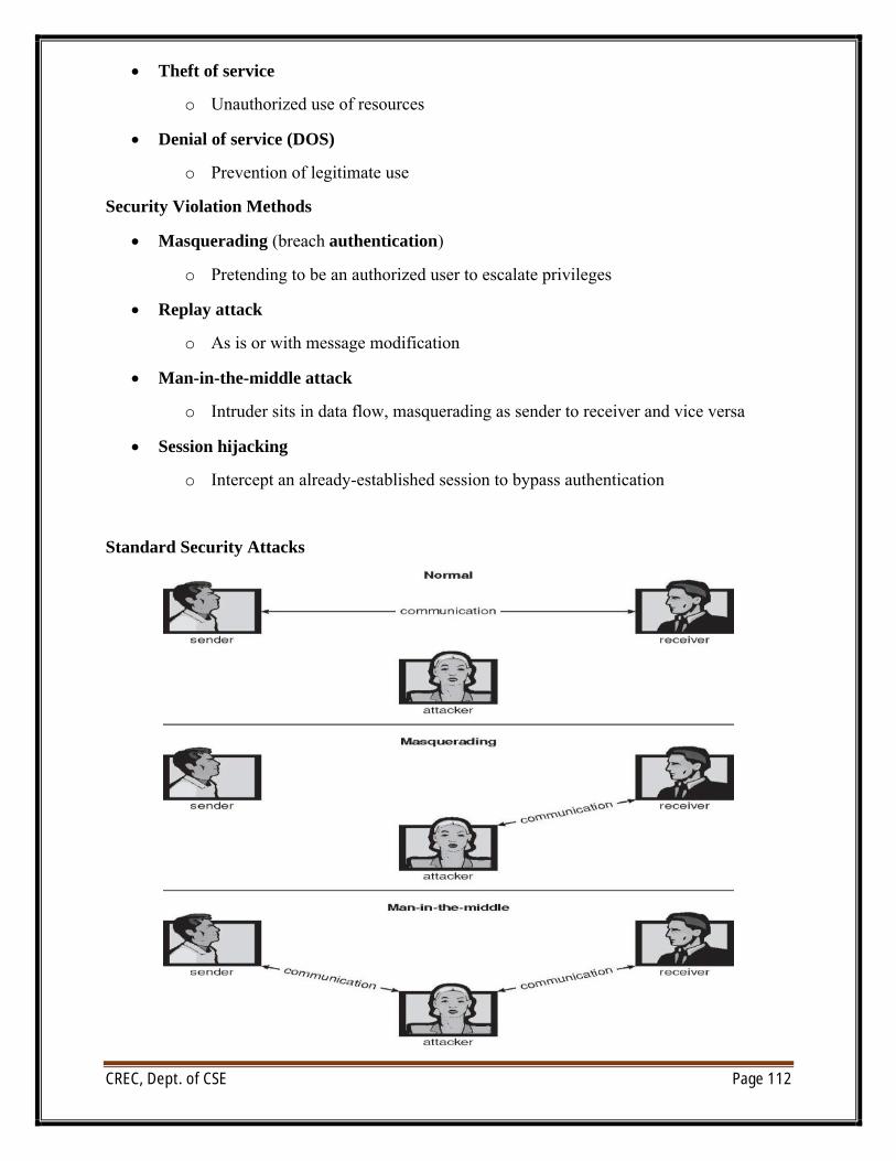
CREC, Dept. of CSE Page 112
∑ Theft of service
o Unauthorized use of resources
∑ Denial of service (DOS)
o Prevention of legitimate use
Security Violation Methods
∑ Masquerading (breach authentication)
o Pretending to be an authorized user to escalate privileges
∑ Replay attack
o As is or with message modification
∑ Man-in-the-middle attack
o Intruder sits in data flow, masquerading as sender to receiver and vice versa
∑ Session hijacking
o Intercept an already-established session to bypass authentication
Standard Security Attacks
CREC, Dept. of CSE Page 113
Security Measure Levels
∑ Security must occur at four levels to be effective:
o Physical
4 Data centers, servers, connected terminals
o Human
4 Avoid social engineering, phishing, dumpster diving
o Operating System
4 Protection mechanisms, debugging
o Network
4 Intercepted communications, interruption, DOS
∑ Security is as weak as the weakest link in the chain
Program Threats
∑ Many variations, many names
∑ Trojan Horse
o Code segment that misuses its environment
o Exploits mechanisms for allowing programs written by users to be executed by other users
o Spyware, pop-up browser windows, covert channels
o Up to 80% of spam delivered by spyware-infected systems
∑ Trap Door
o Specific user identifier or password that circumvents normal security procedures
o Could be included in a compiler
∑ Logic Bomb
o Program that initiates a security incident under certain circumstances
∑ Stack and Buffer Overflow
o Exploits a bug in a program (overflow either the stack or memory buffers)
o Failure to check bounds on inputs, arguments
o Write past arguments on the stack into the return address on stack
o When routine returns from call, returns to hacked address
n Pointed to code loaded onto stack that executes malicious code
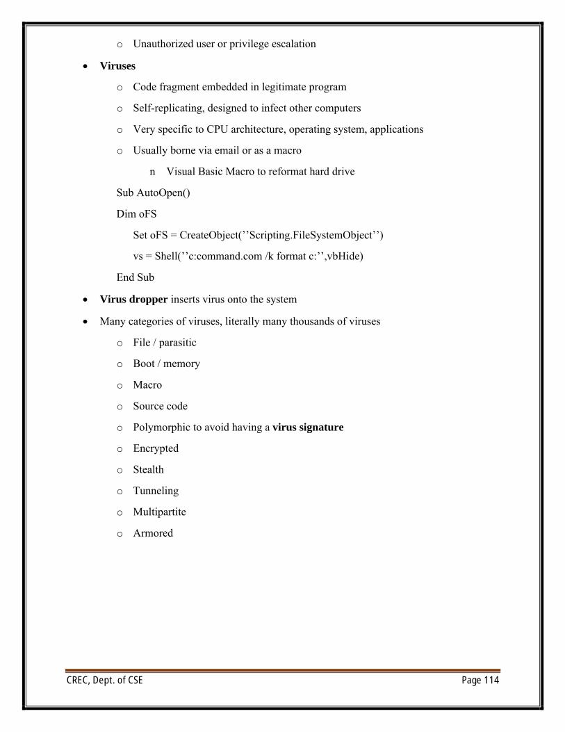
CREC, Dept. of CSE Page 114
o Unauthorized user or privilege escalation
∑ Viruses
o Code fragment embedded in legitimate program
o Self-replicating, designed to infect other computers
o Very specific to CPU architecture, operating system, applications
o Usually borne via email or as a macro
n Visual Basic Macro to reformat hard drive
Sub AutoOpen()
Dim oFS
Set oFS = CreateObject(’’Scripting.FileSystemObject’’)
vs = Shell(’’c:command.com /k format c:’’,vbHide)
End Sub
∑ Virus dropper inserts virus onto the system
∑ Many categories of viruses, literally many thousands of viruses
o File / parasitic
o Boot / memory
o Macro
o Source code
o Polymorphic to avoid having a virus signature
o Encrypted
o Stealth
o Tunneling
o Multipartite
o Armored
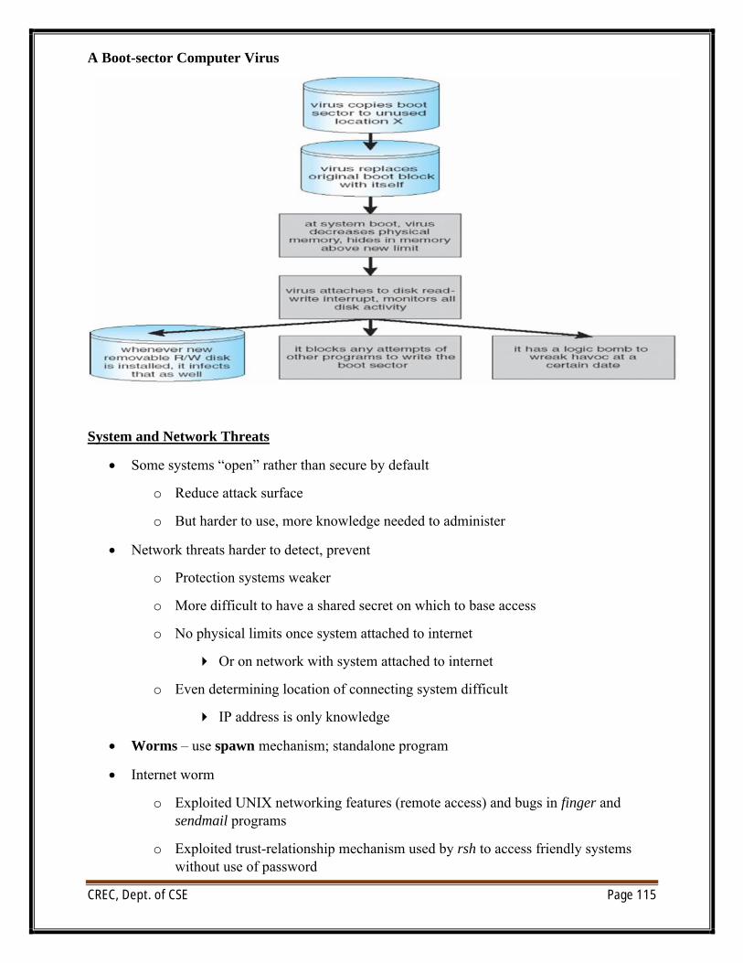
CREC, Dept. of CSE Page 115
A Boot-sector Computer Virus
System and Network Threats
∑ Some systems “open” rather than secure by default
o Reduce attack surface
o But harder to use, more knowledge needed to administer
∑ Network threats harder to detect, prevent
o Protection systems weaker
o More difficult to have a shared secret on which to base access
o No physical limits once system attached to internet
4 Or on network with system attached to internet
o Even determining location of connecting system difficult
4 IP address is only knowledge
∑ Worms – use spawn mechanism; standalone program
∑ Internet worm
o Exploited UNIX networking features (remote access) and bugs in finger and sendmail programs
o Exploited trust-relationship mechanism used by rsh to access friendly systems without use of password
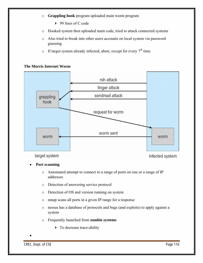
CREC, Dept. of CSE Page 116
o Grappling hook program uploaded main worm program
4 99 lines of C code
o Hooked system then uploaded main code, tried to attack connected systems
o Also tried to break into other users accounts on local system via password guessing
o If target system already infected, abort, except for every 7th time
The Morris Internet Worm
∑ Port scanning
o Automated attempt to connect to a range of ports on one or a range of IP addresses
o Detection of answering service protocol
o Detection of OS and version running on system
o nmap scans all ports in a given IP range for a response
o nessus has a database of protocols and bugs (and exploits) to apply against a system
o Frequently launched from zombie systems
4 To decrease trace-ability
∑
CREC, Dept. of CSE Page 117
∑ Denial of Service
o Overload the targeted computer preventing it from doing any useful work
o Distributed denial-of-service (DDOS) come from multiple sites at once
o Consider the start of the IP-connection handshake (SYN)
4 How many started-connections can the OS handle?
o Consider traffic to a web site
o Accidental – CS students writing bad fork() code
o Purposeful – extortion, punishment
Cryptography as a Security Tool
∑ Broadest security tool available
o Internal to a given computer, source and destination of messages can be known and protected
4 OS creates, manages, protects process IDs, communication ports
o Source and destination of messages on network cannot be trusted without cryptography
4 Local network – IP address?
– Consider unauthorized host added
4 WAN / Internet – how to establish authenticity
– Not via IP address
Cryptography
∑ Means to constrain potential senders (sources) and / or receivers (destinations) of messages
o Based on secrets (keys)
o Enables
4 Confirmation of source
4 Receipt only by certain destination
4 Trust relationship between sender and receiver
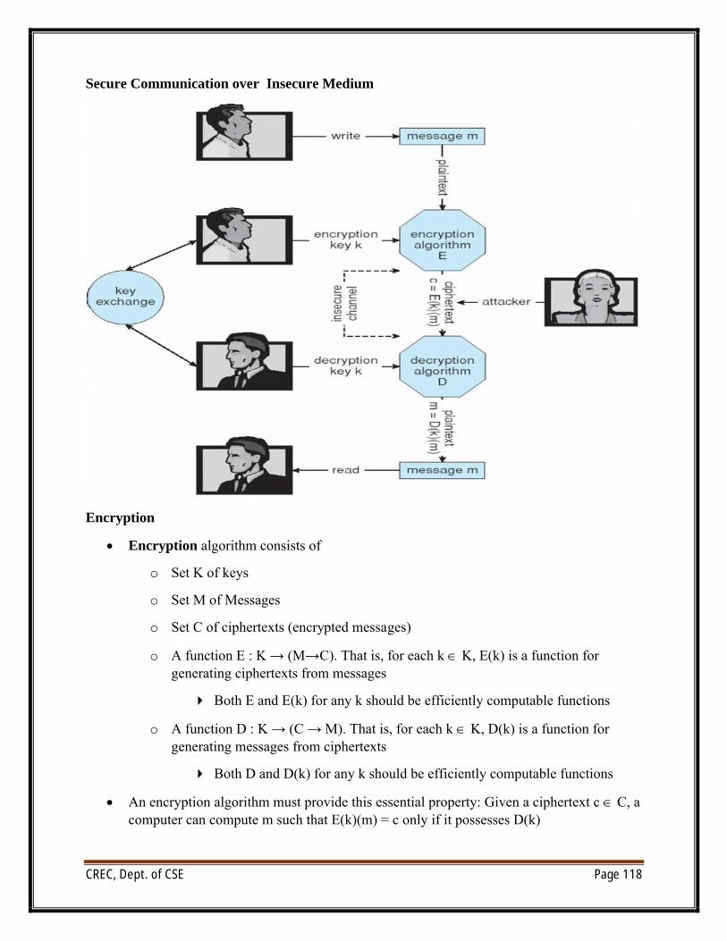
CREC, Dept. of CSE Page 118
Secure Communication over Insecure Medium
Encryption
∑ Encryption algorithm consists of
o Set K of keys
o Set M of Messages
o Set C of ciphertexts (encrypted messages)
o A function E : K → (M→C). That is, for each k Œ K, E(k) is a function for generating ciphertexts from messages
4 Both E and E(k) for any k should be efficiently computable functions
o A function D : K → (C → M). That is, for each k Œ K, D(k) is a function for generating messages from ciphertexts
4 Both D and D(k) for any k should be efficiently computable functions
∑ An encryption algorithm must provide this essential property: Given a ciphertext c Œ C, a computer can compute m such that E(k)(m) = c only if it possesses D(k)
CREC, Dept. of CSE Page 119
o Thus, a computer holding D(k) can decrypt ciphertexts to the plaintexts used to produce them, but a computer not holding D(k) cannot decrypt ciphertexts
o Since ciphertexts are generally exposed (for example, sent on the network), it is important that it be infeasible to derive D(k) from the ciphertexts
Symmetric Encryption
∑ Same key used to encrypt and decrypt
o E(k) can be derived from D(k), and vice versa
o DES is most commonly used symmetric block-encryption algorithm (created by US Govt)
o Encrypts a block of data at a time
o Triple-DES considered more secure
∑ Advanced Encryption Standard (AES), twofish up and coming
∑ RC4 is most common symmetric stream cipher, but known to have vulnerabilities
o Encrypts/decrypts a stream of bytes (i.e., wireless transmission)
o Key is a input to psuedo-random-bit generator
4 Generates an infinite keystream
Asymmetric Encryption
∑ Public-key encryption based on each user having two keys:
o public key – published key used to encrypt data
o private key – key known only to individual user used to decrypt data
∑ Must be an encryption scheme that can be made public without making it easy to figure out the decryption scheme
o Most common is RSA block cipher
o Efficient algorithm for testing whether or not a number is prime
o No efficient algorithm is know for finding the prime factors of a number
∑ Formally, it is computationally infeasible to derive D(kd , N) from E(ke , N), and so E(ke , N) need not be kept secret and can be widely disseminated
o E(ke , N) (or just ke) is the public key
o D(kd , N) (or just kd) is the private key
o N is the product of two large, randomly chosen prime numbers p and q (for example, p and q are 512 bits each)
CREC, Dept. of CSE Page 120
o Encryption algorithm is E(ke , N)(m) = mke mod N, where ke satisfies kekd mod (p−1)(q −1) = 1
o The decryption algorithm is then D(kd , N)(c) = ckd mod N
Asymmetric Encryption Example
∑ For example. make p = 7and q = 13
∑ We then calculate N = 7∗13 = 91 and (p−1)(q−1) = 72
∑ We next select ke relatively prime to 72 and< 72, yielding 5
∑ Finally,we calculate kd such that kekd mod 72 = 1, yielding 29
∑ We how have our keys
o Public key, ke, N = 5, 91
o Private key, kd , N = 29, 91
o Encrypting the message 69 with the public key results in the cyphertext 62
∑ Cyphertext can be decoded with the private key
o Public key can be distributed in cleartext to anyone who wants to communicate with holder of public key
Authentication
∑ Constraining set of potential senders of a message
o Complementary and sometimes redundant to encryption
o Also can prove message unmodified
∑ Algorithm components
o A set K of keys
o A set M of messages
o A set A of authenticators
o A function S : K → (M→ A)
4 That is, for each k ΠK, S(k) is a function for generating authenticators from messages
4 Both S and S(k) for any k should be efficiently computable functions
o A function V : K → (M× A→ {true, false}). That is, for each k Œ K, V(k) is a function for verifying authenticators on messages
4 Both V and V(k) for any k should be efficiently computable functions
CREC, Dept. of CSE Page 121
∑ For a message m, a computer can generate an authenticator a Œ A such that V(k)(m, a) = true only if it possesses S(k)
∑ Thus, computer holding S(k) can generate authenticators on messages so that any other computer possessing V(k) can verify them
∑ Computer not holding S(k) cannot generate authenticators on messages that can be verified using V(k)
∑ Since authenticators are generally exposed (for example, they are sent on the network with the messages themselves), it must not be feasible to derive S(k) from the authenticators
Authentication – Hash Functions
∑ Basis of authentication
∑ Creates small, fixed-size block of data (message digest, hash value) from m
∑ Hash Function H must be collision resistant on m
o Must be infeasible to find an m’ ≠ m such that H(m) = H(m’)
o If H(m) = H(m’), then m = m’
o The message has not been modified
o Common message-digest functions include MD5, which produces a 128-bit hash, and SHA-1, which outputs a 160-bit hash
Authentication – MAC
∑ Symmetric encryption used in message-authentication code (MAC) authentication algorithm
∑ Simple example:
o MAC defines S(k)(m) = f (k, H(m))
4 Where f is a function that is one-way on its first argument
– k cannot be derived from f (k, H(m))
4 Because of the collision resistance in the hash function, reasonably assured no other message could create the same MAC
4 A suitable verification algorithm is V(k)(m, a) ≡ ( f (k,m) = a)
4 Note that k is needed to compute both S(k) and V(k), so anyone able to compute one can compute the other
Authentication – Digital Signature
∑ Based on asymmetric keys and digital signature algorithm
CREC, Dept. of CSE Page 122
∑ Authenticators produced are digital signatures
∑ In a digital-signature algorithm, computationally infeasible to derive S(ks ) from V(kv)
o V is a one-way function
o Thus, kv is the public key and ks is the private key
∑ Consider the RSA digital-signature algorithm
o Similar to the RSA encryption algorithm, but the key use is reversed
o Digital signature of message S(ks )(m) = H(m)ks mod N
o The key ks again is a pair d, N, where N is the product of two large, randomly chosen prime numbers p and q
o Verification algorithm is V(kv)(m, a) ≡ (akv mod N = H(m))
4 Where kv satisfies kvks mod (p − 1)(q − 1) = 1
Key Distribution
∑ Delivery of symmetric key is huge challenge
o Sometimes done out-of-band
∑ Asymmetric keys can proliferate – stored on key ring
o Even asymmetric key distribution needs care – man-in-the-middle attack
Digital Certificates
∑ Proof of who or what owns a public key
∑ Public key digitally signed a trusted party
∑ Trusted party receives proof of identification from entity and certifies that public key belongs to entity
∑ Certificate authority are trusted party – their public keys included with web browser distributions
o They vouch for other authorities via digitally signing their keys, and so on
User Authentication
∑ Crucial to identify user correctly, as protection systems depend on user ID
∑ User identity most often established through passwords, can be considered a special case of either keys or capabilities
∑ Passwords must be kept secret
o Frequent change of passwords
o History to avoid repeats
CREC, Dept. of CSE Page 123
o Use of “non-guessable” passwords
o Log all invalid access attempts (but not the passwords themselves)
o Unauthorized transfer
∑ Passwords may also either be encrypted or allowed to be used only once
o Does encrypting passwords solve the exposure problem?
4 Might solve sniffing
4 Consider shoulder surfing
4 Consider Trojan horse keystroke logger
Passwords
∑ Encrypt to avoid having to keep secret
o But keep secret anyway (i.e. Unix uses superuser-only readably file /etc/shadow)
o Use algorithm easy to compute but difficult to invert
o Only encrypted password stored, never decrypted
o Add “salt” to avoid the same password being encrypted to the same value
∑ One-time passwords
o Use a function based on a seed to compute a password, both user and computer
o Hardware device / calculator / key fob to generate the password
4 Changes very frequently
∑ Biometrics
o Some physical attribute (fingerprint, hand scan)
o Multi-factor authentication
o Need two or more factors for authentication
4 i.e. USB “dongle”, biometric measure, and password
Implementing Security Defenses
∑ Defense in depth is most common security theory – multiple layers of security
∑ Security policy describes what is being secured
∑ Vulnerability assessment compares real state of system / network compared to security policy
∑ Intrusion detection endeavors to detect attempted or successful intrusions
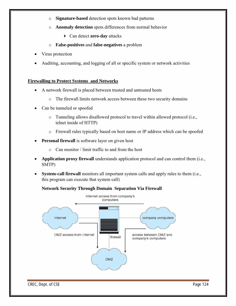
CREC, Dept. of CSE Page 124
o Signature-based detection spots known bad patterns
o Anomaly detection spots differences from normal behavior
4 Can detect zero-day attacks
o False-positives and false-negatives a problem
∑ Virus protection
∑ Auditing, accounting, and logging of all or specific system or network activities
Firewalling to Protect Systems and Networks
∑ A network firewall is placed between trusted and untrusted hosts
o The firewall limits network access between these two security domains
∑ Can be tunneled or spoofed
o Tunneling allows disallowed protocol to travel within allowed protocol (i.e., telnet inside of HTTP)
o Firewall rules typically based on host name or IP address which can be spoofed
∑ Personal firewall is software layer on given host
o Can monitor / limit traffic to and from the host
∑ Application proxy firewall understands application protocol and can control them (i.e., SMTP)
∑ System-call firewall monitors all important system calls and apply rules to them (i.e., this program can execute that system call)
Network Security Through Domain Separation Via Firewall
CREC, Dept. of CSE Page 125
Computer Security Classifications:
∑ U.S. Department of Defense outlines four divisions of computer security: A, B, C, and D
∑ D – Minimal security
∑ C – Provides discretionary protection through auditing
o Divided into C1 and C2
4 C1 identifies cooperating users with the same level of protection
4 C2 allows user-level access control
4 B – All the properties of C, however each object may have unique sensitivity labels
o Divided into B1, B2, and B3
o A – Uses formal design and verification techniques to ensure security