operating instructions excellence analytical …physics.ucsd.edu/neurophysics/manuals/mettler...
TRANSCRIPT

www.mt.com
XS204 Delta Range
XS Models – Part 1O
pera
ting
Inst
ruct
ions Excellence Analytical Balances

Table of contents
Introduction1 5
Conventions and Symbols Used in These Operating Instructions1.1 6
Safety Information2 7
Definition of Signal Warnings and Symbols2.1 7Product Specific Safety Notes2.2 7
Overview XS Analytical Balance3 9
Setting up the Balance4 10
Unpacking and Checking the Delivered Items4.1 10Unpacking the Balance4.1.1 10Scope of Delivery4.2 11Selecting a Location and Leveling the Balance4.3 12Location4.3.1 12Leveling the Balance4.3.2 12Assembling the Balance4.4 13Power Supply4.5 15Left/Right Operating of the Glass Draft Shield4.6 16Setting the Reading Angle and Positioning the Terminal4.7 16Optimise the Readability of the Terminal4.7.1 16Remove Terminal and Place Close to the Balance4.7.2 16Transporting the Balance4.8 17Transporting Over Short Distances4.8.1 17Transporting Over Long Distances4.8.2 18Below-the-Balance Weighing4.9 20Installing the ErgoClip4.10 20Installing the Single-use Aluminum Weighing Pan4.11 21Installing the Grid Weighing Pan Cover4.12 21
Maintenance5 23
Cleaning5.1 23Disposal5.2 23
Technical Data6 24
General Data6.1 24Explanatory Notes for the METTLER TOLEDO AC Adapter6.2 24Model-specific Data6.3 25Dimensions6.4 28Interfaces6.5 29Specifications of RS232C6.5.1 29Specifications of "Aux" Connection6.5.2 29
Accessories and Spare Parts7 30
Accessories7.1 30Spare Parts7.2 41
Table of contents 3

Appendix8 42
MT-SICS Interface Commands and Functions8.1 42Procedure for Certified Balances8.2 42
Index9 44
Table of contents4
1 IntroductionThank you for choosing a METTLER TOLEDO balance.
The balances of the XS line combine a large number of weighing and adjustment possibilities with exceptionallyconvenient operation.
In this chapter you will be given basic information about your balance. Please read right through this chaptercarefully even if you already have experience with METTLER TOLEDO balances. Please pay special attention tothe safety warnings!
The different models have different characteristics regarding equipment and performance. Special notes in thetext indicate where this makes a difference to operation.
The XS line comprises a range of balances which differ from each other in relation to their weighing range andresolution.
The following features are common to all models of the XS lines:
Fully automatic adjustment "FACT" using internal weight.
Built-in applications for normal weighing, statistics, formulation, density, percent weighing, piece countingand LabX Client.
Integral RS232C interface.
Slot for second interface (optional).
Touch-sensitive graphics terminal ("Touch Screen") for easy, convenient operation.
A brief word about standards, guidelines, and methods of quality assurance: The balances comply with usualstandards and guidelines. They support standard procedures, specifications, working methods, and reportsaccording to GLP (Good Laboratory Practice). In this connection, records of working procedures and adjustments become very important; for this purpose we recommend you to use a printer from the METTLER TOLEDOrange, since these are optimally adapted to your balance. The balances conform to the applicable standardsand guidelines and possess a EC declaration of conformity. METTLER TOLEDO is certified as manufactureraccording to ISO 9001 and ISO 14001.
The Operating Instructions for the XS balances consist of 3 separate documents, whose contents are listedbellow.
Part 1, This DocumentContents
Introduction Safety Information Setting up the Balance Leveling the Balance Cleaning and Service Technical Data Interface commands and MT-SICS functions Accessories Spare Parts
Part 2, Separate DocumentContents: Terminal, System and Applications
Basic Principles for Using the Terminal and the Firmware System Settings Applications Firmware (Software) Updates Error and Status Messages
5Introduction
6 Introduction
Conversion Table for Weight Units Recommended Printer Settings
Part 3, Separate DocumentContents: Adjustments and Tests
Adjustments Tests
Finding More InformationInternet http://www.mt.com/excellence
1.1 Conventions and Symbols Used in These Operating InstructionsThe following conventions apply to the operating instructions: Part 1, Part 2 and Part 3.
Key designations are indicated by a picture or text in double angular parentheses (e.g. « » or «On/Off»).
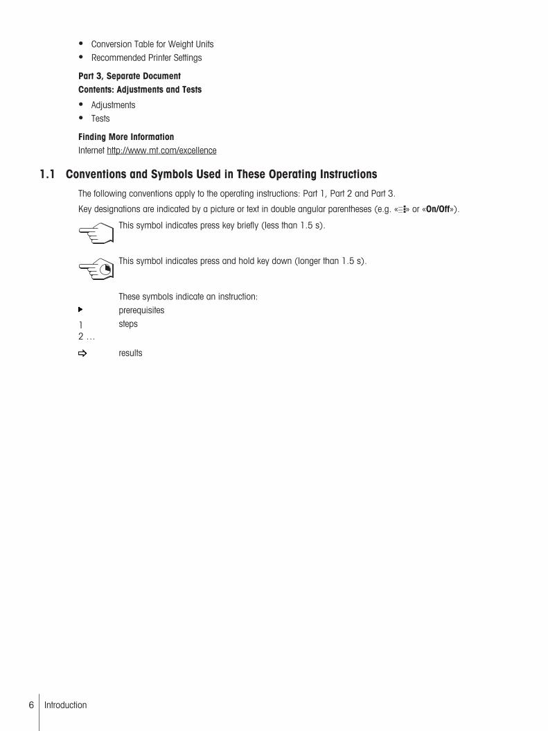
This symbol indicates press key briefly (less than 1.5 s).
This symbol indicates press and hold key down (longer than 1.5 s).
These symbols indicate an instruction:prerequisites
1
2 …
steps
results

2 Safety Information
2.1 Definition of Signal Warnings and SymbolsSafety notes are marked with signal words and warning symbols. These show safety issues and warnings.Ignoring the safety notes may lead to personal injury, damage to the balance, malfunctions and false results.
Signal Words
WARNING for a hazardous situation with medium risk, possibly resulting in severeinjuries or death if not avoided.
CAUTION for a hazardous situation with low risk, resulting in damaged to the deviceor the property or in losing of data or minor or medium injuries if not avoided.
Attention (no symbol)for important information about the product.
Note (no symbol)for useful information about the product.
Warning Symbols
General hazard Electrical shock
2.2 Product Specific Safety NotesAlways operate and use your balance only in accordance with the Operating Instructions Part 1, Part 2 andPart 3.
The instructions for setting up your new balance must be strictly observed.
If the instrument is not used according to the manufacturer’s Operating Instructions (Part 1, Part 2 andPart 3), protection of the instrument may be impaired.
Intended UseYour balance is used for weighing. Use the balance exclusively for this purpose. Any other type of use andoperation beyond the limits of technical specifications without written consent from Mettler-Toledo AG, is considered as not intended.
It is not permitted to use the instrument in explosive atmosphere of gases, steam, fog, dustand flammable dust (hazardous environments).
7Safety Information
8 Safety Information
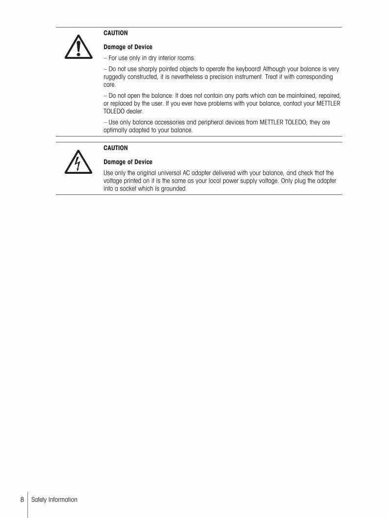
CAUTION
Damage of Device
– For use only in dry interior rooms.
– Do not use sharply pointed objects to operate the keyboard! Although your balance is veryruggedly constructed, it is nevertheless a precision instrument. Treat it with correspondingcare.
– Do not open the balance: It does not contain any parts which can be maintained, repaired,or replaced by the user. If you ever have problems with your balance, contact your METTLERTOLEDO dealer.
– Use only balance accessories and peripheral devices from METTLER TOLEDO; they areoptimally adapted to your balance.
CAUTION
Damage of Device
Use only the original universal AC adapter delivered with your balance, and check that thevoltage printed on it is the same as your local power supply voltage. Only plug the adapterinto a socket which is grounded.

3 Overview XS Analytical Balance
www.mt.com
XS204 Delta Range
1
65
2
3
4
7
8
9
10
11
12
14
15
13
161718
Overview
1 Terminal (details see Operating Instructions –Part 2)
2 Display (Touch-sensitive "Touch Screen")
3 Operating keys 4 Drip tray5 Handle for variable operation of the draft-shield
side doors6 Grid weighing pan
7 Glass draft shield 8 Type name9 Handle for operation of the draft-shield top door 10 Guide for top door of draft shield and handle for
transport11 Level indicator 12 Foot screw13 Slot for second interface (optional) 14 Socket for AC adapter15 Fastening point for anti-theft device 16 RS232C serial interface17 Aux 2 (connection for "ErgoSens", hand- or
foot-switch)18 Aux 1 (connection for "ErgoSens", hand- or
foot-switch)
9Overview XS Analytical Balance

10 Overview XS Analytical Balance
4 Setting up the BalanceThis chapter explains how to unpack your new balance, and how to set it up and prepare it for operation. Whenyou have carried out the steps described in this chapter, your balance is ready for operation.
4.1 Unpacking and Checking the Delivered Items
4.1.1 Unpacking the Balance
Use the lifting strap to lift the balance out of the packaging carton.
Overview
1 Lifting strap2 Top packing cushion3 Operating Instructions and other important documents4 Balance5 Set with draft-shield doors and terminal support6 Set with AC adapter, power supply cable, drip tray, grid weighing
pan, grid weighing pan cover, set of single-use pans and ErgoClip "Basket" (basket for small weighing objects)
7 Terminal
NoteThe terminal is connected to the balance by a cable!
8 Bottom packing cushion
8
1
2
3
4
5
67
1 Unfasten lifting strap (1).
2 Remove top packing cushion (2).
1 Pull out Operating Instructions (3).
2 Remove set with AC adapter etc. (4).
3 Remove set with draft-shield doors etc. (5).

– Carefully pull the terminal out of the bottom packing cushion andremove the protective cover.
NoteThe terminal is connected to the balance by a cable, so only pull theterminal just far enough out of the packing cushion to remove the protective cover.
1 Place the terminal on the front of the balance.
2 Hold the balance by the guide or handle, hold the terminal firmlywith your other hand, and pull the balance and terminal togetherout of the bottom packing cushion.
1 Place the balance with the terminal in the place where the balancewill be used for weighing.
2 Remove the cover from the balance.
3 Pull the transport protection (9) of the weighing pan supporttoward the front and off.
9
NotePlease keep all parts of the packaging. This packaging guarantees best possible protection of your balance fortransportation, see Transporting the Balance (page 17).
4.2 Scope of DeliveryThe standard scope of delivery contains the following items:
Balance with terminal• RS232C interface• Slot for second interface (optional)• Feedthroughs for below-the-balance weighing and for antitheft device
11Setting up the Balance
12 Setting up the Balance
Set with draft-shield doors and terminal support
Grid weighing pan
Grid weighing pan cover of chrome-nickel steel (attachment for grid weighing pan)
Set of single-use aluminum weighing pans (10 pans) for mounting on the grid weighing pan
Drip tray
AC adapter with country-specific power cable
Protective cover for the terminal
Cleaning brush
ErgoClip "Basket" (basket for small weighing objects)
Production certificate
CE declaration of conformity
Operating Instructions Part 1 (this document), Part 2 and Part 3
Instructions for unpacking, re-packing, and setting up
4.3 Selecting a Location and Leveling the Balance
4.3.1 Location
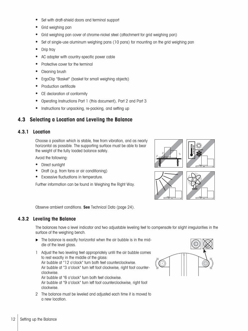
Choose a position which is stable, free from vibration, and as nearlyhorizontal as possible. The supporting surface must be able to bearthe weight of the fully loaded balance safely.
Avoid the following:
Direct sunlight Draft (e.g. from fans or air conditioning) Excessive fluctuations in temperature.
Further information can be found in Weighing the Right Way.
Observe ambient conditions. See Technical Data (page 24).
4.3.2 Leveling the Balance
The balances have a level indicator and two adjustable leveling feet to compensate for slight irregularities in thesurface of the weighing bench.
The balance is exactly horizontal when the air bubble is in the middle of the level glass.
1 Adjust the two leveling feet appropriately until the air bubble comesto rest exactly in the middle of the glass:Air bubble at "12 o'clock" turn both feet counterclockwise.Air bubble at "3 o'clock" turn left foot clockwise, right foot counterclockwise.Air bubble at "6 o'clock" turn both feet clockwise.Air bubble at "9 o'clock" turn left foot counterclockwise, right footclockwise.
2 The balance must be leveled and adjusted each time it is moved toa new location.
4.4 Assembling the Balance
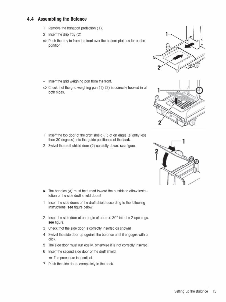
1 Remove the transport protection (1).
2 Insert the drip tray (2).
Push the tray in from the front over the bottom plate as far as thepartition.
– Insert the grid weighing pan from the front.
Check that the grid weighing pan (1) (2) is correctly hooked in atboth sides.
1 Insert the top door of the draft shield (1) at an angle (slightly lessthan 30 degrees) into the guide positioned at the back.
2 Swivel the draft-shield door (2) carefully down, see figure.
The handles (A) must be turned toward the outside to allow installation of the side draft shield doors!
1 Insert the side doors of the draft shield according to the followinginstructions, see figure below.
2 Insert the side door at an angle of approx. 30° into the 2 openings,see figure.
3 Check that the side door is correctly inserted as shown!
4 Swivel the side door up against the balance until it engages with aclick.
5 The side door must run easily, otherwise it is not correctly inserted.
6 Insert the second side door of the draft shield.
The procedure is identical.
7 Push the side doors completely to the back.
13Setting up the Balance
14 Setting up the Balance
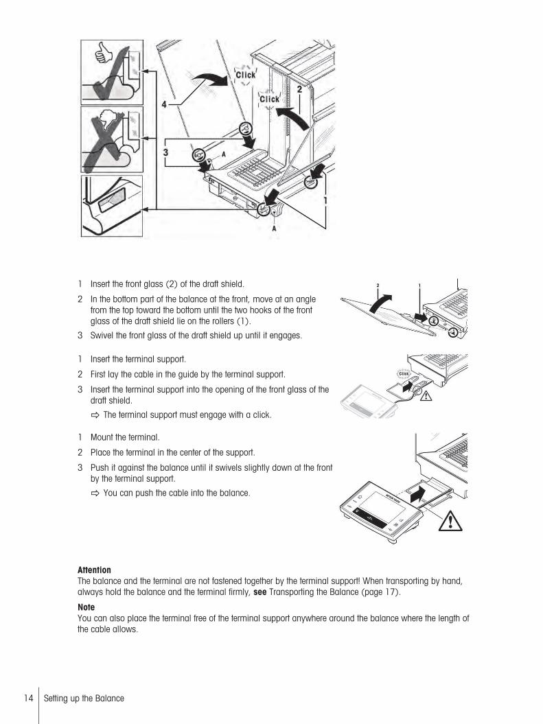
1 Insert the front glass (2) of the draft shield.
2 In the bottom part of the balance at the front, move at an anglefrom the top toward the bottom until the two hooks of the frontglass of the draft shield lie on the rollers (1).
3 Swivel the front glass of the draft shield up until it engages.
1 Insert the terminal support.
2 First lay the cable in the guide by the terminal support.
3 Insert the terminal support into the opening of the front glass of thedraft shield.
The terminal support must engage with a click.
1 Mount the terminal.
2 Place the terminal in the center of the support.
3 Push it against the balance until it swivels slightly down at the frontby the terminal support.
You can push the cable into the balance.
AttentionThe balance and the terminal are not fastened together by the terminal support! When transporting by hand,always hold the balance and the terminal firmly, see Transporting the Balance (page 17).
NoteYou can also place the terminal free of the terminal support anywhere around the balance where the length ofthe cable allows.
4.5 Power Supply
WARNING
Risk of electric shock
– Ensure that the AC power pack for the balance is only used in accordance with the specifications listed in chapter General Data.
– Your instrument is supplied with a 3-pin power cable with an equipment grounding conductor. Only extension cables which meet this relevant standards and also have an equipment grounding conductor may be used. Intentional disconnection of the equipment grounding conductor is prohibited.
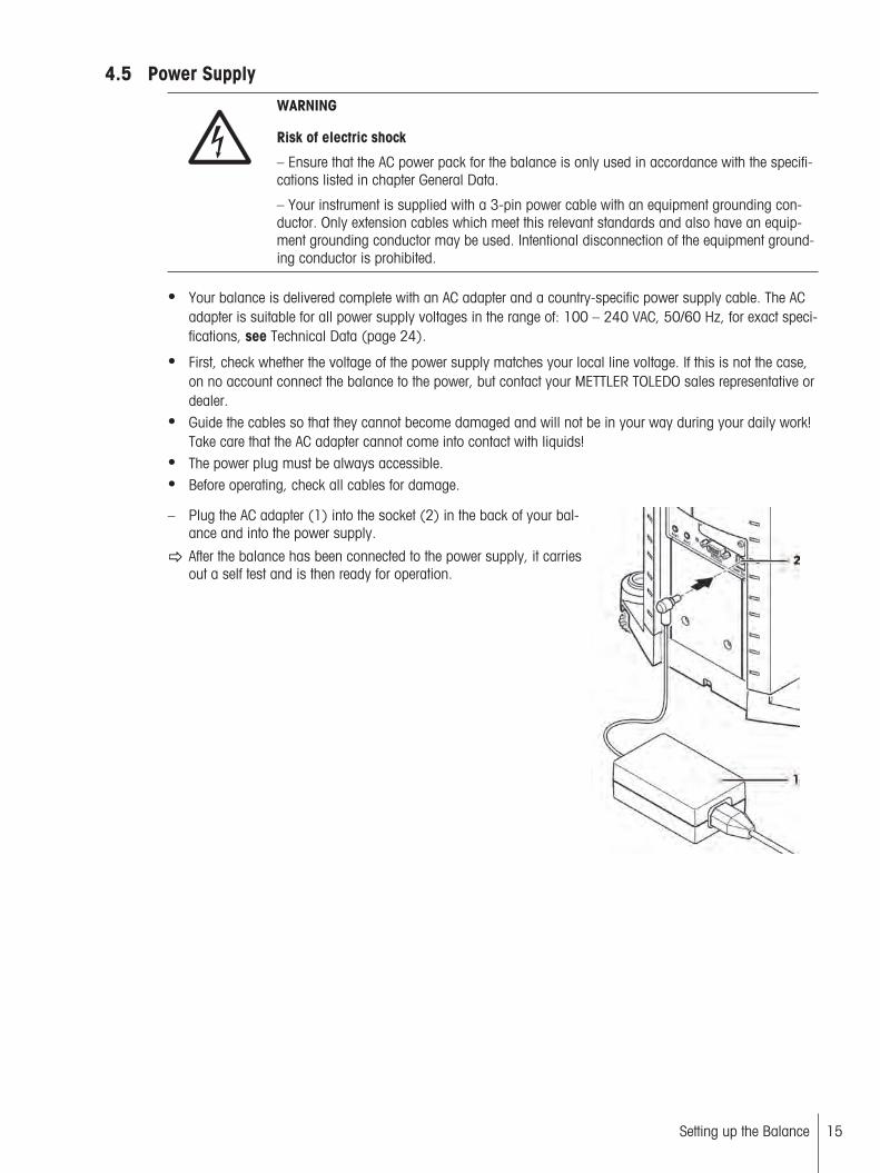
Your balance is delivered complete with an AC adapter and a country-specific power supply cable. The ACadapter is suitable for all power supply voltages in the range of: 100 – 240 VAC, 50/60 Hz, for exact specifications, see Technical Data (page 24).
First, check whether the voltage of the power supply matches your local line voltage. If this is not the case,on no account connect the balance to the power, but contact your METTLER TOLEDO sales representative ordealer.
Guide the cables so that they cannot become damaged and will not be in your way during your daily work!Take care that the AC adapter cannot come into contact with liquids!
The power plug must be always accessible. Before operating, check all cables for damage.
– Plug the AC adapter (1) into the socket (2) in the back of your balance and into the power supply.
After the balance has been connected to the power supply, it carriesout a self test and is then ready for operation.
15Setting up the Balance

16 Setting up the Balance
NoteIf the display field remains dark, even though the power supply connection functions.
1 First disconnect the balance from the power supply.
2 Open the terminal.
3 Press both buttons (1) on the back of the terminal and open theupper part of the terminal.
4 Check that the plug for the terminal cable (2) is connected correctlyinside the terminal.
1
1 2
4.6 Left/Right Operating of the Glass Draft ShieldThe glass draft shield of your balance can be adapted to the environmental conditions and your weighing style,as well as to the type of weighing and loading.
The position of the handles determines which door(s) of the draftshield (left, right, or both) is/are opened.
Try various different combinations by moving the external handles intothe upper or lower position. We recommend you to set up the glassdraft shield so that it only opens on the side where the balance is loaded. Your balance then works faster, because there are fewer troublesome currents of air than when both doors of the draft shield areopened together.
4.7 Setting the Reading Angle and Positioning the Terminal
4.7.1 Optimise the Readability of the Terminal
Changing the reading angle
1 For a steeper reading angle, pull both levers (1) at the sideupward.
You can then pull the upper part of the terminal slowly upwarduntil it engages in the desired position. A total of 3 setting positions are available.
2 Move it in an appropriate position.
3 For a flatter reading angle, pull both levers (1) at the side upward,and press the lower part of the terminal downward.
4 Release both levers and the upper part of the terminal then engagesin the desired position.
1 1
4.7.2 Remove Terminal and Place Close to the Balance
The terminal is connected to the balance by a cable. So you can arrange your workplace optimally, the terminalcan be removed from the balance and placed separately.

Place the terminal separately
1 Switch the balance off.
2 Carefully lift the terminal off the terminal support.You can leave the terminal support on the balance or remove it.
3 Pull the cable carefully out from the balance as far as possible.
4 Place the terminal where you want it to be.
NoteThe cable can also be led out of the back of the balance. If workingthis way would be convenient for you, call your METTLER TOLEDOdealer who will adapt the balance for you.
4.8 Transporting the Balance1 Switch off the balance.
2 The balance must be disconnected from the power supply.
3 Remove any interface cable from the balance.
4.8.1 Transporting Over Short Distances
If you wish to move your balance over a short distance to a new location, proceed as follows.
CAUTION
Damage of Device
Never lift the balance by the glass draft shield, as this can cause damage!
1 With one hand, hold the balance by the guide for the top door ofthe draft shield.
2 With your other hand, hold the terminal. The terminal is not rigidlyfastened to the balance, so you must always hold the balance withone hand and the terminal with the other.
3 Carefully lift the balance and carry it to its new location, observethe notes in chapter Location (page 12).
17Setting up the Balance

18 Setting up the Balance
4.8.2 Transporting Over Long Distances
If you want to transport or ship your balance over long distances, or if it is not certain that the balance will betransported upright, use the complete original packaging.
Disassemble the following parts
1 Lift the terminal (1) out of the terminal support and place it next tothe support.
2 Pull the terminal support (2) off the balance.
3 Swivel the front glass (3) of the draft shield away from the balance.
4 Carefully fold the side doors (4+5) of the draft shield against therespective handles and pull the side doors out of the guide.
5 Swivel the front ot the top door (6) of the draft shield up and pullthe door out of the guide.
6 Carefully raise the front of the grid weighing pan (7) and lift it outof the guide.
7 Pull the drip tray (8) toward the front and out.
Pack the draft shield, the intermediate shelf and the terminal support (Pos. 2-6)
– Place these parts in the compartments provided in the originalpackaging.NoteWe advise you to place a sheet of paper between the sides glassesof the draft shield.
Pack the AC adapter, the power supply cable, and the individual parts (steps 7+8)
1 Place the AC adapter and the power supply cable in the packaging.
2 Place the drip tray (8) upside down in the packaging.
3 Place the grid weighing pan (7) upside down on the drip tray.
4 Place the ErgoClip "Basket" in the packaging.
CAUTION
Damage of Device
These instructions must be followed exactly, otherwise the balance may be damaged wheninserting it into the packing cushions.
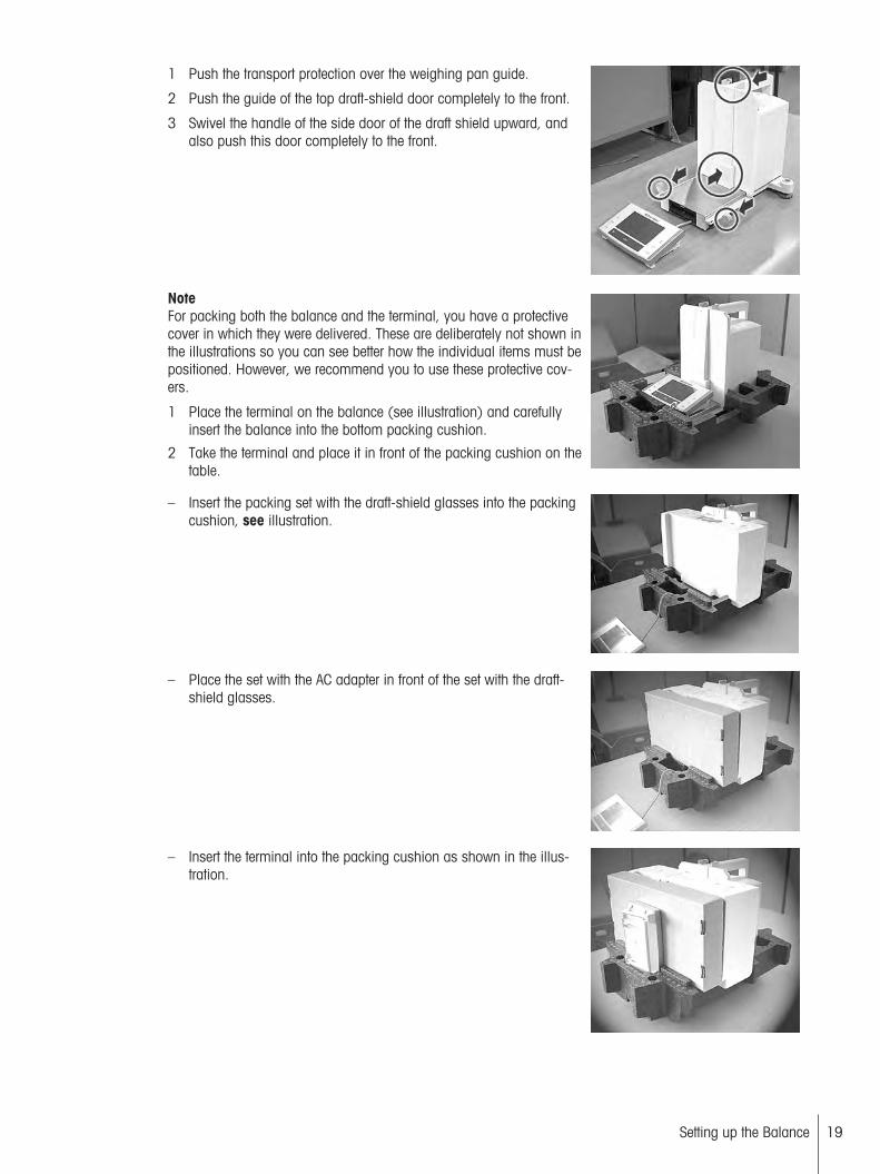
1 Push the transport protection over the weighing pan guide.
2 Push the guide of the top draft-shield door completely to the front.
3 Swivel the handle of the side door of the draft shield upward, andalso push this door completely to the front.
NoteFor packing both the balance and the terminal, you have a protectivecover in which they were delivered. These are deliberately not shown inthe illustrations so you can see better how the individual items must bepositioned. However, we recommend you to use these protective covers.
1 Place the terminal on the balance (see illustration) and carefullyinsert the balance into the bottom packing cushion.
2 Take the terminal and place it in front of the packing cushion on thetable.
– Insert the packing set with the draft-shield glasses into the packingcushion, see illustration.
– Place the set with the AC adapter in front of the set with the draft-shield glasses.
– Insert the terminal into the packing cushion as shown in the illustration.
19Setting up the Balance
20 Setting up the Balance
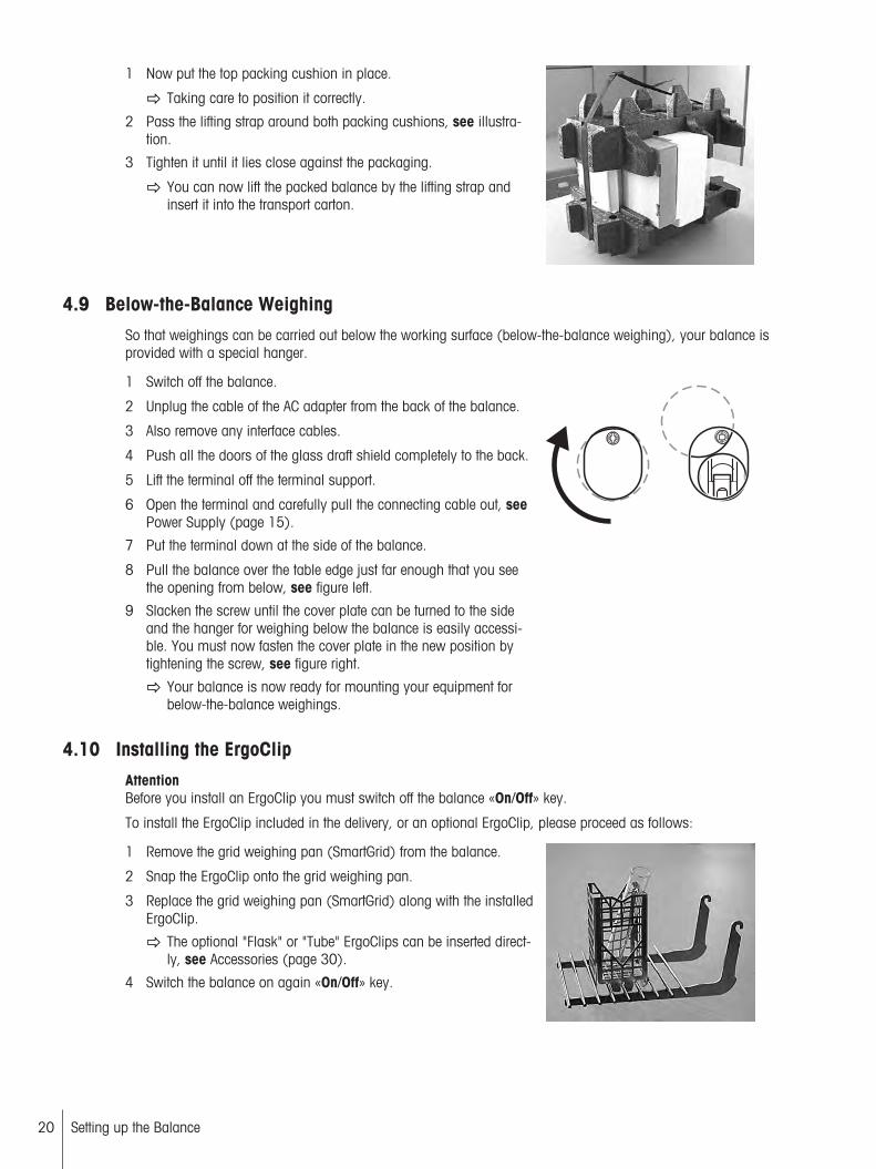
1 Now put the top packing cushion in place.
Taking care to position it correctly.
2 Pass the lifting strap around both packing cushions, see illustration.
3 Tighten it until it lies close against the packaging.
You can now lift the packed balance by the lifting strap andinsert it into the transport carton.
4.9 Below-the-Balance WeighingSo that weighings can be carried out below the working surface (below-the-balance weighing), your balance isprovided with a special hanger.
1 Switch off the balance.
2 Unplug the cable of the AC adapter from the back of the balance.
3 Also remove any interface cables.
4 Push all the doors of the glass draft shield completely to the back.
5 Lift the terminal off the terminal support.
6 Open the terminal and carefully pull the connecting cable out, seePower Supply (page 15).
7 Put the terminal down at the side of the balance.
8 Pull the balance over the table edge just far enough that you seethe opening from below, see figure left.
9 Slacken the screw until the cover plate can be turned to the sideand the hanger for weighing below the balance is easily accessible. You must now fasten the cover plate in the new position bytightening the screw, see figure right.
Your balance is now ready for mounting your equipment forbelow-the-balance weighings.
4.10 Installing the ErgoClipAttentionBefore you install an ErgoClip you must switch off the balance «On/Off» key.
To install the ErgoClip included in the delivery, or an optional ErgoClip, please proceed as follows:
1 Remove the grid weighing pan (SmartGrid) from the balance.
2 Snap the ErgoClip onto the grid weighing pan.
3 Replace the grid weighing pan (SmartGrid) along with the installedErgoClip.
The optional "Flask" or "Tube" ErgoClips can be inserted directly, see Accessories (page 30).
4 Switch the balance on again «On/Off» key.

Important to know!If you do not switch the balance off before you do the installation, the FACT function is not activated.
ReasonAddition of the ErgoClip causes the dead-load tolerance range of the balance to be exceeded. The balancetherefore does not activate FACT, so as not to interrupt the assumed weighing operation.
When this status icon appears in the display, it means: "The balancewants to execute FACT" but cannot.
4.11 Installing the Single-use Aluminum Weighing PanNoteFor standard operation with conventional tare containers, we do not recommend using this weighing pan. Itsuse may affect the stabilization time and degree of accuracy. The listed specifications are reached without asingle-use weighing pan.
CAUTION
Hand injuries
Take care when handling the aluminum weighing pan, the corners and edges are extremelysharp!
– To install the single-use aluminum weighing pan, remove the grid weighing pan from the weighing chamber, see Assembling the Balance (page 13).
Only to be used for weighing highly-specialized tare containers.
1 Place the single-use aluminum weighing pan onto the grid weighing pan from above.
2 Fold the 4 side flaps under the bars of the grid weighing pan.
4.12 Installing the Grid Weighing Pan CoverNoteFor standard operation with conventional tare containers, we do not recommend using this weighing pan. Itsuse may affect the stabilization time and degree of accuracy. The listed specifications are reached without aweighing pan.
CAUTION
Hand injuries
Take care when handling the weighing pan, the corners and edges are extremely sharp!
AttentionWith installed grid weighing pan cover, the balance does not switch to "Standby" mode!
21Setting up the Balance
22 Setting up the Balance
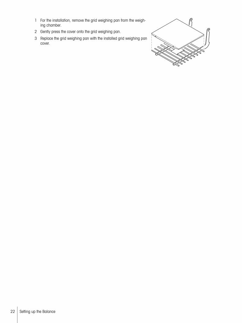
1 For the installation, remove the grid weighing pan from the weighing chamber.
2 Gently press the cover onto the grid weighing pan.
3 Replace the grid weighing pan with the installed grid weighing pancover.
5 Maintenance
5.1 CleaningPeriodically clean the weighing pan, the drip tray, the housing, and the terminal of your balance using thebrush supplied with it. The maintenance interval depends on your standard operating procedure (SOP).
Please observe the following notes
WARNING
Damage of balance
- The balance must be disconnected from the power supply.
- Ensure that no liquid comes into contact with the balance, the terminal or the AC adapter.
- Never open the balance, terminal or AC adapter – they contain no components, which canbe cleaned, repaired or replaced by the user.
CAUTION
Damage of balance
On no account use cleaning agents which contain solvents or abrasive ingredients, as thiscan result in damage to the terminal overlay.
Cleaning
Your balance is made from high quality, resistant materials and can therefore be cleaned with a commerciallyavailable, mild cleaning agent.
1 To clean the weighing chamber thoroughly, swivel the glasses of the draft shield away from the balanceand pull them out of their fastenings.
2 Carefully raise the front of the weighing pan and lift it out of the guide.
3 Pull the drip tray away from the balance.
4 When you replace these parts, make sure they are in the correct position.
NotePlease contact your METTLER TOLEDO dealer for details of the available service options. Regular servicing byan authorized service engineer ensures constant accuracy for years to come and prolongs the service life ofyour balance.
5.2 Disposal
In conformance with the European Directive 2002/96/EC on Waste Electrical and ElectronicEquipment (WEEE) this device may not be disposed of in domestic waste. This also appliesto countries outside the EU, per their specific requirements.
Please dispose of this product in accordance with local regulations at the collecting pointspecified for electrical and electronic equipment. If you have any questions, please contactthe responsible authority or the distributor from which you purchased this device. Should thisdevice be passed on to other parties (for private or professional use), the content of this regulation must also be related.
Thank you for your contribution to environmental protection.
23Maintenance
24 Maintenance
6 Technical Data
6.1 General Data
CAUTION
Use only with a tested AC Adapter with SELV output current.Ensure correct polarity
Power supplyPower supply connector with AC/DCadapter:
11107909Primary: 100-240 VAC, -15%/+10%, 50/60 HzSecondary: 12 VDC ±/-3%, 2.0 A (with electronic overload protection)
Cable to AC adapter: Design: 3-core, with country-specific plugNoteMake sure the power supply plug is freely accessible
Power supply to the balance: 12 VDC ±/-3%, 2.0 A, maximum ripple: 80 mVDCpp
Protection and standardsOvervoltage category: Class IIDegree of pollution: 2Protection: Protected against dust and waterStandards for safety and EMC: See Declaration of ConformityRange of application: For use only in closed interior rooms
Environmental conditionsHeight above mean sea level: Up to 4000 mAmbient temperature: 5-40 °CRelative air humidity: Max. 80% at 31 °C, linearly decreasing to 50% at 40 °C, non
condensingWarm-up time: At least 120 minutes after connecting the balance to the power
supply; when switched on from standby-mode, the balance isready for operation immediately
MaterialsHousing: Die-cast aluminum, lacquered, plastic and chrome steelTerminal: Die-cast zinc, lacquered, and plasticGrid weighing pan: Chrome-nickel steel X5CrNi18-10
6.2 Explanatory Notes for the METTLER TOLEDO AC AdapterThe certified external power supply which conforms to the requirements for Class II double insulated equipmentis not provided with a protective earth connection but with a functional earth connection for EMC purposes. Thisearth connection IS NOT a safety feature. Further information about conformance of our products can be foundin the brochure "Declaration of Conformity" which is coming with each product.
In case of testing with regard to the European Directive 2001/95/EC the power supply and the balance have tobe handled as Class II double insulated equipment.
Consequently an earth bonding test is not required. Similarly it is not necessary to carry out an earth bondingtest between the supply earth conductor and any exposed metalwork on the balance.

Because the balance are sensitive to static charges a leakage resistor, typically 10 kΩ, is connected betweenthe earth connector and the power supply output terminals. The arrangement is shown in the equivalent circuitdiagram. This resistor is not part of the electrical safety arrangement and does not require testing at regularintervals.
10 kΩ coupling resistor for
electrostatic discharge
Input 100…240 VAC Output 12 VDC
Double Insulation
Plastic Housing
P
N
E
AC
DC
Equivalent circuit diagram
6.3 Model-specific DataXS64 XS104 XS204DR
Limit valuesMaximum capacity 61 g 120 g 220 gReadability 0.1 mg 0.1 mg 1 mgTare range (from…to) 0 … 61 g 0 … 120 g 0 … 220 gMaximum capacity, fine range – – 81 gReadability, fine range – – 0.1 mgRepeatability (at nominal load) sd 0.1 mg (60 g) 0.1 mg (100 g) 0.7 mg (200 g) Repeatability (at low load) sd 0.07 mg (10 g) 0.07 mg (10 g) 0.5 mg (10 g) Repeatability, fine range (at low load) sd – – 0.1 mg (10 g) Linearity deviation 0.2 mg 0.2 mg 1 mg Eccentricity deviation (test load) 0.15 mg (20 g) 0.3 mg (50 g) 0.3 mg (100 g) Sensitivity offset (test weight) 0.9 mg (60 g) 1 mg (100 g) 1 mg (200 g) Sensitivity temperature drift 1) 0.00015%/°C 0.00015%/°C 0.00015%/°C Sensitivity stability 0.0002%/a 0.0002%/a 0.0002%/a Typical valuesRepeatability sd 0.04 mg 0.04 mg 0.4 mg Repeatability, fine range sd – – 0.04 mg Linearity deviation 0.1 mg 0.13 mg 0.3 mgEccentric deviation (test load) 0.06 mg (20 g) 0.15 mg (50 g) 0.16 mg (100 g) Sensitivity offset (test load) 1.2 mg (60 g) 0.6 mg (100 g) 0.8 mg (200 g) Minimum sample weight (according to USP) 120 mg 120 mg 1200 mg Minimum sample weight (according to USP),fine range
– – 120 mg
Minimum sample weight(U=1%, k=2)
8 mg 8 mg 80 mg
Minimum sample weight(U=1%, k=2), fine range
– – 8 mg
Settling time 1.5 s 1.5 s 1.5 s Settling time, fine range – – 1.5 s DimensionsBalance dimensions (WxDxH) 263x453x322 mm 263x453x322 mm 263x453x322 mm Weighing pan dimensions 78x73 mm (WxD) 78x73 mm (WxD) 78x73 mm (WxD) Typical uncertainties and supplementary dataRepeatability sd 0.04mg
+0.000015%·Rgr 0.04mg+0.00002%·Rgr
0.4mg+0.00005%·Rgr
25Technical Data

26 Technical Data
XS64 XS104 XS204DRRepeatability, fine range sd – – 0.04mg
+0.00002%·Rgr Differential linearity deviation sd √(40pg·Rnt) √(40pg·Rnt) √(120pg·Rnt) Differential eccentric load deviation sd 0.00015%·Rnt 0.00015%·Rnt 0.00008%·Rnt Sensitivity offset sd 0.001%·Rnt 0.0003%·Rnt 0.0002%·Rnt Minimum sample weight (according to USP) 120mg+0.045%·Rgr 120mg+0.06%·Rgr 1200mg+0.15%·Rgr Minimum sample weight (according to USP),fine range
– – 120mg+0.06%·Rgr
Minimum sample weight(U=1%, k=2)
8mg+0.003%·Rgr 8mg+0.004%·Rgr 80mg+0.01%·Rgr
Minimum sample weight(U=1%, k=2), fine range
– – 8mg+0.004%·Rgr
Weighing time 4 s 4 s 3.5 s Weighing time, fine range – – 4 s Interface update rate 23/s 23/s 23/s Usable height of draft shield 235 mm 235 mm 235 mm Weight of balance 9.1 kg 9.1 kg 9.1 kg Number of built-in reference weights 2 2 2Weights for routine testingOIML CarePac
Weights
50 g F2, 2 g E2
#11123003
100 g F2, 5 g E2
#11123002
200 g F2, 10 g F1
#11123001
ASTM CarePac
Weights
50 g 1, 2 g 1
#11123103
100 g 1, 5 g 1
#11123102
200 g 1, 10 g 1
#11123101
sd = Standard deviation Rnt = Net weight (sample weight)
Rgr = Gross weight a = Year (annum)
1) In the temperature range 10…30 °C
XS204 XS105DU XS205DULimit valuesMaximum capacity 220 g 120 g 220 gReadability 0.1 mg 0.1 mg 0.1 mg Tare range (from…to) 0 … 220 g 0 … 120 g 0 … 220 g Maximum capacity, fine range – 41 g 81 g Readability, fine range – 0.01 mg 0.01 mg Repeatability (at nominal load) sd 0.1 mg (200 g) 0.1 mg (100 g) 0.1 mg (200 g) Repeatability (at low load) sd 0.07 mg (10 g) 0.05 mg (10 g) 0.05 mg (10 g) Repeatability, fine range (at low load) sd – 0.02 mg (10 g) 0.02 mg (10 g) Linearity deviation 0.2 mg 0.2 mg 0.2 mgEccentricity deviation (test load) 0.3 mg (100 g) 0.3 mg (50 g) 0.3 mg (100 g) Sensitivity offset (test weight) 1 mg (200 g) 0.8 mg (100 g) 0.8 mg (200 g) Sensitivity temperature drift 1) 0.00015%/°C 0.00015%/°C 0.00015%/°C Sensitivity stability 0.0002%/a 0.0002%/a 0.0002%/a Typical valuesRepeatability sd 0.04 mg 0.04 mg 0.04 mg Repeatability, fine range sd – 0.01 mg 0.01 mg Linearity deviation 0.13 mg 0.13 mg 0.13 mg Eccentric deviation (test load) 0.16 mg (100 g) 0.15 mg (50 g) 0.16 mg (100 g) Sensitivity offset (test load) 0.8 mg (200 g) 0.4 mg (100 g) 0.6 mg (200 g) Minimum sample weight (according to USP) 120 mg 120 mg 120 mg Minimum sample weight (according to USP),fine range
– 30 mg 30 mg
Minimum sample weight(U=1%, k=2)
8 mg 8 mg 8 mg
Minimum sample weight(U=1%, k=2), fine range
– 2 mg 2 mg
Settling time 1.5 s 1.5 s 1.5 s Settling time, fine range – 3 s 3 s
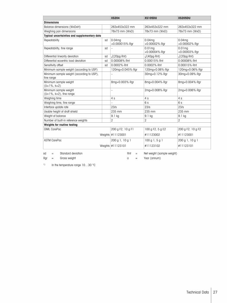
XS204 XS105DU XS205DUDimensionsBalance dimensions (WxDxH) 263x453x322 mm 263x453x322 mm 263x453x322 mm Weighing pan dimensions 78x73 mm (WxD) 78x73 mm (WxD) 78x73 mm (WxD) Typical uncertainties and supplementary dataRepeatability sd 0.04mg
+0.000015%·Rgr 0.04mg+0.00002%·Rgr
0.04mg+0.00002%·Rgr
Repeatability, fine range sd – 0.01mg+0.00004%·Rgr
0.01mg+0.00003%·Rgr
Differential linearity deviation sd √(20pg·Rnt) √(40pg·Rnt) √(20pg·Rnt) Differential eccentric load deviation sd 0.00008%·Rnt 0.00015%·Rnt 0.00008%·Rnt Sensitivity offset sd 0.0002%·Rnt 0.0002%·Rnt 0.00015%·Rnt Minimum sample weight (according to USP) 120mg+0.045%·Rgr 120mg+0.06%·Rgr 120mg+0.06%·Rgr Minimum sample weight (according to USP),fine range
– 30mg+0.12%·Rgr 30mg+0.09%·Rgr
Minimum sample weight(U=1%, k=2)
8mg+0.003%·Rgr 8mg+0.004%·Rgr 8mg+0.004%·Rgr
Minimum sample weight(U=1%, k=2), fine range
– 2mg+0.008%·Rgr 2mg+0.006%·Rgr
Weighing time 4 s 4 s 4 s Weighing time, fine range – 6 s 6 s Interface update rate 23/s 23/s 23/sUsable height of draft shield 235 mm 235 mm 235 mmWeight of balance 9.1 kg 9.1 kg 9.1 kgNumber of built-in reference weights 2 2 2Weights for routine testingOIML CarePac
Weights
200 g F2, 10 g F1
#11123001
100 g F2, 5 g E2
#11123002
200 g F2, 10 g F2
#11123001
ASTM CarePac
Weights
200 g 1, 10 g 1
#11123101
100 g 1, 5 g 1
#11123102
200 g 1, 10 g 1
#11123101
sd = Standard deviation Rnt = Net weight (sample weight)
Rgr = Gross weight a = Year (annum)
1) In the temperature range 10…30 °C
27Technical Data
28 Technical Data
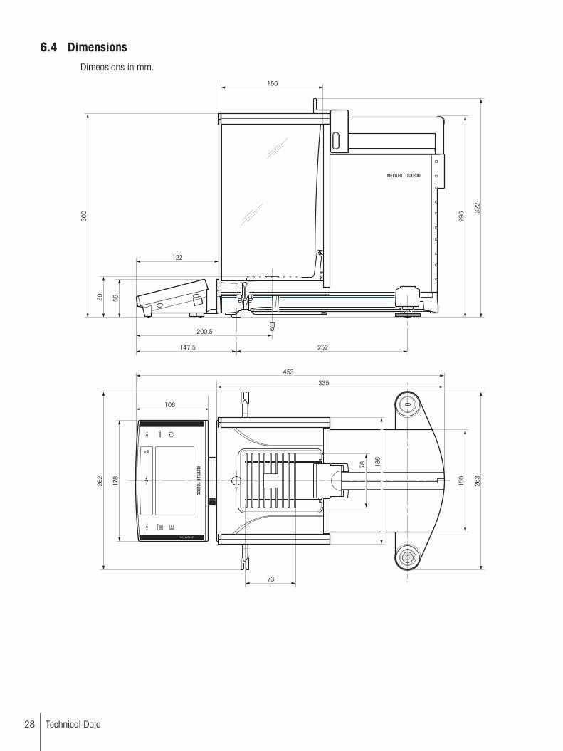
6.4 DimensionsDimensions in mm.
178
5659
300
150
186
78
322
252147.5
200.5
453
73
296
263
122
150
262
106
335
6.5 Interfaces
6.5.1 Specifications of RS232CInterface type: Voltage interface according to EIA RS-232C/DIN 66020 (CCITT V24/V.28)Max. cable length: 15 mSignal level: Outputs:
+5 V ... +15 V (RL = 3 – 7 kΩ)
–5 V ... –15 V (RL = 3 – 7 kΩ)
Inputs:
+3 V ... 25 V
–3 V ... 25 V
Connector: Sub-D, 9-pole, femaleOperating mode: Full duplexTransmission mode: Bit-serial, asynchronousTransmission code: ASCIIBaud rates: 600, 1200, 2400, 4800, 9600, 19200, 384001) (firmware selectable)Bits/parity: 7-bit/even, 7-bit/odd, 7-bit/none, 8-bit/none (firmware selectable)Stop bits: 1 stop bitHandshake: None, XON/XOFF, RTS/CTS (firmware selectable)End-of-line: <CR><LF>, <CR>, <LF> (firmware selectable)
6
15
9
DataGND
Handshake
Pin 2: Balance transmit line (TxD)
Pin 3: Balance receive line (RxD)
Pin 5: Ground signal (GND)
Pin 7: Clear to send (hardware handshake) (CTS)
Pin 8: Request to send (hardware handshake) (RTS)
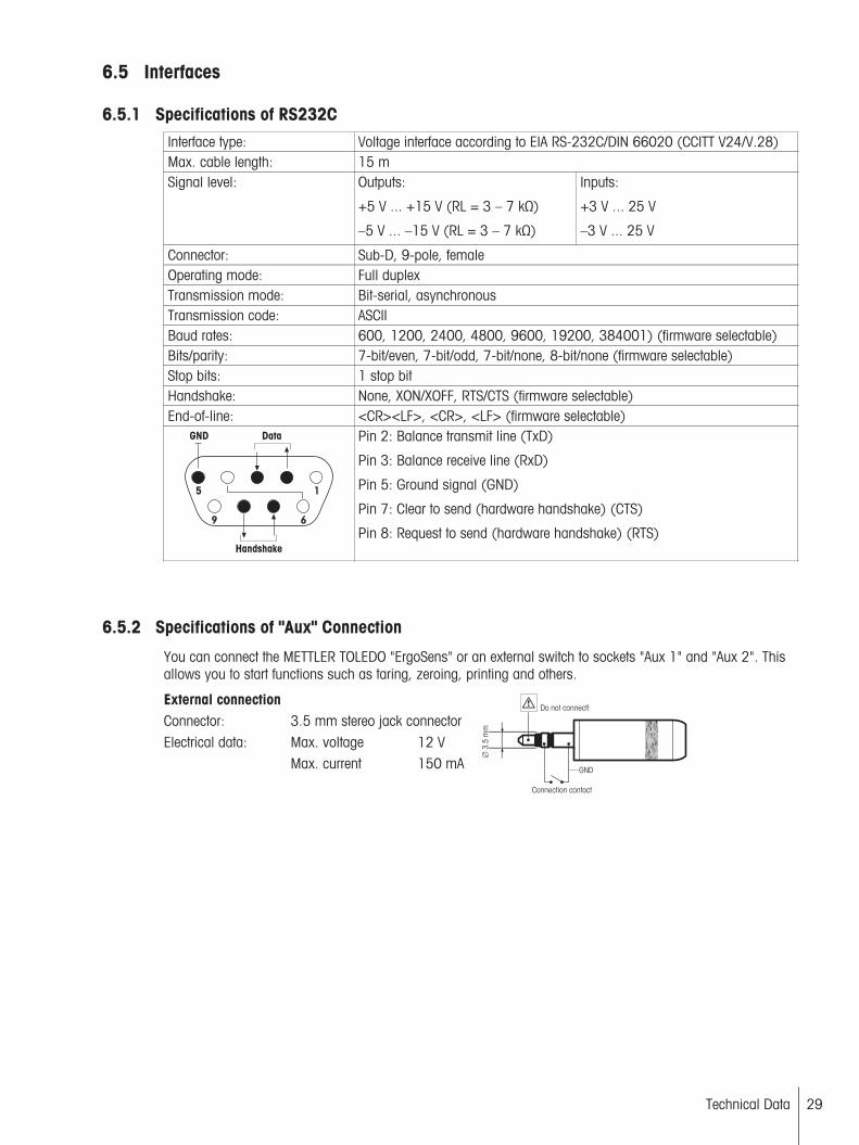
6.5.2 Specifications of "Aux" Connection
You can connect the METTLER TOLEDO "ErgoSens" or an external switch to sockets "Aux 1" and "Aux 2". Thisallows you to start functions such as taring, zeroing, printing and others.
External connection Connector: 3.5 mm stereo jack connectorElectrical data: Max. voltage 12 V
Max. current 150 mA
∅ 3
.5 m
m
GND
Do not connect!
Connection contact
29Technical Data
30 Technical Data
7 Accessories and Spare Parts
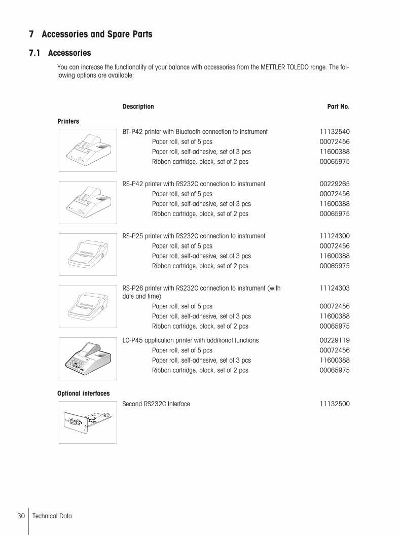
7.1 AccessoriesYou can increase the functionality of your balance with accessories from the METTLER TOLEDO range. The following options are available:
Description Part No.
Printers
BT-P42 printer with Bluetooth connection to instrument 11132540Paper roll, set of 5 pcs 00072456Paper roll, self-adhesive, set of 3 pcs 11600388
Printer
17.375 g
19.319 g
8.003 g
7.773 g
6.554 g
10.506 g
8.097 g
5.876 g
3.205 g
1.098 g
METTLER TOLEDO
Ribbon cartridge, black, set of 2 pcs 00065975
RS-P42 printer with RS232C connection to instrument 00229265Paper roll, set of 5 pcs 00072456Paper roll, self-adhesive, set of 3 pcs 11600388
Printer
17.375 g
19.319 g
8.003 g
7.773 g
6.554 g
10.506 g
8.097 g
5.876 g
3.205 g
1.098 g
METTLER TOLEDO
Ribbon cartridge, black, set of 2 pcs 00065975
RS-P25 printer with RS232C connection to instrument 11124300Paper roll, set of 5 pcs 00072456Paper roll, self-adhesive, set of 3 pcs 11600388Ribbon cartridge, black, set of 2 pcs 00065975
RS-P26 printer with RS232C connection to instrument (withdate and time)
11124303
Paper roll, set of 5 pcs 00072456Paper roll, self-adhesive, set of 3 pcs 11600388Ribbon cartridge, black, set of 2 pcs 00065975
LC-P45 application printer with additional functions 00229119Paper roll, set of 5 pcs 00072456Paper roll, self-adhesive, set of 3 pcs 11600388Menu
Def
Menu
Clear
ID
Code
Result
F
3
2
1
4
5
6
7
8
9
0
LC-P45 Printer
31
1 2 3
METTLER TOLEDO
Ribbon cartridge, black, set of 2 pcs 00065975
Optional interfaces
Second RS232C Interface 11132500
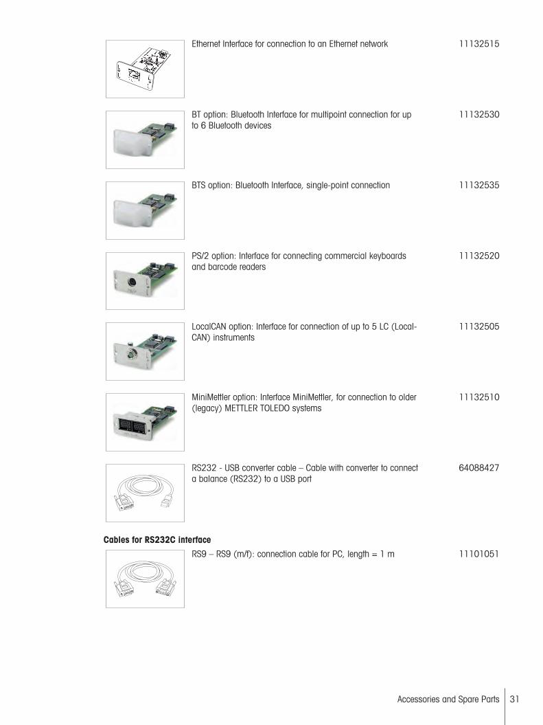
Ethernet Interface for connection to an Ethernet network 11132515
BT option: Bluetooth Interface for multipoint connection for upto 6 Bluetooth devices
11132530
BTS option: Bluetooth Interface, single-point connection 11132535
PS/2 option: Interface for connecting commercial keyboardsand barcode readers
11132520
LocalCAN option: Interface for connection of up to 5 LC (LocalCAN) instruments
11132505
MiniMettler option: Interface MiniMettler, for connection to older(legacy) METTLER TOLEDO systems
11132510
RS232 - USB converter cable – Cable with converter to connecta balance (RS232) to a USB port
64088427
Cables for RS232C interface
RS9 – RS9 (m/f): connection cable for PC, length = 1 m 11101051
31Accessories and Spare Parts

32 Accessories and Spare Parts
RS9 – RS25 (m/f): connection cable for PC, length = 1 m 11101052
Cables for LocalCAN Interface
LC – RS9: Cable for connecting a PC with RS232C, 9-pin (f),lenght = 2 m
00229065
LC – RS25: Cable for connecting a printer or PC with RS232C,25-pin (m/f), lenght = 2 m
00229050
LC – CL: Cable for connecting a device with METTLER TOLEDOCL interface (5-pin), length = 2 m
00229130
LC – LC2: Extension cable for LocalCAN, length = 2 m 00229115
LC – LC5: Extension cable for LocalCAN, length = 5 m 00229116
LC – LCT: Cable branch (T-connector) for LocalCAN 00229118
Cables for MiniMettler Interface
MM – RS9f: RS232C connection cable to MiniMettler interface,length = 1.5 m
00229029

Cables for Terminal
Terminal extension cable, length = 4.5 m 11600517
Cable, one-sided open (2-pin)
Cable between balance and AC adapter, length = 4 m 11132037
Auxiliary displays
BT-BLD Bluetooth auxiliary display for table mounting,168 mm, LCD display with backlighting
11132555
LC/RS-BLD auxiliary display on bench stand, backlit (incl. RScable and separate AC adapter)
00224200
RS/LC-BLDS auxiliary display for table or balance mounting,480 mm, LCD display with backlighting
11132630
Sensors
ErgoSens, optical sensor for hands-free operation 11132601
LC-Switchbox
For connection of up to 3 balances with LocalCAN interface toa printer
00229220
33Accessories and Spare Parts
34 Accessories and Spare Parts
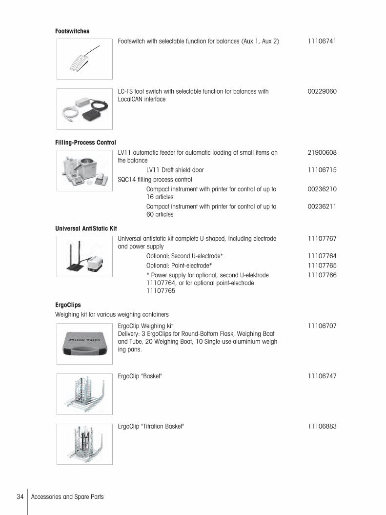
Footswitches
Footswitch with selectable function for balances (Aux 1, Aux 2) 11106741
LC-FS foot switch with selectable function for balances withLocalCAN interface
00229060
Filling-Process Control
LV11 automatic feeder for automatic loading of small items onthe balance
21900608
LV11 Draft shield door 11106715SQC14 filling process control
Compact instrument with printer for control of up to16 articles
00236210
Compact instrument with printer for control of up to60 articles
00236211
Universal AntiStatic Kit
Universal antistatic kit complete U-shaped, including electrodeand power supply
11107767
Optional: Second U-electrode* 11107764Optional: Point-electrode* 11107765* Power supply for optional, second U-elektrode11107764, or for optional point-electrode11107765
11107766
ErgoClipsWeighing kit for various weighing containers
ErgoClip Weighing kitDelivery: 3 ErgoClips for Round-Bottom Flask, Weighing Boatand Tube, 20 Weighing Boat, 10 Single-use aluminium weighing pans.
11106707
ErgoClip "Basket" 11106747
ErgoClip "Titration Basket" 11106883

ErgoClip "Weighing Boat" 11106748
ErgoClip "Round-Bottom Flask" 11106746
ErgoClip "small Flask" 11140180
ErgoClip "Filter holder" 11140185
ErgoClip "Stand" 11140170
ErgoClip "Flask" 11106764
ErgoClip "Tube" 11106784
ErgoClip for Quantos 11141570
35Accessories and Spare Parts

36 Accessories and Spare Parts
ErgoClip Syringe 30008288
ErgoClip Solution Kit 11140251
Single-use aluminium weighing pans, 10 units 11106711
SmardGrid Cover, chromium-nickel steel 11106709
Single-use weighing boats, 500 units 11106712
Grey drip tray 30038741
MinWeigh Door ideal for use with ErgoClip "Flask" 11106749
Density determination
Density kit 11106706
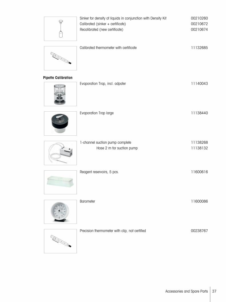
Sinker for density of liquids in conjunction with Density Kit 00210260Calibrated (sinker + certificate) 00210672Recalibrated (new certificate) 00210674
Calibrated thermometer with certificate 11132685
Pipette Calibration
Evaporation Trap, incl. adpater 11140043
Evaporation Trap large 11138440
1-channel suction pump complete 11138268Hose 2 m for suction pump 11138132
Reagent reservoirs, 5 pcs. 11600616
Barometer 11600086
Precision thermometer with clip, not certified 00238767
37Accessories and Spare Parts
38 Accessories and Spare Parts
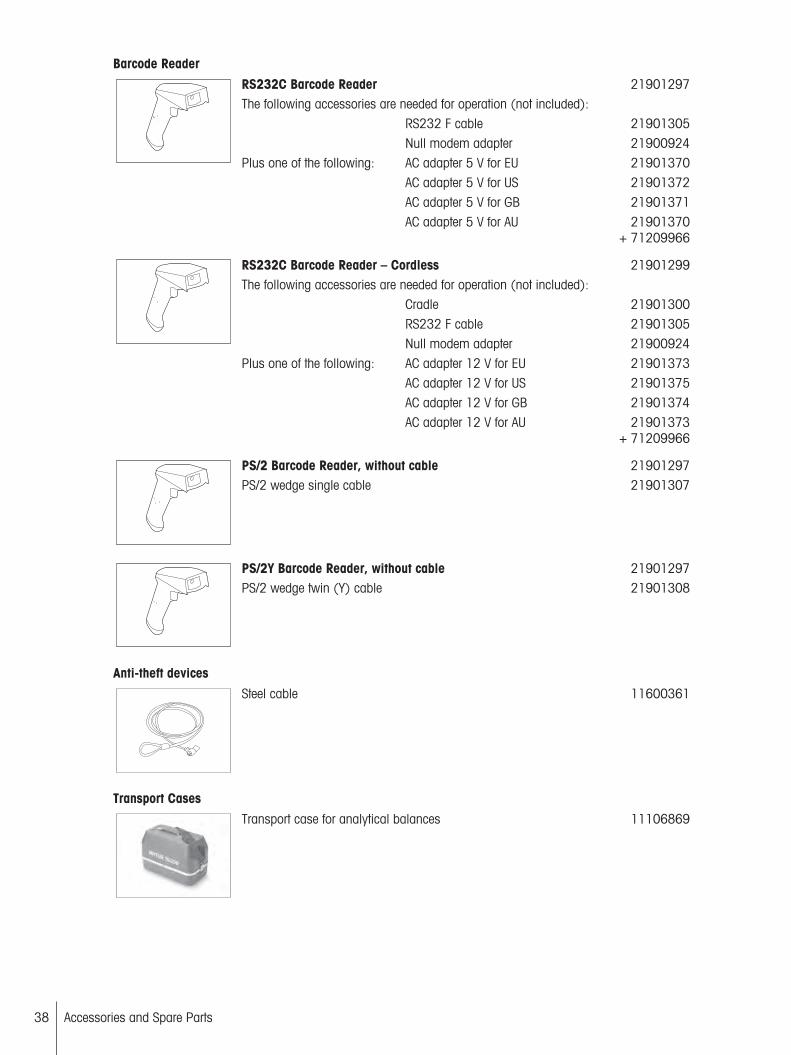
Barcode Reader
RS232C Barcode Reader 21901297The following accessories are needed for operation (not included):
RS232 F cable 21901305Null modem adapter 21900924
Plus one of the following: AC adapter 5 V for EU 21901370AC adapter 5 V for US 21901372AC adapter 5 V for GB 21901371AC adapter 5 V for AU 21901370
+ 71209966
RS232C Barcode Reader – Cordless 21901299The following accessories are needed for operation (not included):
Cradle 21901300RS232 F cable 21901305Null modem adapter 21900924
Plus one of the following: AC adapter 12 V for EU 21901373AC adapter 12 V for US 21901375AC adapter 12 V for GB 21901374AC adapter 12 V for AU 21901373
+ 71209966
PS/2 Barcode Reader, without cable 21901297PS/2 wedge single cable 21901307
PS/2Y Barcode Reader, without cable 21901297PS/2 wedge twin (Y) cable 21901308
Anti-theft devices
Steel cable 11600361
Transport Cases
Transport case for analytical balances 11106869
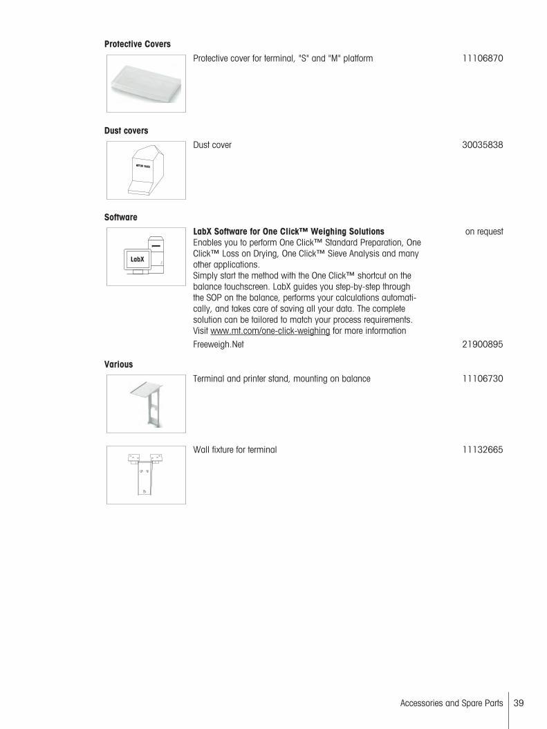
Protective Covers
Protective cover for terminal, "S" and "M" platform 11106870
Dust covers
Dust cover 30035838
Software
LabX Software for One Click™ Weighing SolutionsEnables you to perform One Click™ Standard Preparation, OneClick™ Loss on Drying, One Click™ Sieve Analysis and manyother applications.Simply start the method with the One Click™ shortcut on thebalance touchscreen. LabX guides you step-by-step throughthe SOP on the balance, performs your calculations automatically, and takes care of saving all your data. The completesolution can be tailored to match your process requirements.Visit www.mt.com/one-click-weighing for more information
on request
Freeweigh.Net 21900895
Various
Terminal and printer stand, mounting on balance 11106730
Wall fixture for terminal 11132665
39Accessories and Spare Parts
40 Accessories and Spare Parts
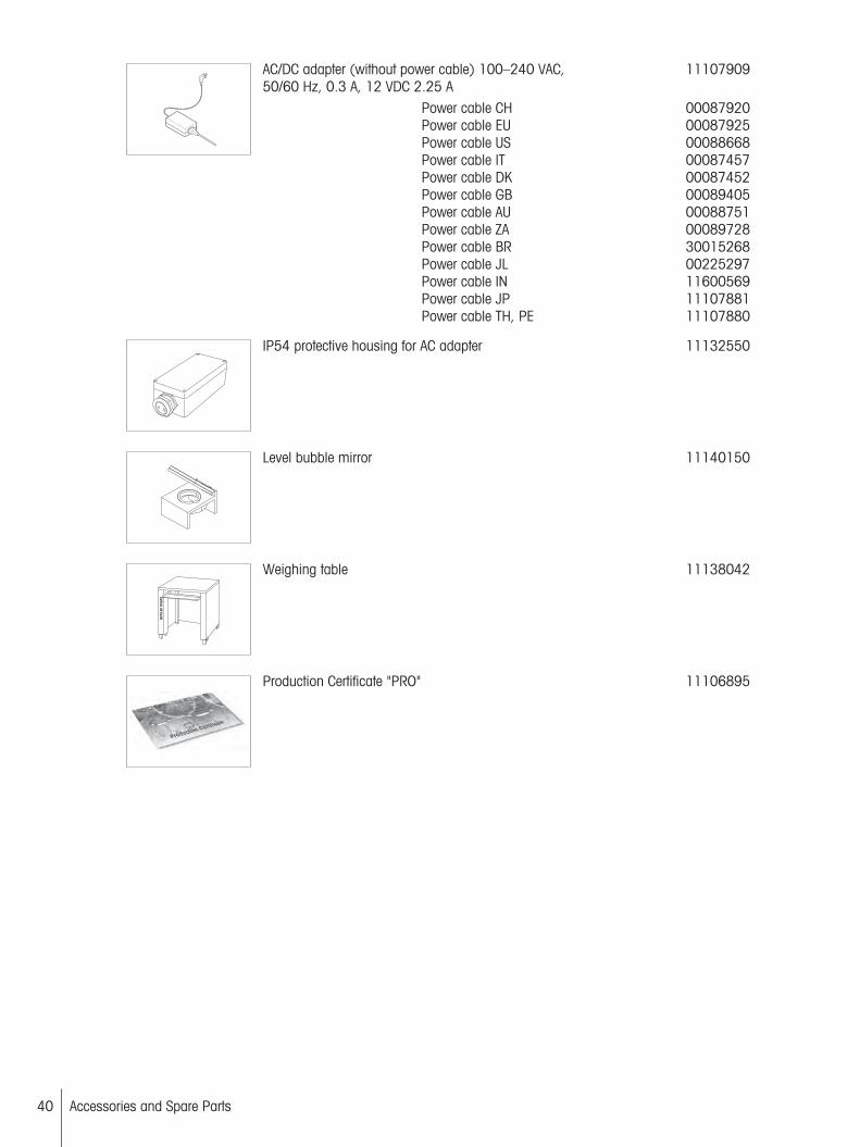
AC/DC adapter (without power cable) 100–240 VAC,50/60 Hz, 0.3 A, 12 VDC 2.25 A
11107909
Power cable CHPower cable EUPower cable USPower cable ITPower cable DKPower cable GBPower cable AUPower cable ZAPower cable BRPower cable JLPower cable INPower cable JPPower cable TH, PE
00087920000879250008866800087457000874520008940500088751000897283001526800225297116005691110788111107880
IP54 protective housing for AC adapter 11132550
Level bubble mirror 11140150
Weighing table 11138042
Production Certificate "PRO" 11106895
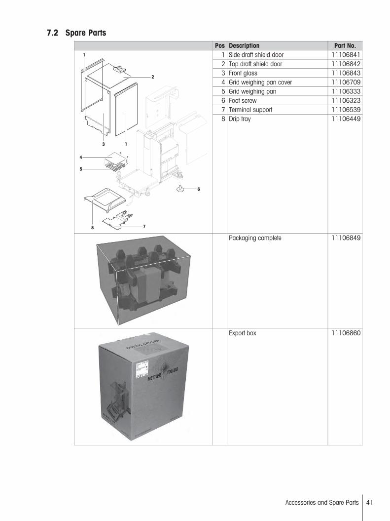
7.2 Spare PartsPos Description Part No.
1 Side draft shield door 111068412 Top draft shield door 111068423 Front glass 111068434 Grid weighing pan cover 111067095 Grid weighing pan 111063336 Foot screw 111063237 Terminal support 11106539
1
1
3
8
6
4
5
7
2
8 Drip tray 11106449
Packaging complete 11106849
Export box 11106860
41Accessories and Spare Parts

42 Accessories and Spare Parts
8 Appendix
8.1 MT-SICS Interface Commands and FunctionsMany of the instruments and balances used have to be capable of integration in a complex computer or dataacquisition system.
To enable you to integrate balances in your system in a simple manner and utilize their capabilities to the full,most balance functions are also available as appropriate commands via the data interface.
All new METTLER TOLEDO balances launched on the market support the standardized command set "METTLERTOLEDO Standard Interface Command Set" (MT-SICS). The commands available depending on the functionalityof the balance.
For further information please refer to the Reference Manual MT-SICS downloadable from the Internet under
u www.mt.com/xs-analytical
8.2 Procedure for Certified Balances
PrefaceCertified balances are subject to the national, legal requirements of "non-automatic balances".
Switching on the balance Switching on
• Immediately after being switched on, the balance displays 0.000.. g.• The balance is always started up with the "Factory setting" unit.
Switch-on range• At maximum 20% of the type load, otherwise overload is displayed (OIML R76 4.5.1).
Stored value as switch-on zero point• It is not permissible to use a stored value as a switch-on zero point; the MT-SICS M35 command is not
available (OIML R76 T.5.2).
Display Display of the weight value
• The "e" certification value is always shown in the display and is specified at the model designation plate(OIML R76 T.3.2.3 and 7.1.4).
• If the display increment is lower than the "e" certification value, this is variably displayed for the net, grossand weighed tare. (Graying of the digits or certification brackets) (OIML R76 T.2.5.4 and 3.4.1).
In accordance with guidelines, the tested display increment (certification value) is never lower than 1 mg(OIML R76 T.3.4.2).
At balances with d = 0.1 mg, the digits below 1 mg are displayed in gray. These digits in brackets areprinted. In accordance with legal metrology requirements, this illustration does not affect the accuracy of theweighing results.
Units of measurement• The display and info unit are firmly set to g or mg (depending on the model).• The following applies for the "Custom unit":
– No certification brackets.– The following names are blocked, this applies to upper and lower case letters.
– All official units (g, kg, ct etc.).– c, ca, car, cm, crt, cart, kt, gr, gra, gram, grm, k, kilo, to, ton.– All names with "o" which can be replaced by a zero (0z, 0zt etc.).
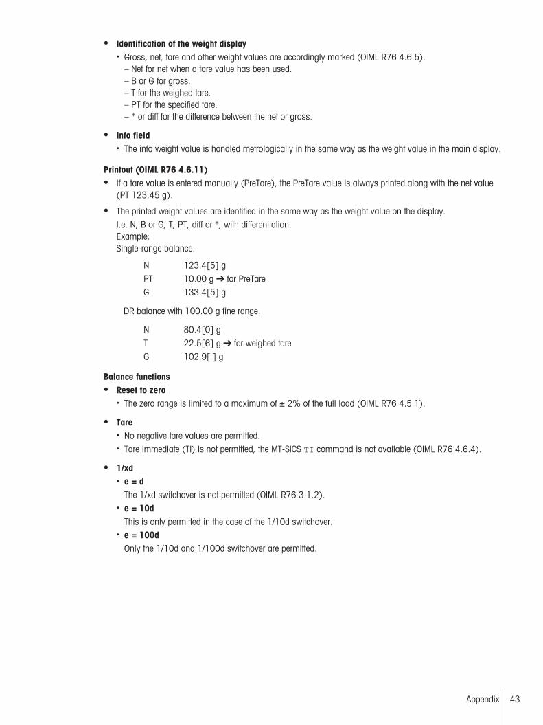
Identification of the weight display• Gross, net, tare and other weight values are accordingly marked (OIML R76 4.6.5).
– Net for net when a tare value has been used.– B or G for gross.– T for the weighed tare.– PT for the specified tare.– * or diff for the difference between the net or gross.
Info field• The info weight value is handled metrologically in the same way as the weight value in the main display.
Printout (OIML R76 4.6.11) If a tare value is entered manually (PreTare), the PreTare value is always printed along with the net value
(PT 123.45 g).
The printed weight values are identified in the same way as the weight value on the display. I.e. N, B or G, T, PT, diff or *, with differentiation.Example:Single-range balance.
N 123.4[5] gPT 10.00 g for PreTareG 133.4[5] g
DR balance with 100.00 g fine range.
N 80.4[0] gT 22.5[6] g for weighed tareG 102.9[ ] g
Balance functions Reset to zero
• The zero range is limited to a maximum of ± 2% of the full load (OIML R76 4.5.1).
Tare• No negative tare values are permitted.• Tare immediate (TI) is not permitted, the MT-SICS TI command is not available (OIML R76 4.6.4).
1/xd• e = d
The 1/xd switchover is not permitted (OIML R76 3.1.2).• e = 10d
This is only permitted in the case of the 1/10d switchover.• e = 100d
Only the 1/10d and 1/100d switchover are permitted.
43Appendix
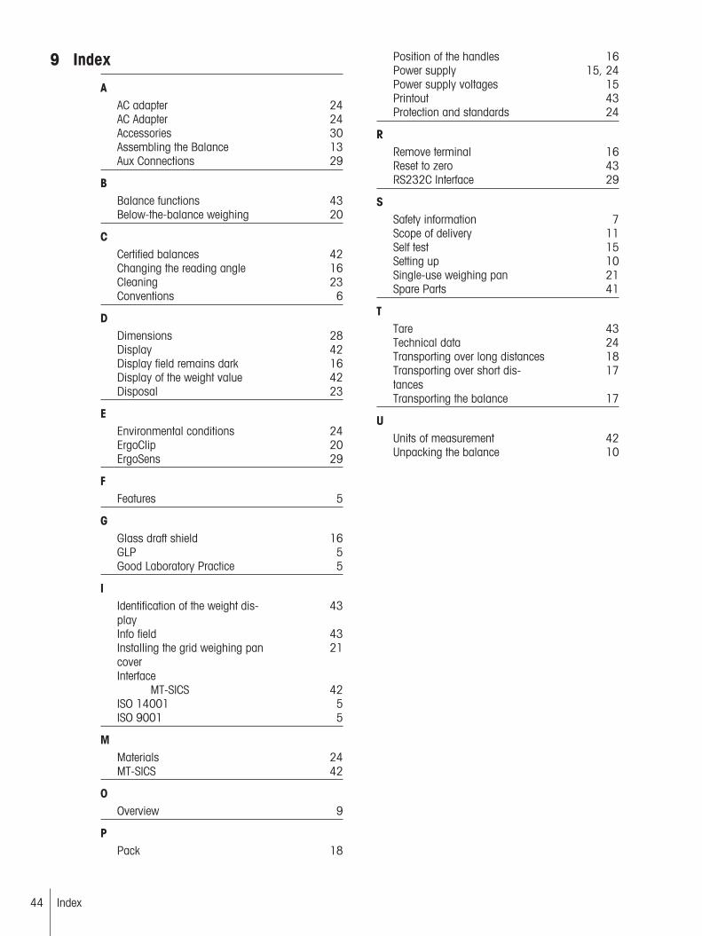
9 Index
AAC adapter 24AC Adapter 24Accessories 30Assembling the Balance 13Aux Connections 29
BBalance functions 43Below-the-balance weighing 20
CCertified balances 42Changing the reading angle 16Cleaning 23Conventions 6
DDimensions 28Display 42Display field remains dark 16Display of the weight value 42Disposal 23
EEnvironmental conditions 24ErgoClip 20ErgoSens 29
FFeatures 5
GGlass draft shield 16GLP 5Good Laboratory Practice 5
IIdentification of the weight display
43
Info field 43Installing the grid weighing pancover
21
InterfaceMT-SICS 42
ISO 14001 5ISO 9001 5
MMaterials 24MT-SICS 42
OOverview 9
PPack 18
Position of the handles 16Power supply 15, 24Power supply voltages 15Printout 43Protection and standards 24
RRemove terminal 16Reset to zero 43RS232C Interface 29
SSafety information 7Scope of delivery 11Self test 15Setting up 10Single-use weighing pan 21Spare Parts 41
TTare 43Technical data 24Transporting over long distances 18Transporting over short distances
17
Transporting the balance 17
UUnits of measurement 42Unpacking the balance 10
Index44

Mettler-Toledo AG, Laboratory & Weighing TechnologiesCH-8606 Greifensee, SwitzerlandTel. +41 (0)44 944 22 11Fax +41 (0)44 944 30 60www.mt.com
Subject to technical changes.© Mettler-Toledo AG 05/201211781099A en
www.mt.com/excellenceFor more information
*11781099*