operating instructions en brugsanvisning da bruksanvisning ...€¦ · pd40 operating instructions...
TRANSCRIPT
PD 40Operating instructions en
Brugsanvisning da
Bruksanvisning sv
Bruksanvisning no
Käyttöohje fi
Инструкция по зксплуатации ru
Lietoßanas pamåcîba lv
Instrukcija lt
Kasutusjuhend et

1 2
6
+#34+“+±+≠
+Ç+[
5798
1

2 1
34
56
2
1
2
3
1
4 5
6 7

PD 40 laser range meter
It is essential that the operating instructionsare read before the tool is operated for thefirst time.
Always keep these operating instructionstogether with the tool.
Ensure that the operating instructions arewith the tool when it is given to otherpersons.
Contents Page1. General information 172. Description 183. Insert tools, accessories 224. Technical data 225. Safety rules 236. Before use 247. Operation 288. Care and maintenance 309. Troubleshooting 31
10. Disposal 3211. Manufacturer’s warranty tools 3212. EC declaration of conformity 33
1 These numbers refer to the corresponding illustra-tions. The illustrations can be found on the fold outcover pages. Keep these pages open while studyingthe operating instructions.In these operating instructions, the designation “thetool” always refers to the PD 40 laser range meter.
Parts, operating controls and indicators 1
@ On/off button; Side measure button= Graphic display% Measure button& Delete (clear) button( Horizontal bubble) Area button+ Folding spike§ / " thread for PDA 71 measuring extension/ Rear contact points: Minus button· Plus button$ Reference button£ Laser exit lens| Receiving lens
1. General information1.1 Safety notices and their meaning
DANGERDraws attention to imminent danger that could leadto serious bodily injury or fatality.
WARNINGDraws attention to a potentially dangerous situationthat could lead to serious personal injury or fatality.
CAUTIONDraws attention to a potentially dangerous situationthat could lead to slight personal injury or damage tothe equipment or other property.
NOTEDraws attention to an instruction or other usefulinformation.
1.2 Explanation of the pictograms and otherinformation
Warning signs
Generalwarning
en
17
>1/4s
Serial number
LASER RADIATION - DO NOTSTARE INTO BEAM
620-690nm/0.95mW max.CLASS II LASER PRODUCT
Hilti = trademark of Hilti Corp., Schaan, LI Made in Germany
PD 40
AVOID EXPOSURELaser radiation is emitted from this aperture
Manufactured:
This device complies with part 15 of the FCC Rules. (1) This device may not cause harmful interference, and (2) this device must accept any inter-ference received, including inter-ference that may cause undesired operation.
Item No.: 30399 Power: 3V nom/400 mA
DIN EN 60825-1:2003
01
Symbols
Read theoperating
instructionsbefore use.
Return wastematerial forrecycling.
Laser class II accordingto CFR 21, § 1040 (FDA)
Laser class 2in accordance
withEN 60825
1:2003
Do not lookinto the beam.
Temperatureindicator
Battery statusindicator
Hardwareerrors
Unfavorableoperatingconditions
Type identification plate
PD 40
Location of identification data on the toolThe type designation and serial number can be foundon the type identification plate on the tool. Make anote of this data in your operating instructions andalways refer to it when making an enquiry to yourHilti representative or service department.
Type:
Serial no.:
2. Description2.1 Use of the product as directed
The tool is designed for measuring distances, calculating areas and adding or subtracting distances.Do not use the tool as a leveling tool.Measurements taken from plastic foam materials such as polystyrene foam, from snow or from highly reflectivesurfaces (mirrors, glass, etc.) may produce inaccurate results.The tool and its ancillary equipment may present hazards when used incorrectly by untrained personnel orwhen used not as directed.
en
18
Take the influences of the surrounding area into account. Do not use the appliance where there is a risk of fireor explosion.Observe the information printed in the operating instructions concerning operation, care and maintenance.To avoid the risk of injury, use only genuine Hilti accessories and additional equipment.Modification of the tool is not permissible.
NOTEObserve the permissible operating and storage temperatures.
2.2 DisplayThe measurements, settings and tool status are shown in the display. When the tool is in measuring mode,the measurements taken are shown at the bottom of the display area (the result line). When using a function,e.g. area measurement, the distances measured are shown in the intermediate result line and the calculatedresult is shown at the bottom of the display (the result line).
2.3 Display illuminationIn low light conditions, the display is illuminated automatically as soon as a button is pressed. The displayillumination intensity is reduced to 50% after 10 seconds. If no button is pressed over a period of 20 seconds,the display illumination switches off automatically.
NOTEIllumination of the display consumes battery power. Shorter battery life is therefore to be expected when thisfeature is used frequently.
2.4 Basic principleThe distance is measured along a laser beam emitted by the tool to the point at which the beam strikesa reflective surface. The target from which the measurement is taken is clearly identified by the red lasermeasuring spot. The range of the tool depends on the reflectance and structure of the target surface fromwhich measurements are taken.
2.5 Measuring principleThe tool emits a visible laser beam carrying signal pulses which are reflected by the target. The time betweenreflected pulses is used as a basis for determining the distance.This measuring principle permits highly accurate and reliable measurement of distances to objects withoutneed for special reflectors.
2.6 Standard measuring display modeStandard measuring display mode is always activated when the “On/off” or “Measure” button is pressed toswitch the tool on.
en
19
2.7 Symbols in the display
Temperature Temperature too high(>+50°C) / too low (<10°C).
Allow the tool to cool down or warm up.
Unfavorable operatingconditions
Insufficient reflectedlaser light.
Observe the minimum measuring distance (50 mmfrom the front edge of the tool); clean the lenses;take measurements from a different surface or use atarget plate.
General hardware error Switch the tool off and on again. If the fault persists,please contact Hilti Service.
2.8 Control panel
Measure button Activates the laser beam.Begins distance measurement.Activates continuous measuring mode (long press,approx. 2 sec.).Stops continuous measuring mode.
Plus button Activates distance and area addition.Distances shown in the standard measuring displayare added.Adds areas when in area measuring mode.
Minus button Activates distance and area subtraction.Distances shown in the standard measuring displayare subtracted.Subtracts areas when in area measuring mode.
Area button Activates area measuring mode.When measurements have been taken: Deletes allmeasurements and restarts the function.When no measurements have been taken: ends areameasuring mode.Stops continuous measuring (tracking).
Delete (clear) button The C button has variousfunctions depending onoperating mode.
Stops continuous measuring (tracking).
Clears the standard measuring display.Clears the last measurement and returns to“Functions”.Ends area measuring mode if no measurementshave been taken.
On/off button When the tool is switched off, press the buttonbriefly to switch it on.When the tool is switched off, press and hold thebutton to activate the menu.When the tool is switched on, press the buttonbriefly to switch it off.
Reference button Switches the various measuring references betweenfront and rear.
en
20
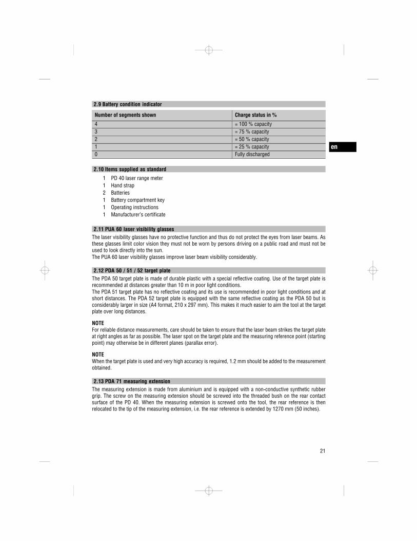
2.9 Battery condition indicator
Number of segments shown Charge status in %
4 = 100 % capacity3 = 75 % capacity2 = 50 % capacity1 = 25 % capacity0 Fully discharged
2.10 Items supplied as standard
1 PD 40 laser range meter1 Hand strap2 Batteries1 Battery compartment key1 Operating instructions1 Manufacturer’s certificate
2.11 PUA 60 laser visibility glassesThe laser visibility glasses have no protective function and thus do not protect the eyes from laser beams. Asthese glasses limit color vision they must not be worn by persons driving on a public road and must not beused to look directly into the sun.The PUA 60 laser visibility glasses improve laser beam visibility considerably.
2.12 PDA 50 / 51 / 52 target plateThe PDA 50 target plate is made of durable plastic with a special reflective coating. Use of the target plate isrecommended at distances greater than 10 m in poor light conditions.The PDA 51 target plate has no reflective coating and its use is recommended in poor light conditions and atshort distances. The PDA 52 target plate is equipped with the same reflective coating as the PDA 50 but isconsiderably larger in size (A4 format, 210 x 297 mm). This makes it much easier to aim the tool at the targetplate over long distances.
NOTEFor reliable distance measurements, care should be taken to ensure that the laser beam strikes the target plateat right angles as far as possible. The laser spot on the target plate and the measuring reference point (startingpoint) may otherwise be in different planes (parallax error).
NOTEWhen the target plate is used and very high accuracy is required, 1.2 mm should be added to the measurementobtained.
2.13 PDA 71 measuring extensionThe measuring extension is made from aluminium and is equipped with a non conductive synthetic rubbergrip. The screw on the measuring extension should be screwed into the threaded bush on the rear contactsurface of the PD 40. When the measuring extension is screwed onto the tool, the rear reference is thenrelocated to the tip of the measuring extension, i.e. the rear reference is extended by 1270 mm (50 inches).
en
21

3. Insert tools, accessoriesTarget plate PDA 50Target plate PDA 51Target plate PDA 52Measuring extension PDA 71
Hand strap PDA 60Soft pouch PDA 65Laser visibility glasses PUA 60
4. Technical dataRight of technical changes reserved.
Technical data Values
Power supply 3V DC AA size batteriesBattery condition check Battery condition indicator with 4 segments showing
100%, 75%, 50%, 25% charge : No segmentsshown: The batteries are exhausted
Measuring range 0.05…200 mTypical measuring range without target plate Drywall panel, white: 100 m
Concrete, dry: 70 mBrick, dry: 50 m
Accuracy Typically ±1.0 mm for single and continuousmeasurement
Smallest unit displayed 1 mmBeam diameter Beam length 10 m: Max. 6 mm
Beam length 50 m: Max. 30 mmBeam length 100 m: Max. 60 mm
Basic operating modes Single measuring, continuous measuring, calcula-tion/functions
Display Illuminated dot matrix display with permanentindication of operating mode and battery condition
Laser Visible 635 nm, Output power less than 1 mW: Laserclass 2IEC 825 1:2003CFR 21 § 1040 (FDA)
Automatic cut out Laser: 1 minTool: 10 min
Battery life Max. number of measurements with laserbeam switched on for a time of 10 s Al-kaline 8,000…10,000 NiMH 6,000…8,000
Operating temperature range -10…+50°CStorage temperature -30…+70°CProtection class (except battery compartment) IP 54 protection against dust and water jets
IEC 529
en
22
Technical data Values
Weight without batteries 170 gDimensions 120 mm x 55 mm x 28 mm
Menu / units Distance Area Volumem Meters m mcm Centimeters m mmm Millimeters m mIn Inches, decimal Inches InchesIn / / inch Inches InchesIn / / inch Inches InchesIn / / inch Inches InchesFt Feet, decimal Feet FeetFt / Feet inches / Feet FeetFt / Feet inches / Feet FeetFt / Feet inches / Feet FeetYd Yards, decimal Yards Yards
5. Safety rulesIn addition to the information relevant to safetygiven in each of the sections of these operatinginstructions, the following points must be strictlyobserved at all times.
5.1 Basic information concerning safetya) Do not render safety devices ineffective and do
not remove information and warning notices.b) Keep laser tools out of reach of children.c) Failure to follow the correct procedures when
opening the tool may cause emission of laserradiation in excess of class 2. Have the toolrepaired only at a Hilti service center.
d) Check that the tool functions correctly each timebefore use.
e) Operation of the tool in the proximity of pregnantwomen is not permissible.
f) Measurements taken from surfaces with low re-flectivity in highly reflective surroundings may beinaccurate.
g) Measurements taken through panes of glass orother objects may be inaccurate.
h) Rapid changes in the conditions under whichthe measurement is taken, e.g. persons walkingthrough the laser beam, may lead to inaccurateresults.
i) Do not point the tool toward the sun or otherpowerful light sources.
5.2 Proper organization of the workplacea) Avoid unfavorable body positions when working
on ladders or scaffolding. Make sure you workfrom a safe stance and stay in balance at alltimes.
b) Check the measuring reference setting beforetaking the measurement.
c) When the tool is brought into a warm environ-ment from very cold conditions, or vice versa,allow it to become acclimatized before use.
d) As a precaution, check the previous settings andadjustments you have made.
e) When setting up the tool with the aid of thebubble level, view the bubble level at a slightangle.
f) Secure the area in which you are working andtake care to avoid directing the beam towardsother persons or towards yourself when settingup the tool.
g) Use the tool only within its specified limits.h) Observe the accident prevention regulations ap-
plicable in your country.
en
23
5.3 Electromagnetic compatibilityAlthough the tool complies with the strict require-ments of the applicable directives, Hilti cannot en-tirely rule out the possibility of the tool being subjectto interference caused by powerful electromagneticradiation, leading to incorrect operation. Check theaccuracy of the tool by taking measurements by othermeans when working under such conditions or if youare unsure. Likewise, Hilti cannot rule out the pos-sibility of interference with other devices (e.g. aircraftnavigation equipment). The tool complies with therequirements of class A; The possibility of interfer-ence occurring in a domestic environment cannot beexcluded.
5.4 General safety rulesa) Check the condition of the tool before use. If the
tool is found to be damaged, have it repaired ata Hilti service center.
b) The user must check the accuracy of the toolafter it has been dropped or subjected to othermechanical stresses.
c) Although the tool is designed for the tough con-ditions of jobsite use, as with other measuringinstruments it should be treated with care.
d) Although the tool is protected to prevent entryof dampness, it should be wiped dry each timebefore being put away in its transport container.
5.5 Electricala) Keep the batteries out of reach of children.b) Do not allow the batteries to overheat and do not
expose them to fire. The batteries may explode orrelease toxic substances.
c) Do not charge the batteries.d) Do not solder the batteries into the tool.e) Do not discharge the batteries by short circuit-
ing. This may cause them to overheat and presenta risk of personal injury (burns).
f) Do not attempt to open the batteries and do notsubject them to excessive mechanical stress.
5.6 Laser classificationDepending on the version purchased, the tool com-plies with Laser Class 2 in accordance with IEC8251:2003 / EN60825 1:2003 and Class II in accordancewith CFR 21 § 1040 (FDA). This tool may be usedwithout need for further protective measures. Theeyelid closure reflex protects the eyes when a per-son looks into the beam unintentionally for a briefmoment. This eyelid closure reflex, however, may benegatively affected by medicines, alcohol or drugs.Nevertheless, as with the sun, one should not lookdirectly into sources of bright light. Do not direct thelaser beam toward persons.
5.7 TransportAlways remove the batteries before shipping thetool.
6. Before use
6.1 Inserting the batteries 2
CAUTIONDo not use damaged batteries.
CAUTIONAlways replace the complete set of batteries.
DANGERDo not mix old and new batteries. Do not mixbatteries of different makes or types.
1. Unscrew the battery compartment cover from therear of the tool.
2. Remove the batteries from the packaging andinsert them in the tool.NOTE Take care to observe correct polarity (seesymbols in battery compartment).
3. Check to ensure that the battery compartmentcover is closed securely.
6.2 Switching the tool on / off1. The tool can be switched on by pressing either
the “On / off” button or the “Measure” button.
en
24

m
MENU
2. When the tool is switched off, press the “On / off”button: The tool switches on.The laser beam is switched off.
3. When the tool is switched on, press the “On / off”button: The tool switches off.
4. When the tool is switched off, press the “Measure”button: The tool and the laser beam switch on.
6.3 First distance measurements1. Press the “Measure” button once.
If switched off, the tool will be switched on andthe laser beam activated.If the tool is already switched on, the laser beamwill be activated.
2. Aim the tool by positioning the visible laser spoton a white surface at a distance of approx. 3 10m.
3. Press the “Measure” button again.The distance will be displayed in less than asecond, e.g. 5.489 m.You have just taken your first measurement withthe tool.
6.4 Settings menu
1. With the tool switched off, press the “On / off”button for approx. 2 seconds to enter menu mode.
2. Press the “Plus” button to switch the beep signalon or off.
3. Press the “Minus” button repeatedly to scrollthrough the choice of units.
4. Press the “On / off” button briefly to close themenu.The tool is switched off and all the settings shownwill be saved.
6.5 Measuring referencesNOTEThe tool can take measurements from 4 differentreference (contact) points. The “Reference” buttonon the left on the front of the tool is used to switchbetween the front and rear references (front or rearedge of the tool). The reference is set automaticallyto the tip of the spike when the spike is foldedout through 180°. When the measuring extension isscrewed into place, this is detected automatically bythe tool and indicated by the long extension symbolin the display.
Front edge
Rear edge
Spike
PDA 71 measuring extension: is detected automatic-ally when screwed in.
6.6 Measuring distancesNOTEWhen the spike is folded back in, the measuringreference is always reset to the rear edge of the toolirrespective of how far the spike was folded out or towhich point on the tool the measuring reference waspreviously set.
en
25

---------- m
---------- m
5.489 m
m27.317
5.489 m
m
m12.349
24.634
Distances can be measured from all stationary targetswithout a highly reflective surface, i.e. concrete, stone,wood, plastic, paper, etc. The use of prisms or otherhighly reflective targets is not permissible and, ifattempted, may falsify the results.6.6.1 Measuring distances step by step
NOTEThe range meter measures distances in a very shorttime and simultaneously shows various informationin the display.
Switch the tool on by pressing the “On / off” button.
Press the “Measure” button once. The laser beam isswitched on and is visible in the form of a spot on thetarget surface. This aiming mode is indicated in thedisplay by a blinking laser symbol.
Aim at the target. Press the “Measure” button onceagain to measure the distance. The result usuallyappears in the result line in less than a second andthe laser beam then switches off.
If further measurements are taken, up to three previ-ously determined distances are shown in the interme-diate result lines, i.e. a total of the last four measureddistances are shown.
The tool can, of course, be switched on again at anytime by pressing the “Measure” button. Pressing theC button clears all currently displayed values.
6.6.2 Measuring modesDistances can be measured using two different meas-uring modes, i.e. single distance measuring or con-tinuous measuring. Continuous measuring mode isused for setting out given distances or lengths andcan also be used where distance measurement isotherwise difficult, e.g. at corners, edges or in niches,etc.
en
26
6.6.2.1 Single distance measuring (“Measure”button)
1. Switch the laser beam on by pressing the “Meas-ure” button.
2. Press the “Measure” button again.The measured distance will be shown in the resultline at the bottom of the display in less than asecond.
6.6.2.2 Single distance measuring (“On /off”button)
1. Switch the laser beam on by pressing the “On /off” button.
2. Press the “Measure” button to switch the laserbeam on and then aim the tool at the target.
3. Press the “Measure” button again.The measured distance will be shown in the resultline at the bottom of the display in less than asecond.
6.6.2.3 Continuous measuring (tracking)NOTEContinuous measuring is possible in all situationswhere individual distances can be measured. Thisapplies also to functions, such as areas.
1. Press the “Measure” button for about 2 secondsto activate the continuous measuring mode.NOTE When doing so, it doesn’t matter whetherthe tool or the laser beam is switched on oroff. The tool will always switch to continuousmeasuring mode.During continuous measuring, distances are up-dated in the result line at the rate of approx. 610 measurements every second. The measuringrate depends on reflectivity of the target surface.If the beep signal is active, continuous measuringis indicated by a beep signal approx. 2 3 timesper second.
2. Measuring is stopped by pressing the “Measure”button once again.The last valid measurement is then shown in theresult line in the display.
6.6.3 Measuring from corners 3 4
The spike is used when measuring diagonally acrossrooms or from inaccessible corners.
1. Fold out the spike through 180°.The measuring reference is then set automaticallyto the end of the spike. The range meter takesthe extended reference point into account andcorrects the measured distances accordingly.
2. Position the range meter with the spike at thedesired starting point for the measurement andaim toward the target.
3. Press the “Measure” button.The measured distance is shown in the display.
6.6.4 Measuring with the aid of targetobjects 5 6
When taking measurements to outside corners (e.g.on outside walls of buildings, perimeter fences, etc.),boards, bricks or other suitable objects can be heldagainst the corner and used as the target. Use ofthe PDA 50, PDA 51 or PDA 52 target plate isrecommended for long distances and in unfavorablelight conditions, e.g. in strong sunlight.
6.6.5 Measuring in bright conditionsWe recommend use of the PDA 50, PDA 51 or PDA 52target plate for long distances and in very bright lightconditions.
6.6.6 Taking measurements to rough surfaces 7
When measuring to rough surfaces, e.g. rough plasteretc., an average distance value is measured with thecenter of the laser spot weighted higher than theedges of the laser spot.
6.6.7 Taking measurements to curved orinclined surfaces
If the laser beam strikes the target surface at a verynarrow angle, the light reflected may be inadequate.Conversely, too much light may be reflected towardthe tool in situations where the laser beam strikesthe target perpendicularly. We recommend use of thePDA 50, PDA 51 or PDA 52 target plate in both ofthese situations.
6.6.8 Taking measurements to wet or shinysurfaces
As long as the range meter can be aimed directly atthe surface, the distance to the target will be reliablymeasured. With highly reflective surfaces, a reduction
en
27

17.838
m
m12.349
+ 5.489
m
in range must be expected and the distance to theactual point of reflection may be measured.
6.6.9 Taking measurements to transparentsurfaces
It is generally possible to measure distances to trans-parent or semi transparent materials, e.g. liquids,polystyrene foam, etc. Light penetrates these mater-ials, however, and measuring errors may thereforeoccur. Measuring errors may also occur when meas-urements are taken through glass or if objects arepresent within the line of the laser beam.
6.6.10 Measuring range
6.6.10.1 Increased rangeThe range of the tool is generally increased whenmeasurements are taken in the dark, at dawn or dusk
and when the target and/or the tool is shaded frombright light.Use of the PDA 50, PDA 51 or PDA 52 target platealso increases the range of the tool.
6.6.10.2 Reduced measuring rangeMeasuring range may be reduced in bright conditions,e.g. in bright sunlight or when working under verypowerful floodlights.The range of the tool may be reduced when meas-urements are taken through glass or when objects liewithin the path of the laser beam.The range of the tool may be reduced when measure-ments are taken to mat green, blue or black surfacesor to wet or shiny surfaces.
7. Operation
7.1 Distance measurementsNOTEWith all functions of the tool, each step in the opera-tion is always indicated in the display.
NOTEContinuous measuring mode can be used with allfunctions in which individual distance measurementis possible.
NOTEIf measuring errors occur during continuous meas-uring, and continuous measuring mode is canceledby pressing the “Measure” button again, the last validmeasurement will be displayed.
7.2 Adding distances
Individual distances can be conveniently added. Thisis useful, for example, for determining the total lengthof the inner face of door or window openings or
en
28
0.625
m
m3.947
- 3.322
mm67.784
5.489 m
m12.349
3m67.784
5.489 m
m12.349
2
for adding several individual distances that form aperimeter.1. Press the “Measure” button (the laser beam will
switch on).2. Aim the range meter at the target.3. Press the “Measure” button.
The first distance will be measured and displayed(the laser then switches off).
4. Press the “Plus” button. The first distance is thendisplayed in the middle result line and a plus signappears in the lower (intermediate) result line (thelaser beam switches on).
5. Aim the range meter at the target.6. Press the “Measure” button.
The second distance is then measured and dis-played in the lower (intermediate) result line. Theresult of the addition is shown in the result line.The current total of the distances is always shownin the result line.The procedure can be repeated until all distanceshave been added.
7. To terminate the addition of distances, simplymeasure a distance without first pressing the“Plus” button.All previous measuring and calculation results areshown in the intermediate results lines.
8. Press the C button to clear the display.
7.3 Subtracting distances
Individual distances can be conveniently subtractedfrom each other, e.g. in order to determine the dis-tance between the underside of a pipe and the ceiling.This can be done by subtracting the distance betweenthe floor and the underside of the pipe from thedistance between the floor and the ceiling. If thepipe diameter is subtracted, the result is the distancebetween the top of the pipe and the ceiling.
1. Press the “Measure” button (the laser beamswitches on).
2. Aim the range meter at the target.3. Press the “Measure” button. The first distance
will be measured and displayed (the laser thenswitches off).
4. Press the “Minus” button. The first distance isthen displayed in the middle result line and aminus sign appears in the lower (intermediate)result line (the laser beam switches on).
5. Aim the range meter at the target.6. Press the “Measure” button.
The second distance is then measured and dis-played in the lower (intermediate) result line.The result of the subtraction is shown in the resultline.The current difference in distance is always shownin the result line.The procedure can be repeated until all distanceshave been subtracted.
7. To terminate the subtraction of distances, simplymeasure a distance without first pressing the“Minus” button.All previous measuring and calculation results areshown in the intermediate results lines.
8. Press the C button to clear the display.
7.4 Measuring areas
Each step of the area measurement operation isindicated graphically in the display. For example,to determine the floor area of a room, proceed asfollows:1. Press the “Area” button to activate area measuring
mode.NOTE When the area function is activated, thelaser beam is already switched on.
en
29
2. Aim the range meter at the target.3. Press the “Measure” button.
For example, to determine the floor area of aroom, proceed as follows:.The graphic display automatically prompts you tomeasure the length of the room.
4. Aim the tool at the next target to obtain the lengthof the room.
5. Press the “Measure” button.The second distance is then measured, the areacalculated immediately and the result is displayedin the result line.Both distances used for the area calculation areshown in the intermediate result lines and canbe noted down conveniently at the end of theoperation.
6. The C button can be pressed at any time tostop the measuring operation. Each measurementcan then be cleared, one after the other, andmeasuring restarted.NOTE If the C button is pressed several timesor the FNC button is pressed, the function will becanceled or, respectively, restarted.NOTE If the second distance is measured usingcontinuous measuring mode (tracking), the resultof the area calculation is updated continuously.This allows parts of the area to be included/excluded.NOTE After calculation of an area, the “Plus”button can be pressed to add another area or,respectively, the “Minus” button used to subtractan area.
8. Care and maintenance8.1 Cleaning and drying
1. Blow dust off the lenses.2. Do not touch the glass or the filter with the fingers.3. Use only a clean, soft cloth for cleaning. If neces-
sary, moisten the cloth slightly with pure alcoholor a little water.NOTE Do not use any other liquids as these maydamage the plastic components.
4. The temperature limits for storage of your equip-ment must be observed, especially in winter /summer.
8.2 StorageRemove the tool from its case if it has become wet.The tool, its carrying case and accessories shouldbe cleaned and dried (at maximum 40°C / 104°F).Repack the equipment only once it is completely dry.Check the accuracy of the equipment before it is usedafter a long period of storage or transportation.Remove the batteries from the tool before storing itfor a long period. Leaking batteries may damage thetool.
8.3 TransportUse the Hilti toolbox or packaging of equivalent qualityfor transporting or shipping your equipment.CAUTIONAlways remove the batteries before shipping thetool.
8.4 Calibration and adjustment
8.4.1 CalibrationMonitoring of measuring equipment for users cer-tified in accordance with ISO 9000X: As specifiedin ISO 900X, you may carry out the inspection andtesting of the PD 40 laser range meter yourself (seeISO 17123 4: Field Process for Accuracy Examinationof Geodetic Instruments: Part 6, Close range Optoelectrical Range Meters).1. Select a readily accessible measuring distance of
a known length (approx. 1 to 5 meters / 3 to15 feet) which does not change over time andmeasure the same distance 10 times.
2. Determine the mean deviation from the knowndistance. This value should be within the specifiedaccuracy tolerance for the tool.
3. Keep a record of this value and note the date whenthe next test is due.Repeat this test at regular intervals as well asbefore and after important measuring tasks.Apply a test and inspection confirmation stickerto the PD 40 and keep a record of the entiremonitoring, test and inspection procedure andthe results.Please refer to the technical data contained inthe operating instructions and the informationconcerning measuring accuracy.
en
30
8.4.2 AdjustmentTo ensure that the laser range meter is adjustedcorrectly, we recommend that it is returned to a HiltiService Center for calibration. Accurate adjustment ofthe tool will be confirmed by a calibration certificate.
8.4.3 Hilti calibration serviceWe recommend that the tool is checked by the Hilticalibration service at regular intervals in order toverify its reliability in accordance with standards andlegal requirements.Use can be made of the Hilti calibration serviceat any time, but checking at least once a year isrecommended.
The calibration service provides confirmation that thetool is in conformance, on the day it is tested, withthe specifications given in the operating instructions.The tool will be readjusted if deviations from themanufacturer’s specification are found. After check-ing and adjustment, a calibration sticker applied tothe tool and a calibration certificate provide writtenverification that the tool operates in accordance withthe manufacturer’s specification.Calibration certificates are always required by com-panies certified according to ISO 900x.Your local Hilti Center or representative will be pleasedto provide further information.
9. Troubleshooting
Fault Possible cause Remedy
The tool can’t be switched on. The batteries are exhausted. Replace the batteries.Incorrect battery polarity. Insert the batteries correctly and
close the battery compartmentcover.
The button is faulty. Return the tool to Hilti for repair.No distances displayed by thetool.
“Measure” button was not pressed. Press the “Measure” button.Faulty display. Return the tool to Hilti for repair.
Frequent error messages orthe tool doesn’t measure.
The target surface is too brightly litby the sun.
Measure from the other direction –sun from behind.
The target surface is too shiny. Take measurements from less shinysurfaces.
The target surface is too dark. Use the PDA 50/ PDA 51/ PDA 52target plate.
Bright sunlight towards the tool. Use the PDA 50/ PDA 51/ PDA 52target plate.
Measuring reference not setto the spike.
The spike is not folded out fully. Fold the spike out fully.The spike is faulty. Return the tool to Hilti for repair.
Measuring reference not setto the extension.
The measuring extension is notscrewed in fully.
Screw the measuring extension infully.
Dirt or foreign matter in the threadedbush.
Clean the threaded bush.
No result obtained usingfunctions.
Distance measurements are miss-ing.
Measure the missing distance(s).
Numerical value of the result is toohigh (cannot be displayed).
Change to a larger unit.
en
31
10. DisposalWARNINGImproper disposal of the equipment may have serious consequences:The burning of plastic components generates toxic fumes which may present a health hazard.Batteries may explode if damaged or exposed to very high temperatures, causing poisoning, burns, acid burnsor environmental pollution.Careless disposal may permit unauthorized and improper use of the equipment. This may result in seriouspersonal injury, injury to third parties and pollution of the environment.
Most of the materials from which Hilti tools or appliances are manufactured can be recycled. The materials mustbe correctly separated before they can be recycled. In many countries, Hilti has already made arrangementsfor taking back old tools and appliances for recycling. Ask Hilti customer service or your Hilti representativefor further information.
For EC countries only
Disposal of electric tools together with household waste is not permissible.
In observance of European Directive 2002/96/EC on waste electrical and electronic equipmentand its implementation in accordance with national law, electric tools that have reached the endof their life must be collected separately and returned to an environmentally compatible recyclingfacility.
Dispose of the batteries in accordance with national regulations.
11. Manufacturer’s warranty toolsHilti warrants that the tool supplied is free of defectsin material and workmanship. This warranty is validso long as the tool is operated and handled correctly,cleaned and serviced properly and in accordance withthe Hilti Operating Instructions, and the technicalsystem is maintained. This means that only originalHilti consumables, components and spare parts maybe used in the tool.
This warranty provides the free of charge repair orreplacement of defective parts only over the entirelifespan of the tool. Parts requiring repair or replace-ment as a result of normal wear and tear are notcovered by this warranty.
Additional claims are excluded, unless stringent na-tional rules prohibit such exclusion. In particular,Hilti is not obligated for direct, indirect, incidentalor consequential damages, losses or expenses inconnection with, or by reason of, the use of, orinability to use the tool for any purpose. Impliedwarranties of merchantability or fitness for a par-ticular purpose are specifically excluded.
For repair or replacement, send the tool or relatedparts immediately upon discovery of the defect tothe address of the local Hilti marketing organizationprovided.
This constitutes Hilti’s entire obligation with regardto warranty and supersedes all prior or contempor-aneous comments and oral or written agreementsconcerning warranties.
en
32
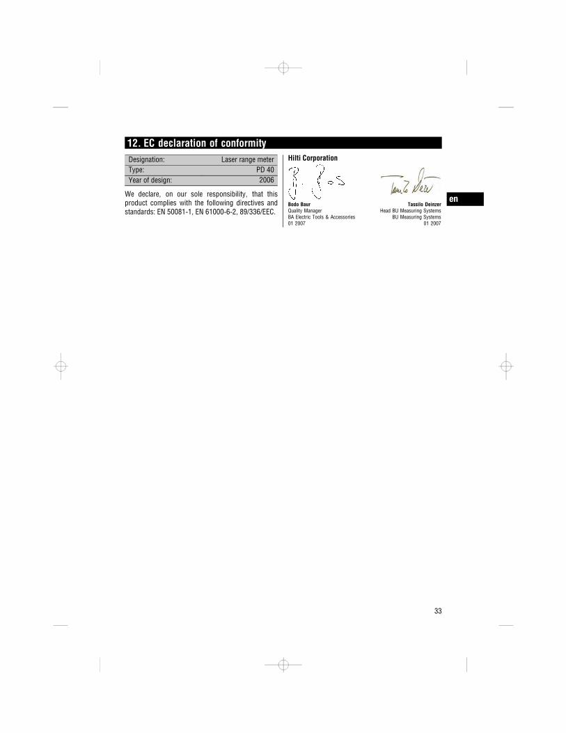
12. EC declaration of conformityDesignation: Laser range meterType: PD 40Year of design: 2006
We declare, on our sole responsibility, that thisproduct complies with the following directives andstandards: EN 50081 1, EN 61000 6 2, 89/336/EEC.
Hilti Corporation
Bodo Baur Tassilo DeinzerQuality Manager Head BU Measuring SystemsBA Electric Tools & Accessories BU Measuring Systems01 2007 01 2007
en
33

*320291*
3202
91
Hilti CorporationLI-9494 SchaanTel.: +423 / 234 21 11Fax: +423 / 234 29 65www.hilti.com
Hilti = registered trademark of Hilti Corp., Schaan W 3279 0307 00-Pos. 2 1 Printed in Liechtenstein © 2007Right of technical and programme changes reserved S. E. & O.
320291 / B