operating instruction - walther praezision
TRANSCRIPT
1
Operating instruction english
Revision C
Date 27.02.2015
Issuer NH This operating instruction is not subject to the updating
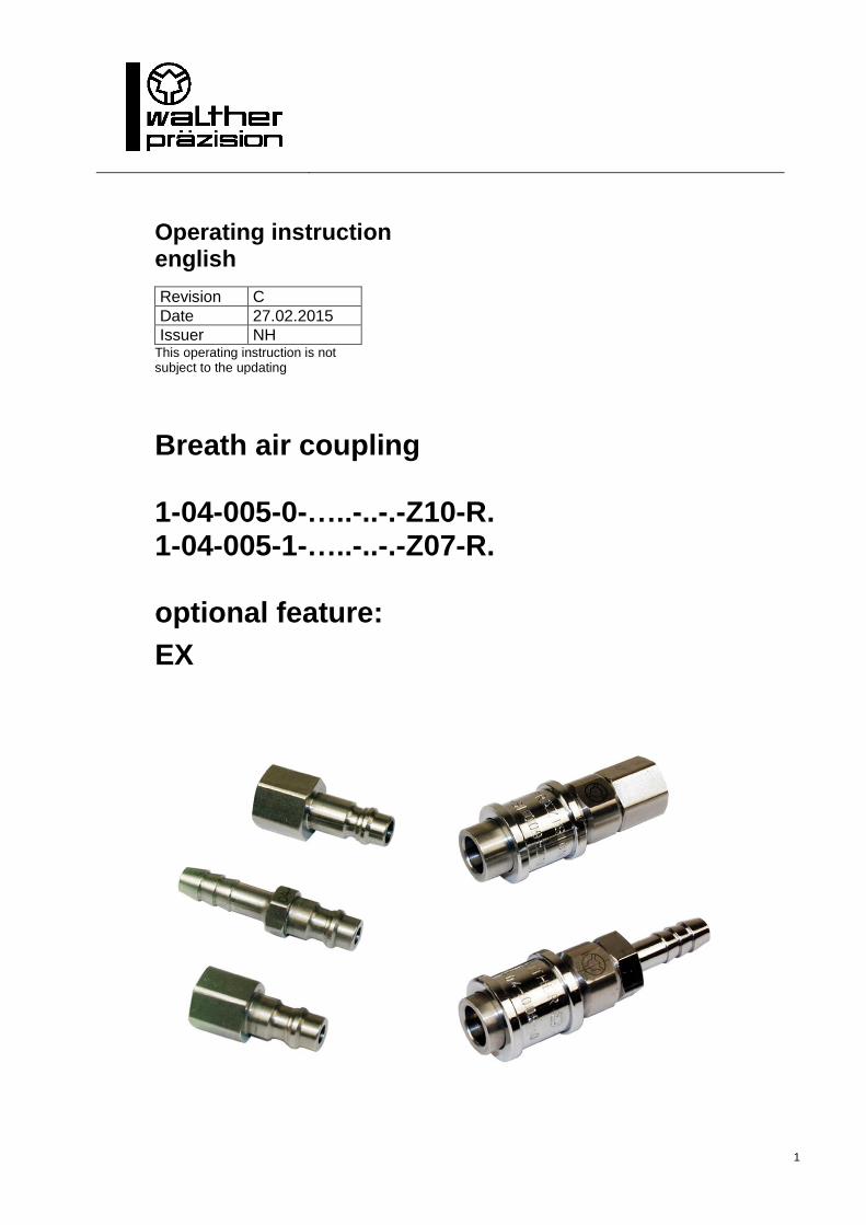
Breath air coupling 1-04-005-0-…..-..-.-Z10-R. 1-04-005-1-…..-..-.-Z07-R. optional feature:
EX
2
This coupling is a quality product, in which special attention has been paid to high functionality, ease of operation, safety and reliability. As an item of technical equipment this coupling is intended for use in the commercial, industrial area and for operators, who have been trained by specialists in the handling of technical systems / tools.
Customer care: As part of our individual customer care we will be happy to assist you in questions relating to use and operation and on any problems encountered.
Service and maintenance: In order to maintain the high technical performance capability and reliability of your coupling over many years, we recommend regular inspection and maintenance. We can thereby offer you optimum support by our Customer Service department and the conclusion of a service and maintenance contract. Please ask for a quotation.
WALTHER-PRÄZISION Carl Kurt Walther GmbH & Co. KG Westfalenstraße 2 42781 Haan
PO Box 42 04 44 42404 Haan
Germany
telephone: +49 (0) 2129 / 567-0 telefax: +49 (0) 2129 / 567-450
E-Mail: [email protected] Internet: www.walther-praezision.de
Contact: Application technology and service
Holger R. Figge telephone: +49 (0) 2129 / 567-591 telefax: +49 (0) 2129 / 567-590 mobile: +49 (0) 162 / 2090100 e-mail: [email protected]
Further addresses and telephone numbers of contacts can be found on the Internet on our homepage under http://www.walther-praezision.de/english/info_kontakt/service.
Operating instruction english
Type 04-005
List of Contents
3
1 List of Contents
1 LIST OF CONTENTS ........................................................................................................................................ 3
2 GENERAL ....................................................................................................................................................... 5
3 WARRANTY ................................................................................................................................................... 6
3.1 GENERAL ........................................................................................................................................................ 6 3.2 REPLACEMENT PARTS ........................................................................................................................................ 6
4 SAFETY INSTRUCTIONS ................................................................................................................................. 7
5 PRODUCT DESCRIPTION OF THE SELF SEALING COUPLING ............................................................................ 8
5.1 INTENDED USE ................................................................................................................................................. 8 5.2 TECHNICAL DATA .............................................................................................................................................. 8 5.3 OPTIONAL FEATURES ......................................................................................................................................... 9 5.4 EXTENDED PRODUCT DESCRIPTION FOR APPLICATION ACC. TO ATEX-GUIDE LINE 94/9/EG (SPECIAL DESIGN EX): ............... 9
5.4.1 General .................................................................................................................................................... 9 5.4.2 Extended marking ................................................................................................................................... 9
6 INSTALLATION INSTRUCTION ....................................................................................................................... 10
6.1 GENERAL ...................................................................................................................................................... 10 6.2 EXTENDED INSTALLATION INSTRUCTION FOR APPLICATION ACC. TO ATEX-GUIDELINE 94/9/EG ..................................... 11
6.2.1 Details for safe operation ...................................................................................................................... 11 6.2.2 Details for safe installation ................................................................................................................... 11 6.2.3 Details for a safe application area ........................................................................................................ 11
7 OPERATING INSTRUCTION ........................................................................................................................... 12
7.1 CONNECTION PROCESS..................................................................................................................................... 12 7.2 DISCONNECTION PROCESS ................................................................................................................................ 12
8 MAINTENANCE INSTRUCTION ...................................................................................................................... 13
8.1 MAINTENANCE: ............................................................................................................................................. 13 8.2 FUNCTIONAL TESTING: ..................................................................................................................................... 14
9 TEST ............................................................................................................................................................. 15
9.1 IMMERSION TEST ............................................................................................................................................ 15 9.1.1 Test setup of the connected state (schematic view) ............................................................................. 15 9.1.2 Test procedure ....................................................................................................................................... 15 9.1.3 Test disconnected .................................................................................................................................. 16 9.1.4 Test setup of the disconnected state (schematic view) ......................................................................... 16 9.1.5 Test procedure ....................................................................................................................................... 16 9.1.6 Test result .............................................................................................................................................. 16
9.2 PRESSURE TEST............................................................................................................................................... 17 9.2.1 Test setup of connected state (schematic view) .................................................................................... 17 9.2.2 Test procedure ....................................................................................................................................... 17 9.2.3 Test disconnected .................................................................................................................................. 18 9.2.4 Test setup of the disconnected state (schematic view) ......................................................................... 18 9.2.5 Test procedure ....................................................................................................................................... 18 9.2.6 Test result .............................................................................................................................................. 19
9.3 DOCUMENTATION .......................................................................................................................................... 19

Operating instruction english
Type 04-005
List of Contents
4
10 LUBRICATION ! ............................................................................................................................................. 20
11 STORAGE ..................................................................................................................................................... 20
12 SHUT-DOWN ................................................................................................................................................ 20
13 INDEX........................................................................................................................................................... 21
Operating instruction english
Type 04-005
General
5
2 General
This operating instruction contains all regulations for operation, commissioning and mainte-nance of the coupling. All information and notes in this operating instruction were collated while taking into considera-tion the valid regulations, the current engineering related status of development as well as our many years of experience and acquired knowledge. Translations of this operating instruction were also produced according to the best of knowledge. However, we cannot assume liability for any translation errors. The German version provided for this operating instruction is considered the authoritative ver-sion. The actual scope of delivery can deviate from the explanations and graphic representations described herein under certain circumstances, e.g. in the case of special designs, utilization of additional order options or because of state-of-the-art technical alterations. If you have any questions, please contact WALTHER-PRÄZISION.
This operating instruction must be read carefully before starting work on or with the equipment, in particular before commissioning! WALTHER-PRÄZISION assumes no liability for damage or faults arising from non-compliance with the instructions in this operating instruction.
The operating instruction must be kept directly with the equipment and be accessible to all persons who work on or with the equipment. It is not permitted for the operating instruction to be passed to third parties and if applicable this will incur damage compensation. All other rights reserved. Before commissioning the device must be checked for being not defective and its technically perfect function. The German version is the original. We reserve the right to make technical alterations to the product within the context of improving the usage properties and further development. The operating instruction remains our property. Any reproduction, use by or communication to third parties incurs a penalty and will be pursued by court action (copyright law against unfair competition, BGB [German Civil Code]). All rights reserved in the case of a patent award (Paragraph 7, Section. 1 of the patent law - PG) or entry as a patented design (Paragraph 5, Section 4 of the patented design law - GMG).
Operating instruction english
Type 04-005
Warranty
6
3 Warranty
3.1 General
The warranty is in accordance with:
The regulations agreed upon in the purchase contract and
The "General terms and conditions for delivery and service" of WALTHER-PRÄZISION using the version valid at the time the purchase contract came into force.
Generally excluded from the warranty are consumables. Typical consumables in products from WALTHER-PRÄZISION are, for example:
Seals
Springs
Electro plug contacts
Electrical cables and hoses which are subject to regular alternating bending or torsional stresses.
Components that are not normally subject to wear under the conditions to be ex-pected (environmental and usage) may become consumables if the described product is not operated according to the intended purpose or is operated with a disregard for the specifications in the operating instructions.
For example, electrical cables with sheathing that has been destroyed by extreme exposure to welding sparks would not fall under the warranty. In addition, wear to other components caused by unusual environmental condi-tions, not expressly coordinated with WALTHER-PRÄZISION, for example, high temperatures, dusts with an abrasive effect, high humidity or corrosive vapours and gases are not covered by the warranty.
Cycle, time or load dependant specifications for the replacement of certain compo-nents of the described product within the framework of maintenance are not war-ranty-relevant durability statements, they are instead recommendations designed as preventive maintenance to avoid standstill times during production.
3.2 Replacement parts
Warning! The use of non-Walther-parts can cause personal injuries, death as well as material damage.
Only original parts from WALTHER-PRÄZISION are to be used. These are to be installed according to their intended purpose.
When using third-party items or parts that have not been approved by WALTHER-PRÄZISION, all warranties, guarantees and service claims are voided without notification.
Operating instruction english
Type 04-005
Safety instructions
7
4 Safety instructions
Using these operating instruction does not release the customer from his obligation to comply with the pertinent work safety regulations e.g. operational safety regulations, etc. The duty to take due care by the operator of the couplings includes planning measures to ensure proper operation and monitoring their implementation.
Hazard notes
If the wrong product has been selected or if there is improper use or maintenance has been omitted, then hazards arise and personal injuries and material damage can occur from:
- hazardous emission of fluid or individual particles/coupling parts.
- function impairments of connected systems or tools.
- The metal parts of coupling and adaptor are not thermally protected. You can be burned if you touch these parts at high media temperatures. According to the ambient temperature valve lever and ring grip can also become unbearably hot. For that reason suitable, sufficiently long protective gloves should be worn.
The operator must in particular make sure that
- the materials, designs and seals which were used in the coupling halves were select-ed by in a responsible manner of customer designers, purchasers or operators by themselves for their medium, pressure and flow combinations.
- the couplings are only used according to the intended purpose.
- the couplings are only operated in a perfect, functioning condition.
- the operating instruction is always in a legible condition and is available in its entirety to operating personnel.
- the operating personnel are sufficiently acquainted with the working method and the safety notes for the coupling.
- no safety devices must be removed and/or deactivated during operation of the couplings.
- before installing or dismantling the couplings, you have made sure that the couplings have not been pressurized.
After completing assembly and installation work and before commissioning the coupling, the following items have to be observed:
Check once again that all screw connections are securely fitted.
Before commissioning the couplings, a function test must be carried out (see maintenance and function test).
Operating instruction english
Type 04-005
Product description of the self sealing coupling
8
5 Product description of the self sealing coupling
Coupling connection consists of:
- self sealing coupling 1-04-005-0-.....-..-.-Z10-R. - self sealing adaptor 1-04-005-1-.....-..-.-Z07-R.
5.1 Intended use
- The coupling shall only be used to connect two lines.
- When disconnected, the coupling unit blocks further media discharge by means of valves only at one side (coupling side).
- The coupling- and decoupling process is manually operated.
- The coupling is equipped with an automatic lock, i. e.:
one-hand operation
- The coupling is equipped with an automatically engaging train control.
- The coupling unit is easy to operate, also with gloves by handle bolsters at the releasing sleeve.
- The coupling is especially suitable for the following media / applications, provided the correct coupling material as well as sealing material were chosen:
breath air
- For all other possible applications please contact WALTHER-Präzision.
5.2 Technical data
CAUTION For normed threaded connections, when specifying the operating pressure, the highest permitted operating pressure of the connection must be taken into account!
Differing higher or lower operating pressures are possible according to material characteristics or the connection. This operating pressure is to be taken from the project-specific documentation.
operating pressure maximum: 23 bar
Cv- value: 0.80
range of temperature: -40°C to +150°C
- The coupling is not determined for any types of use and technical values other than those listed here.
- Safe operation is not guaranteed if the coupling is used contrary to ist intended use and technical values
- The operator of the coupling is responsible for all personal injuries or material damage that occur from non-intended use and disregard of the technical values; the manufacturer as-sumes no responsibility in these cases.
Operating instruction english
Type 04-005
Product description of the self sealing coupling
9
5.3 Optional Features
EX = ATEX – version
5.4 Extended product description for application acc. to ATEX-guide line 94/9/EG (special design EX):
5.4.1 General
Only non-sparkling materials may be used. Non-sparkling materials are 1.4305 or equivalent materials. Furthermore brass with different surfaces (f. ex. chrome-plated, nickel-plated).
Further on it must be assured that the seal is resistant against and suitable for the flowing through media. Also the temperature resistance of the seals must be guaranteed. This must also be considered for the marking acc. to chapter 5.5.2.
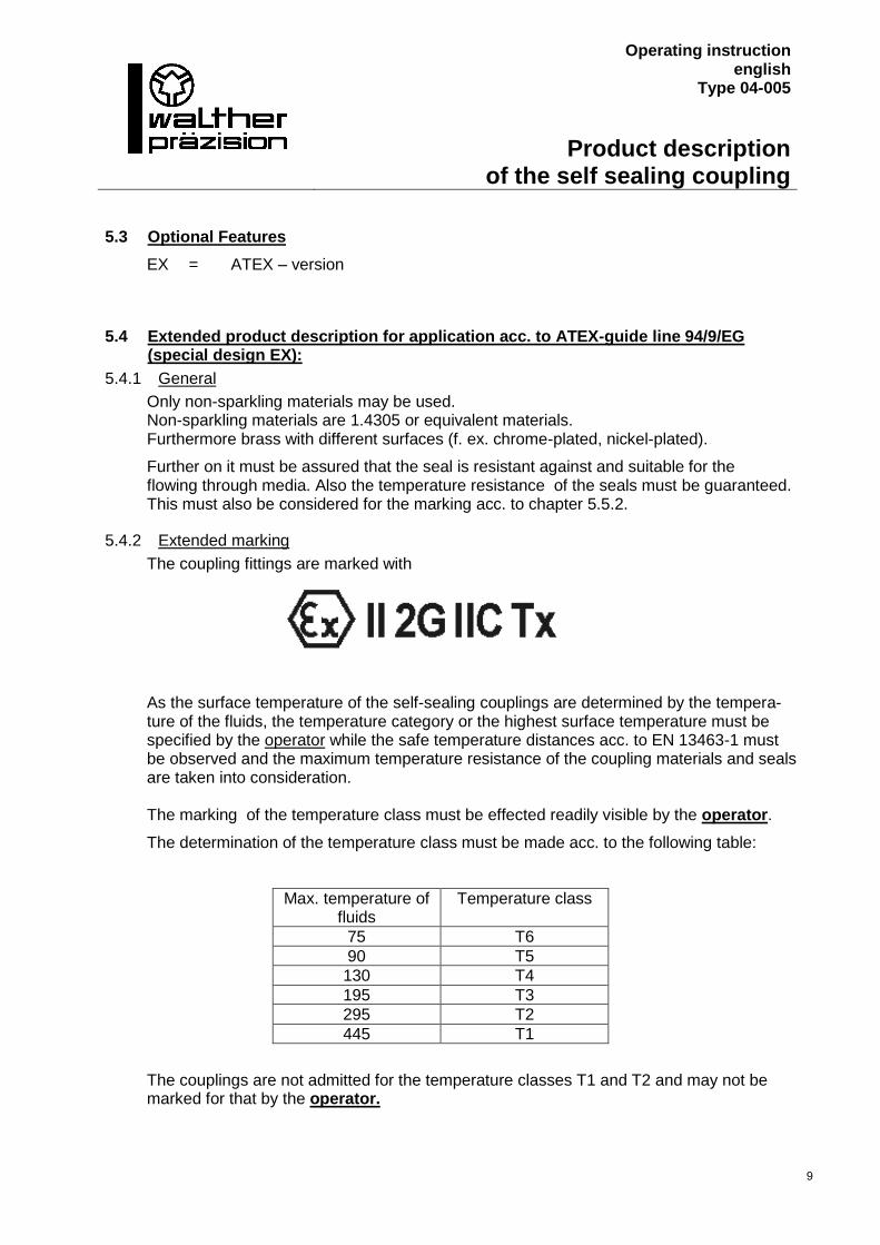
5.4.2 Extended marking
The coupling fittings are marked with
As the surface temperature of the self-sealing couplings are determined by the tempera-ture of the fluids, the temperature category or the highest surface temperature must be specified by the operator while the safe temperature distances acc. to EN 13463-1 must be observed and the maximum temperature resistance of the coupling materials and seals are taken into consideration. The marking of the temperature class must be effected readily visible by the operator.
The determination of the temperature class must be made acc. to the following table:
Max. temperature of fluids
Temperature class
75 T6
90 T5
130 T4
195 T3
295 T2
445 T1
The couplings are not admitted for the temperature classes T1 and T2 and may not be marked for that by the operator.
Operating instruction english
Type 04-005
Installation instruction
10
6 Installation Instruction
6.1 General
Install the self sealing coupling into the network in due consideration of the general accident prevention regulations, so that:
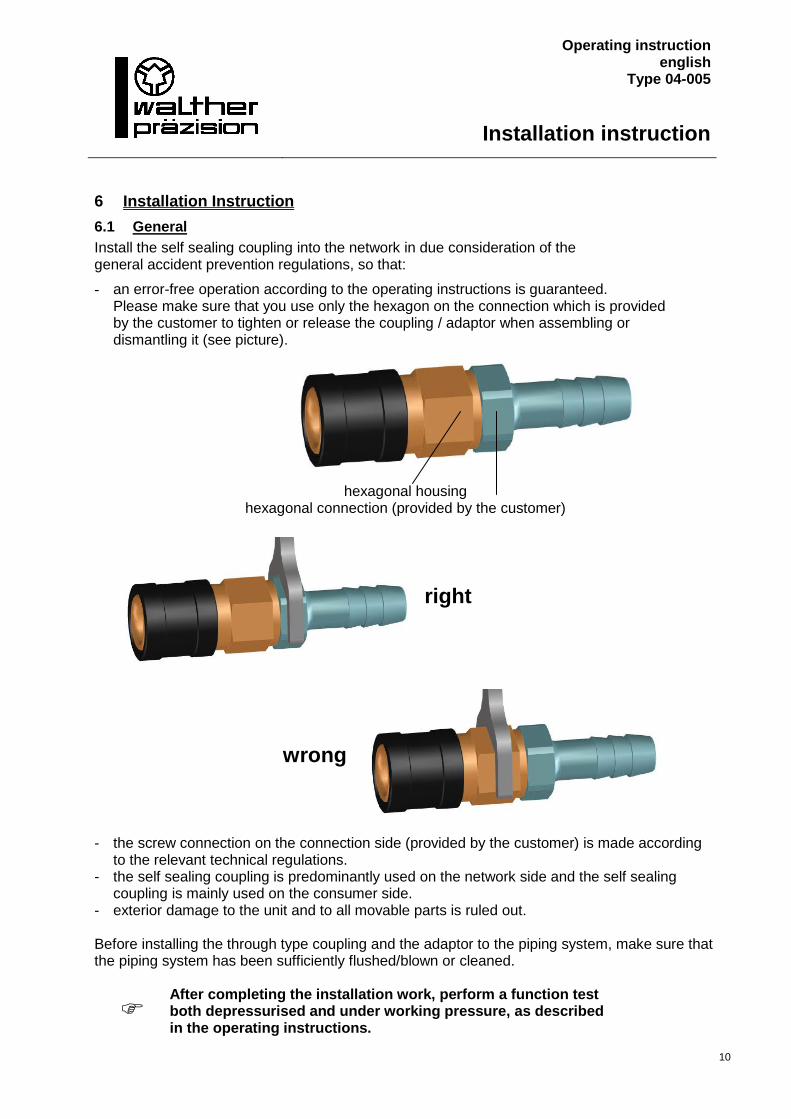
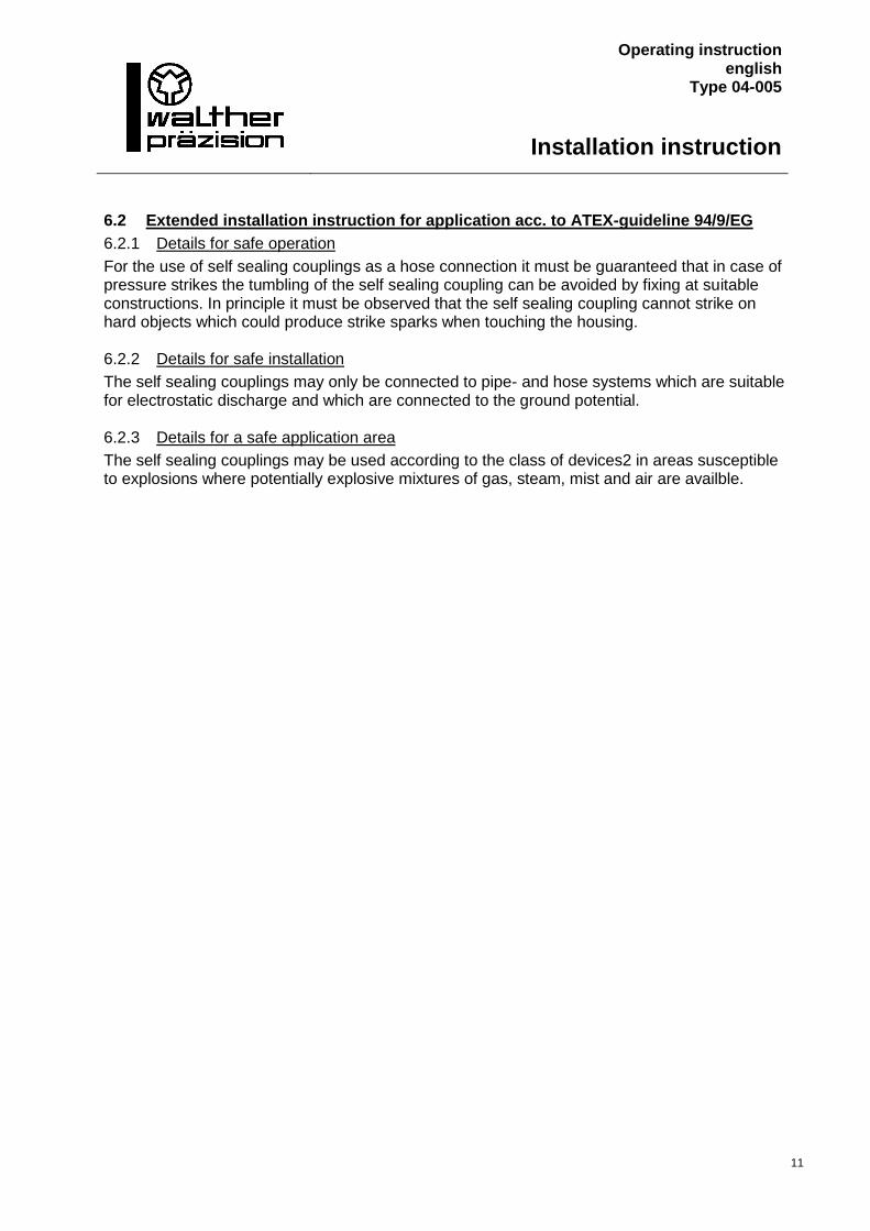
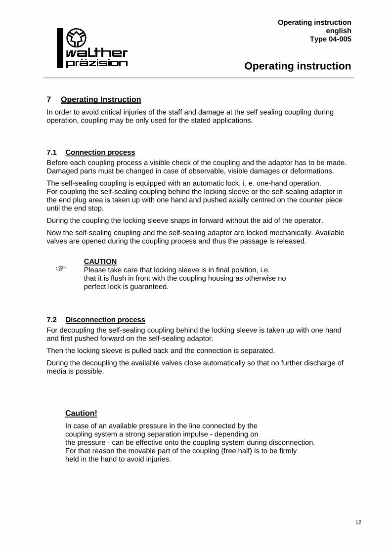
- an error-free operation according to the operating instructions is guaranteed. Please make sure that you use only the hexagon on the connection which is provided by the customer to tighten or release the coupling / adaptor when assembling or dismantling it (see picture).
hexagonal housing hexagonal connection (provided by the customer)
right
wrong
- the screw connection on the connection side (provided by the customer) is made according to the relevant technical regulations.
- the self sealing coupling is predominantly used on the network side and the self sealing coupling is mainly used on the consumer side.
- exterior damage to the unit and to all movable parts is ruled out. Before installing the through type coupling and the adaptor to the piping system, make sure that the piping system has been sufficiently flushed/blown or cleaned.
After completing the installation work, perform a function test both depressurised and under working pressure, as described in the operating instructions.
Operating instruction english
Type 04-005
Installation instruction
11
6.2 Extended installation instruction for application acc. to ATEX-guideline 94/9/EG
6.2.1 Details for safe operation
For the use of self sealing couplings as a hose connection it must be guaranteed that in case of pressure strikes the tumbling of the self sealing coupling can be avoided by fixing at suitable constructions. In principle it must be observed that the self sealing coupling cannot strike on hard objects which could produce strike sparks when touching the housing. 6.2.2 Details for safe installation
The self sealing couplings may only be connected to pipe- and hose systems which are suitable for electrostatic discharge and which are connected to the ground potential. 6.2.3 Details for a safe application area
The self sealing couplings may be used according to the class of devices2 in areas susceptible to explosions where potentially explosive mixtures of gas, steam, mist and air are availble.
Operating instruction english
Type 04-005
Operating instruction
12
7 Operating Instruction
In order to avoid critical injuries of the staff and damage at the self sealing coupling during operation, coupling may be only used for the stated applications.
7.1 Connection process
Before each coupling process a visible check of the coupling and the adaptor has to be made. Damaged parts must be changed in case of observable, visible damages or deformations.
The self-sealing coupling is equipped with an automatic lock, i. e. one-hand operation. For coupling the self-sealing coupling behind the locking sleeve or the self-sealing adaptor in the end plug area is taken up with one hand and pushed axially centred on the counter piece until the end stop.
During the coupling the locking sleeve snaps in forward without the aid of the operator.
Now the self-sealing coupling and the self-sealing adaptor are locked mechanically. Available valves are opened during the coupling process and thus the passage is released.
CAUTION Please take care that locking sleeve is in final position, i.e. that it is flush in front with the coupling housing as otherwise no perfect lock is guaranteed.
7.2 Disconnection process
For decoupling the self-sealing coupling behind the locking sleeve is taken up with one hand and first pushed forward on the self-sealing adaptor.
Then the locking sleeve is pulled back and the connection is separated.
During the decoupling the available valves close automatically so that no further discharge of media is possible.
Caution!
In case of an available pressure in the line connected by the coupling system a strong separation impulse - depending on the pressure - can be effective onto the coupling system during disconnection. For that reason the movable part of the coupling (free half) is to be firmly held in the hand to avoid injuries.
Operating instruction english
Type 04-005
Maintenance and Functional instruction
13
8 Maintenance Instruction
The WALTHER – coupling units are to be handled in such a way exterior damage to the elements as well as to all moving parts is prevented.
In order to minimise activation forces and to extend the lifetime of the coupling unit, we recommend lightly lubricating the connecting surfaces if this is permitted (see lubrication instructions).
In order to always ensure the functionality of the coupling unit and thus the protection of the operator, maintenance and functional testing must be carried out independantly of the operating instructions and at a suitable interval.
Note! In the event of maintenance that is carried out by neither WALTHER-PRÄZISION nor by personnel trained by WALTHER-PRÄZISION, the warranty of WALTHER-PRÄZISION is voided. This does not apply when maintenance is carried out by personnel trained by WALTHER-PRÄZISION.
Note! In the event of media that is hazardous to health a coupling unit returned to WALTHER-PRÄZISION must be sent in a fully cleaned state. No media hazardous to health may be released from the coupling unit during the dismantling process. The sending party (customer) is responsible for this.
8.1 Maintenance:
- With the coupling unit in the decoupled state, carry out an external visual check for damages and contamination.
- Contamination in the functional area that can be accessed from the outside (seal region, activation elements) must be removed by wiping.
In the event of damaged, cracked or corroded parts, the coupling unit must be removed and sent to WALTHER-PRÄZISION for repair (see Note).
In the event of worn, brittle or overaged seals as well as serious contamination, it is the decision of the customer whether they wish to send the coupling unit WALTHER-PRÄZISION or whether they wish to repair it themselves (see Note).
Operating instruction english
Type 04-005
Maintenance and Functional instruction
14
8.2 Functional testing:
As described in the operating instructions, the coupling unit is coupled, pressure is applied and it is decoupled and this process is carried out multiple times.
In doing so, the following should be taken into consideration: - Proper, easy functionality when coupling and decoupling.
- Sealing of the coupling unit in the coupled and decoupled state.
In the event of damaged, cracked or corroded parts, the coupling unit must be removed and sent to WALTHER-PRÄZISION for repair (see Note).
In the event of worn, brittle or overaged seals as well as serious contamination, it is the decision of the customer whether they wish to send the coupling unit to WALTHER-PRÄZISION or whether they wish to repair it themselves (see Note).
Note!
When repairing, a pressure and sealing test must always be carried out. This may also be completed by means of the working process. The procedure and scope of this test is described in the "Test” section.
Operating instruction english
Type 04-005
Test
15
9 Test
For applications up to 2 bar, WALTHER-PRÄZISION recommends a leakage test by immersion trial. For applications above 2 bar, it is up to the user, if a leakage test by immersion trial or a pressure test by test bench has to take place.
9.1 Immersion test
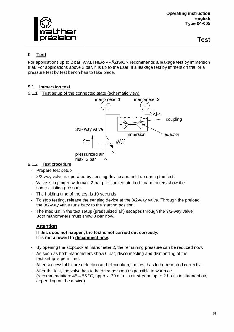
9.1.1 Test setup of the connected state (schematic view)
manometer 1 manometer 2
coupling
3/2- way valve immersion adaptor
pressurized air max. 2 bar
9.1.2 Test procedure
- Prepare test setup
- 3/2-way valve is operated by sensing device and held up during the test.
- Valve is impinged with max. 2 bar pressurized air, both manometers show the same existing pressure.
- The holding time of the test is 10 seconds.
- To stop testing, release the sensing device at the 3/2-way valve. Through the preload, the 3/2-way valve runs back to the starting position.
- The medium in the test setup (pressurized air) escapes through the 3/2-way valve. Both manometers must show 0 bar now.
Attention
If this does not happen, the test is not carried out correctly. It is not allowed to disconnect now.
- By opening the stopcock at manometer 2, the remaining pressure can be reduced now.
- As soon as both manometers show 0 bar, disconnecting and dismantling of the test setup is permitted.
- After successful failure detection and elimination, the test has to be repeated correctly.
- After the test, the valve has to be dried as soon as possible in warm air (recommendation: 45 – 55 °C, approx. 30 min. in air stream, up to 2 hours in stagnant air, depending on the device).
Operating instruction english
Type 04-005
Test
16
9.1.3 Test disconnected
Test setup and procedure are identic for both coupling and adaptor.
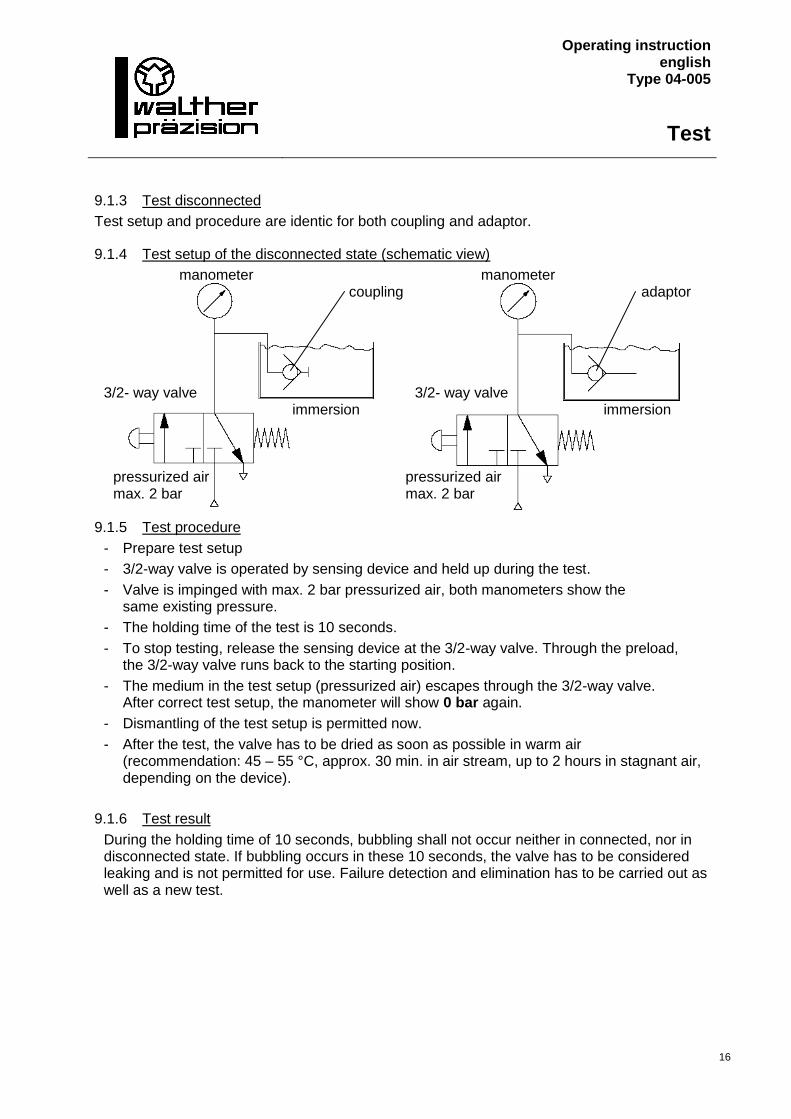
9.1.4 Test setup of the disconnected state (schematic view)
manometer manometer coupling adaptor
3/2- way valve 3/2- way valve immersion immersion
pressurized air pressurized air max. 2 bar max. 2 bar
9.1.5 Test procedure
- Prepare test setup
- 3/2-way valve is operated by sensing device and held up during the test.
- Valve is impinged with max. 2 bar pressurized air, both manometers show the same existing pressure.
- The holding time of the test is 10 seconds.
- To stop testing, release the sensing device at the 3/2-way valve. Through the preload, the 3/2-way valve runs back to the starting position.
- The medium in the test setup (pressurized air) escapes through the 3/2-way valve. After correct test setup, the manometer will show 0 bar again.
- Dismantling of the test setup is permitted now.
- After the test, the valve has to be dried as soon as possible in warm air (recommendation: 45 – 55 °C, approx. 30 min. in air stream, up to 2 hours in stagnant air, depending on the device).
9.1.6 Test result
During the holding time of 10 seconds, bubbling shall not occur neither in connected, nor in disconnected state. If bubbling occurs in these 10 seconds, the valve has to be considered leaking and is not permitted for use. Failure detection and elimination has to be carried out as well as a new test.
Operating instruction english
Type 04-005
Test
17
9.2 Pressure test
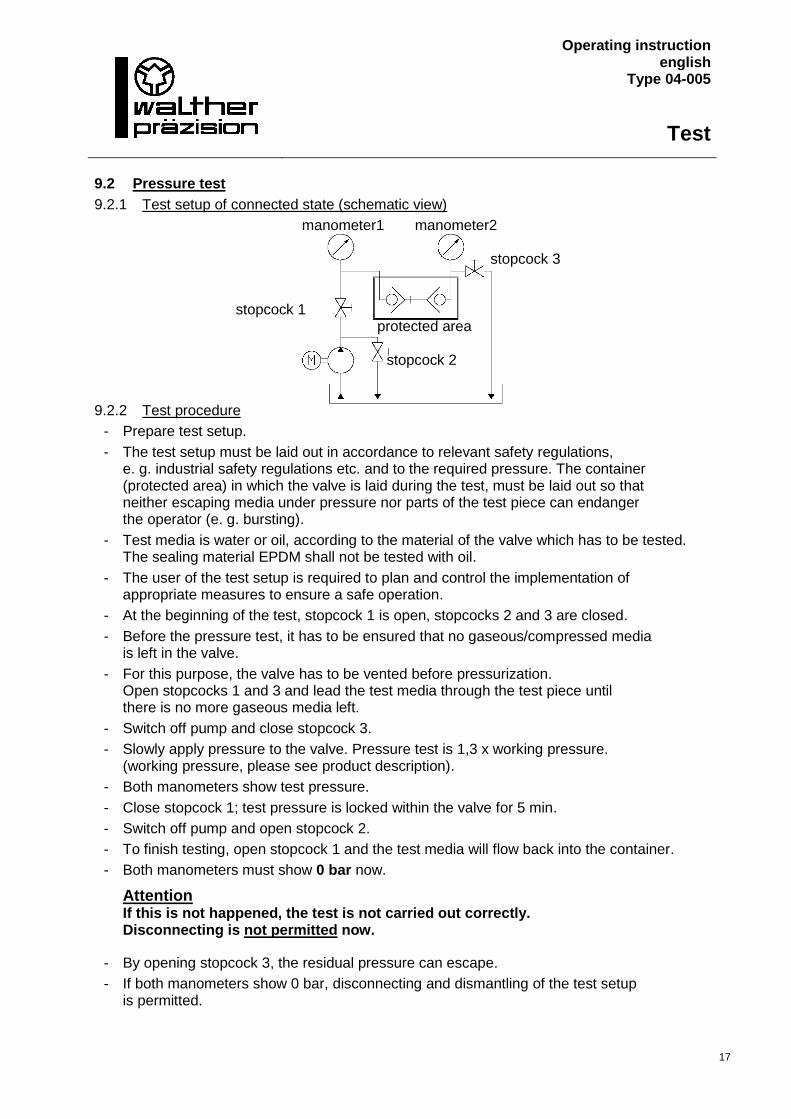
9.2.1 Test setup of connected state (schematic view)
manometer1 manometer2
stopcock 3
stopcock 1
protected area
stopcock 2 9.2.2 Test procedure
- Prepare test setup.
- The test setup must be laid out in accordance to relevant safety regulations, e. g. industrial safety regulations etc. and to the required pressure. The container (protected area) in which the valve is laid during the test, must be laid out so that neither escaping media under pressure nor parts of the test piece can endanger the operator (e. g. bursting).
- Test media is water or oil, according to the material of the valve which has to be tested. The sealing material EPDM shall not be tested with oil.
- The user of the test setup is required to plan and control the implementation of appropriate measures to ensure a safe operation.
- At the beginning of the test, stopcock 1 is open, stopcocks 2 and 3 are closed.
- Before the pressure test, it has to be ensured that no gaseous/compressed media is left in the valve.
- For this purpose, the valve has to be vented before pressurization. Open stopcocks 1 and 3 and lead the test media through the test piece until there is no more gaseous media left.
- Switch off pump and close stopcock 3.
- Slowly apply pressure to the valve. Pressure test is 1,3 x working pressure. (working pressure, please see product description).
- Both manometers show test pressure.
- Close stopcock 1; test pressure is locked within the valve for 5 min.
- Switch off pump and open stopcock 2.
- To finish testing, open stopcock 1 and the test media will flow back into the container.
- Both manometers must show 0 bar now.
Attention If this is not happened, the test is not carried out correctly. Disconnecting is not permitted now.
- By opening stopcock 3, the residual pressure can escape.
- If both manometers show 0 bar, disconnecting and dismantling of the test setup is permitted.
Operating instruction english
Type 04-005
Test
18
- After successful failure detection and elimination, the test has to be repeated correctly.
- After the test, the valve has to be dried as soon as possible in warm air (recommendation: 45 – 55 °C, approx. 30 min. in air stream, up to 2 hours in stagnant air, depending on the device).
9.2.3 Test disconnected
Test setup and test procedure are identic for both coupling and adaptor.
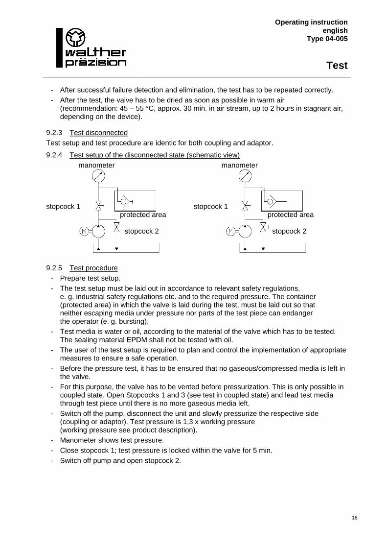
9.2.4 Test setup of the disconnected state (schematic view)
manometer manometer
stopcock 1 stopcock 1
protected area protected area
stopcock 2 stopcock 2
9.2.5 Test procedure
- Prepare test setup.
- The test setup must be laid out in accordance to relevant safety regulations, e. g. industrial safety regulations etc. and to the required pressure. The container (protected area) in which the valve is laid during the test, must be laid out so that neither escaping media under pressure nor parts of the test piece can endanger the operator (e. g. bursting).
- Test media is water or oil, according to the material of the valve which has to be tested. The sealing material EPDM shall not be tested with oil.
- The user of the test setup is required to plan and control the implementation of appropriate measures to ensure a safe operation.
- Before the pressure test, it has to be ensured that no gaseous/compressed media is left in the valve.
- For this purpose, the valve has to be vented before pressurization. This is only possible in coupled state. Open Stopcocks 1 and 3 (see test in coupled state) and lead test media through test piece until there is no more gaseous media left.
- Switch off the pump, disconnect the unit and slowly pressurize the respective side (coupling or adaptor). Test pressure is 1,3 x working pressure (working pressure see product description).
- Manometer shows test pressure.
- Close stopcock 1; test pressure is locked within the valve for 5 min.
- Switch off pump and open stopcock 2.
Operating instruction english
Type 04-005
Test
19
- To finish testing, open stopcock 1 and the test media will flow back into the container. The manometer must show 0 bar after correct test setup.
- The test setup can be dismantled.
- After the test, the valve has to be dried as soon as possible in warm air (recommendation: 45 – 55 °C, approx. 30 min. in air stream, up to 2 hours in stagnant air, depending on the device).
9.2.6 Test result
After 5 min. of testing, the pressure decrease must not exceed 5 % in connected and disconnected state with a test pressure up to 700 bar. With a test pressure of more than 700 bar, the pressure decrease must not exceed 3 %. If the pressure loss is higher or if media escapes obviously, the valve is to be considered leaking and is not permitted for use. Failure detection and elimination as well as a new test are required.
9.3 Documentation
Tests have to be documented with registration of test pressure, test media, name/date and signature.
Operating instruction english
Type 04-005
Lubrication Storage
Shut down
20
10 Lubrication !
In order to minimize the activation forces and to extend the lifetime of the coupling, we recommend cleaning and lightly greasing the connecting surfaces at suitable intervals as long as there is no risk that contamination in the vicinity will cause increased wear in combination with grease.
Lubrication is not carried out if the application does not permit it (e.g. in medical technology).
The selection of the lubrication is determined by the operator of the coupling and their purchasing options.
The connecting surfaces may only be lubricated if the operating conditions permit it.
Thus: - The lubrication must be selected in accordance with compatibility with the seal quality
and material.
- Media/lubrication combinations in which the lubrication properties are changed (e.g. turns to resin) must be avoided.
- Media/lubrication combinations that prevent safe operating conditions (e.g. lubrication/oxygen) must be avoided.
The lubrication interval depends on the framework conditions and the use of the application and is determined by the operator.
11 Storage
The coupling must be stored in a way that it cannot be damaged.
To avoid damage or dirt the transportation covers must be attached on all connections.
The storage conditions of the coupling depend on the guidelines applicable to the gaskets, since improper storage can lead to deterioration of the gaskets.
The following points must be observed:
- The gaskets must be stored dry.
- For the preservation of the gaskets, the gaskets should not be stored where they are ex-posed to the effects of daylight.
- For protection against oxygen, the gaskets should be stored in the original packaging.
12 Shut-down
At the end of the service life the coupling or its components have to be disposed non-polluting and according to the legal regulations.
For that the local public or private disposal societies should be taken.
Operating instruction english
Type 04-005
Index
21
13 Index
A
According to intended purpose ......................... 7 Activation forces .............................................. 20 Adaptorl ............................................................. 7 Assembly ........................................................... 7
B
breath air ........................................................... 8
C
Commissioning .............................................. 5, 7 connection ......................................................... 8 Connection process ......................................... 12 Consumables ..................................................... 6 Contact .............................................................. 2 coupling ......................................................... 5, 7 Coupling ................................................... 7, 8, 20 Customer care, individual .................................. 2
D
Damage.............................................................. 7 Damage compensation ...................................... 5 Disconnection process..................................... 12 Dismantling ........................................................ 7 Disposal societies ............................................ 20 Disregard ........................................................... 8
E
Environmental conditions ................................. 6
F
Fluid ................................................................... 7 Fully cleaned state ........................................... 13 Function ............................................................. 7 Function test ...................................................... 7
G
General .............................................................. 5 General terms and conditions for delivery and
service............................................................ 6 Guarantees, void without notification .............. 6 Guidelines applicable to the gaskets ............... 20
H
Hazard notes ..................................................... 7 Hazardous emission .......................................... 7
I
Implementation .................................................7 Improving ...........................................................5 Index ................................................................ 21 Installation Instruction .................................... 10 Intended use ......................................................8
K
kontrollieren............................................... 17, 18
L
Legible condition ................................................7 Liability ...............................................................5 Lifetime ...................................................... 13, 20 List of Contents ..................................................3 Lubrication in accordance with compatibility
with the seal quality .................................... 20
M
Maintenance .................................................. 5, 7 Maintenance Instruction ................................. 13 Media temperatures ..........................................7 Media that is hazardous to health .................. 13
N
No liability ..........................................................5
O
one-hand operation ...........................................8 Operated, not according to the intended
purpose ..........................................................6 Operated, with a disregard for the
specifications ..................................................6 Operating Instruction ...................................... 12 Operational safety regulations...........................7 operator .............................................................7 Optional Features ...............................................9 Original parts ......................................................6
P
Parts, damaged .......................................... 13, 14 Perfect, functioning condition ...........................7 personnel trained by Walther-Präzision ......... 13 pressurized .........................................................7 Product description ............................................8 Protective gloves ................................................7
Operating instruction english
Type 04-005
Index
22
Purchase contract .............................................. 6
R
Regulations ........................................................ 5 responsible ........................................................ 8 Responsiblity ................................................... 13
S
Safety devices .................................................... 7 Safety instructions ............................................. 7 Scope of delivery, actual ................................... 5 Screw connections............................................. 7 Seal ............................................................ 13, 14 Sealing test ...................................................... 14 self sealing adaptor ........................................... 8 self sealing coupling .................................... 8, 12 Service and maintenance contract .................... 2 Service claims, void without notification .......... 6 Shut-down ....................................................... 20 Storage ............................................................ 20 Storage conditions ........................................... 20 Systems .............................................................. 7
T
Technical data ....................................................8 Technical values .................................................8 Temperaturklasse...............................................9 Thermally ...........................................................7 Third-party items................................................6 Tools ...................................................................7 Translation errors ...............................................5 Transportation covers ..................................... 20 Types of use .......................................................8
V
Visual check ..................................................... 13
W
Warrantiy, void without notification .................6 Warranty, excluded from ...................................6 Work safety regulations .....................................7 Working method ................................................7 Wrong product selection ...................................7