operating guide aft 06,17€¦ · montiertem antrieb durchführen. ventil ist ohne antrieb offen....
TRANSCRIPT
© Danfoss | 2017.07 VI.GA.N6.81 | 1
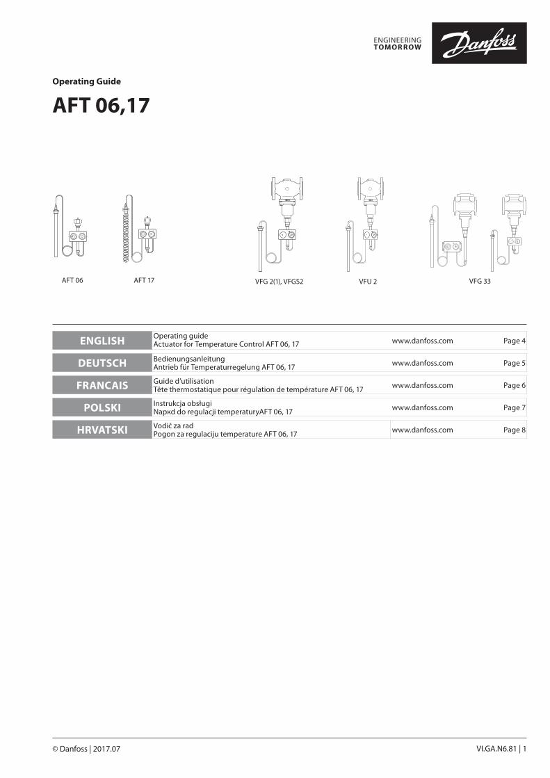
ENGLISH Operating guide Actuator for Temperature Control AFT 06, 17 www.danfoss.com Page 4
DEUTSCH Bedienungsanleitung Antrieb für Temperaturregelung AFT 06, 17 www.danfoss.com Page 5
FRANCAIS Guide d’utilisation Tête thermostatique pour régulation de température AFT 06, 17 www.danfoss.com Page 6
POLSKI Instrukcja obsługi Napкd do regulacji temperaturyAFT 06, 17 www.danfoss.com Page 7
HRVATSKI Vodič za rad Pogon za regulaciju temperature AFT 06, 17 www.danfoss.com Page 8
AFT 06,17Operating Guide
������
�����
�����
1211
1098
76
5=10 C
AFT 06 AFT 17 VFG 2(1), VFGS2 VFU 2 VFG 33
2 | © Danfoss | 2017.07 VI.GA.N6.81
AFT 06,17
①
VFG 33B
ABA
②
①
②
MAINTENANCEFREE
①
����
��� �
��������
VFG .., VFU 2
������
��
� ��
�����
②
����
��� �
��������
������
��
� ��
�����
VFG .., VFU 2, VFGS 2
��
��������
①
��
��������
②
③
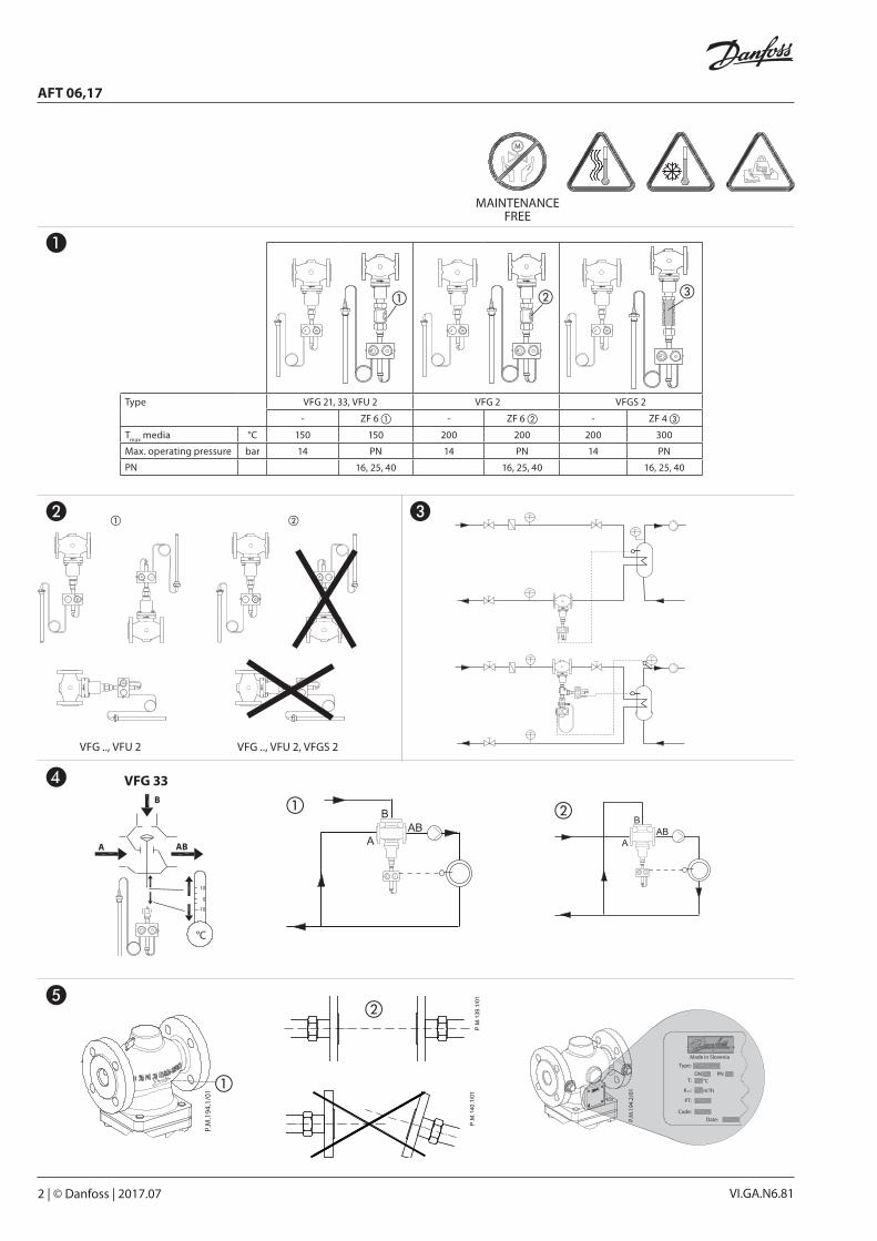
Type VFG 21, 33, VFU 2 VFG 2 VFGS 2
- ZF 6 ① - ZF 6 ② - ZF 4 ③
Tmax
media °C 150 150 200 200 200 300
Max. operating pressure bar 14 PN 14 PN 14 PN
PN 16, 25, 40 16, 25, 40 16, 25, 40
❶
❷ ❸
❹
❺
© Danfoss | 2017.07 | 3VI.GA.N6.81
AFT 06,17
×10 = °C④
⑤
②
③
5×10 =50 °C
②
④
⑥
VFG 2, VFG 21, VFGS 2 VFU 2
⑦
① ②
①46 mm
③
VFG 33
⑧ B
A AB
②①
③①
380
- 401
AFT 06
��
���
����
���AFT 17
①
②
④
②
❼
⓬
❻
❽
➒ ❿
⓫
4 | © Danfoss | 2017.07 VI.GA.N6.81
AFT 06,17
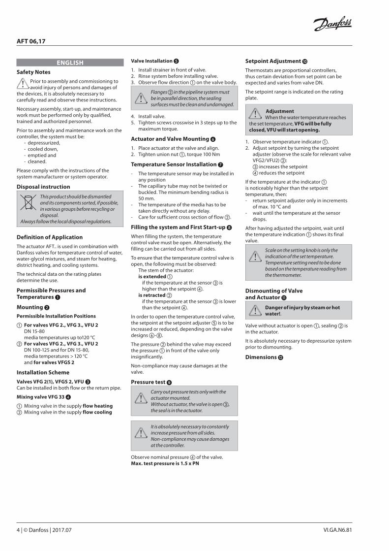
ENGLISHSafety Notes
Prior to assembly and commissioning to avoid injury of persons and damages of
the devices, it is absolutely necessary to carefully read and observe these instructions.
Necessary assembly, start-up, and maintenance work must be performed only by qualified, trained and authorized personnel.
Prior to assembly and maintenance work on the controller, the system must be:
- depressurized,- cooled down,- emptied and- cleaned.
Please comply with the instructions of the system manufacturer or system operator.
Disposal instruction
This product should be dismantled and its components sorted, if possible, in various groups before recycling or disposal.
Always follow the local disposal regulations.
Definition of Application
The actuator AFT.. is used in combination with Danfoss valves for temperature control of water, water-glycol mixtures, and steam for heating, district heating, and cooling systems.
The technical data on the rating plates determine the use.
Permissible Pressures and Temperatures ❶
Mounting ❷
Permissible Installation Positions
① For valves VFG 2., VFG 3., VFU 2 DN 15-80
media temperatures up to120 °C② For valves VFG 2., VFG 3., VFU 2 DN 100-125 and for DN 15-80,
media temperatu res > 120 °C and for valves VFGS 2
Installation Scheme
Valves VFG 2(1), VFGS 2, VFU ❸Can be installed in both flow or the return pipe.
Mixing valve VFG 33 ❹
① Mixing valve in the supply flow heating② Mixing valve in the supply flow cooling
Valve Installation ❺
1. Install strainer in front of valve.2. Rinse system before installing valve.3. Observe flow direction ① on the valve body.
Flanges ② in the pipeline system must be in parallel direction, the sealing surfaces must be clean and undamaged.
4. Install valve.5. Tighten screws crosswise in 3 steps up to the
maximum torque.
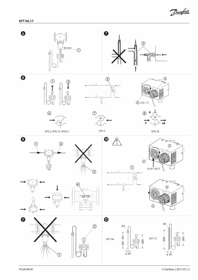
Actuator and Valve Mounting ❻
1. Place actuator at the valve and align.2. Tighten union nut ①, torque 100 Nm
Temperature Sensor Installation ❼
- The temperature sensor may be installed in any position
- The capillary tube may not be twisted or buckled. The minimum bending radius is 50 mm.
- The temperature of the media has to be taken directly without any delay.
- Care for sufficient cross section of flow ②.
Filling the system and First Start-up ❽
When filling the system, the temperature control valve must be open. Alternatively, the filling can be carried out from all sides.
To ensure that the temperature control valve is open, the following must be observed:
The stem of the actuator:is extended ①
if the temperature at the sensor ③ is higher than the setpoint ④.
is retracted ② if the temperature at the sensor ③ is lower than the setpoint ④.
In order to open the temperature control valve, the setpoint at the setpoint adjuster ⑤ is to be increased or reduced, depending on the valve designs ⑥-⑧.
The pressure ② behind the valve may exceed the pressure ① in front of the valve only insignificantly.
Non-compliance may cause damages at the valve.
Pressure test ➒
Carry out pressure tests only with the actuator mounted. Without actuator, the valve is open ③, the seal is in the actuator.
It is absolutely necessary to constantly increase pressure from all sides. Non-compliance may cause damages at the controller.
Observe nominal pressure ④ of the valve. Max. test pressure is 1.5 x PN
Setpoint Adjustment ❿
Thermostats are proportional controllers, thus certain deviation from set point can be expected and varies from valve DN.
The setpoint range is indicated on the rating plate.
AdjustmentWhen the water temperature reaches
the set temperature, VFG will be fully closed, VFU will start opening.
1. Observe temperature indicator ①.2. Adjust setpoint by turning the setpoint
adjuster (observe the scale for relevant valve VFG2/VFU2) ②: ③ increases the setpoint ④ reduces the setpoint
If the temperature at the indicator ① is noticeably higher than the setpoint temperature, then:- return setpoint adjuster only in increments
of max. 10 °C and - wait until the temperature at the sensor
drops.
After having adjusted the setpoint, wait until the temperature indication ① shows its final value.
Scale on the setting knob is only the indication of the set temperature. Temperature setting need to be done based on the temperature reading from the thermometer.
Dismounting of Valve and Actuator ⓫
Danger of injury by steam or hot water!.
Valve without actuator is open ①, sealing ② is in the actuator.
It is absolutely necessary to depressurize system prior to dismounting.
Dimensions ⓬
© Danfoss | 2017.07 | 5VI.GA.N6.81
AFT 06,17
DEUTSCHSicherheitshinweise
Um Verletzungen an Personen und Schäden am Gerät zu vermeiden, ist diese
Anleitung vor der Montage unbedingt zu beachten.
Montage, Inbetriebnahme und Wartungsarbeiten dürfen nur von sachkundigen und autorisierten Personen durchgeführt werden.
Vor Montage und Wartungsarbeiten am Regler die Anlage:
- drucklos machen, - abkühlen,- entleeren und - reinigen.
Die Vorgaben des Anlagenherstellers und Anlagenbetreibers sind zu beachten.
Anweisung zur Entsorgung
Dieses Produkt sollte ausgebaut und in dessen Bestandteile zerlegt werden. Sortieren Sie die einzelnen
Bestandteile entsprechend der Entsorgungsgruppen zur Wiederverwertung oder Entsorgung.Beachten sie dabei immer die lokalen Entsorgungsrichtlinien.
Bestimmungsgemäße Verwendung
Der Antrieb AFT .. wird in Verbindung mit Danfoss Ventilen für Temperatur-regelungen von Wasser, Wasser-Glykolgemischen und Dampf für Heizungs-, Fernheizungs- und Kühlungsanlagen eingesetzt.
Die technischen Daten auf den Typenschildern sind für den Einsatz maßgebend.
Zulässige Drücke und Temperaturen ❶ * Max. Betriebsdruck
Montage ❷
Zulässige Einbaulagen
① Für Ventile VFG 2., VFG 3., VFU 2 DN 15-80 Mediumstemperaturen bis 120 °C
② Für Ventile VFG 2., VFG 3., VFU 2 DN 100-125 und bei DN 15-80, Mediumstemperatu ren größer > 120 °C
und für Ventile VFGS 2
Einbauschema
Ventile VFG 2, VFG 21, VFG 25, VFGS 2 ❸Installation sowohl im Vorlauf als auch im Rücklauf möglich.
Mischventil VFG 33 ❹
① Mischventil im Vorlauf - Beheizung② Mischventil im Vorlauf - Kühlung
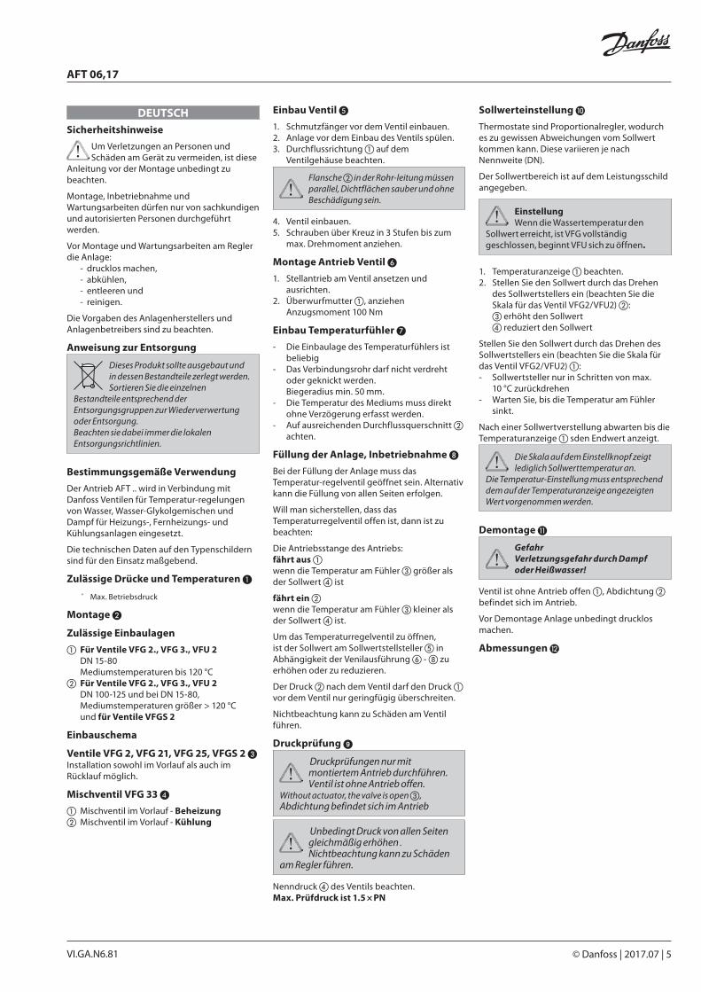
Einbau Ventil ❺
1. Schmutzfänger vor dem Ventil einbauen.2. Anlage vor dem Einbau des Ventils spülen.3. Durchflussrichtung ① auf dem
Ventilgehäuse beachten.
Flansche ② in der Rohr-leitung müssen parallel, Dichtflächen sauber und ohne Beschädi gung sein.
4. Ventil einbauen.5. Schrauben über Kreuz in 3 Stufen bis zum
max. Drehmoment anziehen.
Montage Antrieb Ventil ❻
1. Stellantrieb am Ventil ansetzen und ausrichten.
2. Überwurfmutter ①, anziehen Anzugsmoment 100 Nm
Einbau Temperaturfühler ❼
- Die Einbaulage des Temperaturfühlers ist beliebig
- Das Verbindungsrohr darf nicht verdreht oder geknickt werden. Biegeradius min. 50 mm.
- Die Temperatur des Mediums muss direkt ohne Verzögerung erfasst werden.
- Auf ausreichenden Durchflussquerschnitt ② achten.
Füllung der Anlage, Inbetriebnahme ❽
Bei der Füllung der Anlage muss das Temperatur-regelventil geöffnet sein. Alternativ kann die Füllung von allen Seiten erfolgen.
Will man sicherstellen, dass das Temperaturregelventil offen ist, dann ist zu beachten:
Die Antriebsstange des Antriebs:fährt aus ① wenn die Temperatur am Fühler ③ größer als der Sollwert ④ ist
fährt ein ② wenn die Temperatur am Fühler ③ kleiner als der Sollwert ④ ist.
Um das Temperaturregelventil zu öffnen, ist der Sollwert am Sollwertstellsteller ⑤ in Abhängigkeit der Venilausführung ⑥ - ⑧ zu erhöhen oder zu reduzieren.
Der Druck ② nach dem Ventil darf den Druck ① vor dem Ventil nur geringfügig überschreiten.
Nichtbeachtung kann zu Schäden am Ventil führen.
Druckprüfung ➒
Druckprüfungen nur mit montiertem Antrieb durchführen. Ventil ist ohne Antrieb offen.
Without actuator, the valve is open ③, Abdichtung befindet sich im Antrieb
Unbedingt Druck von allen Seiten gleichmäßig erhöhen . Nichtbeachtung kann zu Schäden
am Regler führen.
Nenndruck ④ des Ventils be achten. Max. Prüfdruck ist 1.5 × PN
Sollwerteinstellung ❿
Thermostate sind Proportionalregler, wodurch es zu gewissen Abweichungen vom Sollwert kommen kann. Diese variieren je nach Nennweite (DN).
Der Sollwertbereich ist auf dem Leistungsschild angegeben.
EinstellungWenn die Wassertemperatur den
Sollwert erreicht, ist VFG vollständig geschlossen, beginnt VFU sich zu öffnen.
1. Temperaturanzeige ① beachten.2. Stellen Sie den Sollwert durch das Drehen
des Sollwertstellers ein (beachten Sie die Skala für das Ventil VFG2/VFU2) ②:③ erhöht den Sollwert④ reduziert den Sollwert
Stellen Sie den Sollwert durch das Drehen des Sollwertstellers ein (beachten Sie die Skala für das Ventil VFG2/VFU2) ①:- Sollwertsteller nur in Schritten von max.
10 °C zurückdrehen- Warten Sie, bis die Temperatur am Fühler
sinkt.
Nach einer Sollwertverstellung abwarten bis die Temperaturanzeige ① sden Endwert anzeigt.
Die Skala auf dem Einstellknopf zeigt lediglich Sollwerttemperatur an.
Die Temperatur-Einstellung muss entsprechend dem auf der Temperaturanzeige angezeigten Wert vorgenommen werden.
Demontage ⓫
GefahrVerletzungsgefahr durch Dampf oder Heißwasser!
Ventil ist ohne Antrieb offen ①, Abdichtung ② befindet sich im Antrieb.
Vor Demontage Anlage unbedingt drucklos machen.
Abmessungen ⓬
6 | © Danfoss | 2017.07 VI.GA.N6.81
AFT 06,17
FRANCAISSécurité
Pour éviter des dommages physiques et matériels, il est absolument nécessaire de lire attentivement et de respecter ces
instructions avant le montage et la mise en service.
Le travail d’assemblage, de démarrage et de maintenance nécessaire doit être effectué uniquement par un personnel qualifié, formé et autorisé.
Avant le travail d’assemblage et de maintenance du contrôleur, le système doit être :
- dépressurisé- refroidi- vidé- nettoyé
Suivre les instructions du fabricant du système ou de son service.
Instructions d’élimination
Ce produit doit être démonté et ses composants doivent être triés, si possible, en différents groupes avant
recyclage ou élimination. Respectez toujours les réglementations locales en matière d’élimination de déchets.
Conditions d’utilisationLa tête thermostatique AFT... est utilisée en combinaison avec des vannes Danfoss, pour la régulation de la température de l’eau, de l’eau glycolée et de la vapeur pour chauffage, chauffage urbain et installations de réfrigération.
Les caractéristiques techniques indiquées sur la plaque signalétique sont déterminantes pour l’utilisation.
Pressions et températures autorisées ❶ * Pression de service max.
Montage ❷
Orientations de montage autorisées Pour vannes VFG2., VFG3., VFU2
DN 15-80 Température du fluide jusqu’à 120 °C
Pour vannes VFG2., VFG3., VFU2 DN 100-125 et pour DN 15-80, i la température du fluide est supérieure à > 120 °C
et vannes VFGS 2
Schéma de montage
vannes VFG2, VFG21, VFG25, VFGS2 ❸La vanne peut être montée sur l’aller ou sur le retour.
Vanne mélangeuse VFG 33 ❹① Vanne mélangeuse dans l’aller - Chauffage② Vanne mélangeuse dans l’aller -
Rafraîchissement
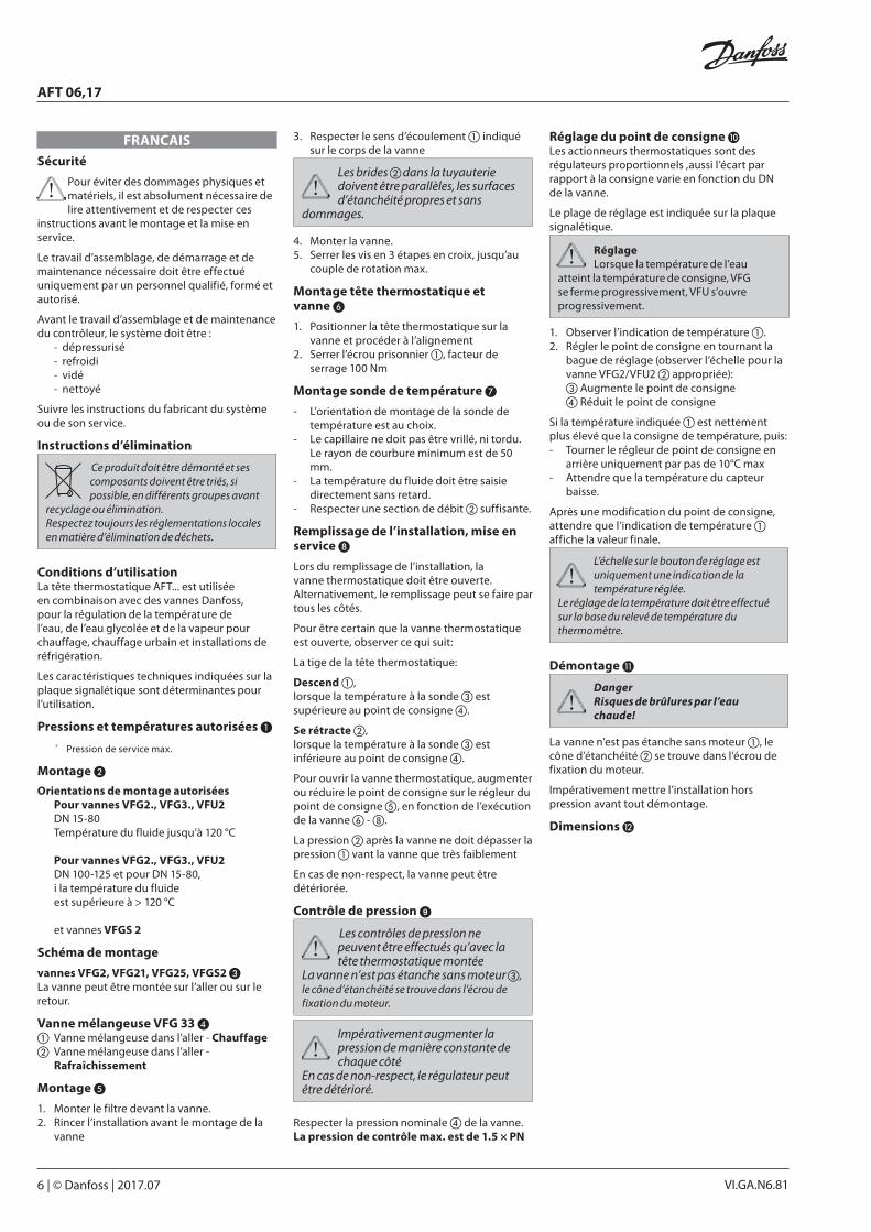
Montage ❺
1. Monter le filtre devant la vanne.2. Rincer l’installation avant le montage de la
vanne
3. Respecter le sens d’écoulement ① indiqué sur le corps de la vanne
Les brides ② dans la tuyauterie doivent être parallèles, les surfaces d’étanchéité propres et sans
dommages.
4. Monter la vanne.5. Serrer les vis en 3 étapes en croix, jusqu’au
couple de rotation max.
Montage tête thermostatique et vanne ❻
1. Positionner la tête thermostatique sur la vanne et procéder à l’alignement
2. Serrer l’écrou prisonnier ①, facteur de serrage 100 Nm
Montage sonde de température ❼
- L’orientation de montage de la sonde de température est au choix.
- Le capillaire ne doit pas être vrillé, ni tordu. Le rayon de courbure minimum est de 50 mm.
- La température du fluide doit être saisie directement sans retard.
- Respecter une section de débit ② suffisante.
Remplissage de l’installation, mise en service ❽
Lors du remplissage de l’installation, la vanne thermostatique doit être ouverte. Alternativement, le remplissage peut se faire par tous les côtés.
Pour être certain que la vanne thermostatique est ouverte, observer ce qui suit:
La tige de la tête thermostatique:
Descend ①,lorsque la température à la sonde ③ est supérieure au point de consigne ④.
Se rétracte ②,lorsque la température à la sonde ③ est inférieure au point de consigne ④.
Pour ouvrir la vanne thermostatique, augmenter ou réduire le point de consigne sur le régleur du point de consigne ⑤, en fonction de l’exécution de la vanne ⑥ - ⑧.
La pression ② après la vanne ne doit dépasser la pression ① vant la vanne que très faiblement
En cas de non-respect, la vanne peut être détériorée.
Contrôle de pression ➒
Les contrôles de pression ne peuvent être effectués qu’avec la tête thermostatique montée
La vanne n’est pas étanche sans moteur ③, le cône d’étanchéité se trouve dans l’écrou de fixation du moteur.
Impérativement augmenter la pression de manière constante de chaque côté
En cas de non-respect, le régulateur peut être détérioré.
Respecter la pression nominale ④ de la vanne.La pression de contrôle max. est de 1.5 × PN
Réglage du point de consigne ❿Les actionneurs thermostatiques sont des régulateurs proportionnels ,aussi l’écart par rapport à la consigne varie en fonction du DN de la vanne.
Le plage de réglage est indiquée sur la plaque signalétique.
RéglageLorsque la température de l’eau
atteint la température de consigne, VFG se ferme progressivement, VFU s’ouvre progressivement.
1. Observer l’indication de température ①.2. Régler le point de consigne en tournant la
bague de réglage (observer l’échelle pour la vanne VFG2/VFU2 ② appropriée):③ Augmente le point de consigne④ Réduit le point de consigne
Si la température indiquée ① est nettement plus élevé que la consigne de température, puis:- Tourner le régleur de point de consigne en
arrière uniquement par pas de 10°C max- Attendre que la température du capteur
baisse.
Après une modification du point de consigne, attendre que l’indication de température ① affiche la valeur finale.
L’échelle sur le bouton de réglage est uniquement une indication de la température réglée.
Le réglage de la température doit être effectué sur la base du relevé de température du thermomètre.
Démontage ⓫
DangerRisques de brûlures par l’eau chaude!
La vanne n’est pas étanche sans moteur ①, le cône d’étanchéité ② se trouve dans l’écrou de fixation du moteur.
Impérativement mettre l’installation hors pression avant tout démontage.
Dimensions ⓬
© Danfoss | 2017.07 | 7VI.GA.N6.81
AFT 06,17
POLSKIWarunki bezpieczeństwa
W celu uniknięcia zranienia osób i uszkodzenia urządzeń należy bezwzględnie przed montażem i
uruchomieniem zaworu zapoznać się dokładnie z niniejszą instrukcją.
Czynności związane z montażem, uruchomieniem i obsługą mogą być dokonywane wyłącznie przez osoby uprawnione i odpowiednio wykwalifikowane.
Przed montażem i obsługą konserwacyjną regulatora należy:
- zrzucić ciśnienie,- ostudzić urządzenie,- opróżnić układ,- oczyścić.
Prosimy stosować się do instrukcji producenta lub operatora układu.
Instrukcja dotycząca utylizacji
Ten produkt powinien być rozebrany a jego komponenty posegregowane, jeśli to możliwe, na różne grupy przed
poddaniem recyklingowi lub utylizacji. Zawsze stosuj się do miejscowych przepisów w zakresie usuwania odpadów.
Zakres zastosowańNapęd AFT jest stosowany w połączeniu z zaworami firmy Danfoss. Znajdują zastosowanie w regulacji temperatury wody, roztworu woda – glikol i pary wodnej w układach grzewczych, instalacjach sieci cieplnych i chłodzenia.
Dane techniczne na tabliczce znamionowej określają możliwości stosowania.
Dopuszczalne ciśnienia i temperatury ❶ * Max. ciśnienie robocze
Montaż ❷
Dopuszczalne pozycje montażu Dla zaworów VFG 2., VFG 3., VFU 2 DN 15-80 Temperatura czynnika do 120 °C
Dla zaworów VFG 2., VFG 3., VFU 2 DN 100-125 i dla DN 15-80,
temperatura czynnika powyżej 120 0C Zawory VFGS 2
Schemat instalacyjny
zaworów VFG 2(1), VFGS 2, VFU ❸
Montaż na rurociągu zasilającym lub powrotnym.
Zawory mieszające VFG 33 ❹① Zawór mieszający na rurociągu zasilającym -
Ogrzewanie② Zawór mieszający na rurociągu powrotnym -
Chłodzenie
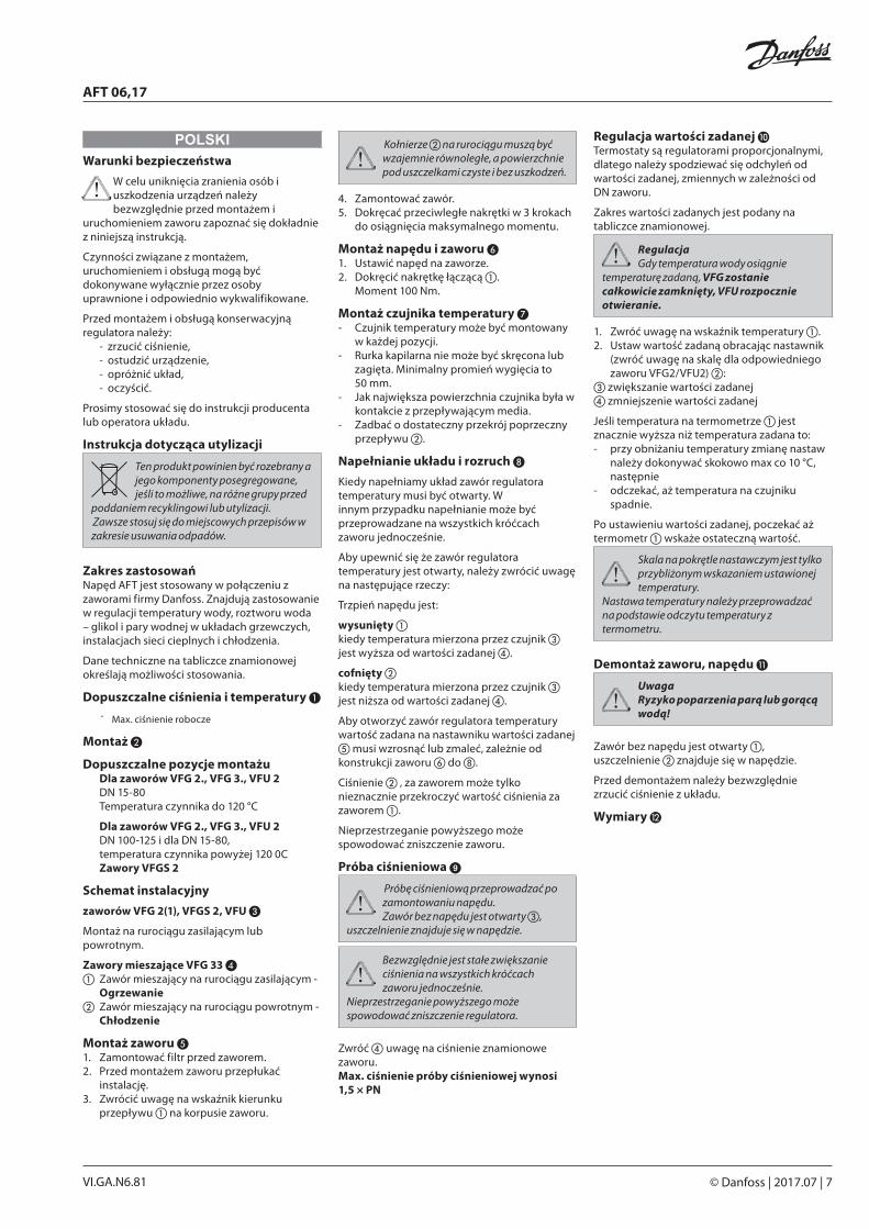
Montaż zaworu ❺1. Zamontować filtr przed zaworem.2. Przed montażem zaworu przepłukać
instalację.3. Zwrócić uwagę na wskaźnik kierunku
przepływu ① na korpusie zaworu.
Kołnierze ② na rurociągu muszą być wzajemnie równoległe, a powierzchnie pod uszczelkami czyste i bez uszkodzeń.
4. Zamontować zawór.5. Dokręcać przeciwległe nakrętki w 3 krokach
do osiągnięcia maksymalnego momentu.
Montaż napędu i zaworu ❻1. Ustawić napęd na zaworze.2. Dokręcić nakrętkę łączącą ①.
Moment 100 Nm.
Montaż czujnika temperatury ❼- Czujnik temperatury może być montowany
w każdej pozycji.- Rurka kapilarna nie może być skręcona lub
zagięta. Minimalny promień wygięcia to 50 mm.
- Jak największa powierzchnia czujnika była w kontakcie z przepływającym media.
- Zadbać o dostateczny przekrój poprzeczny przepływu ②.
Napełnianie układu i rozruch ❽
Kiedy napełniamy układ zawór regulatora temperatury musi być otwarty. W innym przypadku napełnianie może być przeprowadzane na wszystkich króćcach zaworu jednocześnie.
Aby upewnić się że zawór regulatora temperatury jest otwarty, należy zwrócić uwagę na następujące rzeczy:
Trzpień napędu jest:
wysunięty ①kiedy temperatura mierzona przez czujnik ③ jest wyższa od wartości zadanej ④.
cofnięty ②kiedy temperatura mierzona przez czujnik ③ jest niższa od wartości zadanej ④.
Aby otworzyć zawór regulatora temperatury wartość zadana na nastawniku wartości zadanej ⑤ musi wzrosnąć lub zmaleć, zależnie od konstrukcji zaworu ⑥ do ⑧.
Ciśnienie ② ‚ za zaworem może tylko nieznacznie przekroczyć wartość ciśnienia za zaworem ①.
Nieprzestrzeganie powyższego może spowodować zniszczenie zaworu.
Próba ciśnieniowa ➒
Próbę ciśnieniową przeprowadzać po zamontowaniu napędu.Zawór bez napędu jest otwarty ③,
uszczelnienie znajduje się w napędzie.
Bezwzględnie jest stałe zwiększanie ciśnienia na wszystkich króćcach zaworu jednocześnie.
Nieprzestrzeganie powyższego może spowodować zniszczenie regulatora.
Zwróć ④ uwagę na ciśnienie znamionowe zaworu. Max. ciśnienie próby ciśnieniowej wynosi 1,5 × PN
Regulacja wartości zadanej ❿Termostaty są regulatorami proporcjonalnymi, dlatego należy spodziewać się odchyleń od wartości zadanej, zmiennych w zależności od DN zaworu.
Zakres wartości zadanych jest podany na tabliczce znamionowej.
RegulacjaGdy temperatura wody osiągnie
temperaturę zadaną, VFG zostanie całkowicie zamknięty, VFU rozpocznie otwieranie.
1. Zwróć uwagę na wskaźnik temperatury ①.2. Ustaw wartość zadaną obracając nastawnik
(zwróć uwagę na skalę dla odpowiedniego zaworu VFG2/VFU2) ②:
③ zwiększanie wartości zadanej④ zmniejszenie wartości zadanej
Jeśli temperatura na termometrze ① jest znacznie wyższa niż temperatura zadana to:- przy obniżaniu temperatury zmianę nastaw
należy dokonywać skokowo max co 10 °C, następnie
- odczekać, aż temperatura na czujniku spadnie.
Po ustawieniu wartości zadanej, poczekać aż termometr ① wskaże ostateczną wartość.
Skala na pokrętle nastawczym jest tylko przybliżonym wskazaniem ustawionej temperatury.
Nastawa temperatury należy przeprowadzać na podstawie odczytu temperatury z termometru.
Demontaż zaworu, napędu ⓫
UwagaRyzyko poparzenia parą lub gorącą wodą!
Zawór bez napędu jest otwarty ①, uszczelnienie ② znajduje się w napędzie.
Przed demontażem należy bezwzględnie zrzucić ciśnienie z układu.
Wymiary ⓬
8 | © Danfoss | DHS-SRMT/SI | 2017.07 73696090 / VI.GA.N6.81
Danfoss can accept no responsibility for possible errors in catalogues, brochures and other printed material. Danfoss reserves the right to alter its products without notice. This also applies to products already on order provided that such alterations can be made without subsequential changes being necessary eady agreed.All trademarks in this material are property of the respective companies. Danfoss and the Danfoss logotype are trademarks of Danfoss A/S. All rights reserved.
AFT 06,17
HRVATSKISigurnosne napomene
Radi izbjegavanja ozljeda i oštećenja uređaja, prije montaže i stavljanja u pogon svakako pozorno pročitajte i
poštujte ove upute.
Montažu, stavljanje u pogon i održavanje smiju obaviti samo ovlaštene, školovane i kvalificirane osobe.
Prije montaže i održavanja pogona sustav je potrebno:
- rastlačiti - ohladiti- isprazniti- očistiti
Poštujte upute proizvođača i vlasnika sustava.
Upute za zbrinjavanje
Opremu koja sadrži elektroničke komponente nije dozvoljeno bacati u kućni otpad.
Potrebno ju je zbrinjavati odvojeno, s ostalim električnim i elektroničkim otpadom u skladu s odredbama lokalnog zakonodavstva.
Namjenska upotreba Pogon AFT.. upotrebljava se u kombinaciji s Danfossovim ventilima za regulaciju temperature vode, smjesa vode i glikola te pare u sustavima grijanja, daljinskog grijanja i hlađenja.
Tehnički podaci na označnim pločicama određuju upotrebu.
Dopušteni tlakovi i temperature ❶ * Maks. radni tlak
Montaža ❷
Dopušteni položaji ugradnje Za ventile VFG 2., VFG 3., VFU 2 DN 15-80 temperature medija do 120 °C Za ventile VFG 2., VFG 3., VFU 2 DN 100-125 i za DN 15-80, temperature medija > 120 °C i ventile VFGS 2
Shema ugradnje
Ventili VFG 2(1), VFGS 2, VFU ❸
Moguća ugradnja u polaz ili povrat.
Ventil za miješanje VFG 33 ❹① Ventil za miješanje u polazu - Grijanje② Ventil za miješanje u polazu - Hlađenje
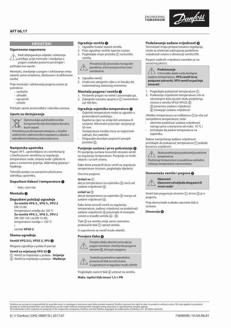
Ugradnja ventila ❺1. Ugradite hvatač ispred ventila.2. Prije ugradnje ventila isperite sustav.3. Pogledajte smjer protoka ① na kućištu
ventila.
Prirubnice ② cjevovodu moraju biti paralelne, a brtvene površine čiste i neoštećene.
4. Ugradite ventil. 5. Unakrsno zategnite vijke u tri koraka do
maksimalnog zateznog momenta.
Montaža pogona i ventila ❻1. Postavite pogon na ventil i poravnajte ga.2. Zategnite navojnu spojnicu ① momentom
od 100 Nm.
Ugradnja osjetnika temperature ❼- Osjetnik temperature može se ugraditi u
proizvoljnom položaju. - Kapilarna cijev ne smije biti omotana ili
savijena. Minimalni polumjer savijanja je 50 mm.
- Temperatura medija mora se registrirati odmah, bez zadrške.
- Osigurajte dovoljan poprečni presjek protoka ②.
Punjenje sustava i prvo pokretanje ❽Pri punjenju sustava mora biti otvoren ventil za regulaciju temperature. Punjenje se može obaviti i sa svih strana.
Kako biste provjerili da je ventil za regulaciju temperature otvoren, pogledajte sljedeće:
Osovina pogona:
izvlači se ①ako je temperatura na osjetniku ③ iveća od zadane vrijednosti ④.
uvlači se ②ako je temperatura na osjetniku ③ manja od zadane vrijednosti ④.
Kako biste otvorili ventil za regulaciju temperature, zadanu vrijednost na podešivači zadane vrijednosti ⑤ povećajte ili smanjite, ovisno o izvedbi ventila ⑥ - ⑧.
Tlak ② iza ventila smije samo neznatno prekoračiti tlak ① ispred ventila.
U suprotnom se ventil može oštetiti.
Provjera tlaka ➒
Provjeru tlaka obavite samo ako je pogon montiran. Ventil je bez pogona otvoren ③, brtva je u pogonu.
Svakako je potrebno neprekidno povećavati tlak sa svih strana.U suprotnom se regulator može oštetiti.
Pogledajte nazivni tlak ④ utisnut na ventilu.
Maks. ispitni tlak iznosi 1,5 × PN
Podešavanje zadane vrijednosti ❿Termostati imaju proporcionalnu regulaciju, može se očekivati odstupanje podešene vrijednosti ovisno o dimenziji ventila DN.
Raspon zadanih vrijednost naveden je na označnoj pločici.
PodešavanjeU trenutku kada voda dostigne
zadanu temperaturu, VFG ventil će se potpuno zatvoriti, VFU ventil se počinje otvarati.
1. Pogledajte pokazivač temperature ①.2. Podešenje vrijednosti temperature vrši se
okretanjem kola (pratiti skalu podešenja, ovisno o ventilu VFG2/VFU2) ②:
③ povećava zadanu vrijednost ④ smanjuje zadanu vrijednost
Ukoliko temperatura na indikatoru ① je viša od namještene temperature, tada: - okrenite podešivač zadane vrijednosti
natrag samo u koracima od maks. 10 °C i- pričekajte da padne temperatura na
osjetniku.
Nakon namještanja zadane vrijednosti pričekajte da pokazivač temperature ① pokaže konačnu vrijednost.
Skala podešenja je pokazatelj podešene temperature.
Podešenje temperature se podešava sukladno očitanju temperature s termometra.
Demontaža ventila i pogona ⓫
OpasnostOpasnost od ozljeda zbog pare ili vruće vode!
Ventil bez pogona je otvoren ①, brtva ② je u pogonu.
Prije demontaže svakako ispustite tlak iz sustava.
Dimenzije ⓬