online and offline identification of tyre model parameters · the thesis also investigates the...
TRANSCRIPT

THESIS FOR THE DEGREE OF DOCTOR OF PHILOSOPHY
Online and Offline Identification of Tyre Model Parameters
Anton Albinsson
Department of Mechanics and Maritime Sciences
CHALMERS UNIVERSITY OF TECHNOLOGY
Gothenburg, Sweden 2018

Online and Offline Identification of Tyre Model Parameters ANTON ALBINSSON ISBN 978-91-7597-720-1 © ANTON ALBINSSON, 2018 Doktorsavhandlingar vid Chalmers tekniska högskola Ny serie nr 4401 ISSN 0346-718X Department of Mechanics and Maritime Sciences Chalmers University of Technology SE-412 96 Gothenburg Sweden Telephone +46 (0)31 772 1000 Cover: CraigTumblison (https://commons.wikimedia.org/wiki/File:Ice_on_Tire.jpg), „Ice on Tire“, https://creativecommons.org/licenses/by-sa/3.0/legalcode Chalmers Reproservice Gothenburg, Sweden 2018

i
“The tyre is under no obligation to make sense to you.”
– Freely interpreted and modified quote from Neil deGrasse Tyson

ii
iii
Online and Offline Identification of Tyre Model Parameters ANTON ALBINSSON Department of Mechanics and Maritime Sciences Chalmers University of Technology
ABSTRACT The accelerating development of active safety system and autonomous vehicles put higher requirements on both environmental sensing and vehicle state estimation as well as virtual verification of these systems. The tyres are relevant in this context due to the considerable influence of the tyres on the vehicle motion and the performance boundaries set by the tyres. All forces that the driver use to control the vehicle are generated in the contact patch between the tyre and the road on a normal passenger car. Hence, the performance limits imposed by the tyres should ideally be considered in the active safety systems and in self-driving vehicles. Due to tyres influence on the vehicle motions, they are some of the key components that must be accurately modelled to correlate complete vehicle simulations models with physical testing.
This thesis investigates the possibility to estimate the tyre-road friction coefficient during normal driving using active tyre force excitation, i.e. online identification of tyre model parameters. The thesis also investigates the possibility to scale tyre Force and Moment (F&M) models for complete vehicle simulations from indoor tests to real road surfaces using vehicle-based tyre testing, i.e. offline identification of tyre model parameters.
For online identification of tyre model parameters, the focus has been on how to perform tyre force excitation to maximize the information about the tyre-road friction coefficient. Furthermore, the required excitation level, as a ratio of the maximum tyre-road friction coefficient, for different road surfaces and tyre models have been evaluated for a larger number of passenger car tyres. The thesis shows the feasibility and benefits of using active tyre force excitations and illustrates its benefits when estimating the tyre-road friction coefficient by identifying nonlinear tyre model parameters. The method shows promising results by offering tyre-road friction estimates when demanded by the driver or an on-board system. This system can also be combined with other tyre-road friction estimates to offer a continuous tyre-road friction estimate, e.g. through car-to-car communication.
For offline identification of tyre model parameters, the focus was put on rescaling tyre models from indoor testing to a real-world road surface using vehicle-based tyre testing. Sensors were fitted to the vehicle to measure all inputs and outputs of the Pacejka 2002 tyre model. Furthermore, testing was performed on both different road surfaces and using different manoeuvres for tyre model identification. The effect on the complete vehicle behaviour in simulation when using tyre models based on different manoeuvres and road surfaces was investigated. The results show the importance of using a road surface and manoeuvre that are representative for the road surface and manoeuvre in which the vehicle will be evaluated. The sensitivity to different manoeuvres are mainly related to the changes in tyre properties with tyre surface temperature and the lack of temperature effects in the tyre model. The method shows promising results as an efficient way to rescale tyre models to a new road surface.
Keywords: state estimation, vehicle dynamics, tyre-road friction estimation, active safety, parameter estimation, tyre testing, simulation, computer aided engineering

iv
v
ACKNOWLEDGEMENTS
The work presented in this thesis has been funded by the Fordonstrategisk Forskning och Innovation (FFI) program of Vinnova. Three external partners have also been involved in the projects, Volvo Car Group, VTI and & BorgWarner TorqTransfer Systems AB. Their support during the thesis has been greatly appreciated.
I would especially like to thank my main supervisor Fredrik Bruzelius for his excellent support and guidance during the thesis work. Our weekly discussions have given me a lot of invaluable insights on all levels that greatly improved the quality of the work and helped my personal development. I would also like to thank my Co-supervisors Bengt Jacobson and Jonas Fredriksson for their support during my time at Chalmers. A special thanks to Bengt Jacobson for his good high and low-level questions regarding the project and the articles.
Thanks to Mats Jonasson from Volvo Cars for his interest and great support in the TorqSens project related to this thesis. I would also like to thank Tony Gustafsson for his good advice and interest in the TorqSens project, your knowledge within signal processing has been very valuable. From BorgWarner I would like to thank Pierre Pettersson for always answering the questions I had regarding electric propulsion and for finding time to support the project.
Related to the second project TyreSens, I would like to thank Shenhai Ran, Max Boerboom and Egbert Bakker from Volvo Cars for their support during the project. Furthermore, I would like to thank Matthijs Klomp for supporting the application process of the TyreSens project.
I would also like to thank my current and former co-workers in the Vehicle Dynamics group at Chalmers, Adithya, Artem, Derong, Gunnar, Ingemar, Jonathan, Kristoffer, Leo, Manjurul, Ola, Peter, Pär, Sixten, Toheed, Tushar, Ulrich and Weitao for the interesting discussions and the sublime working environment. A special thanks to Mathias Lidberg for getting me into the path of vehicle dynamics. Thanks to Sonja, Britta and Marianne for their great administrative work during my time at Chalmers.
Finally, I would like to thank my family and friends for supporting and encouraging me during this work. Special thanks to Louise for her love during the writing of this thesis.

vi

vii
THESIS This thesis is based on the work contained in the following papers, presented below in chronological order. In the thesis, the papers will be referred to by their respective letter.
A. Albinsson, A., Bruzelius, F., Jacobson, B., & Jonasson, M. (2014). Tire Force Estimation Utilizing Wheel Torque Measurements and Validation in Simulations and Experiments. In The 12th International Symposium on Advanced Vehicle Control, (AVEC’14), Tokyo, Japan.
B. Albinsson, A., Bruzelius, F., Pettersson, P., Jonasson, M., & Jacobson, B. (2016). Estimation of the inertial parameters of vehicles with electric propulsion. Proceedings of the Institution of Mechanical Engineers, Part D: Journal of Automobile Engineering, 230(9), 1155-1172.
C. Albinsson, A., Bruzelius, F., Gustafsson T., Jonasson, M. & Jacobson, B (2015). Identification of tyre characteristics using active force excitation. In The 24th International Symposium on Dynamics of Vehicles on Roads and Tracks (IAVSD’15), Graz, Austria.
D. Albinsson, A., Bruzelius, F., Jacobson, B. (2016). Friction utilization for tyre-road friction estimation on snow: an experimental study. In The 13th International Symposium on Advanced Vehicle Control, (AVEC’16), Munich, Germany
E. Albinsson, A., Bruzelius, F., Jacobson, B., & Fredriksson, J. (2017). Design of tyre force excitation for tyre–road friction estimation. Vehicle System Dynamics, 55(2), 208-230.
F. Prokeš, J. Albinsson, A. & Laine, L. (2016). Quantification of Excitation Required for Accurate Friction Estimation. IEEE 19th International Conference on Intelligent Transportation Systems (ITSC), Rio de Janeiro, Brazil, pp. 2551-2558.
G. Albinsson, A., Bruzelius, F., Hjort, M. (2017). Required friction utilization for tyre-road friction estimation on wet asphalt: an experimental study. In The 25th International Symposium on Dynamics of Vehicles on Roads and Tracks (IAVSD’27), Rockhampton, Australia.
H. Albinsson, A., Bruzelius, F., Els, P.S., Jacobson, B., Bakker, E. (2017), Lateral Tire vibration considerations in vehicle based tyre testing. Presented at the 36th annual meeting of The Tire Society, Akron, Ohio, USA, Accepted for publication in Tire Science and Technology.
I. Albinsson, A., Bruzelius, F., Jacobson, B., Bakker, E. (2018), Evaluation of vehicle based tyre testing methods. Accepted for publication in Proceedings of the Institution of Mechanical Engineers Part D -Journal of automobile engineering, special issue on “Tyre modelling and technology”
viii
J. Albinsson, A., Bruzelius, F., Jacobson, B., Bakker, E. (2018), Validation of vehicle based tyre testing methods. Submitted for publication in Proceedings of the Institution of Mechanical Engineers Part D -Journal of automobile engineering, special issue on “Tyre modelling and technology”
The author of this thesis had the main responsibility for designing and writing the estimator algorithms, performing simulations, analysing the results and writing the papers for all paper except for paper F. The experiments in Paper B and C were conducted by the author together with some of the co-authors. The experiments in paper D, E, G were done by VTI and the author did not conduct the experiments in paper A. The author did not write paper F but had a significant role in the development of the method and analysis of the results in the role as a supervisor for the first author.
Other relevant publications not included in the thesis:
I. Jonasson, M., Gustafsson, T., Albinsson, A., Bruzelius, F. (2016), Method and arrangement for tire to road friction estimation, Patent application number EP20150172369.
II. Jonasson, M., Albinsson, A., Bruzelius, F. (2017), Friction estimation and wheel slip control arrangement by gradient seeking method. Patent application number EP171692296.
ix
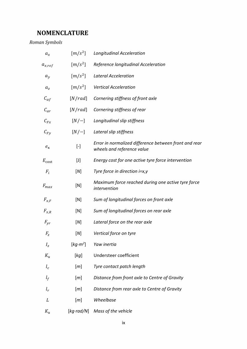
NOMENCLATURE Roman Symbols
𝑎𝑎𝑥𝑥 [𝑚𝑚/𝑠𝑠2] Longitudinal Acceleration
𝑎𝑎𝑥𝑥,𝑟𝑟𝑟𝑟𝑟𝑟 [𝑚𝑚/𝑠𝑠2] Reference longitudinal Acceleration
𝑎𝑎𝑦𝑦 [𝑚𝑚/𝑠𝑠2] Lateral Acceleration
𝑎𝑎𝑧𝑧 [𝑚𝑚/𝑠𝑠2] Vertical Acceleration
𝐶𝐶𝛼𝛼𝑟𝑟 [𝑁𝑁/𝑟𝑟𝑎𝑎𝑟𝑟] Cornering stiffness of front axle
𝐶𝐶𝛼𝛼𝑟𝑟 [𝑁𝑁/𝑟𝑟𝑎𝑎𝑟𝑟] Cornering stiffness of rear
𝐶𝐶𝐹𝐹𝑥𝑥 [𝑁𝑁/−] Longitudinal slip stiffness
𝐶𝐶𝐹𝐹𝑦𝑦 [𝑁𝑁/−] Lateral slip stiffness
𝑒𝑒κ [-] Error in normalized difference between front and rear wheels and reference value
𝐸𝐸cost [J] Energy cost for one active tyre force intervention
𝐹𝐹𝑖𝑖 [N] Tyre force in direction i=x,y
𝐹𝐹𝑚𝑚𝑚𝑚𝑥𝑥 [N] Maximum force reached during one active tyre force intervention
𝐹𝐹𝑥𝑥,𝐹𝐹 [N] Sum of longitudinal forces on front axle
𝐹𝐹𝑥𝑥,𝑅𝑅 [N] Sum of longitudinal forces on rear axle
𝐹𝐹𝑦𝑦𝑟𝑟 [N] Lateral force on the rear axle
𝐹𝐹𝑧𝑧 [N] Vertical force on tyre
𝐼𝐼𝑧𝑧 [kg∙m2] Yaw inertia
𝐾𝐾𝑢𝑢 [kg] Understeer coefficient
𝑙𝑙𝑐𝑐 [m] Tyre contact patch length
𝑙𝑙𝑟𝑟 [m] Distance from front axle to Centre of Gravity
𝑙𝑙𝑟𝑟 [m] Distance from rear axle to Centre of Gravity
𝐿𝐿 [m] Wheelbase
𝐾𝐾𝑢𝑢 [kg∙rad/N] Mass of the vehicle

x
𝑅𝑅𝑐𝑐𝑢𝑢𝑟𝑟𝑐𝑐𝑟𝑟 [m] Curve Radius
𝑅𝑅𝑟𝑟 [m] Tyre effective rolling radius
𝑅𝑅𝐿𝐿 [m] Tyre loaded radius
𝑡𝑡𝑐𝑐 [s] Time before the entire contact patch is replaced
𝑡𝑡𝑖𝑖𝑖𝑖𝑖𝑖 [s] Time for one active tyre force excitation
𝑣𝑣𝑥𝑥 [𝑚𝑚/𝑠𝑠] Longitudinal velocity of the vehicle centre of gravity
𝑣𝑣𝑥𝑥 ,𝑐𝑐 [𝑚𝑚/𝑠𝑠] Longitudinal velocity of wheel centre
𝑣𝑣𝑦𝑦,𝑐𝑐 [𝑚𝑚/𝑠𝑠] Lateral velocity of wheel centre
𝑣𝑣𝑦𝑦,𝑐𝑐 [𝑚𝑚/𝑠𝑠] Vertical velocity of wheel centre
𝑣𝑣𝑥𝑥,𝑟𝑟𝑟𝑟𝑟𝑟 [𝑚𝑚/𝑠𝑠] Reference value for longitudinal velocity of the vehicle centre of gravity
𝑉𝑉 [𝑚𝑚/𝑠𝑠] Vehicle speed
𝑇𝑇𝐵𝐵 [Nm] Total brake torque
𝑇𝑇𝑏𝑏𝑟𝑟𝑚𝑚𝑏𝑏𝑟𝑟,𝑟𝑟𝑟𝑟𝑚𝑚𝑟𝑟 [Nm] Brake Torque request to rear friction brakes
𝑇𝑇𝑑𝑑𝑟𝑟𝑖𝑖𝑐𝑐𝑟𝑟𝑟𝑟,𝑟𝑟𝑟𝑟𝑟𝑟𝑢𝑢𝑟𝑟𝑟𝑟𝑖𝑖 [Nm] Driver requested propulsion torque request
𝑇𝑇𝑟𝑟𝑖𝑖𝑒𝑒𝑖𝑖𝑖𝑖𝑟𝑟,𝑟𝑟𝑟𝑟𝑓𝑓𝑖𝑖𝑖𝑖 [Nm] Propulsion torque request to internal combustion engine, front axle
𝑇𝑇𝐸𝐸𝐸𝐸 [Nm] Propulsion Torque from Electric Motor
𝑇𝑇𝐼𝐼𝐼𝐼𝐸𝐸 [Nm] Propulsion Torque from Internal Combustion Engine
𝑋𝑋 [𝑚𝑚] Global Position X
𝑌𝑌 [𝑚𝑚] Global Position Y
Greek Symbols
𝛼𝛼 [rad] Tyre slip angle
𝛿𝛿 [𝑟𝑟𝑎𝑎𝑟𝑟] Steering angle of the front wheels
𝛿𝛿𝑆𝑆𝑆𝑆𝑆𝑆 [𝑟𝑟𝑎𝑎𝑟𝑟] Steering wheel angle
𝜂𝜂𝑒𝑒𝑟𝑟𝑚𝑚𝑟𝑟 [-] Gear ratio

xi
𝜅𝜅Δ [-] Maximum normalized wheel speed difference between front and rear wheels
κΔ𝑙𝑙 [-] Normalized wheel speed difference between front and rear wheels, left side
κΔ𝑟𝑟 [-] Normalized wheel speed difference between front and rear wheels, right side
𝜆𝜆𝜇𝜇 [-] Scaling factor for maximum tyre-road friction coefficient in Pacejka 2002 model.
𝜇𝜇𝑖𝑖,𝑚𝑚𝑚𝑚𝑥𝑥 [-] Tyre-road friction coefficient in direction i=x,y
𝜎𝜎𝑥𝑥 [-] Longitudinal slip ratio
𝜎𝜎𝑦𝑦 [-] Lateral slip ratio
𝜙𝜙𝑥𝑥 [𝑟𝑟𝑎𝑎𝑟𝑟] Roll angle of the vehicle
𝜙𝜙𝑦𝑦 [𝑟𝑟𝑎𝑎𝑟𝑟] Pitch angle of the vehicle
𝜙𝜙𝑧𝑧 [𝑟𝑟𝑎𝑎𝑟𝑟] Course Angle of the vehicle
𝜔𝜔𝐸𝐸𝐸𝐸 [𝑟𝑟𝑎𝑎𝑟𝑟/𝑠𝑠] Electric Motor Speed
𝜔𝜔𝐼𝐼𝐼𝐼𝐸𝐸 [𝑟𝑟𝑎𝑎𝑟𝑟/𝑠𝑠] Engine Speed
𝜔𝜔𝑤𝑤𝑖𝑖 [𝑟𝑟𝑎𝑎𝑟𝑟/𝑠𝑠] Wheel speed on each wheel
𝜔𝜔 [𝑟𝑟𝑎𝑎𝑟𝑟/𝑠𝑠] Wheel angular velocity
𝜔𝜔𝑥𝑥 [𝑟𝑟𝑎𝑎𝑟𝑟/𝑠𝑠] Roll angular velocity
𝜔𝜔𝑦𝑦 [𝑟𝑟𝑎𝑎𝑟𝑟/𝑠𝑠] Pitch angular velocity
𝜔𝜔𝑧𝑧 [𝑟𝑟𝑎𝑎𝑟𝑟/𝑠𝑠] Yaw angular velocity

xii

xiii
CONTENTS ABSTRACT ....................................................................................................................................................... III
ACKNOWLEDGEMENTS .................................................................................................................................... V
THESIS ............................................................................................................................................................ VII
NOMENCLATURE ............................................................................................................................................. IX
CONTENTS ..................................................................................................................................................... XIII
1. INTRODUCTION ....................................................................................................................................... 1
1.1. RESEARCH LIMITATIONS ........................................................................................................................ 3 1.2. CONTRIBUTION OF THIS THESIS................................................................................................................ 3 1.3. THESIS OUTLINE .................................................................................................................................. 4
2. TYRE MODELLING FUNDAMENTALS ........................................................................................................ 5
2.1. IMPORTANCE FOR COMPLETE VEHICLE HANDLING SIMULATIONS ....................................................................... 9
3. ONLINE TYRE MODEL PARAMETER IDENTIFICATION ............................................................................. 11
3.1. FRICTION ESTIMATION STRATEGIES ......................................................................................................... 12 3.2. VEHICLE STATE AND PARAMETER ESTIMATION ........................................................................................... 13 3.3. TYRE MODELS FOR ONLINE IDENTIFICATION OF TYRE MODEL PARAMETERS ........................................................ 14 3.4. ACTIVE TYRE FORCE EXCITATION ............................................................................................................ 15 3.5. BASIC CONCEPT................................................................................................................................. 16 3.6. LIMITATIONS .................................................................................................................................... 17 3.7. TYRE MODELS FOR ACTIVE TYRE FORCE EXCITATION .................................................................................... 18 3.8. DIFFERENT STRATEGIES FOR TORQUE APPLICATION ..................................................................................... 18 3.9. IMPLEMENTED EXCITATION STRATEGIES ................................................................................................... 18
3.9.1. PID controller ........................................................................................................................... 19 3.9.2. Extremum-seeking algorithms .................................................................................................. 19
3.10. OTHER CONSIDERATIONS ..................................................................................................................... 22
4. OFFLINE TYRE MODEL PARAMETER IDENTIFICATION ............................................................................ 25
4.1. TYRE MODELS ................................................................................................................................... 26 4.2. STEADY-STATE MODELS ....................................................................................................................... 26 4.3. DYNAMIC TYRE MODELS ...................................................................................................................... 26 4.4. TYRE FORCE AND MOMENT MEASUREMENT .............................................................................................. 27 4.5. FLAT BELT TESTING MACHINE .............................................................................................................. 27 4.6. TYRE TESTING TRAILER/TRUCK............................................................................................................... 28 4.7. CAMBER RIDGE AND OTHER FACILITIES WITH CHANGEABLE ROAD SURFACES ...................................................... 29 4.8. VEHICLE-BASED TYRE TESTING ............................................................................................................... 29 4.9. INFLUENCE OF OPERATING CONDITIONS ................................................................................................... 30 4.10. INFLUENCE OF VEHICLE MANOEUVRE ...................................................................................................... 32
5. SUMMARY OF PAPERS .......................................................................................................................... 35
5.1. PAPER A - TIRE FORCE ESTIMATION UTILIZING WHEEL TORQUE MEASUREMENTS AND VALIDATION IN SIMULATIONS AND EXPERIMENTS ................................................................................................................................................. 35 5.2. PAPER B - ESTIMATION OF THE INERTIAL PARAMETERS OF VEHICLES WITH ELECTRIC PROPULSION ........................... 35 5.3. PAPER C - IDENTIFICATION OF TYRE CHARACTERISTICS USING ACTIVE FORCE EXCITATION ...................................... 35 5.4. PAPER D - FRICTION UTILIZATION FOR TYRE-ROAD FRICTION ESTIMATION ON SNOW: AN EXPERIMENTAL STUDY ......... 36 5.5. PAPER E - DESIGN OF TYRE FORCE EXCITATION FOR TYRE–ROAD FRICTION ESTIMATION ........................................ 36 5.6. PAPER F - QUANTIFICATION OF EXCITATION REQUIRED FOR ACCURATE FRICTION ESTIMATION ............................... 36 5.7. PAPER G - REQUIRED FRICTION UTILIZATION FOR TYRE-ROAD FRICTION ESTIMATION ON WET ASPHALT: AN EXPERIMENTAL STUDY 37 5.8. PAPER H - TIRE VIBRATION CONSIDERATIONS IN VEHICLE-BASED TYRE TESTING .................................................. 37
xiv
5.9. PAPER I - EVALUATION OF VEHICLE BASED TYRE TESTING METHODS ................................................................ 37 5.10. PAPER J - VALIDATION OF VEHICLE BASED TYRE TESTING METHODS ................................................................. 38
6. CONCLUSIONS ....................................................................................................................................... 39
6.1. ONLINE TYRE MODEL PARAMETER IDENTIFICATION ..................................................................................... 39 6.2. OFFLINE TYRE MODEL PARAMETER IDENTIFICATION ................................................................................... 40
7. FUTURE WORK AND RECOMMENDATIONS ........................................................................................... 41
REFERENCES ................................................................................................................................................... 43
PAPER A ........................................................................................................................................................... A
PAPER B ........................................................................................................................................................... B
PAPER C............................................................................................................................................................ C
PAPER D ........................................................................................................................................................... D
PAPER E ............................................................................................................................................................ E
PAPER F ............................................................................................................................................................ F
PAPER G ...........................................................................................................................................................G
PAPER H ........................................................................................................................................................... H
PAPER I.............................................................................................................................................................. I
PAPER J ............................................................................................................................................................. J

1
1. Introduction Every year, around 1.2 million people die in road traffic accidents around the world. In 2012, road traffic injuries were the leading cause of death among people aged 15-29. Furthermore, for every road traffic fatality, over 20 people sustain non-fatal injuries. In Europe, the risk of dying in a road traffic accident is smaller compared to the rest of the world and 51% of traffic-related deaths are car occupants, compared to 31% for the whole world (1). Hence, around 372,000 people die each year from injuries suffered as car occupants. Thus, improving the safety of passenger cars has strong potential to reduce the number of deaths in road traffic accidents around the world. Moreover, avoiding collisions between vulnerable road users and passenger cars (with active safety systems, for instance) can further reduce the number of road-traffic-related deaths.
Active safety systems and in particular vehicle dynamics control functions, such as Electronic Stability Control (ESC) and ABS (anti-lock braking system), have reduced the number of injuries and deaths in traffic accidents (2). The current trend is for modern vehicles to be equipped with a larger number of more sophisticated active safety systems, such as Automatic Emergency Braking (AEB), Lane Keeping Assist (LKA), Evasive Manoeuvre Assist (EMA) etc. (3). These systems require information about vehicle states, or surroundings or both. Some of these states can be easily obtained by direct measurements from sensors mounted on the vehicle. However, some states cannot be measured directly and need to be estimated from other sensor signals.
The evolution of active safety functions has led to a rapid development towards fully autonomous vehicles. SAE level 2 automated vehicles (4) are already operating on public roads and are sold as optional equipment (Volvo’s Pilot Assist 2, for example). At this level of automation, the driver is still expected to monitor their environment and intervene if necessary. At higher levels of automation, an automated driving system should monitor the driving environment with no support from the human driver. To classify environmental conditions as safe for automated driving, the system must know the performance limitations of the vehicle. This is directly related to tyre-road friction estimation and, consequently, online tyre model parameter identification. Autonomous vehicles also have the potential to reduce the number of traffic-related deaths and injuries, but their effectiveness depends on how good these systems can become in the future.
Physical testing still has a key role in today’s vehicle development process but is both expensive and time-consuming. Thus, the main reason for improving the accuracy of force and moment tyre models is to reduce development time and costs by enabling virtual development and verification of active safety systems. The trend towards replacing physical tests with simulations has already started in some vehicle applications and subsystems, such as brake software (5). Furthermore, a new proposal for ESC regulations (6) allows virtual homologation of vehicle variants through simulations, if the vehicle simulation models are accurate enough. Tyres are among the components which must be modelled accurately to achieve high levels of accuracy in the full vehicle simulation models. By having a more efficient development process for active safety systems, more resources can be expended on improving these systems. The performance of these systems could therefore be improved to further reduce traffic-related injuries and deaths.
The tyre, arguably one of the most vital components on a vehicle, is also the main component limiting the vehicle’s motion capabilities. On a normal passenger car, all forces used by the

2
driver to control the vehicle are transferred to the road through the tyres. Yet the contact patch of each tyre is roughly 150 cm2 at 2 bar inflation pressure (7), about the same size as a piece of A6 paper (1/4 A4) (8). The tyres limit the maximum deceleration or cornering velocity that a vehicle can achieve (see (9) for example). Hence, both drivers and active safety systems would benefit from knowing approximately how much force the tyres can generate at a given moment, in order to make appropriate control decisions. Tyres also affect the ride, steering and handling of the vehicle and must be modelled properly if these vehicle dynamics-related attributes are to be evaluated. Thus, tyres are among the most important components for accurate modelling when simulating a vehicle’s motion. This is directly related to offline tyre model parameter identification.
This thesis focuses mainly on two aspects relating to tyre modelling and tyre model parameter identification: 1) online tyre model parameter identification for active safety systems and 2) offline tyre model parameter identification for tyre modelling in full-vehicle steering and handling simulations. These topics are related using the basic problem of being able to describe the tyre force and moment generation mathematically. The main differences are in the limitations imposed by the various applications. Consequently, the complexity of the tyre model used and methods of identifying tyre model parameters differ between applications. Different problems are therefore encountered when investigating these two aspects of tyre model parameter identification. Many tyre models, especially force and moment models, have the interaction between tyre and road implicitly included. Hence, when referring to tyre models in the context of this thesis, the implication is that the tyre-road interaction is being modelled.
In online tyre model parameter identification, one of the main parameters of interest (and one of the most challenging to estimate accurately) is the maximum tyre-road friction coefficient. This parameter quantifies the maximum horizontal force that the tyre can generate for a given vertical load. The friction coefficient (and other tyre model parameters) varies for different road surfaces and conditions (10). Hence, when the vehicle has a travelled a short distance, the road surface may have changed and consequently also the tyre model parameters. The time available for identifying these parameters is therefore limited. Furthermore, the vehicle must follow the driver’s intended path and states. Hence, there is limited opportunity to change the vehicle motion to improve the estimate of tyre parameters. These are the main challenges addressed in this thesis, in relation to online tyre model parameter identification.
The tyre models used in offline parameter identification for full-vehicle steering and handling simulations are more complex than those used to identify tyre parameters online. The time available for the identification process is longer; normally limited only by cost and time. This means that manoeuvres and sensor equipment can be chosen which maximise opportunities to identify the unknown tyre parameters. Hence, in both cases, even if the basic idea of identifying unknown tyre model parameters remains, the actual implementation of the methods and focus of the identification process differs. The main difficulties with offline tyre model parameter identification are: understanding which type of tyre model to use and how to choose a testing procedure to maximise usable operating conditions for the identified model.
3
1.1. Research limitations This thesis does not attempt to develop the estimator algorithms themselves but rather to provide the models and prerequisites required for such estimation. Hence, the algorithms used for online and offline tyre model parameter identification can be found in existing literature.
Only tyre-model-based tyre parameter estimation methods are considered. In a real vehicle, the tyre-road friction information from several sources will likely be merged into one estimate per tyre. Thus, the active tyre force excitation methods presented in this study should not be thought of as the sole solution to tyre-road friction estimation, but as one source of information.
No comfort, noise, wear or efficiency aspects were considered or analysed for active tyre force excitation.
The sensors considered in the online tyre parametrisation are limited to those that it would reasonably be found on a premium production vehicle in 2020. For self-driving vehicles, the number and quality of sensors will be greater. However, even vehicles without self-driving capabilities should contribute tyre-road friction information.
The tyre model used in the offline tyre model parameter identification is limited to the Pacejka 2002 model. Hence, no temperature effects are considered and no new tyre models are developed.
Offline tyre model parameter identification focuses on handling simulations at low frequencies, where tyre relaxation can be ignored.
The investigation of vehicle-based tyre testing is mainly limited to the lateral tyre force characteristics. Hence, the parameters and scaling factors for longitudinal tyre force, aligning moment and effect of combined slip have not been identified.
The lateral tyre force vibrations investigated in Paper H are only investigated qualitatively. The suspension model used is simplified, to illustrate the effect that different operating conditions and suspension parameters have on the vibrations.
1.2. Contribution of this thesis • Investigation of how tyre forces and inertial parameters required for online tyre model
parameter identification can be estimated from the signals available in a production vehicle. The sensitivity of the tyre force estimates to vehicle parameters are investigated in Paper A while Paper B investigates the estimation error that can be expected when estimating the inertial parameters.
• Experimental investigation of active tyre force excitation and evaluation of different excitation strategies. It was shown in Paper C that the signals required for online tyre model parameter identification can be estimated from the signals available in a production vehicle and that the method can be used to reach sufficient excitation to estimate the tyre-road friction coefficient. Paper E investigated how the torque should be applied to a wheel to achieve a better estimate of the tyre-road friction coefficient for different tyre models and different road surfaces.
4
• Evaluation of the suitability of different tyre models on different road surfaces for friction estimation and the required friction utilisation for accurate friction estimation. These studies, in Papers D, F, G (and partly in Paper E) are important to understand how great an excitation is required when using active tyre force excitation, or any other method that uses the slip-force curve for online tyre model parameter identification.
• Evaluation of vehicle-based tyre testing and its potential for offline tyre model parameter identification for homologation of active safety systems. The possibility of using vehicle-based tyre testing to reparametrize tyre models from one road surface to another was investigated in Papers I and J. The influence of both the manoeuvre chosen and the road surface on the resulting tyre models (and consequently full vehicle simulation models) were also investigated, mainly in Paper J.
• Investigation of challenges related to operating conditions in tyre testing, in particular tyre vibrations. A qualitative investigation of what affects lateral tyre vibrations at large slip angles was conducted using Ftire, Paper H. The study highlights the importance of considering these vibrations and how their amplitude is affected by operating conditions and vehicle suspension.
1.3. Thesis outline • Chapter 1 gives a brief introduction to the topics of online and offline tyre model
parameter identification. • Chapter 2 gives a brief introduction to tyre construction and tyre modelling
approaches. The aim is to provide the reader with a basic understanding of how tyres work and how they affect vehicle motion.
• Chapter 3 discusses online tyre model parameter identification, with special emphasis on active tyre force excitation (this has been investigated extensively throughout the work conducted within the scope of this thesis).
• Chapter 4 introduces and discusses offline tyre model parameter identification. Various tyre models and methods for measuring forces and moments are introduced.
• Chapter 5 gives a summary of each of the articles appended to this thesis. • Chapter 6 discusses the main findings of the work within the thesis and their
implications. • Chapter 7 presents future work in the areas covered by this thesis.

5
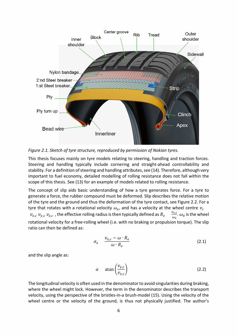
2. Tyre modelling fundamentals To analyse a vehicle’s motion and understand the performance limits of that motion, the tyres must be understood and mathematically modelled. Tyre properties affect the comfort, handling, traction, braking, steering, fuel economy, durability of suspension components and aerodynamics. The construction of a tyre is complex (see Figure 2.1), with many subcomponents and layers. Tyre subcomponents contain various rubber compounds and other materials that make analysis of the complete tyre challenging.
The tread is the part of the tyre that is in contact with the road. On a road vehicle, the tread should generate the greatest contact forces possible for traction, braking and steering. This is achieved by energy dissipation due to the hysteresis of the rubber compound (see (11) for example) and through adhesion between tyre and road (7), which may be jointly understood as friction. At the same time, the tyre should have low hysteresis at the frequencies for rolling resistance. In modern tyres, this is achieved by using silica as a filler material. This gives a rubber compound with low energy dissipation at rolling resistance frequencies and high energy dissipation at grip-related frequencies (7). Furthermore, the tread should minimise the influence of water on tyre-road interaction forces by allowing it to be temporarily stored within the groove (7).
Even though the tread is the actual contact with the road surface, the rest of the tyre carcass is important in maximising the effective contact area between tyre and road. Furthermore, the stiffness of the tyre carcass construction affects the transient response of the tyre. Lateral and torsional tyre deformation stiffnesses are both sensitive to tread stiffness. Lateral deformation stiffness is more sensitive to sidewall deformation stiffness, compared to torsional deformation stiffness. Torsional deformation stiffness shows a clear correlation with lateral slip stiffness, while the correlation between lateral deformation stiffness and lateral slip stiffness is weaker (12).
For vehicle dynamics purposes, understanding the tyre is crucial when modelling or analysing suspension systems, steering and braking systems. The tyre limits the maximum horizontal control force available to control the vehicle while cornering stiffness affects vehicle understeer behaviour and transient response in the linear tyre region, see Section 2.1. Furthermore, as discussed in Chapter 1, accurately modelling the tyre is essential when moving from real prototype development to virtual development.
There are many different tyre models for different purposes, from simple linear tyre models to ones based on Finite Element Methods (FEM). The model’s complexity and level of detail should be chosen based on its intended use. A linear model may be sufficient for modelling the vehicle motion at minor horizontal accelerations, whilst accurate modelling of rolling resistance may require a more complex model (depending on the intended use. See (13) for example).
6
Figure 2.1. Sketch of tyre structure, reproduced by permission of Nokian tyres.
This thesis focuses mainly on tyre models relating to steering, handling and traction forces. Steering and handling typically include cornering and straight-ahead controllability and stability. For a definition of steering and handling attributes, see (14). Therefore, although very important to fuel economy, detailed modelling of rolling resistance does not fall within the scope of this thesis. See (13) for an example of models related to rolling resistance.
The concept of slip aids basic understanding of how a tyre generates force. For a tyre to generate a force, the rubber compound must be deformed. Slip describes the relative motion of the tyre and the ground and thus the deformation of the tyre contact, see Figure 2.2. For a tyre that rotates with a rotational velocity 𝜔𝜔𝑥𝑥, and has a velocity at the wheel centre 𝑣𝑣𝑐𝑐 =[𝑣𝑣𝑥𝑥,𝑐𝑐 𝑣𝑣𝑦𝑦,𝑐𝑐 𝑣𝑣𝑧𝑧,𝑐𝑐], the effective rolling radius is then typically defined as 𝑅𝑅𝑟𝑟 = 𝑐𝑐𝑥𝑥,𝑐𝑐
𝜔𝜔0. 𝜔𝜔0 is the wheel
rotational velocity for a free-rolling wheel (i.e. with no braking or propulsion torque). The slip ratio can then be defined as:
𝜎𝜎𝑥𝑥 =𝑣𝑣𝑥𝑥,𝑐𝑐 − 𝜔𝜔 ∙ 𝑅𝑅𝑟𝑟
𝜔𝜔 ∙ 𝑅𝑅𝑟𝑟 (2.1)
and the slip angle as:
𝛼𝛼 = atan �𝑣𝑣𝑦𝑦,𝑐𝑐
𝑣𝑣𝑥𝑥,𝑐𝑐� (2.2)
The longitudinal velocity is often used in the denominator to avoid singularities during braking, where the wheel might lock. However, the term in the denominator describes the transport velocity, using the perspective of the bristles-in-a brush-model (15). Using the velocity of the wheel centre or the velocity of the ground, is thus not physically justified. The author’s

7
viewpoint is rather that the concept of slip ratio is not meaningful for a locked wheel. For a locked wheel, the sliding velocity is reasonably the most important variable and the total force is a result of the sliding friction between rubber and road. It could also be argued that the denominator in equation 2.2 should be changed to the angular velocity of the wheel times the effective radius.
The definition of the effective rolling radius is practical, as measuring the rotational velocity without any external torque is straightforward. However, due to the rolling resistance moment and corresponding longitudinal force in the contact patch, the tyre generates a small longitudinal force at the defined zero slip. Hence, a small deformation of the bristles would still occur and a small longitudinal force would be present at zero slip. An alternative definition of 𝑅𝑅𝑟𝑟 can be defined, where 𝜔𝜔𝑦𝑦,𝑐𝑐,0 is the rotational speed when 𝐹𝐹𝑥𝑥 = 0 as opposed to when the propulsion and braking torque are zero. However, this definition is more difficult to measure in practice and the previously mentioned definition is more commonly used.
Figure 2.2. Definition of wheel kinematic quantities.
When analysing tyre performance for steering, braking and traction, the force-slip curve is commonly used to describe tyre behaviour, see Figure 2.3. This reduction from describing the force based on two variables, the velocity of the wheel centre and the rotational velocity of the wheel, to a one-dimensional dependency related to the slip defined in Equation 2.1 is not obvious but supported by experiments and the brush model. The shape of this curve changes depending on the road surface and tyre properties. It also changes with operating conditions, due to the inherent simplifications made using slip (such as ignoring sliding velocity) and assumptions made in the mathematical tyre model. Two commonly defined model parameters are arguably the most important: slip stiffness and friction coefficient. Another important tyre model metric (that does not have to be explicitly expressed as a parameter) is the slip at which the force has maximum value. This value is important for slip control

8
functions, such as ABS (16). The maximum tyre-road friction coefficient in direction i is defined here as the maximum normalised horizontal force that the tyre can generate in that direction,
𝜇𝜇𝑖𝑖 ,𝑚𝑚𝑚𝑚𝑥𝑥 = max𝐹𝐹𝑖𝑖𝐹𝐹𝑧𝑧
(2.3)
The slip stiffness is defined as (9),
𝐶𝐶𝐹𝐹𝑖𝑖 =𝜕𝜕𝐹𝐹𝑖𝑖𝜕𝜕𝜎𝜎𝑖𝑖
|𝜎𝜎𝑖𝑖=0 (2.4)
where 𝑖𝑖 = 𝑥𝑥, 𝑦𝑦, 𝐹𝐹𝑖𝑖 is the tyre force in the contact patch, and 𝜎𝜎𝑖𝑖 is the slip. The above is a definition of the maximum tyre-road friction coefficient. It is a direct limitation of the maximum force that the tyre can generate in one direction and therefore also a limitation restricting possible vehicle motion. The tyre slip stiffness is also an important metric affecting complete vehicle behaviour, especially at low slip angles. Both these quantities change with operating conditions (17), road surface (10, 18), vertical load (9), tyre construction, wear (19, 20) and so on.
Figure 2.3. Typical shape of slip vs force curve. The drop after the peak is slightly exaggerated. Reproduced from (21).
Standardised tyre model interfaces for the input and output variables are required for efficient and accurate communication between tyre modelling and vehicle modelling software. The Standard Tyre Interface (STI), (22), is a commonly used interface for handling simulations. The interface has some disadvantages, one being how the road input to the tyre model is described by a single vertical height coordinate. The Cosin tyre interface (23) used in the Ftire model addresses the issue of road definition. However, the STI often provides good enough accuracy for handling smooth road simulations.
9
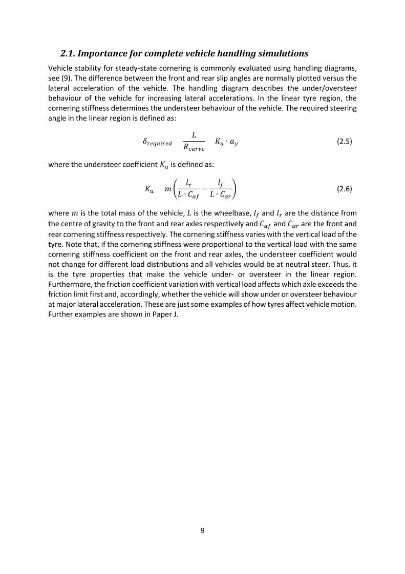
2.1. Importance for complete vehicle handling simulations Vehicle stability for steady-state cornering is commonly evaluated using handling diagrams, see (9). The difference between the front and rear slip angles are normally plotted versus the lateral acceleration of the vehicle. The handling diagram describes the under/oversteer behaviour of the vehicle for increasing lateral accelerations. In the linear tyre region, the cornering stiffness determines the understeer behaviour of the vehicle. The required steering angle in the linear region is defined as:
𝛿𝛿𝑟𝑟𝑟𝑟𝑟𝑟𝑢𝑢𝑖𝑖𝑟𝑟𝑟𝑟𝑑𝑑 =𝐿𝐿
𝑅𝑅𝑐𝑐𝑢𝑢𝑟𝑟𝑐𝑐𝑟𝑟+ 𝐾𝐾𝑢𝑢 ∙ 𝑎𝑎𝑦𝑦 (2.5)
where the understeer coefficient 𝐾𝐾𝑢𝑢 is defined as:
𝐾𝐾𝑢𝑢 = 𝑚𝑚�𝑙𝑙𝑟𝑟
𝐿𝐿 ∙ 𝐶𝐶𝛼𝛼𝑟𝑟−
𝑙𝑙𝑟𝑟𝐿𝐿 ∙ 𝐶𝐶𝛼𝛼𝑟𝑟
� (2.6)
where 𝑚𝑚 is the total mass of the vehicle, 𝐿𝐿 is the wheelbase, 𝑙𝑙𝑟𝑟 and 𝑙𝑙𝑟𝑟 are the distance from the centre of gravity to the front and rear axles respectively and 𝐶𝐶𝛼𝛼𝑟𝑟 and 𝐶𝐶𝛼𝛼𝑟𝑟 are the front and rear cornering stiffness respectively. The cornering stiffness varies with the vertical load of the tyre. Note that, if the cornering stiffness were proportional to the vertical load with the same cornering stiffness coefficient on the front and rear axles, the understeer coefficient would not change for different load distributions and all vehicles would be at neutral steer. Thus, it is the tyre properties that make the vehicle under- or oversteer in the linear region. Furthermore, the friction coefficient variation with vertical load affects which axle exceeds the friction limit first and, accordingly, whether the vehicle will show under or oversteer behaviour at major lateral acceleration. These are just some examples of how tyres affect vehicle motion. Further examples are shown in Paper J.

10
11
3. Online tyre model parameter identification Within the scope of this thesis, online tyre model parameter identification relates mostly to tyre-road friction coefficient estimation. In other words, estimating current vehicle performance limits. Since the maximum force that can be generated at the tyre-road interface varies for different road surfaces and road conditions, the tyre-road friction coefficient should be estimated as often as possible; ideally continuously and in front of the vehicle in its travel direction.
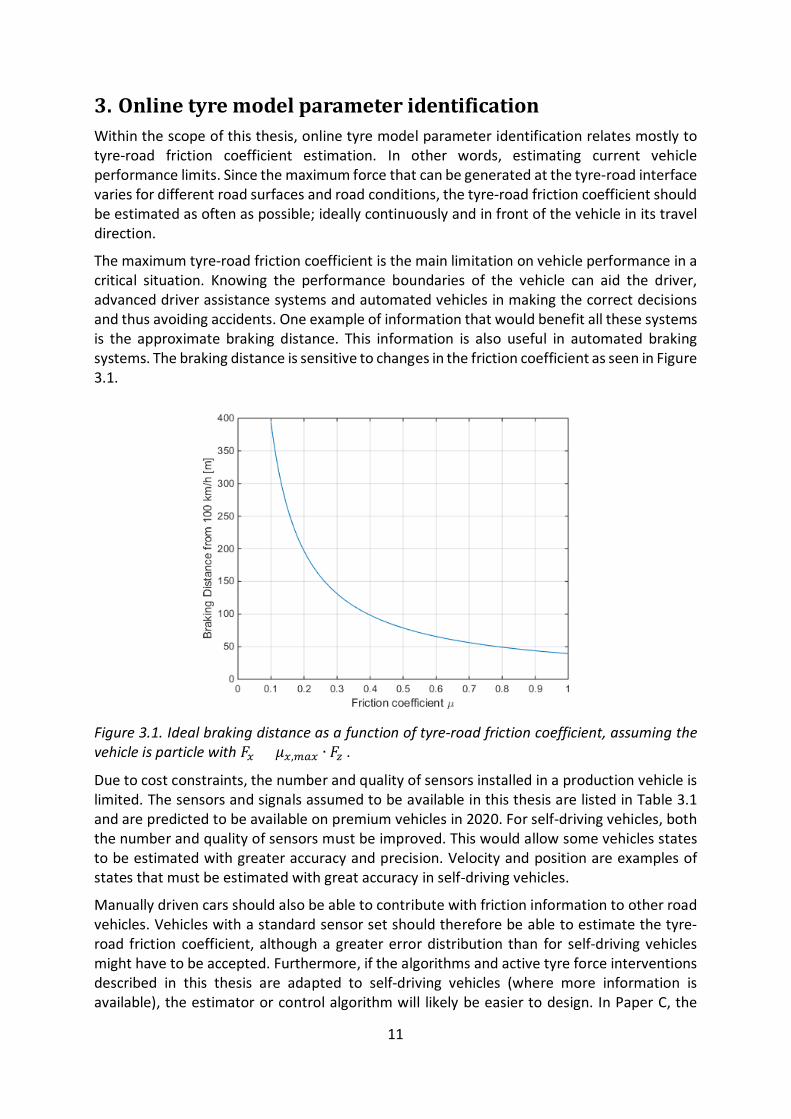
The maximum tyre-road friction coefficient is the main limitation on vehicle performance in a critical situation. Knowing the performance boundaries of the vehicle can aid the driver, advanced driver assistance systems and automated vehicles in making the correct decisions and thus avoiding accidents. One example of information that would benefit all these systems is the approximate braking distance. This information is also useful in automated braking systems. The braking distance is sensitive to changes in the friction coefficient as seen in Figure 3.1.
Figure 3.1. Ideal braking distance as a function of tyre-road friction coefficient, assuming the vehicle is particle with 𝐹𝐹𝑥𝑥 = 𝜇𝜇𝑥𝑥,𝑚𝑚𝑚𝑚𝑥𝑥 ∙ 𝐹𝐹𝑧𝑧 .
Due to cost constraints, the number and quality of sensors installed in a production vehicle is limited. The sensors and signals assumed to be available in this thesis are listed in Table 3.1 and are predicted to be available on premium vehicles in 2020. For self-driving vehicles, both the number and quality of sensors must be improved. This would allow some vehicles states to be estimated with greater accuracy and precision. Velocity and position are examples of states that must be estimated with great accuracy in self-driving vehicles.
Manually driven cars should also be able to contribute with friction information to other road vehicles. Vehicles with a standard sensor set should therefore be able to estimate the tyre-road friction coefficient, although a greater error distribution than for self-driving vehicles might have to be accepted. Furthermore, if the algorithms and active tyre force interventions described in this thesis are adapted to self-driving vehicles (where more information is available), the estimator or control algorithm will likely be easier to design. In Paper C, the

12
velocity of the vehicle is an example of a state that would make implementing the estimator and controller more straightforward, if known accurately.
Table 3.1. Signal sources used for online tyre model parameter identification, based on the table in (24).
Sensor/Signal Source Signals Notation
Inertial Measurement Unit
Longitudinal Acceleration 𝑎𝑎𝑥𝑥
Lateral Acceleration 𝑎𝑎𝑦𝑦
Vertical Acceleration 𝑎𝑎𝑧𝑧
Roll rate 𝜔𝜔𝑥𝑥
Pitch rate 𝜔𝜔𝑦𝑦
Yaw Rate 𝜔𝜔𝑧𝑧
Wheel speed sensors Wheel speed on each wheel 𝜔𝜔𝑤𝑤𝑖𝑖
Steering wheel angle sensor Steering wheel angle 𝛿𝛿𝑆𝑆𝑆𝑆𝑆𝑆
GPS (1Hz)
Position 𝑋𝑋,𝑌𝑌
Velocity 𝑉𝑉
Course Angle ϕz
Electric Motor Estimated Torque 𝑇𝑇𝐸𝐸𝐸𝐸
Motor Speed 𝜔𝜔𝐸𝐸𝐸𝐸
Internal Combustion Engine & Powertrain
Estimated Propulsion Torque
𝑇𝑇𝐼𝐼𝐼𝐼𝐸𝐸
Engine Speed 𝜔𝜔𝐼𝐼𝐼𝐼𝐸𝐸
Gear ratio 𝜂𝜂𝑒𝑒𝑟𝑟𝑚𝑚𝑟𝑟
3.1. Friction estimation strategies Different friction estimation strategies have been extensively investigated in previous research. The methods covered in this section are mainly limited to effect-based methods, as opposed to cause-based ones, see (25). Cause-based methods identify the environmental conditions that cause a low friction coefficient, such as low ambient temperature, snow, water on the road and so on. Effect-based approaches, on the other hand, identify the effect of low tyre-friction coefficient on the vehicle or tyre response. Effect-based approaches therefore have the advantage of estimating an actual tyre-road friction coefficient value.
13
Cause-based approaches have the advantage of being able to predict the friction coefficient ahead of the vehicle and can thus be used to warn the driver when approaching a sharp corner, or to decelerate if the vehicle has an automated driver. With cloud services, the main drawback of the effect-based approaches can be mitigated by collecting data from a large number of vehicles covering a major portion of the road network. This has been utilised in the Road Friction Information project (RFI) (26) and by the RoadCloud company (27). Naturally though, some precision in the tyre-road friction estimate is lost due to differences in tyres, load, temperature and so on between different vehicles.
Other effect-based approaches include accelerometers mounted in the inner liner of the tyre (28) which, while showing some promising results, have not yet been commercialised. Another common approach is to fit tyre models directly to the estimated or measured slip and force signals. Some elements of previous research have focused on estimating the slip slope (10, 18, 29) ( gradient of the force with respect to slip ratio at low utilisation levels) and then correlated this value to the tyre-road friction coefficient. Although it has been shown that different road surfaces have different slip stiffnesses (10, 18), no physical explanation or clear general correlation connecting tyre road-friction coefficient and slip stiffness has been demonstrated. If such a correlation were to be found, these methods would require low levels of tyre utilisation and thus provide an almost continuous estimate of the tyre-road friction coefficient.
Another common (and proven) method is to fit a nonlinear tyre model to the slip and force, or slip and aligning moment signals, see (15, 25, 30, 31) for example. These methods are described in the next section with the focus on estimating the longitudinal friction coefficient from the slip ratio and longitudinal force estimates. The main drawback of these methods is the requirement for large tyre force excitation. This means the tyres must operate close to the tyre-road friction limit, as shown in several of the papers appended to this thesis: Papers C, D, E, F and G.
3.2. Vehicle state and parameter estimation Relatively simple tyre models are often used for online tyre model parameter identification. Due to the lack of prior information about the tyres fitted to the vehicle, the inputs and outputs of the tyre model are estimated in real-time and the parameters of the tyre model are fitted to the measured data. The required input and output signals depend on the vehicle manoeuvre and tyre model but typically include tyre slip, horizontal force and vertical force of the tyre (32, 33). It should be possible to estimate these quantities based on available signals from the sensors in the production vehicle. Alternatively, load-sensing bearings can be used to estimate tyre forces, see (34) for example. Furthermore, some vehicle parameters, such as inertial parameters, must be estimated if there is to be an accurate force estimate. See (35-37) for different approaches to estimating inertial parameters and (38, 39) for methods of estimating the mass of the vehicle. The methods proposed within the scope of this thesis can be found in Paper B. Figure 3.2 shows a flow chart for an online tyre model parameter identification procedure and indicates the corresponding papers.

14
Figure 3.2. Flow chart of an approach to estimating the friction coefficient from available sensor signals. Reproduced from (24).
3.3. Tyre models for online identification of tyre model parameters For online identification of tyre model parameters within the scope of this thesis, the sensor set is limited to those found in vehicles on public roads, defined by the sensors in table 3.1. The small profit margins for passenger cars means that the cost of sensors used is normally limited. Consequently, the quality of sensor signals available for online tyre model parameter identification is also normally limited. Ideally, a friction estimate should be continuously available in the vehicle and the road surface may change. Thus, the time available for estimating the tyre-road friction coefficient is short. These limitations restrict the complexity of tyre models used in online tyre model parameter identification.
To identify the parameters of more complex tyre models, such as those for offline vehicle handling simulations, all relevant operating conditions that are modelled should be covered in the measurements used for fitting. For complex models, this is not feasible during normal driving. The main parameter of interest in online tyre model parameter identification is the tyre-road friction coefficient. This is because the maximum friction will limit the performance of the vehicle and thus affect braking distance and maximum cornering velocity, as discussed previously. However, to obtain an accurate friction coefficient estimate, the other tyre model parameters should be estimated alongside the tyre-road friction coefficient, as these may change from one road surface to another.
A simple, commonly-used tyre model is the brush model. This is a physical model describing the force and moment generation of the tyre due to tyre slippage. As its name suggests, the brush model divides the contact patch into infinitesimal bristles; deformation is then calculated for each bristle. The complexity of brush-type tyre models varies depending on the intended applications. Some implementations model individual bristles laterally and longitudinally (13). However, for online tyre parameter estimation, simpler versions are normally used with just a few parameters (see (15), for example). Furthermore, in the simpler models, assumptions must be made regarding the vertical pressure distribution in the contact patch. Two common assumptions are the parabolic pressure distribution and a constant pressure distribution. These give different shapes for the slip-force curve. Furthermore,
Inertial Parameter Estimation
Tyre Parameter Estimation
𝐹𝐹𝑥𝑥𝑖𝑖 ,𝐹𝐹𝑦𝑦𝑖𝑖 ,𝐹𝐹𝑧𝑧𝑖𝑖
𝜎𝜎𝑥𝑥𝑖𝑖
Tyre force Estimation
Slip Estimation
Sensor Signals
𝑚𝑚, 𝐼𝐼𝑧𝑧 , 𝑙𝑙𝑟𝑟𝜔𝜔𝑧𝑧,𝜔𝜔𝑤𝑤𝑖𝑖 ,𝑎𝑎𝑦𝑦 ,𝑎𝑎𝑥𝑥
𝛿𝛿𝑆𝑆𝑆𝑆𝑆𝑆,𝑇𝑇𝐸𝐸𝐸𝐸,𝑇𝑇𝐼𝐼𝐼𝐼𝐸𝐸
𝐶𝐶𝑥𝑥𝑖𝑖 ,𝜇𝜇𝑥𝑥𝑖𝑖
Paper B
Paper APaper C
(𝛼𝛼𝑖𝑖)
(𝐶𝐶𝑦𝑦𝑖𝑖 , 𝜇𝜇𝑦𝑦𝑖𝑖)

15
assumptions regarding the static and dynamic friction coefficient between tyre and road will also affect the shape of the curve. If these parameters have the same value, the force will have no peak and will converge to the limit imposed by the friction coefficient for large slip values. If the dynamic friction coefficient is set lower than the static friction coefficient, the slip-force curve will show a clear peak.
The simpler brush-based tyre models assume a constant bristle velocity throughout the contact patch. When the bristle enters the contact patch, it deforms until the deformation force exceeds the maximum force that the bristle can generate. The maximum horizontal force is limited by the vertical pressure and available friction between tyre and road. When the force from the bristle deformation exceeds the maximum friction force in the contact patch, the bristle starts sliding and generates a force proportional to the tyre-road friction coefficient. An assumption is made about the vertical pressure distribution along the length of the contact patch. Other tyre models for online tyre model parameter identification include: TM-Easy (40), Burckhardt model (41) and simpler versions of the magic formula (9). The choice of tyre model depends on the assumptions made by the developer of the estimator and the intended application. This thesis has investigated the suitability of selected tyre models for tyre-road friction estimation. This is further discussed in Section 3.4.4.
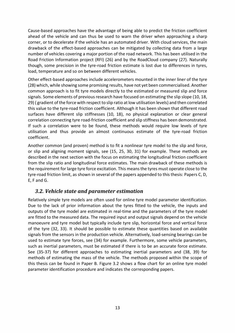
3.4. Active tyre force excitation Active tyre force excitation is a straightforward idea. A large tyre force is applied to one or more tyres for the purpose of estimating tyre-road friction. Figure 3.3 illustrates the basic problem of tyre-model-based tyre-road friction estimation methods, the need for high levels of tyre force excitation that justifies active tyre force excitation. Notice the similarity between the nonlinear and linear models when the tyre is operating at low-level forces. This makes it difficult to estimate the friction coefficient when the tyres are operating far from the maximum longitudinal force. Small tire forces are normal in everyday driving. Consequently, it is difficult to accurately estimate the peak of the nonlinear force-slip curve from data collected in normal driving.
With active tyre force excitation, the normalised tyre force is increased, while the driver’s intended path and speed are maintained. If the achieved normalised tyre force is large enough, the tyre-road friction coefficient can be determined from the data collected during the intervention. Even though this thesis focuses mainly on longitudinal excitation in straight-ahead driving, similar strategies can be implemented for cornering. Active tyre force excitation has been previously investigated in (42, 43) and some implementations have also been patented. See (44, 45) for previous patents and (46, 47) for patents based on a research project connected to the work in this thesis.
16
Figure 3.3. Illustration of need for active tyre force excitation. Notice how similar the linear model is to the non-linear model, for small normalised tyre forces far from the friction limit.
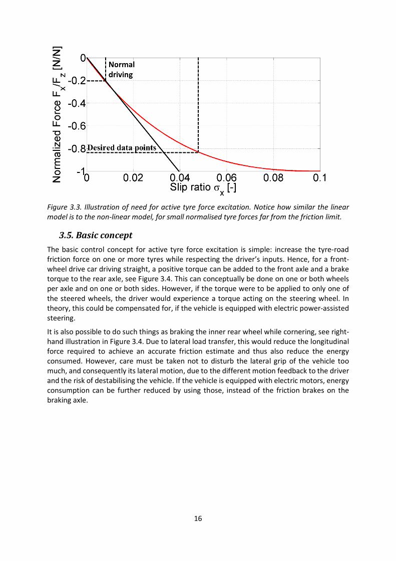
3.5. Basic concept The basic control concept for active tyre force excitation is simple: increase the tyre-road friction force on one or more tyres while respecting the driver’s inputs. Hence, for a front-wheel drive car driving straight, a positive torque can be added to the front axle and a brake torque to the rear axle, see Figure 3.4. This can conceptually be done on one or both wheels per axle and on one or both sides. However, if the torque were to be applied to only one of the steered wheels, the driver would experience a torque acting on the steering wheel. In theory, this could be compensated for, if the vehicle is equipped with electric power-assisted steering.
It is also possible to do such things as braking the inner rear wheel while cornering, see right-hand illustration in Figure 3.4. Due to lateral load transfer, this would reduce the longitudinal force required to achieve an accurate friction estimate and thus also reduce the energy consumed. However, care must be taken not to disturb the lateral grip of the vehicle too much, and consequently its lateral motion, due to the different motion feedback to the driver and the risk of destabilising the vehicle. If the vehicle is equipped with electric motors, energy consumption can be further reduced by using those, instead of the friction brakes on the braking axle.

17
Figure 3.4. Some basic concepts for force application in active tyre force excitation. Left: basic excitation strategy when driving straight ahead.
3.6. Limitations The work within this thesis has covered some of the basic questions related to the excitation and estimation strategy for active tyre force excitation, but many other factors not included here should be considered for production implementations of similar systems.
One of the main limitations of the first implementation in Paper C was that it did not take into account vehicle stability. A maximum torque was set and the engine management system attempted to reach that torque without any feedback. Hence, the vehicle became unstable, its rear wheels locking when the maximum torque was set higher than the tyre-road friction limit would allow. The vehicle motion and stability during these manoeuvres was investigated in a Master’s thesis as part of the research project, see (48). However, further studies on vehicle stability during this manoeuvre are required. An active tyre force excitation system which considers vehicle stability should also be evaluated. Section 3.4.5 provides a few suggestions on excitation strategies, but these need further investigation to ensure vehicle stability during this type of intervention.
Another crucial aspect from is acceptance from the end customer of the vehicle, mainly in relation to comfort, tyre wear and energy efficiency. Two different viewpoints can be taken regarding comfort: either driver disturbance should be minimised during the intervention, or the driver should be able to notice a difference in the vehicle when the intervention is carried out. Both these strategies could be used, depending on whether the intervention is initiated by the driver or a real-time system requiring friction information.
Reducing driver discomfort would likely increase the intervention time since slower force gradients would probably have to be used. This would also increase the energy consumed during the intervention. The energy aspect has not been considered in this thesis, other than a brief discussion in Section 3.4.6, where a simple calculation is used to derive the additional fuel consumption for some interventions. If implemented in a production vehicle, the additional energy consumption should be reduced as much as possible. Implementing these types of systems would add opposing safety and energy consumption requirements, on an overall vehicular level.
Actuator limitations have not been studied extensively within this thesis. The main actuator limitation considered was the limited torque gradient of the internal combustion engine in Paper C. Naturally, actuation of the friction brakes also has limitations in terms of delays and bandwidth. In the tests, the limited actuator performance implicitly affects the results.

18
However, for the implementation in simulation software in this thesis (mainly IPG Carmaker (49)) no actuator limitations are considered.
3.7. Tyre models for active tyre force excitation The suitability of different tyre models for tyre-road friction estimation using active tyre force excitation was investigated in Papers D, E, G and to some extent in Paper F. Paper F shows that for a simple tyre model in a noise free environment with only two parameters, the main factor affecting the required utilisation (as a ratio of the maximum force) is neither the slip stiffness nor the friction coefficient but the shape of the slip-force curve. Hence, if the shape of the force-slip curve were to remain the same or similar between different road surfaces, the same tyre model could be used for all road surfaces. However, as shown in Paper D, E and G the tyre characteristics change substantially between different road surfaces and different simple tyre models will fit different surfaces with varying accuracy.
The simple brush model, with two parameters and parabolic vertical pressure distribution, fits measurements on asphalt well but not on snow. The Dugoff model (50), which is also based on the brush model theory but with a constant vertical pressure distribution, had a reasonable fit on both snow and wet asphalt and, more importantly, gave low friction estimation errors for both road surfaces. The Magic formula (51) performed quite well on these two road surfaces, both when the shape factor was set to 1 or estimated. Hence, based on the tyre models investigated and the articles appended to this thesis, the Dugoff model or 3-4 parameter Magic Formula tyre model are recommended. The differences in performance between different tyre models was studied extensively in some of the papers appended in this thesis, see Papers D, E, F and G.
3.8. Different strategies for torque application With active tyre force excitation, the excitation can be controlled to provide data that increases the performance of the tyre-road friction estimator. Hence, a new degree of freedom is added to the estimation problem. Instead of designing an estimator that performs well for the type of data that could be expected from a human driver, the excitation and estimator can be developed simultaneously. Different excitation strategies have been investigated in previous work by the author.
Paper E investigated suitable excitation strategies when using a few different tyre models in the estimator. Naturally, the optimal excitation depends on both the chosen tyre model and current road surface. This is mainly due to modelling errors for a given tyre model on the current road surface. Excitations that have been optimised for a certain tyre model and road surface cannot therefore be achieved in practice, but serve as a benchmark for other excitation strategies. Of the excitation strategies investigated in the work within this thesis, a simple force ramp proved to be the most successful. Except providing satisfactory performance for the tested tyre models and surfaces, it is also straightforward to implement.
3.9. Implemented excitation strategies Two different excitation strategies have been implemented: one straightforward method using a PID-controller and torque ramp and one more advanced implementation using a extremum-seeking algorithm. The first approach has been tested in a real vehicle. However, this method is not feasible to put into production. The extremum-seeking algorithm is close

19
to a production method. However, it needs to be further validated in a real vehicle and in terms of vehicle stability.
3.9.1. PID controller A straightforward excitation strategy was used for the proof-of-concept in Paper C. See Figure 3.5 for a conceptual implementation excitation strategy. A ramp was used as the requested engine torque to the engine management unit and the brake torque was controlled by a PID controller, to keep the set velocity of the vehicle constant. The vehicle is front-wheel drive, so the brake torque request was sent to the rear brakes. This implementation is only intended for use in feasibility studies for active tyre force excitation and to investigate how the tyre-road friction coefficient can be estimated from the on-board sensors.
Figure 3.5. Control strategy implemented in Paper C.
This simple implementation does not take vehicle stability into consideration and will lock the rear wheels if the requested engine torque is too great. A straightforward solution to the problem of locking the rear wheels is to limit the maximum allowed slip. This can be achieved by such means as measuring or estimating the longitudinal slip ratio and simply reducing the requested torques when the slip ratio is too great. However, this introduces a few new challenges, one of which was experienced during the experiments in Paper C.
During the measurements, the maximum allowed slip ratio for the wheels on the test vehicle was limited by a lower level brake pressure controller. The rear wheels would not therefore reach lock-up on the high-friction surfaces, even under high lateral accelerations. On the low-friction surface however (in this case wet basalt), the rear wheels locked up consistently even in straight-ahead driving. This was likely due to the difference in slip ratio at the maximum tyre force between the different surfaces. The main challenge with setting slip ratio limits is clearly illustrated by these experiments. In other words, the limit should be changed depending on the road surface and tyre. Hence, the tyre-road characteristics should be known in order to set the controller limitations. However, the purpose of the intervention is to estimate the tyre-road characteristics. Another strategy is therefore needed which does not require any a priori information about the road surface or tyres fitted to the vehicle.
3.9.2. Extremum-seeking algorithms Extremum-seeking algorithms present a possible solution to the problem of the requirement for a priori information. Extremum-seeking algorithms have previously been implemented for
Set DesiredVelocity
𝑣𝑣𝑥𝑥,𝑟𝑟𝑟𝑟𝑟𝑟
+- 𝑒𝑒𝑐𝑐𝑥𝑥
PID Controller𝑇𝑇𝑏𝑏𝑟𝑟𝑚𝑚𝑏𝑏𝑟𝑟,𝑟𝑟𝑟𝑟𝑚𝑚𝑟𝑟
TorqueRamp
𝑧−1
𝑇𝑇𝑟𝑟𝑖𝑖𝑒𝑒𝑖𝑖𝑖𝑖𝑟𝑟,𝑟𝑟𝑟𝑟𝑓𝑓𝑖𝑖𝑖𝑖
𝑎𝑎𝑐𝑡𝑡𝑖𝑖𝑣𝑣𝑎𝑎𝑡𝑡𝑖𝑖𝑜𝑛 𝑠𝑠𝑖𝑖𝑔𝑛𝑎𝑎𝑙𝑙
𝑣𝑣𝑥𝑥
20
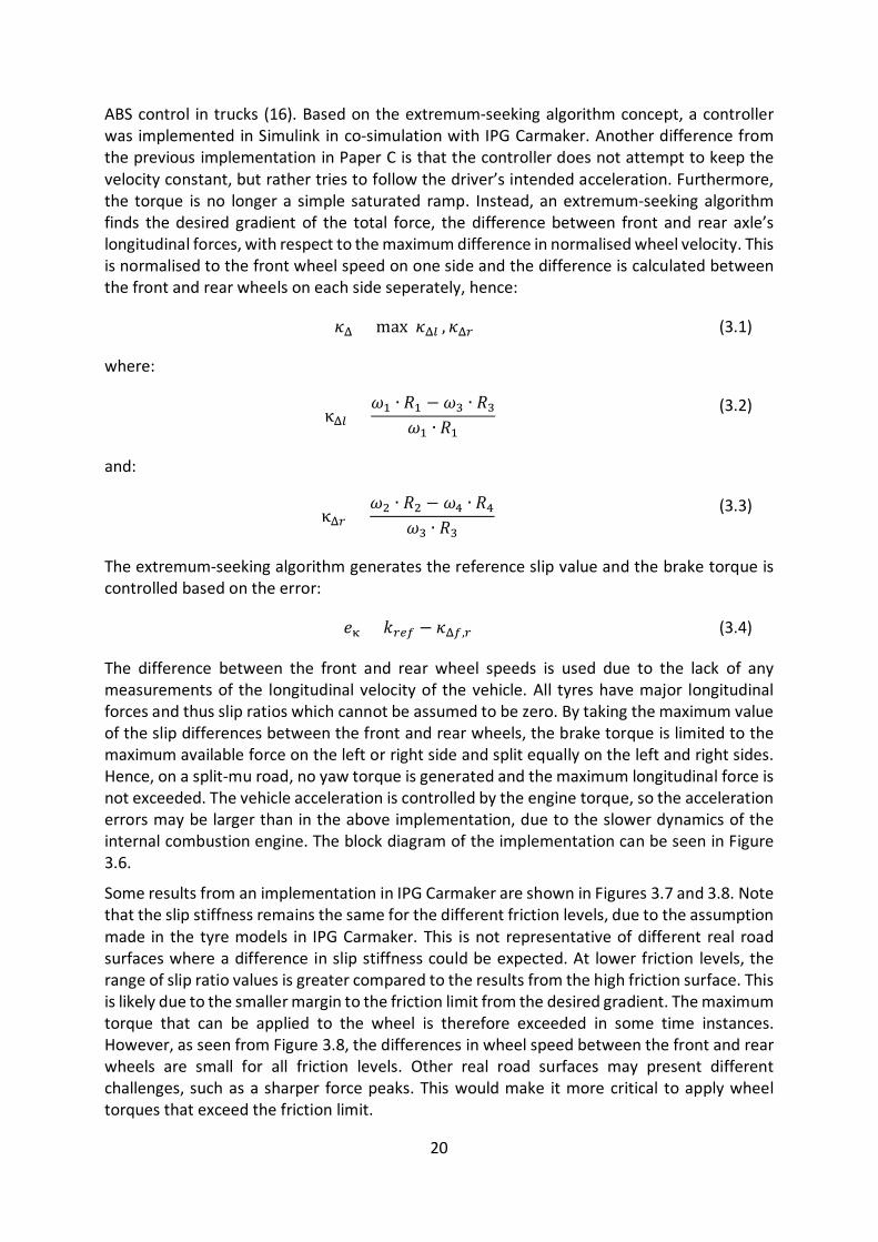
ABS control in trucks (16). Based on the extremum-seeking algorithm concept, a controller was implemented in Simulink in co-simulation with IPG Carmaker. Another difference from the previous implementation in Paper C is that the controller does not attempt to keep the velocity constant, but rather tries to follow the driver’s intended acceleration. Furthermore, the torque is no longer a simple saturated ramp. Instead, an extremum-seeking algorithm finds the desired gradient of the total force, the difference between front and rear axle’s longitudinal forces, with respect to the maximum difference in normalised wheel velocity. This is normalised to the front wheel speed on one side and the difference is calculated between the front and rear wheels on each side seperately, hence:
𝜅𝜅Δ = max(𝜅𝜅Δ𝑙𝑙 , 𝜅𝜅Δ𝑟𝑟) (3.1)
where:
κΔ𝑙𝑙 =𝜔𝜔1 ∙ 𝑅𝑅1 − 𝜔𝜔3 ∙ 𝑅𝑅3
𝜔𝜔1 ∙ 𝑅𝑅1 (3.2)
and:
κΔ𝑟𝑟 =𝜔𝜔2 ∙ 𝑅𝑅2 − 𝜔𝜔4 ∙ 𝑅𝑅4
𝜔𝜔3 ∙ 𝑅𝑅3 (3.3)
The extremum-seeking algorithm generates the reference slip value and the brake torque is controlled based on the error:
𝑒𝑒κ = 𝑘𝑘𝑟𝑟𝑟𝑟𝑟𝑟 − 𝜅𝜅Δ𝑟𝑟,𝑟𝑟 (3.4)
The difference between the front and rear wheel speeds is used due to the lack of any measurements of the longitudinal velocity of the vehicle. All tyres have major longitudinal forces and thus slip ratios which cannot be assumed to be zero. By taking the maximum value of the slip differences between the front and rear wheels, the brake torque is limited to the maximum available force on the left or right side and split equally on the left and right sides. Hence, on a split-mu road, no yaw torque is generated and the maximum longitudinal force is not exceeded. The vehicle acceleration is controlled by the engine torque, so the acceleration errors may be larger than in the above implementation, due to the slower dynamics of the internal combustion engine. The block diagram of the implementation can be seen in Figure 3.6.
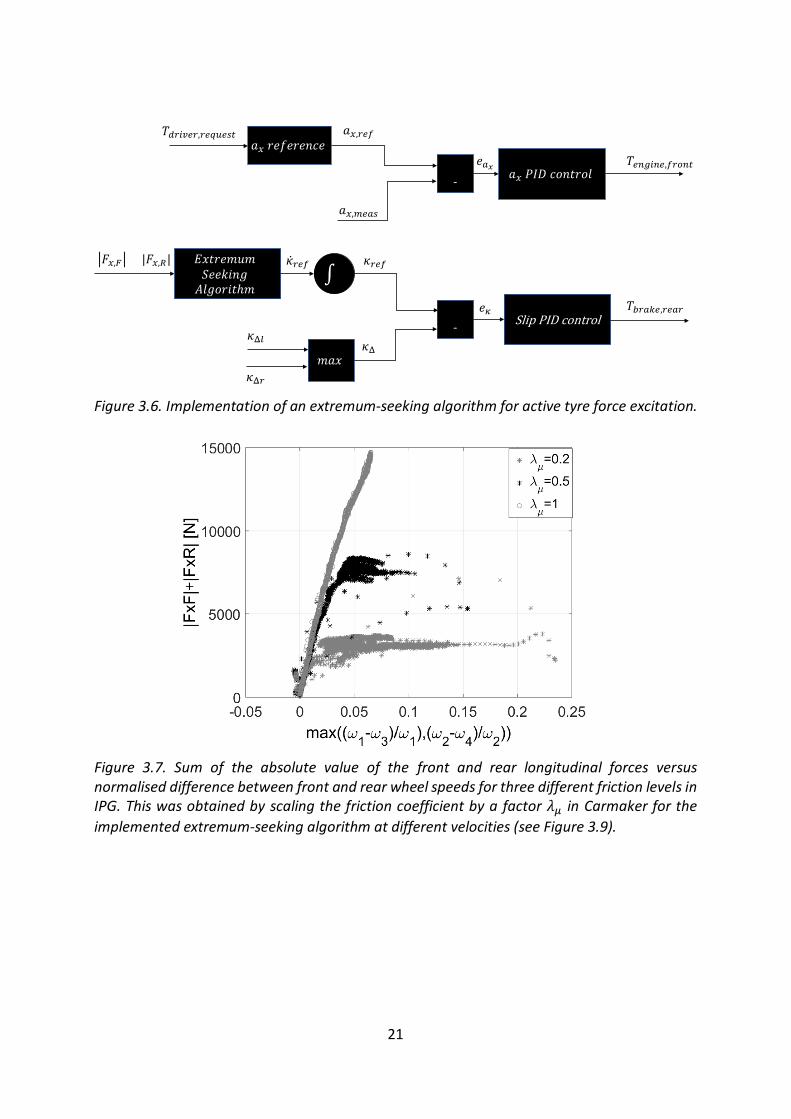
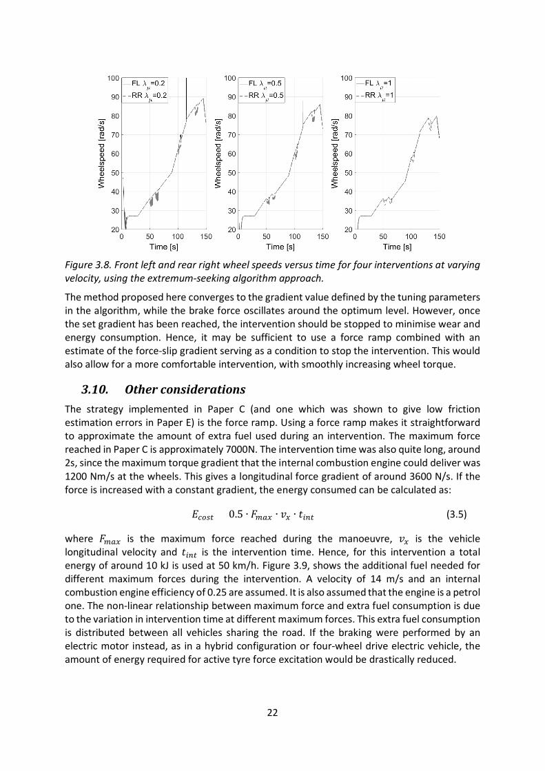
Some results from an implementation in IPG Carmaker are shown in Figures 3.7 and 3.8. Note that the slip stiffness remains the same for the different friction levels, due to the assumption made in the tyre models in IPG Carmaker. This is not representative of different real road surfaces where a difference in slip stiffness could be expected. At lower friction levels, the range of slip ratio values is greater compared to the results from the high friction surface. This is likely due to the smaller margin to the friction limit from the desired gradient. The maximum torque that can be applied to the wheel is therefore exceeded in some time instances. However, as seen from Figure 3.8, the differences in wheel speed between the front and rear wheels are small for all friction levels. Other real road surfaces may present different challenges, such as a sharper force peaks. This would make it more critical to apply wheel torques that exceed the friction limit.
21
Figure 3.6. Implementation of an extremum-seeking algorithm for active tyre force excitation.
Figure 3.7. Sum of the absolute value of the front and rear longitudinal forces versus normalised difference between front and rear wheel speeds for three different friction levels in IPG. This was obtained by scaling the friction coefficient by a factor 𝜆𝜆𝜇𝜇 in Carmaker for the implemented extremum-seeking algorithm at different velocities (see Figure 3.9).
𝑎𝑎𝑥𝑥 𝑟𝑟𝑒𝑒𝑓𝑒𝑒𝑟𝑟𝑒𝑒𝑛𝑐𝑒𝑒+-
𝑎𝑎𝑥𝑥,𝑚𝑚𝑟𝑟𝑚𝑚𝑟𝑟
𝑎𝑎𝑥𝑥,𝑟𝑟𝑟𝑟𝑟𝑟
𝑎𝑎𝑥𝑥 𝑃𝐼𝐼𝐷 𝑐𝑜𝑛𝑡𝑡𝑟𝑟𝑜𝑙𝑙𝑒𝑒𝑚𝑚𝑥𝑥 𝑇𝑇𝑟𝑟𝑖𝑖𝑒𝑒𝑖𝑖𝑖𝑖𝑟𝑟,𝑟𝑟𝑟𝑟𝑓𝑓𝑖𝑖𝑖𝑖
𝐸𝐸𝑥𝑥𝑡𝑡𝑟𝑟𝑒𝑒𝑚𝑚𝑢𝑚𝑚 𝑆𝑒𝑒𝑒𝑒𝑘𝑘𝑖𝑖𝑛𝑔 𝐴𝑙𝑙𝑔𝑜𝑟𝑟𝑖𝑖𝑡𝑡ℎ𝑚𝑚
𝐹𝐹𝑥𝑥,𝐹𝐹 + |𝐹𝐹𝑥𝑥,𝑅𝑅|∫
�̇�𝜅𝑟𝑟𝑟𝑟𝑟𝑟 𝜅𝜅𝑟𝑟𝑟𝑟𝑟𝑟
𝜅𝜅Δ𝑙𝑙
𝜅𝜅Δ𝑟𝑟𝑚𝑚𝑎𝑎𝑥𝑥
+- Slip PID control
𝑇𝑇𝑏𝑏𝑟𝑟𝑚𝑚𝑏𝑏𝑟𝑟,𝑟𝑟𝑟𝑟𝑚𝑚𝑟𝑟
𝜅𝜅Δ
𝑒𝑒𝜅
𝑇𝑇𝑑𝑑𝑟𝑟𝑖𝑖𝑐𝑐𝑟𝑟𝑟𝑟,𝑟𝑟𝑟𝑟𝑟𝑟𝑢𝑢𝑟𝑟𝑟𝑟𝑖𝑖
22
Figure 3.8. Front left and rear right wheel speeds versus time for four interventions at varying velocity, using the extremum-seeking algorithm approach.
The method proposed here converges to the gradient value defined by the tuning parameters in the algorithm, while the brake force oscillates around the optimum level. However, once the set gradient has been reached, the intervention should be stopped to minimise wear and energy consumption. Hence, it may be sufficient to use a force ramp combined with an estimate of the force-slip gradient serving as a condition to stop the intervention. This would also allow for a more comfortable intervention, with smoothly increasing wheel torque.
3.10. Other considerations The strategy implemented in Paper C (and one which was shown to give low friction estimation errors in Paper E) is the force ramp. Using a force ramp makes it straightforward to approximate the amount of extra fuel used during an intervention. The maximum force reached in Paper C is approximately 7000N. The intervention time was also quite long, around 2s, since the maximum torque gradient that the internal combustion engine could deliver was 1200 Nm/s at the wheels. This gives a longitudinal force gradient of around 3600 N/s. If the force is increased with a constant gradient, the energy consumed can be calculated as:
𝐸𝐸𝑐𝑐𝑓𝑓𝑟𝑟𝑖𝑖 = 0.5 ∙ 𝐹𝐹𝑚𝑚𝑚𝑚𝑥𝑥 ∙ 𝑣𝑣𝑥𝑥 ∙ 𝑡𝑡𝑖𝑖𝑖𝑖𝑖𝑖 (3.5)
where 𝐹𝐹𝑚𝑚𝑚𝑚𝑥𝑥 is the maximum force reached during the manoeuvre, 𝑣𝑣𝑥𝑥 is the vehicle longitudinal velocity and 𝑡𝑡𝑖𝑖𝑖𝑖𝑖𝑖 is the intervention time. Hence, for this intervention a total energy of around 10 kJ is used at 50 km/h. Figure 3.9, shows the additional fuel needed for different maximum forces during the intervention. A velocity of 14 m/s and an internal combustion engine efficiency of 0.25 are assumed. It is also assumed that the engine is a petrol one. The non-linear relationship between maximum force and extra fuel consumption is due to the variation in intervention time at different maximum forces. This extra fuel consumption is distributed between all vehicles sharing the road. If the braking were performed by an electric motor instead, as in a hybrid configuration or four-wheel drive electric vehicle, the amount of energy required for active tyre force excitation would be drastically reduced.

23
Figure 3.9. Energy consumption versus maximum axle force during the intervention, for an intervention interval of 200m. Note that the energy consumption should be split between several vehicles on the road.
The comfort aspect has not been investigated in this study. Comfort is of course a very important aspect. It is the author’s opinion that the intervention should not be concealed from the driver of the vehicle. If the driver is aware that an intervention is ongoing, he/she is probably more likely to accept minor disturbances in vehicle motion. Furthermore, the increased tyre wear due to active tyre force excitation interventions has not been investigated. A principal study should be done to avoid excessive tyre wear, which could result in greater tyre particle emissions and worse customer acceptance. During the experiments in Paper C, some observations could be made regarding comfort during active tyre force excitation. While the ride quality was not subjectively affected (at least for the smooth roads that the system was tested on), louder engine noise was noticed during the intervention, as well as some sound from the friction brakes. This noise would be difficult to conceal from the driver in a quiet environment. However, further studies are required to evaluate the concept systematically.

24

25
4. Offline tyre model parameter identification Complete vehicle simulation models offer a way to make the development process for both active safety systems and autonomous vehicles more efficient. However, this is only valid under the assumption that the complete vehicle model represents the conditions to be investigated. Hence, the complete vehicle model and all sub-models must have adequate accuracy for the model to be useful. The tyres are some of the main components affecting the vehicle motion. Thus, the ability to model tyres accurately is essential when validating the complete vehicle model against measurement data.
For complete vehicle motion simulations, the tyre models used are often more complex compared to the ones used for online tyre-road friction estimation. This is mainly due to the requirement for an accurate description of the force and moments generated in the tyre contact patch and the possibility of using a more time-consuming tyre model parameter identification procedure. An accurate tyre model is also required to validate full vehicle simulation models on a system level; comparing full-vehicle measurements with simulations, for example. For offline tyre model parameter identification, the operating conditions of the tyre can be controlled freely within the limitations of the tyre testing equipment.
Naturally, all mathematical tyre models used to simulate the force and moment generation of the tyres require a parameter identification procedure. The number of measurements required to identify the parameters of a tyre model depends on the complexity of the model as well as the modelling principle. In general, physical tyre models require fewer measurements for parametrisation than empirical tyre models. As for any system identification procedure, the data used for parameter identification should cover enough operating points so that the model is valid in its intended range of use.
From a vehicle motion perspective, the intended range of use can be described by the manoeuvres which will be performed and the resulting operating conditions of the tyre. Hence, the tyre model should perform well for certain conditions. If the data does not cover the relevant operating conditions, there is a risk that the model will be overfitted to measurements points that do not fully describe the range of operation. It can thus behave unexpectedly when used outside the measurement range. It should be remembered that any data can be fitted with enough parameters, but this does not imply validity beyond the data range used for parameter identification.
To find the tyre model parameters, a cost function is normally formulated and minimised, typically minimising the difference between the outputs of the tyre model and corresponding measured signals. Optimisation algorithms are used to minimise the formulated cost functions. Classical optimisation algorithms mainly developed within mathematics are suitable for convex optimisation problems (52). The work in this thesis has used both stochastic and classical optimisation methods. Stochastic optimisation methods are particularly well-suited to finding an optimum, in optimisation problems that are not convex. Due to the stochasticity of these algorithms, different results may be found from running the same algorithm for the same optimisation problem. As pointed out in (52), this does not have to be a disadvantage since several equally viable solutions can be found.

26
4.1. Tyre models The tyre model itself and the assumptions made when deriving the model is important for how accurately the force and moment characteristics of the tyre can be represented by the model. Tyre models vary from simple models as those presented in Section 3.3, to more complex models presented in this section. Although complex tyre models normally can represent the force and moment characteristics more accurately than simple tyre models, they are also more computationally expensive and requires more resources for parameter identification. The tyre models should thus be chosen with the intended use in mind to avoid long identification procedures and long simulation time for small accuracy improvements.
4.2. Steady-state models Steady-state models are models which have no memory. Hence, the output variables are dependent only on the input variables at the current time instant, not on past and future input and output variables. In the tyre modelling perspective, it is thus assumed that the transient delays of changing shear stress and deformation (in both contact patch and tyre carcass) are not modelled.
One of the most frequently used tyre models for handling simulations is the empirical model referred to as the Magic Formula (MF) (51). This model is a de facto standard within the automotive industry. It has been updated a number of times over the years and one of its more commonly used versions is the Pacejka 2002 model (9). The number of parameters varies for different versions, but a full combined slip model has around 100. The basic structure of the model can be seen in (9). Even though the basic equations in the Pacejka 2002 model mean it steady-state, low-frequency tyre dynamics can be included by adding a tyre relaxation model to the slip definition.
4.3. Dynamic tyre models By definition, steady-state tyre models cannot model tyre temperature due to a lack of time history (dynamic states). A commercial tyre model used to model tyre temperature is Tametire. Tametire has a transient mechanical model valid up to around 10-20Hz with an additional thermal model affecting such things as slip stiffness and friction coefficient (53). The focus of Tametire is on handling and traction simulations. Unlike some other dynamic tyre models, it is not intended for use in comfort and durability simulations.
Although steady-state has traditionally been considered accurate enough for vehicle handling simulations on smooth roads, dynamic tyre models have been used quite extensively for other applications. For instance, MF-swift (54) and Ftire (55) are commonly used in comfort and durability simulations. However, previous work has also shown the importance of modelling tyre dynamics for handling and braking simulations on rough roads (56) and during ABS braking (57). As seen in Paper H, dynamic tyre models could improve accuracy in vehicle steady-state manoeuvres, when large lateral tire vibrations are present. Furthermore, the tyre surface temperature should be modelled to produce accurate results for a variety of vehicle manoeuvres, see Paper J.
MF-Swift is a rigid ring tyre model (54), see Figure 4.1. The tyre is modelled as a rigid ring connected to the rim with springs and dampers. It therefore captures the tyre forces dynamics when, say, the tyre travels over a rough road surface or when it is excited from ABS braking.
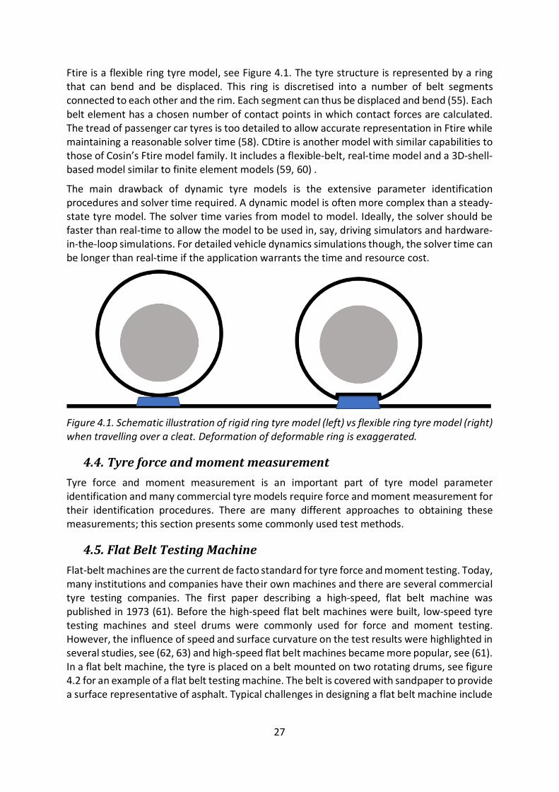
27
Ftire is a flexible ring tyre model, see Figure 4.1. The tyre structure is represented by a ring that can bend and be displaced. This ring is discretised into a number of belt segments connected to each other and the rim. Each segment can thus be displaced and bend (55). Each belt element has a chosen number of contact points in which contact forces are calculated. The tread of passenger car tyres is too detailed to allow accurate representation in Ftire while maintaining a reasonable solver time (58). CDtire is another model with similar capabilities to those of Cosin’s Ftire model family. It includes a flexible-belt, real-time model and a 3D-shell-based model similar to finite element models (59, 60) .
The main drawback of dynamic tyre models is the extensive parameter identification procedures and solver time required. A dynamic model is often more complex than a steady-state tyre model. The solver time varies from model to model. Ideally, the solver should be faster than real-time to allow the model to be used in, say, driving simulators and hardware-in-the-loop simulations. For detailed vehicle dynamics simulations though, the solver time can be longer than real-time if the application warrants the time and resource cost.
Figure 4.1. Schematic illustration of rigid ring tyre model (left) vs flexible ring tyre model (right) when travelling over a cleat. Deformation of deformable ring is exaggerated.
4.4. Tyre force and moment measurement Tyre force and moment measurement is an important part of tyre model parameter identification and many commercial tyre models require force and moment measurement for their identification procedures. There are many different approaches to obtaining these measurements; this section presents some commonly used test methods.
4.5. Flat Belt Testing Machine Flat-belt machines are the current de facto standard for tyre force and moment testing. Today, many institutions and companies have their own machines and there are several commercial tyre testing companies. The first paper describing a high-speed, flat belt machine was published in 1973 (61). Before the high-speed flat belt machines were built, low-speed tyre testing machines and steel drums were commonly used for force and moment testing. However, the influence of speed and surface curvature on the test results were highlighted in several studies, see (62, 63) and high-speed flat belt machines became more popular, see (61). In a flat belt machine, the tyre is placed on a belt mounted on two rotating drums, see figure 4.2 for an example of a flat belt testing machine. The belt is covered with sandpaper to provide a surface representative of asphalt. Typical challenges in designing a flat belt machine include
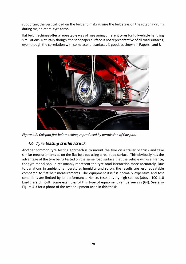
28
supporting the vertical load on the belt and making sure the belt stays on the rotating drums during major lateral tyre force.
flat belt machines offer a repeatable way of measuring different tyres for full-vehicle handling simulations. Naturally though, the sandpaper surface is not representative of all road surfaces, even though the correlation with some asphalt surfaces is good, as shown in Papers I and J.
Figure 4.2. Calspan flat belt machine, reproduced by permission of Calspan.
4.6. Tyre testing trailer/truck Another common tyre testing approach is to mount the tyre on a trailer or truck and take similar measurements as on the flat belt but using a real road surface. This obviously has the advantage of the tyre being tested on the same road surface that the vehicle will use. Hence, the tyre model should reasonably represent the tyre-road interaction more accurately. Due to variations in ambient temperature, humidity and so on, the results are less repeatable compared to flat belt measurements. The equipment itself is normally expensive and test conditions are limited by its performance. Hence, tests at very high speeds (above 100-110 km/h) are difficult. Some examples of this type of equipment can be seen in (64). See also Figure 4.3 for a photo of the test equipment used in this thesis.
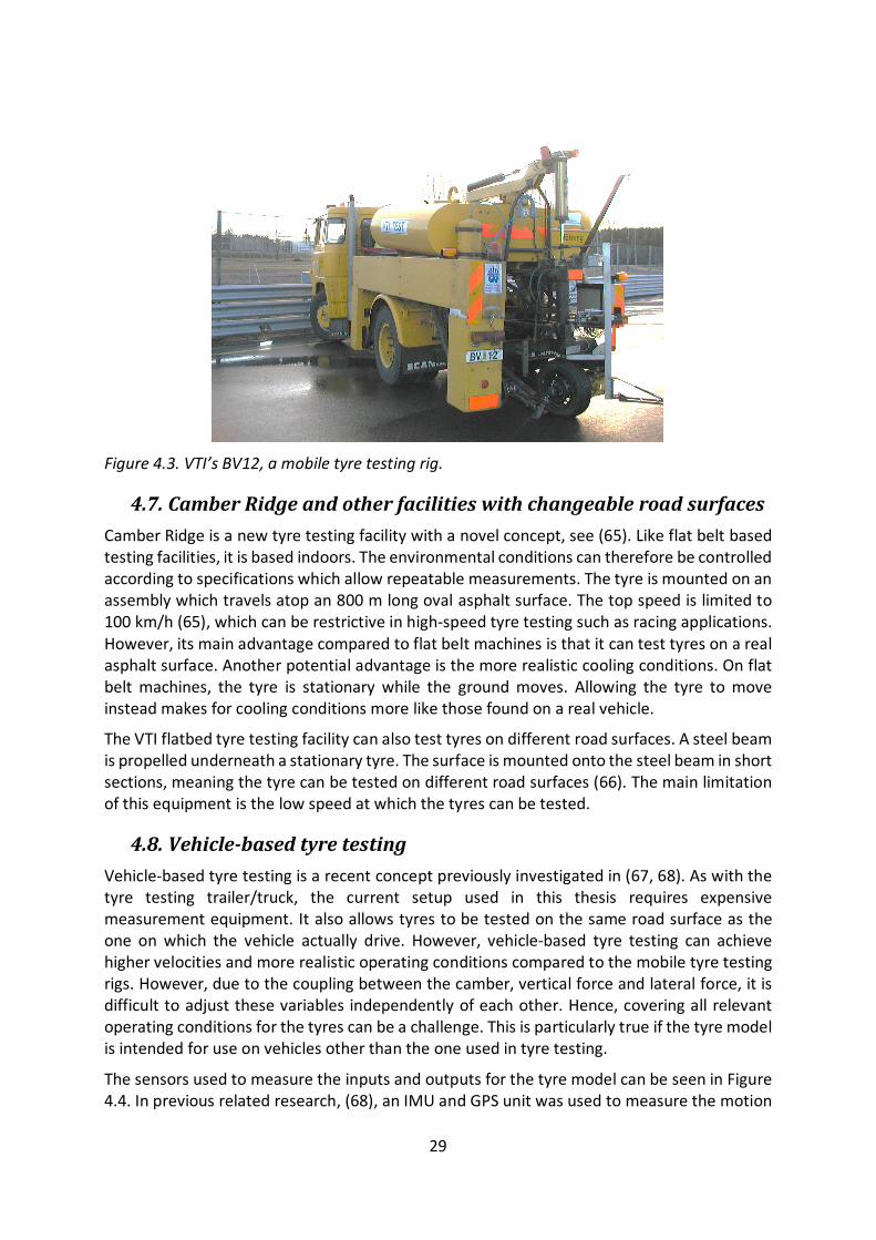
29
Figure 4.3. VTI’s BV12, a mobile tyre testing rig.
4.7. Camber Ridge and other facilities with changeable road surfaces Camber Ridge is a new tyre testing facility with a novel concept, see (65). Like flat belt based testing facilities, it is based indoors. The environmental conditions can therefore be controlled according to specifications which allow repeatable measurements. The tyre is mounted on an assembly which travels atop an 800 m long oval asphalt surface. The top speed is limited to 100 km/h (65), which can be restrictive in high-speed tyre testing such as racing applications. However, its main advantage compared to flat belt machines is that it can test tyres on a real asphalt surface. Another potential advantage is the more realistic cooling conditions. On flat belt machines, the tyre is stationary while the ground moves. Allowing the tyre to move instead makes for cooling conditions more like those found on a real vehicle.
The VTI flatbed tyre testing facility can also test tyres on different road surfaces. A steel beam is propelled underneath a stationary tyre. The surface is mounted onto the steel beam in short sections, meaning the tyre can be tested on different road surfaces (66). The main limitation of this equipment is the low speed at which the tyres can be tested.
4.8. Vehicle-based tyre testing Vehicle-based tyre testing is a recent concept previously investigated in (67, 68). As with the tyre testing trailer/truck, the current setup used in this thesis requires expensive measurement equipment. It also allows tyres to be tested on the same road surface as the one on which the vehicle actually drive. However, vehicle-based tyre testing can achieve higher velocities and more realistic operating conditions compared to the mobile tyre testing rigs. However, due to the coupling between the camber, vertical force and lateral force, it is difficult to adjust these variables independently of each other. Hence, covering all relevant operating conditions for the tyres can be a challenge. This is particularly true if the tyre model is intended for use on vehicles other than the one used in tyre testing.
The sensors used to measure the inputs and outputs for the tyre model can be seen in Figure 4.4. In previous related research, (68), an IMU and GPS unit was used to measure the motion

30
and acceleration of the rim. IMU and GPS configurations provide some advantages compared to the optical sensors used in this thesis. The optical sensors cannot be used on snow or surfaces with excessive amounts of water with water spray. Furthermore, using IMU and GPS gives the rotation of the wheel force transducer coordinate system directly. Hence, Kinematics and Compliance (K&C) data is not required to calculate things like bump spin. In addition, the dynamic camber angle sensors can be removed.
Suppose the main parameters of interest when scaling from flat belt measurements to a real road surface are the friction coefficient and cornering stiffness of the tyres. It could then be possible to use the estimated tyre forces (as presented in Paper A) and the IMU to estimate both these quantities. However, further investigations are required to assess the feasibility of this approach.
Figure 4.4. Wheel force transducer, dynamic camber angle sensors and slip angle sensor.
4.9. Influence of operating conditions Due to the necessary assumptions and simplifications in commonly-used tyre models, both the choice of measurement method and the resulting operating conditions will affect the properties of the identified tyre model.
For force and moment testing, several different operating and environmental conditions have been identified which affect the measurement results. In (63), it was found that both the test speed and the curvature of the test surface affected the force and moment (F&M) measurements. This changed the state-of-the art in F&M testing, from low speed drums to high speed flat belt machines.
It is also well known that the temperature of the tyre affects both the friction coefficient and the slip stiffness. The study in (17) showed differences in resulting tyre characteristics for different slip angle sweep rates, explained by the differences in surface temperature of the tyre. Temperature is one of the most important operating conditions for a tyre, but is often ignored in F&M tyre modelling. Even though it is considered during the measurements and

31
carefully monitored, the F&M characteristics obtained are only valid in temperature ranges close to the testing conditions. This limits the use of existing tyre models, as demonstrated in Paper J.
Furthermore, although not an operating condition so much as a state of the tyre itself, vibrations are common during F&M measurements. Lateral tyre force vibrations have been observed in Flat-Trac measurements (69), in vehicle-based measurements, Paper H. and on mobile tyre testing rigs, as shown in this thesis. According to the findings in Paper H, these vibrations can affect the net lateral force which the tyre can generate. Furthermore, the vibrations were found to be dependent on both the operating conditions (slip angle sweep rate) and the suspension of the tyre testing equipment. Vibrations mainly occurred at large slip angles, where the damping in the contact patch was small. See (70), in which self-excited vibrations and the influence of friction characteristics with sliding velocity are investigated. As seen in Figure 4.5, a small disturbance 𝑣𝑣�𝑦𝑦 will be counteracted by an increase in lateral force, when tyres operate in the region where the derivative of the force with respect to the slip is positive. However, when tyres operate in the region where this derivative is negative, the same disturbance will lead to a decrease in lateral force, see Figure 4.5 for and illustration of this effect. Hence, less energy is dissipated in the contact patch. For the lateral velocity to be useful as an indication of the tyre force generated, the vibration frequency should ideally be lower than the frequency at which the contact patch is replaced. The time it takes for the entire contact patch to be replaced can be expressed as:
𝑡𝑡𝑐𝑐 =𝑙𝑙𝑐𝑐
|𝑅𝑅𝑟𝑟 ∙ 𝜔𝜔| (4.1)
where 𝑙𝑙𝑐𝑐 is the length of the contact patch, 𝜔𝜔 is the rotational velocity of the wheel and 𝑅𝑅𝑟𝑟 is the effective radius. For a contact patch length of 0.1 m and a velocity of 22 m/s, the frequency at which the contact patch is replaced is 220 Hz. This is over four times higher than the main frequency of the vibrations described in Paper H. The contact patch is therefore replaced around four times for each vibration period.
Another tyre state which shows a difference between flat belt measurements and vehicle-based tyre testing and measurements with the mobile tyre testing rig is tyre air pressure. On a flat belt machine, the tyre pressure is kept constant throughout the testing by controlling the airflow into the tyre. Even though this does not represent realistic operating conditions for the tyre while driving on a real road, it removes an additional uncertainty in the measurements. For the vehicle-based tyre testing and the mobile tyre testing rig measurements done in this study, the pressure was adjusted in the workshop when the tyre was cold. Hence, tyre pressure variations were present during the measurements.

32
Figure 4.5. Conceptual illustration of damping in contact patch for different slip angles.
It is also known that tread depth affects the slip stiffness of the tyre, see (20). Due to the large forces and slip angles during vehicle-based tyre testing, the tyres will have major abrasive wear. Based on the results of Paper J though, the wear seemed to have a minor effect on cornering stiffness, considering the wear levels that were experienced.
4.10. Influence of vehicle manoeuvre The focus of the work for offline tyre model parameter identification in this thesis was related to testing methods for vehicle-based tyre testing. Although the basic methods are described in (67, 68), the details of calculating the input and output variables for the Magic Formula-type tyre model that was used are not described in detail. The results of these papers focus mainly on describing the basic method and how the parametrised tyre model differs from a flat belt machine based model. Both use a steady-state manoeuvre to identify the parameters of the tyre model. However, if testing is conducted on a different surface and during different tyre operating conditions, the effect of the road surface and operating conditions cannot be separated. Hence, the work in this thesis includes validation from a mobile tyre testing rig, VTI’s BV12, and cross-checks with different vehicle manoeuvres. A Pacejka 2002 model from flat belt measurements was also used for comparison. Paper I describes the method used to measure tyre characteristics and compares different measurement sources. The calculated signals were cross-checked for validity, based on other measured signals and by comparison with data from kinematics and compliance sources.
To some extent, the different validation methods allowed for a separation between operating conditions and road surface. The influence of the steering angle sweep rate in a steady-state cornering manoeuvre on the resulting tyre model was investigated. The differences on a complete vehicle level was also shown. Paper J shows that, even for the fastest steering wheel rate used (corresponding roughly to the slip angle sweep rate in the flat belt measurements),

33
the lateral tyre force is underestimated in a sine-with-dwell manoeuvre. Furthermore, the difference between the resulting tyre models from different steering wheel angle rates is greater than the accepted tolerance defined in ISO19364 (71) for validation of simulations models in steady-state cornering manoeuvres. It is thought that the main difference between the manoeuvres is the tyre surface temperature. For slow slip angle sweep rates, higher tyre surface temperatures are present at the same slip angle. Hence, Paper J shows how the tyre surface temperature increases during a steady-state cornering manoeuvre and how this affects the measured tyre characteristics.

34
35
5. Summary of papers
5.1. Paper A - Tire force estimation utilizing wheel torque measurements and validation in simulations and experiments
Paper A investigates how accurate knowledge of the applied wheel torque from the propulsion system on each wheel can improve the tyre force estimation. The propulsion torque from wheel force transducers were used to represent the accurate torque estimation from electric motors. Naturally, knowledge of the propulsion torque was found to improve the longitudinal tyre fore estimation. It was found that an estimate of the individual wheel torque is required to estimate the axle lateral forces accurately when torque vectoring systems are active.
Furthermore, the sensitivity of the force estimation to errors in vehicle parameters were investigated and it was shown that estimation of the individual lateral tyre forces is challenging without any additional sensors.
5.2. Paper B - Estimation of the inertial parameters of vehicles with electric propulsion
Paper B investigated the possibility to use the electric motor torque information to estimate a few inertial parameters of the vehicle, mass, the longitudinal centre of gravity position and the yaw inertia. It was shown that the mass could be estimated to within 3% error in the test case evaluated in the study without assuming any value for the rolling resistance coefficient or the aerodynamic drag coefficient.
Two methods were evaluated for estimating the yaw inertia and the longitudinal centre of gravity positions. The first method was based on the equations of motion of a single-track model and measurements from the inertial measurement unit. The second method was more straightforward and based on the seatbelt indicators and assumption regarding the weight of the driver and passengers. The first method was not robust nor accurate enough to be feasible for implementation in production vehicles. The second method was shown to perform better on average than assuming constant values for these parameters.
5.3. Paper C - Identification of tyre characteristics using active force excitation
Paper C investigates the possibility to use active tyre force excitation to estimate the tyre-road friction coefficient and the slip stiffness of the tyres. A simple tyre force excitation was performed where the propulsion torque was increased linearly, and the rear brake torque was controlled to maintain a constant velocity. Due to the large tyre forces on all wheels, it is not straightforward to have an estimation of the longitudinal velocity of the vehicle. An estimation method was proposed that does not require direct measurements of the longitudinal velocity.
The results showed that an estimation of the tyre-road friction coefficient is feasible during the proposed intervention given that the tyre forces are large enough. It was also found that the proposed method, that does not require any absolute measurements of the vehicle longitudinal speed, is more sensitive to noise compared to the reference method where the velocity is measured. The friction coefficient is thus underestimated when noise is present on the signals and the it was shown that this behaviour is directly related to the noise levels on
36
the wheel speed signals. By reducing the noise, both the performance of the estimator and the ability to separate between high and low friction surfaces can be improved.
5.4. Paper D - Friction utilization for tyre-road friction estimation on snow: an experimental study
This paper investigates the tyre force utilisation that is required for an accurate friction estimation on a snow surface. Brake sweep measurements with 76 different tyres from VTIs’ mobile tyre testing rig BV12, are used to investigate the performance of 4 different tyre models and 2 different estimation cost functions. The first cost function only penalises the force error and assumes that the input signals, i.e. the slip ratio, is noise free. The second cost function, which is inspired by a total least square method, penalises both errors in the slip ratio and in the longitudinal force. It was found that the required utilisation varies a lot depending on the noise level of the force and slip ratio signals but also depending on the tyre model used. This is due to the modelling errors of the different tyre models on a particular road surface.
If only the force error is penalised, an estimator cannot separate between low and high friction surfaces at low tyre force utilisation. This is due to the assumption that slip ratio signal is noise free. If the longitudinal force is held at a constant level and the noise level is large on the slip ratios, this will loosely speaking be interpreted as the longitudinal force peak by the estimator.
5.5. Paper E - Design of tyre force excitation for tyre–road friction estimation
In Paper E, different excitation strategies for active tyre force excitation were evaluated and compared to an optimised excitation. Three different tyre models and two road surfaces were evaluated to investigate how the optimal excitation strategy varies for different modelling errors and for different realistic road surfaces.
A Genetic Algorithm (GA) was used to optimise the excitation strategy. It was found a simple force ramp excitation provides is a good compromise for all road surfaces, tyre models and noise levels. It is also trivial to implement in a real vehicle. However, the best optimisation strategy varied for different noise levels. It was also found the advantage of having more parameters in the tyre model, i.e. 4 parameter Magic Formula compared to 2 parameter Dugoff and Brush model, was smaller at larger noise levels.
5.6. Paper F - Quantification of excitation required for accurate friction estimation
This study investigates a method to quantify the required utilisation needed for friction estimation in a straightforward manner. Furthermore, an Extended Kalman Filter (EKF) for friction estimation during braking is investigated. It was shown in the study that varying the slip stiffness and friction coefficient of the tyre characteristics of the measurement tyre, did not affect the required utilisation for a certain friction estimation error, if the error is normalised with respect to the maximum normalised force. However, when changing the curvature of the force-slip curve of the measurement tyre, the required utilisation varied from 54% to 94% for the investigated Brush model. Different road surfaces give different force-slip curve shapes for the same tyre and differences in the required utilisation should therefore be
37
expected when using the brush tyre model as a reference model for tyre-road friction estimation.
5.7. Paper G - Required friction utilization for tyre-road friction estimation on wet asphalt: an experimental study
Paper G, extend the result of Paper D to a salted wet asphalt surface that has a temperature of around -2 ̊C. Furthermore, eight summer tyres were added to the measurements and 84 tyres were tested. The results were compared to the results from Paper D. Same behaviour of the two different cost functions could be observed in this study as well. Furthermore, the Dugoff tyre model and a simple Magic Formula tyre model were found to perform the best on both road surfaces. For the 2 other tyre models, the required utilisation was different from what was found on snow and the required utilisation varied with different noise levels.
5.8. Paper H - Tire vibration considerations in vehicle-based tyre testing
This paper investigated the influence of lateral force vibrations at large slip angles observed during the vehicle-based tyre testing campaigns. The objectives were to investigate if these vibrations could be captured by flexible ring model (Ftire). The model was also used to investigate the influence of the wheel suspension on the vibrations and to study the vibrations influence on the lateral force.
A parameterised Ftire and measurements from the parameter identification procedure, all from a third party, was used. Some parameters in the Ftire model were tuned to fit the out-of-plane cleat tests better. It was found that the suspension has an impact on the amplitude of these vibrations, especially the damping of the lateral rim movement. The simulated vibrations were similar to the observed vibrations, both had most energy at around 50Hz but with harmonics at higher frequencies. Furthermore, it was found that the slip angles and propulsion torque affected the amplitude of these vibrations. The rim mass had however a small impact on these vibrations. The results showed that these vibrations lower the average lateral force generated by the tyres. Further investigations are required to quantitively describe both the influence of the suspension and operating conditions on these vibrations but also how much the average lateral force is lowered.
5.9. Paper I - Evaluation of vehicle based tyre testing methods This paper evaluates the feasibility of vehicle-based tyre testing in terms of sensor accuracy and uncertainties. The method used for measuring the inputs and outputs of the Pacejka 2002 model is described. Measurement results from three different measurement sources are compared and observed differences are discussed from a tyre perspective. The measurement of the camber angle and lateral force are validated. It was shown that the lateral forces are reasonable compared to the lateral acceleration of the vehicle. The measurements of the longitudinal force with respect to bump spin compensation is also discussed as well as the noise levels from different measurement sources for longitudinal velocity of the tyre. Furthermore, lateral tyre force vibrations are shown to be present for both the vehicle-based tyre testing and the mobile tyre testing rig measurements. These vibrations were the main reason for the investigation in Paper H.

38
5.10. Paper J - Validation of vehicle based tyre testing methods This paper investigates how the choice of manoeuvre affects the correlation between a scaled tyre model and the measurements. The main difference between the manoeuvres is the steering wheel angle rate. The steering wheel angle rate will affect the tyre surface temperature for a given slip angle. The difference in tyre behaviour and in tyre surface temperature are thus evaluated for realistic cooling conditions on a test vehicle for different manoeuvres. The influence of combined slip is also investigated by performing manoeuvres both at constant speed and at zero propulsion torque.
It also shows how the choice of manoeuvre for tyre testing affects the simulated complete vehicle behaviour, both in steady-state and in a sine with dwell manoeuvre. It is shown that the difference between the tyre models from different testing methods are outside the tolerances specified in ISO19364 (71) for validation of simulation models in steady state cornering. It is also shown that the lateral force is underestimated in a sine with dwell manoeuvre even when compared to the fastest steering wheel angle rate. This is also explained by the difference in tyre surface temperature.
39
6. Conclusions This chapter states the main conclusions, based on the work in this thesis. The chapter also provide implications for wider application within the two areas.
6.1. Online tyre model parameter identification The active tyre force excitation approaches presented in this thesis are among the most straightforward ways to estimate the tyre-road friction coefficient. As seen in Papers C, D, E, F and G, the tyre utilisation required for friction estimation using the longitudinal slip and force is large. Hence, without active excitation, the opportunities for estimating the friction coefficient are scarce.
When cornering, information about the aligning moment can be used to estimate the tyre-road friction coefficient at a lower utilisation level. If combined with active tyre force excitation, the required utilisation could lowered even more. However, actively applying wheel torques in a cornering situation should be carried out with caution. The main purpose of estimating the tyre-road friction coefficient is to improve the performance of active safety systems and enable autonomous driving in non-ideal weather conditions. Hence, it is crucial that vehicle stability is maintained in all possible scenarios and that the driver feels that the vehicle is stable. More work is required in this area before these types of systems can be implemented in production vehicles.
The requirement for large excitation forces could pose a problem at high speeds for cars with low power propulsion systems, due to the limited torque available. Hence, in these situations the excitation level must be less than at low speed, or the requirement for maintaining the driver’s intended acceleration is compromised.
The investigation in this thesis relates mainly to estimating the friction coefficient and finding an excitation method which provides a good friction estimate. However, due to other restrictions (such as tyre wear and comfort and energy consumption) other approaches may be preferable. The intervention time used in this thesis was two seconds, mainly due to the limitation in torque gradient from the internal combustion engine. For vehicles equipped with electric motors for propulsion, the torque gradient can be increased and the propulsion torque controlled more accurately. Furthermore, electromechanical brakes can increase the bandwidth of the brake torque control. Thus, combining electric motors and electromechanical brakes could reduce the intervention time while still achieving large longitudinal force levels. However, there would still be limitations in the quality of the sensor signals and sampling time.
Another aspect of tyre force excitation that has not been investigated in this thesis is control allocation during normal manoeuvring, to achieve tyre forces on one or more tyres. One example is braking; if the front/rear brake force balanced is changed so that more of the total brake force is distributed to the rear axle, a higher utilisation level could be reached and the tyre-road friction coefficient could be estimated. While the opportunities for estimation would still be limited, it would create more reliable data when the tyres have some form of excitation and therefore likely create more friction data.
Even though the active tyre force excitation strategy shows promising results, it does not constitute a solution to estimating continuous on-board tyre-road friction. This method should be combined with other, more conventional methods and by combining data from a large fleet
40
of test vehicles. This allows more data to be collected and thus provides a more robust estimation of the tyre-road coefficient. Furthermore, most modern premium vehicles are equipped with forward-facing cameras. These cameras can be used to classify the current road surface which would serve as a qualified first guess when estimating the tyre-road friction coefficient. Hence, the future of friction estimation is probably a combination of signal fusion of data from different sensors at vehicle level and fusion of data from different vehicles at a higher level. However, active tyre force excitation can provide important tyre-road friction information at locations where data is otherwise scarce; on straight road sections, for example.
6.2. Offline Tyre Model Parameter Identification As illustrated in Paper J, the force and moment characteristics between the two different asphalt surfaces can vary. Even if some road surfaces correlate well with flat belt measurements, the ability to verify the correlation is advantageous. To evaluate the validity of the complete vehicle model, the tyre model used must provide sufficient accuracy. This is true in both tuning and development of such things as ESC systems, but also in homologation simulations. As shown in Paper J, the tyre surface temperature at the peak lateral tyre force varies for the different manoeuvres, depending on the time history of the slip angle and force. Depending on the size of the slip angles achieved during the sine-with-dwell manoeuvres and how long they are maintained, different tyre surface temperatures (and thus also maximum lateral forces) are expected on the real vehicle. The Pacejka 2002 model does not take these temperature effects into account. Hence, the testing procedure must produce a similar tyre surface temperature at the same slip angle as the manoeuvre being simulated. In practice, this is hard to achieve. For the sine-with-dwell manoeuvres, it is therefore recommended to use tyre models which can account for the change in tyre-road friction coefficient with tyre surface temperature . As also seen in Paper J, not even the fast steering angle sweep rate produces low enough tyre surface temperatures.
As seen in Paper H, the lateral tyre force vibrations at large slip angles can affect the average lateral force generated by the tyres. Further investigations are needed to quantify how much these vibrations affect the average lateral force. Depending on these findings, recommendations can be made regarding the suspension of the tyre testing equipment. As also shown in Paper H, both the suspension and slip angle sweep rate will affect the amplitude of these vibrations and therefore also the average lateral tyre force.
Vehicle-based tyre testing offers a straightforward approach to re-parametrising tyre models to new road surfaces. It can thus improve the correlation between full-vehicle experiments and simulations. The main drawback of the methods used in within the scope of this thesis is the long preparation time of the test vehicle. If similar accuracy could be obtained by estimating the slip angle, forces and camber angle from K&C data and IMU signals, the whole procedure could be significantly shortened. Once a suitable manoeuvre has been identified, the time for testing is short. The test vehicle preparation time could also be reduced by using a dedicated test vehicle which is always equipped with the correct sensors. However, this would lock capital into the test equipment. Using the IMU signals to estimate the required signals and forces, plus a dedicated test vehicle (with no additional sensors except the IMU and a steering robot) is a good compromise between accuracy and cost.

41
7. Future Work and Recommendations The vibrations found in the vehicle-based tyre testing should be further investigated using a more advanced suspension model and an improved Ftire model validated against tests specifically designed to capture these vibrations (external disturbances at large slip angles, for example).
The influence of tyre surface temperature on tyre-road friction has been documented in this thesis and in previous research. Further experiments are required to find a manoeuvre that is suitable for identifying the parameters of the Magic Formula for simulating vehicle motion in sine-with-dwell manoeuvres. However, it should be remembered that the tyre force characteristics may change due to differences in operating conditions in different sine-with-dwell manoeuvres. It is therefore recommended to use a tyre model that includes the thermal states of the tyre and in particular the effect of tyre surface temperature on maximum lateral force. This could perhaps be a slightly modified version of the magic formula presented in (17), or a more complex model such as CD-tire (59). However, this should be further evaluated.
For scaling tyre models from one road surface to another, it may be sufficient to use an external IMU and the available on-board sensors. This allows estimation of the lateral forces on the front and rear axles (as in Paper A), plus the other inputs and outputs of the tyre model. If this were to provide high enough accuracy, the measurement preparation time could be significantly reduced, as discussed in the previous section. This possibility needs to be further investigated. For active tyre force excitation, further investigations should be done with electric motors and electromechanical brakes, to make the intervention faster and more comfortable. With regenerative braking instead of friction braking, the drawback of energy consumption could be reduced. Minimising the intervention time also means reducing the energy consumption required for accurate tyre-road friction estimates. The issue of vehicle stability during this type of intervention should also be further investigated and a control strategy ensuring vehicle stability developed, before these kinds of systems can be introduced in production vehicles.

42
43
References
1. Global status report on road safety 2015. World Health Organization 2015. 2. Sivinski R. Crash prevention effectiveness of light-vehicle electronic stability control: an update of the 2007 NHTSA Evaluation. Washington DC; 2011. 3. Gurov A, Sengupta A, Jonasson M, Drugge L. Collision Avoidance Driver Assistance System Using Combined Active Braking and Steering. 12th International Symposium on Advanced Vehicle Control Tokyo, Japan 2014.
4. Taxonomy and Definitions for Terms Related to On-Road Motor Vehicle Automated Driving Systems, J3016_201401. SAE International; 2014.
5. Katzourakis D, Angelis S, Klomp M, Johnsson A, Hansson R, editors. Virtual Brake Software Release. 24th International Symposium on Dynamics of Vehicles on Road and Tracks, Graz, Austria; 2015. 6. Proposal for a new Regulation on Electronic Stability Control (ESC), United Nations Economic Commission for Europe (2016). 7. The Tire, Grip. Société de Technologie Michelin; 2001.
8. Standardization IOf. ISO 216:2007, Writing paper and certain classes of printed matter -- Trimmed sizes -- A and B series, and indication of machine direction. 2007.
9. Pacejka H. Tire and Vehicle Dynamics. 3rd ed. Oxford, UK: Butterworth-Heinemann; 2012.
10. Pavković D, Deur J, Asgari J, Hrovat D. Experimental analysis of potentials for tire friction estimation in low-slip operating mode. SAE Technical Paper; 2006. Report No.: 0148-7191. 11. Persson B, Albohr O, Tartaglino U, Volokitin A, Tosatti E. On the nature of surface roughness with application to contact mechanics, sealing, rubber friction and adhesion. Journal of Physics: Condensed Matter. 2004;17(1):R1. 12. Taheri S. Tire and Vehicle Dynamics. Online Tire and Vehicle Dynamics Short Course: Virginia Polytechnic Institute and State University; 2015. 13. Davari MM. Exploiting over-actuation to reduce tyre energy losses in vehicle manoeuvres: KTH Royal Institute of Technology; 2017. 14. GÓMEZ GG. Towards efficient vehicle dynamics development: KTH Royal Institute of Technology; 2017. 15. Svendenius J. Tire modeling and friction estimation: Lund University; 2007.
16. Morrison G, Cebon D. Extremum seeking control of a pneumatic braking system for heavy vehicles. 24th Symposium of the International Association for Vehicle System Dynamics; 17-21 August; Graz, Austria2015. 17. Mizuno M. Development of tire side force model based on magic formula with the influence of tire surface temperature. R&D Review of Toyota CRDL. 2003;38(4):17-22. 18. Gustafsson F. Slip-based tire-road friction estimation. Automatica. 1997;33(6):1087-99.

44
19. Hjort M, Eriksson O, Bruzelius F. Comprehensive Study of the Performance of Winter Tires on Ice, Snow, and Asphalt Roads: The Influence of Tire Type and Wear. Tire Science and Technology. 2017;45(3):175-99.
20. Carlson CR, Gerdes JC. Consistent nonlinear estimation of longitudinal tire stiffness and effective radius. Control Systems Technology, IEEE Transactions on. 2005;13(6):1010-20. 21. Albinsson A, Bruzelius F, Jacobson B. Friction utilization for tyre-road friction estimation on snow: an experimental study. 13th International Symposium on Advanced Vehicle Control, AVEC'16; Munich, Germany2016.
22. Riedel A. Standard Tire Interface. TYDEX Working Group, December. 1996. 23. Cosin Tire Interface (CTI): API reference and documentation. https://www.cosin.eu/wp-content/uploads/cti.pdf: Cosin Scientific Software; 2017. 24. Albinsson A. Online State Estimation in Electrified Vehicles Linked to Vehicle Dynamics: Chalmers University of Technology; 2015. 25. Uchanski MR. Road friction estimation for automobiles using digital signal processing methods: University of California, Berkeley; 2001. 26. http://www.roadstatus.info/about-rsi/ 2015 [2015-08-04].
27. RoadCloud. 2017 [Available from: https://roadcloud.fi/. 28. Niskanen AJ, Tuononen AJ. Detection of the local sliding in the tyre-road contact by measuring vibrations on the inner liner of the tyre. Measurement Science and Technology. 2017;28(5):055007.
29. Schmeitz A, Alirezaei M, editors. Model-based analysis of wheel speed vibrations for road friction classification using MF-Swift. Proceedings of the 4th International Tyre Colloquium, University of Surrey, Guildford, UK; 2014. 30. Lex C. Estimation of the Maximum Coefficient of Friction between Tire and Road Based on Vehicle State Measurements: Graz University of Technology; 2015. 31. Matilainen MJ, Tuononen AJ, editors. Tire friction potential estimation from measured tie rod forces. Intelligent Vehicles Symposium (IV), 2011 IEEE; 2011: IEEE. 32. Baffet G, Charara A, Lechner D. Estimation of vehicle sideslip, tire force and wheel cornering stiffness. Control Engineering Practice. 2009;17(11):1255-64. 33. Ray LR. Nonlinear tire force estimation and road friction identification: simulation and experiments. Automatica. 1997;33(10):1819-33. 34. Kerst S, Shyrokau B, Holweg E. Anti-lock braking control based on bearing load sensing. Proc of EuroBrake2015, Dresden, Germany. 2015:4-6. 35. Rozyn M, Zhang N. A method for estimation of vehicle inertial parameters. Vehicle System Dynamics. 2010;48(5):547-65. 36. De Bruyne S, Van der Auweraer H, Diglio P, Anthonis J, editors. Online estimation of vehicle inertial parameters for improving chassis control systems. Proc IFAC World Congr; 2011; Milano, Italy.
37. Hong S, Lee C, Borrelli F, Hedrick JK. A Novel Approach for Vehicle Inertial Parameter Identification Using a Dual Kalman Filter. Intelligent Transportation Systems, IEEE Transactions on. 2015;16(1):151-61.

45
38. Fathy HK, Kang D, Stein JL, editors. Online vehicle mass estimation using recursive least squares and supervisory data extraction. American Control Conference, 2008; 2008; Seattle, USA: IEEE.
39. Kidambi N, Harne R, Fujii Y, Pietron GM, Wang K. Methods in vehicle mass and road grade estimation. SAE Int J Passeng Cars - Mech Syst. 2014;7(3):981-91.
40. Hirschberg W, Rill G, Weinfurter H. User-appropriate tyre-modelling for vehicle dynamics in standard and limit situations. Vehicle System Dynamics. 2002;38(2):103-25.
41. Burckhardt M. ABS und ASR, Sicherheitsrelevantes, Radschlupf-Regel System. Lecture Scriptum. University of Braunschweig, Braunschweig, Germany. 1987.
42. Chen Y, Wang J. Adaptive vehicle speed control with input injections for longitudinal motion independent road frictional condition estimation. Vehicular Technology, IEEE Transactions on. 2011;60(3):839-48. 43. Wang R, Wang J. Tire–road friction coefficient and tire cornering stiffness estimation based on longitudinal tire force difference generation. Control Engineering Practice. 2013;21(1):65-75.
44. Matsumoto S, Kimura T, Takahama T, Toyota H, inventors; Nissan Motor Co Ltd, assignee. Road surface friction coefficient estimating apparatus. USA patent US6418369B2. 2002. 45. Ekmark J, Jansson J, inventorsA method and a computer readable storage device for estimating tire-to-road friction. EP patent EP1481861 B1. 2007. 46. Jonasson M, Albinsson A, Bruzelius F, inventors; Volvo Car Group, assignee. Friction estimation and wheel slip control arrangement by gradient seeking method, Patent Application. EP patent EP171692296. 2017.
47. Jonasson M, Gustafsson T, Albinsson A, Bruzelius F, inventorsTyre to road friction estimation arrangement by exiting wheel torques. Patent Application nr. EPO 15172369.92015. 48. Shekhar R. Stability Analysis during Active Tire Excitation for Friction Estimation: Royal Institute of Techonology; 2016. 49. IPG Carmaker Refence Manual Version 5.0.3. IPG Automotive GmbH; 2016.
50. Dugoff H, Fancher PS, Segel L. Tire performance characteristics affecting vehicle response to steering and braking control inputs. Ann Arbor, Michigan: Highway Safety Research Institute; 1969. 51. Bakker E, Nyborg L, Pacejka HB. Tyre modelling for use in vehicle dynamics studies. SAE Technical Paper; 1987. 52. Wahde M. Biologically inspired optimization methods: an introduction. Southampton, UK: WIT press; 2008. 53. Pearson M, Blanco-Hague O, Pawlowski R. TameTire: Introduction to the Model. Tire Science and Technology. 2016;44(2):102-19. 54. Schmeitz A, Besselink I, Jansen S. Tno mf-swift. Vehicle System Dynamics. 2007;45(S1):121-37. 55. Gipser M, editor FTire: A New Fast Tire Model for Ride Comfort Simulations. International ADAMS User’s Conference, Berlin, Germany; 1999.

46
56. Siramdasu Y, Taheri S. A Tool for Tire Handling Performance Evaluation. Tire Science And Technology. 2016;44(2):74-102. 57. Zegelaar PWA. The dynamic response of tyres to brake torque variations and road unevennesses. Delft University of Technology1998. 58. Software CS. FTire - Flexible Structure Tire Model, Modelization and Parameter Specification. Cosin Scientific Software; 2017. Contract No.: 2017-4-r15938. 59. CDTire – Scalable Tire Model: Fraunhofer-Gesellschaft; 2017 [Available from: https://www.itwm.fraunhofer.de/en/departments/mdf/cdtire.html#tabpanel-1. 60. Gallrein A, Bäcker M. CDTire: a tire model for comfort and durability applications. Vehicle System Dynamics. 2007;45(S1):69-77. 61. Bird KD, Martin JF. The Calspan Tire Research Facility: Design, Development, and Initial Test Results. National Automobile Engineering Meeting; Detroit, USA: SAE International; 1973.
62. Bergman W. Critical Review of the State-of-the-Art in the Tire Force and Moment Measurements. 1977 International Automotive Engineering Congress and Exposition Detroit, USA: SAE International; 1977. 63. Pottinger MG, Marshall KD, Arnold GA. Effects of Test Speed and Surface Curvature on Cornering Properties of Tires. 1976 Automotive Engineering Congress and Exposition; Detroit, USA: SAE International; 1976.
64. Nordström O, Åström H, editors. Upgrading of VTI friction test vehicle BV12 for combined braking and steering tests under aquaplaning and winter conditions. International Colloquium on Vehicle Tyre Road Interaction; 2001; Florence, Italy. 65. Camber Ridge: Camber Ridge; 2017 [Available from: http://www.camberridge.com/. 66. Nordström O. The VTI Flat Bed Tyre Test Facility - A New Tool for Testing Commercial Tyre Characteristics. International Truck and Bus Meeting and Exposition; Detroit, USA: SAE International; 1993.
67. Olsson H, Hugon E, Rouelle C. Efficient acquisition of tire data and its application in vehicle handling simulation. Tire Science And Technology. 2012;40(4):234-45.
68. Gladstone M, Prins J, editors. Tyre modelling data acquisition using a whole vehicle in real-world conditions. 4th International Tyre Colloquium; 2015; Surrey, United Kingdom. 69. Jenniges RL, Zenk JE, Maki AE. A New System for Force and Moment Testing of Light Truck Tires. SAE Technical Paper; 2003. Report No.: 0148-7191. 70. Kröger M, Neubauer M, Popp K. Experimental investigation on the avoidance of self-excited vibrations. Philosophical Transactions of the Royal Society of London A: Mathematical, Physical and Engineering Sciences. 2008;366(1866):785-810.
71. ISO. Vehicle dynamic simulation and validation - Steady-state circular driving behavior ISO19364:2016. 2016.

A
Paper A
Tire Force Estimation Utilizing Wheel Torque Measurements and Validation in Simulations and Experiments
Albinsson, A., Bruzelius, F., Jacobson, B., & Jonasson, M. (2014). Tire Force Estimation Utilizing Wheel Torque Measurements and Validation in Simulations and Experiments. In The 12th International Symposium on Advanced Vehicle Control, (AVEC’14), Tokyo, Japan.

B
Paper B
Estimationoftheinertialparametersofvehicleswithelectricpropulsion
B. Albinsson, A., Bruzelius, F., Pettersson, P., Jonasson, M., & Jacobson, B. (2016). Estimation of the inertial parameters of vehicles with electric propulsion. Proceedings of the Institution of Mechanical Engineers, Part D: Journal of Automobile Engineering, 230(9), 1155‐1172.
C
Paper C
Identification of tyre characteristics using active force excitation
Albinsson, A., Bruzelius, F., Gustafsson T., Jonasson M. & Jacobson, B (2015). Identification of tyre characteristics using active force excitation. In The 24th International Symposium on Dynamics of Vehicles on Roads and Tracks, (IAVSD’15), Graz, Austria.

D
Paper D
Friction utilization for tyre-road friction estimation on snow: an experimental study
Albinsson, A., Bruzelius, F., Jacobson, B. (2016). Friction utilization for tyre-road friction estimation on snow: an experimental study. In The 13th International Symposium on Advanced Vehicle Control, (AVEC’16), Munich, Germany

E
Paper E
Design of tyre force excitation for tyre–road friction estimation
Albinsson, A., Bruzelius, F., Jacobson, B., & Fredriksson, J. (2017). Design of tyre force excitation for tyre–road friction estimation. Vehicle System Dynamics, 55(2), 208-230.

F
Paper F
Quantification of Excitation Required for Accurate Friction Estimation Prokeš, J. Albinsson, A. & Laine, L. (2016). Quantification of Excitation Required for Accurate Friction Estimation. IEEE 19th International Conference on Intelligent Transportation Systems (ITSC), Rio de Janeiro, Brazil, pp. 2551-2558.
G
Paper G
Required friction utilization for tyre-road friction estimation on wet asphalt: an experimental study Albinsson, A., Bruzelius, F., Hjort, M. (2017). Required friction utilization for tyre-road friction estimation on wet asphalt: an experimental study. In The 25th International Symposium on Dynamics of Vehicles on Roads and Tracks (IAVSD’27), Rockhampton, Australia.
H
Paper H
Tire lateral vibration considerations in vehicle based tire testing Albinsson, A., Bruzelius, F., Els, P.S., Jacobson, B., Bakker, E. (2017), Tire Lateral vibration considerations in vehicle based tire testing. Presented at the 36th annual meeting of The Tire Society, Akron, Ohio, USA, Submitted for publication in Tire Science and Technology.

I
Paper I
Evaluation of vehicle based tyre testing methods Albinsson, A., Bruzelius, F., Jacobson, B., Bakker, E. (2018), Evaluation of vehicle based tyre testing methods. Accepted for publication in Proceedings of the Institution of Mechanical Engineers Part D -Journal of automobile engineering, special issue on “Tyre modelling and technology”
J
Paper J
Validation of vehicle based tyre testing methods Albinsson, A., Bruzelius, F., Jacobson, B., Bakker, E. (2018), Validation of vehicle based tyre testing methods. Submitted for publication in Proceedings of the Institution of Mechanical Engineers Part D -Journal of automobile engineering, special issue on “Tyre modelling and technology”