on the tensile and shear strength of nano-reinforced composite interfaces
TRANSCRIPT
Materials
Materials and Design 25 (2004) 289–296
www.elsevier.com/locate/matdes
&Design
On the tensile and shear strength of nano-reinforcedcomposite interfaces
S.A. Meguid *, Y. Sun
Engineering Mechanics and Design Laboratory, Department of Mechanical and Industrial Engineering, University of Toronto,
5 King�s College Road, Toronto, Ont., Canada M5S 3 G8
Received 9 June 2003; accepted 29 October 2003
Abstract
The tensile debonding and shear properties of composite interfaces reinforced by two different homogeneously dispersed
nanofillers, carbon nanotubes and alumina nanopowder, are investigated. The composite adherends used are made of carbon fibre/
epoxy laminate and aluminium alloy 6061-T6. The results reveal that varying the weight percentage of the nanofillers into the epoxy
matrix adhesive favourably influences the debonding and shear characteristics of the interface. The results also indicate that in-
creasing the amount of the nanofillers beyond a certain weight fraction of the adhesive reduces the interface strength. SEM and
TEM images of the fillers are presented and used in support of a proposed strengthening/weakening mechanism(s).
� 2004 Elsevier Ltd. All rights reserved.
Keywords: Nano-reinforced interfaces; Carbon nanotubes; Alumina nanopowder; Mechanical behaviour; Hybrid structures
1. Introduction
In view of their importance and utility in aerospace,
automotive and communication fields, carbon fibre re-
inforced plastics (CFRP) are currently being extensively
studied. This is because this class of materials possesses
admirable properties low weight, high fracture tough-
ness with relatively high strength [1–5] that makes them
suitable for such applications. Recent research efforts inthis field have focused not only on the determination of
the mechanical properties and interface morphology of
carbon fibre reinforced plastics but also on the proper-
ties of hybrid reinforced composites in which dispersed
second phase nanoparticles are added to epoxy adhe-
sives [6–10]. However, the influence of the incorporation
of nanoscale particles into epoxy adhesives for the
purpose of joining two dissimilar composite materialshas not been given its due attention. This may be due to
the large variance in function, intricacy of geometry,
incompatible materials and operating conditions. In-
deed, joining of dissimilar materials requires consider-
* Corresponding author. Fax: +1-416-978-7753.
E-mail address: [email protected] (S.A. Meguid).
0261-3069/$ - see front matter � 2004 Elsevier Ltd. All rights reserved.
doi:10.1016/j.matdes.2003.10.018
ation of the compositional compatibility of interfaces[11–16].
Structural bonded joints can fail at different locations
and by a variety of failure modes. Failure can occur or
initiate in the adhesive or in the adherend, depending on
the geometrical configuration, the materials of the
adherends, the adhesive as well as the manufacturing
procedure. It is difficult to describe and define all the
possible failure modes of adhesive bonded joints. Weclassify the failure modes of adhesive bonded joints into
the following four general categories: (i) adherend fail-
ure due to tension, (ii) interfacial failure due to shear,
(iii) debonding cohesive failure, and (iv) out-of-plane
failure due to delamination in composite adherends [17].
However, the presence of the interface in adhesively
bonded joints governs the strength of that joint.
In many practical applications, high stress within theinterfacial region, which is typically semi-brittle, may
result in rapid crack propagation through composite
interfaces. Therefore, a strong interface, which possesses
high toughness, is highly desirable. Gadakaree [18] im-
proved the mechanical properties of fibre reinforced
composites by improving the toughness of the glass
matrix with micro-scale particle fillers. Krishnamoorti
290 S.A. Meguid, Y. Sun / Materials and Design 25 (2004) 289–296
discussed the shear properties of polymer-layered sili-
cate nanocomposites in [19]. Sklep [20] successfully
prepared a series of polymer/clay nanocomposites with
layered silicate clays as an inorganic dispersed phase via
intercalation polymerisation. Soanoudakis and Young[21] and Wang et al. [22] also studied the effect of filler
particles in reinforced resin composite systems and ob-
served the toughness improvement from the addition of
filler particles. Recently, Hussain et al. [23] studied the
improvement in the mechanical properties of carbon
fibre reinforced epoxy composites by nanofiller disper-
sion. In this paper, we focus our attention to the influence
of the homogeneous dispersion of carbon nanotubes andalumina nanoparticles to epoxy adhesive for the purpose
of enhancing its interface properties.
2. Experimental procedure
2.1. Materials used and their preparation
2.1.1. Epoxy adhesive
In this study, we used epoxy-based adhesive – Dexter
Hysol EA 9330 produced by Loctite Aerospace Limited.
This adhesive is typically used for aerospace, automotive
and electronics applications. It is a two-component
paste adhesive, which is easily mixed at room tempera-
ture and has high peel strength. This adhesive system
has an excellent environmental resistance and bonds to avariety of substrates. The original properties and com-
position as provided by the manufacturer are summar-
ised in Tables 1 and 2.
2.1.2. Carbon fibre and epoxy resin laminate substrate
Carbon fabric (unidirectional) G1157/EFP 100 pro-
vided by Hexcel Fabrics was used for one of the sub-
Table 1
Physical and chemical properties of epoxy adhesive as provided by
manufacturer
Properties Value
Specific gravity 1.15
Viscosity 1000–3000 Poise
Brookfield 5 Spdl
Volatile organic content <10 g /1
Vapour density >1
Table 2
Composition of epoxy adhesive as provided by manufacturer
No. Composition of adhesive Wt%
1 Bisphenol A/Epichlorohydrin/Epoxy resin 85–90
2 Butadiene – Acrylonitrile Copolymer 3–4
3 Epichloro – Hydrin – polyglycol copolymer 2–4
4 Aluminium oxide 3–5
strates. The carbon fabric has nominal weight per unit
area of 290 g/m2, while the epoxy resin density is 1.25 g/
cm3. The unidirectional carbon fibre laminate has fibre
volume fraction of 55%. The ultimate tensile strength of
the laminate ¼ 1200 MPa, compressive strength ¼ 155MPa, shear strength ¼ 57 MPa, tensile modulus E11 ¼180 GPa and E22 ¼ 12 GPa, shear modulus G12 ¼ G13 ¼28 GPa, and Poisson�s ratio ¼ 0.263.
2.1.3. Aluminium substrate
Aluminium 6061-T6 is widely used in aircraft and
automotive parts as well as in electrical communications
and connectors. It has excellent joining characteristics,good acceptance of coatings, combines relative high
strength, good workability and high resistance to cor-
rosion. It has a density of 2.7 g/cm3, ultimate tensile
strength of 310 MPa, tensile yield strength of 275 MPa,
and a modulus of elasticity of 69 GPa and a Poisson�sratio of 0.28.
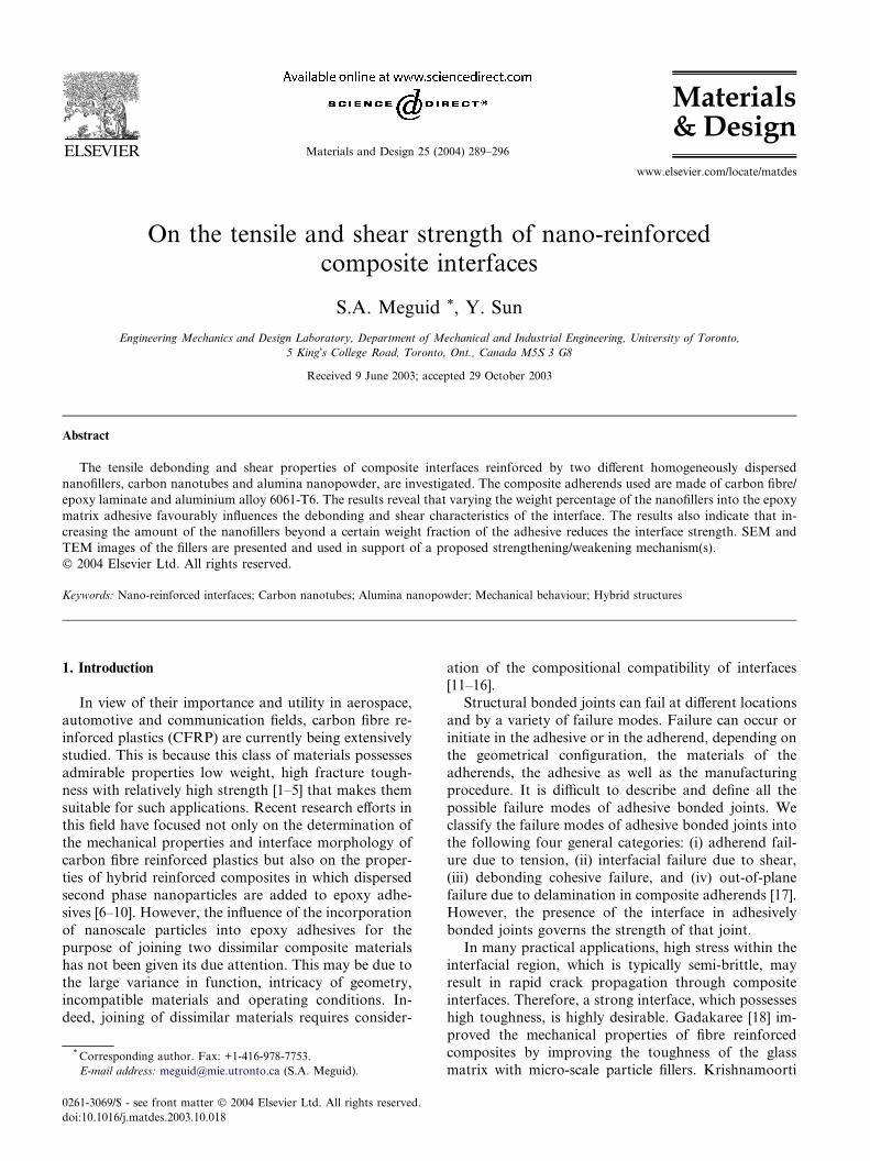
2.1.4. Single walled carbon nanotubes
The manufacturer�s instructions indicate that the rawsingle walled carbon nanotubes were synthesised by the
electric arc technique. In this case, a composite rod
(Ni:Y:C) is vaporised under helium atmosphere. The
pristine material contains SWNTs ropes coexisting with
metallic nanoparticles and other forms of carbon
(graphite, amorphous nanoparticles, nanohorn). The
purification involved the treatment of the carbon na-notubes with nitric acid followed by a cross flow filtra-
tion and an annealing under nitrogen atmosphere at
1600 �C. Fig. 1(a) and (b) show SEM images of single
wall carbon nanotube at two different amplifications. It
can be seen that the nanotubes have diameters between
30 and 60 nm and are a few hundred nanometers long.
The tubes appear like ropes, which will be homoge-
neously dispersed and embedded in the epoxy adhesivesupon proper mixing.
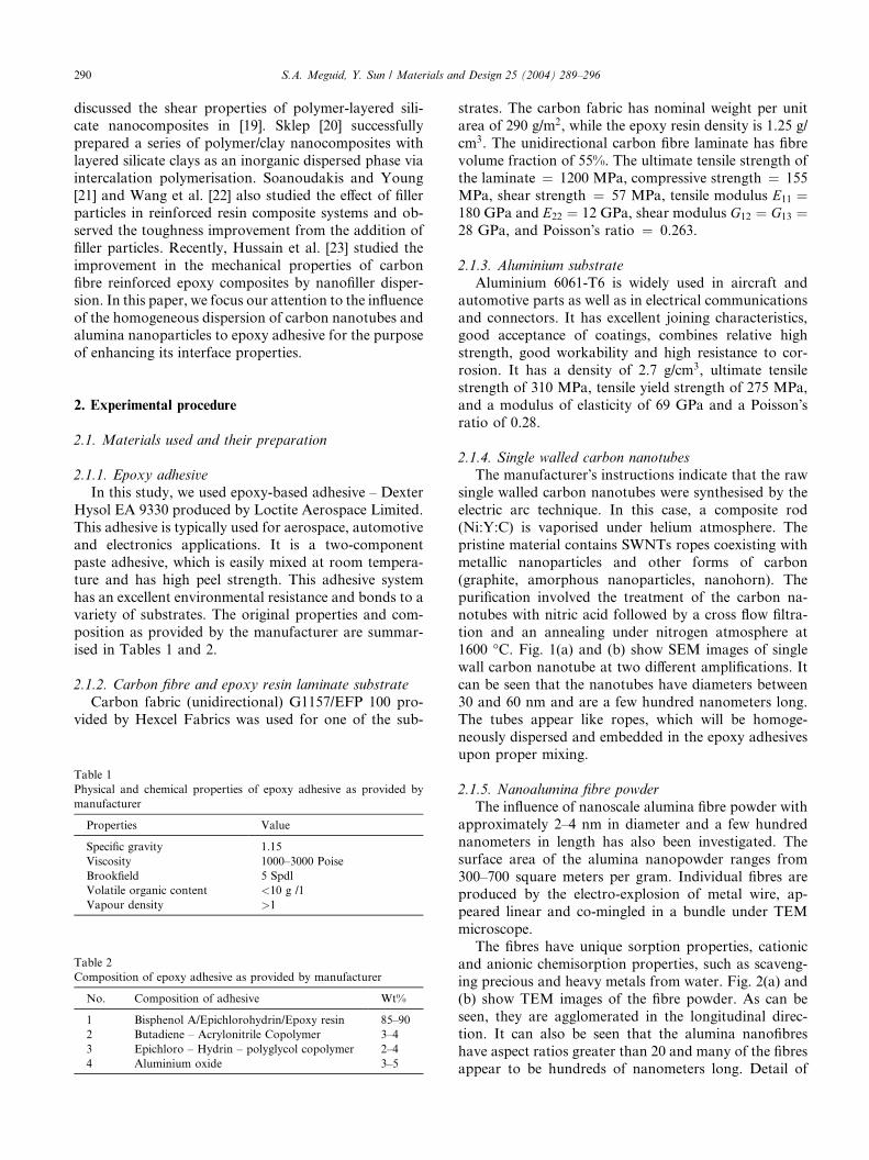
2.1.5. Nanoalumina fibre powder
The influence of nanoscale alumina fibre powder with
approximately 2–4 nm in diameter and a few hundred
nanometers in length has also been investigated. The
surface area of the alumina nanopowder ranges from
300–700 square meters per gram. Individual fibres areproduced by the electro-explosion of metal wire, ap-
peared linear and co-mingled in a bundle under TEM
microscope.
The fibres have unique sorption properties, cationic
and anionic chemisorption properties, such as scaveng-
ing precious and heavy metals from water. Fig. 2(a) and
(b) show TEM images of the fibre powder. As can be
seen, they are agglomerated in the longitudinal direc-tion. It can also be seen that the alumina nanofibres
have aspect ratios greater than 20 and many of the fibres
appear to be hundreds of nanometers long. Detail of
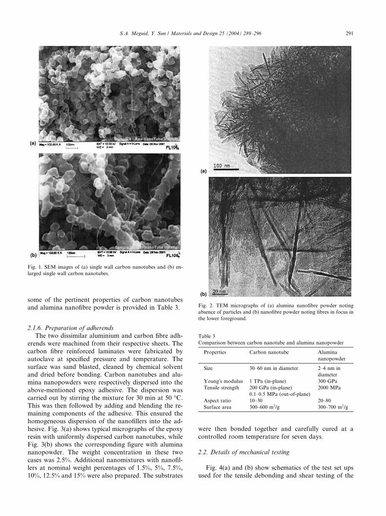
Fig. 2. TEM micrographs of (a) alumina nanofibre powder noting
Fig. 1. SEM images of (a) single wall carbon nanotubes and (b) en-
larged single wall carbon nanotubes.
S.A. Meguid, Y. Sun / Materials and Design 25 (2004) 289–296 291
some of the pertinent properties of carbon nanotubesand alumina nanofibre powder is provided in Table 3.
Table 3
Comparison between carbon nanotube and alumina nanopowder
Properties Carbon nanotube Alumina
nanopowder
Size 30–60 nm in diameter 2–4 nm in
diameter
Young�s modulus 1 TPa (in-plane) 300 GPa
Tensile strength 200 GPa (in-plane)
0.1–0.5 MPa (out-of-plane)
2000 MPa
Aspect ratio 10–30 20–80
Surface area 300–600 m2/g 300–700 m2/g
absence of particles and (b) nanofibre powder noting fibres in focus in
the lower foreground.
2.1.6. Preparation of adherends
The two dissimilar aluminium and carbon fibre adh-
erends were machined from their respective sheets. The
carbon fibre reinforced laminates were fabricated by
autoclave at specified pressure and temperature. The
surface was sand blasted, cleaned by chemical solventand dried before bonding. Carbon nanotubes and alu-
mina nanopowders were respectively dispersed into the
above-mentioned epoxy adhesive. The dispersion was
carried out by stirring the mixture for 30 min at 50 �C.This was then followed by adding and blending the re-
maining components of the adhesive. This ensured the
homogeneous dispersion of the nanofillers into the ad-
hesive. Fig. 3(a) shows typical micrographs of the epoxyresin with uniformly dispersed carbon nanotubes, while
Fig. 3(b) shows the corresponding figure with alumina
nanopowder. The weight concentration in these two
cases was 2.5%. Additional nanomixtures with nanofil-
lers at nominal weight percentages of 1.5%, 5%, 7.5%,
10%, 12.5% and 15% were also prepared. The substrates
were then bonded together and carefully cured at a
controlled room temperature for seven days.
2.2. Details of mechanical testing
Fig. 4(a) and (b) show schematics of the test set ups
used for the tensile debonding and shear testing of the
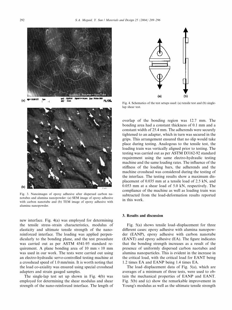
Fig. 3. Nanoimages of epoxy adhesive after dispersed carbon na-
notubes and alumina nanopowder: (a) SEM image of epoxy adhesive
with carbon nanotube and (b) TEM image of epoxy adhesive with
alumina nanopowder.
Fig. 4. Schematics of the test setups used: (a) tensile test and (b) single-
lap shear test.
292 S.A. Meguid, Y. Sun / Materials and Design 25 (2004) 289–296
new interface. Fig. 4(a) was employed for determining
the tensile stress–strain characteristics, modulus of
elasticity and ultimate tensile strength of the nano-
reinforced interface. The loading was applied perpen-
dicularly to the bonding plane, and the test procedure
was carried out as per ASTM 4541-95 standard re-
quirement. A plane bonding area of 10 mm� 10 mmwas used in our work. The tests were carried out using
an electro-hydraulic servo-controlled testing machine at
a crosshead speed of 1.0 mm/min. It is worth noting that
the load co-axiality was ensured using special crosshead
adapters and strain gauged samples.
The single-lap test set up shown in Fig. 4(b) was
employed for determining the shear modulus and shear
strength of the nano-reinforced interface. The length of
overlap of the bonding region was 12.7 mm. The
bonding area had a constant thickness of 0.1 mm and a
constant width of 25.4 mm. The adherends were securely
tightened to an adapter, which in turn was secured in the
grips. This arrangement ensured that no slip would take
place during testing. Analogous to the tensile test, the
loading train was vertically aligned prior to testing. Thetesting was carried out as per ASTM D3162-92 standard
requirement using the same electro-hydraulic testing
machine and the same loading rates. The influence of the
stiffness of the loading bars, the adherends and the
machine crosshead was considered during the testing of
the interface. The testing results show a maximum dis-
placement of 0.035 mm at a tensile load of 2.5 kN, and
0.053 mm at a shear load of 5.0 kN, respectively. Thecompliance of the machine as well as loading train was
subtracted from the load-deformation results reported
in this work.
3. Results and discussion
Fig. 5(a) shows tensile load–displacement for threedifferent cases: epoxy adhesive with alumina nanopow-
der (EANP), epoxy adhesive with carbon nanotube
(EANT) and epoxy adhesive (EA). The figure indicates
that the bonding strength increases as a result of the
presence of uniformly dispersed carbon naotubes and
alumina nanoparticles. This is evident in the increase in
the critical load, with the critical load for EANT being
1.2 times EA and EANP being 1.4 times EA.The load–displacement data of Fig. 5(a), which are
averages of a minimum of three tests, were used to ob-
tain the mechanical properties of EANP and EANT.
Fig. 5(b) and (c) show the remarkable improvement in
Young�s modulus as well as the ultimate tensile strength
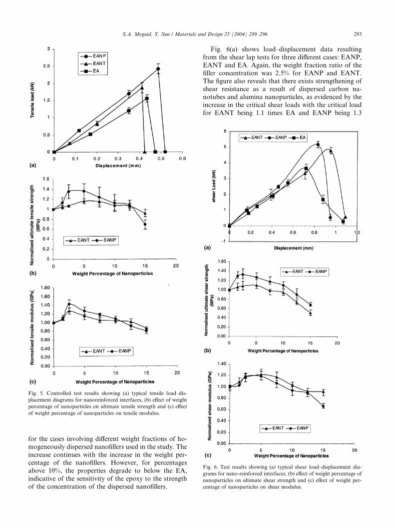
Fig. 6. Test results showing (a) typical shear load–displacement dia-
grams for nano-reinforced interfaces, (b) effect of weight percentage of
nanoparticles on ultimate shear strength and (c) effect of weight per-
centage of nanoparticles on shear modulus.
Fig. 5. Controlled test results showing (a) typical tensile load–dis-
placement diagrams for nanoreinforced interfaces, (b) effect of weight
percentage of nanoparticles on ultimate tensile strength and (c) effect
of weight percentage of nanoparticles on tensile modulus.
S.A. Meguid, Y. Sun / Materials and Design 25 (2004) 289–296 293
for the cases involving different weight fractions of ho-
mogeneously dispersed nanofillers used in the study. The
increase continues with the increase in the weight per-
centage of the nanofillers. However, for percentages
above 10%, the properties degrade to below the EA,
indicative of the sensitivity of the epoxy to the strength
of the concentration of the dispersed nanofillers.
Fig. 6(a) shows load–displacement data resulting
from the shear lap tests for three different cases: EANP,
EANT and EA. Again, the weight fraction ratio of the
filler concentration was 2.5% for EANP and EANT.
The figure also reveals that there exists strengthening ofshear resistance as a result of dispersed carbon na-
notubes and alumina nanoparticles, as evidenced by the
increase in the critical shear loads with the critical load
for EANT being 1.1 times EA and EANP being 1.3
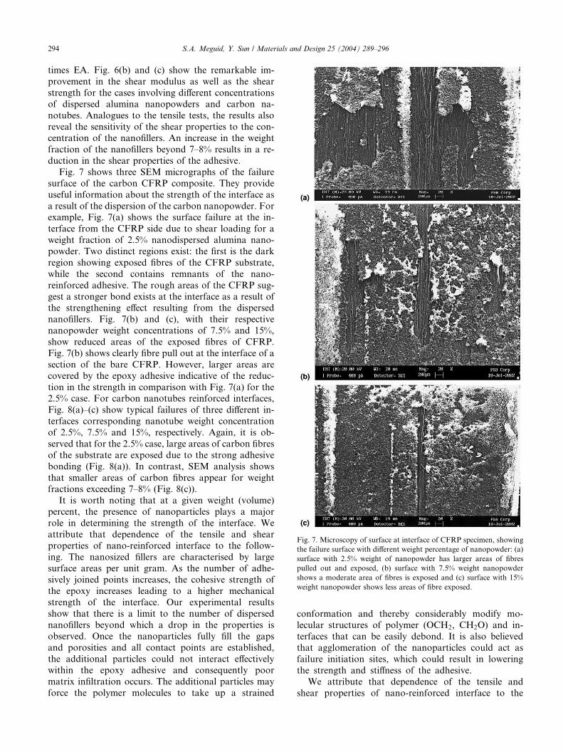
Fig. 7. Microscopy of surface at interface of CFRP specimen, showing
the failure surface with different weight percentage of nanopowder: (a)
surface with 2.5% weight of nanopowder has larger areas of fibres
pulled out and exposed, (b) surface with 7.5% weight nanopowder
shows a moderate area of fibres is exposed and (c) surface with 15%
weight nanopowder shows less areas of fibre exposed.
294 S.A. Meguid, Y. Sun / Materials and Design 25 (2004) 289–296
times EA. Fig. 6(b) and (c) show the remarkable im-
provement in the shear modulus as well as the shear
strength for the cases involving different concentrations
of dispersed alumina nanopowders and carbon na-
notubes. Analogues to the tensile tests, the results alsoreveal the sensitivity of the shear properties to the con-
centration of the nanofillers. An increase in the weight
fraction of the nanofillers beyond 7–8% results in a re-
duction in the shear properties of the adhesive.
Fig. 7 shows three SEM micrographs of the failure
surface of the carbon CFRP composite. They provide
useful information about the strength of the interface as
a result of the dispersion of the carbon nanopowder. Forexample, Fig. 7(a) shows the surface failure at the in-
terface from the CFRP side due to shear loading for a
weight fraction of 2.5% nanodispersed alumina nano-
powder. Two distinct regions exist: the first is the dark
region showing exposed fibres of the CFRP substrate,
while the second contains remnants of the nano-
reinforced adhesive. The rough areas of the CFRP sug-
gest a stronger bond exists at the interface as a result ofthe strengthening effect resulting from the dispersed
nanofillers. Fig. 7(b) and (c), with their respective
nanopowder weight concentrations of 7.5% and 15%,
show reduced areas of the exposed fibres of CFRP.
Fig. 7(b) shows clearly fibre pull out at the interface of a
section of the bare CFRP. However, larger areas are
covered by the epoxy adhesive indicative of the reduc-
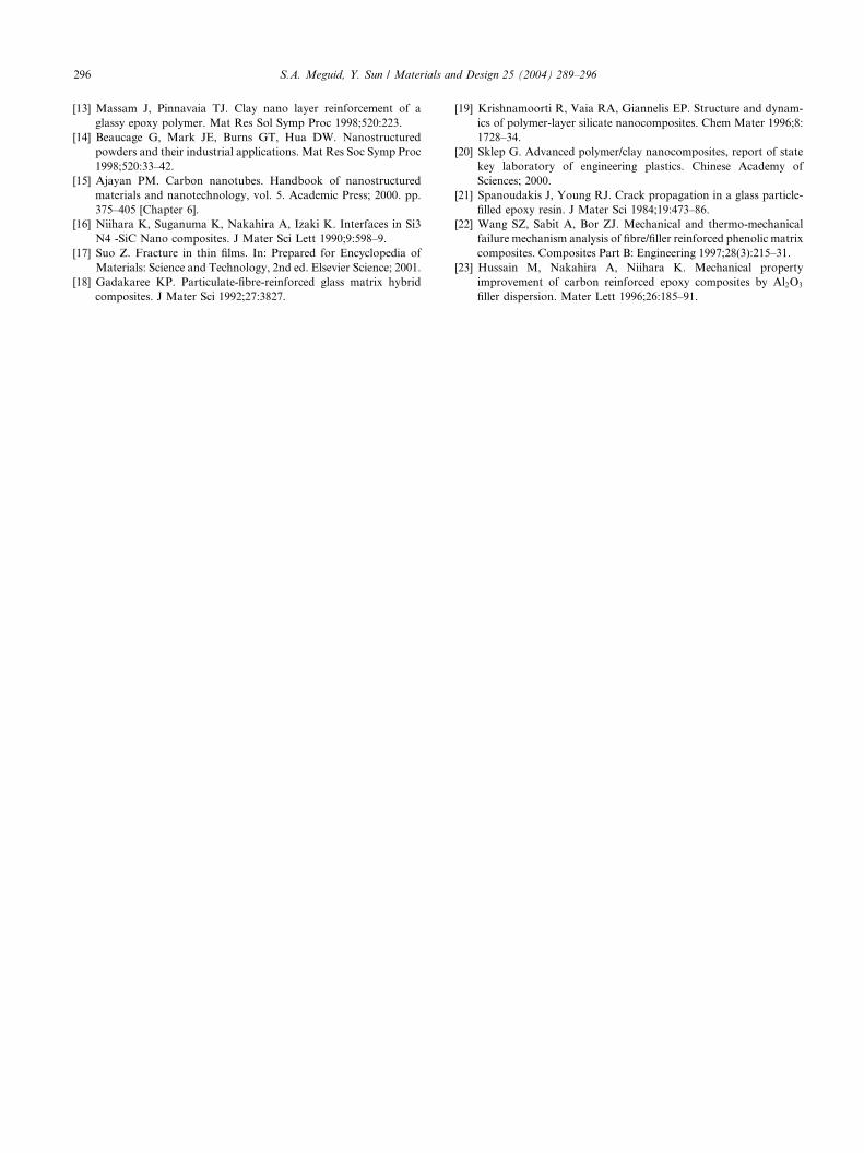
tion in the strength in comparison with Fig. 7(a) for the2.5% case. For carbon nanotubes reinforced interfaces,
Fig. 8(a)–(c) show typical failures of three different in-
terfaces corresponding nanotube weight concentration
of 2.5%, 7.5% and 15%, respectively. Again, it is ob-
served that for the 2.5% case, large areas of carbon fibres
of the substrate are exposed due to the strong adhesive
bonding (Fig. 8(a)). In contrast, SEM analysis shows
that smaller areas of carbon fibres appear for weightfractions exceeding 7–8% (Fig. 8(c)).
It is worth noting that at a given weight (volume)
percent, the presence of nanoparticles plays a major
role in determining the strength of the interface. We
attribute that dependence of the tensile and shear
properties of nano-reinforced interface to the follow-
ing. The nanosized fillers are characterised by large
surface areas per unit gram. As the number of adhe-sively joined points increases, the cohesive strength of
the epoxy increases leading to a higher mechanical
strength of the interface. Our experimental results
show that there is a limit to the number of dispersed
nanofillers beyond which a drop in the properties is
observed. Once the nanoparticles fully fill the gaps
and porosities and all contact points are established,
the additional particles could not interact effectivelywithin the epoxy adhesive and consequently poor
matrix infiltration occurs. The additional particles may
force the polymer molecules to take up a strained
conformation and thereby considerably modify mo-lecular structures of polymer (OCH2, CH2O) and in-
terfaces that can be easily debond. It is also believed
that agglomeration of the nanoparticles could act as
failure initiation sites, which could result in lowering
the strength and stiffness of the adhesive.
We attribute that dependence of the tensile and
shear properties of nano-reinforced interface to the
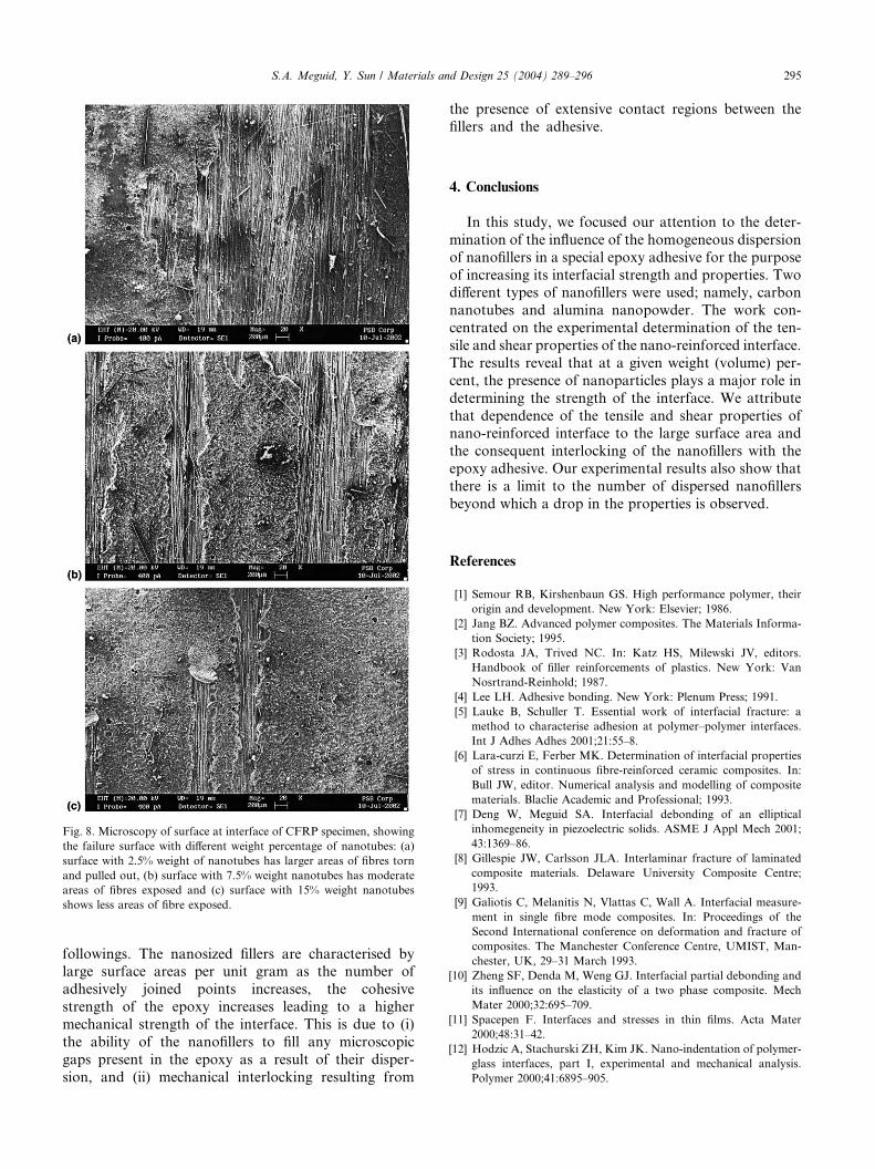
Fig. 8. Microscopy of surface at interface of CFRP specimen, showing
the failure surface with different weight percentage of nanotubes: (a)
surface with 2.5% weight of nanotubes has larger areas of fibres torn
and pulled out, (b) surface with 7.5% weight nanotubes has moderate
areas of fibres exposed and (c) surface with 15% weight nanotubes
shows less areas of fibre exposed.
S.A. Meguid, Y. Sun / Materials and Design 25 (2004) 289–296 295
followings. The nanosized fillers are characterised bylarge surface areas per unit gram as the number of
adhesively joined points increases, the cohesive
strength of the epoxy increases leading to a higher
mechanical strength of the interface. This is due to (i)
the ability of the nanofillers to fill any microscopic
gaps present in the epoxy as a result of their disper-
sion, and (ii) mechanical interlocking resulting from
the presence of extensive contact regions between the
fillers and the adhesive.
4. Conclusions
In this study, we focused our attention to the deter-
mination of the influence of the homogeneous dispersion
of nanofillers in a special epoxy adhesive for the purpose
of increasing its interfacial strength and properties. Twodifferent types of nanofillers were used; namely, carbon
nanotubes and alumina nanopowder. The work con-
centrated on the experimental determination of the ten-
sile and shear properties of the nano-reinforced interface.
The results reveal that at a given weight (volume) per-
cent, the presence of nanoparticles plays a major role in
determining the strength of the interface. We attribute
that dependence of the tensile and shear properties ofnano-reinforced interface to the large surface area and
the consequent interlocking of the nanofillers with the
epoxy adhesive. Our experimental results also show that
there is a limit to the number of dispersed nanofillers
beyond which a drop in the properties is observed.
References
[1] Semour RB, Kirshenbaun GS. High performance polymer, their
origin and development. New York: Elsevier; 1986.
[2] Jang BZ. Advanced polymer composites. The Materials Informa-
tion Society; 1995.
[3] Rodosta JA, Trived NC. In: Katz HS, Milewski JV, editors.
Handbook of filler reinforcements of plastics. New York: Van
Nosrtrand-Reinhold; 1987.
[4] Lee LH. Adhesive bonding. New York: Plenum Press; 1991.
[5] Lauke B, Schuller T. Essential work of interfacial fracture: a
method to characterise adhesion at polymer–polymer interfaces.
Int J Adhes Adhes 2001;21:55–8.
[6] Lara-curzi E, Ferber MK. Determination of interfacial properties
of stress in continuous fibre-reinforced ceramic composites. In:
Bull JW, editor. Numerical analysis and modelling of composite
materials. Blaclie Academic and Professional; 1993.
[7] Deng W, Meguid SA. Interfacial debonding of an elliptical
inhomegeneity in piezoelectric solids. ASME J Appl Mech 2001;
43:1369–86.
[8] Gillespie JW, Carlsson JLA. Interlaminar fracture of laminated
composite materials. Delaware University Composite Centre;
1993.
[9] Galiotis C, Melanitis N, Vlattas C, Wall A. Interfacial measure-
ment in single fibre mode composites. In: Proceedings of the
Second International conference on deformation and fracture of
composites. The Manchester Conference Centre, UMIST, Man-
chester, UK, 29–31 March 1993.
[10] Zheng SF, Denda M, Weng GJ. Interfacial partial debonding and
its influence on the elasticity of a two phase composite. Mech
Mater 2000;32:695–709.
[11] Spacepen F. Interfaces and stresses in thin films. Acta Mater
2000;48:31–42.
[12] Hodzic A, Stachurski ZH, Kim JK. Nano-indentation of polymer-
glass interfaces, part I, experimental and mechanical analysis.
Polymer 2000;41:6895–905.
296 S.A. Meguid, Y. Sun / Materials and Design 25 (2004) 289–296
[13] Massam J, Pinnavaia TJ. Clay nano layer reinforcement of a
glassy epoxy polymer. Mat Res Sol Symp Proc 1998;520:223.
[14] Beaucage G, Mark JE, Burns GT, Hua DW. Nanostructured
powders and their industrial applications. Mat Res Soc Symp Proc
1998;520:33–42.
[15] Ajayan PM. Carbon nanotubes. Handbook of nanostructured
materials and nanotechnology, vol. 5. Academic Press; 2000. pp.
375–405 [Chapter 6].
[16] Niihara K, Suganuma K, Nakahira A, Izaki K. Interfaces in Si3
N4 -SiC Nano composites. J Mater Sci Lett 1990;9:598–9.
[17] Suo Z. Fracture in thin films. In: Prepared for Encyclopedia of
Materials: Science and Technology, 2nd ed. Elsevier Science; 2001.
[18] Gadakaree KP. Particulate-fibre-reinforced glass matrix hybrid
composites. J Mater Sci 1992;27:3827.
[19] Krishnamoorti R, Vaia RA, Giannelis EP. Structure and dynam-
ics of polymer-layer silicate nanocomposites. Chem Mater 1996;8:
1728–34.
[20] Sklep G. Advanced polymer/clay nanocomposites, report of state
key laboratory of engineering plastics. Chinese Academy of
Sciences; 2000.
[21] Spanoudakis J, Young RJ. Crack propagation in a glass particle-
filled epoxy resin. J Mater Sci 1984;19:473–86.
[22] Wang SZ, Sabit A, Bor ZJ. Mechanical and thermo-mechanical
failure mechanism analysis of fibre/filler reinforced phenolic matrix
composites. Composites Part B: Engineering 1997;28(3):215–31.
[23] Hussain M, Nakahira A, Niihara K. Mechanical property
improvement of carbon reinforced epoxy composites by Al2O3
filler dispersion. Mater Lett 1996;26:185–91.