on the singular stresses at an interface corner
TRANSCRIPT
Z c • . & ttc • . & . . & t/e • . [ c ttc
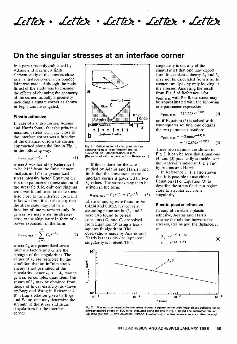
On the singular stresses at an interface corner In a paper recently published by Adams and Harris 1, a finite element study of the stresses close to an interface comer in a bonded joint was made. Although the main thrust of the study was to consider the effects of changing the geometry of the comer, initially a geometry including a square comer as shown in Fig. 1 was investigated.
Elastic adhesive
In case o f a sharp corner, Adams and Harris found that the principal m a x i m u m s t r e s s , O'prin" m a x , c l o s e tO
the interface corner was a function of the distance, r, from the comer, approached along the line in Fig. l, in the following way:
Gpr in . max = Cr-2 (1)
where a was found by Reference 1 to be 0.185 from the finite element analysis and C is a generalized stress intensity factor. Equation (1) is a one-parameter representation of the stress field, ie, only one singular term was found to control the stress field close to the interface comer. It is known from linear elasticity that the stress state may not be a function of one parameter only. In general we may write the stresses close to the singularity in form of a power expansion in the form:
oC
= ~ Ck r-;vk (2) Gprin . m a x
k = l
where Ck are generalized stress intensity factors and Ak are the strength of the singularities. The values of Ak are restricted by the condition that an infinite strain energy is not permitted at the singularity, hence Ak < 1. Ak may in general be complex quantities. The values of Ak may be obtained from theory of linear elasticity, as shown by Bogy and Wang in Reference 2. By using a relation given by Bogy and Wang, one may determine the strength of the stress and strain singularities for the interface corner.
a
, ~ ' 1 . 4 6 - - e
~ . Rgd ~ ,~": i!ili!i!:.. !
.t 012s ~ . i : i . i : i . , "
~ A l u m i n i u m l ~ : ~
b Uniform loading
Fig. 1 Critical region of a lap joint with an adhesive fillet: (a) load transfer; and (b) simplified joint. All dimensions in ram. (Reproduced with permission from Reference 1 )
I f this is done for the case studied by Adams and Harris 1, one finds that the stress state at the interface comer is governed by two ,a. k values. The stresses may then be written in the form:
O'prin, m ax = C1 r-X~ + C2 r-z2 (3)
where Al and A2 were found to be 0.4234 and 0.2052, respectively, assuming plane strain. (A1 and A 2 were also found to be real constants.) Ci and C2 are solved from Equation (3) using a least- squares fit algorithm. The observations made by Adams and Harris is that only one "apparent' singularity is noticed. This
103
singularity is not any of the singularities that one may expect from linear elastic theory. ,aq and A2 may not be calculated from a finite element analysis by only looking at the stresses. Analysing the result from Fig. 5 of Reference 1 for O'prin. max with 0 = 0, the stress may be approximated with the following one-parameter expression:
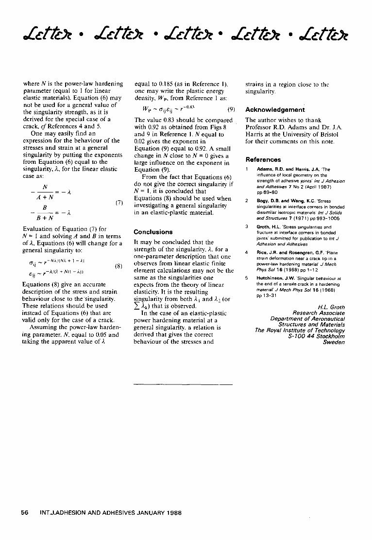
O'prin. max = 115.268r -°A85 (4)
or, if Equation (3) is solved with a least-squares routine, one obtains the two-parameter relation:
O'win , max = - - 2.666r-°4234
+ 112.862r -°2°52 (5)
These two relations are shown in Fig. 2. It can be seen that Equations (4) and (5) practically coincide over the r-interval studied in Fig. 2 and by Adams and Harris.
In Reference 3. it is also shown that it is possible to use either Equation (1) or Equation (3) to describe the stress field in a region close to an interface corner singularity.
Elastic-plastic adhesive In case of an elastic-plastic adhesive, Adams and Harris 1 assume the relation between the stresses, strains and the distance, r, a s ;
O.ij ~ r -N/ ( I + N) (6)
e i j ~ r - 1 / ( l + N )
a .
E .E
A~B
1 0 ~ i I | J | i I I I I I | i I | i l l I | J | i J I !
10-4 10-3 10-2 10-1 r (mm)
Fig. 2 Maximum principal adhesive stress around a square corner with linear elastic adhesive for an average applied stress of 100 MPa, evaluated along the line in Fig. 1 (a): (A) one-parameter relation, Equation (4); and (B) two-parameter relation, Equation (5). The two curves coincide in the r-interval
INT.J.ADHESION AND ADHESIVES JANUARY 1988 55
Zcttc • • Zcttc . Zcttc • Zcttc
where N is the power-law hardening parameter (equal to 1 for linear elastic materials). Equation (6) may not be used for a general value of the singularity strength, as it is derived for the special case of a crack, cf References 4 and 5.
One may easily find an expression for the behaviour of the stresses and strain at a general singularity by putting the exponents from Equation (6) equal to the singularity, A, for the linear elastic case as:
N
A + N (7)
B
B + N
Evaluation of Equation (7) for N = I and solving A and B in terms of),, Equations (6) will change for a general singularity to:
Gi j ~ r - N A / ( N A + I - A) (8)
c.ij ~ r - A / ( A + N(I - k ) )
Equations (8) give an accurate description of the stress and strain behaviour close to the singularity. These relations should be used instead of Equations (6) that are valid only for the case of a crack.
Assuming the power-law harden- ing parameter, N, equal to 0.05 and taking the apparent value of A
equal to 0.185 (as in Reference 1), one may write the plastic energy density, Wp, from Reference ! as:
W p ~ tTijSij ~ r -0"83 (9)
The value 0.83 should be compared with 0.92 as obtained from Figs 8 and 9 in Reference 1. N equal to 0.02 gives the exponent in Equation (9) equal to 0.92. A small change in N close to N = 0 gives a large influence on the exponent in Equation (9).
From the fact that Equations (6) do not give the correct singularity if N = 1, it is concluded that Equations (8) should be used when investigating a general singularity in an elastic-plastic material.
Conclusions It may be concluded that the strength of the singularity, A, for a one-parameter description that one observes from linear elastic finite element calculations may not be the same as the singularities one expects from the theory of linear elasticity. It is the resulting singularity from both A i and A2 (or
kk) that is observed. In the case of an elastic-plastic
power hardening material at a general singularity, a relation is derived that gives the correct behaviour of the stresses and
strains in a region close to the singularity.
Acknowledgement
The author wishes to thank Professor R.D. Adams and Dr. J.A. Harris at the. University of Bristol for their comments on this note.
References 1 Adams, R.D. and Harris, J.A. 'The
influence of local geometry on the strength of adhesive joints' Int J Adhesion and Adhesives 7 No 2 (April 1987) pp 69-80
Bogy, D.B. and Wang, K.C. 'Stress singularities at interface corners in bonded dissimilar isotropic materials'/nt J Solids and Structures 7 (1971 ) pp 993 -1005
3 Groth, H.L. 'Stress singularities and fracture at interface corners in bonded joints' submitted for publication to Int J Adhesion and Adhesives
Rice, J.R. and Rosengren, G.F. 'Plane strain deformation near a crack tip in a power-law hardening material' J Mech Phys Sol 16 (1968) pp 1-12
Hutchinson, J.W. 'Singular behsviour at the end of a tensile crack in a hardening material' J Mech Phys Sol 16 (1968) pp 13-31
H.L Groth Research Associate
Department of Aeronautical Structures and Materials
The Royal Institute of Technology S- 100 44 Stockholm
Sweden
56 INT.J.ADHESION AND ADHESIVES JANUARY 1988