on obtaining the young modulus from numerical analysis of ... 4 18.pdf · obtaining the young’s...
TRANSCRIPT
http://www.revmaterialeplastice.ro MATERIALE PLASTICE ♦ 55♦ No. 4 ♦ 2018712
On Obtaining the Young Modulus from Numerical Analysis ofComposite Material Constituent
SORIN DRAGHICI1, HORIA ALEXANDRU PETRESCU1*, ANTON HADAR1,2
1University Politehnica of Bucharest, Department of Strength of Materials, 313 Splaiul Independentei, 060032, Bucharest, Romania2Academy of Romanian Scientists, 54 Splaiul Independentei, 050094, Bucharest, Romania
Importance and use of composite materials are no longer a subject that should be emphasized. They offera successful replacement for classical materials in most areas of engineering, conferring similar elastic-mechanical properties to metal or non-metal alloys with several advantages such as reduced mass, chemicalresistance etc. Considering this, knowledge of the elastic-mechanical characteristics is of utmost importance.The present article aims to create a finite element model that can predict the longitudinal elastic modulusof a double-layered composite material based on the elastic characteristics of its constituents. For this, theelastic characteristics of the constituents were determined, then used in the finite element analysis thusobtaining the Young’s modulus for the numerical composite material. Also, the longitudinal elastic modulusof the resultant composite was determined experimentally. The results of the finite element model werecompared with experimental values.
Keywords: composites, fiberglass, Young’s modulus, FEM
In recent years, detailed analyses and experimentsregarding the behavioural pattern of composite materialstook a turn for faster and cheaper mechanicalcharacterization. Previous methods consisted only ofexpensive and time-consuming experimental methods forobtaining the elastic characteristics of compositematerials. A numerical approach, such as finite elementmodelling (FEM), offers faster, cheaper and more detailedresults for an infinite number of composite materialsconfigurations.
A series of relatively simple mechanical tests were usedto evaluate the properties of the material considered. Theresults are used in engineering design and as a basis forcomparing and selecting materials. This approach ispresented in paper [1], inferring proper results for tree pointbending numerical simulation compared to experimentalsets. Dian-sen Li et al., present a parameterized finiteelement model [2] established for 3-Dimensional five-directional rectangular braided composite. A prediction ofthe effective elastic properties and the meso-scalemechanical response been presented to verify the validationof the FEM.
Stiffness degradation and failure morphologies obtainedfrom the FEM results were presented in paper [3]. The stressdistributions, stress hysteresis and failures of fibre towsand resins at different parts of the 3-D braided compositematerial have been collected from the FEM calculations toanalyse the fatigue failure mechanisms.
The strategy presented in this paper is conceived withthe aim of avoiding some of the numerical problemscommonly encountered using most of the methodologiesproposed in the literature for the mesoscale modelling ofceramic woven composites [4].
A good foundation for a successful FEM analysis consistsin proper boundary conditions. A detailed approach ispresented in the work [5] of S. Jaques et al. by creating amethod for the construction of meso-scale FE models oftextile reinforced composites using periodic boundaryconditions on multiple part meshes. These practices canbe applied even on more complex structures such assandwich panels as presented in paper [6].
email: [email protected]; Phone: +40727990695
In analogy with the experimental methods presented inthe work [7] of Siddiqui, M. Z., Tariq, F. et al., for compositelaminates, the Young’s modulus (E), is termed as a quantityfor the chord modulus as presented in figure 1, and iscalculated as:
(1)
where:E is the chord modulus as defined in figure 1;P-u is the tensile load at the upper strain limit;Pl - is the tensile load at the lower strain limit;εu is the upper strain limit;εl is the lower strain limit;A is the transversal area of the specimen.In general, the tensile test is performed to evaluate the
elastic constants, the strength, the ductility, and the strainhardening of the materials. The modulus of elasticity, E, isdetermined as a measure of rigidity, the yield strength limit,σy, and the tensile strength, σt [8].
Detailed information regarding the tensile tests oncomposite materials is presented in paper [9], approachingthe experiment at a macro scale of the composite material.A micro scale inquiry is presented in the work [10] of Li, J.,Jiao et al., not the subject of current paper but a forecast of
Fig.1. The slope of dotted line is the chord modulus [7]

http://www.revmaterialeplastice.roMATERIALE PLASTICE ♦ 55♦ No. 4 ♦ 2018 713
further investigations. A closer approach to our currentinterest is presented in paper [11].
Papers from Kabelka [12], Woo et al. [13], Sankar andMarrey [14] presented solutions for 2D analyses of plainweave composites using the assumption of plain-strainstate, but these models are not suitable for correctlymodelling textile composites.
Considering all of the above, the authors could establisha proper protocol for creating a 3D model and obtainingthe Young’s modulus for a fibreglass reinforced polymercomposite material. At first, the experimental data, suchas the strain-stress curves and Young’s modulus, wereobtained the constituents (fibreglass yarn and polymermatrix) and for a double layered composite. Constituentdata was used for creating a finite element model and thecomposite data was used for validation of the numericalmodel.
Experimental partMechanical tests to determine strain-stress were
performed on the Instron 8801 Universal Test Machine, thusevaluating five double layered samples for the longitudinaldirection as shown in figure 2 [8].
Fig. 2. Two-layer composite specimens for longitudinaldirection
Fig. 3. Characteristic curves obtained for fibreglass-polyesterresin with two layers in the longitudinal direction
The results obtained were presented in figure 3 and intable 1. All calculations were machine performed such noalteration could be possible.
For the analytical calculation necessary to determinethe Young’s modulus for the constituents. A total of fivepolyester resin (fig. 4.a) and five fiberglass yarns samples(fig. 4.c) were prepared. All tests were performed on theInstron 8872 universal testing machine, using a strain gaugeas depicted in figures 4.b and 4.d. Four aluminium plates,two on each end of the fibreglass yarn, with a 50 mmseparation were used in order to attach the strain gauge.
Table 1EXPERIMENTAL DATA FOR THE TWO LAYERED FIBREGLASS-
POLYESTER RESIN COMPOSITE
Fig. 4. The specimens and setupfor experimental determination on
constituents
a. Resin specimensb.Experimental setup for resin
c. Fiberglass specimens
d. Experimental setup for
fiberglass
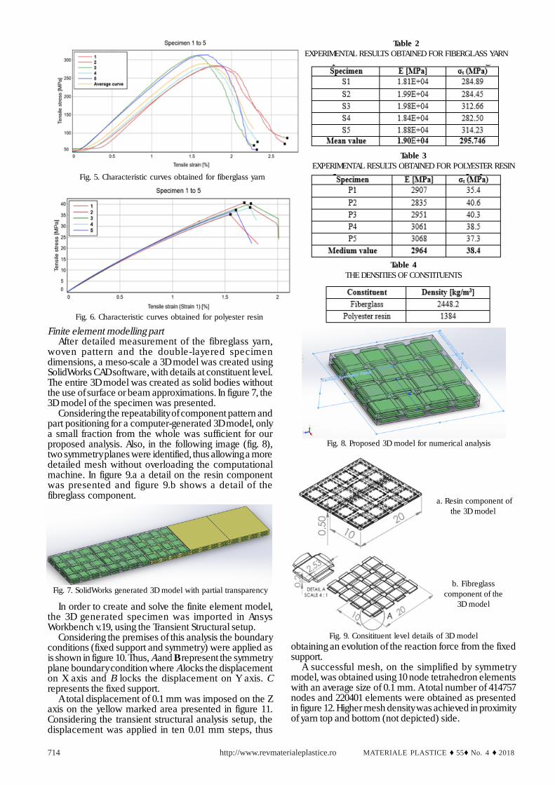
Figure 5 presents the strain-stress curve for the fibreglassyarn. The prestress difference between filaments, causedby the used aluminium brackets, generates smalldifferences in tensile strength and strain origin for eachspecimen. These differences, as is shown in table 2, donot generate a large interval of data for the mean Young’smodulus or tensile strength.
Tensile test results for the polyester resin presented infigure 6, almost overlap, thus asserting consistency insample manufacturing and polymerization time. Theobtained values for Young’s modulus and tensile strength,presented in table 3, are consistent with the literature.
The density of the two constituents was determined bysample weighing and measuring the sample displacedvolume (table 4).sp
http://www.revmaterialeplastice.ro MATERIALE PLASTICE ♦ 55♦ No. 4 ♦ 2018714
Finite element modelling partAfter detailed measurement of the fibreglass yarn,
woven pattern and the double-layered specimendimensions, a meso-scale a 3D model was created usingSolidWorks CAD software, with details at constituent level.The entire 3D model was created as solid bodies withoutthe use of surface or beam approximations. In figure 7, the3D model of the specimen was presented.
Considering the repeatability of component pattern andpart positioning for a computer-generated 3D model, onlya small fraction from the whole was sufficient for ourproposed analysis. Also, in the following image (fig. 8),two symmetry planes were identified, thus allowing a moredetailed mesh without overloading the computationalmachine. In figure 9.a a detail on the resin componentwas presented and figure 9.b shows a detail of thefibreglass component.
Table 2EXPERIMENTAL RESULTS OBTAINED FOR FIBERGLASS YARN
Fig. 5. Characteristic curves obtained for fiberglass yarn
Fig. 6. Characteristic curves obtained for polyester resin
Table 3EXPERIMENTAL RESULTS OBTAINED FOR POLYESTER RESIN
Table 4THE DENSITIES OF CONSTITUENTS
obtaining an evolution of the reaction force from the fixedsupport.
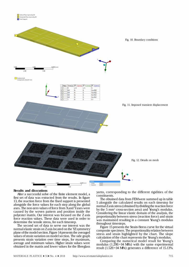
A successful mesh, on the simplified by symmetrymodel, was obtained using 10 node tetrahedron elementswith an average size of 0.1 mm. A total number of 414757nodes and 220401 elements were obtained as presentedin figure 12. Higher mesh density was achieved in proximityof yarn top and bottom (not depicted) side.
Fig. 7. SolidWorks generated 3D model with partial transparency
In order to create and solve the finite element model,the 3D generated specimen was imported in AnsysWorkbench v.19, using the Transient Structural setup.
Considering the premises of this analysis the boundaryconditions (fixed support and symmetry) were applied asis shown in figure 10. Thus, A and B represent the symmetryplane boundary condition where A locks the displacementon X axis and B locks the displacement on Y axis. Crepresents the fixed support.
A total displacement of 0.1 mm was imposed on the Zaxis on the yellow marked area presented in figure 11.Considering the transient structural analysis setup, thedisplacement was applied in ten 0.01 mm steps, thus
Fig. 8. Proposed 3D model for numerical analysis
a. Resin component ofthe 3D model
b. Fibreglasscomponent of the
3D model
Fig. 9. Consitituent level details of 3D model
http://www.revmaterialeplastice.roMATERIALE PLASTICE ♦ 55♦ No. 4 ♦ 2018 715
Results and disscutionsAfter a successful solve of the finite element model, a
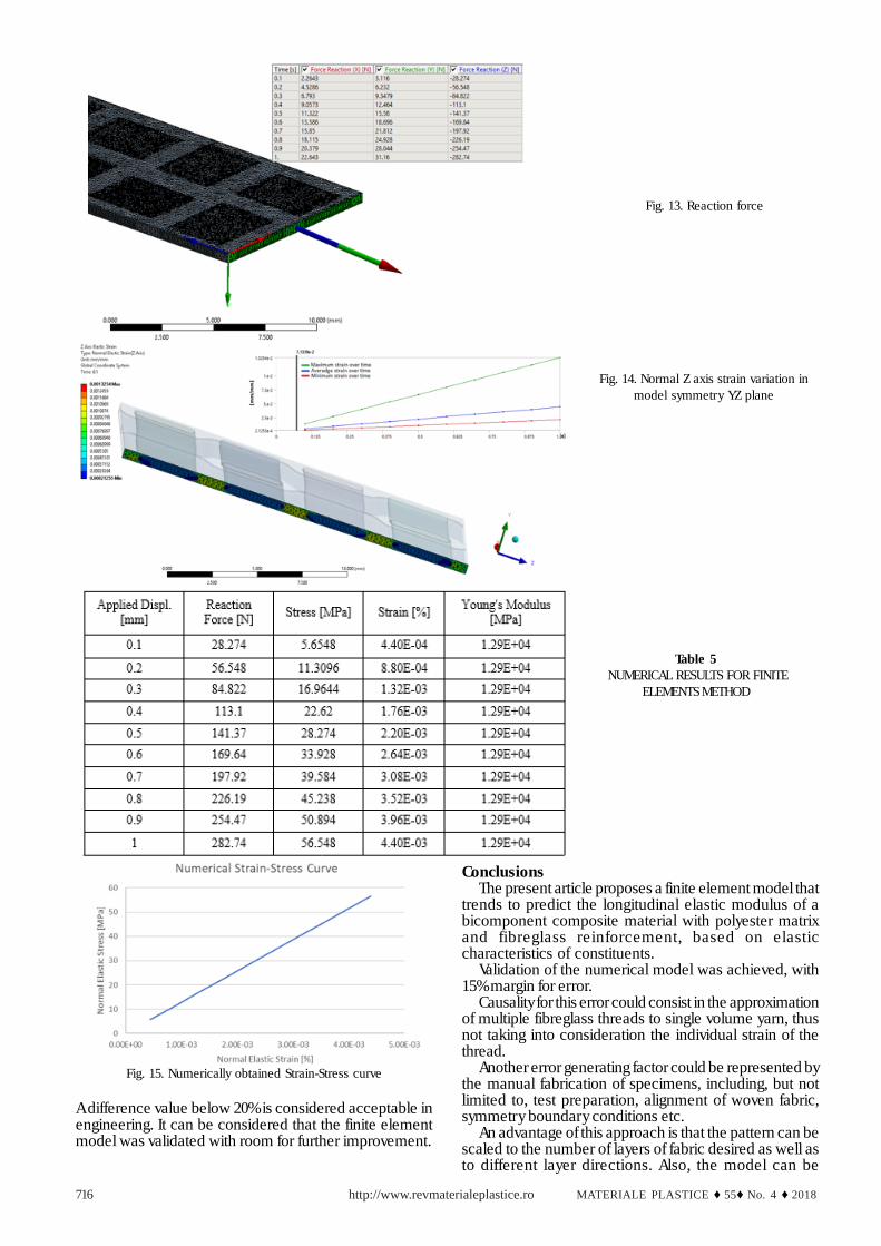
first set of data was extracted from the results. In figure13, the reaction force from the fixed support is presentedalongside the force values for each step along the globalaxes. The non-zero values of force from X and Y axes werecaused by the woven pattern and position inside thepolyester matrix. Our interest was focused on the Z axisforce reaction values. These data were used in order todetermine the tensile stress, for each timestep.
The second set of data to serve our interest was thenormal elastic strain on Z axis located on the YZ symmetryplane of the model section. Figure 14 presents the averagedvalues of strain variation on model section. The side graphpresents strain variation over time steps, for maximum,average and minimum values. Higher strain values wereobtained in the matrix and lower values for the fibreglass
Fig. 10. Boundary conditions
Fig. 11. Imposed transient displacement
Fig. 12. Details on mesh
yarns, corresponding to the different rigidities of theconstituents.
The obtained data from FEM were summed up in table5 alongside the calculated results on each timestep fornormal Z axis stress (obtained by dividing the reaction forceby the 5 mm2 cross-section area) and Young’s modulus.Considering the linear elastic domain of the analysis, theproportionality between stress (reaction force) and strainwas maintained resulting in a constant Young’s modulusthroughout timesteps.
Figure 15 presents the Strain-Stress curve for the virtualcomposite specimen. The proportionality relation betweenstress and strain highlighted by the chart. The slopecalculation of the chart represents the Young’s modulus.
Comparing the numerical model result for Young’smodulus (1.29E+04 MPa) with the same experimentalresult (1.52E+04 MPa) generates a difference of 15.13%.
http://www.revmaterialeplastice.ro MATERIALE PLASTICE ♦ 55♦ No. 4 ♦ 2018716
Table 5 NUMERICAL RESULTS FOR FINITE
ELEMENTS METHOD
Fig. 13. Reaction force
Fig. 14. Normal Z axis strain variation inmodel symmetry YZ plane
Fig. 15. Numerically obtained Strain-Stress curve
A difference value below 20% is considered acceptable inengineering. It can be considered that the finite elementmodel was validated with room for further improvement.
ConclusionsThe present article proposes a finite element model that
trends to predict the longitudinal elastic modulus of abicomponent composite material with polyester matrixand fibreglass reinforcement, based on elasticcharacteristics of constituents.
Validation of the numerical model was achieved, with15% margin for error.
Causality for this error could consist in the approximationof multiple fibreglass threads to single volume yarn, thusnot taking into consideration the individual strain of thethread.
Another error generating factor could be represented bythe manual fabrication of specimens, including, but notlimited to, test preparation, alignment of woven fabric,symmetry boundary conditions etc.
An advantage of this approach is that the pattern can bescaled to the number of layers of fabric desired as well asto different layer directions. Also, the model can be
http://www.revmaterialeplastice.roMATERIALE PLASTICE ♦ 55♦ No. 4 ♦ 2018 717
parameterized so that the volume ratio of fibreglass fabric/polyester resin varies according to the designer’s needs.
Other advantage consists in the possibility ofextrapolating the method to any kind of fabric and resinand could be subject of further research.
Future investigations shall seek to create a modelcapable of predicting all the elastic characteristics requiredin engineering design, starting from the elasticcharacteristics of the constituents. It is also a goal tovalidate the model using the numerical method ofcalculation with finite differences as schematized in [15].
A possible application for this method could be in thearea of vehicle safety and crashworthiness as is presentedin the work [16] of Jiga G. et al.
Acknowledgements: The authors are grateful for all members fromthe INOVABIOMED project, ID: P_36_611:145/26.10.2016, http://www.inovabiomed.upb.ro/ and the University POLITEHNICA ofBucharest for technical support The authors would like to thankeditors and anonymous reviews. This work has been funded byUniversity Politehnica of Bucharest, through the “Excellence ResearchGrants” Program, UPB-GEX 2017, Identifier: UPB-GEX-2017, Projectacronim MCV.
References1. SUN, B., LIU, R., GU, B., Numerical simulation of three-point bendingfatigue of four-step 3-D braided rectangular composite under differentstress levels from unit-cell approach, Computational Materials Science,65, 2012, pp. 239-2462. LI, D.S., FANG, D.N., JIANG, N., XUEFENG, Y., Finite elementmodeling of mechanical properties of 3D five-directional rectangularbraided composites, Composites Part B: Engineering, 42(6), 2011,pp. 1373-13853. WU, L., ZHANG, F., SUN, B., GU, B., Finite element analyses onthree-point low-cyclic bending fatigue of 3-D braided compositematerials at microstructure level, International Journal of MechanicalSciences, 84, 2014, pp. 41-534. FAGIANO, C., GENET, M., BARANGER, E., LADEVÈZE, P.,Computational geometrical and mechanical modeling of wovenceramic composites at the mesoscale, Composite Structures, 112,2014, pp. 146-1565. JACQUES, S., DE BAERE, I., VAN PAEPEGEM, W., Application ofperiodic boundary conditions on multiple part finite element meshes
for the meso-scale homogenization of textile fabric composites,Composites Science and Technology, 92, 2014, pp. 41-546. SADIGHI, M., HOSSEINI, S. A., Finite element simulation andexperimental study on mechanical behavior of 3D woven glass fibercomposite sandwich panels, Composites Part B: Engineering, 55,2013, pp. 158-1667. SIDDIQUI, M.Z., TARIQ, F., NAZ, N., AHMED, M.F., Determination ofYoung’s modulus of metallic and composite materials by digital imagecorrelation, Journal of Space Technology, 1(1), 2012, pp. 32-378. DRAGHICI, S., PARAUSANU, I., BACIU, F., PETRESCU, H.A., HADAR,A., PASTRAMA, S.D., A Comparative Experimental-Numerical Analysison the Vibration Behaviour of a Composite Satellite Subset. Mat.Plast., 53, no. 4, 2016, p. 585-5899. SAVA, M., HADÃR, A., PARAUSANU, I., PETRESCU, H.A., BACIU, F.,STANESCU M.M., Validation of the numerical model of single-layercomposites reinforced with carbon fiber and aramid, In AIPConference Proceedings, Vol. 1738, No. 1, 2016, 48008010. LI, J., JIAO, Y., SUN, Y., WEI, L., Experimental investigation of cut-edge effect on mechanical properties of three-dimensional braidedcomposites, Materials & design, 28(9), 2007, pp. 2417-242411. VERPOEST, I., LOMOV, S.V., Virtual textile composites softwareWiseTex: Integration with micro-mechanical, permeability andstructural analysis, Composites Science and Technology, 65(15-16),2005, pp. 2563-257412. KABELKA, J., Prediction of the Thermal Properties of Fibre-ResinComposites. (Retroactive Coverage), Elsevier Applied SciencePublishers, Ltd., Developments in Reinforced Plastics-III, 1984, pp.167-20213. WHITCOMB, J., WOO, K., GUNDAPANENI, S., Macro finite elementfor analysis of textile composites. Journal of Composite Materials,28(7), 1994, pp. 607-61814. MARREY, R.V., SANKAR, B.V., A micromechanical model for textilecomposite plates. Journal of Composite Materials, 31(12), 1997, pp.1187-121315. DUNCA, G., IOVANEL, R.G., BUCUR, D.M., CERVANTES, M.J., Onthe Use of the Water Hammer Equations with Time Dependent Frictionduring a Valve Closure, for Discharge Estimation, Journal of AppliedFluid Mechanics, 9(5), 201616. JIGA, G., STAMIN, ª., DINU, G., VLASCEANU, D., POPOVICI, D.,Material and shape crash-box influence on the evaluation of the impactenergy absorption capacity during a vehicle collision, Ciencia &Tecnologia dos Materiais, 28(1), 2016, pp. 67-72
Manuscript received:28.07.2018